Etat de l’art des applicatifs en Vibro-Acoustique et des outils de recalage par la mesure
Arnaud Duval, Faurecia Acoustic Team
Journées Vibro-Acoustiques Numérique • Toulouse, 25 & 26 Novembre 2010
Journées Vibro-Acoustiques Numérique 2010 2Propertyof Faurecia-Duplication prohibited
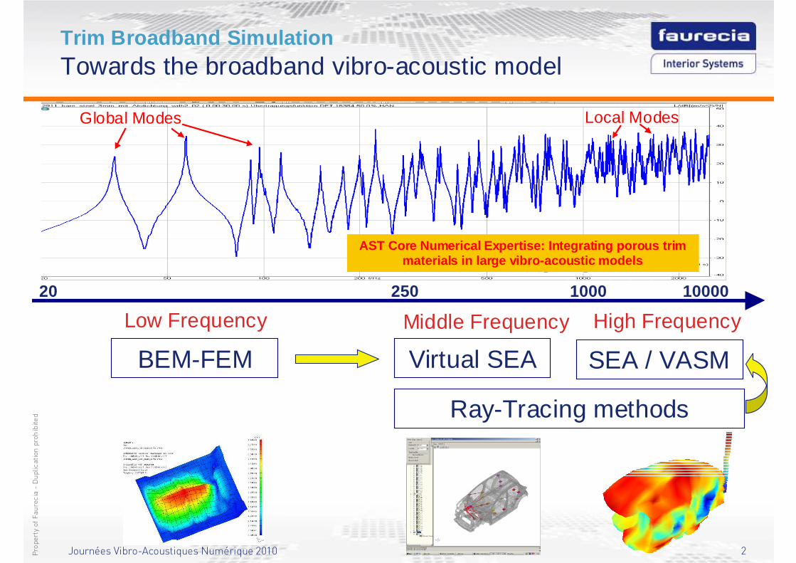
Trim Broadband SimulationTowards the broadband vibro-acoustic model
20 250 1000 10000
Low Frequency
Global Modes Local Modes
Middle Frequency High Frequency
BEM-FEM Virtual SEA SEA / VASM
AST Core Numerical Expertise: Integrating porous trim materials in large vibro-acoustic models
Ray-Tracing methods
Journées Vibro-Acoustiques Numérique 2010 3Propertyof Faurecia-Duplication prohibited
Trim Broadband SimulationIntroduction
� The introduction of curved trims in SEA or Virtual SEA models requires the obtention of two main parameters: � Damping Loss Factors (DLFs), which represent the damping induced
by the trims to the structure (or the absorption in a cavity).� Coupling Loss Factors (CLFs), which represent the modified radiation
efficiency of the structure induced by the trims (Insertion Loss) coupled to a cavity or a semi-infinite fluid (besides the potentially modified trimmed “structureborne” CLFs of the structure)..
� In order to take into account the curvature effects of 3D shaped trims, the novel technique consists in using poroelastic finite elements for getting the:� Curved Insertion Loss of the trims following the automatic sub-
structuring obtained with Virtual SEA.� Damping Loss Factors and Coupling Loss Factors of the trimmed
structure by carrying out an inverse SEA on the structureborne Frequency Response Functions simulated by a trimmed poroelastic FEM model in the middle frequency range.

Journées Vibro-Acoustiques Numérique 2010 4Propertyof Faurecia-Duplication prohibited
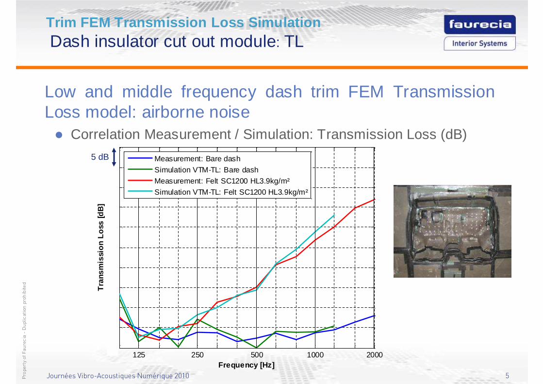
Trim FEM Transmission Loss SimulationDash insulator cut out module: TL
Low and middle frequency dash trim FEM TransmissionLoss model: airborne noise
FEM
BEM emission
Air gap mesh between trim and
baffle
Structure steel (only coupling nodes are represented)
Felt / heavy layer trim
BEM reception
Diffuse field excitation
Air gap between structure and felt
FeltHeavy layer Air gap between
trim and baffle
Trim FEM
(Felt / Heavy layer with air gap)
Journées Vibro-Acoustiques Numérique 2010 5Propertyof Faurecia-Duplication prohibited
Trim FEM Transmission Loss SimulationDash insulator cut out module: TL
Low and middle frequency dash trim FEM Transmission Loss model: airborne noise� Correlation Measurement / Simulation: Transmission Loss (dB)
125 250 500 1000 200020
25
30
35
40
45
50
55
60
65
70
Frequency [Hz]
Tra
nsm
issi
on L
oss
[dB
]
Measurement: Bare dash
Simulation VTM-TL: Bare dash
Measurement: Felt SC1200 HL3.9kg/m²
Simulation VTM-TL: Felt SC1200 HL3.9kg/m²
5 dB
Journées Vibro-Acoustiques Numérique 2010 6Propertyof Faurecia-Duplication prohibited
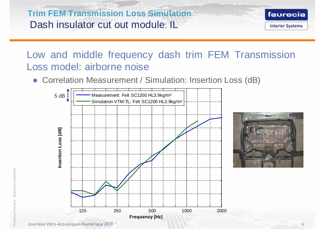
Trim FEM Transmission Loss SimulationDash insulator cut out module: IL
Low and middle frequency dash trim FEM Transmission Loss model: airborne noise� Correlation Measurement / Simulation: Insertion Loss (dB)
125 250 500 1000 2000-5
0
5
10
15
20
25
30
35
40
Frequency [Hz]
Inse
rtion
Los
s [d
B]
Measurement: Felt SC1200 HL3.9kg/m²Simulation VTM-TL: Felt SC1200 HL3.9kg/m²
5 dB
Journées Vibro-Acoustiques Numérique 2010 7Propertyof Faurecia-Duplication prohibited
Trim FEM Transmission Loss SimulationDash insulator cut out module: IL
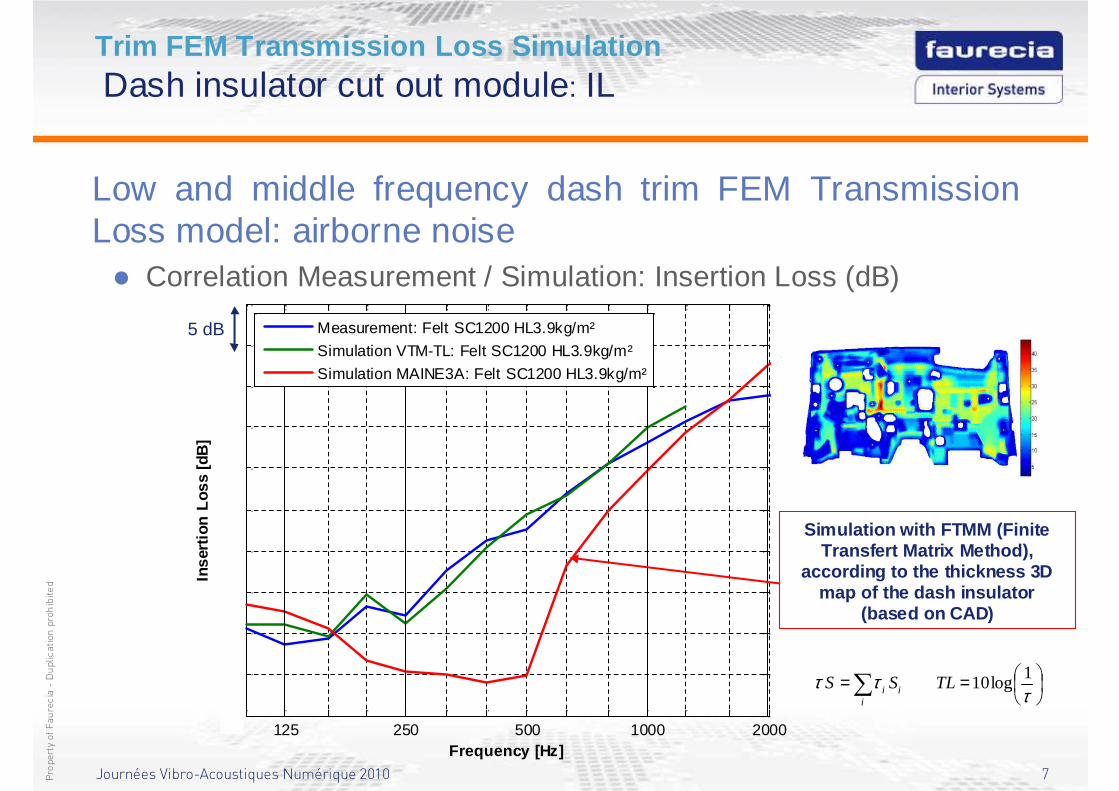
Low and middle frequency dash trim FEM Transmission Loss model: airborne noise� Correlation Measurement / Simulation: Insertion Loss (dB)
Simulation with FTMM (FiniteTransfert Matrix Method),
according to the thickness 3D map of the dash insulator
(based on CAD)
125 250 500 1000 2000-10
-5
0
5
10
15
20
25
30
35
40
Frequency [Hz]
Inse
rtion
Los
s [d
B]
Measurement: Felt SC1200 HL3.9kg/m²
Simulation VTM-TL: Felt SC1200 HL3.9kg/m²
Simulation MAINE3A: Felt SC1200 HL3.9kg/m²
5 dB
==∑ τττ 1
log10TLSSi
ii
Journées Vibro-Acoustiques Numérique 2010 8Propertyof Faurecia-Duplication prohibited
Trim FEM Transmission Loss SimulationDash insulator cut out module: TL
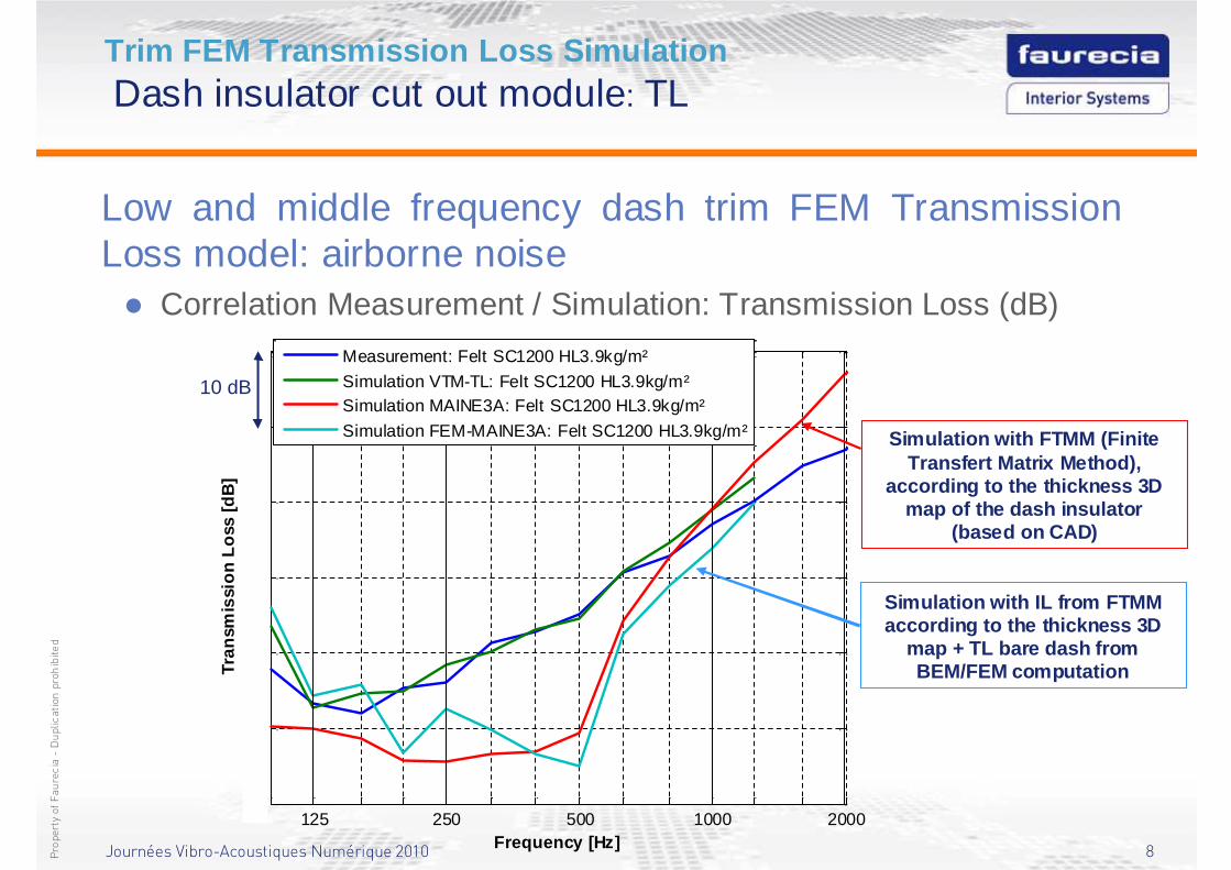
Low and middle frequency dash trim FEM Transmission Loss model: airborne noise� Correlation Measurement / Simulation: Transmission Loss (dB)
Simulation with FTMM (FiniteTransfert Matrix Method),
according to the thickness 3D map of the dash insulator
(based on CAD)
Simulation with IL from FTMM according to the thickness 3D
map + TL bare dash fromBEM/FEM computation
125 250 500 1000 200010
20
30
40
50
60
70
Frequency [Hz]
Tran
smis
sion
Los
s [d
B]
Measurement: Felt SC1200 HL3.9kg/m²
Simulation VTM-TL: Felt SC1200 HL3.9kg/m²Simulation MAINE3A: Felt SC1200 HL3.9kg/m²
Simulation FEM-MAINE3A: Felt SC1200 HL3.9kg/m²
10 dB
Journées Vibro-Acoustiques Numérique 2010 9Propertyof Faurecia-Duplication prohibited
Trim FEM Transmission Loss SimulationDash insulator cut out module: TL
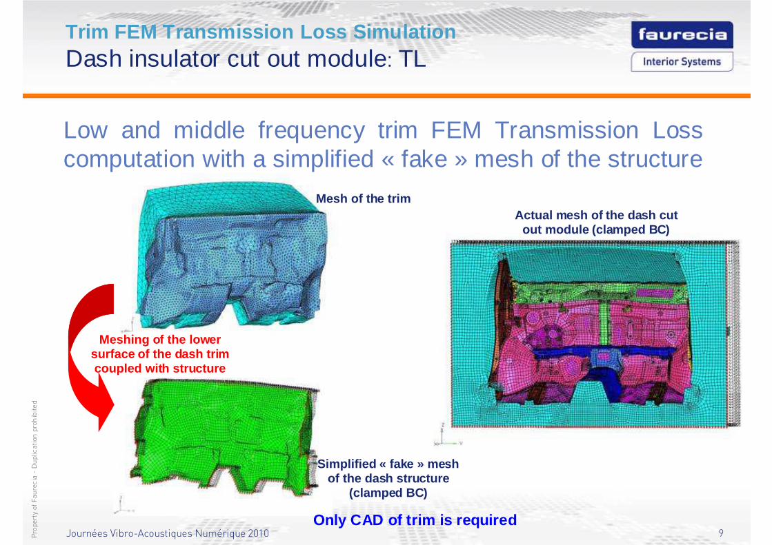
Low and middle frequency trim FEM Transmission Losscomputation with a simplified « fake » mesh of the structure
Mesh of the trim
Simplified « fake » meshof the dash structure
(clamped BC)
Meshing of the lower surface of the dash trimcoupled with structure
Actual mesh of the dash cutout module (clamped BC)
Only CAD of trim is required
Journées Vibro-Acoustiques Numérique 2010 10Propertyof Faurecia-Duplication prohibited
Trim FEM Transmission Loss SimulationDash insulator cut out module: TL
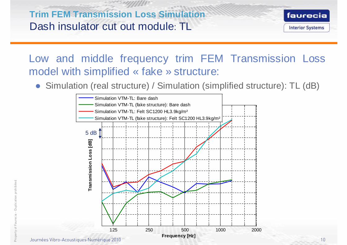
Low and middle frequency trim FEM Transmission Lossmodel with simplified « fake » structure:� Simulation (real structure) / Simulation (simplified structure): TL (dB)
125 250 500 1000 20005
10
15
20
25
30
35
40
45
50
55
60
Frequency [Hz]
Tra
nsm
issi
on
Loss
[dB
]
Simulation VTM-TL: Bare dashSimulation VTM-TL (fake structure): Bare dash
Simulation VTM-TL: Felt SC1200 HL3.9kg/m²
Simulation VTM-TL (fake structure): Felt SC1200 HL3.9kg/m²
5 dB
Journées Vibro-Acoustiques Numérique 2010 11Propertyof Faurecia-Duplication prohibited
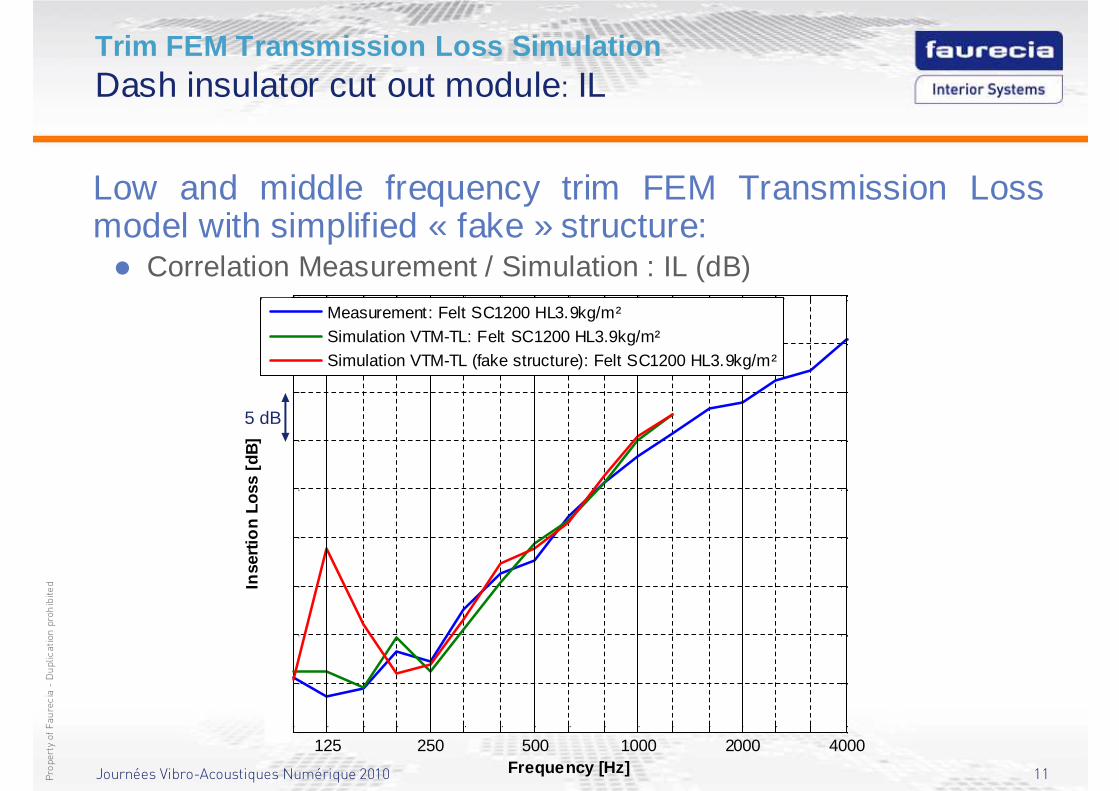
Trim FEM Transmission Loss SimulationDash insulator cut out module: IL
Low and middle frequency trim FEM Transmission Loss model with simplified « fake » structure:� Correlation Measurement / Simulation : IL (dB)
125 250 500 1000 2000 4000-5
0
5
10
15
20
25
30
35
40
Frequency [Hz]
Inse
rtio
n Lo
ss [
dB]
Measurement: Felt SC1200 HL3.9kg/m²Simulation VTM-TL: Felt SC1200 HL3.9kg/m²Simulation VTM-TL (fake structure): Felt SC1200 HL3.9kg/m²
5 dB
Journées Vibro-Acoustiques Numérique 2010 12Propertyof Faurecia-Duplication prohibited
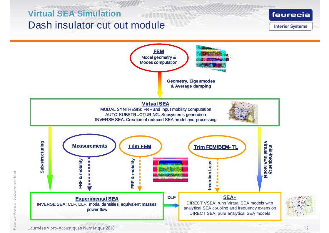
Virtual SEA SimulationDash insulator cut out module
FEMModel geometry &
Modes computation
Virtual SEAMODAL SYNTHESIS: FRF and Input mobility computation
AUTO-SUBSTRUCTURING: Subsystems generationINVERSE SEA: Creation of reduced SEA model and processing
Experimental SEAINVERSE SEA: CLF, DLF, modal densities, equivalent masses,
power flow
SEA+DIRECT VSEA: runs Virtual SEA models with
analytical SEA coupling and frequency extension DIRECT SEA: pure analytical SEA models
Trim FEM
Inse
rtion
Los
s
FR
F &
mob
ility
Sub
-str
uctu
ring m
id-frequencyV
irtual SE
Am
odel
Geometry, Eigenmodes& Average damping
DLF
Measurements Trim FEM/BEM- TL
FRF
& m
obili
ty
FEMModel geometry &
Modes computation
FEMModel geometry &
Modes computation
Virtual SEAMODAL SYNTHESIS: FRF and Input mobility computation
AUTO-SUBSTRUCTURING: Subsystems generationINVERSE SEA: Creation of reduced SEA model and processing
Virtual SEAMODAL SYNTHESIS: FRF and Input mobility computation
AUTO-SUBSTRUCTURING: Subsystems generationINVERSE SEA: Creation of reduced SEA model and processing
Experimental SEAINVERSE SEA: CLF, DLF, modal densities, equivalent masses,
power flow
Experimental SEAINVERSE SEA: CLF, DLF, modal densities, equivalent masses,
power flow
SEA+DIRECT VSEA: runs Virtual SEA models with
analytical SEA coupling and frequency extension DIRECT SEA: pure analytical SEA models
Trim FEMTrim FEM
Inse
rtion
Los
s
FR
F &
mob
ility
Sub
-str
uctu
ring m
id-frequencyV
irtual SE
Am
odel
Geometry, Eigenmodes& Average damping
DLF
Measurements Trim FEM/BEM- TLTrim FEM/BEM- TL
FRF
& m
obili
ty
Journées Vibro-Acoustiques Numérique 2010 13Propertyof Faurecia-Duplication prohibited
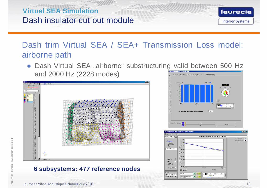
Virtual SEA SimulationDash insulator cut out module
Dash trim Virtual SEA / SEA+ Transmission Loss model: airborne path� Dash Virtual SEA „airborne“ substructuring valid between 500 Hz
and 2000 Hz (2228 modes)
6 subsystems: 477 reference nodes
Journées Vibro-Acoustiques Numérique 2010 14Propertyof Faurecia-Duplication prohibited
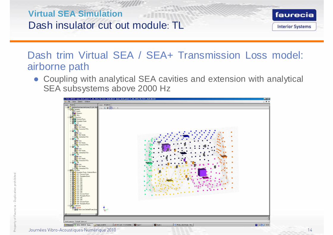
Virtual SEA SimulationDash insulator cut out module: TL
Dash trim Virtual SEA / SEA+ Transmission Loss model: airborne path� Coupling with analytical SEA cavities and extension with analytical
SEA subsystems above 2000 Hz
Journées Vibro-Acoustiques Numérique 2010 15Propertyof Faurecia-Duplication prohibited
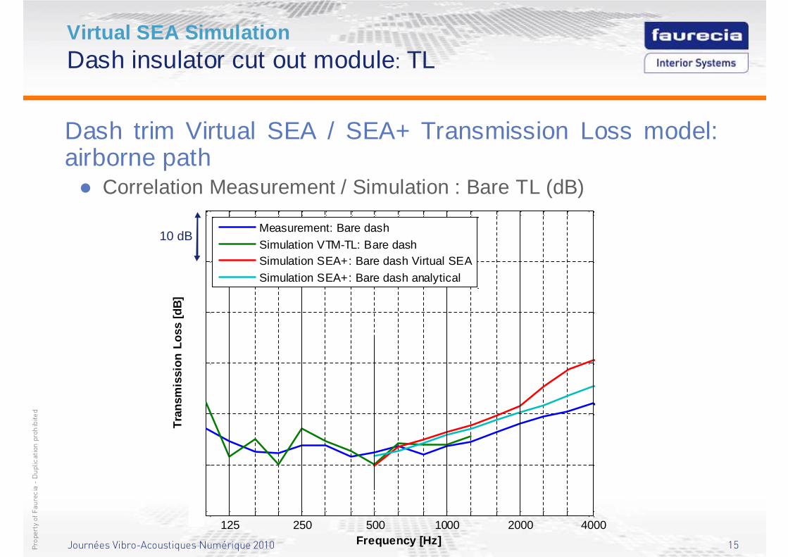
Virtual SEA SimulationDash insulator cut out module: TL
Dash trim Virtual SEA / SEA+ Transmission Loss model: airborne path� Correlation Measurement / Simulation : Bare TL (dB)
125 250 500 1000 2000 400010
20
30
40
50
60
70
Frequency [Hz]
Tra
nsm
issi
on L
oss
[dB
]
Measurement: Bare dash
Simulation VTM-TL: Bare dashSimulation SEA+: Bare dash Virtual SEA
Simulation SEA+: Bare dash analytical
10 dB
Journées Vibro-Acoustiques Numérique 2010 16Propertyof Faurecia-Duplication prohibited
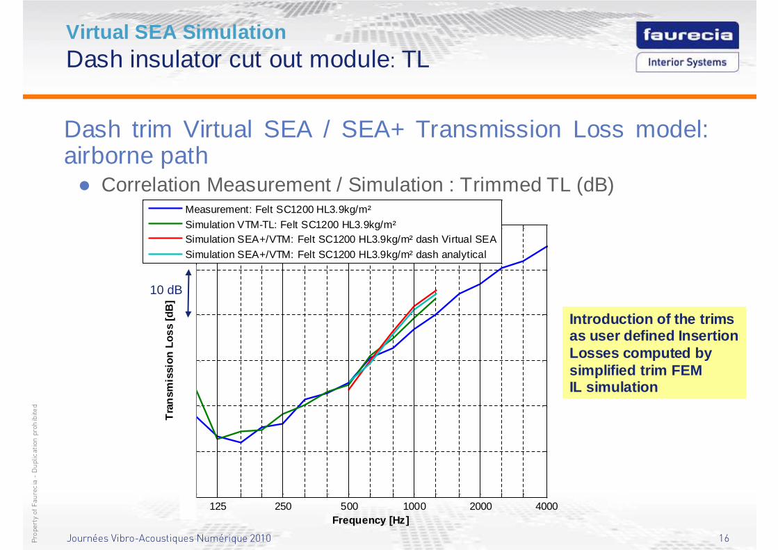
Virtual SEA SimulationDash insulator cut out module: TL
Dash trim Virtual SEA / SEA+ Transmission Loss model: airborne path� Correlation Measurement / Simulation : Trimmed TL (dB)
125 250 500 1000 2000 400010
20
30
40
50
60
70
Frequency [Hz]
Tra
nsm
issi
on L
oss
[dB
]
Measurement: Felt SC1200 HL3.9kg/m²
Simulation VTM-TL: Felt SC1200 HL3.9kg/m²Simulation SEA+/VTM: Felt SC1200 HL3.9kg/m² dash Virtual SEA
Simulation SEA+/VTM: Felt SC1200 HL3.9kg/m² dash analytical
10 dB
Introduction of the trims as user defined Insertion Losses computed by simplified trim FEM IL simulation
Journées Vibro-Acoustiques Numérique 2010 17Propertyof Faurecia-Duplication prohibited
125 250 500 1000 2000 400010
20
30
40
50
60
70
80
Frequency [Hz]
Tra
nsm
issi
on L
oss
[dB
]
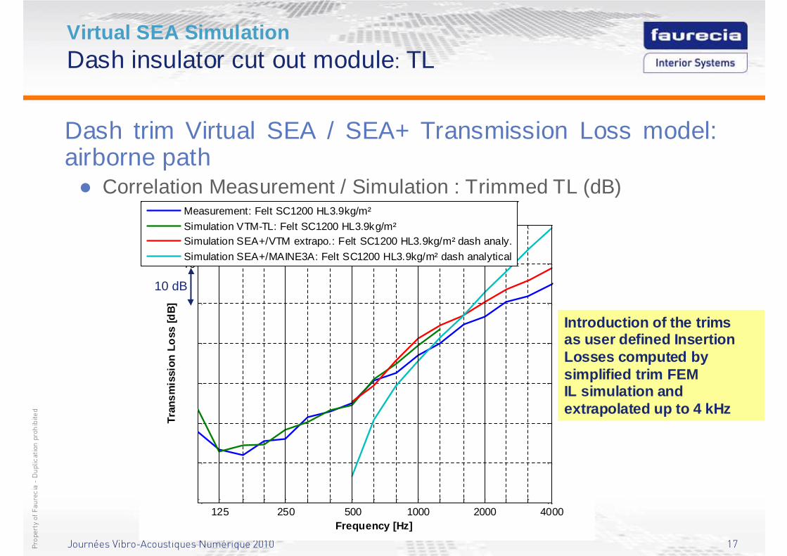
Measurement: Felt SC1200 HL3.9kg/m²
Simulation VTM-TL: Felt SC1200 HL3.9kg/m²Simulation SEA+/VTM extrapo.: Felt SC1200 HL3.9kg/m² dash analy.
Simulation SEA+/MAINE3A: Felt SC1200 HL3.9kg/m² dash analytical
10 dB
Virtual SEA SimulationDash insulator cut out module: TL
Dash trim Virtual SEA / SEA+ Transmission Loss model: airborne path� Correlation Measurement / Simulation : Trimmed TL (dB)
Introduction of the trims as user defined Insertion Losses computed by simplified trim FEM IL simulation and extrapolated up to 4 kHz
Journées Vibro-Acoustiques Numérique 2010 18Propertyof Faurecia-Duplication prohibited
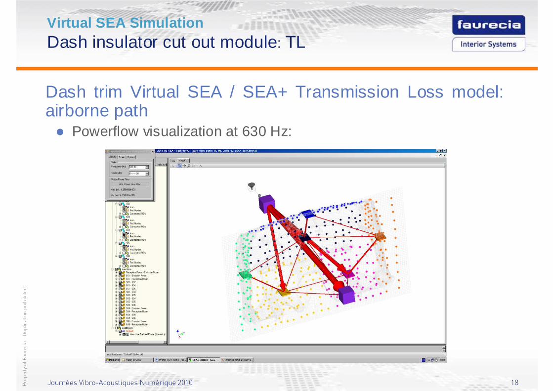
Virtual SEA SimulationDash insulator cut out module: TL
Dash trim Virtual SEA / SEA+ Transmission Loss model: airborne path� Powerflow visualization at 630 Hz:
Journées Vibro-Acoustiques Numérique 2010 19Propertyof Faurecia-Duplication prohibited
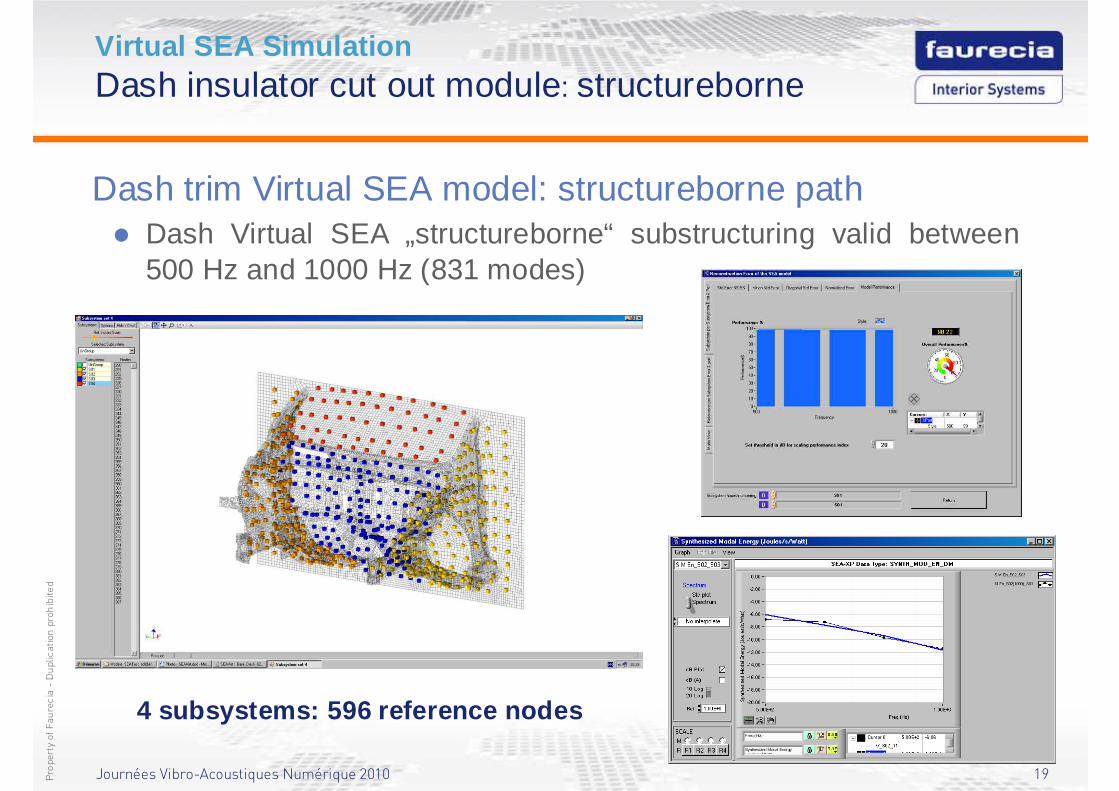
Virtual SEA SimulationDash insulator cut out module: structureborne
Dash trim Virtual SEA model: structureborne path� Dash Virtual SEA „structureborne“ substructuring valid between
500 Hz and 1000 Hz (831 modes)
4 subsystems: 596 reference nodes
Journées Vibro-Acoustiques Numérique 2010 20Propertyof Faurecia-Duplication prohibited
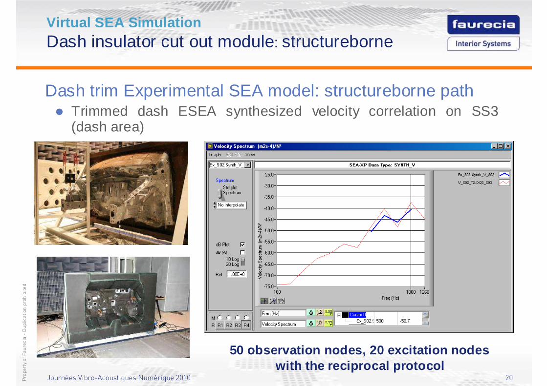
Virtual SEA SimulationDash insulator cut out module: structureborne
Dash trim Experimental SEA model: structureborne path� Trimmed dash ESEA synthesized velocity correlation on SS3
(dash area)
50 observation nodes, 20 excitation nodeswith the reciprocal protocol
Journées Vibro-Acoustiques Numérique 2010 21Propertyof Faurecia-Duplication prohibited
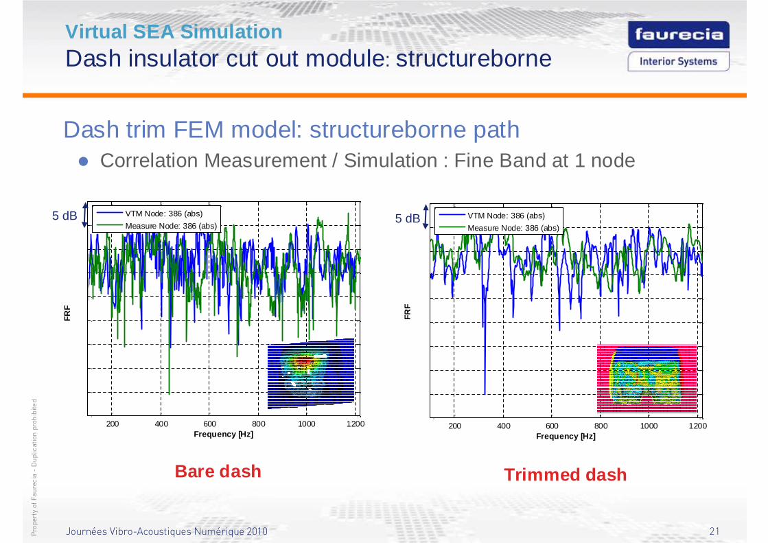
Virtual SEA SimulationDash insulator cut out module: structureborne
Dash trim FEM model: structureborne path� Correlation Measurement / Simulation : Fine Band at 1 node
Bare dash Trimmed dash
200 400 600 800 1000 1200-45
-40
-35
-30
-25
-20
-15
-10
-5
0
Frequency [Hz]
FRF
VTM Node: 386 (abs)
Measure Node: 386 (abs)5 dB
200 400 600 800 1000 1200-40
-35
-30
-25
-20
-15
-10
-5
0
5
Frequency [Hz]
frf
VTM Node: 386 (abs)
Measure Node: 386 (abs)
FRF
5 dB
Journées Vibro-Acoustiques Numérique 2010 22Propertyof Faurecia-Duplication prohibited
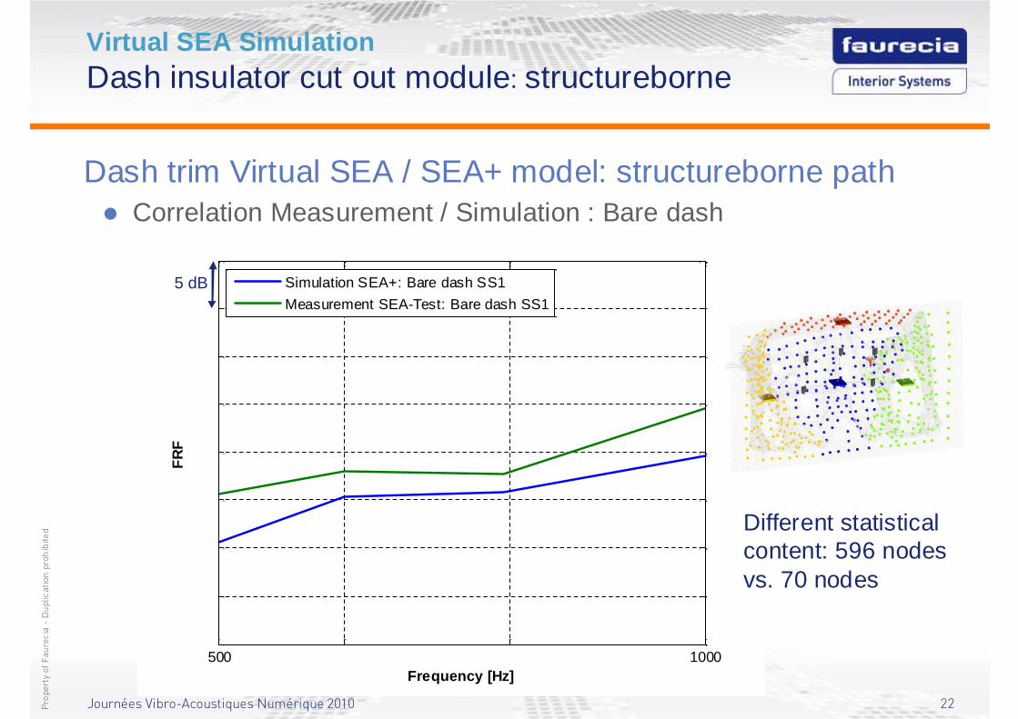
Virtual SEA SimulationDash insulator cut out module: structureborne
Dash trim Virtual SEA / SEA+ model: structureborne path� Correlation Measurement / Simulation : Bare dash
500 1000-65
-60
-55
-50
-45
-40
-35
-30
-25
Frequency [Hz]
FR
F
Simulation SEA+: Bare dash SS1
Measurement SEA-Test: Bare dash SS15 dB
Different statistical content: 596 nodes vs. 70 nodes
Journées Vibro-Acoustiques Numérique 2010 23Propertyof Faurecia-Duplication prohibited
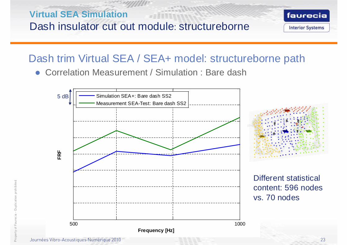
Virtual SEA SimulationDash insulator cut out module: structureborne
Dash trim Virtual SEA / SEA+ model: structureborne path� Correlation Measurement / Simulation : Bare dash
500 1000-65
-60
-55
-50
-45
-40
-35
-30
-25
Frequency [Hz]
FR
F
Simulation SEA+: Bare dash SS2
Measurement SEA-Test: Bare dash SS25 dB
Different statistical content: 596 nodes vs. 70 nodes
Journées Vibro-Acoustiques Numérique 2010 24Propertyof Faurecia-Duplication prohibited
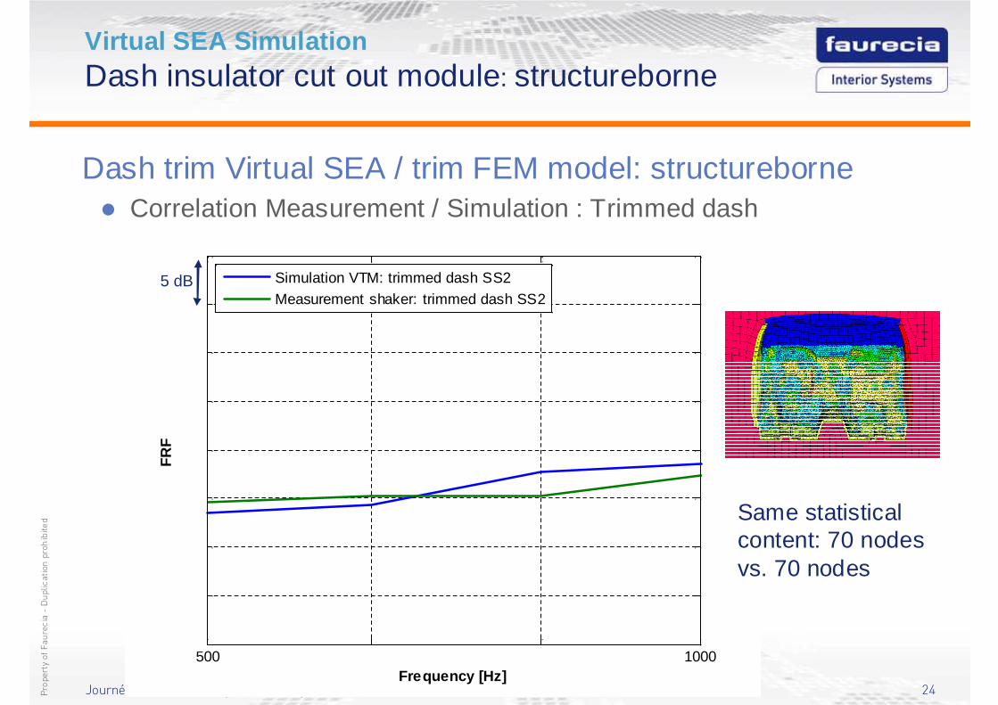
Virtual SEA SimulationDash insulator cut out module: structureborne
Dash trim Virtual SEA / trim FEM model: structureborne� Correlation Measurement / Simulation : Trimmed dash
500 1000-20
-15
-10
-5
0
5
10
15
20
Frequency [Hz]
FR
F
Simulation VTM: trimmed dash SS2
Measurement shaker: trimmed dash SS25 dB
Same statistical content: 70 nodes vs. 70 nodes
Journées Vibro-Acoustiques Numérique 2010 25Propertyof Faurecia-Duplication prohibited
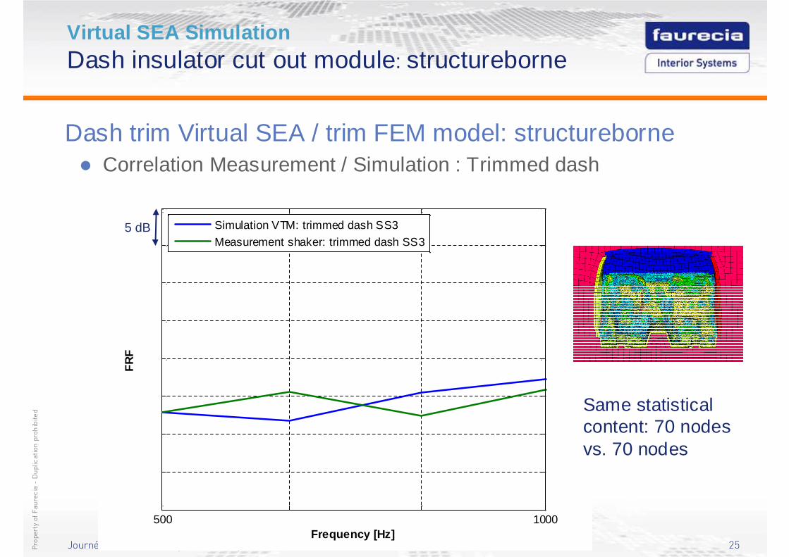
Virtual SEA SimulationDash insulator cut out module: structureborne
Dash trim Virtual SEA / trim FEM model: structureborne� Correlation Measurement / Simulation : Trimmed dash
500 1000-20
-15
-10
-5
0
5
10
15
20
Frequency [Hz]
FR
F
Simulation VTM: trimmed dash SS3
Measurement shaker: trimmed dash SS35 dB
Same statistical content: 70 nodes vs. 70 nodes
Journées Vibro-Acoustiques Numérique 2010 26Propertyof Faurecia-Duplication prohibited
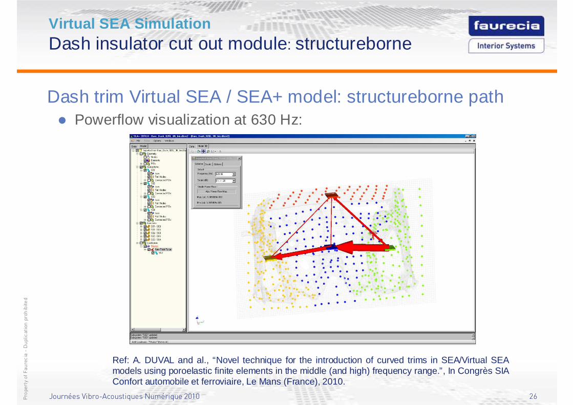
Virtual SEA SimulationDash insulator cut out module: structureborne
Dash trim Virtual SEA / SEA+ model: structureborne path� Powerflow visualization at 630 Hz:
Ref: A. DUVAL and al., “Novel technique for the introduction of curved trims in SEA/Virtual SEA models using poroelastic finite elements in the middle (and high) frequency range.”, In Congrès SIA Confort automobile et ferroviaire, Le Mans (France), 2010.
Journées Vibro-Acoustiques Numérique 2010 27Propertyof Faurecia-Duplication prohibited
Ray-Tracing SimulationVehicle Acoustic Synthesis Method
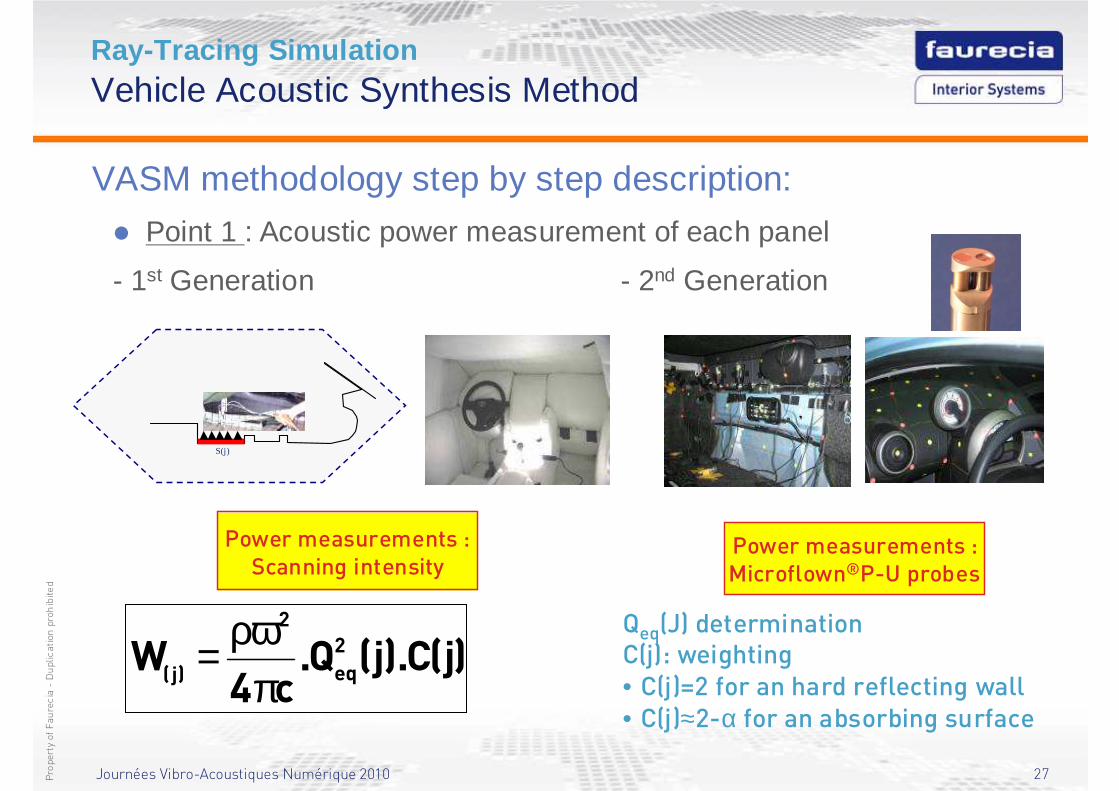
VASM methodology step by step description:
� Point 1 : Acoustic power measurement of each panel
- 1st Generation - 2nd Generation
Power measurements :Scanning intensity
)j(C).j(Q.c4
W 2
eq
2
)j( πρω= )j(C).j(Q.
c4W 2
eq
2
)j( πρω=
Qeq(J) determinationC(j): weighting• C(j)=2 for an hard reflecting wall• C(j)≈2-α for an absorbing surface
S(j)
Power measurements :Microflown®P-U probes
Journées Vibro-Acoustiques Numérique 2010 28Propertyof Faurecia-Duplication prohibited
Ray-Tracing SimulationSource localization analysis
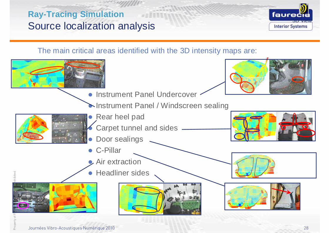
The main critical areas identified with the 3D intensity maps are:
� Instrument Panel Undercover
� Instrument Panel / Windscreen sealing
� Rear heel pad
� Carpet tunnel and sides
� Door sealings
� C-Pillar
� Air extraction
� Headliner sides
3D View
Journées Vibro-Acoustiques Numérique 2010 29Propertyof Faurecia-Duplication prohibited
Ray-Tracing SimulationVehicle Acoustic Synthesis Method
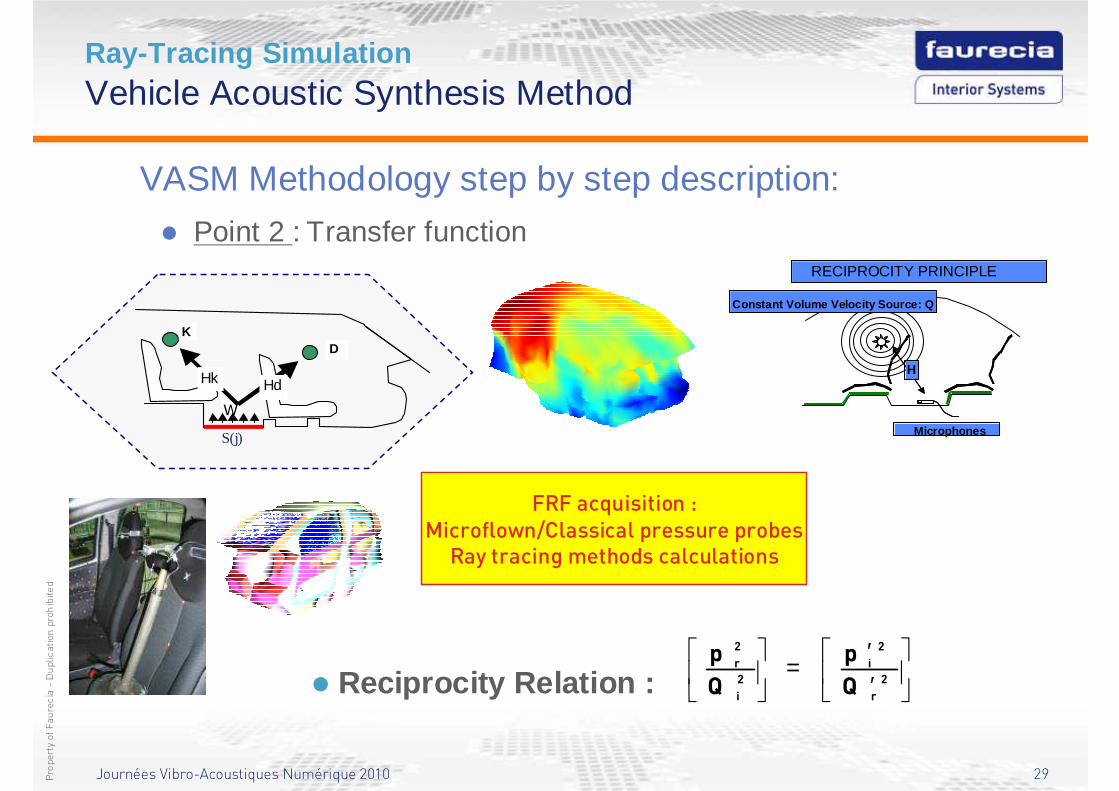
VASM Methodology step by step description:
� Point 2 : Transfer function
� Reciprocity Relation :
′′
=
2
r
2
i
2
i
2
r
Q
p
Q
p
FRF acquisition :Microflown/Classical pressure probes
Ray tracing methods calculations
Constant Volume Velocity Source: Q
Microphones
RECIPROCITY PRINCIPLE
H
Constant Volume Velocity Source: Q
Microphones
RECIPROCITY PRINCIPLE
H
W
DK
HdHk
S(j)
Journées Vibro-Acoustiques Numérique 2010 30Propertyof Faurecia-Duplication prohibited
Ray-Tracing SimulationVehicle Acoustic Synthesis Method
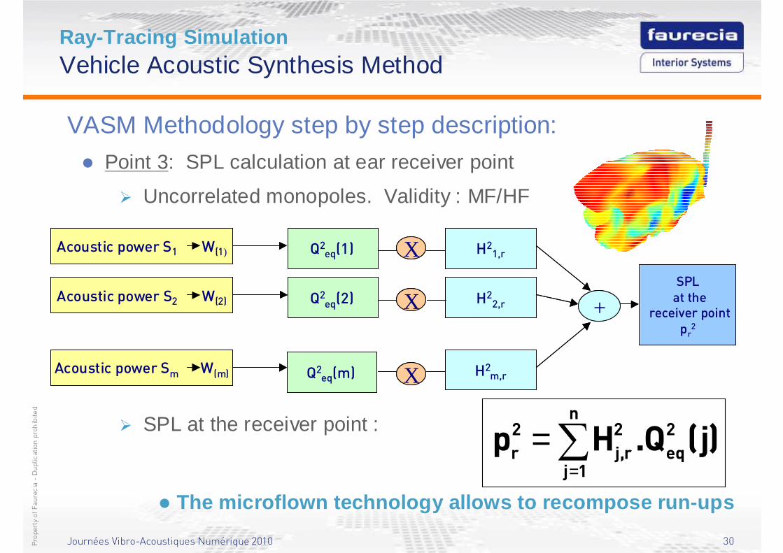
VASM Methodology step by step description:
� Point 3: SPL calculation at ear receiver point
� Uncorrelated monopoles. Validity : MF/HF
� SPL at the receiver point :)j(Q.Hp
n
1j
2
eq
2
r,j
2
r ∑=
=
1
SPLat the
receiver pointpr
2
Acoustic power Sm W(m)
Acoustic power S2 W(2)
Acoustic power S1 W(1) Q2eq(1)
Q2eq(2)
Q2eq(m)
H21,r
H2m,r
H22,r
X
X
X
+
1
SPLat the
receiver pointpr
2
Acoustic power Sm W(m)Acoustic power Sm W(m)
Acoustic power S2 W(2)Acoustic power S2 W(2)
Acoustic power S1 W(1)Acoustic power S1 W(1) Q2eq(1)
Q2eq(2)
Q2eq(m)
H21,r
H2m,r
H22,r
X
X
X
+
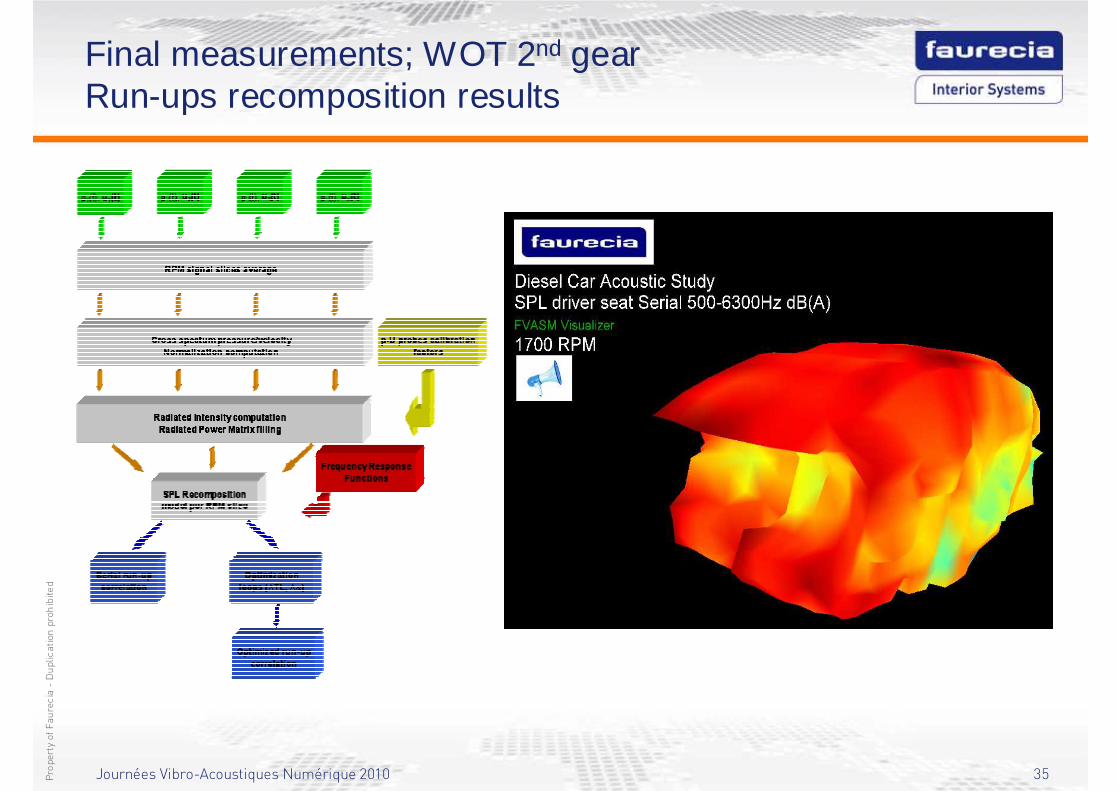
� The microflown technology allows to recompose run-ups
Journées Vibro-Acoustiques Numérique 2010 31Propertyof Faurecia-Duplication prohibited
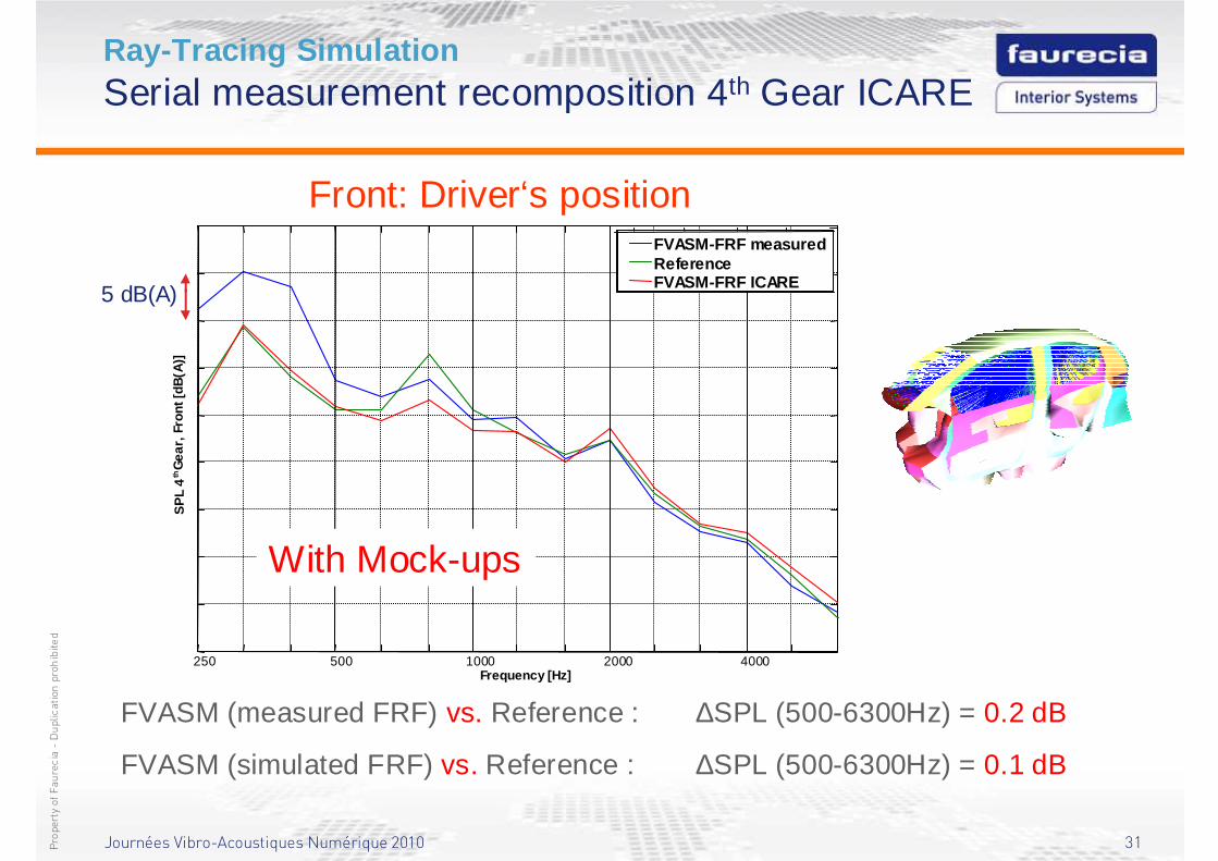
Ray-Tracing SimulationSerial measurement recomposition 4th Gear ICARE
FVASM (measured FRF) vs. Reference : ∆SPL (500-6300Hz) = 0.2 dB
FVASM (simulated FRF) vs. Reference : ∆SPL (500-6300Hz) = 0.1 dB
Front: Driver‘s position
Frequency [Hz]
5 dB(A)
250 500 1000 2000 4000
SP
L 4
thG
ear,
Fro
nt [d
B(A
)]
FVASM-FRF measuredReferenceFVASM-FRF ICARE
With Mock-ups
Journées Vibro-Acoustiques Numérique 2010 32Propertyof Faurecia-Duplication prohibited
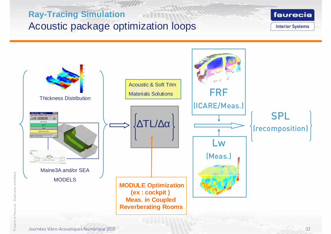
Ray-Tracing SimulationAcoustic package optimization loops
SPL(recomposition)
FRF(ICARE/Meas.)
Lw(Meas.)
Maine3A and/or SEA
MODELS
Thickness Distribution
∆TL/∆α
MODULE Optimization(ex : cockpit )
Meas. in Coupled Reverberating Rooms
Acoustic & Soft Trim
Materials Solutions
Journées Vibro-Acoustiques Numérique 2010 33Propertyof Faurecia-Duplication prohibited
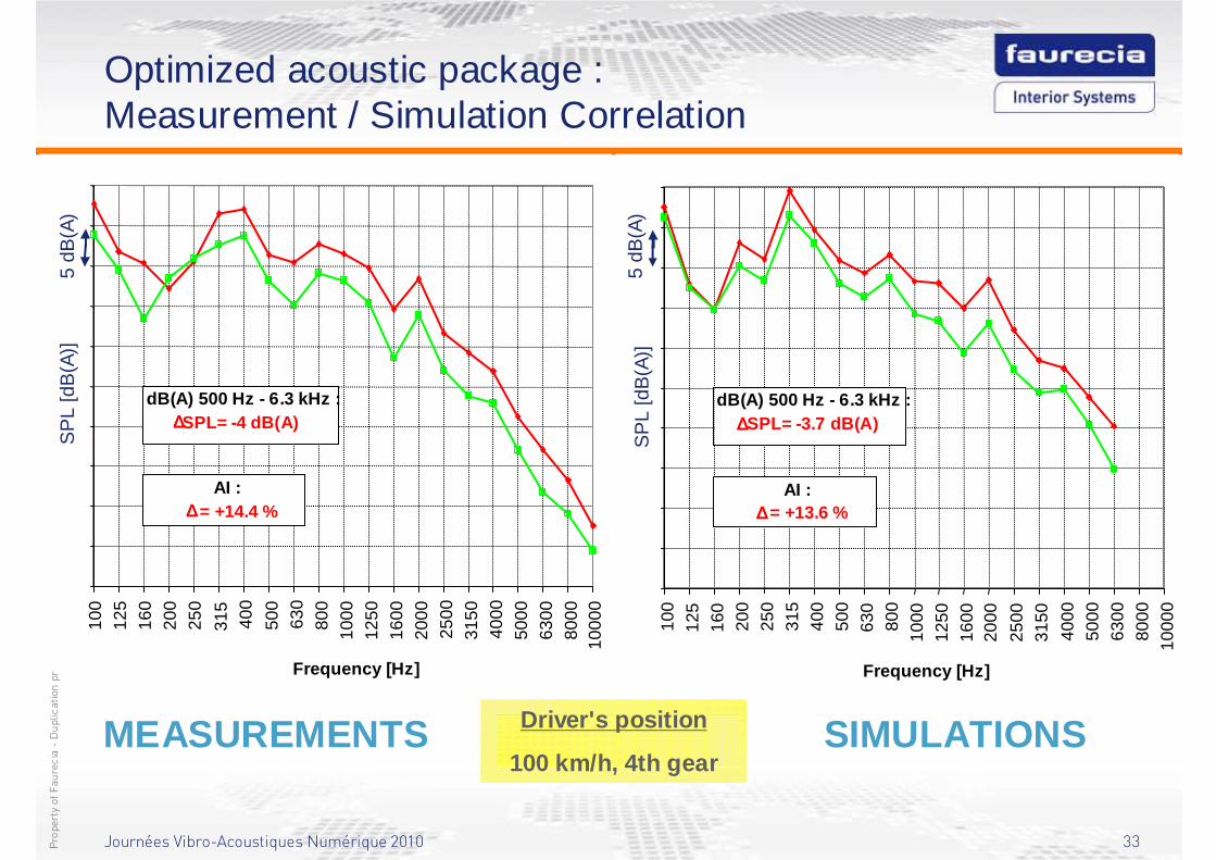
Optimized acoustic package :Measurement / Simulation Correlation
Driver's position
100 km/h, 4th gearMEASUREMENTS SIMULATIONS
SP
L [d
B(A
)]5
dB(A
)10
012
516
020
025
0
315
400
500
630
800
1000
1250
1600
2000
2500
3150
4000
5000
6300
8000
1000
0
Frequency [Hz]
dB(A) 500 Hz - 6.3 kHz :∆∆∆∆SPL= -4 dB(A)
AI :∆∆∆∆ = +14.4 %
SP
L [d
B(A
)]5
dB(A
)
100
125
160
200
250
315
400
500
630
800
1000
1250
1600
2000
2500
3150
4000
5000
6300
8000
1000
0
Frequency [Hz]
dB(A) 500 Hz - 6.3 kHz :∆∆∆∆SPL= -3.7 dB(A)
AI :∆∆∆∆ = +13.6 %
Journées Vibro-Acoustiques Numérique 2010 34Propertyof Faurecia-Duplication prohibited
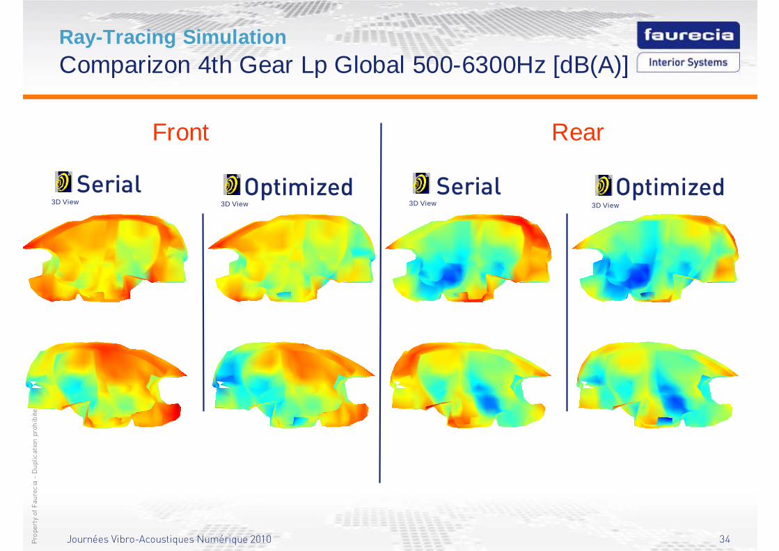
Ray-Tracing SimulationComparizon 4th Gear Lp Global 500-6300Hz [dB(A)]
Serial Optimized
Front Rear
Serial Optimized3D View3D View3D View3D View
Journées Vibro-Acoustiques Numérique 2010 35Propertyof Faurecia-Duplication prohibited
Final measurements; WOT 2nd gearRun-ups recomposition results
Journées Vibro-Acoustiques Numérique 2010 36Propertyof Faurecia-Duplication prohibited
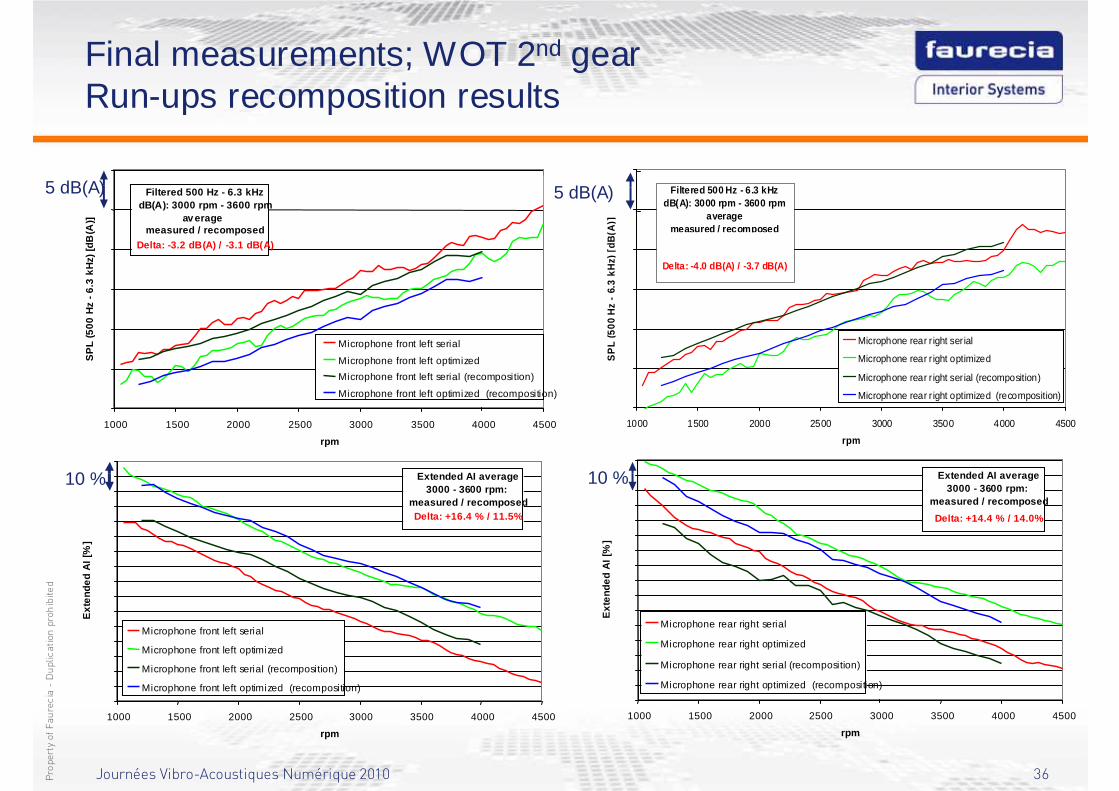
Final measurements; WOT 2nd gearRun-ups recomposition results
5 dB(A)
1000 1500 2000 2500 3000 3500 4000 4500
rpm
SP
L (5
00
Hz
-6
.3 k
Hz)
[dB
(A)]
Microphone front left serial
Microphone front left optimized
Microphone front left serial (recomposition)
Microphone front left optimized (recomposition)
Filtered 500 Hz - 6.3 kHzdB(A): 3000 rpm - 3600 rpm
av eragemeasured / recomposed
Delta: -3.2 dB(A) / -3.1 dB(A)
10 %
1000 1500 2000 2500 3000 3500 4000 4500
rpm
Ext
end
ed
AI
[%]
Microphone front left serial
Microphone front left optimized
Microphone front left serial (recomposition)
Microphone front left optimized (recomposition)
Extended AI average3000 - 3600 rpm:
measured / recomposedDelta: +16.4 % / 11.5%
10 %
1000 1500 2000 2500 3000 3500 4000 4500
rpm
Ext
end
ed
AI
[%]
Microphone rear right serial
Microphone rear right optimized
Microphone rear right serial (recomposition)
Microphone rear right optimized (recomposition)
Extended AI average3000 - 3600 rpm:
measured / recomposed
Delta: +14.4 % / 14.0%
45
50
55
60
65
70
75
1000 1500 2000 2500 3000 3500 4000 4500
rpm
SP
L (5
00 H
z -
6.3
kHz)
[dB
(A)]
Microphone rear r ight serial
Microphone rear r ight optimized
Microphone rear r ight serial (recomposition)
Microphone rear r ight optimized (recomposition)
Filtered 500 Hz - 6.3 kHzdB(A): 3000 rpm - 3600 rpm
averagemeasured / recomposed
Serial : 62.9 dB(A) / 62.7 dB(A)Optim : 58.9 dB(A) / 59.0 dB(A)Delta: -4.0 dB(A) / -3.7 dB(A)
5 dB(A)
Journées Vibro-Acoustiques Numérique 2010 37Propertyof Faurecia-Duplication prohibited
Trim Broadband SimulationConclusion
Towards the broadband vibro-acoustic model with trims:� This vibro-acoustic simulation study illustrates once again the
efficiency of combining FEM with inverse SEA approaches in the
middle frequency range, which is already known as Virtual SEA,
but also the pertinence of using trim FEM simulation, namely
poroelastic finite elements, within this modeling framework for an
accurate introduction of curved or 3D shaped trims under both
structureborne and airborne excitations.
� The results of the airborne Transmission Loss simulations
combining trim FEM with Virtual SEA simulations in the middle
frequency range up to 1250 Hz and SEA in the high frequency
range up to 4000 Hz here, by extrapolating the Insertion Loss
slopes, are very good and extremely promising.
Journées Vibro-Acoustiques Numérique 2010 38Propertyof Faurecia-Duplication prohibited
Trim Broadband SimulationConclusion
Towards the broadband vibro-acoustic model with trims:� Indeed, considering the high curvature of this dash cut out module
compared to previous Transmission Loss investigations on floor
modules, this work seems to solve definitely the curvature issue of
trims with poroelastic finite element simulation.
� The structureborne vibro-acoustic responses computed with this
combined technique in the middle frequency range are giving good
results also and are therefore promising as well, even if some
further work is still to be done: trim FEM simulation will have to be
more integrated in the Virtual SEA process in the future…
Journées Vibro-Acoustiques Numérique 2010 39Propertyof Faurecia-Duplication prohibited
Trim Broadband SimulationConclusion
Towards the broadband vibro-acoustic model with trims:� The Vehicle Acoustic Synthesis Method shows the pertinence of
combining SEA (computed Radiated Powers in a cavity) with Ray-
Tracing simulations (computed Frequency Response Functions) in
order to improve the spatial information content of SEA in the
middle and high frequency.
� The combination of BEM-FEM, Virtual SEA / SEA and Ray-Tracing
simulation methods brings the hope to access in the near future to
a fully numerical broadband vibro-acoustic model…

Journées Vibro-Acoustiques Numérique 2010 40Propertyof Faurecia-Duplication prohibited
Thank you for your attention…
Recommended