Numerical simulation of low-®eld thermally stimulatedconductivity in a-Si:H
T. Sma�õl a, M. Aoucher a, T. Mohammed-Brahim b,*
a Laboratoire des Couches Minces et des Semiconducteurs, Institut de Physique, USTHB, BP 32 El Alia, 16111 Bab-Ezzouar, Alger,
Algeriab GMV, UPRESA-CNRS 6076, Universit�e de Rennes I, Campus de Beaulieu, Batiment 11B, 35042 Rennes cedex, France
Abstract
A numerical simulation of the thermally stimulated conductivity (TSC) in hydrogenated amorphous silicon (a-Si:H)
is presented as a function of temperature. All the possible thermal emission, trapping and recombination transitions of
free carriers between gap and extended states are considered. The standard distribution of localized states in a-Si:H is
used. The rate equations of free and trapped carriers are set up following the Shockley±Read±Hall statistics for both
electrons and holes. By solving the complete set of non-linear di�erential equations the TSC response is calculated
without further assumption. The calculation is valid for the smaller electric ®eld approximation and for temperatures
high enough to neglect the hopping conduction. For a typical set of microscopic parameters, the calculated TSC curve
has two prevalent peaks. The general shape of the TSC and the origin of each peak is given by using the quasi-Fermi
level concept and the respective localized charge densities variations. Ó 2000 Elsevier Science B.V. All rights reserved.
1. Introduction
The thermally stimulated current technique is auseful method for studying the amorphous semi-conductor defect states density. It consists of ®rst®lling the trap states by excitation at a low tem-perature. After a delay period, the sample is heatedin the dark while the thermostimulated current ismeasured. The di�erence of the measured con-ductivity and the equilibrium dark conductivity,measured in the same conditions, is the thermallystimulated conductivity (TSC) spectrum. The TSC
method has been used to determine the deep levelsin crystalline semiconductors for which the theoryis well understood [1]. In a-Si:H, it is di�cult tointerpret experimental results of TSC because ofthe complex distribution of the localized states.The experimental TSC curves typically have twopeaks. The shape of the curve and the peak tem-peratures depend on the a-Si:H sample species andthe experimental conditions. An early theory wasdeveloped by Simmons et al. [2] for the TSC insemiconductors having arbitrary trap distribu-tions. This theoretical approach is applied directly[3] or by using an adapted TSC technique onSchottky structures [4]. Another theory of TSC hasbeen developed by assuming that retrapping isnegligible and that there is quasi-equilibrium be-tween thermal emission and recombination.Photoconductivity and TSC measurements are
Journal of Non-Crystalline Solids 266±269 (2000) 376±379
www.elsevier.com/locate/jnoncrysol
* Corresponding author. Tel.: +33-2 99 28 16 74; fax: +33-2 99
28 16 74.
E-mail address: [email protected] (T. Mohammed-
Brahim).
0022-3093/00/$ - see front matter Ó 2000 Elsevier Science B.V. All rights reserved.
PII: S 0 0 2 2 - 3 0 9 3 ( 9 9 ) 0 0 7 3 4 - 6
combined to determine partially the density ofstates (DOS) in a-Si:H. A background of the re-lated works is given in Ref. [5]. However, limita-tions of such a TSC technique for studying theDOS of a-Si:H are reported [6]. More recently aninterpretation of the TSC at low temperatures isreported [7] based on the hopping motion of car-riers.
The aim of this report is to present a moregeneralized numerical simulation of TSC in a-Si:H. Especially, we present here the quasi-Fermilevel (QFL) approach to explain the general shapeof the spectrum.
2. Simulation details
The standard DOS model of a-Si:H as describedin Ref. [8] is used. It consists of two exponentialdistributions of conduction-band tail (CBT) andvalence-band tail (VBT) states and a single set ofdangling-bond (DB) correlated discrete levels witha positive correlation energy, U. The DBs havethree charge states: D�, D0 and Dÿ. All possiblethermal emission, trapping and recombinationprocesses of free carriers, occurring between ex-tended and localized states, are taken into account.Transitions of both electrons and holes are con-sidered according to the Hall±Shockley±Readstatistics. Transitions between localized states areneglected.
The TSC is calculated from
rTSC�t� � �eln n�t� � elp p�t�� ÿ rd�t�; �1�
where e is the electronic charge, ln and lp are theband mobilities, t is the time variable and, n�t� andp�t� are the free electron and free hole densities.rd�t� is the dark conductivity and is simply calcu-lated from the charge neutrality condition equa-tion [8]. During the TSC process, the temperatureis raised at a constant rate, b, following T �t� � bt� T0, where T0 is the temperature where the heatingstarts.
Under such non-equilibrium conditions, n�t�and p�t� can be calculated from the numericalresolution of the coupled rate equations
dn�t�dt�X
i
ectn Ei; t� �Qct Ei; t� �
ÿ n�t�X
i
Cctn Nct Ei� �� ÿ Qct Ei; t� ��
�X
i
evtn Ei; t� � Nvt Ei� �� ÿ Qvt Ei; t� ��
ÿ n�t�X
i
Cvtn Qvt Ei; t� � � eÿn �t�Qÿdb�t�
� e0n�t�Q0
db�t� ÿ n�t�C0nQ0
db�t�ÿ n�t�C�n Q�db�t�; �2�
dp�t�dt�X
i
ectp Ei; t� � Nct Ei� �� ÿ Qct Ei; t� ��
ÿ p�t�X
i
Cctp Qct Ei; t� �
�X
i
evtp Ei; t� �Qvt Ei; t� �
ÿ p�t�X
i
Cvtp Nvt Ei� �� ÿ Qvt Ei; t� ��
� e�p �t�Q�db�t� � e0p�t�Q0
db�t�ÿ p�t�Cÿp Qÿdb�t� ÿ p�t�C0
pQ0db�t�: �3�
For the purpose of the computation, the con-tinuous distributions of CBT and VBT states arereplaced with two series of discrete levels Nct�Ei�and Nvt�Ei�. Qct�Ei; t� is the density of electronstrapped on i level of the CBT and Qvt�Ei; t� thedensity of holes trapped on i level of the VBT, Cct
n
and Cctp (Cvt
n and Cvtp ) are the capture coe�cients of
electrons and holes at the centers of the CBT(VBT) which are taken independent of energy.ect
n �Ei; t�, ectp �Ei; t�, evt
n �Ei; t� and evtp �Ei; t� are the
respective rate of emission of carriers from a levelat energy Ei of the band-tails. Q�db�t�, Q0
db�t� andQÿdb�t� are the D�, D0 and Dÿ densities respec-tively. C�n , C0
n, C0p and Cÿp are the capture coe�-
cients of electrons and holes by the DBs. eÿn �t�,e0
n�t�, e0p�t� and e�p �t� are the respective electron and
hole thermal emission coe�cients from DBs.The trapped charge density at each discretized
level of both band-tails and the di�erent chargedDB densities are time dependent. Therefore, it isnecessary to add their respective rate equationsto Eqs. (2) and (3). We obtain a set of coupled
T. Sma�õl et al. / Journal of Non-Crystalline Solids 266±269 (2000) 376±379 377
non-linear equations. An implicit numericalmethod is used for solving the resulting sti� systemto calculate the TSC curve versus temperature.Initial steady state densities at starting tempera-ture, T0, are numerically calculated from thecharge neutrality and the net recombinationequations [8]. During the waiting time the photo-conductivity decay is calculated by the same dif-ferential equations as TSC.
3. Results of the simulation and discussion
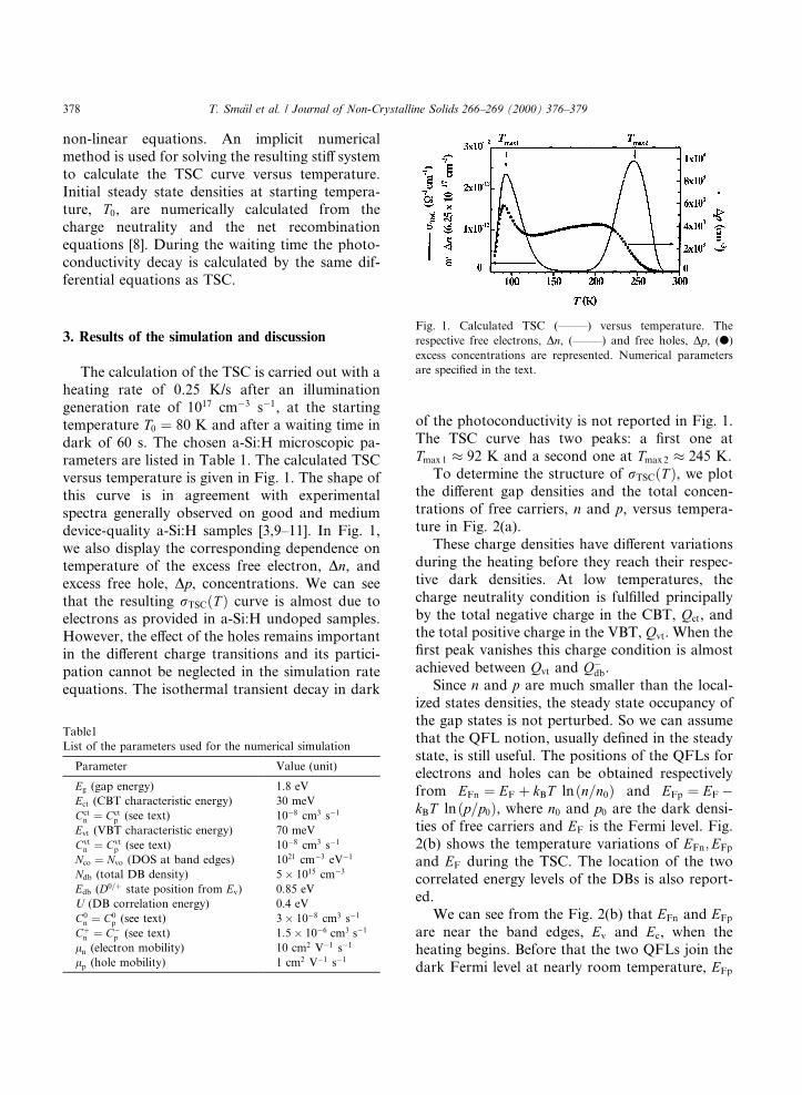
The calculation of the TSC is carried out with aheating rate of 0.25 K/s after an illuminationgeneration rate of 1017 cmÿ3 sÿ1, at the startingtemperature T0 � 80 K and after a waiting time indark of 60 s. The chosen a-Si:H microscopic pa-rameters are listed in Table 1. The calculated TSCversus temperature is given in Fig. 1. The shape ofthis curve is in agreement with experimentalspectra generally observed on good and mediumdevice-quality a-Si:H samples [3,9±11]. In Fig. 1,we also display the corresponding dependence ontemperature of the excess free electron, Dn, andexcess free hole, Dp, concentrations. We can seethat the resulting rTSC�T � curve is almost due toelectrons as provided in a-Si:H undoped samples.However, the e�ect of the holes remains importantin the di�erent charge transitions and its partici-pation cannot be neglected in the simulation rateequations. The isothermal transient decay in dark
of the photoconductivity is not reported in Fig. 1.The TSC curve has two peaks: a ®rst one atTmax 1 � 92 K and a second one at Tmax 2 � 245 K.
To determine the structure of rTSC�T �, we plotthe di�erent gap densities and the total concen-trations of free carriers, n and p, versus tempera-ture in Fig. 2(a).
These charge densities have di�erent variationsduring the heating before they reach their respec-tive dark densities. At low temperatures, thecharge neutrality condition is ful®lled principallyby the total negative charge in the CBT, Qct, andthe total positive charge in the VBT, Qvt. When the®rst peak vanishes this charge condition is almostachieved between Qvt and Qÿdb.
Since n and p are much smaller than the local-ized states densities, the steady state occupancy ofthe gap states is not perturbed. So we can assumethat the QFL notion, usually de®ned in the steadystate, is still useful. The positions of the QFLs forelectrons and holes can be obtained respectivelyfrom EFn � EF � kBT ln�n=n0� and EFp � EFÿkBT ln�p=p0�, where n0 and p0 are the dark densi-ties of free carriers and EF is the Fermi level. Fig.2(b) shows the temperature variations of EFn;EFp
and EF during the TSC. The location of the twocorrelated energy levels of the DBs is also report-ed.
We can see from the Fig. 2(b) that EFn and EFp
are near the band edges, Ev and Ec, when theheating begins. Before that the two QFLs join thedark Fermi level at nearly room temperature, EFp
Table1
List of the parameters used for the numerical simulation
Parameter Value (unit)
Eg (gap energy) 1.8 eV
Ect (CBT characteristic energy) 30 meV
Cctn � Cct
p (see text) 10ÿ8 cm3 sÿ1
Evt (VBT characteristic energy) 70 meV
Cvtn � Cvt
p (see text) 10ÿ8 cm3 sÿ1
Nco � Nvo (DOS at band edges) 1021 cmÿ3 eVÿ1
Ndb (total DB density) 5� 1015 cmÿ3
Edb (D0=� state position from Ev) 0.85 eV
U (DB correlation energy) 0.4 eV
C0n � C0
p (see text) 3� 10ÿ8 cm3 sÿ1
C�n � Cÿp (see text) 1:5� 10ÿ6 cm3 sÿ1
ln (electron mobility) 10 cm2 Vÿ1 sÿ1
lp (hole mobility) 1 cm2 Vÿ1 sÿ1
Fig. 1. Calculated TSC (±±±±±) versus temperature. The
respective free electrons, Dn, (±±±±±) and free holes, Dp, (d)
excess concentrations are represented. Numerical parameters
are speci®ed in the text.
378 T. Sma�õl et al. / Journal of Non-Crystalline Solids 266±269 (2000) 376±379
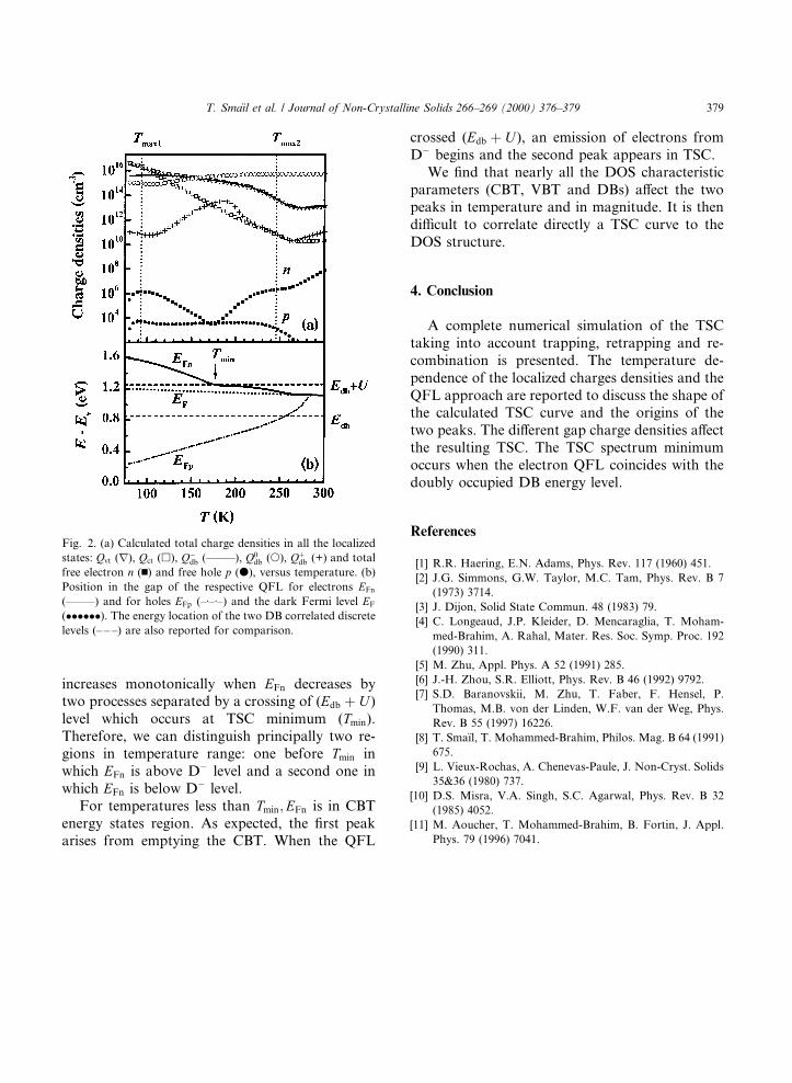
increases monotonically when EFn decreases bytwo processes separated by a crossing of (Edb � U )level which occurs at TSC minimum (Tmin).Therefore, we can distinguish principally two re-gions in temperature range: one before Tmin inwhich EFn is above Dÿ level and a second one inwhich EFn is below Dÿ level.
For temperatures less than Tmin;EFn is in CBTenergy states region. As expected, the ®rst peakarises from emptying the CBT. When the QFL
crossed (Edb � U ), an emission of electrons fromDÿ begins and the second peak appears in TSC.
We ®nd that nearly all the DOS characteristicparameters (CBT, VBT and DBs) a�ect the twopeaks in temperature and in magnitude. It is thendi�cult to correlate directly a TSC curve to theDOS structure.
4. Conclusion
A complete numerical simulation of the TSCtaking into account trapping, retrapping and re-combination is presented. The temperature de-pendence of the localized charges densities and theQFL approach are reported to discuss the shape ofthe calculated TSC curve and the origins of thetwo peaks. The di�erent gap charge densities a�ectthe resulting TSC. The TSC spectrum minimumoccurs when the electron QFL coincides with thedoubly occupied DB energy level.
References
[1] R.R. Haering, E.N. Adams, Phys. Rev. 117 (1960) 451.
[2] J.G. Simmons, G.W. Taylor, M.C. Tam, Phys. Rev. B 7
(1973) 3714.
[3] J. Dijon, Solid State Commun. 48 (1983) 79.
[4] C. Longeaud, J.P. Kleider, D. Mencaraglia, T. Moham-
med-Brahim, A. Rahal, Mater. Res. Soc. Symp. Proc. 192
(1990) 311.
[5] M. Zhu, Appl. Phys. A 52 (1991) 285.
[6] J.-H. Zhou, S.R. Elliott, Phys. Rev. B 46 (1992) 9792.
[7] S.D. Baranovskii, M. Zhu, T. Faber, F. Hensel, P.
Thomas, M.B. von der Linden, W.F. van der Weg, Phys.
Rev. B 55 (1997) 16226.
[8] T. Sma�õl, T. Mohammed-Brahim, Philos. Mag. B 64 (1991)
675.
[9] L. Vieux-Rochas, A. Chenevas-Paule, J. Non-Cryst. Solids
35&36 (1980) 737.
[10] D.S. Misra, V.A. Singh, S.C. Agarwal, Phys. Rev. B 32
(1985) 4052.
[11] M. Aoucher, T. Mohammed-Brahim, B. Fortin, J. Appl.
Phys. 79 (1996) 7041.
Fig. 2. (a) Calculated total charge densities in all the localized
states: Qvt (r), Qct (h), Qÿdb (±±±±±), Q0db (s), Q�db (+) and total
free electron n (n) and free hole p (d), versus temperature. (b)
Position in the gap of the respective QFL for electrons EFn
(±±±±±) and for holes EFp (±á±á±) and the dark Fermi level EF
(������). The energy location of the two DB correlated discrete
levels (± ± ±) are also reported for comparison.
T. Sma�õl et al. / Journal of Non-Crystalline Solids 266±269 (2000) 376±379 379
Recommended