Embed Size (px)
Citation preview
750
Leggere completamente questo manuale di istruzioni prima di iniziare l’installazione del prodotto.
Il simbolo evidenzia le note importanti per la sicurezza delle persone e l’integrità dell’automazione.
Il simbolo richiama l’attenzione sulle note riguardanti le caratteristiche od il funzionamento del prodotto.
Read this instruction manual to the letter before you begin to install the product.
Symbol highlights notes that are important for people’s safety and for the good condition of the automated
system.
Symbol draws your attention to the notes about the product’s characteristics or operation.
Lire ce manuel d’instructions dans son entier avant de commencer l’installation du produit.
Le symbole met en évidence les remarques pour la sécurité des personnes et le parfait état de l’automatisme.
Le symbole attire l’attention sur les remarques concernant les caractéristiques ou le fonctionnement du produit.
Vor der Installation des Produkts sind die Anweisungen vollständig zu lesen.
Mit dem Symbol sind wichtige Anmerkungen für die Sicherheit der Personen und den störungsfreien Betrieb der
Automation gekennzeichnet.
Mit dem Symbol wird auf Anmerkungen zu den Eigenschaften oder dem Betrieb des Produkts verwiesen.
Lean completamente este manual de instrucciones antes de empezar la instalación del producto.
El símbolo identifica notas importantes para la seguridad de las personas y para la integridad del automatismo.
El símbolo llama la atención sobre las notas relativas a las características o al funcionamiento del producto.
Lees deze instructiehandleiding helemaal door alvorens het product te installeren.
Het symbool is een aanduiding van opmerkingen die belangrijk zijn voor de veiligheid van personen en voor een
goede automatische werking.
Het symbool vestigt de aandacht op opmerkingen over de eigenschappen of de werking van het product.
Inserto Immagini - Pictures CollectionCollection de Figure - Cojunto de Imagenes
Photo Kollektion - Fotoverzameling
2
1
5
4
3
200152 ÷ 175
400
124
5
6
5
7
7
6
1
2
3
4
~ 270
~ 224
~470
5
min. 60
512
4
152÷
175
(100
)
(270)
250
450
470
90°
6/a
min. 60
512
4
152÷
175
(100
)
(270)
250
450
470
90°
6/b
ø 32 mm 7 8
min
. 155
0 ÷
max
. 284
0
9 10
245,6353
65
141,5 80,5
11
ø 5
12
255
362
max. 65
13
ø 30
14
min
. 100
15 16
C
A
B
D
CLOSE
OPEN
INT.
EXT.
17 18
19
MAX.
MIN.
20
1
2
21 22
min 250
23 24/a
24/b 25
26/a 26/b
27 28
29
�
EN
GLIS
H
Notes on reading the instructionsRead this instruction manual to the letter before you begin to install the product.
Symbol highlights notes that are important for people’s safety and for the good condition of the automated system.Symbol draws your attention to the notes about the product’s characteristics or operation.
INDEX
CE DECLARATION OF CONFORMITY FOR MACHINES .......................................................................................................... 2
WARNINGS FOR THE INSTALLER ........................................................................................................................................... 2
1 DESCRIPTION AND TECHNICAL SPECIFICATIONS .............................................................................................................. 3
2. INSTALLING THE AUTOMATED SYSTEM.............................................................................................................................. 3
2.1. PRELIMINARY CHECKS ............................................................................................................................................ 3
2.2. INSTALLING THE JACK ............................................................................................................................................. 3
2.3. INSTALLING THE HYDRAULIC CONTROL UNIT ........................................................................................................... 4
2.4. HYDRAULIC CONNECTION ...................................................................................................................................... 4
2.5. AIR BLEED OPERATIONS .......................................................................................................................................... 4
2.6. INSTALLING THE GATE ............................................................................................................................................. 5
3. OPERATION ..................................................................................................................................................................... 5
3.1. CHECKING THE SENSE OF ROTATION ....................................................................................................................... 5
3.2. SETTING OPERATION TIME ....................................................................................................................................... 5
3.3. SETTING THE ANTI-CRUSHING SYSTEM ..................................................................................................................... 5
4. TESTING THE AUTOMATED SYSTEM ................................................................................................................................... 5
5. MANUAL OPERATION ....................................................................................................................................................... 5
6. MAINTENANCE ................................................................................................................................................................ 5
�
EN
GLIS
H
1) ATTENTION!Toensurethesafetyofpeople,itisimportantthatyoureadallthefollowinginstructions.Incorrectinstallationorincorrectuseoftheproductcouldcauseseriousharmtopeople.
2) Carefullyreadtheinstructionsbeforebeginningtoinstalltheproduct.
3) Donotleavepackingmaterials(plastic,polystyrene,etc.)withinreachofchildrenassuchmaterialsarepotentialsourcesofdanger.
4) Storetheseinstructionsforfuturereference.
5) Thisproductwasdesignedandbuiltstrictlyfortheuseindicatedinthisdocumentation. Any other use, not expressly indicated here, couldcompromisethegoodcondition/operationoftheproductand/orbeasourceofdanger.
6) FAACdeclinesallliabilitycausedbyimproperuseoruseotherthanthatforwhichtheautomatedsystemwasintended.
7) Donotinstalltheequipmentinanexplosiveatmosphere:thepresenceofinflammablegasorfumesisaseriousdangertosafety.
8) ThemechanicalpartsmustconformtotheprovisionsofStandardsEN12604andEN12605.
Fornon-EUcountries,toobtainanadequatelevelofsafety,theStandardsmentioned above must be observed, in addition to national legalregulations.
9) FAAC is not responsible for failure to observe Good Technique intheconstructionoftheclosingelementstobemotorised,or foranydeformationthatmayoccurduringuse.
10) TheinstallationmustconformtoStandardsEN12453andEN12445.
Fornon-EUcountries,toobtainanadequatelevelofsafety,theStandardsmentioned above must be observed, in addition to national legalregulations.
11) Beforeattemptinganyjobonthesystem,cutoutelectricalpower.
12) Themainspowersupplyoftheautomatedsystemmustbefittedwithanall-poleswitchwithcontactopeningdistanceof3mmorgreater.Useofa6Athermalbreakerwithall-polecircuitbreakisrecommended.
13) Make sure that a differential switch with threshold of 0.03 A is fittedupstreamofthesystem.
14) Makesurethattheearthingsystemisperfectlyconstructedandconnectmetalpartsoftheclosuretoit.
15) Theautomatedsystemissuppliedwithanintrinsicanti-crushingsafetydeviceconsistingofatorquecontrol.Nevertheless,itstrippingthresholdmust be checked as specified in the Standards indicated at point10.
16) Thesafetydevices (EN12978standard) protectanydangerareasagainstmechanicalmovementRisks,suchascrushing,dragging,andshearing.
17) Useofatleastoneindicator-light(e.g.FAACLIGHT)isrecommendedforeverysystem,aswellasawarningsignadequatelysecuredtotheframestructure,inadditiontothedevicesmentionedatpoint“16”.
18) FAACdeclinesallliabilityasconcernssafetyandefficientoperationoftheautomatedsystem,ifsystemcomponentsnotproducedbyFAACareused.
19) Formaintenance,strictlyuseoriginalpartsbyFAAC.
20) Do not in any way modify the components of the automatedsystem.
21) Theinstallershallsupplyallinformationconcerningmanualoperationofthesystemincaseofanemergencyandshallhandovertotheuserthewarningshandbooksuppliedwiththeproduct.
22) Do not allow children or adults to stay near the product while it isoperating.
23) Keepradiocontrolsorotherpulsegeneratorsawayfromchildren,topreventtheautomatedsystemfrombeingactivatedinvoluntarily.
24) Transitispermittedonlywhentheautomatedsystemisidle.
25) Theusermustnotattemptanykindofrepairordirectactionwhateverandcontactqualifiedpersonnelonly.
26) Checkatleastevery6monthstheefficiencyofthesystem,particularlytheefficiencyofthesafetydevices(including,whereforeseen,theoperatorthrustforce)andofthereleasedevices.
27) Anything not expressly specified in these instructions is notpermitted.
WARNINGS FOR THE INSTALLERGENERALSAFETYOBLIGATIONS
CE DECLARATION OF CONFORMITY FOR MACHINES(DIRECTIVE �006/4�/EC)
Manufacturer: FAAC S.p.A.
Address: Via Calari, 10 - 40069 Zola Predosa BOLOGNA - ITALY
Declares that: Operator mod. 750
is built to be integrated into a machine or to be assembled with other machinery to create a machine under the provisions of Directive 2006/42/EC
conforms to the essential safety requirements of the following EEC directives: 2006/95/EC Low Voltage Directive 2004/108/EC Electromagnetic Compatibility Directive
and also declares that it is prohibited to put into service the machinery until the machine in which it will be integrated or of which it will become a component has been identified and declared as conforming to the conditions of Directive 2006/42/EEC and subsequent amendments.
Bologna, 01-07-2009 The Managing Director A. Marcellan
�
EN
GLIS
H
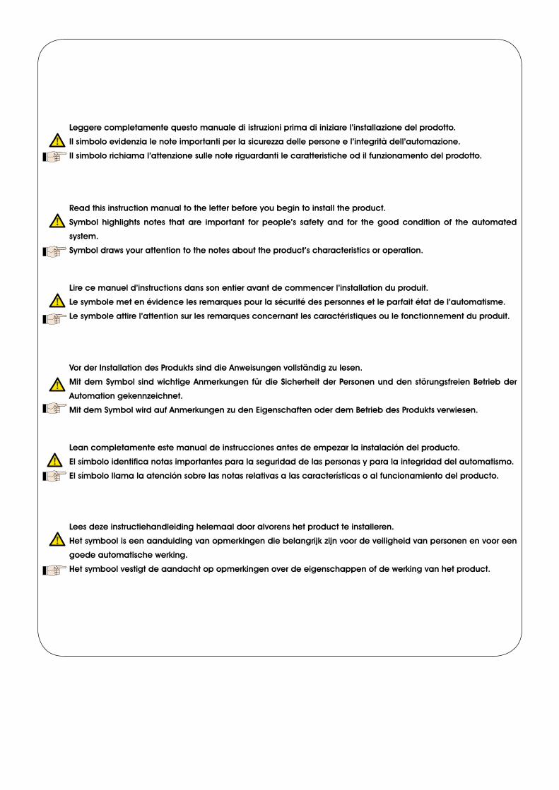
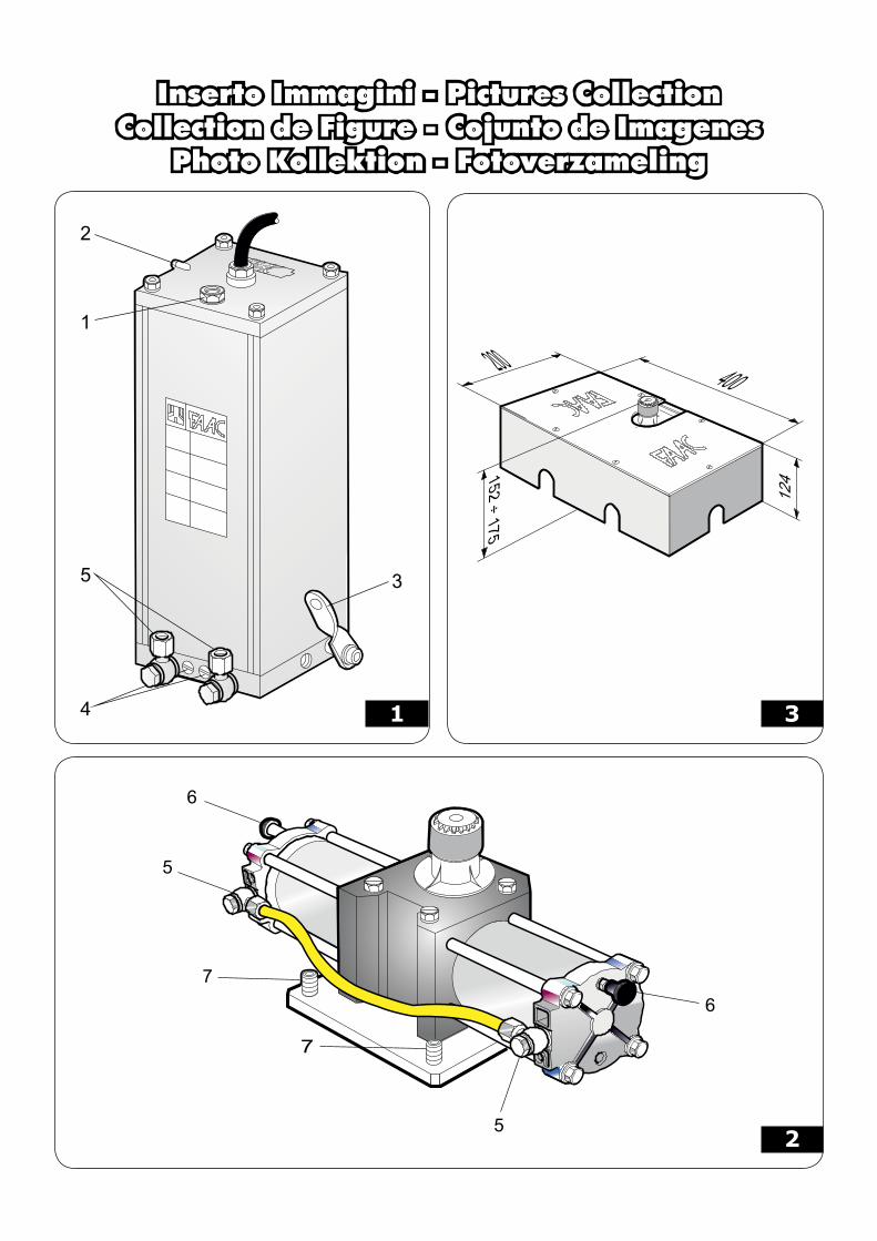
The 750 system makes it possible to automate, in a virtually invisible way, leaf gates.The automated system consists of an underground jack that transmits movement to the leaf and a hydraulic control unit that is usually fitted on the gate post. The two components are connected to each other using copper pipes or flexible tubes.
1 DESCRIPTION AND TECHNICAL SPECIFICATIONS
Fig.1-2
a Oilfillercapb breatherscrewc releaseleverd by-passscrewse hydraulicconnectionfittingsf airbleedscrewsg levellingsetscrews
Tab.1-TechnicalSpecificationsforhydrauliccontrolunit
AVAILABLE MODELS 750 CBAC 750 SB 750 SBSPower voltage (V ~/Hz) 230 (+6% -10%)/50Absorbed power (W) 220Absorbed current (A) 1Electric motor (rpm) 4-pole 1400 6-pole 960Thrust capacitor (uF/V) 8/400Winding thermal cutout (°C) 120
Duty cycle (cycles) (�) 45 30Amount of oil (l) 1Oil type FAAC HP OILOperating ambient temperature (°C) -20 °C +55
Protection class IP 55 (with appropriate cable leads/tube leads)
Weight (Kg) 7.5Pump capacity (l/min) 0,75 0,5Max leaf length (m) 1,8 2,5 3,5
Hydraulic lockwhen
opening and closing
no
(1) Exposure to direct sunlight can determine a drop in usage frequency.
Tab.2-Technicalspecificationsforhydraulicjack
AVAILABLE MODELSJACK �00°
JACK �80°
Max leaf weight (Kg) 800Max rotation angle (°) 118 200Max torque (Nm) 543 (750 CBAC/SB) - 272 (750 SBS)Angular speed (°/sec) 7,8° (750 CBAC/SB) - 5,2° (750 SBS)Amount of oil (l) 0,3 0,5Protection class IP 67Weight (Kg) 8 9
750 AUTOMATED SYSTEM2 INSTALLING THE AUTOMATED SYSTEM
2.1 PRELIMINARY CHECKS
For correct operation of the automated system, the existing gate structure, or the one to be built, must feature the following:
weight of each leaf no heavier than 800 kg;maximum length of each leaf must be 3.5 m (see tab.1);sturdy and rigid leaf structure;smooth and even movement of the leaves, without irregular friction during the entire stroke;good condition of the existing hinges;presence of mechanical limit stops.
We recommend that all blacksmith work be carried out before installing the automated system.The condition of the structure directly affects the reliability and safety of the automated system.
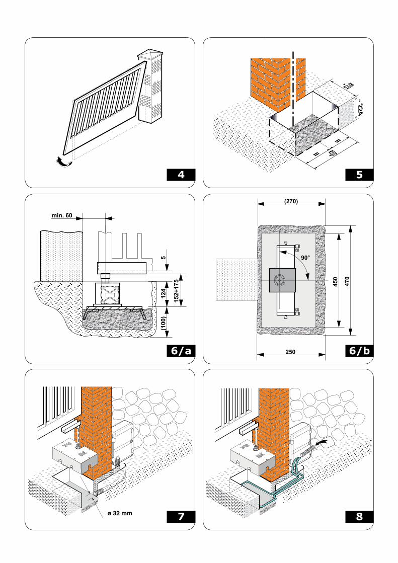
2.2 INSTALLING THE JACK
Fig.3-4-5-6/a-6/b-7-8-9-10
Following are possible work conditions and steps to take:a) existing gate with fixed hinges:
remove the gate;eliminate the bottom hinge.
If it is not possible to remove the gate, place a support shim under the leaf.b) Existing gate with adjustable hinges:
eliminate the bottom hinge;loosen the top hinge;rotate the leaf on the axis of the top hinge (fig.4).
c) Gate to build:install the top hinge of the leaf, preferably adjustable.
To avoid having to make niches at the base of the post, we recommend to keep a minimum distance between the rotation axis of the hinge and the post of 60 mm (fig.6/a).
••••
••
--
---
4
EN
GLIS
H
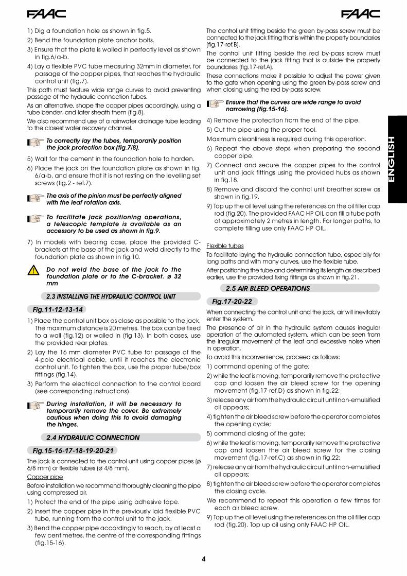
1)Digafoundationholeasshowninfig.5.
2)Bendthefoundationplateanchorbolts.
3)Ensurethattheplateiswalledinperfectlylevelasshowninfig.6/a-b.
4)LayaflexiblePVCtubemeasuring32mmindiameter,forpassageofthecopperpipes,thatreachesthehydrauliccontrolunit(fig.7).
This path must feature wide range curves to avoid preventing passage of the hydraulic connection tubes.As an alternative, shape the copper pipes accordingly, using a tube bender, and later sheath them (fig.8).We also recommend use of a rainwater drainage tube leading to the closest water recovery channel.
To correctly lay the tubes, temporarily position the jack protection box (fig.7/8).
5)Waitforthecementinthefoundationholetoharden.
6)Placethejackonthefoundationplateasshowninfig.6/a-b,andensurethatitisnotrestingonthelevellingsetscrews(fig.2-ref.7).
The axis of the pinion must be perfectly aligned with the leaf rotation axis.
To facilitate jack positioning operations, a telescopic template is available as an accessory to be used as shown in fig.9.
7) In models with bearing case, place the provided C-bracketsatthebaseofthejackandwelddirectlytothefoundationplateasshowninfig.10.
Do not weld the base of the jack to the foundation plate or to the C-bracket. ø 32 mm
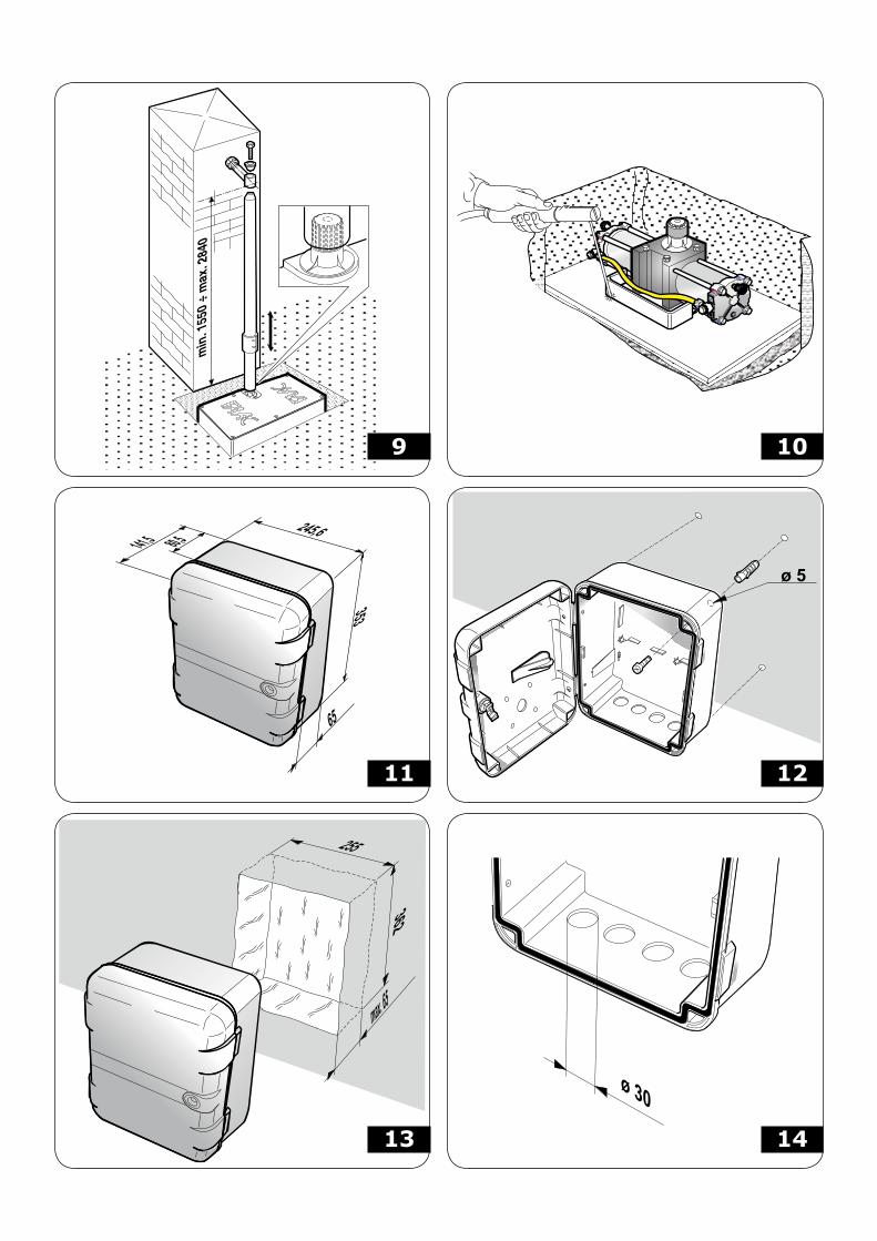
2.3 INSTALLING THE HYDRAULIC CONTROL UNIT
Fig.11-12-13-14
1)Placethecontrolunitboxascloseaspossibletothejack.Themaximumdistanceis20metres.Theboxcanbefixedtoawall(fig.12)orwalledin(fig.13).Inbothcases,usetheprovidedrearplates.
2)Laythe16mmdiameterPVCtubeforpassageof the4-pole electrical cable, until it reaches the electroniccontrolunit.Totightenthebox,usethepropertube/boxfittings(fig.14).
3)Performtheelectricalconnectiontothecontrolboard(seecorrespondinginstructions).
During installation, it will be necessary to temporarily remove the cover. Be extremely cautious when doing this to avoid damaging the hinges.
2.4 HYDRAULIC CONNECTION
Fig.15-16-17-18-19-20-21
The jack is connected to the control unit using copper pipes (ø 6/8 mm) or flexible tubes (ø 4/8 mm).Copper pipeBefore installation we recommend thoroughly cleaning the pipe using compressed air.
1)Protecttheendofthepipeusingadhesivetape.
2)InsertthecopperpipeinthepreviouslylaidflexiblePVCtube,runningfromthecontrolunittothejack.
3)Bendthecopperpipeaccordinglytoreach,byatleastafewcentimetres,thecentreofthecorrespondingfittings(fig.15-16).
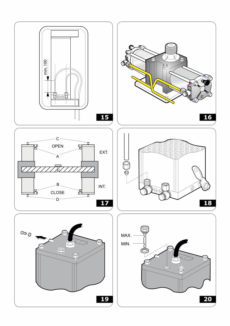
The control unit fitting beside the green by-pass screw must be connected to the jack fitting that is within the property boundaries (fig.17-ref.B).The control unit fitting beside the red by-pass screw must be connected to the jack fitting that is outside the property boundaries (fig.17-ref.A).These connections make it possible to adjust the power given to the gate when opening using the green by-pass screw and when closing using the red by-pass screw.
Ensure that the curves are wide range to avoid narrowing (fig.15-16).
4)Removetheprotectionfromtheendofthepipe.
5)Cutthepipeusingthepropertool.
Maximumcleanlinessisrequiredduringthisoperation.
6) Repeat the above steps when preparing the secondcopperpipe.
7) Connect and secure the copper pipes to the controlunitandjackfittingsusingtheprovidedhubsasshowninfig.18.
8)Removeanddiscardthecontrolunitbreatherscrewasshowninfig.19.
9)Topuptheoillevelusingthereferencesontheoilfillercaprod(fig.20).TheprovidedFAACHPOILcanfillatubepathofapproximately2metresinlength.Forlongerpaths,tocompletefillinguseonlyFAACHPOIL.
Flexible tubesTo facilitate laying the hydraulic connection tube, especially for long paths and with many curves, use the flexible tube.After positioning the tube and determining its length as described earlier, use the provided fixing fittings as shown in fig.21.
2.5 AIR BLEED OPERATIONS
Fig.17-20-22
When connecting the control unit and the jack, air will inevitably enter the system.The presence of air in the hydraulic system causes irregular operation of the automated system, which can be seen from the irregular movement of the leaf and excessive noise when in operation.To avoid this inconvenience, proceed as follows:
1)commandopeningofthegate;
2)whiletheleafismoving,temporarilyremovetheprotectivecap and loosen the air bleed screw for the openingmovement(fig.17-ref.D)asshowninfig.22;
3)releaseanyairfromthehydrauliccircuituntilnon-emulsifiedoilappears;
4)tightentheairbleedscrewbeforetheoperatorcompletestheopeningcycle;
5)commandclosingofthegate;
6)whiletheleafismoving,temporarilyremovetheprotectivecap and loosen the air bleed screw for the closingmovement(fig.17-ref.C)asshowninfig.22;
7)releaseanyairfromthehydrauliccircuituntilnon-emulsifiedoilappears;
8)tightentheairbleedscrewbeforetheoperatorcompletestheclosingcycle.
We recommend to repeat thisoperationa few times foreachairbleedscrew.
9)Topuptheoillevelusingthereferencesontheoilfillercaprod(fig.20).TopupoilusingonlyFAACHPOIL.
5
EN
GLIS
H
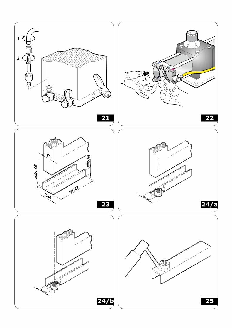
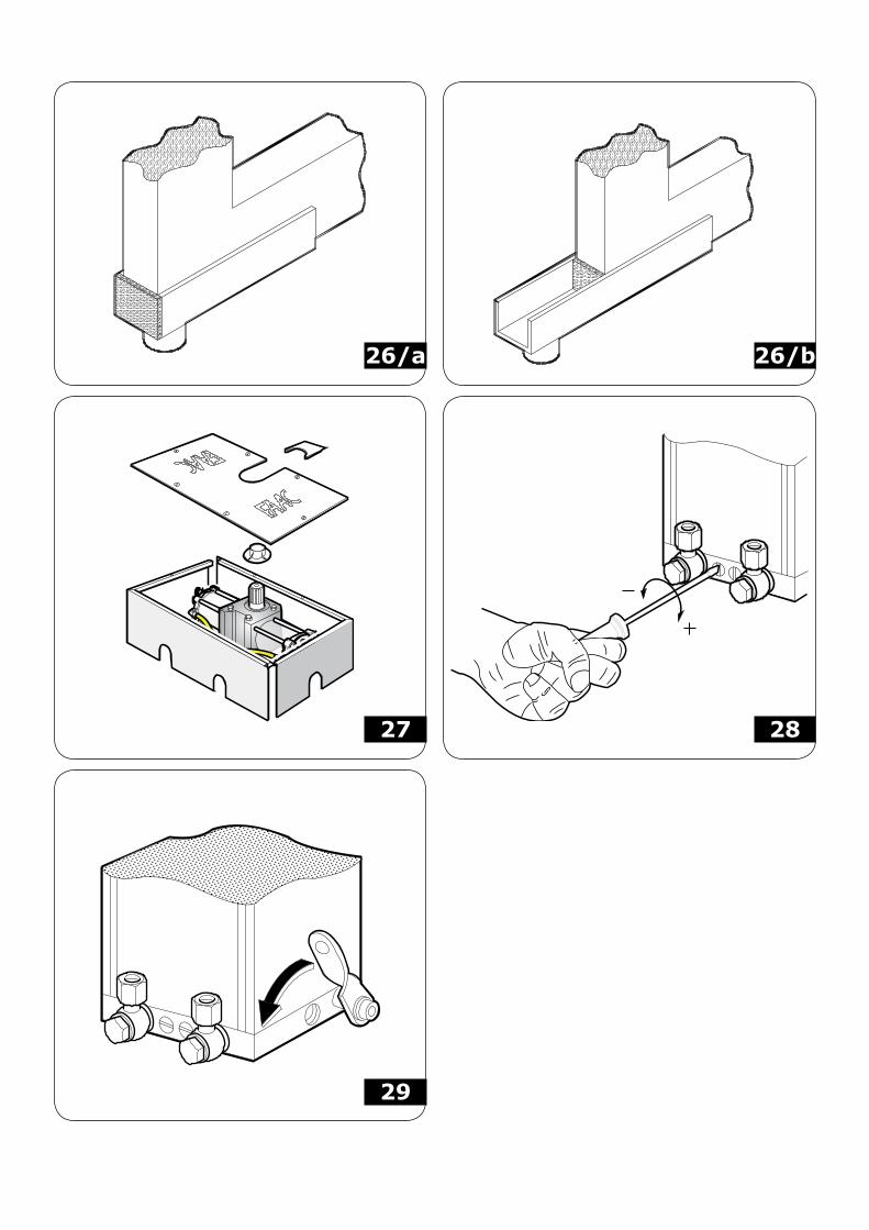
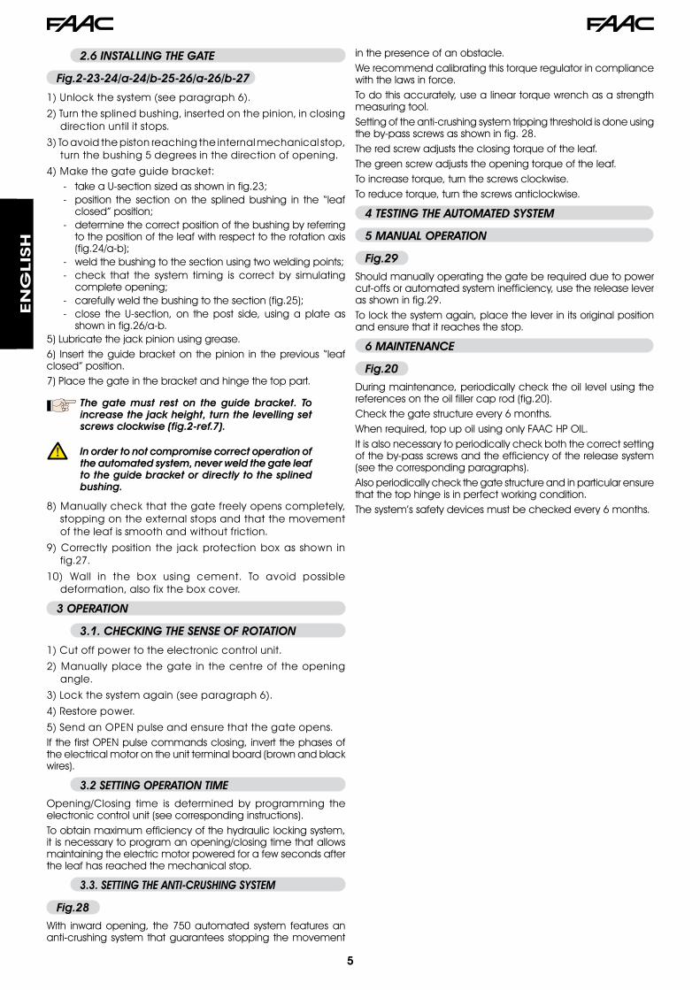
2.6 INSTALLING THE GATE
Fig.2-23-24/a-24/b-25-26/a-26/b-27
1)Unlockthesystem(seeparagraph6).
2)Turnthesplinedbushing,insertedonthepinion,inclosingdirectionuntilitstops.
3)Toavoidthepistonreachingtheinternalmechanicalstop,turnthebushing5degreesinthedirectionofopening.
4)Makethegateguidebracket:take a U-section sized as shown in fig.23;position the section on the splined bushing in the “leaf closed” position;determine the correct position of the bushing by referring to the position of the leaf with respect to the rotation axis (fig.24/a-b);weld the bushing to the section using two welding points;check that the system timing is correct by simulating complete opening;carefully weld the bushing to the section (fig.25);close the U-section, on the post side, using a plate as shown in fig.26/a-b.
5) Lubricate the jack pinion using grease.6) Insert the guide bracket on the pinion in the previous “leaf closed” position.7) Place the gate in the bracket and hinge the top part.
The gate must rest on the guide bracket. To increase the jack height, turn the levelling set screws clockwise (fig.2-ref.7).
In order to not compromise correct operation of the automated system, never weld the gate leaf to the guide bracket or directly to the splined bushing.
8)Manuallycheckthatthegatefreelyopenscompletely,stoppingontheexternalstopsandthatthemovementoftheleafissmoothandwithoutfriction.
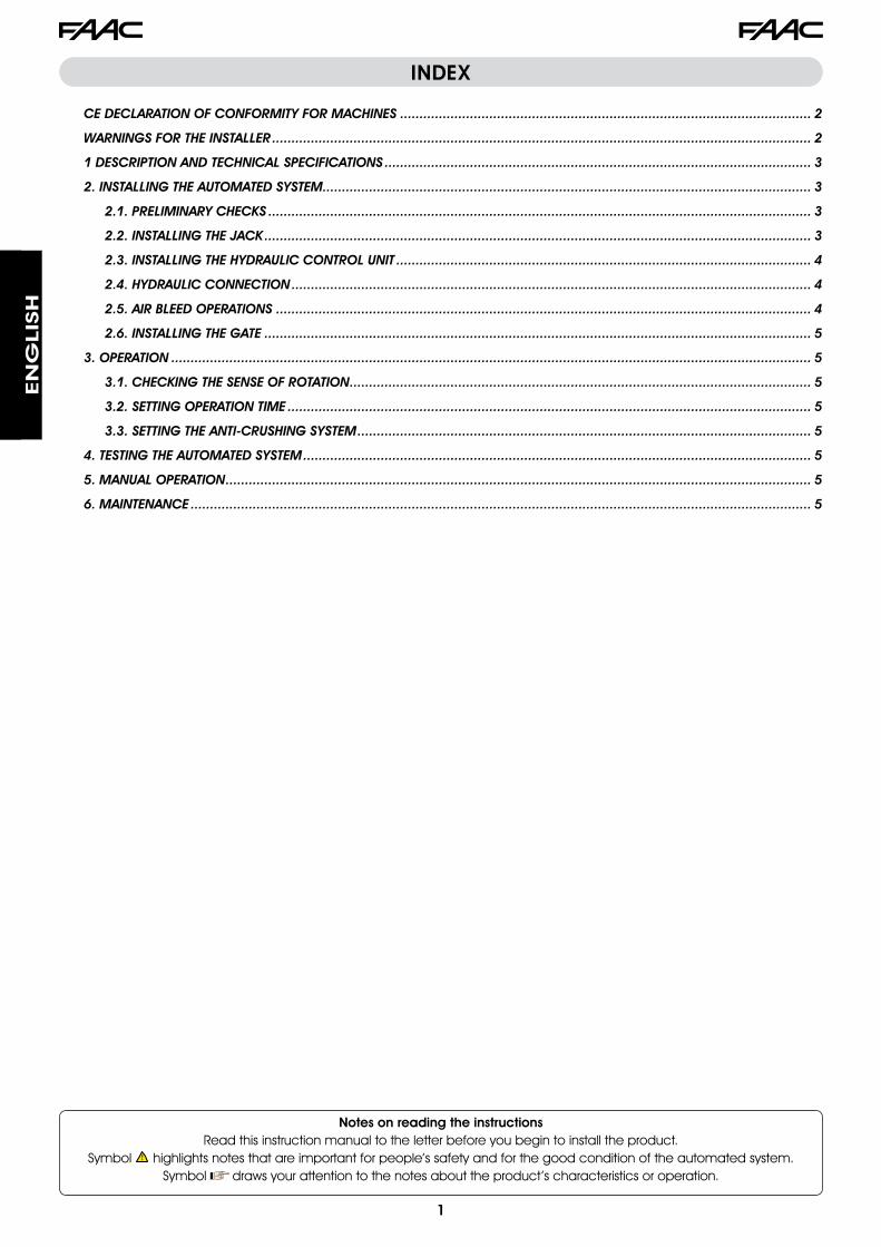
9)Correctlyposition the jackprotectionboxas shown infig.27.
10) Wall in the box using cement. To avoid possibledeformation,alsofixtheboxcover.
3 OPERATION
3.1. CHECKING THE SENSE OF ROTATION
1)Cutoffpowertotheelectroniccontrolunit.
2)Manuallyplacethegate inthecentreoftheopeningangle.
3)Lockthesystemagain(seeparagraph6).
4)Restorepower.
5)SendanOPENpulseandensurethatthegateopens.If the first OPEN pulse commands closing, invert the phases of the electrical motor on the unit terminal board (brown and black wires).
3.2 SETTING OPERATION TIME
Opening/Closing time is determined by programming the electronic control unit (see corresponding instructions).To obtain maximum efficiency of the hydraulic locking system, it is necessary to program an opening/closing time that allows maintaining the electric motor powered for a few seconds after the leaf has reached the mechanical stop.
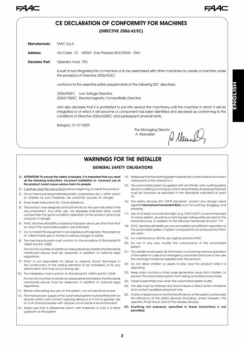
3.3. SETTING THE ANTI-CRUSHING SYSTEM
Fig.28
With inward opening, the 750 automated system features an anti-crushing system that guarantees stopping the movement
--
-
--
--
in the presence of an obstacle.We recommend calibrating this torque regulator in compliance with the laws in force.To do this accurately, use a linear torque wrench as a strength measuring tool.Setting of the anti-crushing system tripping threshold is done using the by-pass screws as shown in fig. 28.The red screw adjusts the closing torque of the leaf.The green screw adjusts the opening torque of the leaf.To increase torque, turn the screws clockwise.To reduce torque, turn the screws anticlockwise.
4 TESTING THE AUTOMATED SYSTEM
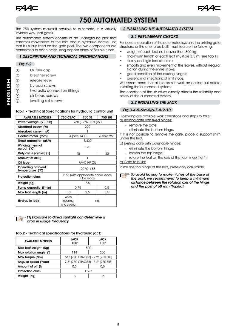
5 MANUAL OPERATION
Fig.29
Should manually operating the gate be required due to power cut-offs or automated system inefficiency, use the release lever as shown in fig.29.To lock the system again, place the lever in its original position and ensure that it reaches the stop.
6 MAINTENANCE
Fig.20
During maintenance, periodically check the oil level using the references on the oil filler cap rod (fig.20).Check the gate structure every 6 months.When required, top up oil using only FAAC HP OIL.It is also necessary to periodically check both the correct setting of the by-pass screws and the efficiency of the release system (see the corresponding paragraphs).Also periodically check the gate structure and in particular ensure that the top hinge is in perfect working condition.The system’s safety devices must be checked every 6 months.
Le descrizioni e le illustrazioni del presente manuale non sono impegnative. La FAAC si riserva il diritto, lasciando inalterate le caratteristiche essenziali dell’apparecchiatura, di apportare in qualunque momento e senza impegnarsi ad aggiornare la presente pubblicazione, le modifiche che essa ritiene convenienti per miglioramenti tecnici o per qualsiasi altra esigenza di carattere costruttivo o commerciale.
The descriptions and illustrations contained in the present manual are not binding. FAAC reserves the right, whilst leaving the main features of the equipments unaltered, to undertake any modifications it holds necessary for either technical or commercial reasons, at any time and without revising the present publication.
Les descriptions et les illustrations du présent manuel sont fournies à titre indicatif. FAAC se réserve le droit d’apporter à tout moment les modifications qu’elle jugera utiles sur ce produit tout en conservant les caractéristiques essentielles, sans devoir pour autant mettre à jour cette publication.
Die Beschreibungen und Abbildungen in vorliegendem Handbuch sind unverbindlich. FAAC behält sich das Recht vor, ohne die wesentlichen Eigenschaften dieses Gerätes zu verändern und ohne Verbindlichkeiten in Bezug auf die Neufassung der vorliegenden Anleitungen, technisch bzw. konstruktiv/kommerziell bedingte Verbesserungen vorzunehmen.
Las descripciones y las ilustraciones de este manual no comportan compromiso alguno. FAAC se reserva el derecho, dejando inmutadas las características esenciales de los aparatos, de aportar, en cualquier momento y sin comprometerse a poner al día la presente publicación, todas las modificaciones que considere oportunas para el perfeccionamiento técnico o para cualquier otro tipo de exigencia de carácter constructivo o comercial.
De beschrijvingen in deze handleiding zijn niet bindend. FAAC behoudt zich het recht voor op elk willekeurig moment de veranderingen aan te brengen die het bedrijf nuttig acht met het oog op technische verbeteringen of alle mogelijke andere productie- of commerciële eisen, waarbij de fundamentele eigenschappen van de apparaat gehandhaafd blijven, zonder zich daardoor te verplichten deze publicatie bij te werken.
FAAC S.p.A.Via Calari, 1040069 Zola Predosa (BO) - ITALIATel. 0039.051.61724 - Fax. 0039.051.758518www.faacgroup.com
732028 - Rev. A