Embed Size (px)
Citation preview
PoS(ICRC2019)428
A communication solution for portable detectors ofthe “Cosmic Ray Extremely DistributedObservatory”
Katarzyna Smelcerz∗
Institute of Telecomputing, Faculty of Physics, Mathematics and Computer Science, CracowUniversity of TechnologyE-mail: [email protected]
Konrad Kopanski1, Wojciech Noga2
1Institute of Nuclear Physics Polish Academy of Sciences, Radzikowskiego 152, Cracow, Poland2Cracow University of Technology, PolandE-mail: [email protected], E-mail: [email protected]
Mateusz Sułek1,2, Kevin Almeida Cheminant1
1Institute of Nuclear Physics Polish Academy of Sciences, Radzikowskiego 152, Cracow, Poland2Cracow University of Technology, PolandE-mail: [email protected] , E-mail: kevin.almeida-cheminantifj.edu.pl
for the CREDO Collaboration†
The search for Cosmic-Ray Ensembles (CRE), groups of correlated cosmic rays that might bedistributed over very large areas, even of the size of the planet, requires a globally spread anddense network of detectors, as proposed by the Cosmic-Ray Extremely Distributed Observatory(CREDO) Collaboration. This proposal motivates an effort towards exploring the potential ofusing even very much diversified detection technologies within one system, with detection unitslocated even in hard-to-reach places, where, nevertheless, the sensors could work independently– without human intervention. For these reasons we have developed a dedicated communicationsolution enabling the connection of many different types of detectors, in a range of environ-ments. The proposed data transmission system uses radio waves as an information carrier on the169MHz frequency band in a contrast to the typical commercially used frequencies in a IoT sys-tems (868MHz). The connectivity within the system is based on the star topology, which ensuresthe least energy consumption. The solution is now being prepared to being implemented using theprototype detection system based on the CosmicWatch open hardware design: a portable, pocketsize, and economy particle detector using the scintillation technique. Our prototype detector isequipped with a dedicated software that integrates it with the already operational CREDO serversystem.
36th International Cosmic Ray Conference -ICRC2019-July 24th - August 1st, 2019Madison, WI, U.S.A.
∗Speaker.†Full author list: http://credo.science/publications
c© Copyright owned by the author(s) under the terms of the Creative CommonsAttribution-NonCommercial-NoDerivatives 4.0 International License (CC BY-NC-ND 4.0). http://pos.sissa.it/
PoS(ICRC2019)428
Communication solution for CREDO portable detectors Katarzyna Smelcerz
1. Introduction
Due to the study of Cosmic-Ray Ensembles (CRE) in large areas and the correlation betweenspecific events, the project requires a large and widely dispersed research infrastructure. CREDOwants to rely not only on specialized detectors, such as those found in professional observatories(eg. Pierre Auger), which are available only to the scientific staff, but also on detectors that couldbe used by people who are not necessarily scientists (citizen science) [1]. Detectors that couldbe used in a large-scale experiment should be generally available, easy to use, and above all -cheap. This approach resulted in the implementation of smartphones in the CREDO project ascosmic ray detectors [2]. It is estimated that nowadays about 2.7 billion people are smartphoneusers [3]. Telephones as detectors unfortunately have quite limited "field of view" - the matrixhas an average size of 1/2.3”, also require permanent connection to the charger while operatingthe CREDO application. Thus, in a scenario in which we would like to "catch" particles in areasthat are difficult to access, i.e. forests or deserts, mobile phones will not pass the exam. Detectorsaccording to the scenario are to be deployed in both urbanized and uninhabited areas. This meansthat not everywhere will be access to the Internet, 3G or GSM.
An alternative to the GSM or WiFi network is ISM bandwidth, which does not require anyinfrastructure. Available ISM bands are 915 MHz, 868 MHz, 433 MHz and 169 MHz. The largestrange is obtained for the lowest frequencies, because the attenuation of the signal through obstaclesis proportional to the square of the frequency [4] (Formula 1.1). The aim was to select a universalcarrier that will provide communication in any environment. Therefore, the ISM 169 MHz bandwas selected for transmitting information in CREDO scenario.
L = Lx f 2 (1.1)
where Lx is constant characteristic to the material of the obstacle.
2. System Topology
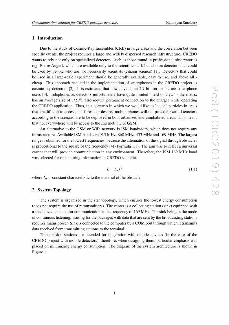
The system is organized in the star topology, which ensures the lowest energy consumption(does not require the use of retransmitters). The center is a collecting station (sink) equipped witha specialized antenna for communication at the frequency of 169 MHz. The sink being in the modeof continuous listening, waiting for the packages with data that are sent by the broadcasting stationsrequires mains power. Sink is connected to the computer by a COM port through which it transmitsdata received from transmitting stations to the terminal.
Transmission stations are intended for integration with mobile devices (in the case of theCREDO project with mobile detectors), therefore, when designing them, particular emphasis wasplaced on minimizing energy consumption. The diagram of the system architecture is shown inFigure 1.
1
PoS(ICRC2019)428
Communication solution for CREDO portable detectors Katarzyna Smelcerz
Figure 1: Topology of CREDO communication system
3. Radio waves as a carrier of wireless communication
There are many ready-made solutions on the market that provide wireless communication onISM bands, eg. LoRa and SigFox [5]. Unfortunately, the use of such solutions requires infras-tructure (receivers placed on masts), which are only available in larger cities. In this case, it is notpossible to use the communication system in non-urbanized areas. The range and mobility of thestation is a critical parameter when choosing the technology for the communication system for theCREDO project. During the system design, tests were carried out on starter-kit STM equipped withLoRa modules [6]. However, the LoRa protocol was not used because it was known that it couldnot be used in non-urbanized locations and only the LoRa’s modulation mode was tested. Unfor-tunately, no satisfactory coverage has been achieved ( 300 m in urban area). Similar tests wereconducted on starter-kit sets equipped with module SPIRIT1 [7], similarly, satisfactory test resultswere not obtained - in the built-up area the range was 100 m. Due to the fact that it is required toprovide communication for data readings from detectors both in urban and secluded areas, it finallybecame clear that it would be necessary to design our own broadcasting and receiving stations thatwere autonomous and dedicated to the project.
4. Transmission protocol
The system is based on one-way transmission of detectors to the receiving station. To avoidcollisions between individual transmissions, clock synchronization based on the DCF clock andtransmission in the "time slots" designated by the ID number of the transmitting stations, was used.In places where the DCF clock is unavailable, the transmitting station has the ability to emulatethe DCF signal. Each of the transmitting stations sends the frame to the sink in case of an event(particle detection) in the nearest "time slot". In addition to that, once an hour a status frame issent, including its GPS position. The DCF signal is transmitted on the 77.5 kHz frequency fromGermany and can be received within a radius of 2000 km. In places where DCF reception isnot possible, the receiving station emulates a DCF signal to synchronize the time in broadcastingstations. Each of the transmitting stations is assigned an ID number, which is an integer in the
2
PoS(ICRC2019)428
Communication solution for CREDO portable detectors Katarzyna Smelcerz
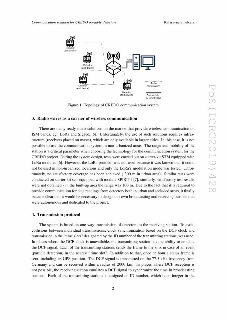
range < 1,+∞). In the experimental system, it was assumed that the transmitting stations withinone receiving unit is at most 60 pcs. and that they have ID numbers from 1 to 60. These ID numberscorrespond to time slots n, where n = IDnumber− 1, i.e. numbers from 0 to 59 corresponding tosubsequent minutes. The format of the frame sent by the sending station is presented on the Figure2.The end frame marker is not necessary, as a used radio module Semtech [8] recognizes the end
Figure 2: Frame format sent to the sink
of the frame on its own. The average life time of a battery at the sending station is presentedbelow is 2 years in a scenario where the data is sent once per hour from a detector, and the frametransmission time is 2.2 s. The battery lifetime was calculated by Formula 4.1.
batteryli f e[h] =B[mAh]I[mA]
(4.1)
where B is battery capacity, and I is average current.The average current was calculated by Formula 4.2.
I[A] =t[s]p[A]n
q[s](4.2)
where t is transmission time, p is power consumption when transmitting, n is number of framesper day and q is the number of seconds per day.
5. Antenna
Matching the right type and parameters of the antenna had a huge impact on the results ob-tained during the experiment. The experiment showed that the type of antenna not only affects therange but also the quality of the transmission. The basic parameters of the antenna are:
• Gain in relation to the reference antenna (dipole with a length of 12 wave)
• Impedance
• Directionality
Wavelength is another important parameter for determination of antenna length - the distancethat the radio wave travels during one complete cycle of the wave.
The project uses antennas with 50Ω impedance. The required length of the rod antenna shouldbe at least 1
4 of the radio wavelength. This means, the lower frequency, the longer antenna rodis required; it is a serious problem for mobile devices that should be miniaturised. Small sizeconstructions use antenna other than rods, which are shorter with good gain. The project uses
3
PoS(ICRC2019)428
Communication solution for CREDO portable detectors Katarzyna Smelcerz
transmitting antennas with a length of 110 mm and a gain of 2 dBi, while the rod antenna wouldhave to have a length of about 400 mm. The antenna in the receiving station does not have to beminiaturised. A full wave antenna (approx. 1500 mm long) and a gain of over 10 dBi was used.
6. The scope of the coverage experiment
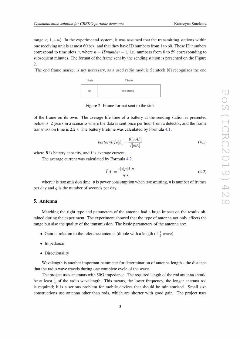
The experiment was conducted in the most difficult of possible conditions, including potentialscenarios of using the communication system in the CREDO project - meaning a high urban devel-opment in the city of Bytom. It should be remembered that the waves are reflected and absorbedby buildings, hence the range in urban areas is always smaller than in open areas. Figure 3 showsthe satellite map of the area in which the trials were carried out. About 20 tests were carried outwith various types of amplifiers and radio modules and antennas on the track marked in color. Thesystem consisted of one transmitting station, where the 8 bytes size frame was sent every 5 s, andone receiving station. The transmitting station (adapted to work with mobile devices) was mixedup at a walking pace. The person who carried out the experiment went for a walk with the sendingstation. Receiving station (sink) is marked with a yellow dot on the Figure 3. The sending stationis based on a standard implementation of the SX1276, transceiver LoRa [8]. The sink station isequipped with same type of the transceiver, however it has added very sensitive amplifier LNA.Places where communication failed - frames from the transmitting station did not reach the sink atall, are marked in red on the Figure 3. The best results have been obtained so far for the configura-tion presented in the current work. The system configuration may seem very simple, but it shouldbe noted that a more complicated configuration is not required to test the transmission range.
Figure 3: Satellite map, source: https://www.google.pl/maps
To carry out the communication coverage test, the transmitting station sends data about thetransmission, which are then collected at the terminal on the computer. The data is the device ID,f ramenumber, RSSI and SNR, where:
SNR (Signal Noise to Radio) is described by the Formula 6.1:
SNR(dB) = 10log10Psignal
Pnoise(6.1)
4
PoS(ICRC2019)428
Communication solution for CREDO portable detectors Katarzyna Smelcerz
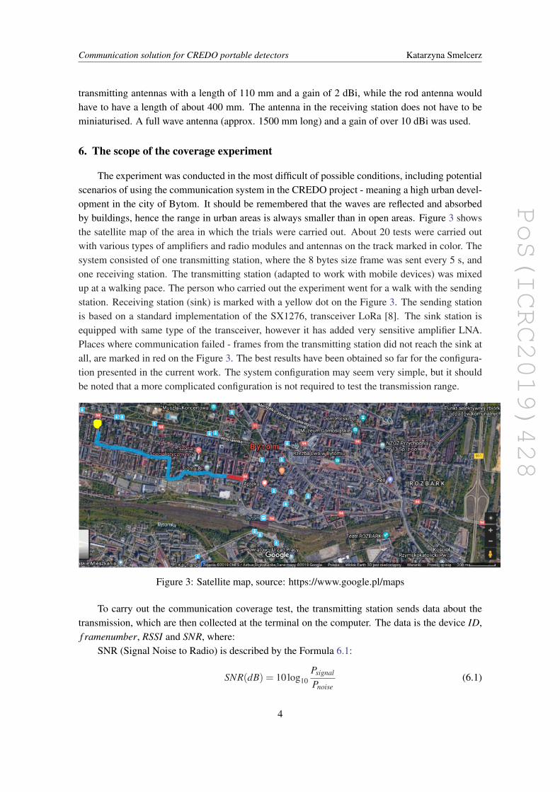
n ID frame RSSI SNR n ID frame RSSI SNR
392 12 597 -49 6 1 x 160 -69 -16393 12 598 -55 12 2 x 165 -70 -15394 12 599 -55 11 3 12 167 -69 -15395 12 600 -54 11 4 12 168 -69 -15396 12 601 -50 7 5 x 169 -69 -16397 12 602 -47 6 6 x x -69 -17398 12 603 -45 9 7 x 176 -69 -15399 12 604 -44 7 8 12 x -69 -16400 12 605 -44 7 9 x x -68 -17401 12 606 -44 7 10 x x -76 -17402 12 607 -44 6 11 x x -69 -16403 12 608 -44 7 12 12 182 -69 -15404 12 609 -55 7 13 x x -77 -17405 12 610 -52 12 14 12 186 -68 -17406 12 611 -53 11 15 12 4 -68 -17407 12 612 -52 11 16 x 189 -69 -15
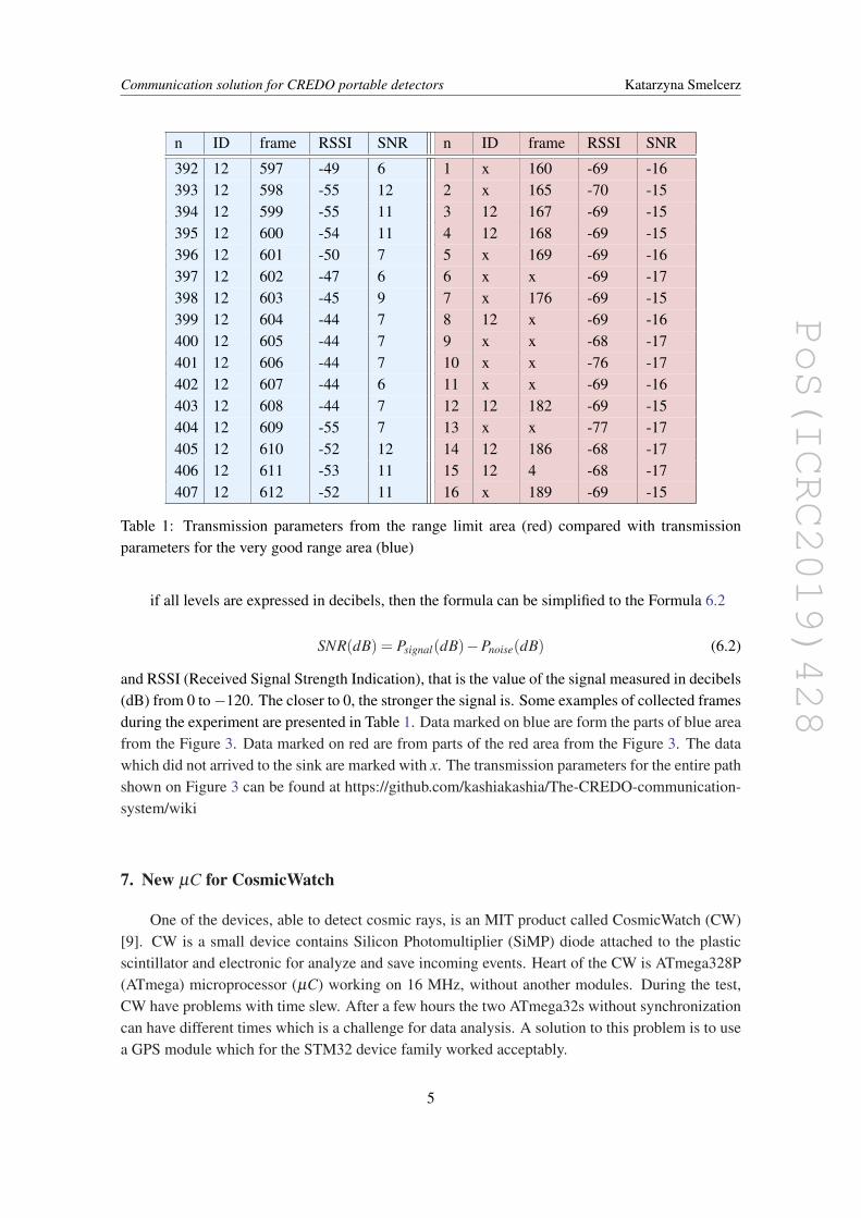
Table 1: Transmission parameters from the range limit area (red) compared with transmissionparameters for the very good range area (blue)
if all levels are expressed in decibels, then the formula can be simplified to the Formula 6.2
SNR(dB) = Psignal(dB)−Pnoise(dB) (6.2)
and RSSI (Received Signal Strength Indication), that is the value of the signal measured in decibels(dB) from 0 to −120. The closer to 0, the stronger the signal is. Some examples of collected framesduring the experiment are presented in Table 1. Data marked on blue are form the parts of blue areafrom the Figure 3. Data marked on red are from parts of the red area from the Figure 3. The datawhich did not arrived to the sink are marked with x. The transmission parameters for the entire pathshown on Figure 3 can be found at https://github.com/kashiakashia/The-CREDO-communication-system/wiki
7. New µC for CosmicWatch
One of the devices, able to detect cosmic rays, is an MIT product called CosmicWatch (CW)[9]. CW is a small device contains Silicon Photomultiplier (SiMP) diode attached to the plasticscintillator and electronic for analyze and save incoming events. Heart of the CW is ATmega328P(ATmega) microprocessor (µC) working on 16 MHz, without another modules. During the test,CW have problems with time slew. After a few hours the two ATmega32s without synchronizationcan have different times which is a challenge for data analysis. A solution to this problem is to usea GPS module which for the STM32 device family worked acceptably.
5
PoS(ICRC2019)428
Communication solution for CREDO portable detectors Katarzyna Smelcerz
As a test the STM32F446ZE (STM) on 180 MHz was used, with FGPMMOPA6H GPS mod-ule [10][11]. The internal two counters are used for timestamp for nanoseconds time frame andone timer for synchronization with GPS. In fact, the accuracy of time depends mainly from GPSmodule and conditions of GPS signal. Ideally this GPS module should have only 10 ns jitter, but infact this parameter is worse. Replacing µC in CW to STM with GPS module provide great increaseof performance and time precision than original solution of CW. STM is 11.25 times faster thanoriginal used ATmega and direct memory access (DMA) used in STM is solution for dead timecaused by communication with GPS module and data receiver (server) existing in ATmega.
While better software or using bespoke hardware such as FPGA can further improve the sys-tem it is not required. Our aim was to achieve an optimal price to performance ratio with suf-ficient timing precision, for that the µC solution was satisfactory. The software to connect CWand solution on STM with CREDO database is created software written in Python available athttps://github.com/credo-science/Credo-Desktop-Detector.
8. Conclusion and future work
To obtain a fully autonomous and mobile system for the detection of CRE, it is necessary tocreate our own low-power and mobile detector equipped with a reference real time clock. Un-fortunately, CosmicWatch detectors take too much electricity to power them with the battery, andsynchronization of their time base is not satisfactory for very accurate measurements. An importantaspect is also further improvement of the communication system. At the moment we are movingthrough 2D space; going down to lower frequencies, such as 27 MHz, would allow the possibilityof communication through the the ionospheric reflection of radio waves. This would allow thebypassing of obstacles (such as high buildings, ascents) in 3D space.
Assuming the detection station has access to a power supply, it would be worthwhile usingsimple systems to control the climatic conditions inside the measuring station. In the prototypestation the Peltier Modules and the water cooling system were used, to estimate its efficiency andreliability. Low power heaters were also used to dry the station interior and guarantee a safe andconvenient operating temperature, even in temperatures below zero (centigrade). The system isalso equipped with condensate pumps and an emergency ventilation system, based on compressedair, inside the chamber. Taking into account the physics of the detection process, the key elementis to ensure the appropriate conditions, mainly thermal ones. In addition, most plastic scintillatorssignificantly change their properties after repeated exposure to temperature changes above certainlimits. When using the detection technique based on semiconductor components (SiPM, ampli-fiers) in the analog path, the temperature differences can also significantly affect the measurementresults. For this purpose, it is necessary to conduct accurate thermal tests of the detectors used ina station, and to select the optimal measurement conditions for them, using active methods (con-trolled, autonomous climate chambers), as well as passive ones - radiators and housings allowingthe most favorable heat distribution.
By optimizing detection techniques for use in a stations with the lowest possible power con-sumption (battery, photovoltaic), it is necessary to choose the proper detection technique for change-able environmental conditions. It is therefore advisable to make thermal calibration of analog cir-cuits, and to take into account the results of calibration in subsequent data analysis. It is also
6
PoS(ICRC2019)428
Communication solution for CREDO portable detectors Katarzyna Smelcerz
necessary to test the influence of temperature on the scintillator parameters and to select the rightmaterial, guaranteeing the best results in a wide temperature range, while maintaining the lowestpossible price and highest durability.
References
[1] “We are all the Cosmic-Ray Extremely Distributed Observatory”, N. Dhital, et al. (CREDO Collab.),PoS (ICRC2017) 1078 [arXiv:1709.05196]
[2] “Cosmic-Ray Extremely Distributed Observatory: status and perspectives”,D.Góra, et al. (CREDOCollab.), Universe 2018,4(11) 111 .[arXiv:1810.10410]
[3] Statistic data https://www.statista.com/statistics/330695/number-of-smartphone-users-worldwide/,available on 5th July 2019
[4] “Urban Propagation Modeling For Wireless Systems”, William Mark Smith, Donald C. Cox, AReport submitted to the Army Research Office in fulfilment of Short Term Innovative Research(STIR) Grant DAAD19-03-1-0069
[5] “An Evaluation Of Low Power Wide Area Network Technologies For The Internet Of Things”, KeithE. Nolan, Wael Guibene, Mark Y. Kelly, 2016 International Wireless Communications and MobileComputing Conference (IWCMC)
[6] Technical documentation for B-L072Z-LRWAN1 LoRa R©/SigfoxTM Discovery kithttps://www.st.com/en/evaluation-tools/b-l072z-lrwan1.html, available on 5th July 2019
[7] Technical documentation for evaluation board based on the SPIRIT1https://www.st.com/en/evaluation-tools/steval-ikr002v1d.html, available on 5th July 2019
[8] Technical documentation for Semtech SX1276 137MHz to 1020MHz Long Range Low PowerTransceiver https://www.semtech.com/products/wireless-rf/lora-transceivers/sx1276, available on 5thJuly 2019
[9] CosmicWatch web page http://www.cosmicwatch.lns.mit.edu, available on 5th July 2019
[10] Technical documentation for STM32F446xC/E microcontrollerhttps://www.st.com/resource/en/datasheet/stm32f446ze.pdf, available on 5th July 2019
[11] Technical documentation for FGPMMOPA6H GPS Standalone Modulehttps://cdn-shop.adafruit.com/datasheets/GlobalTop-FGPMMOPA6H-Datasheet-V0A.pdf, availableon 5th July 2019
7