Embed Size (px)
Citation preview
Alexandru CIOCAN
Alexandru CIOCAN
Mémoire présenté en vue de l’obtention du grade de Docteur de L'Ecole nationale supérieure Mines-Télécom Atlantique Bretagne-Pays de la Loire - IMT Atlantique sous le sceau de l’Université Bretagne Loire
École doctorale : Sciences pour l'ingénieur, Géosciences, Architecture (SPIGA)
Discipline : Energétique, thermique Spécialité : Génie des procédés Unité de recherche : Génie des Procédés-Environnement-Agroalimentaire (GEPEA)
Soutenue le 17 octobre 2017 Thèse N° : 2017IMTA0028
Mémoire présenté en vue de l’obtention dugrade de Docteur de L'Ecole nationale supérieure Mines-Télécom Atlantique Bretagne-Pays de la Loire - IMT Atlantiquesous le sceau de l’Université Bretagne Loire
École doctorale : Sciences pour l'ingénieur, Géosciences, Architecture (SPIGA)
Discipline : Energétique, thermiqueSpécialité : Génie des procédés
Unité de recherche : Génie des Procédés-Environnement-Agroalimentaire (GEPEA)
Soutenue le (9)
Thèse N° : 2017IMTA0028
Contributions to energy storage using hybrid systems from alternative energy sources
JURYons aux systèmes de stockage d’énergie en
utilisant des systèmes hybrides à partir de
sources d’énergie alternatives
JURY
Rapporteurs : M. Liviu DRUGHEAN, Professeur d’Université Technique de Génie Civil Bucarest
M. Said ABBOUDI, Professeur d’Université de Technologie de Belfort-Montbéliard
Examinateurs :
M. Valentin APOSTOL, Lecteur d’Université Politehnica de Bucarest
M. Jean – Felix DURASTANTI, Professeur d’Université Paris Est Créteil
Mme Mariana-Florentina STEFANESCU, Professeur d’Université Politehnica de Bucarest
Invité(s) :
Directeur de Thèse : M. Tudor PRISECARU, Professeur d’Université Politehnica de Bucarest
Co-directeur de Thèse : M. Mohand TAZEROUT, Professeur d’Ecole des Mines de Nantes
Page 2 of 36
Contents
1. Introduction ........................................................................................................................ 3
2. Renewable Energy Sources overview ................................................................................ 5
3. The energy sector evolution ............................................................................................... 6
4. Energy storage solutions overview .................................................................................. 11
5. Mathematical modeling of a compressed air energy storage system ............................... 12
6. CAES system simulation in Matlab ................................................................................. 14
7. Experimental set-up representation .................................................................................. 17
8. Case study ........................................................................................................................ 24
9. The optimization production cost .................................................................................... 28
10. Thesis conclusions and perspectives ............................................................................. 31
Original contributions .............................................................................................................. 33
Bibliography ............................................................................................................................ 34
Page 3 of 36
1. Introduction
In the last two decades major changes have been seen in the way in which scientific community
and the decision factors have seen the future of the energy sector. Over the years there have
been several scenario predictions for the main fossil fuel as is going to run out somewhere to
the end of this century, considering the known reserves and is just a matter of time when they
run out, not if [1]. Even if some new reserves will be found, and help to extend the deadline
those reserves that will be discovered will be significantly smaller than that discovered in the
past. Obviously it’s well known that fossil fuel doesn’t represent a viable option and will be
less and less used and the fact that renewable energy sources will get an increasingly higher
attention.
The interest in energy storage is currently increasing, especially in order to integrate the
renewable energy sources to the grid and to satisfy consumers’ demands directly. Renewable
energy have great significance in the security of energy supply and can be used in the
conservation of fuel especially as raw materials in thermal power plants or for the road, rail,
maritime and air transport.
The biggest challenge with renewable energy is represented by their intermittent nature.
Referring only at solar and wind energy, those generate electric power only when the sun is
shining or the wind is blowing. The ways of storing energy for use on windless or sunless
periods must be found and must go up by the principle “you take when you can get it” [2]. How
to manage the RES fluctuating problem is the key issue of the development and utilization of
energy storage in the near future [3].
An important point underlying the integration and use of renewable sources is represented by
the necessity of reducing greenhouse gas emissions, given the fact that an important part of
contaminant released, represents the effect of the production processes of electricity and heat
from the thermal power plants (SO2, NO2, CO2, dust, slag, ash and thermal pollution).
A number of initiatives were taken globally with time thus in March 2007 the European Union
adopted a new policy regarding renewable energy target setting to obtain at least 20% of EU
energy needs from renewable sources by 2020. To achieve this goal the European Union
Commission has developed a series of new directives aimed at the energy industry and public
construction and private procedure. Among them we can include here: reducing greenhouse
emission (GHG) by 20% until 2020 in comparison with years ’90, increasing the share of
renewable energy (RES) to 20% of its energy sources by 2020, and reduction of global primary
consumption by 20% until 2020. Having these objectives summarized the program was called
20-20-20% [4]. Later in 2012 a new directive comes to support the projection made in 2007
and to assume once more the targets for primary energy consumption by 2020 [5].
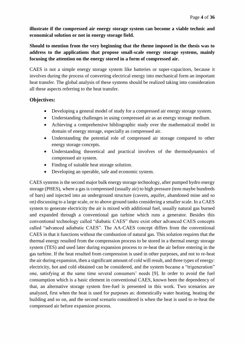
Aims and objectives
Energy storage is one of the main challenges in order to meet renewable energy technologies
due to their intermittent nature. So, the approach of the thesis is to realize contributions, to
Page 4 of 36
illustrate if the compressed air energy storage system can become a viable technic and
economical solution or not in energy storage field.
Should to mention from the very beginning that the theme imposed in the thesis was to
address to the applications that propose small-scale energy storage systems, mainly
focusing the attention on the energy stored in a form of compressed air.
CAES is not a simple energy storage system like batteries or super-capacitors, because it
involves during the process of converting electrical energy into mechanical form an important
heat transfer. The global analysis of these systems should be realized taking into consideration
all these aspects referring to the heat transfer.
Objectives:
Developing a general model of study for a compressed air energy storage system.
Understanding challenges in using compressed air as an energy storage medium.
Achieving a comprehensive bibliographic study over the mathematical model in
domain of energy storage, especially as compressed air.
Understanding the potential role of compressed air storage compared to other
energy storage concepts.
Understanding theoretical and practical involves of the thermodynamics of
compressed air system.
Finding of suitable heat storage solution.
Developing an operable, safe and economic system.
CAES systems is the second major bulk energy storage technology, after pumped hydro energy
storage (PHES), where a gas is compressed (usually air) to high pressure (tens maybe hundreds
of bars) and injected into an underground structure (cavern, aquifer, abandoned mine and so
on) discussing to a large scale, or to above ground tanks considering a smaller scale. In a CAES
system to generate electricity the air is mixed with additional fuel, usually natural gas burned
and expanded through a conventional gas turbine which runs a generator. Besides this
conventional technology called “diabatic CAES” there exist other advanced CAES concepts
called “advanced adiabatic CAES”. The AA-CAES concept differs from the conventional
CAES in that it functions without the combustion of natural gas. This solution requires that the
thermal energy resulted from the compression process to be stored in a thermal energy storage
system (TES) and used later during expansion process to re-heat the air before entering in the
gas turbine. If the heat resulted from compression is used in other purposes, and not to re-heat
the air during expansion, then a significant amount of cold will result, and three types of energy:
electricity, hot and cold obtained can be considered, and the system became a “trigeneration”
one, satisfying at the same time several consumers’ needs [9]. In order to avoid the fuel
consumption which is a basic element in conventional CAES, known been the dependency of
that, an alternative storage system free-fuel is presented in this work. Two scenarios are
analyzed, first when the heat is used for purposes as: domestically water heating, heating the
building and so on, and the second scenario considered is when the heat is used to re-heat the
compressed air before expansion process.
Page 5 of 36
2. Renewable Energy Sources overview
The renewable energy development as a global and clean energy is one of the main objectives
of worldwide energy policy that in the context of sustainable development aims to reduce the
fossil fuel consumption, to reduce the greenhouse emissions and to develop new viable
technologies in energy production [6], [7].
Today we primarily use fossil fuels to heat and power our homes and fuel our car even if in the
mobility sector has been made a lot of progress in more in electric vehicle and less in fuel cell
based vehicles. May be is convenient to use coal, oil and natural gas for meeting our energy
needs but these are limited and their recovery time is slower than consumption. Anyway, even
if the supply of fossil fuel will be unlimited, using renewable energy is better for the
environment, and usually are called clean or green.
The hydroelectric power plant is the most mature technology used in energy storage and
production from renewable energy sources. The capacity of a hydroelectric power plant is
incomparable with the capacity of any other powers plant which uses any other form of
renewable energy. Other technologies in converting renewable energy into electricity are
related to photovoltaic cells and concentrating solar power considering solar energy, wind
turbines considering wind energy, and at a lower scale but with some potential are technologies
based on biomass, geothermal energy and wave and tidal energy.
The biggest challenge related to a large share of renewable energy is caused by their
intermittent nature. Photovoltaic and wind turbine cannot produce energy when it is needed
and only when sun is shining and the wind is blowing. So, for this reason, renewable energy
sources cannot substitute the traditional energy generation power plant and replace them only
by the equivalent in wind turbines and photovoltaic panels. Since energy must be produced as
well in periods when renewable sources cannot cover the demand, traditional power plants
should be maintained in operation, and then the inconvenient is given by the fact that making
traditional power plant operational during peak demand hours make it to have a low economic
efficiency which is reflected into the cost. However a large share of renewable energy through
PV panels and wind turbines into the energy mix represents a “must have it” and this thing
could happen only by improving their coupling with other technical concepts that would ensure
a secured supply.
In 2015, the share of energy from renewable sources in gross final consumption of energy
reached 16.7 % in the European Union and the target to be reached by 2020 is a share of 20%
energy from renewable sources [source:Eurostat].
At the level of 2016 wind energy growth up to 486 GW, Hydropower up to 1064 GW, solar
energy up to 303 GW, biomass energy up to 296 GW and geothermal energy up to 13.2 GW.
Page 6 of 36
3. The energy sector evolution
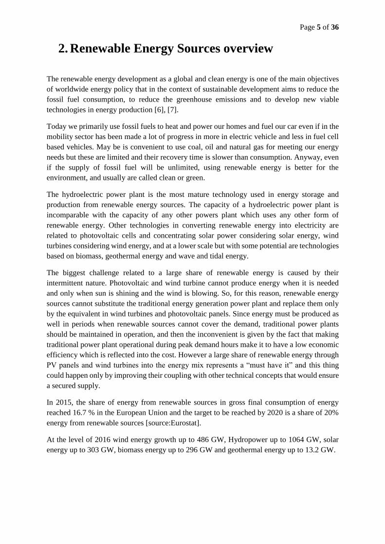
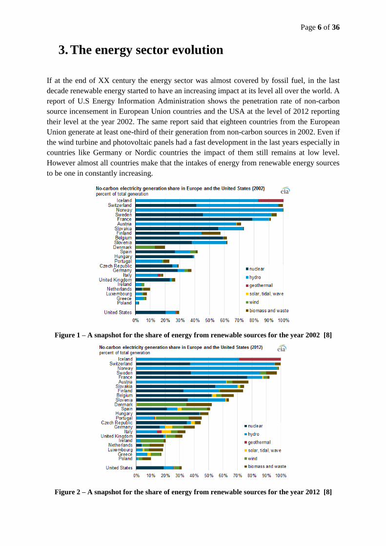
If at the end of XX century the energy sector was almost covered by fossil fuel, in the last
decade renewable energy started to have an increasing impact at its level all over the world. A
report of U.S Energy Information Administration shows the penetration rate of non-carbon
source incensement in European Union countries and the USA at the level of 2012 reporting
their level at the year 2002. The same report said that eighteen countries from the European
Union generate at least one-third of their generation from non-carbon sources in 2002. Even if
the wind turbine and photovoltaic panels had a fast development in the last years especially in
countries like Germany or Nordic countries the impact of them still remains at low level.
However almost all countries make that the intakes of energy from renewable energy sources
to be one in constantly increasing.
Figure 1 – A snapshot for the share of energy from renewable sources for the year 2002 [8]
Figure 2 – A snapshot for the share of energy from renewable sources for the year 2012 [8]
Page 7 of 36
France energy context
The French electricity sector is characterized by its high specificity when is compared with any
other from worldwide countries. As a consequence of the oil crises in 1974 France decide to
invest massively into the nuclear sector due to the fact that this energy is less dependent on the
economic events [9]. Since years 90’ nuclear energy in France represents more than 75% of
the electricity consumption. Most of the investments have been driven from the politically point
of view in such way to encourage technologies based on this type of energy and leaving very
little space to develop any other energy sources.
At present France is so addicted to the nuclear sector that the government decides that a new
nuclear reactor will be started only when an old one will be shutting down. This decision comes
immediately after Fukushima accident when the nuclear energy sector across the world was
faced to reconsider its energy policy. Many countries decided to turn their faces towards the
renewable energy sources and progressively to shut down their nuclear power plants. Germany
was one of the countries who react immediately and by the voice of its canceler Merkel
announced that all nuclear reactors would be closed until the end of 2022.
As well the policies pursued by the European Union which imposed renewable energy target
to be reached by 2020 for each country finds France in a very difficult situation having at the
end of 2014 only 9,100 MW power generation capacity from the wind and nearly 5,300 power
generation capacity from photovoltaic panels [10].
As any market mechanism the French power market is concentrated on: Electricity generation
largely dominated by EDF which on its turn is controlled by the French state, Transmission
and Distribution having as a system operator RTE and ERDF which are 100% owned by EDF.
The retail market is liberalized since 1999 when industrial sites became eligible to choose their
suppliers and in 2007 this option became possible as well for residential customers.
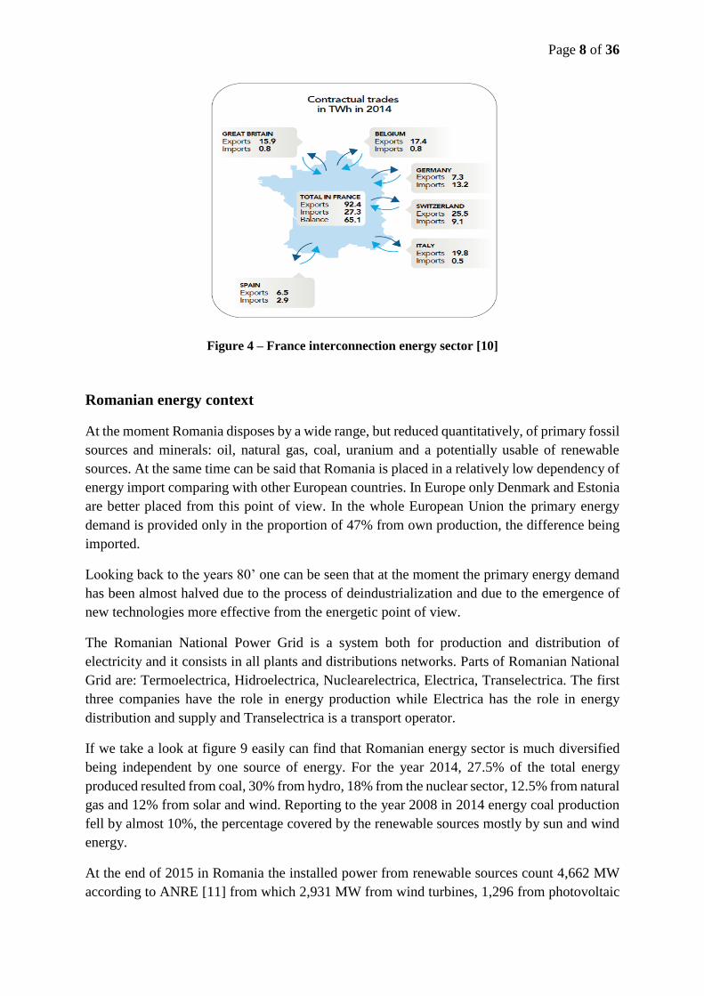
French energy sector is well interconnected with its neighbors. In figure 8 are presented exports
and imports for the year 2014 in which France are involved. One can be noted that France
exports electricity to Great Britain, Belgium, Switzerland Italy and Spain and mostly imports
from Germany, Switzerland and Spain.
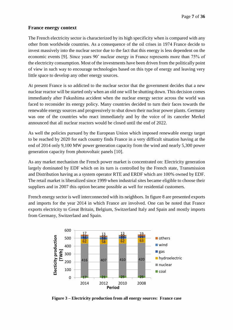
Figure 3 – Electricity production from all energy sources: France case
17 21 25 25
416 407 410 420
62 58 62 6316 19 22 2117 15 1017 13 13 19
0
100
200
300
400
500
600
2014 2012 2010 2008
Elec
tici
ty p
rod
uct
ion
[T
Wh
]
Period
others
wind
gas
hydroelectric
nuclear
coal
Page 8 of 36
Figure 4 – France interconnection energy sector [10]
Romanian energy context
At the moment Romania disposes by a wide range, but reduced quantitatively, of primary fossil
sources and minerals: oil, natural gas, coal, uranium and a potentially usable of renewable
sources. At the same time can be said that Romania is placed in a relatively low dependency of
energy import comparing with other European countries. In Europe only Denmark and Estonia
are better placed from this point of view. In the whole European Union the primary energy
demand is provided only in the proportion of 47% from own production, the difference being
imported.
Looking back to the years 80’ one can be seen that at the moment the primary energy demand
has been almost halved due to the process of deindustrialization and due to the emergence of
new technologies more effective from the energetic point of view.
The Romanian National Power Grid is a system both for production and distribution of
electricity and it consists in all plants and distributions networks. Parts of Romanian National
Grid are: Termoelectrica, Hidroelectrica, Nuclearelectrica, Electrica, Transelectrica. The first
three companies have the role in energy production while Electrica has the role in energy
distribution and supply and Transelectrica is a transport operator.
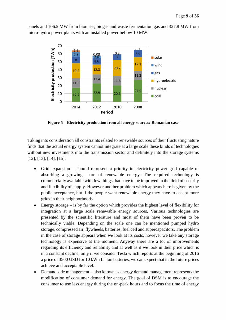
If we take a look at figure 9 easily can find that Romanian energy sector is much diversified
being independent by one source of energy. For the year 2014, 27.5% of the total energy
produced resulted from coal, 30% from hydro, 18% from the nuclear sector, 12.5% from natural
gas and 12% from solar and wind. Reporting to the year 2008 in 2014 energy coal production
fell by almost 10%, the percentage covered by the renewable sources mostly by sun and wind
energy.
At the end of 2015 in Romania the installed power from renewable sources count 4,662 MW
according to ANRE [11] from which 2,931 MW from wind turbines, 1,296 from photovoltaic
Page 9 of 36
panels and 106.5 MW from biomass, biogas and waste fermentation gas and 327.8 MW from
micro-hydro power plants with an installed power bellow 10 MW.
Figure 5 – Electricity production from all energy sources: Romanian case
Taking into consideration all constraints related to renewable sources of their fluctuating nature
finds that the actual energy system cannot integrate at a large scale these kinds of technologies
without new investments into the transmission sector and definitely into the storage systems
[12], [13], [14], [15].
Grid expansion – should represent a priority in electricity power grid capable of
absorbing a growing share of renewable energy. The required technology is
commercially available with few things that have to be improved in the field of security
and flexibility of supply. However another problem which appears here is given by the
public acceptance, but if the people want renewable energy they have to accept more
grids in their neighborhoods.
Energy storage – is by far the option which provides the highest level of flexibility for
integration at a large scale renewable energy sources. Various technologies are
presented by the scientific literature and most of them have been proven to be
technically viable. Depending on the scale one can be mentioned pumped hydro
storage, compressed air, flywheels, batteries, fuel cell and supercapacitors. The problem
in the case of storage appears when we look at its costs, however we take any storage
technology is expensive at the moment. Anyway there are a lot of improvements
regarding its efficiency and reliability and as well as if we look in their price which is
in a constant decline, only if we consider Tesla which reports at the beginning of 2016
a price of 3500 USD for 10 kWh Li-Ion batteries, we can expect that in the future prices
achieve and acceptable level.
Demand side management – also known as energy demand management represents the
modification of consumer demand for energy. The goal of DSM is to encourage the
consumer to use less energy during the on-peak hours and to focus the time of energy
17.722.9 20.6
27.5
11.611.4 11.6
11.219.2 12.3 20.2
17.18 8.6
78.96.2
2.60.3
0.21.60.08
0
10
20
30
40
50
60
70
2014 2012 2010 2008
Elec
tric
ity
pro
du
ctio
n [
TWh
]
Period
solar
wind
gas
hydroelectric
nuclear
coal
Page 10 of 36
use on off-peak periods such as nighttime and weekends. DSM doesn’t have as
objective to reduce the total energy consumption only the request at which the power
grid is supposed. So, various beneficial effects are resulted, through this could be
mentioned mitigating electrical system emergencies, reducing the number of blackout
and increasing the system reliability, possible benefits could also include reducing the
dependency on fossil fuel, reducing energy prices, reducing the investments in
generation, transmission and distribution networks. A solution is to use energy storage
units during off-peak periods and discharge them during on-peak periods. In DSM a
significant role is played by the integration of communications technology with the
power system and so in nowadays instead of DSM is more used the term of smart grid.
The aim of the smart grid is to lower energy costs and bring immediate benefits to the
consumer.
Discussions and Perspectives
At the moment all policy pursued in the energy sector is to focus more and more on renewable
energy sources. Nevertheless this transition to a green energy cannot be realized without the
development of storage facilities mainly at a large scale. Fluctuating nature of renewable
sources requires this with regard to have a balanced energy system.
Technically there are several storage technologies that have been proven their storage
capabilities. Of course there is space for further progress especially regarding efficiency and
lifetime. However the big step that storage technologies have to cross is to achieve an economic
feasibility.
Future progress in research and development of new solar concentrators and in the field of
energy storage technologies is expected to help the price go down in the same manner in which
happened in the case of photovoltaic cells and even in the case of wind turbines.
Renewables including wind and solar photovoltaic panels are increasingly competitive, even
in a lower fossil price regime. Heat resulted from renewable source can be a cost-competitive
option but not enjoys a sufficient policy attention. The policy should focus on creating the right
market and regulatory frameworks. Market and regulatory measures can influence the
expensive average and improve competitiveness.
A constant support for the market development and in the R&D sectors will reduce costs once
a technology becomes mature. If we take a look at the technology trends, we can see that PV
is extremely modular, easy and fast to install and accessible to everybody. The rapid cost
reductions have confirmed the fast learning rate of PV which leads to an increase in confidence
that sustained deployment will continually to reduce cost in the future.
Nowadays solar thermal energy based on concentrating solar power technologies can be used
in locations where the sun is very shiny and the skies are clear and where long range
transmission lines are used for transport to connect different areas. Solar thermal electricity is
usually used at large scale, but also small scale may find niche markets in isolated grids.
Page 11 of 36
4. Energy storage solutions overview
There are three main pylons on which it’s based the energy storage.
Energy storage should have an important asset for enhancing renewable energy
penetration.
Energy storage should represent an option for regulators as an effective option to
resolve issues regarding grid reliability.
Energy storage should have a huge impact in realizing smart-grids, especially in
developing of new electrical stations for transportation and for an optimal utilization of
electrical consumption [16].
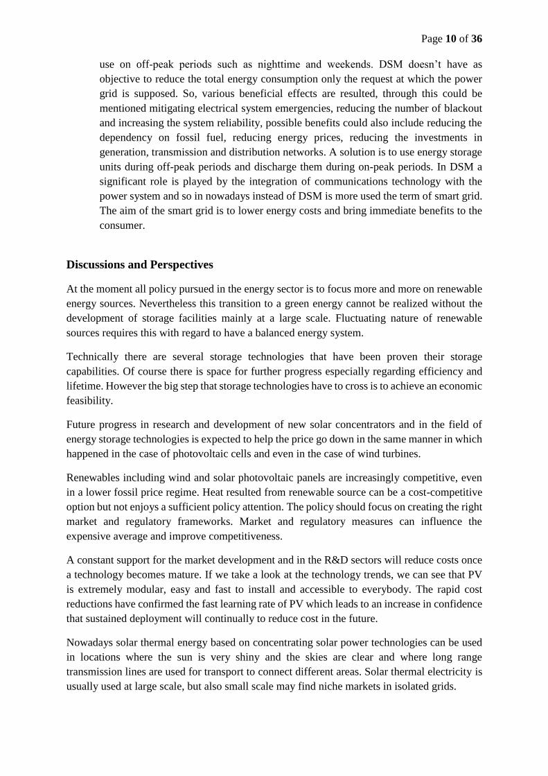
Figure 6 – Overview of electricity storage systems [17]
Unconcerned the storage medium, whether it’s about batteries, gas pressure, water
displacement and so on, the mostly technologies presented in the above figure follow the same
working principle in terms of charging, storage and discharging processes.
Charging mode – when the surplus of energy during off-peak hours is taken from renewable
sources and used to compress the air and stored in a storage vessel. If the system is connected
to the electrical grid it operates when there are off-peak hours and the price of electricity is low
usually in night period.
Discharging mode – when the energy is required and there are no other sources of energy the
compressed air is withdrawn from the storage reservoir and then expanded through an
expander, to drive a generator and providing peak power to the grid, or providing energy to the
final user.
Page 12 of 36
5. Mathematical modeling of a compressed air
energy storage system
CAES operating scenarios
A CAES technology includes five main components: one or more compressors, several
intercoolers, a storage vessel, one or more turbines, and one or more electric generators. During
air compression process compressor-motor consumes power from renewable sources or from
the grid to run the air compressor. Ambient air is compressed to a high pressure, cooled and
stored in a storage vessel for a certain period of time. When energy is needed the air is expanded
through an air engine or a turbine which drives a generator to produce electricity.
For a thermodynamic point of view there are three possible compression and expansion cases,
in which a CAES system can operate, under an isothermal, a polytropic or an adiabatic process.
This involves several scenarios in function of the storage pressure ratio and volume variations
[18], [19], [20]:
Variable inlet turbine pressure which varies with the storage vessel pressure.
Constant inlet turbine pressure by throttling the upstream air to a fixed pressure.
Maintaining a constant pressure by using methods that allow this [21], [22].
Some of this thee scenarios are more desirable then others functions of the applications
requirements. It’s well known the fact that in many cases a constant power is needed to be
supplied to the consumer.
The charging process
When the air at atmospheric pressure conditions is mechanically compressed by a compressor
from 1 bar to a higher pressure, than the transformation of the air is determined by the laws of
thermodynamics. In the charging process the air is taken from the atmosphere and compressed
by a compressor to a higher pressure. During a theoretical adiabatic or a more realistic
polytropic compression once the pressure rises the temperature rises, too.
Once the temperature rises appear several phenomena that are less desirable:
There is a decrease in compressor efficiency.
The vessel storage walls are exposed to thermal stress.
The gas density changes lead to a reduction in the amount of gas stored.
To eliminate all these difficulties is important to cool the air before to store it in the reservoir
through the use of heat exchangers. The resulted heat from compression process can be used
for other purposes or stored in a thermal energy storage system for later use.
Page 13 of 36
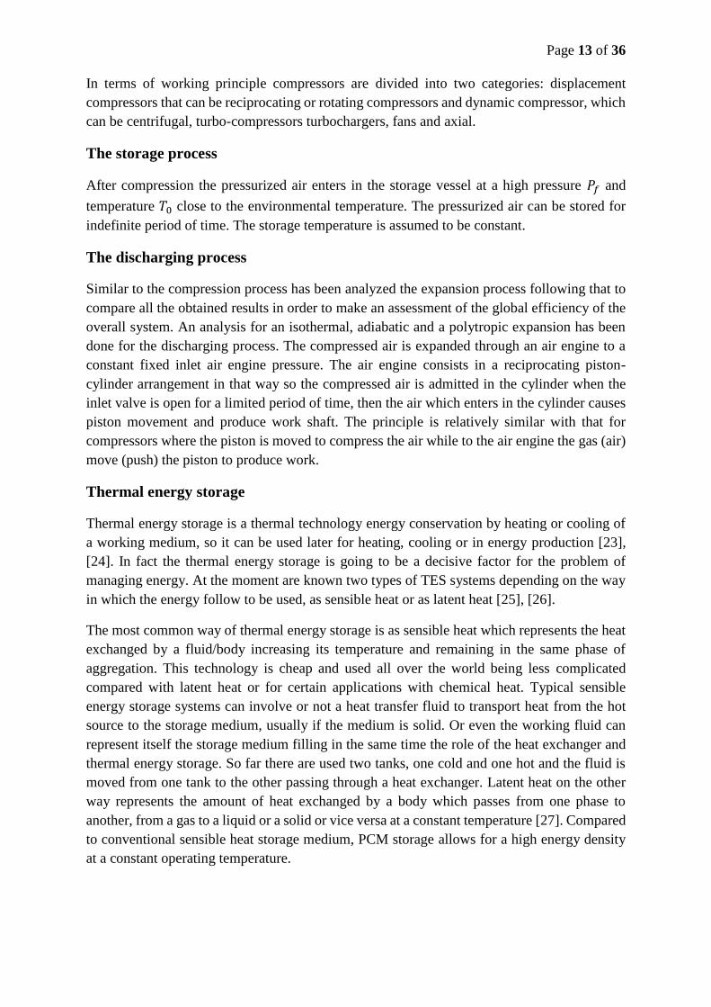
In terms of working principle compressors are divided into two categories: displacement
compressors that can be reciprocating or rotating compressors and dynamic compressor, which
can be centrifugal, turbo-compressors turbochargers, fans and axial.
The storage process
After compression the pressurized air enters in the storage vessel at a high pressure 𝑃𝑓 and
temperature 𝑇0 close to the environmental temperature. The pressurized air can be stored for
indefinite period of time. The storage temperature is assumed to be constant.
The discharging process
Similar to the compression process has been analyzed the expansion process following that to
compare all the obtained results in order to make an assessment of the global efficiency of the
overall system. An analysis for an isothermal, adiabatic and a polytropic expansion has been
done for the discharging process. The compressed air is expanded through an air engine to a
constant fixed inlet air engine pressure. The air engine consists in a reciprocating piston-
cylinder arrangement in that way so the compressed air is admitted in the cylinder when the
inlet valve is open for a limited period of time, then the air which enters in the cylinder causes
piston movement and produce work shaft. The principle is relatively similar with that for
compressors where the piston is moved to compress the air while to the air engine the gas (air)
move (push) the piston to produce work.
Thermal energy storage
Thermal energy storage is a thermal technology energy conservation by heating or cooling of
a working medium, so it can be used later for heating, cooling or in energy production [23],
[24]. In fact the thermal energy storage is going to be a decisive factor for the problem of
managing energy. At the moment are known two types of TES systems depending on the way
in which the energy follow to be used, as sensible heat or as latent heat [25], [26].
The most common way of thermal energy storage is as sensible heat which represents the heat
exchanged by a fluid/body increasing its temperature and remaining in the same phase of
aggregation. This technology is cheap and used all over the world being less complicated
compared with latent heat or for certain applications with chemical heat. Typical sensible
energy storage systems can involve or not a heat transfer fluid to transport heat from the hot
source to the storage medium, usually if the medium is solid. Or even the working fluid can
represent itself the storage medium filling in the same time the role of the heat exchanger and
thermal energy storage. So far there are used two tanks, one cold and one hot and the fluid is
moved from one tank to the other passing through a heat exchanger. Latent heat on the other
way represents the amount of heat exchanged by a body which passes from one phase to
another, from a gas to a liquid or a solid or vice versa at a constant temperature [27]. Compared
to conventional sensible heat storage medium, PCM storage allows for a high energy density
at a constant operating temperature.
Page 14 of 36
6. CAES system simulation in Matlab
A Matlab code has been written according to the theoretical model presented in chapter 5. The
modeling results obtained were validated on an experimental laboratory stand and all of these
are shown in tables and graphs in the following.
The assumptions listed below have been considered to simplify the analysis of the proposed
AA-CAES system:
The power provided by renewable energy sources through PV, CSP and/or wind turbine
is at least equal to the power consumed by the air compressor.
The compressed air is treated as an ideal gas.
All the kinetic and the potential energy are negligible.
The pressure drops in any of the system components are neglected.
The polytropic exponent n=1.2 (the average polytropic exponent obtained during the
experimental results varies between 1.18 and 1.2, at least 5 replies has been done, so
we choose then 1.2 in the theoretical simulations).
The temperature variation inside the storage vessel during both compression and
expansion processes is modeled by following an isothermal process.
The heat exchangers are modeled in such way to bring the air temperature after each
stage compression or expansion to a value close to the surrounding temperature.
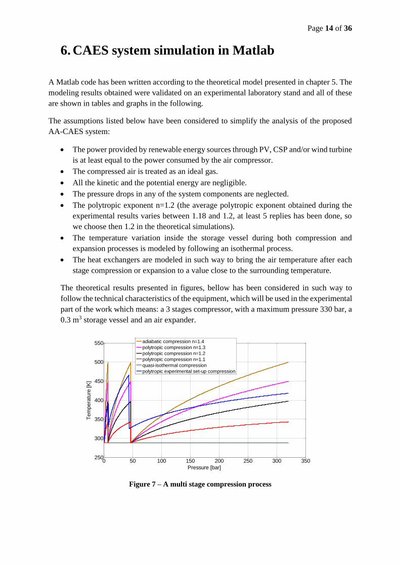
The theoretical results presented in figures, bellow has been considered in such way to
follow the technical characteristics of the equipment, which will be used in the experimental
part of the work which means: a 3 stages compressor, with a maximum pressure 330 bar, a
0.3 m3 storage vessel and an air expander.
Figure 7 – A multi stage compression process
0 50 100 150 200 250 300 350250
300
350
400
450
500
550
Pressure [bar]
Tem
pera
ture
[K
]
adiabatic compression n=1.4
polytropic compression n=1.3
polytropic compression n=1.2
polytropic compression n=1.1
quasi-isothermal compression
polytropic experimental set-up compression
Page 15 of 36
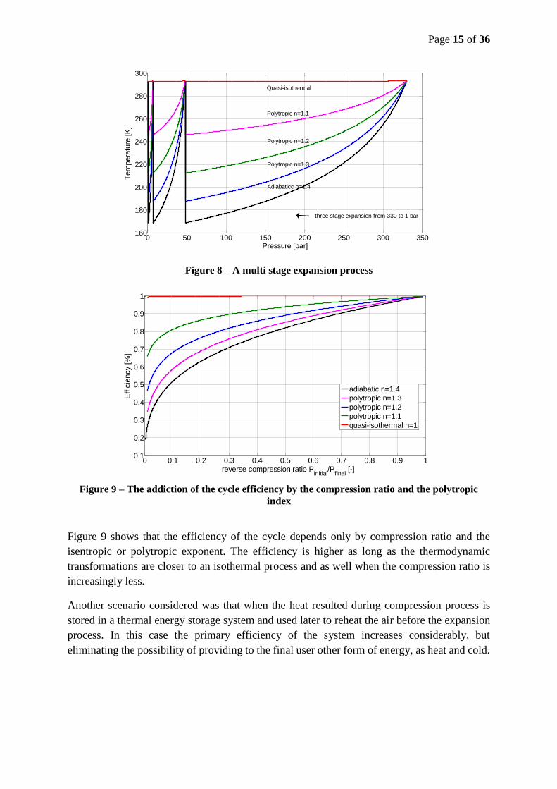
Figure 8 – A multi stage expansion process
Figure 9 – The addiction of the cycle efficiency by the compression ratio and the polytropic
index
Figure 9 shows that the efficiency of the cycle depends only by compression ratio and the
isentropic or polytropic exponent. The efficiency is higher as long as the thermodynamic
transformations are closer to an isothermal process and as well when the compression ratio is
increasingly less.
Another scenario considered was that when the heat resulted during compression process is
stored in a thermal energy storage system and used later to reheat the air before the expansion
process. In this case the primary efficiency of the system increases considerably, but
eliminating the possibility of providing to the final user other form of energy, as heat and cold.
0 50 100 150 200 250 300 350160
180
200
220
240
260
280
300
Pressure [bar]
Tem
pera
ture
[K
]
Quasi-isothermal
Polytropic n=1.2
Polytropic n=1.1
Polytropic n=1.3
Adiabaticc n=1.4
three stage expansion from 330 to 1 bar
0 0.1 0.2 0.3 0.4 0.5 0.6 0.7 0.8 0.9 10.1
0.2
0.3
0.4
0.5
0.6
0.7
0.8
0.9
1
reverse compression ratio Pinitial
/Pfinal
[-]
Effic
iency [%
]
adiabatic n=1.4
polytropic n=1.3
polytropic n=1.2
polytropic n=1.1
quasi-isothermal n=1
Page 16 of 36
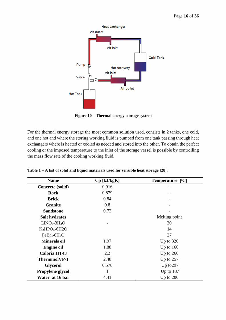
Figure 10 – Thermal energy storage system
For the thermal energy storage the most common solution used, consists in 2 tanks, one cold,
and one hot and where the storing working fluid is pumped from one tank passing through heat
exchangers where is heated or cooled as needed and stored into the other. To obtain the perfect
cooling or the imposed temperature to the inlet of the storage vessel is possible by controlling
the mass flow rate of the cooling working fluid.
Table 1 – A list of solid and liquid materials used for sensible heat storage [28].
Name Cp [kJ/kgK] Temperature [ ͦC]
Concrete (solid) 0.916 -
Rock 0.879 -
Brick 0.84 -
Granite 0.8 -
Sandstone 0.72 -
Salt hydrates
LiNO3-3H2O
K2HPO4-6H2O
FeBr3-6H2O
-
Melting point
30
14
27
Minerals oil 1.97 Up to 320
Engine oil 1.88 Up to 160
Caloria HT43 2.2 Up to 260
TherminolVP-1 2.48 Up to 257
Glycerol 0.578 Up to297
Propylene glycol 1 Up to 187
Water at 16 bar 4.41 Up to 200
Page 17 of 36
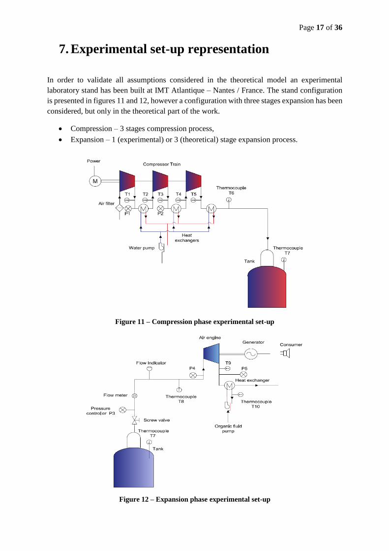
7. Experimental set-up representation
In order to validate all assumptions considered in the theoretical model an experimental
laboratory stand has been built at IMT Atlantique – Nantes / France. The stand configuration
is presented in figures 11 and 12, however a configuration with three stages expansion has been
considered, but only in the theoretical part of the work.
Compression – 3 stages compression process,
Expansion – 1 (experimental) or 3 (theoretical) stage expansion process.
Figure 11 – Compression phase experimental set-up
Figure 12 – Expansion phase experimental set-up
Page 18 of 36
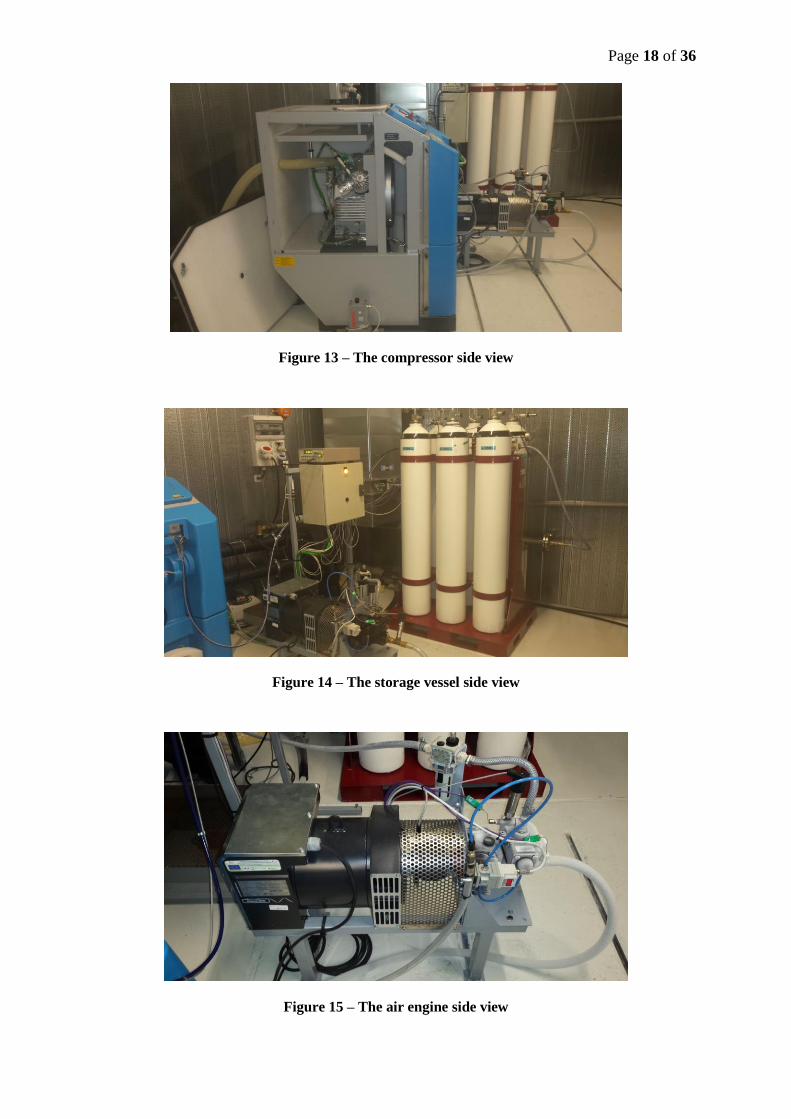
Figure 13 – The compressor side view
Figure 14 – The storage vessel side view
Figure 15 – The air engine side view
Page 19 of 36
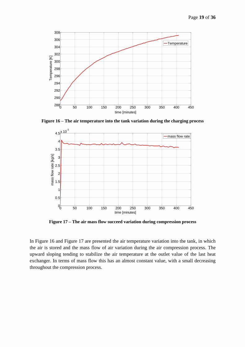
Figure 16 – The air temperature into the tank variation during the charging process
Figure 17 – The air mass flow succeed variation during compression process
In Figure 16 and Figure 17 are presented the air temperature variation into the tank, in which
the air is stored and the mass flow of air variation during the air compression process. The
upward sloping tending to stabilize the air temperature at the outlet value of the last heat
exchanger. In terms of mass flow this has an almost constant value, with a small decreasing
throughout the compression process.
0 50 100 150 200 250 300 350 400 450288
290
292
294
296
298
300
302
304
306
308
time [minutes]
Tem
pera
ture
[K
]
Temperature
0 50 100 150 200 250 300 350 400 4500
0.5
1
1.5
2
2.5
3
3.5
4
4.5x 10
-3
time [minutes]
mass flo
w r
ate
[kg/s
]
mass flow rate
Page 20 of 36
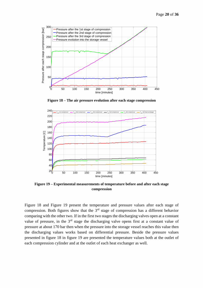
Figure 18 – The air pressure evolution after each stage compression
Figure 19 – Experimental measurements of temperature before and after each stage
compression
Figure 18 and Figure 19 present the temperature and pressure values after each stage of
compression. Both figures show that the 3rd stage of compression has a different behavior
comparing with the other two. If in the first two stages the discharging valves open at a constant
value of pressure, in the 3rd stage the discharging valve opens first at a constant value of
pressure at about 170 bar then when the pressure into the storage vessel reaches this value then
the discharging values works based on differential pressure. Beside the pressure values
presented in figure 18 in figure 19 are presented the temperature values both at the outlet of
each compression cylinder and at the outlet of each heat exchanger as well.
0 50 100 150 200 250 300 350 400 4500
50
100
150
200
250
300
Pre
ssure
after
each s
taqe c
om
pre
ssio
n [bar]
time [minutes]
Pressure after the 1st stage of compression
Pressure after the 2nd stage of compression
Pressure after the 3rd stage of compression
Pressure evolution into the storage vessel
0 50 100 150 200 250 300 350 400 45020
40
60
80
100
120
140
160
180
200
220
240
time [minutes]
Tem
pera
ture
[C
]
Tout
1st compressor Tout
2nd compressor Tout
3rd compressor Tin
2nd compressor Tin
3rd compressor Tout
3rd heat exchanger
Page 21 of 36
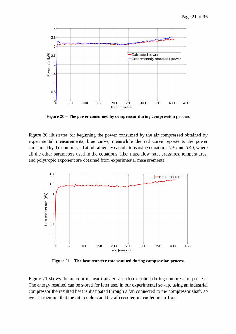
Figure 20 – The power consumed by compressor during compression process
Figure 20 illustrates for beginning the power consumed by the air compressed obtained by
experimental measurements, blue curve, meanwhile the red curve represents the power
consumed by the compressed air obtained by calculations using equations 5.36 and 5.40, where
all the other parameters used in the equations, like: mass flow rate, pressures, temperatures,
and polytropic exponent are obtained from experimental measurements.
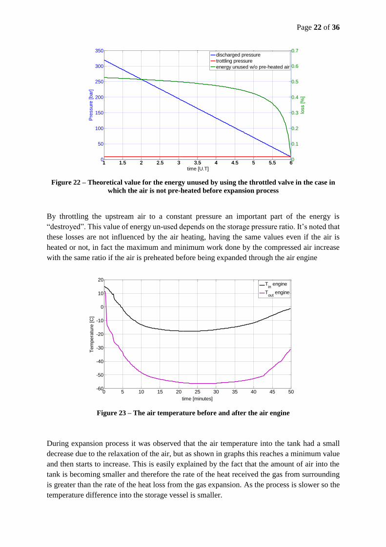
Figure 21 – The heat transfer rate resulted during compression process
Figure 21 shows the amount of heat transfer variation resulted during compression process.
The energy resulted can be stored for later use. In our experimental set-up, using an industrial
compressor the resulted heat is dissipated through a fan connected to the compressor shaft, so
we can mention that the intercoolers and the aftercooler are cooled in air flux.
0 50 100 150 200 250 300 350 400 4500
0.5
1
1.5
2
2.5
3
3.5
4
time [minutes]
Pow
er
rate
[kW
]
Calculated power
Experimentally measured power
0 50 100 150 200 250 300 350 400 4500
0.2
0.4
0.6
0.8
1
1.2
1.4
time [minutes]
Heat tr
ansf
er
rate
[kW
]
Heat transfer rate
Page 22 of 36
Figure 22 – Theoretical value for the energy unused by using the throttled valve in the case in
which the air is not pre-heated before expansion process
By throttling the upstream air to a constant pressure an important part of the energy is
“destroyed”. This value of energy un-used depends on the storage pressure ratio. It’s noted that
these losses are not influenced by the air heating, having the same values even if the air is
heated or not, in fact the maximum and minimum work done by the compressed air increase
with the same ratio if the air is preheated before being expanded through the air engine
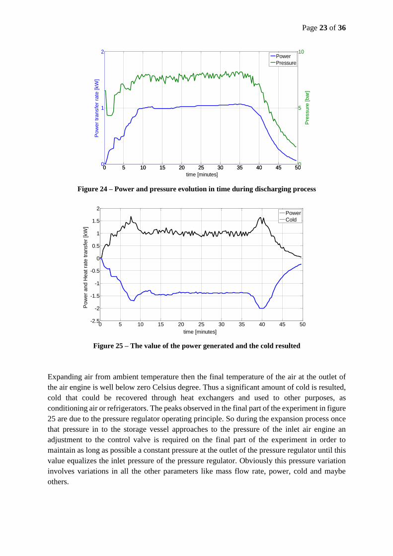
Figure 23 – The air temperature before and after the air engine
During expansion process it was observed that the air temperature into the tank had a small
decrease due to the relaxation of the air, but as shown in graphs this reaches a minimum value
and then starts to increase. This is easily explained by the fact that the amount of air into the
tank is becoming smaller and therefore the rate of the heat received the gas from surrounding
is greater than the rate of the heat loss from the gas expansion. As the process is slower so the
temperature difference into the storage vessel is smaller.
1 1.5 2 2.5 3 3.5 4 4.5 5 5.5 60
50
100
150
200
250
300
350
Pre
ssure
[bar]
time [U.T]
1 1.5 2 2.5 3 3.5 4 4.5 5 5.5 60
0.1
0.2
0.3
0.4
0.5
0.6
0.7
loss [%
]
discharged pressure
trottling pressure
energy unused w/o pre-heated air
0 5 10 15 20 25 30 35 40 45 50-60
-50
-40
-30
-20
-10
0
10
20
time [minutes]
Tem
pera
ture
[C
]
Tin
engine
Tout
engine
Page 23 of 36
Figure 24 – Power and pressure evolution in time during discharging process
Figure 25 – The value of the power generated and the cold resulted
Expanding air from ambient temperature then the final temperature of the air at the outlet of
the air engine is well below zero Celsius degree. Thus a significant amount of cold is resulted,
cold that could be recovered through heat exchangers and used to other purposes, as
conditioning air or refrigerators. The peaks observed in the final part of the experiment in figure
25 are due to the pressure regulator operating principle. So during the expansion process once
that pressure in to the storage vessel approaches to the pressure of the inlet air engine an
adjustment to the control valve is required on the final part of the experiment in order to
maintain as long as possible a constant pressure at the outlet of the pressure regulator until this
value equalizes the inlet pressure of the pressure regulator. Obviously this pressure variation
involves variations in all the other parameters like mass flow rate, power, cold and maybe
others.
0 5 10 15 20 25 30 35 40 45 500
1
2
time [minutes]
Pow
er
transfe
r ra
te [kW
]
0 5 10 15 20 25 30 35 40 45 500
5
10
Pre
ssure
[bar]
Power
Pressure
0 5 10 15 20 25 30 35 40 45 50-2.5
-2
-1.5
-1
-0.5
0
0.5
1
1.5
2
time [minutes]
Pow
er
and H
eat ra
te tra
nsfe
r [k
W]
Power
Cold
Page 24 of 36
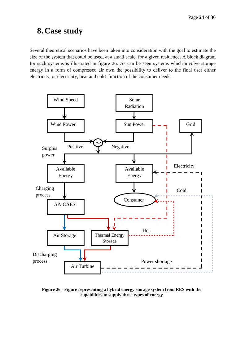
8. Case study
Several theoretical scenarios have been taken into consideration with the goal to estimate the
size of the system that could be used, at a small scale, for a given residence. A block diagram
for such systems is illustrated in figure 26. As can be seen systems which involve storage
energy in a form of compressed air own the possibility to deliver to the final user either
electricity, or electricity, heat and cold function of the consumer needs.
Figure 26 - Figure representing a hybrid energy storage system from RES with the
capabilities to supply three types of energy
Wind Speed
Wind Power
Solar
Radiation
Sun Power
Available
Energy
Thermal Energy
Storage
Available
Energy
Air Turbine
Surplus
power
Charging
process
power
Discharging
process
Positive Negative
Air Storage
Power shortage
Consumer
Grid
Cold
Hot
Electricity
AA-CAES
Page 25 of 36
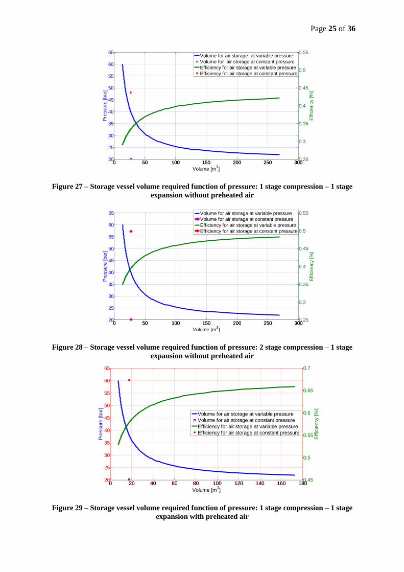
Figure 27 – Storage vessel volume required function of pressure: 1 stage compression – 1 stage
expansion without preheated air
Figure 28 – Storage vessel volume required function of pressure: 2 stage compression – 1 stage
expansion without preheated air
Figure 29 – Storage vessel volume required function of pressure: 1 stage compression – 1 stage
expansion with preheated air
0 50 100 150 200 250 30020
25
30
35
40
45
50
55
60
65
Pre
ssure
[bar]
Volume [m3]
0 50 100 150 200 250 3000.25
0.3
0.35
0.4
0.45
0.5
0.55
Effic
iency [%
]
Volume for air storage at variable pressure
Volume for air storage at constant pressure
Efficiency for air storage at variable pressure
Efficiency for air storage at constant pressure
0 20 40 60 80 100 120 140 160 18020
25
30
35
40
45
50
55
60
65
Pre
ssure
[bar]
Volume [m3]
0 20 40 60 80 100 120 140 160 1800.45
0.5
0.55
0.6
0.65
0.7
Effic
iency [%
]
Volume for air storage at variable pressure
Volume for air storage at constant pressure
Efficiency for air storage at variable pressure
Efficiency for air storage at constant pressure
Page 26 of 36
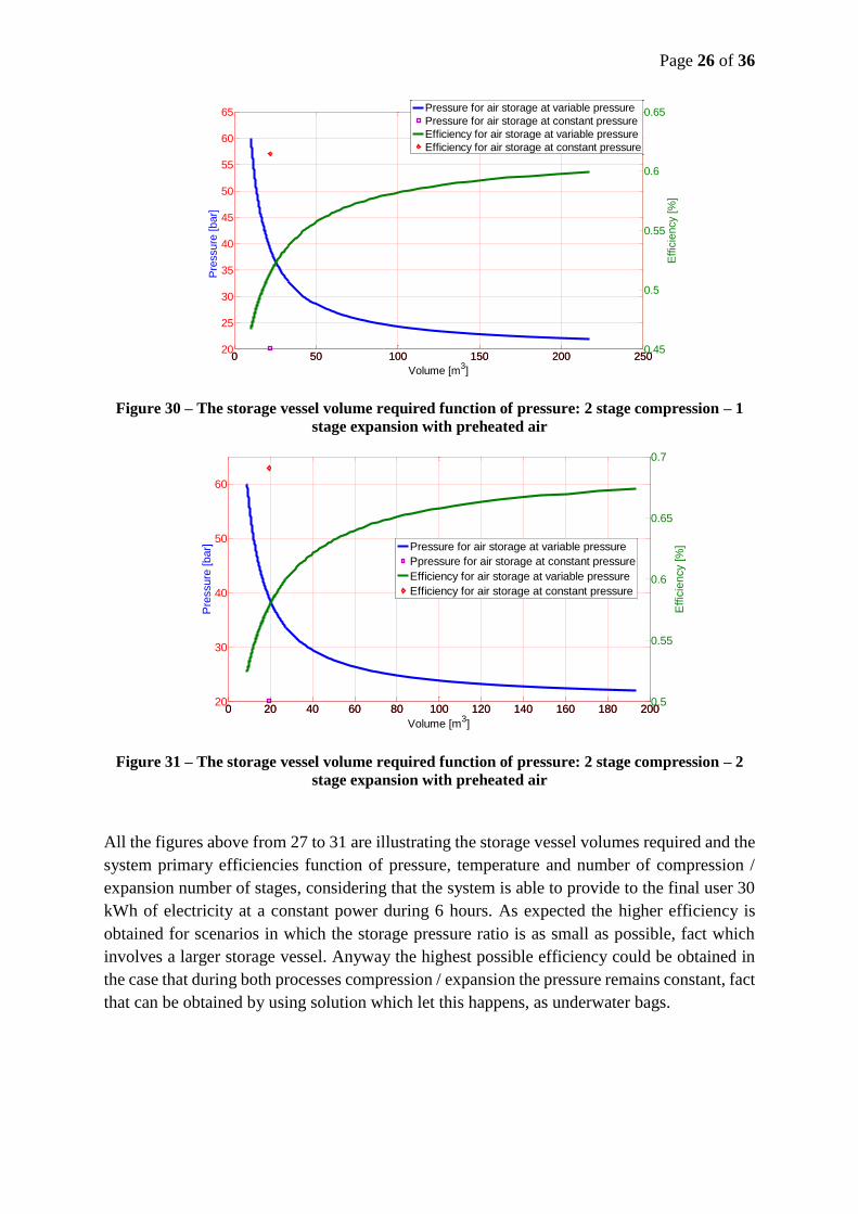
Figure 30 – The storage vessel volume required function of pressure: 2 stage compression – 1
stage expansion with preheated air
Figure 31 – The storage vessel volume required function of pressure: 2 stage compression – 2
stage expansion with preheated air
All the figures above from 27 to 31 are illustrating the storage vessel volumes required and the
system primary efficiencies function of pressure, temperature and number of compression /
expansion number of stages, considering that the system is able to provide to the final user 30
kWh of electricity at a constant power during 6 hours. As expected the higher efficiency is
obtained for scenarios in which the storage pressure ratio is as small as possible, fact which
involves a larger storage vessel. Anyway the highest possible efficiency could be obtained in
the case that during both processes compression / expansion the pressure remains constant, fact
that can be obtained by using solution which let this happens, as underwater bags.
0 50 100 150 200 25020
25
30
35
40
45
50
55
60
65
Pre
ssure
[bar]
Volume [m3]
0 50 100 150 200 2500.45
0.5
0.55
0.6
0.65
Effic
iency [%
]
Pressure for air storage at variable pressure
Pressure for air storage at constant pressure
Efficiency for air storage at variable pressure
Efficiency for air storage at constant pressure
0 20 40 60 80 100 120 140 160 180 20020
30
40
50
60
Pre
ssure
[bar]
Volume [m3]
0 20 40 60 80 100 120 140 160 180 2000.5
0.55
0.6
0.65
0.7
Effic
iency [%
]Pressure for air storage at variable pressure
Ppressure for air storage at constant pressure
Efficiency for air storage at variable pressure
Efficiency for air storage at constant pressure
Page 27 of 36
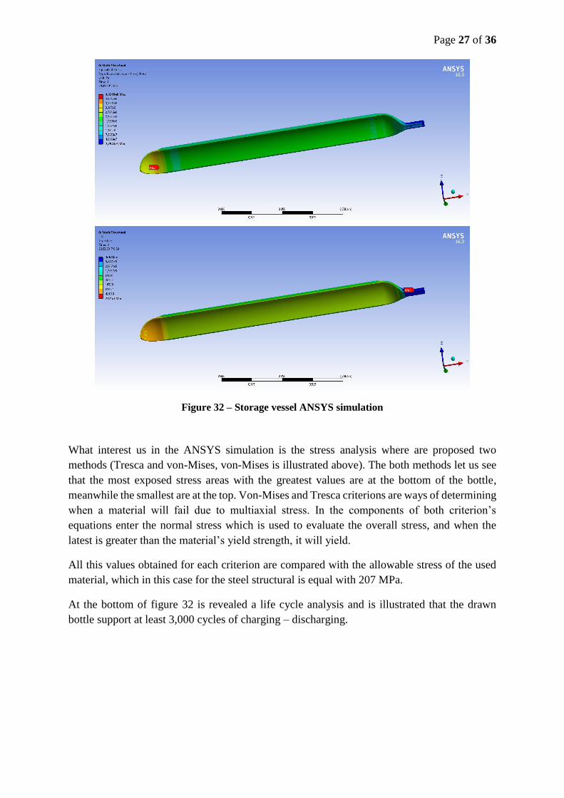
Figure 32 – Storage vessel ANSYS simulation
What interest us in the ANSYS simulation is the stress analysis where are proposed two
methods (Tresca and von-Mises, von-Mises is illustrated above). The both methods let us see
that the most exposed stress areas with the greatest values are at the bottom of the bottle,
meanwhile the smallest are at the top. Von-Mises and Tresca criterions are ways of determining
when a material will fail due to multiaxial stress. In the components of both criterion’s
equations enter the normal stress which is used to evaluate the overall stress, and when the
latest is greater than the material’s yield strength, it will yield.
All this values obtained for each criterion are compared with the allowable stress of the used
material, which in this case for the steel structural is equal with 207 MPa.
At the bottom of figure 32 is revealed a life cycle analysis and is illustrated that the drawn
bottle support at least 3,000 cycles of charging – discharging.
Page 28 of 36
9. The optimization production cost
We have to mention that the inlet pressure of the expander for the existing CAES high pressure
(45 – 70 bar) is much higher than the equivalent for a gas turbine, so a conventional gas turbine
can only be used as the low-pressure expander. Even on the market from the best knowledge
of the author the gas expanders, air engines or turbines, operate at low values of pressure.
4,44%
6,84%
36,46%
52,26%
Compressor
Storage vessel
Air engine
Generator
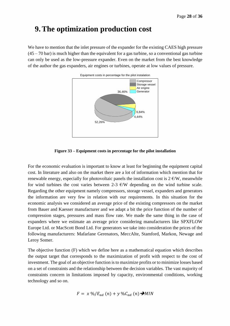
Equipment costs in percentage for the pilot instalation
Figure 33 – Equipment costs in percentage for the pilot installation
For the economic evaluation is important to know at least for beginning the equipment capital
cost. In literature and also on the market there are a lot of information which mention that for
renewable energy, especially for photovoltaic panels the installation cost is 2 €/W, meanwhile
for wind turbines the cost varies between 2-3 €/W depending on the wind turbine scale.
Regarding the other equipment namely compressors, storage vessel, expanders and generators
the information are very few in relation with our requirements. In this situation for the
economic analysis we considered an average price of the existing compressors on the market
from Bauer and Kaesser manufacturer and we adapt a bit the price function of the number of
compression stages, pressures and mass flow rate. We made the same thing in the case of
expanders where we estimate an average price considering manufacturers like SPXFLOW
Europe Ltd. or MacScott Bond Ltd. For generators we take into consideration the prices of the
following manufacturers: Mafarlane Gerenators, MeccAlte, Stamford, Markon, Newage and
Leroy Somer.
The objective function (F) which we define here as a mathematical equation which describes
the output target that corresponds to the maximization of profit with respect to the cost of
investment. The goal of an objective function is to maximize profits or to minimize losses based
on a set of constraints and the relationship between the decision variables. The vast majority of
constraints concern in limitations imposed by capacity, environmental conditions, working
technology and so on.
𝐹 = 𝑥 %/𝐸𝑎𝑑 (𝑛) + 𝑦 %𝐶𝑎𝑑 (𝑛)𝑀𝐼𝑁
Page 29 of 36
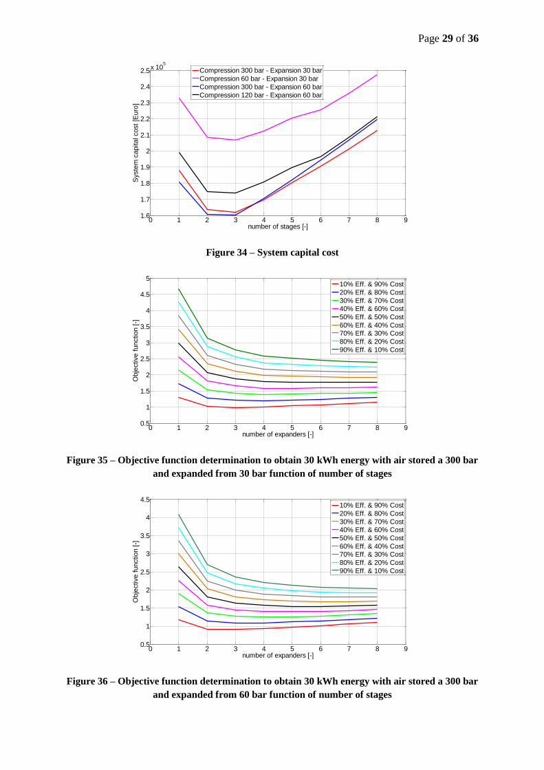
Figure 34 – System capital cost
Figure 35 – Objective function determination to obtain 30 kWh energy with air stored a 300 bar
and expanded from 30 bar function of number of stages
Figure 36 – Objective function determination to obtain 30 kWh energy with air stored a 300 bar
and expanded from 60 bar function of number of stages
0 1 2 3 4 5 6 7 8 91.6
1.7
1.8
1.9
2
2.1
2.2
2.3
2.4
2.5x 10
5
number of stages [-]
Syste
m c
apital cost [E
uro
]
Compression 300 bar - Expansion 30 bar
Compression 60 bar - Expansion 30 bar
Compression 300 bar - Expansion 60 bar
Compression 120 bar - Expansion 60 bar
0 1 2 3 4 5 6 7 8 90.5
1
1.5
2
2.5
3
3.5
4
4.5
5
number of expanders [-]
Obje
ctive function [-]
10% Eff. & 90% Cost
20% Eff. & 80% Cost
30% Eff. & 70% Cost
40% Eff. & 60% Cost
50% Eff. & 50% Cost
60% Eff. & 40% Cost
70% Eff. & 30% Cost
80% Eff. & 20% Cost
90% Eff. & 10% Cost
0 1 2 3 4 5 6 7 8 90.5
1
1.5
2
2.5
3
3.5
4
4.5
number of expanders [-]
Obje
ctive function [-]
10% Eff. & 90% Cost
20% Eff. & 80% Cost
30% Eff. & 70% Cost
40% Eff. & 60% Cost
50% Eff. & 50% Cost
60% Eff. & 40% Cost
70% Eff. & 30% Cost
80% Eff. & 20% Cost
90% Eff. & 10% Cost
Page 30 of 36
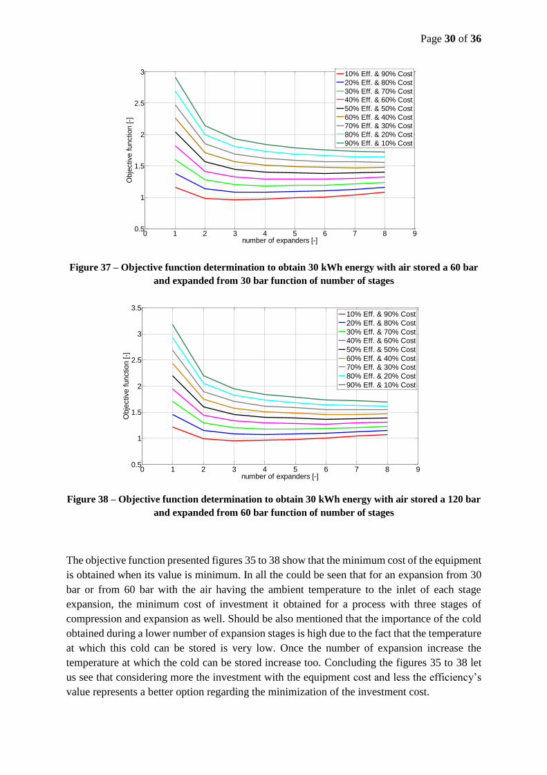
Figure 37 – Objective function determination to obtain 30 kWh energy with air stored a 60 bar
and expanded from 30 bar function of number of stages
Figure 38 – Objective function determination to obtain 30 kWh energy with air stored a 120 bar
and expanded from 60 bar function of number of stages
The objective function presented figures 35 to 38 show that the minimum cost of the equipment
is obtained when its value is minimum. In all the could be seen that for an expansion from 30
bar or from 60 bar with the air having the ambient temperature to the inlet of each stage
expansion, the minimum cost of investment it obtained for a process with three stages of
compression and expansion as well. Should be also mentioned that the importance of the cold
obtained during a lower number of expansion stages is high due to the fact that the temperature
at which this cold can be stored is very low. Once the number of expansion increase the
temperature at which the cold can be stored increase too. Concluding the figures 35 to 38 let
us see that considering more the investment with the equipment cost and less the efficiency’s
value represents a better option regarding the minimization of the investment cost.
0 1 2 3 4 5 6 7 8 90.5
1
1.5
2
2.5
3
number of expanders [-]
Obje
ctive function [-]
10% Eff. & 90% Cost
20% Eff. & 80% Cost
30% Eff. & 70% Cost
40% Eff. & 60% Cost
50% Eff. & 50% Cost
60% Eff. & 40% Cost
70% Eff. & 30% Cost
80% Eff. & 20% Cost
90% Eff. & 10% Cost
0 1 2 3 4 5 6 7 8 90.5
1
1.5
2
2.5
3
3.5
number of expanders [-]
Obje
ctive function [-]
10% Eff. & 90% Cost
20% Eff. & 80% Cost
30% Eff. & 70% Cost
40% Eff. & 60% Cost
50% Eff. & 50% Cost
60% Eff. & 40% Cost
70% Eff. & 30% Cost
80% Eff. & 20% Cost
90% Eff. & 10% Cost
Page 31 of 36
10. Thesis conclusions and perspectives
Energy storage is one of solutions which has the potential to help at the increasing share of
renewable sources into the energy mix, having in the same time a major impact in reducing
greenhouses gas emissions, offering a higher flexibility to the grid, especially in the energy
security of supply.
The main outcomes of the thesis comprehend to different fields of study, one is based on a
thermodynamic analysis and another is focused to find an optimal control for the integration of
renewable energy sources with storage technologies.
Coupling hybrid renewable energy systems, wind and solar energy, with hybrid energy storage
solutions can provide both electricity and heat for consumers use. However is essential that the
system which makes the conversion from one kind of energy into another to be a modular one,
smaller compressors can store more energy than a big compressor due to the required starting
power.
The main limitations that incurred for the use of a CAES system is when is taken in to
consideration the optimizations part. Even if the theoretical results show how the system
efficiency can be improved and which is the direction that has to be followed we face technical
limitations of the compressors, the heat exchangers, the storage vessel, the air engine in terms
of pressure and temperature. The most of the cavern can withstand a certain pressure. Currently
the air engines or turbines operates at pressures of tens of bars so new designs are required in
order to operate at higher pressures and temperatures. .
The complexity of hybrid systems that have the capability of generating several types of energy
makes them desirable especially when the management system will be clearly defined.
Comparing with other storage technologies CAES is not a first time responding technology
like batteries and ultracapacitors and doesn’t have a low discharge time with high power rating,
but it has the huge advantage that there’s no degradation of capacity over time. Once the system
is built it will continue to store the same quantity of energy as long as it exists.
As we already have seen the problem with CAES mostly is not represented by the technical
challenges, it is represented by the storage vessel barriers. Underground caverns tend to be
porous enough but not impermeable enough to allow pressurization, underwater bags could be
a suitable option as long as these don’t involve a high cost.
From economic point of view, definitely at the moment storage energy is expensive indifferent
that we talk about thermal energy storage in the form of hot water, the cheapest ever solution,
or if we talk about electricity storage using any of the existing technologies with all the
advances made in recent years. The current trend to have a much number of intermittent power
sources make to have extra energy that can be wasted, so if the electricity prices are high
enough and this technology has lower cost and if the alternatives are too expensive then storage
energy in the form of compressed air might become more popular.

Page 32 of 36
The results presented show the behavior of the CAES systems and how this evolve over time
trying to find an optimum for energy storage from both technic and economic point of view.
From economic considerations we found that for the moment storage energy in the form of
compressed air is not a viable investment taking into consideration either France or Romanian
context and for sure others due to the fact that the technology cost is a considerable one.
From environmental point of view, it’s interested to observe that such a system which is able
to supply energy in trigeneration could also provide environmental benefits, being a “clean”
source of energy, playing an important role in integrating at a widely scale renewable energy
sources.
As a final it is highlighted the figure 34 where is illustrated the cost needed to build a hybrid
integrated system consisting in equipment to use RES to help in energy storing in a form of
compressed air and then to help to transform the mechanical energy of the air into electricity.
Page 33 of 36
Original contributions
The thesis is among the first studies which connects the energy storage in a form of compressed
air with the renewable energy sources and their intermittent nature.
In the thesis it was developed a theoretical model for the energy storage which refers in
converting the renewable energy in to mechanic energy through compressors, storing it in a
form of compressed air and later used in electricity production.
A weather station it has been installed in a location selected randomly, and where o series of
data in terms of direct solar radiation, wind speed and direction has been collected.
In order to find an optimum for a system which involves the energy storage it’s well known the
fact that there are two optimum possible, one from energy point of view, also called technic
optimum, and another from economic point of view, and the both was analyzed in this thesis.
As expected an energy optimum is hard to find it due to the fact that there are too many factors
which interfere, as the storage vessel pressure ratio, the temperature, the compressor and
expander number of stages, therefore must be found a compromise between the both technic
and economic optimum.
The experimental installation was designed and realized specifically with the objective in
helping in the validation of the theoretical results obtained after mathematical modelling. The
way how the automation part was thought, in terms of parameters monitoring and system
controlling belong to the author.
A theoretical pre-sizing of the storage vessel volume of an energy storage system capable to
supply to the consumer 30kWh depending on the operating parameters, pressure, and
temperature has been realized in this thesis following a Matlab simulation.
Nowadays there are very few studies that deal with energy storage in a form of compressed air
at a small scale. From the best knowledge of the author none of them doesn’t deal with the
economic analysis which proves to be a very important starting point in implementing such
systems
Page 34 of 36
Bibliography
[1] "Forbes," [Online]. Available: http://www.forbes.com/2009/07/24/peak-oil-production-
business-energy-nelder.html. [Accessed 9 April 2015].
[2] S. Lemofouet-Gatsi, "Investigation and optimisation of hybrid electricity storage based on
compressed air and supercapacitors," PhD Thesis - Ecole Polytechnique de Lausanne, 2006.
[3] Zhang Y, Yang K, Li X, Xu J, "The thermodynamic effect of air storage chamber model on
advanced adiabatic compressed air energy storage system," Renewable Energy, no. 57, pp. 469-
478, 2013.
[4] 2009/548/EC, "Commission decision of 30 June 2009 - Establishing a template for national
renewable energy action plans under directive 2009/2/EC of the European Parliament and of the
Council," 2009. [Online]. Available: http://eur-lex.europa.eu.
[5] 2012/27/EC, "Directive 2012/27/EC of the European Parliament and the Council of 25 October
20120on energy efficiency," 2012. [Online].
[6] Evans A, Strezov V, Evans T.J, "Assessment of utility energy storage options for increased
renewable energy penetration," Renewable and Sustainable Energy Reviews, no. 16, pp. 4141-
4147, 2012.
[7] Mahila T.M.I, Saktisahdan T.J, Jannifar A, Hasan M.H, Matseelar H.S.C, "A review of
available methods and development on energy storage - technology update," Renewable and
Sustainable Energy Reviews, no. 33, pp. 532-545, 2014.
[8] "EIA," [Online]. Available:
http://www.eia.gov/todayinenergy/detail.cfm?id=18071#tabs_SpotPriceSlider-2. [Accessed
June 2016].
[9] "System dynamics," [Online]. Available:
http://www.systemdynamics.org/conferences/2013/proceed/papers/P1366.pdf. [Accessed July
2016].
[10] "RTE France," [Online]. Available: http://www.rte-
france.com/sites/default/files/2015_01_27_pk_rte_2014_french_electricity_report.pdf.
[Accessed June 2016].
[11] "Agerpres," [Online]. Available: : http://www.agerpres.ro/economie/2016/01/20/anre-a-
acreditat-pana-la-31-decembrie-2015-capacitati-de-4-662-mw-de-energie-regenerabila-11-50-
41. [Accessed July 2016].
[12] Wang S.Y, Yu J.L, "Optimal sizing of the CAES system in a power system with high wind
power penetration," Electrical Power and Energy Systems, no. 37, pp. 117-125, 2012.
[13] Marano V, Rizzo G, Tiano F.A, "Application of dynamic programming to the optimal
management of a hybrid power plant with wind turbines, photovoltaic panels and compressed
air energy storage," Alllied Energy , no. 97, pp. 849-859.
[14] Bullough C, Gatzen C, Jakiel C, Koller M, Nowi A, Zunft S, "Advanced adiabatic compressed
air energy storage for the integration of wind energy," in EWEC 2004, London, November
2004.
Page 35 of 36
[15] Fiaschi D, Manfrida G, Secchi R, Tempesti , "A versatile system for offshore energy converion
including divesified storage," Energy, no. 48, pp. 566-576, 2012.
[16] Grid Energy Storage U.S Department of Energy, December 2013. [Performance].
[17] Karl Zach, Hans Auer, Hans Lettner, Facilitating energy storage to allow high penetration of
intermittent renewable energy - Report summarizing the current Status,Role and Costs of
Energy Storage Technology, www.store-project.eu, 2012.
[18] Zhang Y, Yang K,Li X, Xu J, "The thermodynamic effect of air storage chamber model on
Advanced Adiabatic Compressed Ari Energy Storage System," Renewable Energy, no. 57, pp.
469-478, 2013.
[19] Kim YM, Shin DG, Favrat D, "Operating characteristics of constant-pressure compressed air
energy storage (CAES) system combined with pumped hydro storage based on energy and
exergy analysis," Energy , no. 36, pp. 6220-6233.
[20] Budny C, Madlener R, Hilgers C, "Economic Feasibility of Pipe Storage and Underground
Reservoir Storage Options for Power-to-Gas Load Balancing," Energy Procedia 61, pp. 2201-
2205, 2014.
[21] Pimm J. A, Garvery D. S, de Jong M, "Design and testing of energy bags for underwater
compressed air energy storage," Energy , no. 66, pp. 496-508, 2014.
[22] Kim YM, Lee JH, Kim SJ, Favrat D, "Potential and evolution of compressed air energy storage:
energy and exergy analyses," Entropy, no. 14, pp. 1501-1521, 2012.
[23] Khushairi M.M, Abdullah H, Hazran H, "A study on the Optimization of Control Strategy of a
Thermal Energy Storage System for Building Air-Conditioning," Procedia Engineering, no. 20,
pp. 118-124, 2011.
[24] Martins M, Villalabos U, Delclos T, Armstrong P, Bergan P, Calvet N, "New concentrating
solar power facility for testing high temperature concrete thermal energy storage," Energy
Procedia 75, pp. 2144-2149, 2015.
[25] Ercan Ataer O, "Storage of thermal energy," [Online]. Available:
http://www.eolss.net/ebooks/sample%20chapters/c08/e3-14-02-00.pdf. [Accessed 20 05 2015].
[26] Hasnain S.M, "Review on sustainable thermal energy storage technologies,part II: cool thermal
storage," Energy Convers Mgmt, no. 39, pp. 1139-1153, 1998.
[27] Ibrahim H, Ilinca A, Perron J., "Energy storage systems - Characteristics and comparison,"
Renewable and Sustainable Reviews , vol. 12, 2008.
[28] Ciocan A, Prisecaru T, Tazerout M, Durastanti J-F, "Thermodynamic evaluation for a small
scale compressed air energy storage system by integrating renewable energy sources," in
ICRERA, Palermo, 2015.
Page 36 of 36
Contributions to energy storage using hybrid systems from alternative energy sources
Contributions to energy storage using hybrid systems from alternative energysources
Résumé
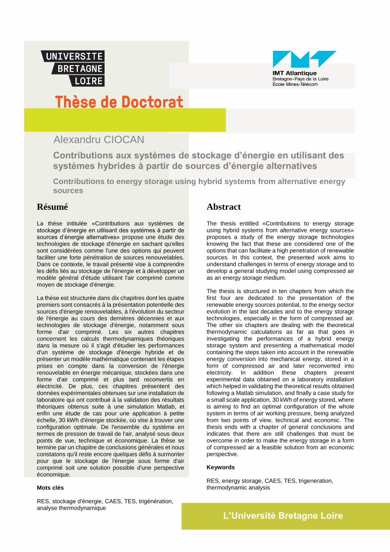
La thèse intitulée «Contributions aux systèmes de stockage d’énergie en utilisant des systèmes à partir de sources d’énergie alternatives» propose une étude des technologies de stockage d'énergie en sachant qu'elles sont considérées comme l'une des options qui peuvent faciliter une forte pénétration de sources renouvelables. Dans ce contexte, le travail présenté vise à comprendre les défis liés au stockage de l'énergie et à développer un modèle général d'étude utilisant l'air comprimé comme moyen de stockage d'énergie.
La thèse est structurée dans dix chapitres dont les quatre premiers sont consacrés à la présentation potentielle des sources d'énergie renouvelables, à l'évolution du secteur de l'énergie au cours des dernières décennies et aux technologies de stockage d'énergie, notamment sous forme d'air comprimé. Les six autres chapitres concernent les calculs thermodynamiques théoriques dans la mesure où il s'agit d'étudier les performances d'un système de stockage d'énergie hybride et de présenter un modèle mathématique contenant les étapes prises en compte dans la conversion de l'énergie renouvelable en énergie mécanique, stockées dans une forme d'air comprimé et plus tard reconvertis en électricité. De plus, ces chapitres présentent des données expérimentales obtenues sur une installation de laboratoire qui ont contribué à la validation des résultats théoriques obtenus suite à une simulation Matlab, et enfin une étude de cas pour une application à petite échelle, 30 kWh d'énergie stockée, où vise à trouver une configuration optimale. De l'ensemble du système en termes de pression de travail de l'air, analysé sous deux points de vue, technique et économique. La thèse se termine par un chapitre de conclusions générales et nous constatons qu'il reste encore quelques défis à surmonter pour que le stockage de l'énergie sous forme d'air comprimé soit une solution possible d'une perspective économique.
Mots clés
RES, stockage d'énergie, CAES, TES, trigénération, analyse thermodynamique
Abstract
The thesis entitled «Contributions to energy storage using hybrid systems from alternative energy sources» proposes a study of the energy storage technologies knowing the fact that these are considered one of the options that can facilitate a high penetration of renewable sources. In this context, the presented work aims to understand challenges in terms of energy storage and to develop a general studying model using compressed air as an energy storage medium.
The thesis is structured in ten chapters from which the first four are dedicated to the presentation of the renewable energy sources potential, to the energy sector evolution in the last decades and to the energy storage technologies, especially in the form of compressed air. The other six chapters are dealing with the theoretical thermodynamic calculations as far as that goes in investigating the performances of a hybrid energy storage system and presenting a mathematical model containing the steps taken into account in the renewable energy conversion into mechanical energy, stored in a form of compressed air and later reconverted into electricity. In addition these chapters present experimental data obtained on a laboratory installation which helped in validating the theoretical results obtained following a Matlab simulation, and finally a case study for a small scale application, 30 kWh of energy stored, where is aiming to find an optimal configuration of the whole system in terms of air working pressure, being analyzed from two points of view, technical and economic. The thesis ends with a chapter of general conclusions and indicates that there are still challenges that must be overcome in order to make the energy storage in a form of compressed air a feasible solution from an economic perspective.
Keywords
RES, energy storage, CAES, TES, trigeneration, thermodynamic analysis
L’Université Bretagne Loire
Contributions aux systèmes de stockage d’énergie en utilisant des systèmes hybrides à partir de sources d’énergie alternatives
Contributions aux systèmes de stockage d’énergie en utilisant dessystèmes hybrides à partir de sources d’énergie alternatives
Alexandru CIOCAN
Alexandru CIOCAN