Embed Size (px)
Citation preview
Guide d'exploitationUser's manualBedienungsanleitungGuía de explotación
Merlin Gerin TelemecaniqueSquare DModicon
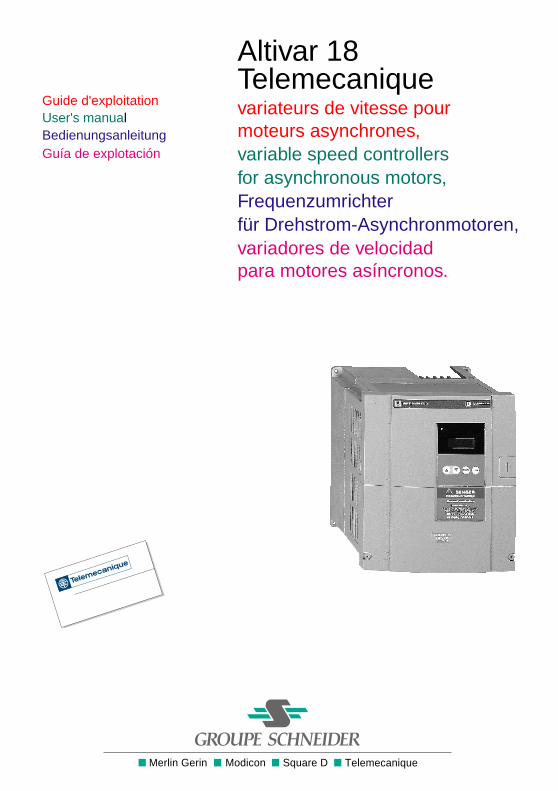
Altivar 18Telemecaniquevariateurs de vitesse pourmoteurs asynchrones,variable speed controllersfor asynchronous motors,Frequenzumrichterfür Drehstrom-Asynchronmotoren,variadores de velocidadpara motores asíncronos.
1
FRANÇAIS
Altivar 18
Variateur de vitesse pour moteurs asynchrones Page 2
Speed controller for asynchronous motors Page 34
Umrichter für Drehstrom-Asynchronmotoren Seite 66
Variador de velocidad para motores asíncronos Página 98
ENGLISH
DEUTSCH
ESPAÑOL
34
ENGLISH
NOTEWARNING
When the speed controller has power on, a number of components are connected to the supply.It is extremely dangerous to touch them.
After switching off the supply to the Altivar wait for 1 minute before touching the equipment. Thisis the time taken for the capacitors to discharge.
During operation the motor can be stopped or started by inhibiting the start command with thespeed controller still connected to the supply. For personnel safety during maintenanceelectronic locking should not be used, the supply should be switched-off.
The speed controller incorporates safety devices which can shutdown the speed controller andstop the motor in the event of a fault. These faults may be caused by a mechanical blockage ofthe motor or alternatively problems with the electrical supply.
The removal of the problem may cause the motor to re-start, creating danger for certain machinesand installations, especially those which must conform to safety regulations.
In such cases, therefore, the user must take precautions to avoid re-starting of the motor. Adevice such as a speed detector should be incorporated to remove the supply in the event of anunscheduled stopping of the motor.
The equipment has been designed to conform to IEC standards.
In general, power to the speed controller must be switched off before any electrical or mechanicalintervention on the installation or machine.
The products and materials presented in this document may be changed or modified at any time,either from a technical point of view or in the way they are operated. Their description can in noway be considered contractual.
35
ENGLISH
This speed controller must be installed and set up in accordance with international and nationalstandards. This compliance is the responsibility of the systems integrator who must respect theEuropean community EMC directive amongst others.
The specifications contained in this document must be applied in order to comply with theessential requirements of the EMC directive.
Warning
The Altivar 18 must be considered a component. It is neither a machine nor a piece of equipmentready for use in accordance with European directives (machinery directive and electromagneticcompatibility directive). It is the responsibility of the user to ensure that his machine meets thesestandards.

36
ENGLISH
37
ENGLISH
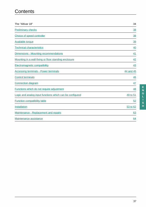
Contents
The "Altivar 18" 34
Preliminary checks 38
Choice of speed controller 38
Available torque 39
Technical characteristics 40
Dimensions - Mounting recommendations 41
Mounting in a wall-fixing or floor standing enclosure 42
Electromagnetic compatibility 43
Accessing terminals - Power terminals 44 and 45
Control terminals 46
Connection diagram 47
Functions which do not require adjustment 48
Logic and analog input functions which can be configured 49 to 51
Function compatibility table 52
Installation 53 to 62
Maintenance - Replacement and repairs 63
Maintenance assistance 64
38
ENGLISH
Preliminary checks
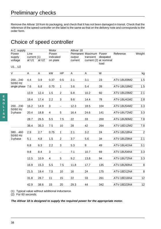
Remove the Altivar 18 from its packaging, and check that it has not been damaged in transit. Check that thereference of the speed controller on the label is the same as that on the delivery note and corresponds to theorder form.
Choice of speed controllerA.C. supply Motor Altivar 18Power Line Power Permanent Maximum Power Reference Weightsupply current (1) indicated output transient dissipatedvoltage at U1 at U2 on plate current current (2) at nominal
loadU1…U2
V A A kW HP A A W kg
200…240 4.4 3.9 0.37 0.5 2.1 3.1 23 ATV-18U09M2 1.550/60 Hzsingle phase 7.6 6.8 0.75 1 3.6 5.4 39 ATV-18U18M2 1.5
13.9 12.4 1.5 2 6.8 10.2 60 ATV-18U29M2 2.1
19.4 17.4 2.2 3 9.6 14.4 78 ATV-18U41M2 2.8
200…230 16.2 14.9 3 – 12.3 18.5 104 ATV-18U54M2 3.350/60 Hz3-phase 20.4 18.8 4 5 16.4 24.6 141 ATV-18U72M2 3.3
28.7 26.5 5.5 7.5 22 33 200 ATV-18U90M2 7.8
38.4 35.3 7.5 10 28 42 264 ATV-18D12M2 7.8
380…460 2.9 2.7 0.75 1 2.1 3.2 24 ATV-18U18N4 250/60 Hz3-phase 5.1 4.8 1.5 2 3.7 5.6 34 ATV-18U29N4 2.1
6.8 6.3 2.2 3 5.3 8 49 ATV-18U41N4 3.1
9.8 8.4 3 – 7.1 10.7 69 ATV-18U54N4 3.3
12.5 10.9 4 5 9.2 13.8 94 ATV-18U72N4 3.3
16.9 15.3 5.5 7.5 11.8 17.7 135 ATV-18U90N4 8
21.5 19.4 7.5 10 16 24 175 ATV-18D12N4 8
31.8 28.7 11 15 22 33 261 ATV-18D16N4 12
42.9 38.6 15 20 29.3 44 342 ATV-18D23N4 12
(1) Typical value without additional inductance.(2) For 60 seconds.
The Altivar 18 is designed to supply the required power for the appropriate motor.
39
ENGLISH
Available torque
Continuous operation
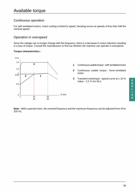
For self-ventilated motors, motor cooling is linked to speed. Derating occurs at speeds of less than half thenominal speed.
Operation in overspeed
Since the voltage can no longer change with the frequency, there is a decrease in motor induction resultingin a loss of torque. Consult the manufacturer to find out whether the machine can operate in overspeed.
Torque characteristics :
1 Continuous usable torque : self-ventilated motor
2 Continuous usable torque : force-ventilatedmotor
3 Transient overtorque : typical curve at ± 10 %Value : 1.5 Tn for 60 s
Note : With a special motor, the nominal frequency and the maximum frequency can be adjusted from 40 to320 Hz.
0 N (Hz)
0,5
2530
5060
1
3
2 11
0,95
1,5
T/Tn
1,2
40
ENGLISH
Technical characteristics
Environment
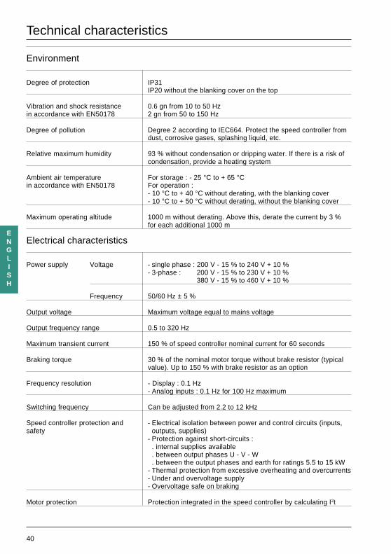
Degree of protection IP31IP20 without the blanking cover on the top
Vibration and shock resistance 0.6 gn from 10 to 50 Hzin accordance with EN50178 2 gn from 50 to 150 Hz
Degree of pollution Degree 2 according to IEC664. Protect the speed controller fromdust, corrosive gases, splashing liquid, etc.
Relative maximum humidity 93 % without condensation or dripping water. If there is a risk ofcondensation, provide a heating system
Ambient air temperature For storage : - 25 °C to + 65 °Cin accordance with EN50178 For operation :
- 10 °C to + 40 °C without derating, with the blanking cover- 10 °C to + 50 °C without derating, without the blanking cover
Maximum operating altitude 1000 m without derating. Above this, derate the current by 3 %for each additional 1000 m
Electrical characteristics
Power supply Voltage - single phase : 200 V - 15 % to 240 V + 10 %- 3-phase : 200 V - 15 % to 230 V + 10 %
380 V - 15 % to 460 V + 10 %
Frequency 50/60 Hz ± 5 %
Output voltage Maximum voltage equal to mains voltage
Output frequency range 0.5 to 320 Hz
Maximum transient current 150 % of speed controller nominal current for 60 seconds
Braking torque 30 % of the nominal motor torque without brake resistor (typicalvalue). Up to 150 % with brake resistor as an option
Frequency resolution - Display : 0.1 Hz- Analog inputs : 0.1 Hz for 100 Hz maximum
Switching frequency Can be adjusted from 2.2 to 12 kHz
Speed controller protection and - Electrical isolation between power and control circuits (inputs,safety outputs, supplies)
- Protection against short-circuits :. internal supplies available. between output phases U - V - W. between the output phases and earth for ratings 5.5 to 15 kW
- Thermal protection from excessive overheating and overcurrents- Under and overvoltage supply- Overvoltage safe on braking
Motor protection Protection integrated in the speed controller by calculating I2t
41
ENGLISH
Dimensions - Mounting recommendations
Dimensions
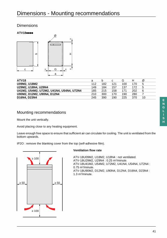
ATV18iiii
ATV18 a b c G H ØU09M2, U18M2 112 182 121 100 170 5U29M2, U18N4, U29N4 149 184 157 137 172 5U41M2, U54M2, U72M2, U41N4, U54N4, U72N4 185 215 158 171 202 6U90M2, D12M2, U90N4, D12N4 210 300 170 190 280 7D16N4, D23N4 245 390 190 225 370 10
Mounting recommendations
Mount the unit vertically.
Avoid placing close to any heating equipment.
Leave enough free space to ensure that sufficient air can circulate for cooling. The unit is ventilated from thebottom upwards.
IP2O : remove the blanking cover from the top (self-adhesive film).
Ventilation flow rate
ATV-18U09M2, U18M2, U18N4 : not ventilated.ATV-18U29M2, U29N4 : 0.25 m3/minute.ATV-18U41M2, U54M2, U72M2, U41N4, U54N4, U72N4 :0.75 m3/minute.ATV-18U90M2, D12M2, U90N4, D12N4, D16N4, D23N4 :1.3 m3/minute.
c
b
a
G
Ø
= =H
==
≥ 50 ≥ 50
≥ 100
≥ 100
42
ENGLISH
Mounting in a wall-fixing or floor-standing enclosure
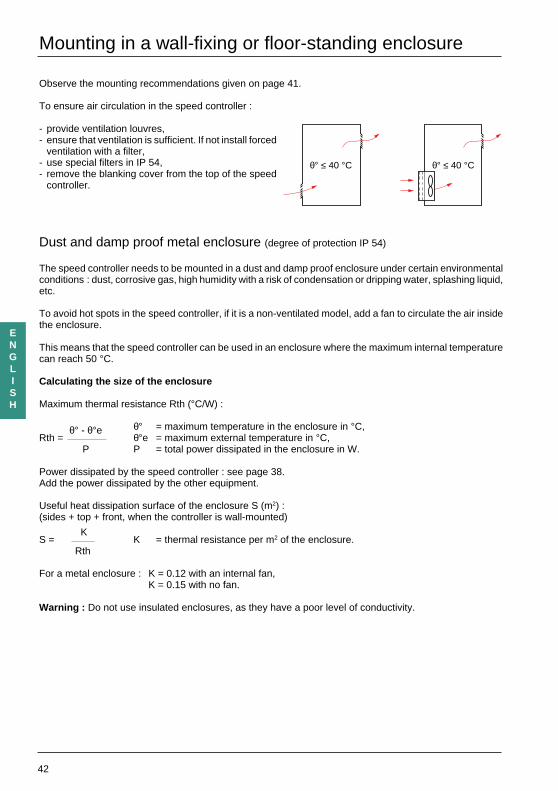
Observe the mounting recommendations given on page 41.
To ensure air circulation in the speed controller :
- provide ventilation louvres,- ensure that ventilation is sufficient. If not install forced
ventilation with a filter,- use special filters in IP 54,- remove the blanking cover from the top of the speed
controller.
Dust and damp proof metal enclosure (degree of protection IP 54)
The speed controller needs to be mounted in a dust and damp proof enclosure under certain environmentalconditions : dust, corrosive gas, high humidity with a risk of condensation or dripping water, splashing liquid,etc.
To avoid hot spots in the speed controller, if it is a non-ventilated model, add a fan to circulate the air insidethe enclosure.
This means that the speed controller can be used in an enclosure where the maximum internal temperaturecan reach 50 °C.
Calculating the size of the enclosure
Maximum thermal resistance Rth (°C/W) :
θ° = maximum temperature in the enclosure in °C,Rth =
θ° - θ°eθ°e = maximum external temperature in °C,
P P = total power dissipated in the enclosure in W.
Power dissipated by the speed controller : see page 38.Add the power dissipated by the other equipment.
Useful heat dissipation surface of the enclosure S (m2) :(sides + top + front, when the controller is wall-mounted)
S =K
K = thermal resistance per m2 of the enclosure.Rth
For a metal enclosure : K = 0.12 with an internal fan,K = 0.15 with no fan.
Warning : Do not use insulated enclosures, as they have a poor level of conductivity.
θ° ≤ 40 °C θ° ≤ 40 °C
43
ENGLISH
Electromagnetic compatibility
Installation : to comply with standards EN55011 class A, EN61800-3, IEC1800-3.
General rules
- Grounds between speed controller, motor and cable shielding must have "high frequency" equipotentiality.
- Use shielded cables with shielding connected to the ground at 360° at both ends of the motor cable andthe control cables. This shielding can be conduit or metal ducting as long as there is no break in continuity.
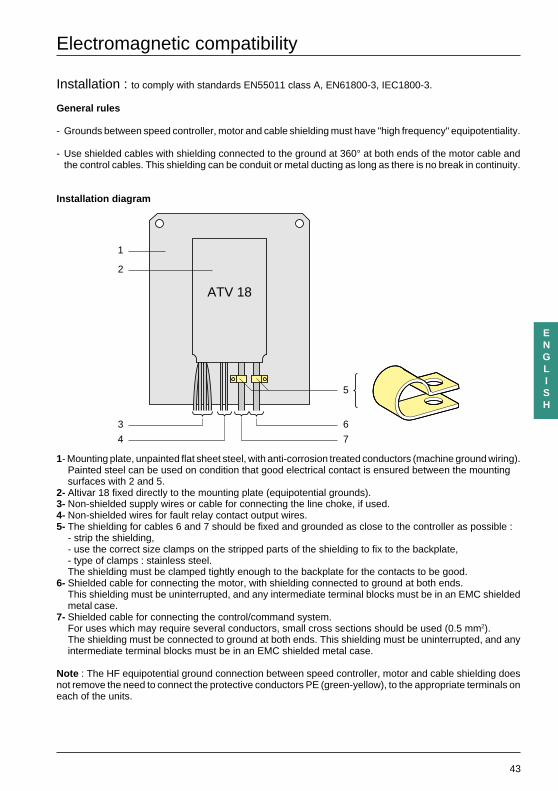
Installation diagram
1- Mounting plate, unpainted flat sheet steel, with anti-corrosion treated conductors (machine ground wiring).Painted steel can be used on condition that good electrical contact is ensured between the mountingsurfaces with 2 and 5.
2- Altivar 18 fixed directly to the mounting plate (equipotential grounds).3- Non-shielded supply wires or cable for connecting the line choke, if used.4- Non-shielded wires for fault relay contact output wires.5- The shielding for cables 6 and 7 should be fixed and grounded as close to the controller as possible :
- strip the shielding,- use the correct size clamps on the stripped parts of the shielding to fix to the backplate,- type of clamps : stainless steel.The shielding must be clamped tightly enough to the backplate for the contacts to be good.
6- Shielded cable for connecting the motor, with shielding connected to ground at both ends.This shielding must be uninterrupted, and any intermediate terminal blocks must be in an EMC shieldedmetal case.
7- Shielded cable for connecting the control/command system.For uses which may require several conductors, small cross sections should be used (0.5 mm2).The shielding must be connected to ground at both ends. This shielding must be uninterrupted, and anyintermediate terminal blocks must be in an EMC shielded metal case.
Note : The HF equipotential ground connection between speed controller, motor and cable shielding doesnot remove the need to connect the protective conductors PE (green-yellow), to the appropriate terminals oneach of the units.
ATV 18
1
2
3
4
6
7
5
44
ENGLISH
Accessing terminals - Power terminals
Accessing terminal blocks
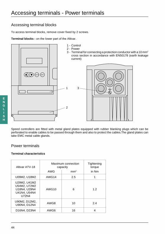
To access terminal blocks, remove cover fixed by 2 screws.
Terminal blocks : on the lower part of the Altivar.
1 - Control2 - Power3 - Terminal for connecting a protection conductor with a 10 mm2
cross section in accordance with EN50178 (earth leakagecurrent)
Speed controllers are fitted with metal gland plates equipped with rubber blanking plugs which can beperforated to enable cables to be passed through them and also to protect the cables.The gland plates cantake EMC metal cable glands.
Power terminals
Terminal characteristics
Maximum connection TighteningAltivar ATV-18 capacity torque
AWG mm2 in Nm
U09M2, U18M2 AWG14 2.5 1
U29M2, U41M2U54M2, U72M2U18N4, U29N4 AWG10 6 1.2U41N4, U54N4
U72N4
U90M2, D12M2,U90N4, D12N4 AWG8 10 2.4
D16N4, D23N4 AWG6 16 4
DATA ENT
1 3
2
45
ENGLISH
Power terminals
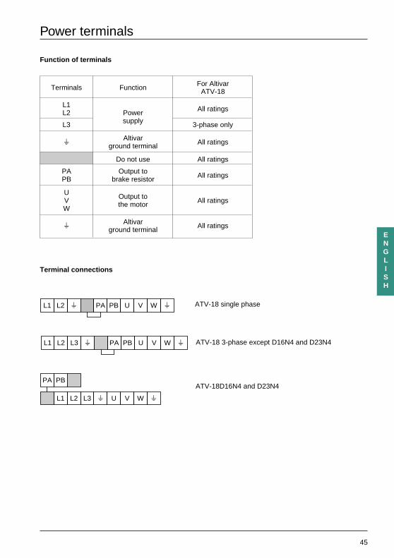
Function of terminals
Terminals Function For AltivarATV-18
L1L2 Power All ratings
L3 supply 3-phase only
s Altivar All ratingsground terminal
Do not use All ratings
PA Output to All ratingsPB brake resistor
U Output toV All ratingsW the motor
s Altivar All ratingsground terminal
Terminal connections
L1 L2 L3
PA PB
s PA PB U V
L1 L2 L3 s U V W s
W s
L1 L2 s PA PB U V W s ATV-18 single phase
ATV-18 3-phase except D16N4 and D23N4
ATV-18D16N4 and D23N4
46
ENGLISH
Control terminals
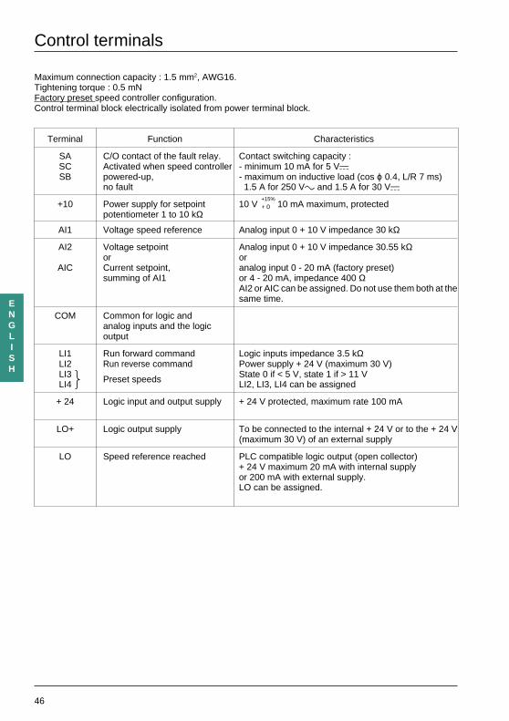
Maximum connection capacity : 1.5 mm2, AWG16.Tightening torque : 0.5 mNFactory preset speed controller configuration.Control terminal block electrically isolated from power terminal block.
Terminal Function Characteristics
SA C/O contact of the fault relay. Contact switching capacity :SC Activated when speed controller - minimum 10 mA for 5 VaSB powered-up, - maximum on inductive load (cos ϕ 0.4, L/R 7 ms)
no fault 1.5 A for 250 Vc and 1.5 A for 30 Va
+10 Power supply for setpoint 10 V+15%
10 mA maximum, protectedpotentiometer 1 to 10 kΩ
+ 0
AI1 Voltage speed reference Analog input 0 + 10 V impedance 30 kΩ
AI2 Voltage setpoint Analog input 0 + 10 V impedance 30.55 kΩor or
AIC Current setpoint, analog input 0 - 20 mA (factory preset)summing of AI1 or 4 - 20 mA, impedance 400 Ω
AI2 or AIC can be assigned. Do not use them both at thesame time.
COM Common for logic andanalog inputs and the logicoutput
LI1 Run forward command Logic inputs impedance 3.5 kΩLI2 Run reverse command Power supply + 24 V (maximum 30 V)LI3 Preset speeds State 0 if < 5 V, state 1 if > 11 VLI4 LI2, LI3, LI4 can be assigned
+ 24 Logic input and output supply + 24 V protected, maximum rate 100 mA
LO+ Logic output supply To be connected to the internal + 24 V or to the + 24 V(maximum 30 V) of an external supply
LO Speed reference reached PLC compatible logic output (open collector)+ 24 V maximum 20 mA with internal supplyor 200 mA with external supply.LO can be assigned.
47
ENGLISH
U V W PA
PB
+10
AI1
CO
M
AIC
PO
L1U
1
W1
V1
M 3 c
L2 L3 SB
SC
SA
LI1
LI2
LI3
LI4
+24
AI2
LO LO+
KA(3)
(4)
CO
M
LI1
LI2
LI3
LI4
+24
0 V
+24
VLO
+
(4)
(2)
(1)
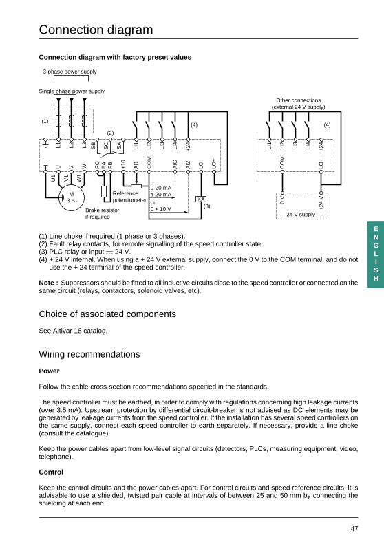
Connection diagram
Connection diagram with factory preset values
(1) Line choke if required (1 phase or 3 phases).(2) Fault relay contacts, for remote signalling of the speed controller state.(3) PLC relay or input a 24 V.(4) + 24 V internal. When using a + 24 V external supply, connect the 0 V to the COM terminal, and do not
use the + 24 terminal of the speed controller.
Note : Suppressors should be fitted to all inductive circuits close to the speed controller or connected on thesame circuit (relays, contactors, solenoid valves, etc).
Choice of associated components
See Altivar 18 catalog.
Wiring recommendations
Power
Follow the cable cross-section recommendations specified in the standards.
The speed controller must be earthed, in order to comply with regulations concerning high leakage currents(over 3.5 mA). Upstream protection by differential circuit-breaker is not advised as DC elements may begenerated by leakage currents from the speed controller. If the installation has several speed controllers onthe same supply, connect each speed controller to earth separately. If necessary, provide a line choke(consult the catalogue).
Keep the power cables apart from low-level signal circuits (detectors, PLCs, measuring equipment, video,telephone).
Control
Keep the control circuits and the power cables apart. For control circuits and speed reference circuits, it isadvisable to use a shielded, twisted pair cable at intervals of between 25 and 50 mm by connecting theshielding at each end.
Single phase power supply
3-phase power supply
Referencepotentiometer
Brake resistorif required 24 V supply
0-20 mA4-20 mA
or0 + 10 V
Other connections(external 24 V supply)
48
ENGLISH
Functions which do not require adjustment
Fault relay, resetting
The fault relay is energized when the speed controller is powered up and not faulty. It comprises a C/O contact.
The speed controller is reset after a fault :
- by switching it off until the display and the red indicator lamp disappear and then restarting the speedcontroller,
- automatically in the cases described under the "automatic restart" function.
Thermal protection of the speed controller
Function :
Protection via a thermistor fixed to the heatsink.
Indirect protection of the speed controller by calculating the I2t.
This function ensures thermal protection of the speed controller in normal ambient temperature conditions.
Typical tripping points :
- motor current = 185 % of the nominal speed controller current : 2 seconds,- motor current = 150 % of the nominal speed controller current : 60 seconds,- motor current ≤ 110 % of the nominal speed controller current : does not trip.
Possible deratings for switching frequencies of > 4 kHz are automatically taken into account and reduce theadmissible I2t.
Warning : If the speed controller is switched off, the I2t calculation is reset to 0.
Speed controller ventilation
For models which have a fan, the fan is supplied automatically when the speed controller is reset (operatingdirection + reference). It is switched off several seconds after the speed controller is locked (motor speed< 0.5 Hz and injection braking completed).
49
ENGLISH
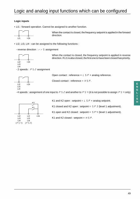
Logic and analog input functions which can be configured
Logic inputs
• LI1 : forward operation. Cannot be assigned to another function.
When the contact is closed, the frequency setpoint is applied in the forwarddirection.
• LI2, LI3, LI4 : can be assigned to the following functions :
- reverse direction : rrS assignment
When the contact is closed, the frequency setpoint is applied in reversedirection. If LI1 is also closed, the first one to have been closed has priority.
- 2 speeds : PS2 assignment
Open contact : reference = LSP + analog reference.
Closed contact : reference = HSP.
- 4 speeds : assignment of one input to PS2 and another to PS4 (it is not possible to assign PS4 only)
K1 and K2 open : setpoint = L5P + analog setpoint.
K1 closed and K2 open : setpoint = SP3 (level 1 adjustment).
K1 open and K2 closed : setpoint = SP4 (level 1 adjustment).
K1 and K2 closed : setpoint = HSP.
LI1 +24
LI2LI3LI4
+24
LI2LI3LI4
+24
LI2LI3LI4
(PS2)
LI2LI3LI4
(PS4)
K2
K1
+24
50
ENGLISH
Logic and analog input functions which can be configured
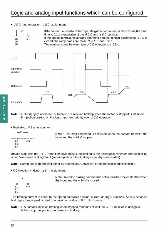
• JOG : jog operation. JOG assignment
If the contact is closed and then operating direction contact is also closed, the ramptime is 0.1 s irrespective of the ACC and dEC settings.If the speed controller is already operating and the contact assigned to JOG isclosed, the ramp times are those of ACC and dEC.The minimum time between two JOG operations is 0.5 s.
Note : 1- During "jog" operation, automatic DC injection braking when the motor is stopped is inhibited.2- Injection braking on the logic input has priority over JOG operation.
• Fast stop : FSt assignment
Note : Fast stop command is activated when the contact between theinput and the + 24 V is open.
Braked stop, with the dEC ramp time divided by 4, but limited to the acceptable minimum without lockingon an "excessive braking" fault (self-adaptation if the braking capability is exceeded).
Note : During fast stop, braking either by automatic DC injection or on the logic input is inhibited.
• DC injection braking : dCI assignment
Note : Injection braking command is activated when the contact betweenthe input and the + 24 V is closed.
The braking current is equal to the speed controller nominal current during 5 seconds. After 5 seconds,braking current is peak limited to a maximum value of 0.5 ItH motor.
Note : 1- Automatic injection braking when stopped remains active if the dCI function is assigned.2- Fast stop has priority over injection braking.
LI2LI3LI4
+24
Operatingdirection
Reference
JOG
JOG JOG JOG
Frequency
Ref.
Ref.
LI2LI3LI4
+24
LI2LI3LI4
+24
51
ENGLISH
Logic and analog input functions which can be configured
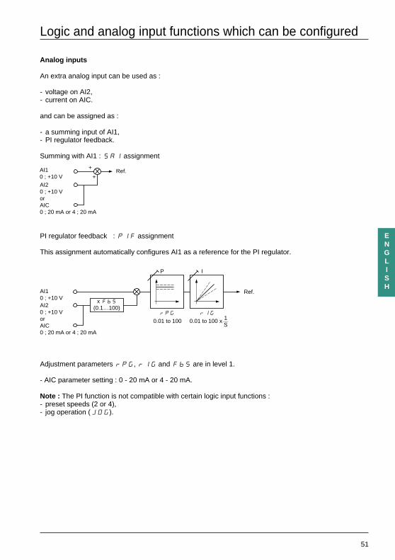
Analog inputs
An extra analog input can be used as :
- voltage on AI2,- current on AIC.
and can be assigned as :
- a summing input of AI1,- PI regulator feedback.
Summing with AI1 : SAI assignment
PI regulator feedback : PIF assignment
This assignment automatically configures AI1 as a reference for the PI regulator.
Adjustment parameters rPG, rIG and FbS are in level 1.
- AIC parameter setting : 0 - 20 mA or 4 - 20 mA.
Note : The PI function is not compatible with certain logic input functions :- preset speeds (2 or 4),- jog operation (JOG).
AI10 ; +10 V
+
+AI20 ; +10 VorAIC0 ; 20 mA or 4 ; 20 mA
Ref.
x Fb5(0.1…100)
rPG
P
rIG
I
0.01 to 100 x 1S
0.01 to 100
Ref.AI10 ; +10 VAI20 ; +10 VorAIC0 ; 20 mA or 4 ; 20 mA
52
ENGLISH
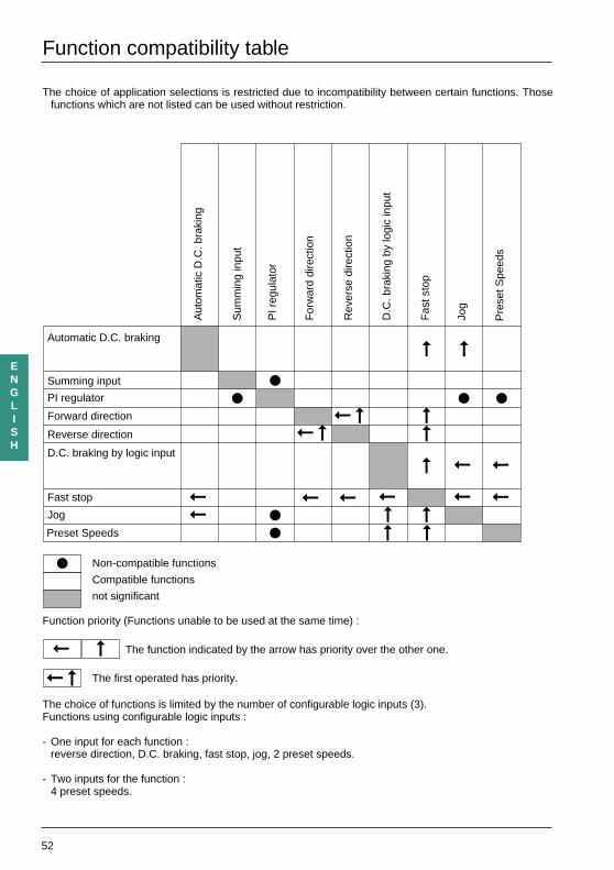
Function compatibility table
The choice of application selections is restricted due to incompatibility between certain functions. Thosefunctions which are not listed can be used without restriction.
Non-compatible functions
Compatible functions
not significant
Function priority (Functions unable to be used at the same time) :
The function indicated by the arrow has priority over the other one.
The first operated has priority.
The choice of functions is limited by the number of configurable logic inputs (3).Functions using configurable logic inputs :
- One input for each function :reverse direction, D.C. braking, fast stop, jog, 2 preset speeds.
- Two inputs for the function :4 preset speeds.
Summing input
PI regulator
Forward direction
Reverse direction
Fast stop
Jog
Preset Speeds
Automatic D.C. braking
Pre
set S
peed
s
Jog
Fas
t sto
p
Rev
erse
dire
ctio
n
For
war
d di
rect
ion
PI r
egul
ator
Sum
min
g in
put
D.C
. bra
king
by
logi
c in
put
Aut
omat
ic D
.C. b
raki
ng
D.C. braking by logic input
53
ENGLISH
Installation
The Altivar is factory preset for standard applications :
- applications with constant torque.
Preset values
- Display : speed controller ready (when stopped), motor frequency (in operation).- Supply : 50 Hz.- Motor voltage : 230 V or 400 V, depending on the product.- Ramps : 3 seconds.- Low speed : 0 Hz - High speed : 50 Hz.- Frequency loop gain : standard.- Thermal motor current = nominal speed controller current.- Injection braking current when stopped = 0.7 nominal speed controller current, for 0.5 seconds.- Operation at constant torque, with sensorless flux vector control.- Logic inputs :
. 2 operating directions (LI1, LI2),
. 4 preset speeds (LI3, LI4) : 0 Hz, 5 Hz, 25 Hz, 50 Hz.- Analog inputs :
. AI1 : speed reference 0 + 10 V,
. AI2 (0 + 10 V) or AIC (0, 20 mA) summing of AI1.- Logic output :
. LO : speed reference reached.- Automatic adaptation of the deceleration ramp if there is overvoltage on braking.- Switching frequency of 4 kHz.
If the above values are compatible with the application, the speed controller can be used without modifyingthe settings.
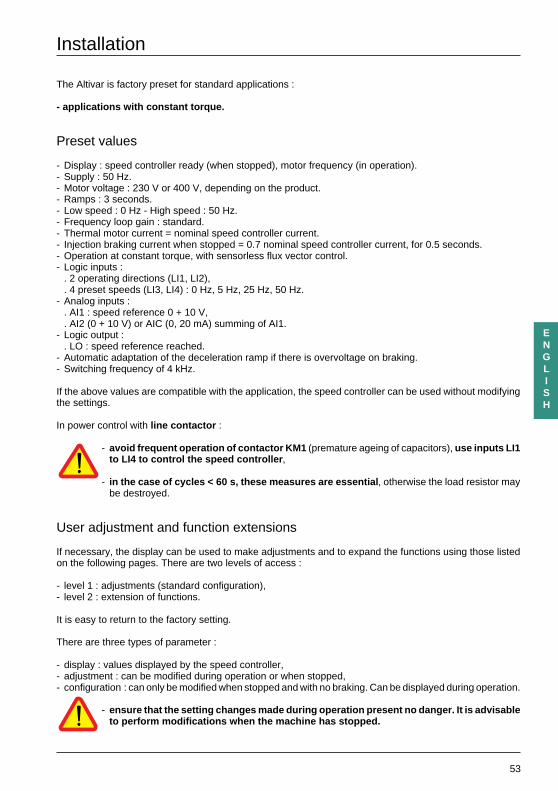
In power control with line contactor :
- avoid frequent operation of contactor KM1 (premature ageing of capacitors), use inputs LI1to LI4 to control the speed controller ,
- in the case of cycles < 60 s, these measures are essential , otherwise the load resistor maybe destroyed.
User adjustment and function extensions
If necessary, the display can be used to make adjustments and to expand the functions using those listedon the following pages. There are two levels of access :
- level 1 : adjustments (standard configuration),- level 2 : extension of functions.
It is easy to return to the factory setting.
There are three types of parameter :
- display : values displayed by the speed controller,- adjustment : can be modified during operation or when stopped,- configuration : can only be modified when stopped and with no braking. Can be displayed during operation.
- ensure that the setting changes made during operation present no danger. It is advisableto perform modifications when the machine has stopped.
54
ENGLISH
Installation
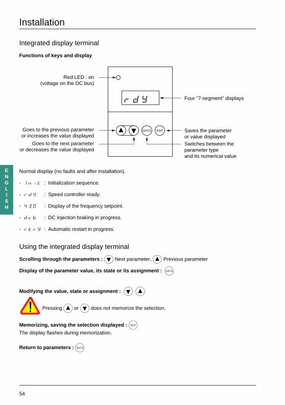
Integrated display terminal
Functions of keys and display
Normal display (no faults and after installation).
- Init : Initialization sequence.
- rdY : Speed controller ready.
- 4“0 : Display of the frequency setpoint.
- dcb : DC injection braking in progress.
- rtrY : Automatic restart in progress.
Using the integrated display terminal
Scrolling through the parameters : Next parameter, Previous parameter
Display of the parameter value, its state or its assignment : DATA
Modifying the value, state or assignment :
Pressing or does not memorize the selection.
Memorizing, saving the selection displayed : ENT
The display flashes during memorization.
Return to parameters : DATA
DATA ENT
rdY
Red LED : on(voltage on the DC bus)
Four "7-segment" displays
Saves the parameteror value displayedSwitches between the parameter typeand its numerical value
Goes to the previous parameteror increases the value displayed
Goes to the next parameteror decreases the value displayed
55
ENGLISH
Installation
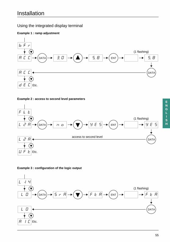
Using the integrated display terminal
Example 1 : ramp adjustment
Example 2 : access to second level parameters
Example 3 : configuration of the logic output
bFr
ACC “0
ACC
8 8
dEC
DATA ENT
DATA
(1 flashing)
Etc.
(1 flashing)
Etc.
FLt
L2A no
L2A
YES YES
UFt
DATA ENT
DATA
(1 flashing)
Etc.
LI4
LO SrA
LO
FtA FtA
AIC
DATA ENT
DATA
access to second level
56
ENGLISH
rdYrdY 4545
FrHFrH
LCrLCr
CPUCPU
rFrrFr
ULnULn
ACC
dEC
LSP
HSP
FLG
ItH
JPF
IdC
tdC
UFr
bFr
UFt
tUn
UnS
FrS
tFr
SLP
LI2
tLS
LI3
LI4
Atr
FCS
LO
AIC
CrL
SPr
SFr
StP
brA
FLtFLt
L2A
L2A = YESL2A
= no
L2A = YES
SP3
SP4
JOG
Fdt
rPG
rIG
FbS
*
*******
*
*
Installation
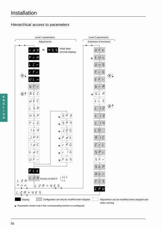
Hierarchical access to parameters
Level 1 parameters
Adjustments
or Initial state(normal display)
Level 2 parameters
Extension of functions
Access to level 2
Display Configuration can only be modified when stopped Adjustment can be modified when stopped andwhen running
Parameter shown only if the corresponding function is configured
YES
no
57
ENGLISH
Installation
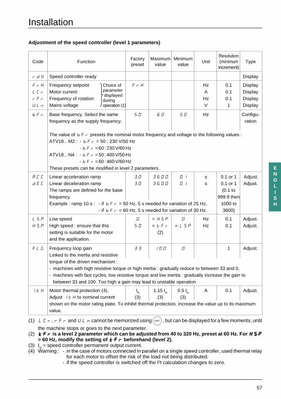
Adjustment of the speed controller (level 1 parameters)
Factory Maximum MinimumResolution
Code Functionpreset value value
Unit (minimum Typeincrement)
rdY Speed controller ready Display
FrH Frequency setpoint FrH Hz 0.1 DisplayLCr Motor current A 0.1 DisplayrFr Frequency of rotation Hz 0.1 DisplayULn Mains voltage V 1 Display
bFr Base frequency. Select the same 50 60 50 Hz Configu-frequency as the supply frequency. ration
The value of bFr presets the nominal motor frequency and voltage to the following values :ATV18…M2 : - bFr = 50 : 230 V/50 Hz
- bFr = 60 : 230 V/60 HzATV18…N4 : - bFr = 50 : 400 V/50 Hz
- bFr = 60 : 460 V/60 HzThese presets can be modified in level 2 parameters.
ACC Linear acceleration ramp “0 3600 ø1 s 0.1 or 1 Adjust.dEC Linear deceleration ramp “0 3600 ø1 s 0.1 or 1 Adjust.
The ramps are defined for the base (0.1 tofrequency. 999.9 thenExample : ramp 10 s : - if bFr = 50 Hz, 5 s needed for variation of 25 Hz, 1000 to
- if bFr = 60 Hz, 5 s needed for variation of 30 Hz. 3600)
LSP Low speed 0 = HSP 0 Hz 0.1 Adjust.HSP High speed : ensure that this 50 = tFr = LSP Hz 0.1 Adjust.
setting is suitable for the motor (2)and the application.
FLG Frequency loop gain 33 100 0 1 Adjust.Linked to the inertia and resistivetorque of the driven mechanism :- machines with high resistive torque or high inertia : gradually reduce to between 33 and 0,- machines with fast cycles, low resistive torque and low inertia : gradually increase the gain to
between 33 and 100. Too high a gain may lead to unstable operation
ItH Motor thermal protection (4). IN 1.15 IN 0.5 IN A 0.1 Adjust.Adjust ItH to nominal current (3) (3) (3)shown on the motor rating plate. To inhibit thermal protection, increase the value up to its maximumvalue.
(1) LCr, rFr and ULn cannot be memorized using ENT , but can be displayed for a few moments, until
the machine stops or goes to the next parameter.(2) tFrtFrtFrtFrtFr is a level 2 parameter which can be adjusted from 40 to 320 Hz, preset at 60 Hz. For HSPHSPHSPHSPHSP
> 60 Hz, modify the setting of tFrtFrtFrtFrtFr beforehand (level 2).(3) IN = speed controller permanent output current.(4) Warning : - in the case of motors connected in parallel on a single speed controller, used thermal relay
for each motor to offset the risk of the load not being distributed.- if the speed controller is switched off the I2t calculation changes to zero.
Choice ofparameter displayedduringoperation (1)
58
ENGLISH
Installation
Adjustment of speed controller (level 1 parameters)
Factory Maximum MinimumResolution
Code Functionpreset value value
Unit (minimum Typeincrement)
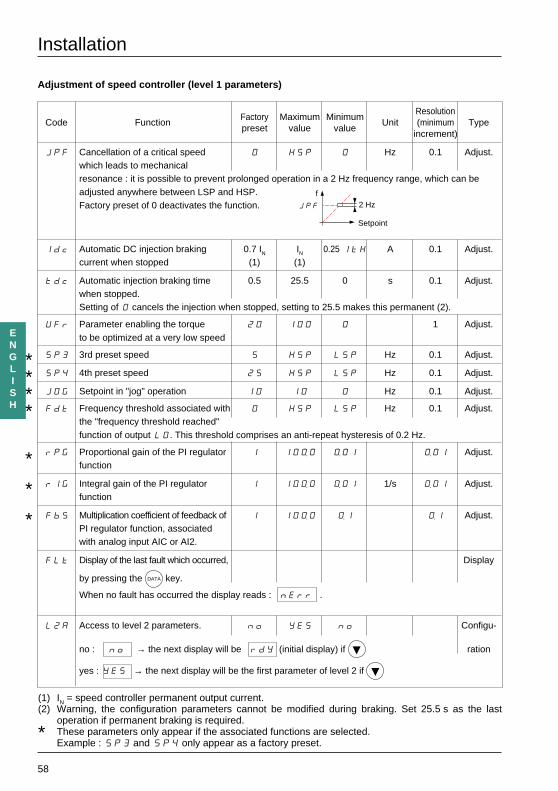
JPF Cancellation of a critical speed 0 HSP 0 Hz 0.1 Adjust.which leads to mechanicalresonance : it is possible to prevent prolonged operation in a 2 Hz frequency range, which can beadjusted anywhere between LSP and HSP.Factory preset of 0 deactivates the function.
Idc Automatic DC injection braking 0.7 IN IN 0.25 ItH A 0.1 Adjust.current when stopped (1) (1)
tdc Automatic injection braking time 0.5 25.5 0 s 0.1 Adjust.when stopped.Setting of 0 cancels the injection when stopped, setting to 25.5 makes this permanent (2).
UFr Parameter enabling the torque 20 100 0 1 Adjust.to be optimized at a very low speed
SP3 3rd preset speed S HSP LSP Hz 0.1 Adjust.
SP4 4th preset speed 25 HSP LSP Hz 0.1 Adjust.
JOG Setpoint in "jog" operation 10 10 0 Hz 0.1 Adjust.
Fdt Frequency threshold associated with 0 HSP LSP Hz 0.1 Adjust.the "frequency threshold reached"function of output LO. This threshold comprises an anti-repeat hysteresis of 0.2 Hz.
rPG Proportional gain of the PI regulator 1 10ø0 ø01 ø01 Adjust.function
rIG Integral gain of the PI regulator 1 10ø0 ø01 1/s ø01 Adjust.function
FbS Multiplication coefficient of feedback of 1 10ø0 ø1 ø1 Adjust.PI regulator function, associatedwith analog input AIC or AI2.
FLt Display of the last fault which occurred, Display
by pressing the DATA key.
When no fault has occurred the display reads : nErr .
L2A Access to level 2 parameters. no YES no Configu-
no : no → the next display will be rdY (initial display) if ration
yes : YES → the next display will be the first parameter of level 2 if
JPF 2 Hzf
Setpoint
(1) IN = speed controller permanent output current.(2) Warning, the configuration parameters cannot be modified during braking. Set 25.5 s as the last
operation if permanent braking is required.
* These parameters only appear if the associated functions are selected.Example : SP3 and SP4 only appear as a factory preset.
****
*
*
*
59
ENGLISH
Installation
Extension of functions (level 2 parameters)
Factory Maximum Minimum Resolution
Code Functionpreset value value
Unit (minimum Type increment)
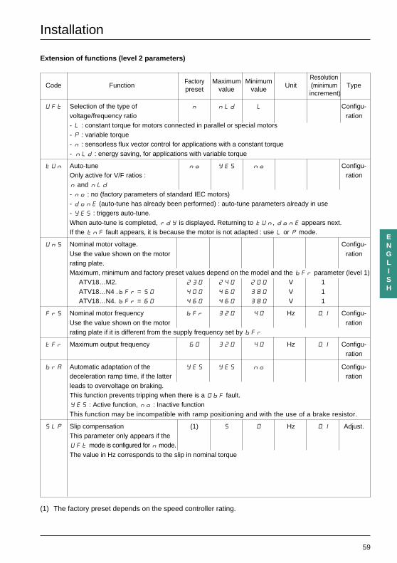
UFt Selection of the type of n nLd L Configu-voltage/frequency ratio ration- L : constant torque for motors connected in parallel or special motors- P : variable torque- n : sensorless flux vector control for applications with a constant torque- nLd : energy saving, for applications with variable torque
tUn Auto-tune no YES no Configu-Only active for V/F ratios : rationn and nLd- no : no (factory parameters of standard IEC motors)- donE (auto-tune has already been performed) : auto-tune parameters already in use- YES : triggers auto-tune.When auto-tune is completed, rdY is displayed. Returning to tUn, donE appears next.If the tnF fault appears, it is because the motor is not adapted : use L or P mode.
UnS Nominal motor voltage. Configu-Use the value shown on the motor rationrating plate.Maximum, minimum and factory preset values depend on the model and the bFr parameter (level 1)
ATV18…M2. 230 240 200 V 1ATV18…N4 .bFr = 50 400 460 380 V 1ATV18…N4. bFr = 60 460 460 380 V 1
FrS Nominal motor frequency bFr 320 40 Hz ø1 Configu-Use the value shown on the motor rationrating plate if it is different from the supply frequency set by bFr
tFr Maximum output frequency 60 320 40 Hz ø1 Configu-ration
brA Automatic adaptation of the YES YES no Configu-deceleration ramp time, if the latter rationleads to overvoltage on braking.This function prevents tripping when there is a ObF fault.YES : Active function, no : Inactive functionThis function may be incompatible with ramp positioning and with the use of a brake resistor.
SLP Slip compensation (1) 5 0 Hz ø1 Adjust.This parameter only appears if theUFt mode is configured for n mode.The value in Hz corresponds to the slip in nominal torque
(1) The factory preset depends on the speed controller rating.
60
ENGLISH
Installation
Extension of functions (level 2 parameters)
Factory Maximum MinimumResolution
Code Functionpreset value value
Unit (minimum Typeincrement)
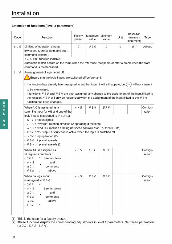
tLS Limiting of operation time at 0 25 0 s ø1 Adjust.low speed (zero setpoint and startcommand present).tLS = 0 : function inactive.Automatic restart occurs on the ramp when the reference reappears or after a break when the startcommand is reestablished.
LI2 Reassignment of logic input LI2
Ensure that the logic inputs are switched off beforehand.
- If a function has already been assigned to another input, it will still appear, but ENT will not cause it
to be memorized.- If functions PS2 and PS4 are both assigned, any change to the assignment of the input linked to
the function PS2 will only be recognized when the assignment of the input linked to the PS4function has been changed.
When AIC is assigned as a rrS PS4 OFF Configu-summing input for AI1 and one of the rationlogic inputs is assigned to PS2 (1) :- OFF : not assigned- rrS : "reverse" rotation direction (2 operating directions)- dCI : fixed DC injection braking (In speed controller for 5 s, then 0.5 Ith)- FSt : fast stop. This function is active when the input is switched off- JOG : jog operation (2)- PS2 : 2 preset speeds- PS4 : 4 preset speeds (2)
When AIC is assigned as rrS FSt OFF Configu-PI regulator feedback : ration- OFF See functions- rrS and- dCI comments- FSt above
When no logic input rrS PS2 OFF Configu-is assigned to PS2 : ration- OFF- rrS See functions- dCI and- FSt comments- JOG above- PS2
(1) This is the case for a factory preset.(2) These functions display the corresponding adjustments in level 1 parameters. Set these parameters
(JOG, SP2, SP4).
61
ENGLISH
Installation
Extension of functions (level 2 parameters)
Factory Maximum MinimumResolution
Code Functionpreset value value
Unit (minimum Typeincrement)
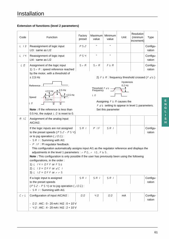
LI3 Reassignment of logic input PS2 " " Configu-LI3 : same as LI2 ration
LI4 Reassignment of logic input PS4 " " Configu-LI4 : same as LI2 ration
LO Assignment of the logic input SrA SrA FtA Configu-1) SrA : speed reference reached rationby the motor, with a threshold of± 2,5 Hz 2) FtA : frequency threshold crossed (Fdt)
Assigning FtA causes theFdt setting to appear in level 1 parameters.
Note : If the reference is less than Set this parameter0.5 Hz, the output LO is reset to 0.
AIC Assignment of the analog inputAIC/AI2.
If the logic inputs are not assigned SAI PIF SAI Configu-to the preset speeds (PS2 - PS4) rationor to jog operation (JOG) :- SAI : Summing with AI1- PIF : PI regulator feedback.
This configuration automatically assigns input AI1 as the regulator reference and displays theadjustments in the level 1 parameters : rPG, rIG, FbS.
Note : This configuration is only possible if the user has previously been using the followingconfigurations, in the order :1) LI4 = OFF or FSt2) LI3 = OFF or dCI3) LI2 = OFF or rrS
If a logic input is assigned SAI SAI SAI Configu-to the preset speeds ration(PS2 - PS4) or to jog operation (JOG) :- SAI : Summing with AI1
CrL Configuration of input AIC/AI2 : ø0 ‘0 ø0 mA Configu-ration
- ø0 : AIC : 0 - 20 mA / AI2 : 0 + 10 V- ‘0 : AIC : 4 - 20 mA / AI2 : 2 + 10 V
+2,5 Hz
+2,5 Hz -2,5 Hz
-2,5 Hz
Reference
Speed
Frequency
Hysteresis0.2 Hz
Threshold Fdt
LO
LO
62
ENGLISH
Installation
Extension of functions (level 2 parameters)
Factory Maximum MinimumResolution
Code Functionpreset value value
Unit (minimum Typeincrement)
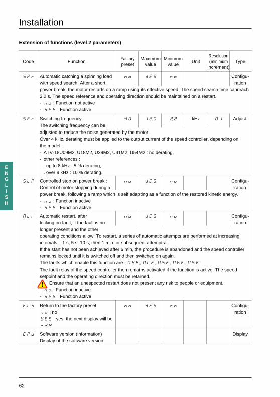
SPr Automatic catching a spinning load no YES no Configu-with speed search. After a short rationpower break, the motor restarts on a ramp using its effective speed. The speed search time canreach3.2 s. The speed reference and operating direction should be maintained on a restart.- no : Function not active- YES : Function active
SFr Switching frequency ‘0 1ë0 ë2 kHz ø1 Adjust.The switching frequency can beadjusted to reduce the noise generated by the motor.Over 4 kHz, derating must be applied to the output current of the speed controller, depending onthe model :- ATV-18U09M2, U18M2, U29M2, U41M2, U54M2 : no derating,- other references :
. up to 8 kHz : 5 % derating,
. over 8 kHz : 10 % derating.
StP Controlled stop on power break : no YES no Configu-Control of motor stopping during a rationpower break, following a ramp which is self adapting as a function of the restored kinetic energy.- no : Function inactive- YES : Function active
Atr Automatic restart, after no YES no Configu-locking on fault, if the fault is no rationlonger present and the otheroperating conditions allow. To restart, a series of automatic attempts are performed at increasingintervals : 1 s, 5 s, 10 s, then 1 min for subsequent attempts.If the start has not been achieved after 6 min, the procedure is abandoned and the speed controllerremains locked until it is switched off and then switched on again.The faults which enable this function are : OHF, OLF, USF, ObF, O5F.The fault relay of the speed controller then remains activated if the function is active. The speedsetpoint and the operating direction must be retained.
Ensure that an unespected restart does not present any risk to people or equipment.- no : Function inactive- YES : Function active
FCS Return to the factory preset no YES no Configu-no : no rationYES : yes, the next display will berdY
CPU Software version (information) DisplayDisplay of the software version
63
ENGLISH
Maintenance - Replacements and repairs
Before performing any operation on the speed controller, switch off the power supply and wait for thecapacitors to discharge (takes approximately 1 minute). The red indicator lamp should be off.
DC voltage to terminals PA and PB and hidden terminals PO, PC can reach 800 to 900 Vdepending on the mains voltage.
In case of a fault during installation or operation, firstly ensure that the guidelines relating to the environment,mounting and connections have been followed.
Maintenance
The Altivar 18 does not require any preventive maintenance. However, the user is advised to do the followingat regular intervals :
- check the state and tightness of connections,
- ensure that the temperature in the area around the equipment remains at an acceptable level, and thatventilation is effective (average lifetime of fans : 3 to 5 years depending on the conditions of use),
- ensure the speed controller is free from dust.
Maintenance assistance
The first fault detected is memorized and displayed on the display if the voltage is maintained : the speedcontroller locks itself and the fault relay trips.
Clearing the fault
Remove the power supply to the speed controller.Find the cause of the fault in order to eliminate it.Reconnect the power supply : this will clear the fault if it has been corrected.
In some cases the equipment may automatically restart after the fault has disappeared, if this function hasbeen programmed.
Replacements and repairs
For repairs and replacements on Altivar 18 speed controllers, consult your local Schneider office.
64
ENGLISH
Maintenance assistance
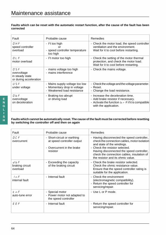
Faults which can be reset with the automatic restart function, after the cause of the fault has beencorrected
Fault Probable cause Remedies
OHF - I2t too high - Check the motor load, the speed controllerspeed controller or ventilation and the environment.overload - speed controller temperature Wait for it to cool before restarting.
too high
OLF - I2t motor too high - Check the setting of the motor thermalmotor overload protection, and check the motor load.
Wait for it to cool before restarting.
OSF - mains voltage too high - Check the mains voltage.overvoltage - mains interferencein steady stateor during acceleration
USF - Mains supply voltage too low - Check the voltage and the voltage parameter.under voltage - Momentary drop in voltage - Reset.
- Weakened load resistance - Change the load resistance.
ObF - Braking too abrupt - Increase the deceleration time.overvoltage or driving load - Add brake resistor if necessary.on deceleration - Activate the function brA if it is compatible
with the application.
Faults which cannot be automatically reset. The cause of the fault must be corrected before resettingby switching the controller off and then on again
Fault Probable cause Remedies
OCF - Short-circuit or earthing - Having disconnected the speed controller,overcurrent at speed controller output check the connection cables, motor isolation
and state of the windings.- Overcurrent in the brake - Check the resistor selected.
resistor Having disconnected the speed controller,check the connection cables, insulation ofthe resistor and its ohmic value.
dbF - Exceeding the capacity - Check the brake resistor selected.braking circuit of the braking circuit Check the ohmic resistance value.overload Ensure that the speed controller rating is
suitable for the application.
InF - Internal fault - Check the environmentinternal fault (electromagnetic compatibility).
- Return the speed controller forservicing/repair.
tnF - Special motor - Use L or P mode.auto-tune error - Power motor not adapted to
the speed controller
EEF - Internal fault - Return the speed controller forservicing/repair.

65
ENGLISH

75962 1997-07 VV
DE
D39
6037