Embed Size (px)
Citation preview
Guide d'exploitationUser's manualBedienungsanleitungGuía de explotación
Altivar 58Telemecanique
Variateurs de vitesse pour
moteurs asynchrones,
Variable speed controllers
for asynchronous motors,
Frequenzumrichter
für Drehstrom-Asynchronmotoren,
Variadores de velocidad
para motores asíncronos.
1
FRANÇAIS
Altivar 58
Variateur de vitesse pour moteurs asynchrones Page 2
Speed controller for asynchronous motors Page 34
Umrichter für Drehstrom-Asynchronmotoren Seite 66
Variador de velocidad para motores asíncronos Página 98
ENGLISH
DEUTSCH
ESPAÑOL
FRANÇAIS
34
ENGLISH
ATTENTION
NOTEThe speed controller is fitted with safety devices which, in the event of a fault, can shut down thespeed controller and consequently the motor. The motor itself may be stopped by a mechanicalblockage. Finally, voltage variations, especially line supply failures, can also cause shutdowns.
If the cause of the shutdown disappears, there is a risk of restarting which may endanger certainmachines or installations, especially those which must conform to safety regulations.
In this case the user must take precautions against the possibility of restarts, in particular byusing a low speed detector to cut off power to the speed controller if the motor performs anunprogrammed shutdown.
The design of equipment must conform to the requirements of IEC standards.
In general, the speed controller power supply must be disconnected before any operation oneither the electrical or mechanical parts of the installation or machine.
The products and equipment described in this document may be changed or modified at any time,either from a technical point of view or in the way they are operated. Their description can in noway be considered contractual.
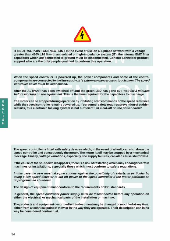
ATTENTIONIT NEUTRAL POINT CONNECTION : In the event of use on a 3-phase network with a voltagegreater than 480V ±10 % with an isolated or high-impedance system (IT), the internal EMC filtercapacitors which are connected to ground must be disconnected. Consult Schneider productsupport who are the only people qualified to perform this operation.
When the speed controller is powered up, the power components and some of the controlcomponents are connected to the line supply. It is extremely dangerous to touch them. The speedcontroller cover must be kept closed.
After the ALTIVAR has been switched off and the green LED has gone out, wait for 3 minutesbefore working on the equipment . This is the time required for the capacitors to discharge.
The motor can be stopped during operation by inhibiting start commands or the speed referencewhile the speed controller remains powered up. If personnel safety requires prevention of suddenrestarts, this electronic locking system is not sufficient : fit a cut-off on the power circuit.
35
ENGLISH
The speed controller must be installed and set up in accordance with both international andnational standards. Bringing the device into conformity is the responsibility of the systemsintegrator who must observe the EMC directive among others within the European Union.
The specifications contained in this document must be applied in order to comply with theessential requirements of the EMC directive.
Warning
The Altivar 58 must be considered as a component : it is neither a machine nor a device readyfor use in accordance with European directives (machinery directive and electromagneticcompatibility directive). It is the responsibility of the end user to ensure that the machine meetsthese standards.
Contents
Preliminar y recommendations 37
Selecting a Speed Contr oller with Heatsink and Built-in EMC Filter s 38
Selecting a Speed Contr oller with Heatsink,without EMC Filter s 40
Selecting a Speed Contr oller on a Baseplate with Built-in EMC Filter s 42
Technical Specifications 45
Dimensions - Mounting Recommendations 47
Mounting and Temperature Conditions 48
Removing the IP 41 Pr otective Blanking Co ver 50
Mounting in a Wall-fixing or Floor -standing Enc losure 51
Mounting in Wall-fixing or Floor -standing Enc losure - Speed Contr oller on Baseplate 52
Mounting on Mac hine Frame - Speed Contr oller on Baseplate 53
Electr omagnetic Compatibility - Mounting 54
Electr omagnetic Compatibility - Wiring 55
Access to Terminals - P ower Terminals 56
Contr ol Terminals 58
Connection Dia grams 59
Wiring Recommendations, Use 63
Setup 64
Operation - Maintenance - Spares and Repair s 65

36
ENGLISH
37
ENGLISH
Preliminary recommendations
Delivery
Check that the speed controller reference printed on the label is the same as that on the delivery notecorresponding to the purchase order.
Remove the Altivar 58 from its packaging and check that it has not been damaged in transit.
Handling and storage
To ensure the speed controller is protected before installation, handle and store the device in itspackaging.
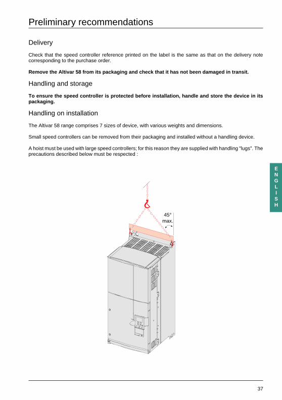
Handling on installation
The Altivar 58 range comprises 7 sizes of device, with various weights and dimensions.
Small speed controllers can be removed from their packaging and installed without a handling device.
A hoist must be used with large speed controllers; for this reason they are supplied with handling "lugs”. Theprecautions described below must be respected :
45°max.
38
ENGLISH
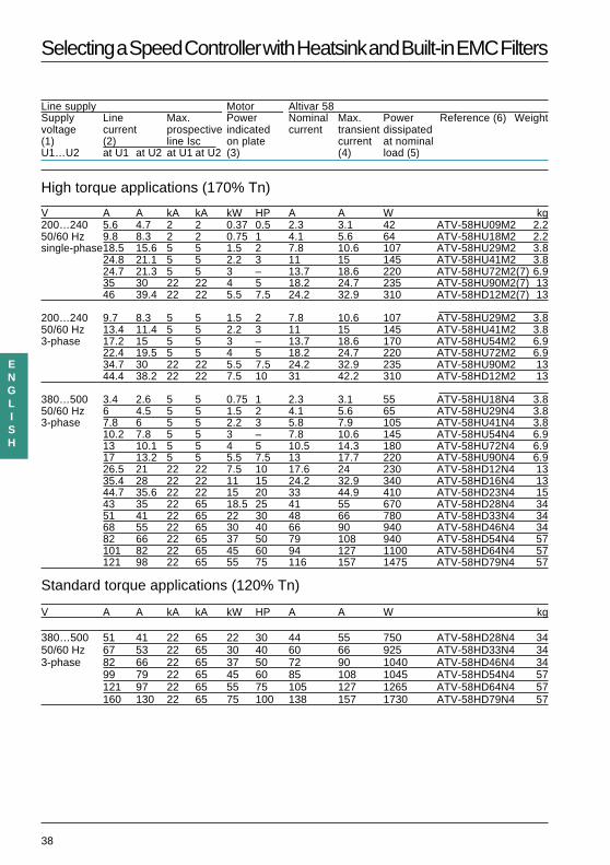
Selecting a Speed Controller with Heatsink and Built-in EMC Filters
Line supply Motor Altivar 58Supply Line Max. Power Nominal Max. Power Reference (6) Weightvoltage current prospective indicated current transient dissipated(1) (2) line Isc on plate current at nominalU1…U2 at U1 at U2 at U1 at U2 (3) (4) load (5)
High torque applications (170% Tn)
V A A kA kA kW HP A A W kg200…240 5.6 4.7 2 2 0.37 0.5 2.3 3.1 42 ATV-58HU09M2 2.250/60 Hz 9.8 8.3 2 2 0.75 1 4.1 5.6 64 ATV-58HU18M2 2.2single-phase18.5 15.6 5 5 1.5 2 7.8 10.6 107 ATV-58HU29M2 3.8
24.8 21.1 5 5 2.2 3 11 15 145 ATV-58HU41M2 3.824.7 21.3 5 5 3 – 13.7 18.6 220 ATV-58HU72M2(7) 6.935 30 22 22 4 5 18.2 24.7 235 ATV-58HU90M2(7) 1346 39.4 22 22 5.5 7.5 24.2 32.9 310 ATV-58HD12M2(7) 13
200…240 9.7 8.3 5 5 1.5 2 7.8 10.6 107 ATV-58HU29M2 3.850/60 Hz 13.4 11.4 5 5 2.2 3 11 15 145 ATV-58HU41M2 3.83-phase 17.2 15 5 5 3 – 13.7 18.6 170 ATV-58HU54M2 6.9
22.4 19.5 5 5 4 5 18.2 24.7 220 ATV-58HU72M2 6.934.7 30 22 22 5.5 7.5 24.2 32.9 235 ATV-58HU90M2 1344.4 38.2 22 22 7.5 10 31 42.2 310 ATV-58HD12M2 13
380…500 3.4 2.6 5 5 0.75 1 2.3 3.1 55 ATV-58HU18N4 3.850/60 Hz 6 4.5 5 5 1.5 2 4.1 5.6 65 ATV-58HU29N4 3.83-phase 7.8 6 5 5 2.2 3 5.8 7.9 105 ATV-58HU41N4 3.8
10.2 7.8 5 5 3 – 7.8 10.6 145 ATV-58HU54N4 6.913 10.1 5 5 4 5 10.5 14.3 180 ATV-58HU72N4 6.917 13.2 5 5 5.5 7.5 13 17.7 220 ATV-58HU90N4 6.926.5 21 22 22 7.5 10 17.6 24 230 ATV-58HD12N4 1335.4 28 22 22 11 15 24.2 32.9 340 ATV-58HD16N4 1344.7 35.6 22 22 15 20 33 44.9 410 ATV-58HD23N4 1543 35 22 65 18.5 25 41 55 670 ATV-58HD28N4 3451 41 22 65 22 30 48 66 780 ATV-58HD33N4 3468 55 22 65 30 40 66 90 940 ATV-58HD46N4 3482 66 22 65 37 50 79 108 940 ATV-58HD54N4 57101 82 22 65 45 60 94 127 1100 ATV-58HD64N4 57121 98 22 65 55 75 116 157 1475 ATV-58HD79N4 57
Standard torque applications (120% Tn)
V A A kA kA kW HP A A W kg
380…500 51 41 22 65 22 30 44 55 750 ATV-58HD28N4 3450/60 Hz 67 53 22 65 30 40 60 66 925 ATV-58HD33N4 343-phase 82 66 22 65 37 50 72 90 1040 ATV-58HD46N4 34
99 79 22 65 45 60 85 108 1045 ATV-58HD54N4 57121 97 22 65 55 75 105 127 1265 ATV-58HD64N4 57160 130 22 65 75 100 138 157 1730 ATV-58HD79N4 57
39
ENGLISH
Selecting a Speed Controller with Heatsink and Built-in EMC Filters
(1) Nominal supply voltages : min. U1, max. U2.
(2) Typical value for a 4-pole motor with no additional choke except in single-phase for ATV-58PU72M2,U90M2 and D12M2 (7).
(3) These power levels are for a maximum switching frequency of 2 to 4 kHz, depending on the rating, andcontinuous operation. Switching frequencies are detailed in the section on "Technical Specifications".
Using the ATV-58 with a higher switching frequency :
• For continuous operation derate by one power rating, for example : ATV-58PU09M2 for 0.25 kW – ATV-58PU18N4 for 0.37 kW – ATV-58PD12N4 for 5.5 kW.
• If no power derating is applied, do not exceed the following operating conditions : Cumulative running time 36 s maximum per 60 s cycle (load factor 60 %).
(4) For 60 seconds.
(5) These power levels are given for the maximum permissible switching frequency in continuous operation(2 or 4 kHz, depending on the rating).
(6) Speed controllers ordered under references ATV-58PiiiM2 and ATV-58PiiiN4 are supplied with adisplay module.Speed controllers ordered under the same references ending in Z (ATV-58PiiiiiZ) are supplied withouta display module.The additional letter Z only appears on the packaging.
(7) • A line choke must be used if the speed controllers are to be connected to a single-phase line supply(see selection table in catalog).• The "Supply phase loss" fault, code IPL, must be configured to "No" for these 3-phase speed controllersto operate on a single-phase supply. If this fault remains in its factory set-up (Yes), the speed controllerwill remain locked on a "PHF" fault.
40
ENGLISH
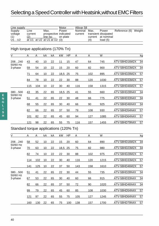
Selecting a Speed Controller with Heatsink,without EMC Filters
Line supply Motor Altivar 58Supply Line Max. Power Nominal Max. Power Reference (6) Weightvoltage current prospective indicated current transient dissipated(1) (2) line Isc on plate current at nominalU1…U2 at U1 at U2 at U1 at U2 (3) (4) load (5)
High torque applications (170% Tn)
V A A kA kA kW HP A A W kg
208…240 43 40 10 22 11 15 47 64 745 ATV-58HD16M2X 3450/60 Hz3-phase 59 54 10 22 15 20 60 82 900 ATV-58HD23M2X 34
71 64 10 22 18,5 25 75 102 895 ATV-58HD28M2X 57
84 78 10 22 22 30 88 120 1030 ATV-58HD33M2X 57
115 104 10 22 30 40 116 158 1315 ATV-58HD46M2X 57
380…500 43 35 22 65 18,5 25 41 55 660 ATV-58HD28N4X 3450/60 Hz3-phase 51 41 22 65 22 30 48 66 775 ATV-58HD33N4X 34
68 55 22 65 30 40 66 90 925 ATV-58HD46N4X 34
82 66 22 65 37 50 79 108 930 ATV-58HD54N4X 57
101 82 22 65 45 60 94 127 1085 ATV-58HD64N4X 57
121 98 22 65 55 75 116 157 1455 ATV-58HD79N4X 57
Standard torque applications (120% Tn)
V A A kA kA kW HP A A W kg
208…240 58 52 10 22 15 20 60 64 890 ATV-58HD16M2X 3450/60 Hz3-phase 70 63 10 22 18,5 25 75 82 980 ATV-58HD23M2X 34
82 74 10 22 22 30 88 102 975 ATV-58HD28M2X 57
114 102 10 22 30 40 116 120 1215 ATV-58HD33M2X 57
141 125 10 22 37 50 143 158 1610 ATV-58HD46M2X 57
380…500 51 41 22 65 22 30 44 55 735 ATV-58HD28N4X 3450/60 Hz3-phase 67 53 22 65 30 40 60 66 915 ATV-58HD33N4X 34
82 66 22 65 37 50 72 90 1020 ATV-58HD46N4X 34
99 79 22 65 45 60 85 108 1030 ATV-58HD54N4X 57
121 97 22 65 55 75 105 127 1245 ATV-58HD64N4X 57
160 130 22 65 75 100 138 157 1700 ATV-58HD79N4X 57
41
ENGLISH
Selecting a Speed Controller with Heatsink, without EMC Filters
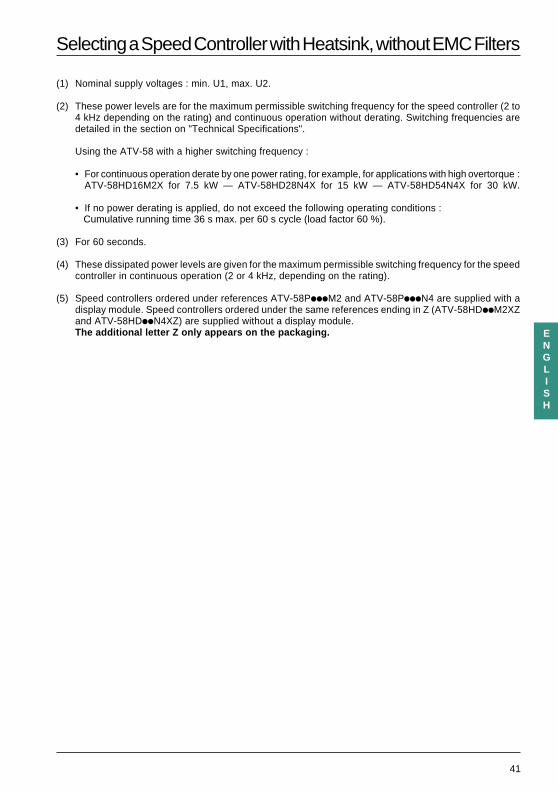
(1) Nominal supply voltages : min. U1, max. U2.
(2) These power levels are for the maximum permissible switching frequency for the speed controller (2 to4 kHz depending on the rating) and continuous operation without derating. Switching frequencies aredetailed in the section on "Technical Specifications".
Using the ATV-58 with a higher switching frequency :
• For continuous operation derate by one power rating, for example, for applications with high overtorque :ATV-58HD16M2X for 7.5 kW — ATV-58HD28N4X for 15 kW — ATV-58HD54N4X for 30 kW.
• If no power derating is applied, do not exceed the following operating conditions : Cumulative running time 36 s max. per 60 s cycle (load factor 60 %).
(3) For 60 seconds.
(4) These dissipated power levels are given for the maximum permissible switching frequency for the speedcontroller in continuous operation (2 or 4 kHz, depending on the rating).
(5) Speed controllers ordered under references ATV-58PiiiM2 and ATV-58PiiiN4 are supplied with adisplay module. Speed controllers ordered under the same references ending in Z (ATV-58HDiiM2XZand ATV-58HDiiN4XZ) are supplied without a display module.The additional letter Z only appears on the packaging.
42
ENGLISH
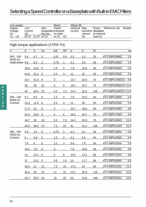
Selecting a Speed Controller on a Baseplate with Built-in EMC Filters
Line supply Motor Altivar 58Supply Line Max. Power Nominal Max. Power Reference (6) Weightvoltage current prospective indicated current transient dissipated(1) (2) line Isc on plate current at nominalU1…U2 at U1 at U2 at U1 at U2 (3) (4) load (5)
High torque applications (170% Tn)
V A A kA kW HP A A W kg
200…240 5.6 4.7 2 0.37 0.5 2.3 3.1 25 ATV-58PU09M2 1.850/60 Hzsingle-phase 9.8 8.3 2 0.75 1 4.1 5.6 30 ATV-58PU18M2 1.8
18.5 15.6 5 1.5 2 7.8 10.6 40 ATV-58PU29M2 2.9
24.8 21.1 5 2.2 3 11 15 50 ATV-58PU41M2 2.9
24.7 21.3 5 3 – 13.7 18.6 70 ATV-58PU72M2(7) 4.8
35 30 22 4 5 18.2 24.7 75 ATV-58PU90M2(7) 11.5
46 39.4 22 5.5 7.5 24.2 32.9 100 ATV-58PD12M2(7) 11.5
200…240 9.7 8.3 5 1.5 2 7.8 10.6 40 ATV-58PU29M2 2.950/60 Hz3-phase 13.4 11.4 5 2.2 3 11 15 50 ATV-58PU41M2 2.9
17.2 15 5 3 – 13.7 18.6 60 ATV-58PU54M2 4.8
22.4 19.5 5 4 5 18.2 24.7 70 ATV-58PU72M2 4.8
34.7 30 22 5.5 7.5 24.2 32.9 75 ATV-58PU90M2 11.5
44.4 38.2 22 7.5 10 31 42.2 100 ATV-58PD12M2 11.5
380…500 3.4 2.6 5 0.75 1 2.3 3.1 35 ATV-58PU18N4 2.950/60 Hz3-phase 6 4.5 5 1.5 2 4.1 5.6 40 ATV-58PU29N4 2.9
7.8 6 5 2.2 3 5.8 7.9 50 ATV-58PU41N4 2.9
10.2 7.8 5 3 – 7.8 10.6 55 ATV-58PU54N4 4.8
13 10.1 5 4 5 10.5 14.3 65 ATV-58PU72N4 4.8
17 13.2 5 5.5 7.5 13 17.7 80 ATV-58PU90N4 4.8
26.5 21 22 7.5 10 17.6 24 90 ATV-58PD12N4 11.5
35.4 28 22 11 15 24.2 32.9 110 ATV-58PD16N4 11.5
44.7 35.6 22 15 20 33 44.9 140 ATV-58PD23N4 13.5
43
ENGLISH
Selecting a Speed Controller on a Baseplate with Built-in EMC Filters
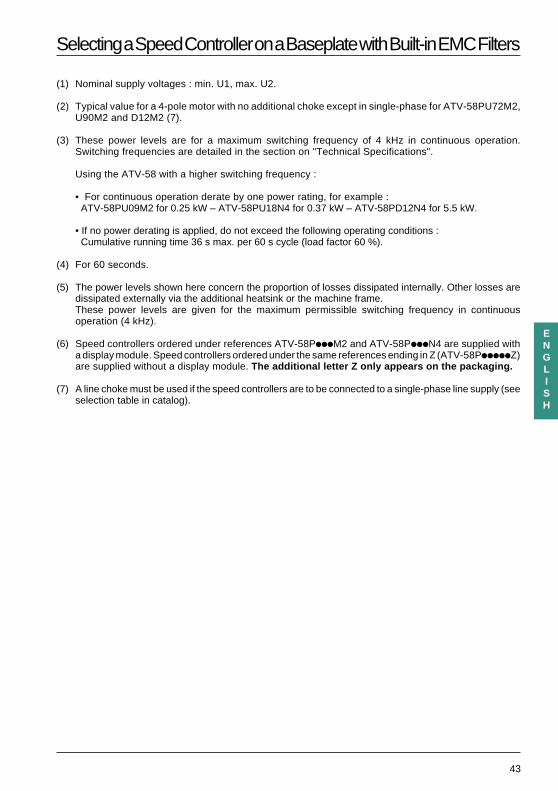
(1) Nominal supply voltages : min. U1, max. U2.
(2) Typical value for a 4-pole motor with no additional choke except in single-phase for ATV-58PU72M2,U90M2 and D12M2 (7).
(3) These power levels are for a maximum switching frequency of 4 kHz in continuous operation.Switching frequencies are detailed in the section on "Technical Specifications".
Using the ATV-58 with a higher switching frequency :
• For continuous operation derate by one power rating, for example : ATV-58PU09M2 for 0.25 kW – ATV-58PU18N4 for 0.37 kW – ATV-58PD12N4 for 5.5 kW.
• If no power derating is applied, do not exceed the following operating conditions : Cumulative running time 36 s max. per 60 s cycle (load factor 60 %).
(4) For 60 seconds.
(5) The power levels shown here concern the proportion of losses dissipated internally. Other losses aredissipated externally via the additional heatsink or the machine frame.These power levels are given for the maximum permissible switching frequency in continuousoperation (4 kHz).
(6) Speed controllers ordered under references ATV-58PiiiM2 and ATV-58PiiiN4 are supplied witha display module. Speed controllers ordered under the same references ending in Z (ATV-58PiiiiiZ)are supplied without a display module. The additional letter Z only appears on the packaging.
(7) A line choke must be used if the speed controllers are to be connected to a single-phase line supply (seeselection table in catalog).
44
ENGLISH
Available Torque
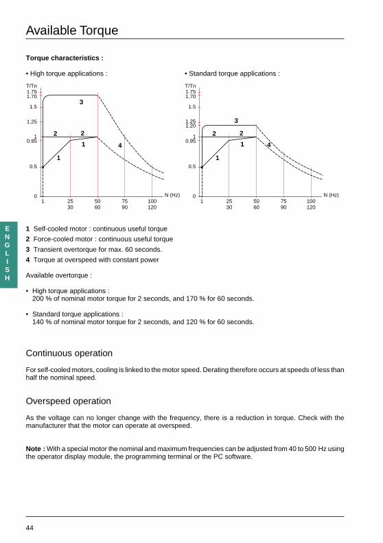
Torque characteristics :
• High torque applications : • Standard torque applications :
1 Self-cooled motor : continuous useful torque
2 Force-cooled motor : continuous useful torque
3 Transient overtorque for max. 60 seconds.
4 Torque at overspeed with constant power
Available overtorque :
• High torque applications :200 % of nominal motor torque for 2 seconds, and 170 % for 60 seconds.
• Standard torque applications :140 % of nominal motor torque for 2 seconds, and 120 % for 60 seconds.
Continuous operation
For self-cooled motors, cooling is linked to the motor speed. Derating therefore occurs at speeds of less thanhalf the nominal speed.
Overspeed operation
As the voltage can no longer change with the frequency, there is a reduction in torque. Check with themanufacturer that the motor can operate at overspeed.
Note : With a special motor the nominal and maximum frequencies can be adjusted from 40 to 500 Hz usingthe operator display module, the programming terminal or the PC software.
0 N (Hz)
0.5
2530
5060
1
3
2 2
1
1
10.95
1.5
1.701.75T/Tn
1.25
7590
100120
4
0 N (Hz)
0.5
2530
5060
1
3
2 2
1
1
10.95
1.5
1.701.75T/Tn
1.251.20
7590
100120
4
45
ENGLISH
Technical Specifications
Environment
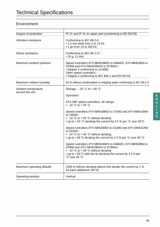
Degree of protection IP 21 and IP 41 on upper part (conforming to EN 50178)
Vibration resistance Conforming to IEC 68-2-6 :• 1.5 mm peak from 2 to 13 Hz• 1 gn from 13 to 200 Hz.
Shock resistance Conforming to IEC 68-2-27 :• 15 g, 11 ms)
Maximum ambient pollution Speed controllers ATV-58HD16M2X to D46M2X, ATV-58HD28N4 toD79N4 and ATV-58HD28N4X to D79N4X :• Degree 3 conforming to UL508COther speed controllers :• Degree 2 conforming to IEC 664-1 and EN 50718.
Maximum relative humidity 93 % without condensation or dripping water conforming to IEC 68-2-3
Ambient temperature Storage : - 25 °C to + 65 °Caround the unit
Operation :
ATV-58P speed controllers, all ratings :• - 10 °C to + 40 °C
Speed controllers ATV-58HU09M2 to U72M2 and ATV-58HU18N4to U90N4 :• - 10 °C to + 50 °C without derating• up to + 60 °C derating the current by 2.2 % per °C over 50°C
Speed controllers ATV-58HU90M2 to D12M2 and ATV-58HD12N4to D23N4 :• - 10 °C to + 40 °C without derating• up to + 50 °C derating the current by 2.2 % per °C over 40 °C
Speed controllers ATV-58HD16M2X to D46M2X, ATV-58HD28N4 toD79N4 and ATV-58HD28N4X to D79N4X :• - 10 °C to + 40 °C without derating• up to + 60 °C with fan kit derating the current by 2.2 % per°C over 40 °C
Maximum operating altitude 1000 m without derating (above this derate the current by 1 %for each additional 100 m)
Operating position Vertical
46
ENGLISH
Technical Specifications
Electrical specifications
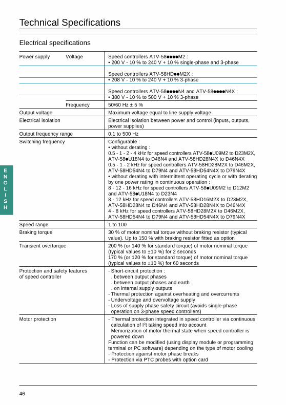
Power supply Voltage Speed controllers ATV-58iiiiM2 :• 200 V - 10 % to 240 V + 10 % single-phase and 3-phase
Speed controllers ATV-58HDiiM2X :• 208 V - 10 % to 240 V + 10 % 3-phase
Speed controllers ATV-58iiiiN4 and ATV-58iiiiN4X :• 380 V - 10 % to 500 V + 10 % 3-phase
Frequency 50/60 Hz ± 5 %
Output voltage Maximum voltage equal to line supply voltage
Electrical isolation Electrical isolation between power and control (inputs, outputs,power supplies)
Output frequency range 0.1 to 500 Hz
Switching frequency Configurable :• without derating :0.5 - 1 - 2 - 4 kHz for speed controllers ATV-58iU09M2 to D23M2X,ATV-58iU18N4 to D46N4 and ATV-58HD28N4X to D46N4X0.5 - 1 - 2 kHz for speed controllers ATV-58HD28M2X to D46M2X,ATV-58HD54N4 to D79N4 and ATV-58HD54N4X to D79N4X• without derating with intermittent operating cycle or with deratingby one power rating in continuous operation :8 - 12 - 16 kHz for speed controllers ATV-58iU09M2 to D12M2and ATV-58iU18N4 to D23N48 - 12 kHz for speed controllers ATV-58HD16M2X to D23M2X,ATV-58HD28N4 to D46N4 and ATV-58HD28N4X to D46N4X4 - 8 kHz for speed controllers ATV-58HD28M2X to D46M2X,ATV-58HD54N4 to D79N4 and ATV-58HD54N4X to D79N4X
Speed range 1 to 100
Braking torque 30 % of motor nominal torque without braking resistor (typicalvalue). Up to 150 % with braking resistor fitted as option
Transient overtorque 200 % (or 140 % for standard torque) of motor nominal torque(typical values to ±10 %) for 2 seconds170 % (or 120 % for standard torque) of motor nominal torque(typical values to ±10 %) for 60 seconds
Protection and safety features - Short-circuit protection :of speed controller . between output phases
. between output phases and earth
. on internal supply outputs- Thermal protection against overheating and overcurrents- Undervoltage and overvoltage supply- Loss of supply phase safety circuit (avoids single-phase
operation on 3-phase speed controllers)
Motor protection - Thermal protection integrated in speed controller via continuouscalculation of I2t taking speed into accountMemorization of motor thermal state when speed controller ispowered down
Function can be modified (using display module or programmingterminal or PC software) depending on the type of motor cooling- Protection against motor phase breaks- Protection via PTC probes with option card
47
ENGLISH
Dimensions - Mounting Recommendations
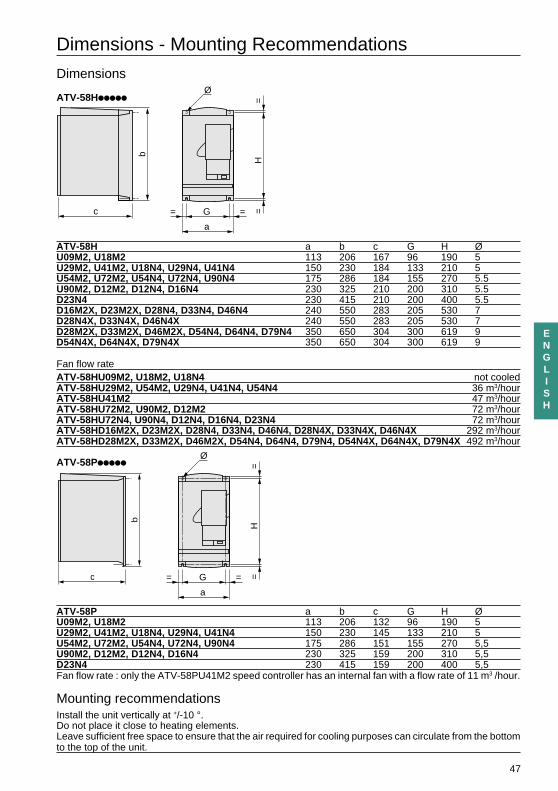
Dimensions
ATV-58Hiiiii
ATV-58H a b c G H ØU09M2, U18M2 113 206 167 96 190 5U29M2, U41M2, U18N4, U29N4, U41N4 150 230 184 133 210 5U54M2, U72M2, U54N4, U72N4, U90N4 175 286 184 155 270 5.5U90M2, D12M2, D12N4, D16N4 230 325 210 200 310 5.5D23N4 230 415 210 200 400 5.5D16M2X, D23M2X, D28N4, D33N4, D46N4 240 550 283 205 530 7D28N4X, D33N4X, D46N4X 240 550 283 205 530 7D28M2X, D33M2X, D46M2X, D54N4, D64N4, D79N4 350 650 304 300 619 9D54N4X, D64N4X, D79N4X 350 650 304 300 619 9
Fan flow rateATV-58HU09M2, U18M2, U18N4 not cooledATV-58HU29M2, U54M2, U29N4, U41N4, U54N4 36 m3/hourATV-58HU41M2 47 m3/hourATV-58HU72M2, U90M2, D12M2 72 m3/hourATV-58HU72N4, U90N4, D12N4, D16N4, D23N4 72 m3/hourATV-58HD16M2X, D23M2X, D28N4, D33N4, D46N4, D28N4X, D33N4X, D46N4X 292 m3/hourATV-58HD28M2X, D33M2X, D46M2X, D54N4, D64N4, D79N4, D54N4X, D64N4X, D79N4X 492 m3/hour
ATV-58Piiiii
ATV-58P a b c G H ØU09M2, U18M2 113 206 132 96 190 5U29M2, U41M2, U18N4, U29N4, U41N4 150 230 145 133 210 5U54M2, U72M2, U54N4, U72N4, U90N4 175 286 151 155 270 5,5U90M2, D12M2, D12N4, D16N4 230 325 159 200 310 5,5D23N4 230 415 159 200 400 5,5Fan flow rate : only the ATV-58PU41M2 speed controller has an internal fan with a flow rate of 11 m3 /hour.
Mounting recommendationsInstall the unit vertically at +/-10 °.Do not place it close to heating elements.Leave sufficient free space to ensure that the air required for cooling purposes can circulate from the bottomto the top of the unit.
c
b
a
G
Ø
= =
H=
=
c
b
a
G
Ø
= =
H=
=
48
ENGLISH
Mounting and Temperature Conditions
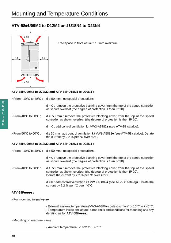
ATV-58iiiiiU09M2 to D12M2 and U18N4 to D23N4
Free space in front of unit : 10 mm minimum.
ATV-58HU09M2 to U72M2 and ATV-58HU18N4 to U90N4 :
• From - 10°C to 40°C : d ≥ 50 mm : no special precautions.
d = 0 : remove the protective blanking cover from the top of the speed controlleras shown overleaf (the degree of protection is then IP 20).
• From 40°C to 50°C : d ≥ 50 mm : remove the protective blanking cover from the top of the speedcontroller as shown overleaf (the degree of protection is then IP 20).
d = 0 : add control ventilation kit VW3-A5882i (see ATV-58 catalog).
• From 50°C to 60°C : d ≥ 50 mm : add control ventilation kit VW3-A5882i (see ATV-58 catalog). Deratethe current by 2.2 % per °C over 50°C.
ATV-58HU90M2 to D12M2 and ATV-58HD12N4 to D23N4 :
• From - 10°C to 40°C : d ≥ 50 mm : no special precautions.
d = 0 : remove the protective blanking cover from the top of the speed controlleras shown overleaf (the degree of protection is then IP 20).
• From 40°C to 50°C : d ≥ 50 mm : remove the protective blanking cover from the top of the speedcontroller as shown overleaf (the degree of protection is then IP 20).Derate the current by 2.2 % per °C over 40°C.
d = 0 : add control ventilation kit VW3-A5882i (see ATV-58 catalog). Derate thecurrent by 2.2 % per °C over 40°C.
ATV-58Piiiiiiiiiiiiiiiiiiii :
• For mounting in enclosure
- External ambient temperature (VW3-A5880i coolest surface) : - 10°C to + 40°C.- Temperature inside enclosure : same limits and conditions for mounting and anyderating as for ATV-58Hiiii.
• Mounting on machine frame :
- Ambient temperature : -10°C to + 40°C.
≥ d ≥ d
≥ 50
≥ 50
49
ENGLISH
Mounting and Temperature Conditions
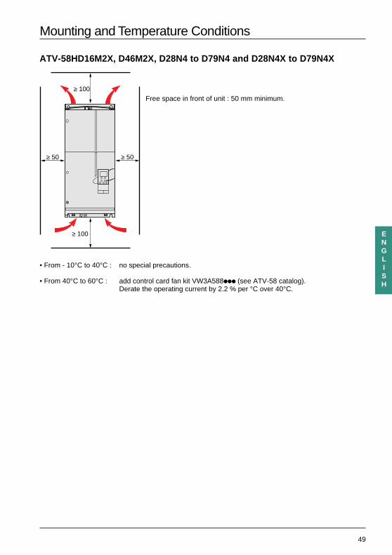
ATV-58HD16M2X, D46M2X, D28N4 to D79N4 and D28N4X to D79N4X
Free space in front of unit : 50 mm minimum.
• From - 10°C to 40°C : no special precautions.
• From 40°C to 60°C : add control card fan kit VW3A588iii (see ATV-58 catalog).Derate the operating current by 2.2 % per °C over 40°C.
≥ 50 ≥ 50
≥ 100
≥ 100
50
ENGLISH
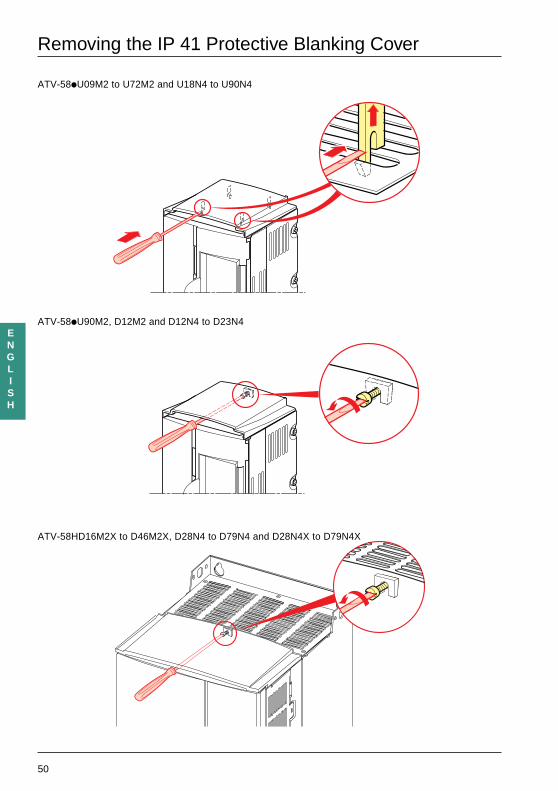
Removing the IP 41 Protective Blanking Cover
ATV-58iU09M2 to U72M2 and U18N4 to U90N4
ATV-58iU90M2, D12M2 and D12N4 to D23N4
ATV-58HD16M2X to D46M2X, D28N4 to D79N4 and D28N4X to D79N4X
51
ENGLISH
Mounting in a Wall-fixing or Floor-standing Enclosure
Observe the mounting recommendations on the previous page.
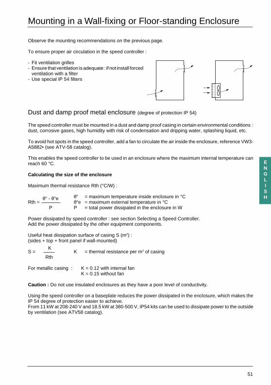
To ensure proper air circulation in the speed controller :
- Fit ventilation grilles- Ensure that ventilation is adequate : if not install forced
ventilation with a filter- Use special IP 54 filters
Dust and damp proof metal enclosure (degree of protection IP 54)
The speed controller must be mounted in a dust and damp proof casing in certain environmental conditions :dust, corrosive gases, high humidity with risk of condensation and dripping water, splashing liquid, etc.
To avoid hot spots in the speed controller, add a fan to circulate the air inside the enclosure, reference VW3-A5882• (see ATV-58 catalog).
This enables the speed controller to be used in an enclosure where the maximum internal temperature canreach 60 °C.
Calculating the size of the enclosure
Maximum thermal resistance Rth (°C/W) :
θ° = maximum temperature inside enclosure in °CRth =
θ° - θ°eθ°e = maximum external temperature in °C
P P = total power dissipated in the enclosure in W
Power dissipated by speed controller : see section Selecting a Speed Controller.Add the power dissipated by the other equipment components.
Useful heat dissipation surface of casing S (m2) :(sides + top + front panel if wall-mounted)
S =K
K = thermal resistance per m2 of casingRth
For metallic casing : K = 0.12 with internal fanK = 0.15 without fan
Caution : Do not use insulated enclosures as they have a poor level of conductivity.
Using the speed controller on a baseplate reduces the power dissipated in the enclosure, which makes theIP 54 degree of protection easier to achieve.From 11 kW at 208-240 V and 18.5 kW at 380-500 V, IP54 kits can be used to dissipate power to the outsideby ventilation (see ATV58 catalog).
52
ENGLISH
Mounting in Wall-fixing or Floor-standing Enclosure - SpeedController on Baseplate
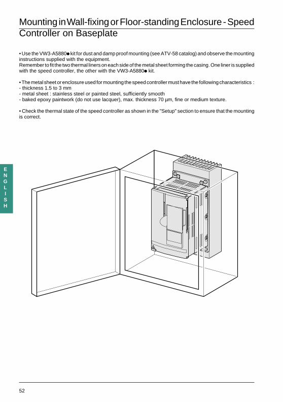
• Use the VW3-A5880i kit for dust and damp proof mounting (see ATV-58 catalog) and observe the mountinginstructions supplied with the equipment.Remember to fit the two thermal liners on each side of the metal sheet forming the casing. One liner is suppliedwith the speed controller, the other with the VW3-A5880i kit.
• The metal sheet or enclosure used for mounting the speed controller must have the following characteristics :- thickness 1.5 to 3 mm- metal sheet : stainless steel or painted steel, sufficiently smooth- baked epoxy paintwork (do not use lacquer), max. thickness 70 µm, fine or medium texture.
• Check the thermal state of the speed controller as shown in the "Setup" section to ensure that the mountingis correct.
53
ENGLISH
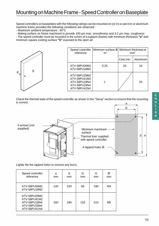
Mounting on Machine Frame - Speed Controller on Baseplate
Speed controllers on baseplates with the following ratings can be mounted on (or in) a cast iron or aluminummachine frame provided the following conditions are observed :- Maximum ambient temperature : 40°C- Mating surface on frame machined to provide 100 µm max. smoothness and 3.2 µm max. roughness.- The speed controller must be mounted in the centre of a support (frame) with minimum thickness "e" andminimum square cooling surface "S" exposed to the open air.
Speed controller Minimum surface S Minimum thickness ereference m2 mm2
Cast iron Aluminum
ATV-58PU09M2 0.25 20 10ATV-58PU18M2
ATV-58PU29M2ATV-58PU41M2ATV-58PU18N4 1 20ATV-58PU29N4ATV-58PU41N4
Check the thermal state of the speed controller as shown in the "Setup" section to ensure that the mountingis correct.
Lightly file the tapped holes to remove any burrs.
Speed controller a b G H Øreference mm mm mm mm mm
ATV-58PU09M2 120 220 96 190 M4ATV-58PU18M2
ATV-58PU29M2ATV-58PU41M2ATV-58PU18N4 160 240 133 210 M5ATV-58PU29N4ATV-58PU41N4
e S
a
G
bH
Minimum machinedsurface
4 tapped holes Ø
Thermal liner suppliedwith speed controller
4 screws (notsupplied)
54
ENGLISH
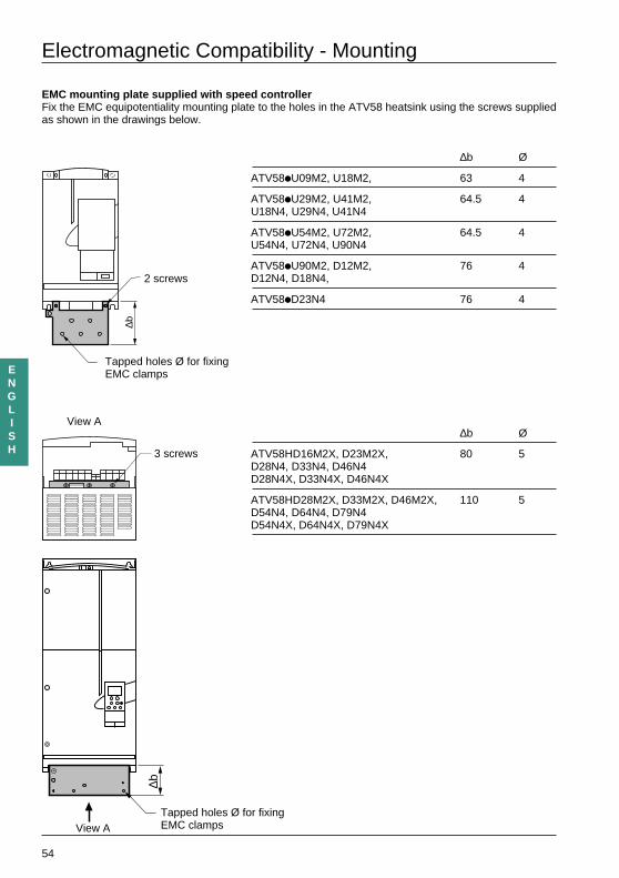
Electromagnetic Compatibility - Mounting
EMC mounting plate supplied with speed controllerFix the EMC equipotentiality mounting plate to the holes in the ATV58 heatsink using the screws suppliedas shown in the drawings below.
∆b Ø
ATV58iU09M2, U18M2, 63 4
ATV58iU29M2, U41M2, 64.5 4U18N4, U29N4, U41N4
ATV58iU54M2, U72M2, 64.5 4U54N4, U72N4, U90N4
ATV58iU90M2, D12M2, 76 4D12N4, D18N4,
ATV58iD23N4 76 4
∆b Ø
ATV58HD16M2X, D23M2X, 80 5D28N4, D33N4, D46N4D28N4X, D33N4X, D46N4X
ATV58HD28M2X, D33M2X, D46M2X, 110 5D54N4, D64N4, D79N4D54N4X, D64N4X, D79N4X
Tapped holes Ø for fixingEMC clamps
∆b
∆b
View A
3 screws
View A
2 screws
Tapped holes Ø for fixingEMC clamps
55
ENGLISH
Electromagnetic Compatibility - Wiring
Principle
• Grounds between speed controller, motor and cable shielding must have "high frequency" equipotentiality.
• Use shielded cables with shielding connected to the ground at 360° at both ends of the motor cable, brakingresistor (if fitted) and control-command cables. Conduit or metal ducting can be used for part of the shieldinglength provided that there is no break in continuity.
• Ensure maximum separation between the power supply cable (line supply) and the motor cable.
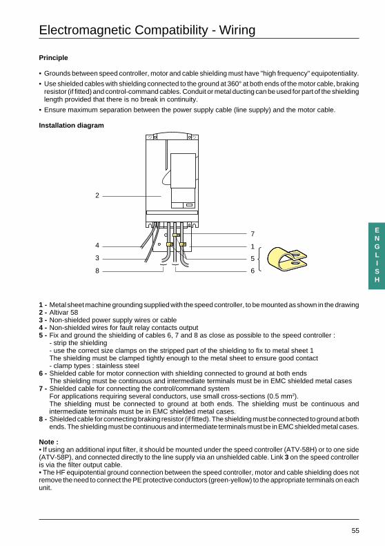
Installation diagram
1 - Metal sheet machine grounding supplied with the speed controller, to be mounted as shown in the drawing2 - Altivar 583 - Non-shielded power supply wires or cable4 - Non-shielded wires for fault relay contacts output5 - Fix and ground the shielding of cables 6, 7 and 8 as close as possible to the speed controller :
- strip the shielding- use the correct size clamps on the stripped part of the shielding to fix to metal sheet 1The shielding must be clamped tightly enough to the metal sheet to ensure good contact- clamp types : stainless steel
6 - Shielded cable for motor connection with shielding connected to ground at both endsThe shielding must be continuous and intermediate terminals must be in EMC shielded metal cases
7 - Shielded cable for connecting the control/command systemFor applications requiring several conductors, use small cross-sections (0.5 mm2).The shielding must be connected to ground at both ends. The shielding must be continuous andintermediate terminals must be in EMC shielded metal cases.
8 - Shielded cable for connecting braking resistor (if fitted). The shielding must be connected to ground at bothends. The shielding must be continuous and intermediate terminals must be in EMC shielded metal cases.
Note :• If using an additional input filter, it should be mounted under the speed controller (ATV-58H) or to one side(ATV-58P), and connected directly to the line supply via an unshielded cable. Link 3 on the speed controlleris via the filter output cable.• The HF equipotential ground connection between the speed controller, motor and cable shielding does notremove the need to connect the PE protective conductors (green-yellow) to the appropriate terminals on eachunit.
4
2
8 6
7
5
1
3
56
ENGLISH
Access to Terminals - Power Terminals
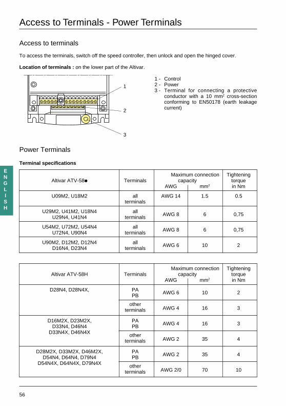
Access to terminals
To access the terminals, switch off the speed controller, then unlock and open the hinged cover.
Location of terminals : on the lower part of the Altivar.
1 - Control2 - Power3 - Terminal for connecting a protective
conductor with a 10 mm2 cross-sectionconforming to EN50178 (earth leakagecurrent)
Power Terminals
Terminal specifications
Maximum connection TighteningAltivar ATV-58i Terminals capacity torque
AWG mm2 in Nm
U09M2, U18M2 all AWG 14 1.5 0.5terminals
U29M2, U41M2, U18N4 allU29N4, U41N4 terminals AWG 8 6 0,75
U54M2, U72M2, U54N4 allU72N4, U90N4 terminals AWG 8 6 0,75
U90M2, D12M2, D12N4 allD16N4, D23N4 terminals AWG 6 10 2
Maximum connection TighteningAltivar ATV-58H Terminals capacity torque
AWG mm2 in Nm
D28N4, D28N4X, PA AWG 6 10 2PB
otherterminals AWG 4 16 3
D16M2X, D23M2X, PA AWG 4 16 3D33N4, D46N4 PBD33N4X, D46N4X other
terminals AWG 2 35 4
D28M2X, D33M2X, D46M2X, PA AWG 2 35 4D54N4, D64N4, D79N4 PBD54N4X, D64N4X, D79N4X other
terminals AWG 2/0 70 10
1
2
3
57
ENGLISH
Power Terminals
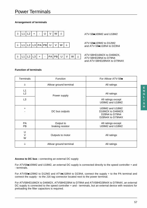
Arrangement of terminals
ATV-58iU09M2 and U18M2
ATV-58iU29M2 to D12M2and ATV-58iU18N4 to D23N4
ATV-58HD16M2X to D46M2X,ATV-58HD28N4 to D79N4and ATV-58HD28N4X to D79N4X
Function of terminals
Terminals Function For Altivar ATV-58i
s Altivar ground terminal All ratings
L1L2
Power supplyAll ratings
L3 All ratings exceptU09M2 and U18M2
+ U09M2 and U18M2- DC bus outputs D16M2X to D46M2X
D28N4 to D79N4D28N4X to D79N4X
PA Output to All ratings exceptPB braking resistor U09M2 and U18M2
UV Outputs to motor All ratingsW
s Altivar ground terminal All ratings
Access to DC bus : connecting an external DC supply
For ATV58iU09M2 and U18M2, an external DC supply is connected directly to the speed controller + and- terminals.
For ATV58iU29M2 to D12M2 and ATViU18N4 to D23N4, connect the supply + to the PA terminal andconnect the supply - to the J16 tag connector located next to the power terminal.
For ATV58HD16M2X to D46M2X, ATV58HD28N4 to D79N4 and ATV58HD28N4X to D79N4X, an externalDC supply is connected to the speed controller + and - terminals, but an external device with resistors forpreloading the filter capacitors is required.
PA PBL1 L2 L3s U V W s
L1 L2s + -
+ -
U V W s
PA PBL1 L2 L3s U V W s
58
ENGLISH
Control Terminals
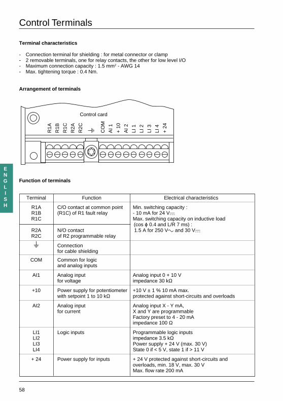
Terminal characteristics
- Connection terminal for shielding : for metal connector or clamp- 2 removable terminals, one for relay contacts, the other for low level I/O- Maximum connection capacity : 1.5 mm2 - AWG 14- Max. tightening torque : 0.4 Nm.
Arrangement of terminals
Function of terminals
Terminal Function Electrical characteristics
R1A C/O contact at common point Min. switching capacity :R1B (R1C) of R1 fault relay - 10 mA for 24 VaR1C Max. switching capacity on inductive load
(cos ϕ 0.4 and L/R 7 ms) :R2A N/O contact 1.5 A for 250 Vc and 30 VaR2C of R2 programmable relay
s Connectionfor cable shielding
COM Common for logicand analog inputs
AI1 Analog input Analog input 0 + 10 Vfor voltage impedance 30 kΩ
+10 Power supply for potentiometer +10 V ± 1 % 10 mA max.with setpoint 1 to 10 kΩ protected against short-circuits and overloads
AI2 Analog input Analog input X - Y mA,for current X and Y are programmable
Factory preset to 4 - 20 mAimpedance 100 Ω
LI1 Logic inputs Programmable logic inputsLI2 impedance 3.5 kΩLI3 Power supply + 24 V (max. 30 V)LI4 State 0 if < 5 V, state 1 if > 11 V
+ 24 Power supply for inputs + 24 V protected against short-circuits andoverloads, min. 18 V, max. 30 VMax. flow rate 200 mA
R1A
R1B
R1C
R2A
R2C s CO
M
AI 1
+ 1
0
AI 2
LI 1
LI 2
LI 3
LI 4
+ 2
4
Control card
59
ENGLISH
Connection Diagrams
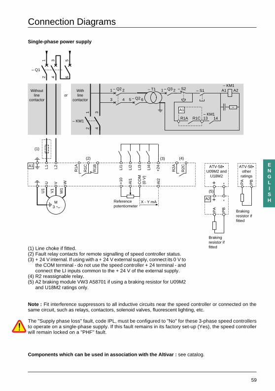
Single-phase power supply
(1) Line choke if fitted.(2) Fault relay contacts for remote signalling of speed controller status.(3) + 24 V internal. If using with a + 24 V external supply, connect its 0 V to
the COM terminal - do not use the speed controller + 24 terminal - andconnect the LI inputs common to the + 24 V of the external supply.
(4) R2 reassignable relay.(5) A2 braking module VW3 A58701 if using a braking resistor for U09M2
and U18M2 ratings only.
Note : Fit interference suppressors to all inductive circuits near the speed controller or connected on thesame circuit, such as relays, contactors, solenoid valves, fluorescent lighting, etc.
The "Supply phase loss" fault, code IPL, must be configured to "No" for these 3-phase speed controllersto operate on a single-phase supply. If this fault remains in its factory set-up (Yes), the speed controllerwill remain locked on a "PHF" fault.
Components which can be used in association with the Altivar : see catalog.
U V W +10
AI1
CO
M(0
V)
L1U
1
W1
V1
M 3 c
L2
R1A
R1C
R1B LI1
LI2
LI3
LI4
+24
AI2
(3)
X - Y mA
(2)
R2A
R2C
(4)
(1)
– KM1
Withoutline
contactoror
Withline
contactor
12
34
– Q1
12
34
56
– KM1A2A1– S1– S2
13R1CR1A 14– KM1
– T1– Q21 2 – Q31 2
3 4 – Q25 6
A1
A1
Referencepotentiometer
Brakingresistor iffitted
ATV-58•other
ratings
PA
PB
+ -
+ -
(5)
A2
PA
PB
ATV-58•U09M2 and
U18M2
Brakingresistor iffitted
60
ENGLISH
Connection Diagrams
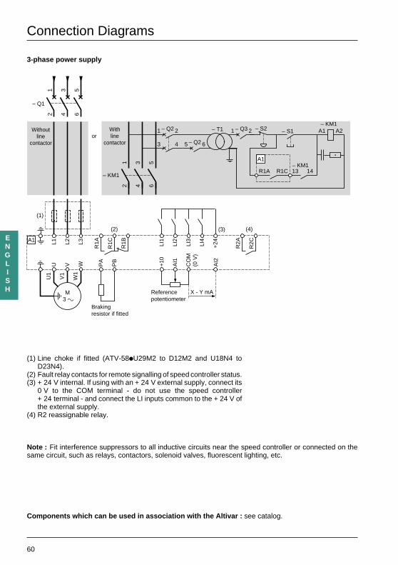
3-phase power supply
(1) Line choke if fitted (ATV-58iU29M2 to D12M2 and U18N4 toD23N4).
(2) Fault relay contacts for remote signalling of speed controller status.(3) + 24 V internal. If using with an + 24 V external supply, connect its
0 V to the COM terminal - do not use the speed controller+ 24 terminal - and connect the LI inputs common to the + 24 V ofthe external supply.
(4) R2 reassignable relay.
Note : Fit interference suppressors to all inductive circuits near the speed controller or connected on thesame circuit, such as relays, contactors, solenoid valves, fluorescent lighting, etc.
U V W PA
PB
+10
AI1
CO
M(0
V)
L1U
1
W1
V1
M 3 c
L2 L3
R1A
R1C
R1B LI1
LI2
LI3
LI4
+24
AI2
(3)
X - Y mA
(2)
R2A
R2C
(4)
(1)
– Q1
12
34
56
A1
– KM1
Withoutline
contactoror
Withline
contactor
12
34
56
– KM1A2A1– S1– S2
13R1CR1A 14– KM1
– T1– Q21 2 – Q31 2
3 4 – Q25 6
A1
Referencepotentiometer
Brakingresistor if fitted
Components which can be used in association with the Altivar : see catalog.
61
ENGLISH
Connection Diagrams
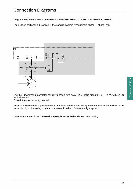
Diagram with downstream contactor for ATV-58 iU09M2 to D12M2 and U18N4 to D23N4 UUU
The shaded part should be added to the various diagram types (single-phase, 3-phase, etc).
Use the "downstream contactor control" function with relay R2, or logic output LO (a 24 V) with an I/Oextension card.Consult the programming manual.
Note : Fit interference suppressors to all inductive circuits near the speed controller or connected on thesame circuit, such as relays, contactors, solenoid valves, fluorescent lighting, etc.
Components which can be used in association with the Altivar : see catalog.
U V W
U1
W1
V1
M 3 c
A1
A2
A1
R2C
– KM2
12
34
56
R2ACO
M(0
V)
+24
62
ENGLISH
Connection Diagrams
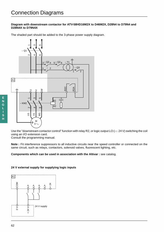
Diagram with downstream contactor for ATV-58HD16M2X to D46M2X, D28N4 to D79N4 andD28N4X to D79N4X
The shaded part should be added to the 3-phase power supply diagram.
Use the "downstream contactor control" function with relay R2, or logic output LO (a 24 V) switching the coilusing an I/O extension card.Consult the programming manual.
Note : Fit interference suppressors to all inductive circuits near the speed controller or connected on thesame circuit, such as relays, contactors, solenoid valves, fluorescent lighting, etc.
Components which can be used in association with the Altivar : see catalog.
24 V external supply for supplying logic inputs
U V W
U1
W1
V1
M 3 c
A1
A1
A2
R2C
– KM2
12
34
56
R2A
– Q1
12
34
56
– T1– Q23 4
– Q3
1 21 2
– Q25 6
LI•
LI•
LI•
LI•
+ 2
4
CO
M0
V
+ 2
4 V
A1
24 V supply
63
ENGLISH
Wiring Recommendations, Use
Wiring recommendations, use
Power
Observe the cable cross-sectional areas recommended in the standards.
The speed controller must be earthed to conform with the regulations concerning high leakage currents (over3.5 mA). Do not use a residual current device for upstream protection on account of the DC elements whichmay be generated by leakage currents. If the installation involves several speed controllers on the same line,each speed controller must be earthed separately. If necessary, fit a line choke (consult the catalog).
Keep the power cables separate from circuits in the installation with low-level signals (detectors, PLCs,measuring apparatus, video, telephone).
Control
Keep the control circuits and the power cables apart. For control and speed reference circuits, we recommendusing shielded twisted cables with a pitch of between 25 and 50 mm, connecting the shielding to each end.
Recommendations for use
In power control mode using a line contactor :
- Do not switch contactor KM1 frequently (otherwise premature aging of the filtering capacitorswill occur) and use inputs LI1 to LI4 to control the speed controller.
- If the cycles are longer than 60 s these measures are absolutely necessary .
If safety standards necessitate isolation of the motor, fit a contactor on the speed controller output and usethe "downstream contactor control" function (consult the programming manual).
Fault relay, unlocking
The fault relay is energized when the speed controller is powered up and is not faulty. It has one C/O contactat the common point.
The speed controller is unlocked after a fault by :
- powering down the speed controller until both the display and indicator lamps go out, then powering upagain
- automatically or remotely via logic input : consult the programming manual.
Programmable I/O, functions :
Consult the programming manual.
64
ENGLISH
Setup
The Altivar is factory preset for the most common operating conditions.
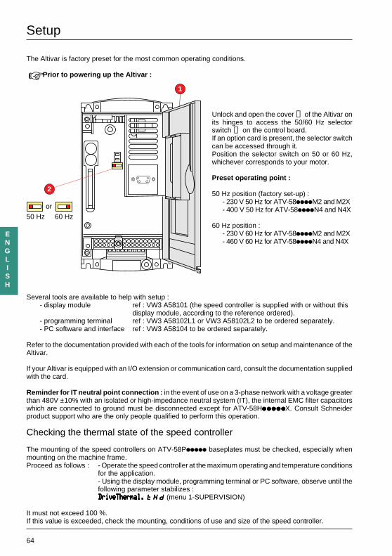
Prior to powering up the Altivar :
Unlock and open the cover ➀ of the Altivar onits hinges to access the 50/60 Hz selectorswitch ➁ on the control board.If an option card is present, the selector switchcan be accessed through it.Position the selector switch on 50 or 60 Hz,whichever corresponds to your motor.
Preset operating point :
50 Hz position (factory set-up) :- 230 V 50 Hz for ATV-58iiiiM2 and M2X- 400 V 50 Hz for ATV-58iiiiN4 and N4X
60 Hz position :- 230 V 60 Hz for ATV-58iiiiM2 and M2X- 460 V 60 Hz for ATV-58iiiiN4 and N4X
Several tools are available to help with setup :- display module ref : VW3 A58101 (the speed controller is supplied with or without this
display module, according to the reference ordered).- programming terminal ref : VW3 A58102L1 or VW3 A58102L2 to be ordered separately.- PC software and interface ref : VW3 A58104 to be ordered separately.
Refer to the documentation provided with each of the tools for information on setup and maintenance of theAltivar.
If your Altivar is equipped with an I/O extension or communication card, consult the documentation suppliedwith the card.
Reminder for IT neutral point connection : in the event of use on a 3-phase network with a voltage greaterthan 480V ±10% with an isolated or high-impedance neutral system (IT), the internal EMC filter capacitorswhich are connected to ground must be disconnected except for ATV-58HiiiiiiiiiiiiiiiiiiiiiiiiiX. Consult Schneiderproduct support who are the only people qualified to perform this operation.
Checking the thermal state of the speed controller
The mounting of the speed controllers on ATV-58Piiiii baseplates must be checked, especially whenmounting on the machine frame.Proceed as follows : - Operate the speed controller at the maximum operating and temperature conditions
for the application.- Using the display module, programming terminal or PC software, observe until thefollowing parameter stabilizes :DriveThermal.DriveThermal.DriveThermal.DriveThermal.DriveThermal. tHdtHdtHdtHdtHd (menu 1-SUPERVISION)
It must not exceed 100 %.If this value is exceeded, check the mounting, conditions of use and size of the speed controller.
2
1
50 Hz 60 Hz
or
65
ENGLISH
Operation - Maintenance - Spares and Repairs
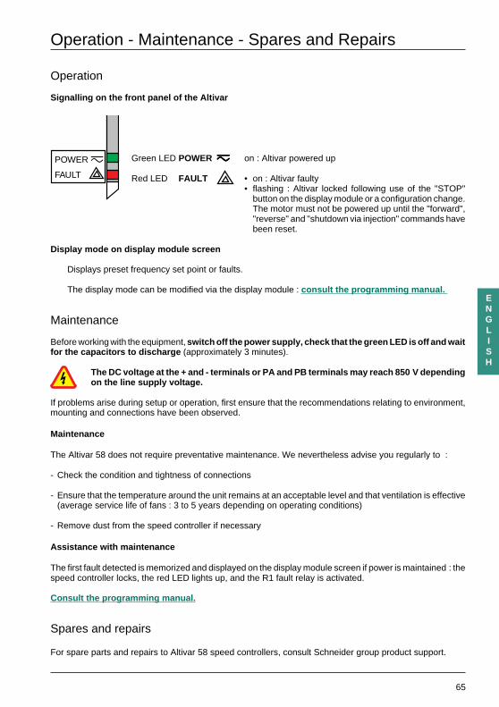
Operation
Signalling on the front panel of the Altivar
Green LED POWER zzzzz on : Altivar powered up
Red LED FAULT • on : Altivar faulty• flashing : Altivar locked following use of the "STOP"
button on the display module or a configuration change.The motor must not be powered up until the "forward","reverse" and "shutdown via injection" commands havebeen reset.
Display mode on display module screen
Displays preset frequency set point or faults.
The display mode can be modified via the display module : consult the programming manual.
Maintenance
Before working with the equipment, switch off the power supply, check that the green LED is off and waitfor the capacitors to discharge (approximately 3 minutes).
The DC voltage at the + and - terminals or PA and PB terminals may reach 850 V dependingon the line supply voltage.
If problems arise during setup or operation, first ensure that the recommendations relating to environment,mounting and connections have been observed.
Maintenance
The Altivar 58 does not require preventative maintenance. We nevertheless advise you regularly to :
- Check the condition and tightness of connections
- Ensure that the temperature around the unit remains at an acceptable level and that ventilation is effective(average service life of fans : 3 to 5 years depending on operating conditions)
- Remove dust from the speed controller if necessary
Assistance with maintenance
The first fault detected is memorized and displayed on the display module screen if power is maintained : thespeed controller locks, the red LED lights up, and the R1 fault relay is activated.
Consult the programming manual.
Spares and repairs
For spare parts and repairs to Altivar 58 speed controllers, consult Schneider group product support.
FAULT
POWER z

VVDED397048 W9 1493588 01 11 A04
82476 1999-05


![(Présentation Altivar 32 [Mode de compatibilité]) - RPMI](https://img.pdfslide.fr/doc/110x75/586e15f51a28ab3f0a8c4652/presentation-altivar-32-mode-de-compatibilite-rpmi.jpg)