Embed Size (px)
Citation preview
Venterre - Parc éolien de New Richmond Annexes - Volume 3 Étude d'impact sur l'environnement - Mars 2009
ANNEXE C
ÉTUDE GÉOTECHNIQUE PRÉLIMINAIRE

KWATROE CONSULTANTS INC.
Preliminary Geotechnical Investigation Windmill Park
St-Alphonse, Quebec
Date : July 19, 2007 Réf. / Ref. : Q021135-A1
INSPEC-SOL INC. 192, montée Industrielle-et-Commerciale, Rimouski (Québec) G5M 1A5 ♦ Tél. : (418) 724-7030 ♦Téléc. / Fax : (418) 724-7057 ♦SMQ ISO 9001 : 2000
Reference No. Q021135-A1 July 19, 2007 Mr. Casey Kennedy Kwatroe Consultants Inc. 13 des Cerisiers Street Gaspé, Quebec G4X 2M1
Re: Preliminary Geotechnical Investigation Windmill Park St-Alphonse, Quebec
Dear Mr. Kennedy: We are pleased to forward our report covering our preliminary geotechnical investigation carried out at the above noted site. The objective of the study was to characterize the soil and bedrock at the site of the proposed windmill locations., and provide comments and recommendations concerning admissible bearing capacities and recommended foundations.
1.0 METHODOLOGY
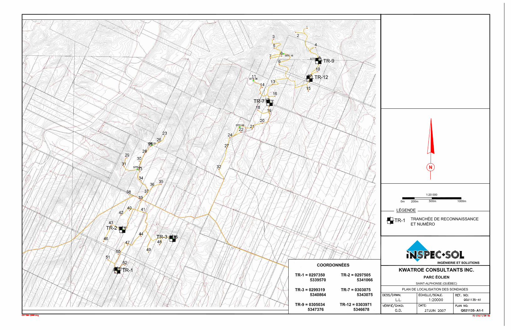
The site work consisted of the excavation of six (6) test pits by small backhoe at locations chosen by the Client, who was present during the site work. The position of the test pits was measured using GPS, accurate to within 2 m of their actual locations. It should be noted that the number of the test pits correspond to the numbering of the proposed windmills as indicated on the plan provided. The test pit locations are shown on the attached Plan No. Q021135-A1-1. The test pit logs are presented on Enclosure Nos. 1 to 6, all included in the attached Appendix. During the site work, representative bulk samples of the sub-soils were obtained for further identification purposes in our laboratory. The site work was conducted on June 20, 2007, under the constant supervision of our geotechnical personnel.
Montréal ♦ Mont-Tremblant ♦ St-Bruno ♦ Thetford Mines ♦ Québec ♦ Lévis ♦ Rimouski ♦ Matane ♦ Ottawa ♦ Kingston ♦ Toronto ♦ Waterloo ♦ Windsor ♦ Détroit www.inspecsol.com
Reference No. Q021135-A1
TABLE OF CONTENTS
1.0 METHODOLOGY ........................................................................................................ 1
2.0 SUMMARY DESCRIPTION OF SOILS AND BEDROCK ..................................... 2
3.0 GROUNDWATER ........................................................................................................ 3
4.0 RECOMENDATIONS AND PRELIMINARY COMMENTS.................................. 3
4.1 WINDMILL FOUNDATIONS ................................................................................ 3 4.1.1 Foundations Upon Soil or Bedrock ................................................. 3 4.1.2 Foundations Anchored in Bedrock .................................................. 4
4.2 CRANE PLATFORMS FOR ERECTING WINDMILLS .............................................. 4 4.3 FURTHER STUDIES ............................................................................................ 4
5.0 LIMITATIONS OF THE INVESTIGATION ......................................................... 5
APPENDIX Test Pit Location Plan (Plan No. Q021135-A1-1) Test Pit Logs (Enclosure Nos. 1 to 6)
Reference No. Q021135-A1 2
2.0 SUMMARY DESCRIPTION OF SOILS AND BEDROCK
Table No.1 presents the coordinates of the test pit locations. Table No. 2 summarizes the subsoil and bedrock stratigraphy.
Table No. 1 Coordinates of Test Pit Locations
Coordinates Test Pit No.
East North TP-1 297 350 m 5 339 570 m TP-2 297 505 m 5 341 066 m TP-3 299 319 m 5 340 864 m TP-7 303 075 m 5 345 856 m TP-9 305 034 m 5 347 376 m
TP-12 303 971 m 5 346 678 m
Table No.2
Summary of Subsoil and bedrock Stratigraphy Test Pit No. Overburden (sub-soils) Bedrock
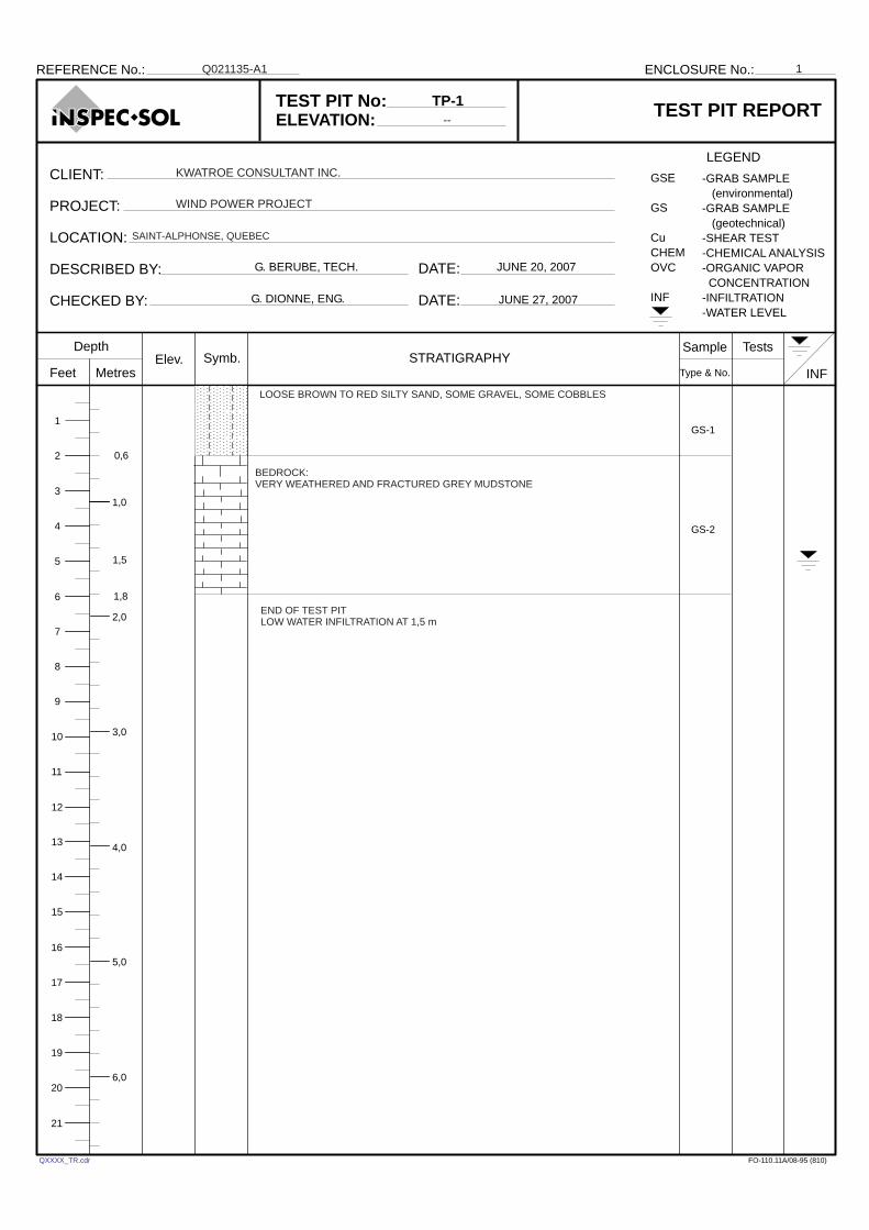
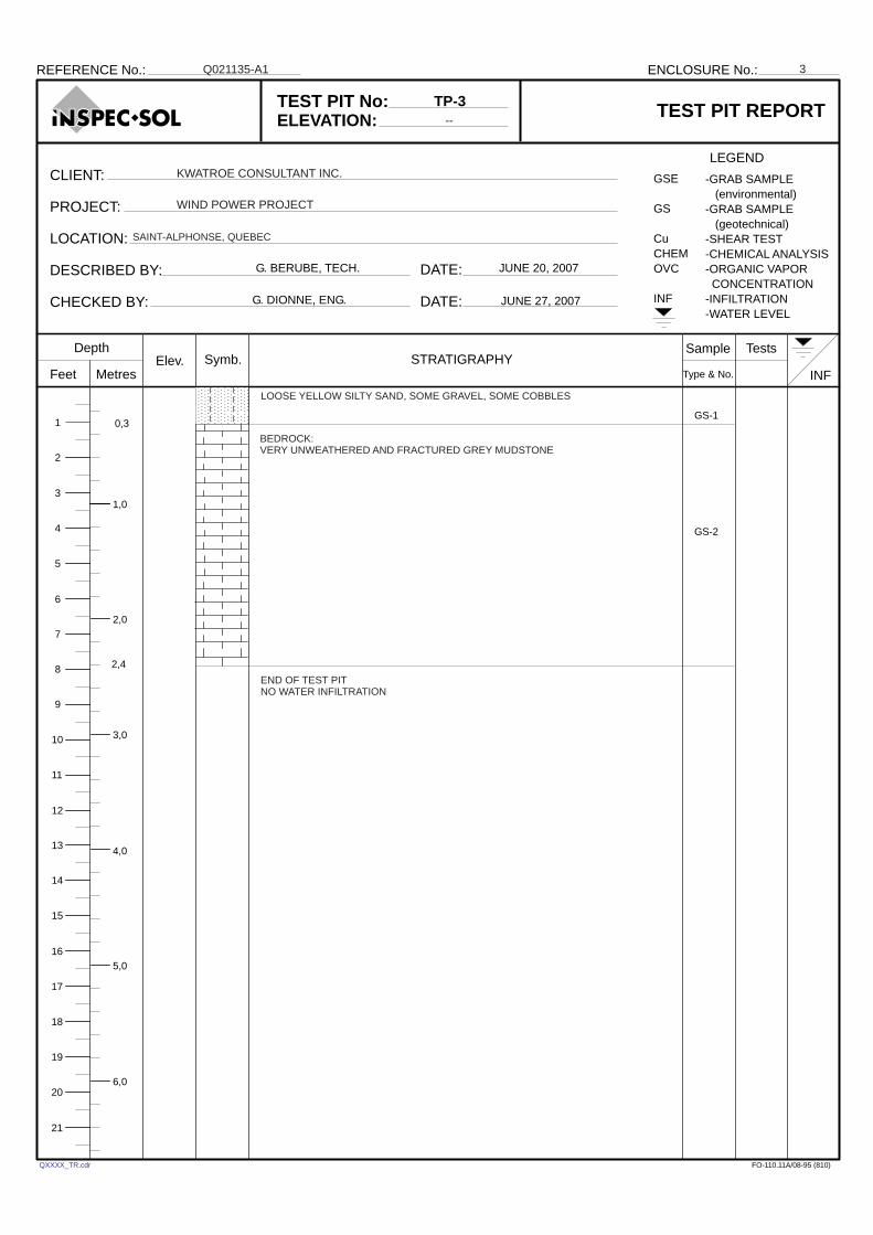
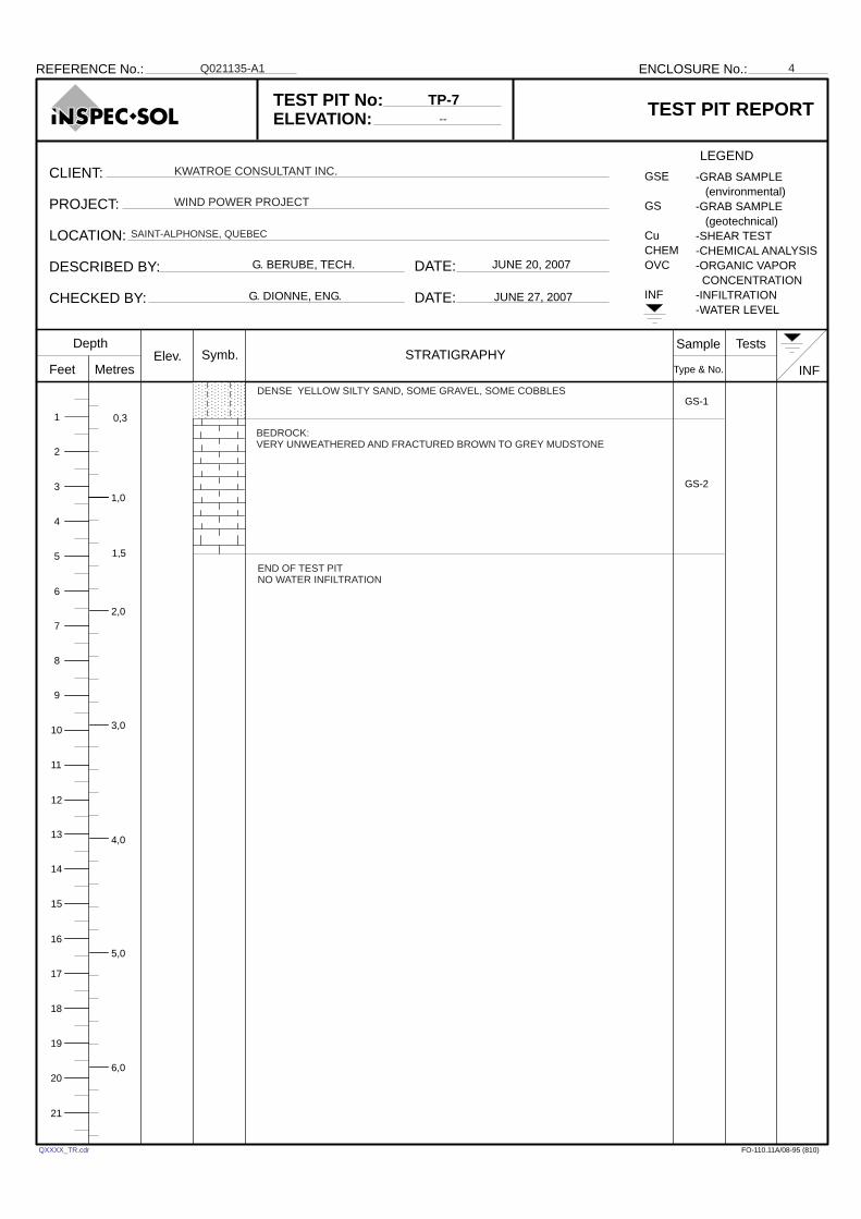
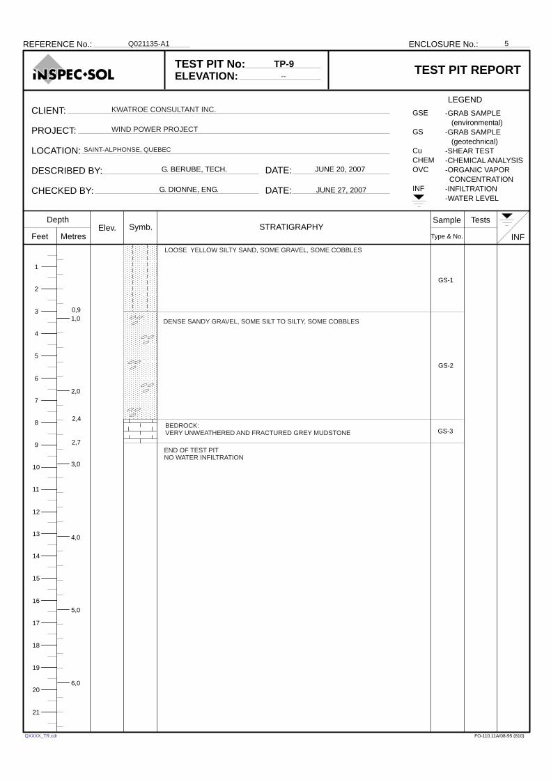
TP-1 0.0 – 0.6 m 0.6 – 1.8 m TP-2 0.0 – 1.8 m 1.8 – 2.1 m TP-3 0.0 – 0.3 m 0.3 – 2.4 m TP-7 0.0 – 0.3 m 0.3 – 1.5 m TP-9 0.0 – 2.4 m 2.4 – 2.7 m
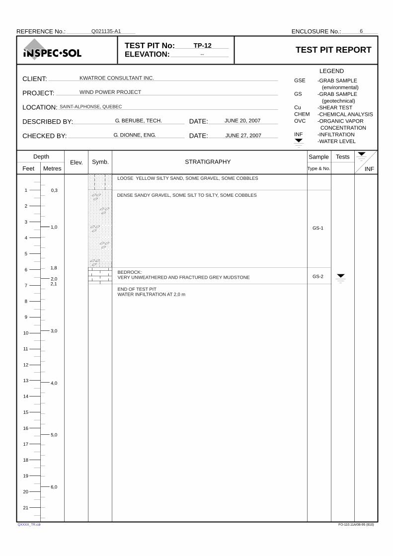
TP-12 0.0 – 1.8 m 1.8 – 2.1 m
The overburden is comprised principally of till deposits consisting of gravel, sand and silt in varying proportions. The compaction of the materials is considered as dense. Underlying the overburden is bedrock consisting of very altered and fractured grey mudstone. In Test Pit Nos. TP-1, TP-3 and TP-7, the rock was excavated by the bucket of the backhoe to depths of more than 1.0 m. All of the test pits were terminated within the bedrock at depths ranging from 1.5 m to 2.4 m.
Reference No. Q021135-A1 3
3.0 GROUNDWATER
During the excavation, water infiltration was observed in Test Pit Nos. TP-1, TP-2 and TP-12, at depths of 1.5 m, 2.1 m, and 2.0 m, respectively. No water infiltration was observed in the remaining test pits. The depth of water in the sub-soils will vary according to the time of year and prevailing weather conditions.
4.0 RECOMENDATIONS AND PRELIMINARY COMMENTS
According to information provided the project will consist of the construction of 53 windmills with a projected capacity of 1.5 MW, spread over an area occupying 2.5 km by 5.5 km. At the time of the preparation of this report, the exact nature of the proposed foundations (dimensions, soil constraints, etc.) were not known.
4.1 Windmill Foundations
Based on the test pits, two types of foundations may be envisaged for this project. These would be either foundations set upon the sub-soils or bedrock, or anchored into bedrock. Our recommendations for each are as follows:
4.1.1 Foundations Upon Soil or Bedrock
Assuming that the foundations of the windmills are founded at the minimum depth of 2.2 m for frost protection, these can rest upon the dense soils or fractured/altered bedrock. The following bearing capacities can be used for concrete foundations set on either material. Concrete foundations on dense soil: 200 kPa Concrete foundations on altered/fractured bedrock: 500 kPa
Under these constraints, the settlements of the foundations should not exceed the normally accepted standard for windmills, of 3 mm/m. This value is valid only for foundations set upon non-remoulded soils, free of mud or loose material. We recommend that provisions be made for the installation of a base of lean concrete immediately following the excavation for the foundations.
Reference No. Q021135-A1 4
4.1.2 Foundations Anchored in Bedrock
Alternatively, the foundations can be anchored into bedrock. In order to validate this option, we recommend that several boreholes be put down to verify the quality of bedrock with depth. Generally, for sound rock of this type, a bond factor of 75 lbs/in2 to 150 lbs/in2 between bedrock and grout can be obtained for the anchors. The length of the anchors must be calculated taking into account, the upper 2 m of fractured and altered bedrock will offer no pullout resistance.
4.2 Crane Platforms For Erecting Windmills
Based on available information from similar projects, the crane platforms require sub-soils having a minimum admissible bearing capacity of 300 kPa. However, a bearing capacity minimum of 150 kPa is required when the crane is moving. Given the subsoil and bedrock characteristics, these values can be obtained within the till deposit or on shallow bedrock at all locations. The preparation of the bases of the excavations for the cranes should be performed as follows: Strip all organic topsoil and remove all tree roots and stumps. If required, raise the surface using the excavated materials (till or rock, during dry periods
of the year only) placed in layers not exceeding 300 mm, compacted to 98% of its Modified Dry Proctor density.
Place a layer of MG-112 crushed stone or equivalent, well compacted, and with a minimum thickness of 300 mm at surface.
It should be noted that at some locations, in addition to the specified minimum thickness, additional fill or the use of a geogrill (BX-1200 from Solmax-Texel or equivalent) may be required depending on the compaction of the soils in place and climatic conditions at the time of construction.
4.3 Further Studies
We recommend that test pits be excavated at the proposed windmill locations not yet verified, and to put down several boreholes over the area of the windmill park in order to better define subsoil and bedrock conditions.
Reference No. Q021135-A1 5
5.0 LIMITATIONS OF THE INVESTIGATION
This report is intended solely for the Client named. The content of the report reflects our best judgement in light of the information available to Inspec-Sol at the time of preparation. No portion of this report may be used as a separate entity, it is written to be read in its entirety. Any use which a third party makes of this report, or any reliance on or decisions to be made based on it, are the responsibility of such third parties. The recommendations made in this report are in accordance with our present understanding of the project. We request that we be permitted to review our recommendations when the drawings and specifications are complete, or if the proposed construction should differ from that mentioned in this report. It is also important to emphasise that a soil investigation is, in fact, a random sampling of a site and that the recommendations and comments are based on the results obtained at the locations of the boreholes and test pits only. It is, therefore, assumed that these results are representative of the subsoil conditions across the site. Should any conditions at the site be encountered which differ from those found at the test locations, we request that we be notified immediately in order to permit a reassessment of our recommendations. We trust that this report is to your satisfaction. Please do not hesitate to contact us, should any questions arise. Yours very truly, INSPEC-SOL INC. Guy Dionne, Eng., M.Sc. Manager - Geotechnical GD/njb Enclosures: In triplicate (Copy by e-mail: [email protected]) and mail
A P P E N D I X
Test Pit Location Plan (Plan No. Q021135-A1-1)
Test Pit Logs
(Enclosure Nos. 1 to 6)
DATE:
DATE:
Symb.
INF
REFERENCE No.: ENCLOSURE No.:
CLIENT:
PROJECT:
LOCATION:
DESCRIBED BY:
CHECKED BY:
TEST PIT No:
ELEVATION:
LEGEND
Depth
Feet MetresSTRATIGRAPHY
Sample
Type & No.
TestsElev.
-GRAB SAMPLE
(environmental)
-GRAB SAMPLE
(geotechnical)
-SHEAR TEST
-CHEMICAL ANALYSIS
-ORGANIC VAPOR
CONCENTRATION
-INFILTRATION
-WATER LEVEL
TEST PIT REPORT
GSE
GS
Cu
CHEM
OVC
INF
FO-110.11A/08-95 (810)
1
2
3
4
5
6
7
8
9
10
11
12
13
14
15
1,0
2,0
3,0
5,0
16
17
18
19
206,0
4,0
21
END OF TEST PITLOW WATER INFILTRATION AT 1,5 m
0,6
TP-1
--
GS-1
QXXXX_TR.cdr
KWATROE CONSULTANT INC.
WIND POWER PROJECT
SAINT-ALPHONSE, QUEBEC
G. DIONNE, ENG.
Q021135-A1
G. BERUBE, TECH. JUNE 20, 2007
JUNE 27, 2007
1,5
1,8
LOOSE BROWN TO RED SILTY SAND, SOME GRAVEL, SOME COBBLES
BEDROCK:VERY WEATHERED AND FRACTURED GREY MUDSTONE
GS-2
1

DATE:
DATE:
Symb.
INF
REFERENCE No.: ENCLOSURE No.:
CLIENT:
PROJECT:
LOCATION:
DESCRIBED BY:
CHECKED BY:
TEST PIT No:
ELEVATION:
LEGEND
Depth
Feet MetresSTRATIGRAPHY
Sample
Type & No.
TestsElev.
-GRAB SAMPLE
(environmental)
-GRAB SAMPLE
(geotechnical)
-SHEAR TEST
-CHEMICAL ANALYSIS
-ORGANIC VAPOR
CONCENTRATION
-INFILTRATION
-WATER LEVEL
TEST PIT REPORT
GSE
GS
Cu
CHEM
OVC
INF
FO-110.11A/08-95 (810)
1
2
3
4
5
6
7
8
9
10
11
12
13
14
15
1,0
2,02,1
3,0
5,0
16
17
18
19
206,0
4,0
21
END OF TEST PITMEDIUM TO STRONG WATER INFILTRATION AT 2,1 m
BEDROCK:VERY UNWEATHERED AND FRACTURED GREY MUDSTONE
0,45
TP-2
--
GS-1
QXXXX_TR.cdr
KWATROE CONSULTANT INC.
WIND POWER PROJECT
SAINT-ALPHONSE, QUEBEC
G. DIONNE, ENG.
Q021135-A1
G. BERUBE, TECH. JUNE 20, 2007
JUNE 27, 2007
1,8
LOOSE YELLOW SILTY SAND, SOME GRAVEL, SOME COBBLES
DENSE BROWN SANDY GRAVEL, SOME SILT, SOME COBBLES
GS-2
GS-3
2
DATE:
DATE:
Symb.
INF
REFERENCE No.: ENCLOSURE No.:
CLIENT:
PROJECT:
LOCATION:
DESCRIBED BY:
CHECKED BY:
TEST PIT No:
ELEVATION:
LEGEND
Depth
Feet MetresSTRATIGRAPHY
Sample
Type & No.
TestsElev.
-GRAB SAMPLE
(environmental)
-GRAB SAMPLE
(geotechnical)
-SHEAR TEST
-CHEMICAL ANALYSIS
-ORGANIC VAPOR
CONCENTRATION
-INFILTRATION
-WATER LEVEL
TEST PIT REPORT
GSE
GS
Cu
CHEM
OVC
INF
FO-110.11A/08-95 (810)
1
2
3
4
5
6
7
8
9
10
11
12
13
14
15
1,0
2,0
2,4
3,0
5,0
16
17
18
19
206,0
4,0
21
END OF TEST PITNO WATER INFILTRATION
BEDROCK:VERY UNWEATHERED AND FRACTURED GREY MUDSTONE
0,3
TP-3
--
GS-1
QXXXX_TR.cdr
KWATROE CONSULTANT INC.
WIND POWER PROJECT
SAINT-ALPHONSE, QUEBEC
G. DIONNE, ENG.
Q021135-A1
G. BERUBE, TECH. JUNE 20, 2007
JUNE 27, 2007
LOOSE YELLOW SILTY SAND, SOME GRAVEL, SOME COBBLES
GS-2
3
DATE:
DATE:
Symb.
INF
REFERENCE No.: ENCLOSURE No.:
CLIENT:
PROJECT:
LOCATION:
DESCRIBED BY:
CHECKED BY:
TEST PIT No:
ELEVATION:
LEGEND
Depth
Feet MetresSTRATIGRAPHY
Sample
Type & No.
TestsElev.
-GRAB SAMPLE
(environmental)
-GRAB SAMPLE
(geotechnical)
-SHEAR TEST
-CHEMICAL ANALYSIS
-ORGANIC VAPOR
CONCENTRATION
-INFILTRATION
-WATER LEVEL
TEST PIT REPORT
GSE
GS
Cu
CHEM
OVC
INF
FO-110.11A/08-95 (810)
1
2
3
4
5
6
7
8
9
10
11
12
13
14
15
1,0
2,0
1,5
3,0
5,0
16
17
18
19
206,0
4,0
21
END OF TEST PITNO WATER INFILTRATION
BEDROCK:VERY UNWEATHERED AND FRACTURED BROWN TO GREY MUDSTONE
0,3
TP-7
--
GS-1
QXXXX_TR.cdr
KWATROE CONSULTANT INC.
WIND POWER PROJECT
SAINT-ALPHONSE, QUEBEC
G. DIONNE, ENG.
Q021135-A1
G. BERUBE, TECH. JUNE 20, 2007
JUNE 27, 2007
DENSE YELLOW SILTY SAND, SOME GRAVEL, SOME COBBLES
GS-2
4
DATE:
DATE:
Symb.
INF
REFERENCE No.: ENCLOSURE No.:
CLIENT:
PROJECT:
LOCATION:
DESCRIBED BY:
CHECKED BY:
TEST PIT No:
ELEVATION:
LEGEND
Depth
Feet MetresSTRATIGRAPHY
Sample
Type & No.
TestsElev.
-GRAB SAMPLE
(environmental)
-GRAB SAMPLE
(geotechnical)
-SHEAR TEST
-CHEMICAL ANALYSIS
-ORGANIC VAPOR
CONCENTRATION
-INFILTRATION
-WATER LEVEL
TEST PIT REPORT
GSE
GS
Cu
CHEM
OVC
INF
FO-110.11A/08-95 (810)
1
2
3
4
5
6
7
8
9
10
11
12
13
14
15
1,0
2,0
2,4
3,0
2,7
5,0
16
17
18
19
206,0
4,0
21
END OF TEST PITNO WATER INFILTRATION
BEDROCK:VERY UNWEATHERED AND FRACTURED GREY MUDSTONE
0,9
TP-9
--
GS-1
QXXXX_TR.cdr
KWATROE CONSULTANT INC.
WIND POWER PROJECT
SAINT-ALPHONSE, QUEBEC
G. DIONNE, ENG.
Q021135-A1
G. BERUBE, TECH. JUNE 20, 2007
JUNE 27, 2007
LOOSE YELLOW SILTY SAND, SOME GRAVEL, SOME COBBLES
GS-2
GS-3
5
DENSE SANDY GRAVEL, SOME SILT TO SILTY, SOME COBBLES
DATE:
DATE:
Symb.
INF
REFERENCE No.: ENCLOSURE No.:
CLIENT:
PROJECT:
LOCATION:
DESCRIBED BY:
CHECKED BY:
TEST PIT No:
ELEVATION:
LEGEND
Depth
Feet MetresSTRATIGRAPHY
Sample
Type & No.
TestsElev.
-GRAB SAMPLE
(environmental)
-GRAB SAMPLE
(geotechnical)
-SHEAR TEST
-CHEMICAL ANALYSIS
-ORGANIC VAPOR
CONCENTRATION
-INFILTRATION
-WATER LEVEL
TEST PIT REPORT
GSE
GS
Cu
CHEM
OVC
INF
FO-110.11A/08-95 (810)
1
2
3
4
5
6
7
8
9
10
11
12
13
14
15
1,0
2,0
1,8
3,0
2,1
5,0
16
17
18
19
206,0
4,0
21
END OF TEST PITWATER INFILTRATION AT 2,0 m
BEDROCK:VERY UNWEATHERED AND FRACTURED GREY MUDSTONE
0,3
TP-12
--
GS-1
QXXXX_TR.cdr
KWATROE CONSULTANT INC.
WIND POWER PROJECT
SAINT-ALPHONSE, QUEBEC
G. DIONNE, ENG.
Q021135-A1
G. BERUBE, TECH. JUNE 20, 2007
JUNE 27, 2007
LOOSE YELLOW SILTY SAND, SOME GRAVEL, SOME COBBLES
GS-2
6
DENSE SANDY GRAVEL, SOME SILT TO SILTY, SOME COBBLES