Embed Size (px)
Citation preview
Atrium 3 Centrale
Mode d’emploi et installation Hotte de Cuisine
Instructions for use and installation Cooker Hood
F SOMMAIRE
RACCORDEMENT ÉLECTRIQUE
CONSEILS D’INSTALLATIONS
POSE DE L’APPAREIL
FONCTIONNEMENT
CONSEILS D’UTILISATIONS
ENTRETIEN
GARANTIE ET SERVICE APRÈS-VENTE
REMARQUES
GB CONTENTS
ELECTRICAL WIRING
INSTALLATION ADVICE
FITTING THE APPLIANCE
OPERATION
USEFUL HINTS
MAINTENANCE
GUARANTEE AND AFTER-SALES-SERVICES
REMARKS
1
F
Nous vous remercions de la conance que vous nous avez accordée en choisissant un appareil de lag amme ROBLIN.Celui-ci a fait l’objet de toute notre attention dans sa conception et sa réalisation.An qu’il vous donne entière satisfaction, nous vous recommandons de lire avec attention cette noticequi vous expliquera comment l’installer, l’utiliser et l’entretenir dans les meilleures conditions.La présente notice d’emploi vaut pour plusieurs versions de l’appareil. Elle peut contenir des descriptions d’accessores ne gurant pas dans votre appareil.
1 RACCORDEMENT ÉLECTRIQUE.
• La hotte est équipée d’un cordon d’alimentation de type HO5VVF 3 x 0,75 mm² comportant uneche normalisée 10/16 A avec système de mise à la terre.Mode de protection : classe 1. Tension d’alimentation : 220-240 V mono - 50/60Hz.Vérier que la tension du secteur est identique aux valeurs indiquées sur la plaque signalétique à l’inté-rieur de la hotte• Si la hotte est raccordée directement sur le réseau sans sa che, un interrupteur omnipolaire avecune ouverture de contact de 3 mm doit être installé avant la hotte. Le l de terre (Jaune / vert) ne doit pasêtre interrompu par cet interrupteur.
2 CONSEILS D’INSTALLATION.
• Pour un fonctionnement idéal, nous vous conseillons une plage de hauteur de pose qui se situe de0,65 m à 0,70 m au-dessus du plan de cuisson. Toutefois, il est formellement interdit d’installer toutehotte ou groupe d’aspiration à une distance inférieure à 0,65 m du plan de travail (risque d’inammationdes ltres). La fumée doit monter naturellement vers la zone de captation.• Respecter le diamètre de sortie de l’appareil : la hotte ne doit en aucun cas être raccordée à unconduit de ventilation mécanique contrôlée (V.M.C.).• Lorsqu’on évacue l’air vicié dans un conduit d’évacuation, veiller à ce que celui-ci ne soit pas déjàexploité à véhiculer des gaz ou fumées provenant d’appareils alimentés par une énergie autre qu’électri-que.• Positionner le plan de cuisson au plus près de l’évacuation et éviter la formation de coudes sur lagaine, an de réduire au maximum les pertes de charges.• Dans tous les cas d’installation, veiller au bon renouvellement d’air de la cuisine. Penser à effectuerune ou des entrées d’air par une grille de section égale ou supérieure au diamètre du tuyaud’évacuation, an de ne pas mettre la cuisine en dépression.• Prévoir une aération sufsante lorsqu’un appareil de cuisson ou autre utilise simultanément l’airambiant de la pièce où est installée la hotte.• La dépression maximum crée dans la pièce doit être inférieure à 0.04 mbar, ce qui évite un retour degaz de combustion.• L’appareil doit être positionné de telle façon que la che d’alimentation soit accessible.• Cet appareil ne doit pas être utilisé par des personnes (y compris les enfants) ayant des capacités psy-chiques, sensorielles ou mentales réduites, ni par des personnes n’ayant pas l’expérience et la connais-sance de ce type d’appareils, à moins d’être sous le contrôle et la formation de personnes responsables de leur sécurité.Les enfants doivent être surveillés pour s’assurer qu’ils ne jouent pas avec l’appareil.
3 POSE DE L’APPAREIL.
Montage et raccordement doivent être réalisés par un installateur* qualié.(*) Le non-respect de cette condition entraîne la suppression de la garantie du constructeur ettout recours en cas d’accident.
Attention: prendre bien soin d’employer les chevilles adaptées au support, se renseigner au près des fabricants, effectuer un scellement si nécessaire. La société décline toute responsabilité en
2
F
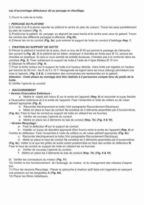
cas d’accrochage défectueux dû au perçage et chevillage.
1) Ouvrir le colis de la hotte.
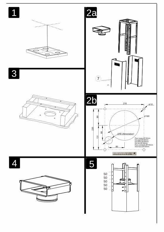
• PERCAGE DU PLAFOND2) A l’aide d’un l à plomb reporter au plafond le centre du plan de cuisson. Tracer les axes parallèlementau plan de cuisson (Fig. 1).3) Positionner le gabarit de perçage en alignant les axes tracés et le centre avec ceux du gabarit. Tracerles centres des différents perçages à effectuer. (Fig 2b)4) Enlever les vis du conduit (Fig. 2a), puis enlever le support de hotte du conduit d’habillage Rep. 7.
• FIXATION DU SUPPORT DE HOTTE5) Percer le plafond à l’endroit de la pose, dont un trou de Ø 40 qui permet le passage de l’alimenta-tion suivant la Fig. 2b. Si le plafond est en béton, employer 4 chevilles en fonte pour Ø 10, exclure les chevilles en plastique. Si celui-ci vous semble de solidité douteuse, n’hésitez pas à le renforcer dans les combles (Fig. 3). Fixer solidement le support de hotte à l’aide de 4 tiges letées Ø 10 mm.6) Déposer le diffuseur (Fig. 4).7) Fixer la boîte moteur sur le support de hotte à la hauteur désirée. Votre hotte est réglable en hauteurpar tranche de 50 mm ; les 8 vis 5 x 10 T. Hexagonale se logent dans les trous oblongs permettant une mise à l’aplomb. (Fig. 5 & 6). L’orientation des commandes est représentée sur le gabarit.Attention : Cette phase du montage doit être réalisée à 2 personnes compte tenu du poids de la hotte.8) Vérier l’aplomb du conduit.
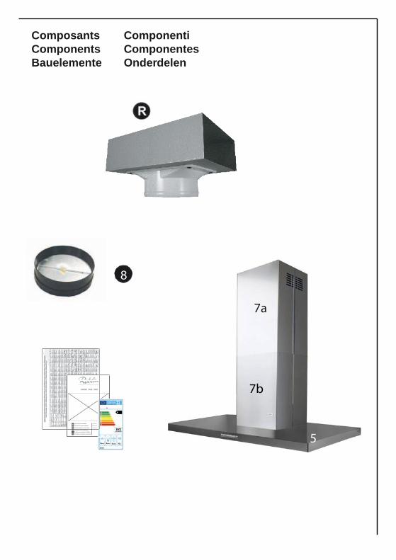
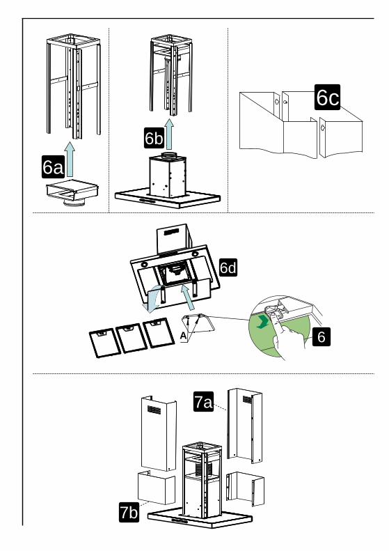
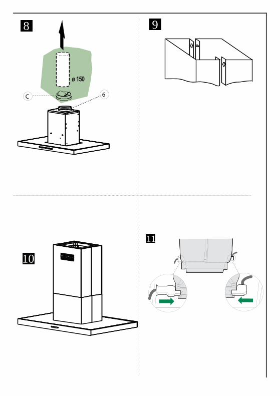
• RACCORDEMENT• Version Evacuation Extérieure : a- Mettre le clapet anti retour C sur la sortie de l’appareil (Rep. 6) et raccorder le tuyau exible à l’évacuation extérieure et à la sortie de l’appareil. Fixer l’ensemble à l’aide de colliers ou de ruban adhésif appropriés (Fig. 8). b- Raccorder électriquement la hotte (Voir paragraphe Raccordement Electrique). c- Mette en place le haut de conduit 7a constitué de 2 éléments assemblés par 6 boutonnières (Fig. 6c). Fixer le haut de conduit au support de hotte en utilisant les vis fournies. d- Vérier de nouveau l’aplomb du conduit. e- Mettre en place les 2 éléments du bas de conduit (Rep. 7b) (Fig. 9 & 10).• Version Recyclage : a- Fixer le déecteur R sur le support de conduit. b- Installer un tuyau de diamètre approprié (Non fourni) entre la sortie de l’appareil (Rep. 6) et l’entrée du déecteur. Fixer l’ensemble à l’aide de colliers ou de ruban adhésif appropriés (Fig. 6c). c- Raccorder électriquement la hotte (Voir paragraphe Raccordement Electrique). d- Mette en place le haut de conduit 7a constitué de 2 éléments assemblés par 6 boutonnières (Fig. 6c). Veiller à ce que les grilles de sortie soient positionnées en face des sorties du déecteur R. Fixer le haut de conduit au support de hotte en utilisant les vis fournies. e- Vérier de nouveau l’aplomb du conduit. f- Mettre en place les 2 éléments du bas de conduit (Rep. 7b) (Fig. 9 & 10).
9) Vérier les connecteurs du moteur (Fig. 11)10) Vérier le bon fonctionnement de l’éclairage, du moteur et du changement des vitesses d’aspira-tion.11) Pour les versions Recyclage : Placer la cartouche à charbon actif dans son logement en exerçantune pression sur les languettes A (Fig. 6d)12) Placer les ltres métalliques.
3
F
4 FONCTIONNEMENT
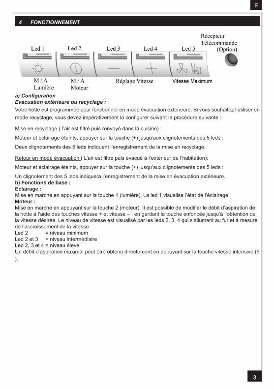
a) ConfigurationEvacuation extérieure ou recyclage :Votre hotte est programmée pour fonctionner en mode évacuation extérieure. Si vous souhaitez l’utiliser en mode recyclage, vous devez impérativement la congurer suivant la procédure suivante :
Mise en recyclage ( l’air est ltré puis renvoyé dans la cuisine) :
Moteur et éclairage éteints, appuyer sur la touche (+) jusqu’aux clignotements des 5 leds :
Deux clignotements des 5 leds indiquent l’enregistrement de la mise en recyclage.
Retour en mode évacuation ( L’air est ltré puis évacué à l’extérieur de l’habitation):
Moteur et éclairage éteints, appuyer sur la touche (+) jusqu’aux clignotements des 5 leds :
Un clignotement des 5 leds indiquera l’enregistrement de la mise en évacuation extérieure. b) Fonctions de base :Eclairage :Mise en marche en appuyant sur la touche 1 (lumière). La led 1 visualise l’état de l’éclairageMoteur :Mise en marche en appuyant sur la touche 2 (moteur). Il est possible de modier le débit d’aspiration dela hotte à l’aide des touches vitesse + et vitesse – , en gardant la touche enfoncée jusqu’à l’obtention dela vitesse désirée. Le niveau de vitesse est visualisé par les leds 2, 3, 4 qui s’allument au fur et à mesurede l’accroissement de la vitesse :Led 2 = niveau minimumLed 2 et 3 = niveau intermédiaireLed 2, 3 et 4 = niveau élevéUn débit d’aspiration maximal peut être obtenu directement en appuyant sur la touche vitesse intensive (5 ).F
4
F
• Indication de saturation des ltres métalliques :Après 200 heures de fonctionnement 1 bref clignotement de la Led 1 indique qu’il faut nettoyer lesltres métalliques (voir paragraphe entretien)Pour accéder à la remise à zéro de la fonction indiquant la saturation des ltres, la lumière doit êtreéteinte et le moteur arrêté.Appuyer sur la touche (+) pendant 3 à 4 secondes. Le clignotement des Leds 1, 2, 3, 4, et 5 conrme laremise à zéro.• Indication de saturation des ltres charbon :Après 400 heures de fonctionnement 2 brefs clignotements de la Led 1 indique qu’il faut remplacerles ltres charbon et nettoyer à nouveau les ltres métalliques.Pour activer la fonction Indication de saturation ltre charbon, la lumière doit être éteinte et le moteurarrêté. Appuyer sur la touche (+) pendant 10 secondes.1 clignotement des Leds 1, 2, 3, 4, et 5 = fonction désactivée.2 clignotements des Leds 1, 2, 3, 4, et 5 = fonction activée.La méthode de remplacement de la cartouche est indiquée au paragraphe 3 (Recyclage)
• Conguration réception télécommande :Votre hotte est programmée pour fonctionner sans réception télécommande. Si vous souhaitez l’utiliser avec la télécommande, vous devez impérativement la congurer suivant la procédure suivante : Moteur et éclairage éteints, appuyer sur la touche 1 (éclairage) jusqu’au clignotement de la led 1 : Deux clignotements de la led 1 indiquent que la télécommande est activée. Un clignotement de la led 1 indique que la télécommande est désactivée. Attention, la télécommande doit être équipée de piles alcalines standards : LR003-AAA, 1.5V comme décrit Fig. 7. Ces piles devraient assurer un usage optimum de longue durée et doivent être positionnées cor-rectement, elles peuvent exploser si elles sont endommagées ou exposées à la chaleur. Ne pas les jeter dans le feu. An de préserver l’environnement, merci de déposer ces piles dans un conteneur approprié.
5 CONSEILS D’UTILISATION
• Pour obtenir une efcacité maximum d’absorption des fumées ou des vapeurs, faire fonctionnerl’appareil 5 minutes environ avant et après la cuisson des aliments; La première vitesse est conseillée
c) Fonctions complémentaires :
pour les cuissons à feu doux et pour les sauces. La deuxième pour les cuissons soutenues, grillades etfriteuses. La troisième est indiquée pour les cuissons à forte émanation de graisses et vapeur.• IMPORTANT . NE JAMAIS FLAMBER DE METS AU DESSOUS DE L’APPAREILNe laissez jamais de ammes libres sous la hotte en fonctionnement.• Les fritures nécessitent une surveillance permanente, l’huile surchauffée pouvant s’enammer.
5
Déconnecter le câble d’alimentation pour toute intervention électrique.L’appareil a été conçu pour faciliter au maximum les opérations d’entretien, synonyme de bon fonctionne-ment et rendement de l’appareil dans le temps.• Nettoyage des ltres métalliques.Il est indispensable de procéder à un NETTOYAGE PÉRIODIQUE de ces ltres à la main (avec undétergent liquide à l’eau tiède et rinçage) ou au lave- vaisselle (tous les deux mois environ pour uneutilisation normale).• Carrosserie.Nettoyer régulièrement celle-ci en utilisant des produits détergents, non abrasifs et une éponge légère-ment humide. N’utilisez jamais d’éponges ou de chiffons trempés.N’introduisez aucun objet, ni les mains dans l’ouverture servant à l’évacuation de l’air.• Conduit d’évacuation.Vérier tous les 6 mois le bon écoulement de l’air vicié.Observer les prescriptions réglementaires locales concernant l’évacuation de l’air vicié.• Éclairage.Avant toute intervention sur l’appareil, mettre l’interrupteur d’allumage des lampes en position éteinte.Ne pas dépasser la puissance prescrite et ne pas changer de type de lampe.
7 GARANTIE ET SERVICE APRÈS-VENTE
• En cas d’anomalie de fonctionnement, prévenez votre installateur qui devra vérier l’appareil et sonraccordement.• Dans le cas où un composant électrique viendrait à être endommagé, celui-ci ne peut être remplacéque par un atelier de réparation reconnu par le fabricant, car des outils spéciaux sont nécessaires.• Débrancher complètement l’appareil.• Exigez toujours l’utilisation de pièces de rechange d’origine. La non observation de cette prescriptionpeut compromettre la sécurité de l’appareil.• Lors de la commande de pièces détachées, rappeler le numéro de l’appareil inscrit sur la plaquesignalétique située à l’intérieur de la hotte.• Seule la facture d’achat de l’appareil fera foi pour l’application de la garantie contractuelle.Cette garantie ne couvre pas les consommables comme : - L’éclairage : lampes incandescentes, halogènes ...- Les ltres.
8 REMARQUES
Cet équipement est conforme à la norme européenne sur la basse tension 2006/95/CE relative à la sécurité électrique et aux normes européennes: 2004/108/CE relative à la compatibilité électromagnéti-que et 93/68 relative au marquage CE.
Lorsque ce symbole d’une poubelle à roue barrée est attaché à un produit, cela signie que le produit est couvert par la Directive Européenne 2002/96/EC. Votre produit est conçu et fabriqué avec des matériaux et des composants de haute qualité, qui peuvent être recyclés et utilisés de nouveau. Veuillez vous informer du système local de séparation des déchets électriques et électroniques. Veuillez agir selon les règles locales et ne pas jeter vos produits usagés avec les déchets domestiques usuels. Jeter correctement votre produit usagé aidera à prévenir les conséquences négatives potentielles contre l’environnement et la santé humaine.
F
6 ENTRETIEN
9 CONSEILS POUR L’ECONOMIE D’ENERGIE.
Lorsque vous commencez à cuisiner, activer la hotte à la vitesse minimum pour contrôler l’humidité et éliminer les odeurs de cuisine.Utilisez la vitesse intensive lorsque cela est strictement nécessaire.Augmentez la vitesse de la hotte seulement lorsque la quantité de vapeur le requiert.Veillez à ce que le ou les filtres de la hotte soient toujours propres, afin d’optimiser l’éfficacité anti-graisse et anti-odeurs.
6
7
G B
Thank you for buying a Roblin product which has been manufactured to the highest quality standards tomeet your requirements.We recommend you carefully read this booklet in which you will nd instructions for installation, hints foruse and maintenance.The Instructions for Use apply to several versions of this appliance. Accordingly, you may nd descrip-tions of individual features that do not apply to your specic appliance.
1 ELECTRICAL
• This cooker hood is tted with a 3-core mains cable with a standard 10/16A earthed plug.• Alternatively the hood can be connected to the mains supply via a double-pole switch having 3mmminimum contact gap on each pole.• Before connecting to the mains supply ensure that the mains voltage corresponds to the voltage onthe rating plate inside the cooker hood.• Technical Specication: Voltage 220-240, single phase ~50/60Hz.
2 INSTALLATION ADVICE
• Ensure the cooker hood is tted in compliance with the recommended xing heights.• To ensure the safe operation of this cooker hood, we recommend that the hood should not be ttedbelow 65cm (for electric) or (70cm for gas) the measurements taken from the surface of the cookingappliance to the underside of the cooker hood.• It is a possible re risk if the hood is not sited as recommended.• To ensure the best results, the cooking fumes should be able to rise naturally towards the inlet grilleson the underside of the cooker hood and the cooker hood should be positioned away from doors andwindows, which will create turbulence.• Ducting• If the room where the hood is to be used contains a fuel-burning appliance such as a central heatingboiler then its ue must be of the room sealed or balanced ue type.• If other types of ue or appliances are tted ensure that there is an adequate supply of fresh air to theroom. Ensure the kitchen is tted with an airbrick, which should have a cross-sectional measurementequivalent to the diameter of the ducting being tted, if not larger.• The ducting system for this cooker hood must not be connected to any existing ventilation system,which is being used for any other purposes or to a mechanically controlled ventilation ducting.• The ducting used must be made from re retardant materials and the correct diameter must be used,as incorrect sized ducting will affect the performance of this cooker hood.• When the cooker hood is used in conjunction with other appliances supplied with energy other thanelectricity, the negative pressure in the room must not exceed 0.04 mbar to prevent the fumes fromcombustion being drawn back into the room.• The appliance is for domestic use only and should not be operated by children or people who areinrm without supervision.• This appliance must be positioned so that the wall socket is accessible.• This appliance is not intended for use by persons (including children) with reduced physical, sensoryor mental capabilities, or lack of experience and knowledge, unless they have been given supervision or instruction concerning use of the appliance by a person responsible for their safety.Children should be supervised to ensure that they do not play with the appliance.
3 FITTING
Any permanent electrical installation must comply with the latest regulations concerning this type ofinstallation and a qualied electrician must carry out the work. Non-compliance could cause seriousaccidents or injury and would deem the manufacturers guarantee null and void.IMPORTANT - The wires in this mains lead are coloured in accordance with the following code :
- green / yellow : earth - blue : neutral - brown : liveAs the colours of the wires in the mains lead of this appliance may not correspond with the coloured
8
G B
markings identifying the terminals in your plug, proceed as follows.- The wire which is coloured green and yellow must be connected to the terminal in the plug which ismarked with the letter E or by the earth symbol or coloured green or green and yellow.- The wire which is coloured blue must be connected to the terminal which is marked with the letter N orcoloured black.- The wire which is coloured brown must be connected to the terminal which is marked with the letter L orcoloured red.
ATTENTION: Do not forget to use adequate plugs to the support brackets. Enquire after the manu-facturers. Do an embedding if necessary. The manufacturer accepts no responsibility in case of a faulty hanging due to the drilling and the setting up of plugs.G B1) Unpack the hood parcel.
• LAYING OUT BEFORE FITTING THE HOOD2) Mark the centre of the cooking appliance onto the ceiling with a plumb line. Draw the horizontal axesrunning parallel to the stove top onto the ceiling as illustrated Fig. 1.3) Place the drill gauge centred on the axes aligning the axes on the drill gauge centrally over these axesas illustrated Fig. 2b.4) Remove the self-tapping screws, which x the chimney item 7 to the metal frame bracket as illustratedin Fig. 2a and then remove both sides of the upper chimney stacks.
• FITTING THE CANOPY BRACKET5) Mark the positions on the ceiling for : - The cut-out for the ducting Ø 150 mm in the extraction modeand Ø 200 mm in the remote mode when ducting runs through the ceiling.
- The mains supply cords. - The 4 xing holes for Ø 10 mm nuts and bolts.
Drill the different holes with the appropriate masonry bit. When xing the cooker hood to a plasterboard ceiling ensure it is reinforced as illustrated in Fig. 3 and attach using four Ø10mm nuts and bolts; ensuring the bolts as sleeved between the plasterboard and the joist supports to prevent the ceiling being damaged when the bolts are tightened up.If the ceiling is concrete, use eight Ø 10 mm steel rawl bolts. Plastic rawl plugs must not be used.6) Remove the deector Fig. 4.7) The height of the cooker hood can be adjusted in 50 mm stages. 650 mm when tting above an electrichotplate and 700 mm when tting above a gas hotplate. Select the height required using the measure-ments illustrated in Fig. 5 & 6 and x the metal diffuser to the frame of the chimney brackets using the height 5 x 10T hexagonal headed screws. A drawing on the drill gauge denes the positioning for the controls.Attention: 2 persons are necessary to secure this operation.8) Check the vertical of the chimney.
• DUCTINGThe hood is more effective when used in the extraction mode (ducted to the outside). When the cooker hood is ducted to the outside, charcoal lters are not required.The ducting used must be 150 mm (6 INS), rigid circular pipe and must be manufactured from re retard-ant material, produced to BS.476 or DIN 4102-B1. Wherever possible utilise rigid circular pipe which has a smooth interior, rather than the expanding concertina type ducting.Maximum length of ducting run: - 4 metres with 1 x 90° bend.- 3 metres with 2 x 90° bends. - 2 metres with 3 x 90° bends.The above assumes our 150 mm (6 INS) ducting is being installed. Please note ducting components and ducting kits are optional accessories and have to be ordered, they are not automatically supplied with the chimney hood.
9
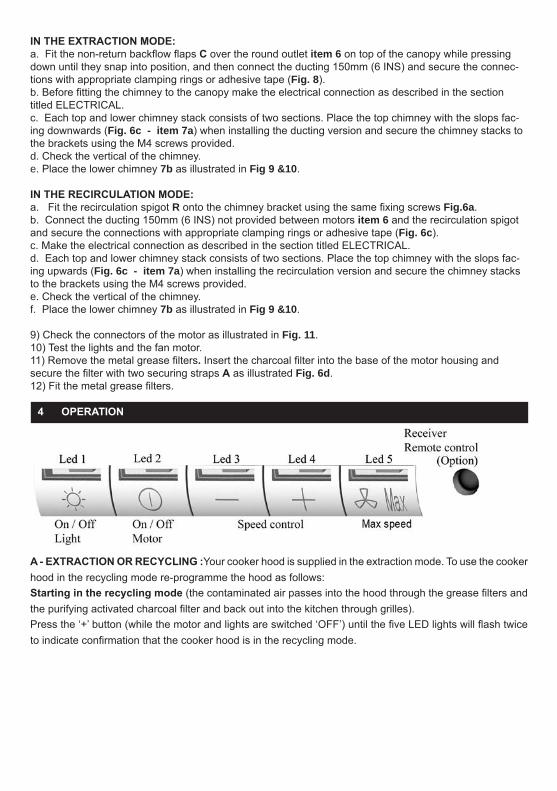
IN THE EXTRACTION MODE:a. Fit the non-return backow aps C over the round outlet item 6 on top of the canopy while pressingdown until they snap into position, and then connect the ducting 150mm (6 INS) and secure the connec-tions with appropriate clamping rings or adhesive tape (Fig. 8).b. Before tting the chimney to the canopy make the electrical connection as described in the sectiontitled ELECTRICAL.c. Each top and lower chimney stack consists of two sections. Place the top chimney with the slops fac-ing downwards (Fig. 6c - item 7a) when installing the ducting version and secure the chimney stacks to the brackets using the M4 screws provided.d. Check the vertical of the chimney.e. Place the lower chimney 7b as illustrated in Fig 9 &10.
IN THE RECIRCULATION MODE:a. Fit the recirculation spigot R onto the chimney bracket using the same xing screws Fig.6a.b. Connect the ducting 150mm (6 INS) not provided between motors item 6 and the recirculation spigotand secure the connections with appropriate clamping rings or adhesive tape (Fig. 6c).c. Make the electrical connection as described in the section titled ELECTRICAL.d. Each top and lower chimney stack consists of two sections. Place the top chimney with the slops fac-ing upwards (Fig. 6c - item 7a) when installing the recirculation version and secure the chimney stacks to the brackets using the M4 screws provided.e. Check the vertical of the chimney.f. Place the lower chimney 7b as illustrated in Fig 9 &10.
9) Check the connectors of the motor as illustrated in Fig. 11.10) Test the lights and the fan motor.11) Remove the metal grease lters. Insert the charcoal lter into the base of the motor housing andsecure the lter with two securing straps A as illustrated Fig. 6d.12) Fit the metal grease lters.
4 OPERATION
A - EXTRACTION OR RECYCLING :Your cooker hood is supplied in the extraction mode. To use the cooker hood in the recycling mode re-programme the hood as follows: Starting in the recycling mode (the contaminated air passes into the hood through the grease lters and the purifying activated charcoal lter and back out into the kitchen through grilles). Press the ‘+’ button (while the motor and lights are switched ‘OFF’) until the ve LED lights will ash twice to indicate conrmation that the cooker hood is in the recycling mode.
G B
10
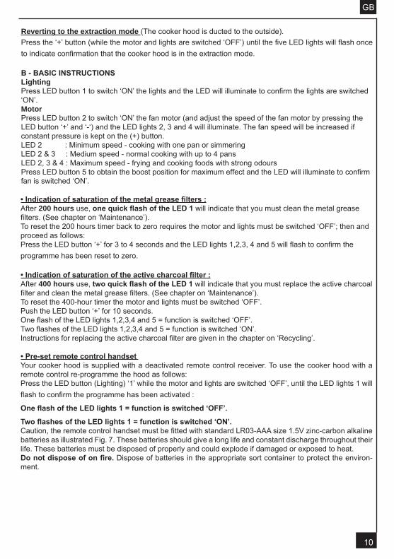
Reverting to the extraction mode (The cooker hood is ducted to the outside). Press the ‘+’ button (while the motor and lights are switched ‘OFF’) until the ve LED lights will ash once to indicate conrmation that the cooker hood is in the extraction mode. G BB - BASIC INSTRUCTIONSLightingPress LED button 1 to switch ‘ON’ the lights and the LED will illuminate to conrm the lights are switched ‘ON’.MotorPress LED button 2 to switch ‘ON’ the fan motor (and adjust the speed of the fan motor by pressing the LED button ‘+’ and ‘-‘) and the LED lights 2, 3 and 4 will illuminate. The fan speed will be increased if constant pressure is kept on the (+) button.LED 2 : Minimum speed - cooking with one pan or simmeringLED 2 & 3 : Medium speed - normal cooking with up to 4 pansLED 2, 3 & 4 : Maximum speed - frying and cooking foods with strong odoursPress LED button 5 to obtain the boost position for maximum effect and the LED will illuminate to conrm fan is switched ‘ON’.
G B
• Indication of saturation of the metal grease lters :After 200 hours use, one quick ash of the LED 1 will indicate that you must clean the metal greaselters. (See chapter on ‘Maintenance’).To reset the 200 hours timer back to zero requires the motor and lights must be switched ‘OFF’; then andproceed as follows:Press the LED button ‘+’ for 3 to 4 seconds and the LED lights 1,2,3, 4 and 5 will ash to conrm theprogramme has been reset to zero.8GB• Indication of saturation of the active charcoal lter :After 400 hours use, two quick ash of the LED 1 will indicate that you must replace the active charcoallter and clean the metal grease lters. (See chapter on ‘Maintenance’).To reset the 400-hour timer the motor and lights must be switched ‘OFF’.Push the LED button ‘+’ for 10 seconds.One ash of the LED lights 1,2,3,4 and 5 = function is switched ‘OFF’.Two ashes of the LED lights 1,2,3,4 and 5 = function is switched ‘ON’.Instructions for replacing the active charcoal lter are given in the chapter on ‘Recycling’.
• Pre-set remote control handsetYour cooker hood is supplied with a deactivated remote control receiver. To use the cooker hood with a remote control re-programme the hood as follows: Press the LED button (Lighting) ‘1’ while the motor and lights are switched ‘OFF’, until the LED lights 1 will ash to conrm the programme has been activated :
One ash of the LED lights 1 = function is switched ‘OFF’.
Two ashes of the LED lights 1 = function is switched ‘ON’. Caution, the remote control handset must be tted with standard LR03-AAA size 1.5V zinc-carbon alkaline batteries as illustrated Fig. 7. These batteries should give a long life and constant discharge throughout their life. These batteries must be disposed of properly and could explode if damaged or exposed to heat. Do not dispose of on re. Dispose of batteries in the appropriate sort container to protect the environ-ment.
11
G B
5 USEFUL HINTS
• To obtain the best performance it is advisable to switch ‘ON’ the cooker hood a few minutes (in theboost setting) before you start cooking and you should leave it running for approximately 15 minutes afternishing.• IMPORTANT: NEVER DO FLAMBÉ COOKING UNDER THIS COOKER HOOD• Do not leave frying pans unattended during use as over-heated fat and oil might catch re.• Do not leave naked ames under this cooker hood.• Switch ‘OFF’ the electric and gas before removing pots and pans.• Ensure heating areas on your hotplate are covered with pots and pans when using the hotplateand cooker hood simultaneously.
6 MAINTENANCE
Before carrying out any maintenance or cleaning isolate the cooker hood from the mains supply.The cooker hood must be kept clean; a build up of fat or grease can be a re hazard.Casing• Wipe the cooker hood frequently with a clean cloth, which has been immersed in warm water containinga mild detergent and wrung out.• Never use excessive amounts of water when cleaning particularly around the control panel.• Never use scouring pads or abrasive cleaners.• Always wear protective gloves when cleaning the cooker hood.Metal Grease FiltersThe metal grease lters absorb grease and dust during cooking to help keep the cooker hood cleaninside. The grease lters should be cleaned once a month or more frequently if the hood is used for morethan 3 hours per day.To remove and replace the metal grease lters• Remove the metal grease lters one at a time by releasing the catches on the lters; the lters cannow be removed.• The metal grease lters should be washed, by hand, in mild soapy water or in a dishwasher.• Allow to dry before replacing.Active Charcoal FilterThe charcoal lter cannot be cleaned. The lter should be replaced at least every three months or morefrequently if the hood is used for more than three hours per day.To remove and replace the lter• Remove the metal grease lters.• Press against the two retaining clips, which hold the charcoal lter in place and this will allow the lterto drop down and be removed.• Clean the surrounding area and metal grease lters as directed above.• Insert the replacement lter and ensure the two retaining clips are correctly located.• Replace the metal grease lters.Extraction tube.Check every 6 months that the dirty air is being extracted correctly. Comply with local rules and regula-tions with regard to the extraction of ventilated air.Lighting.If the lamp fails to function check to ensure it is tted correctly into the holder. If lamp failure has occurredthen it should be replaced with identical replacement.Do not replace with any other type of lamp and do not t a lamp with a higher rating.
12
G B
7 GUARANTEE AND AFTER SALES SERVICE
• In the event of any malfunction or anomaly, notify your tter who will have to check the appli-ance and its connection.• In the event of damage to the mains supply cable, this can only be replaced by at approved repaircentre appointed by the manufacturer who have the necessary tools and equipment to carry out anyrepairs properly. Repairs carried out by other persons will invalidate the guarantee.• Use only genuine spare parts. Should these warnings fail to be observed it could affect the safety ofyour cooker hood.• When ordering spare parts quote the model number and serial number written on the rating plate,which is found on the casing behind the grease lters inside the hood.• Proof of purchase will be required when requesting service. Therefore, please have your receiptavailable when requesting service as this constitutes the date from which your guarantee commenced.This Guarantee does not cover :- Damage or calls resulting from transportation, improper use or neglect, the replacement of any lightbulbs or lters or removable parts of glass or plastic.These items are considered to be consumable under the terms of this guarantee.
8 REMARKS
This appliance complies with European regulations on low voltages Directive 2006/95/CE on electrical safety, and with the following European regulations: Directive 2004/108/CE on electromagnetic compat-ibility and Directive 93/68 on EC marking.
When this crossed-out wheeled bin symbol is attached to a product it means the product is cov-ered by the European directive 2002/96/EC.Your product is designed and manufactured with high quality materials and components, which can be recycled and reused.Please inform yourself about the local separate collection system for electrical and electronic product. Please act according to your local rules and do not dispose of your old products with your normal household waste. The correct disposal of your old product will help prevent potential negative consequences for the environment and human health.
9 EN ERG Y SA V IN G TIPS.
W h e n yo u st r e m o ver .
UI n r y .K e e p r .
When you start cooking, switch on the range hood at minimum speed, to control moisture and remove cooking odor.Use boost speed only when is strictly necessary.Increase the range speed only when the amount of vapor makes it necessary.Keep range hood filter(s) clean to optimize grease and odor efficiency.
C omposantsC omponentsB auelemente
C omponentiC omponentesO nderdelen
7a
28
7b
5
XXXXXX XXXX XXXX
GB
DE
IT
GEB
NL
FR Mode d’emploi et d’installation
Instructions for use and installation
Bedienungsanleitung und einrichtung
XXX.XXXX.XXX
XXX.XXXX.XXX
XXX.XXXX.XXX
Istruzioni per l’uso e l’installazione
Instrucciones de instalacion e utilization
Instructies voor het gebruik en installeren
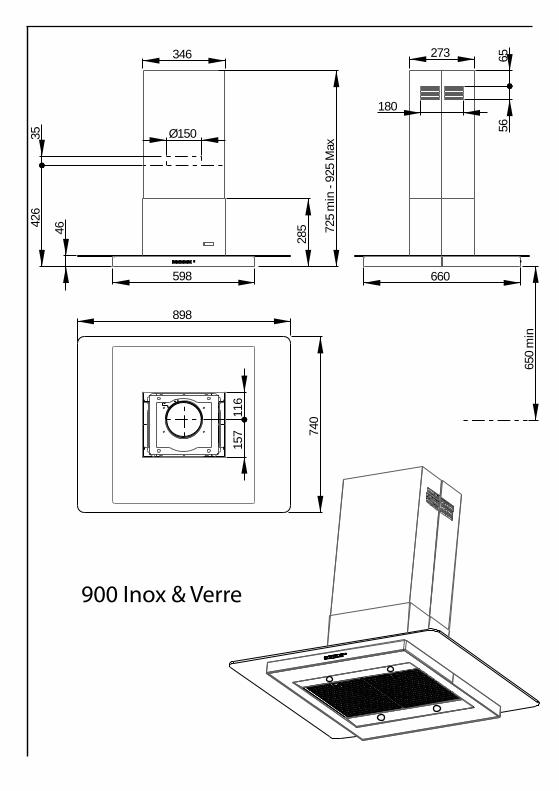
Ø150
34646 72
5 m
in -
925
Max
285
273
180
5665
89874
0
598 660
116
157
426
35
650
min
900 Inox & Verre
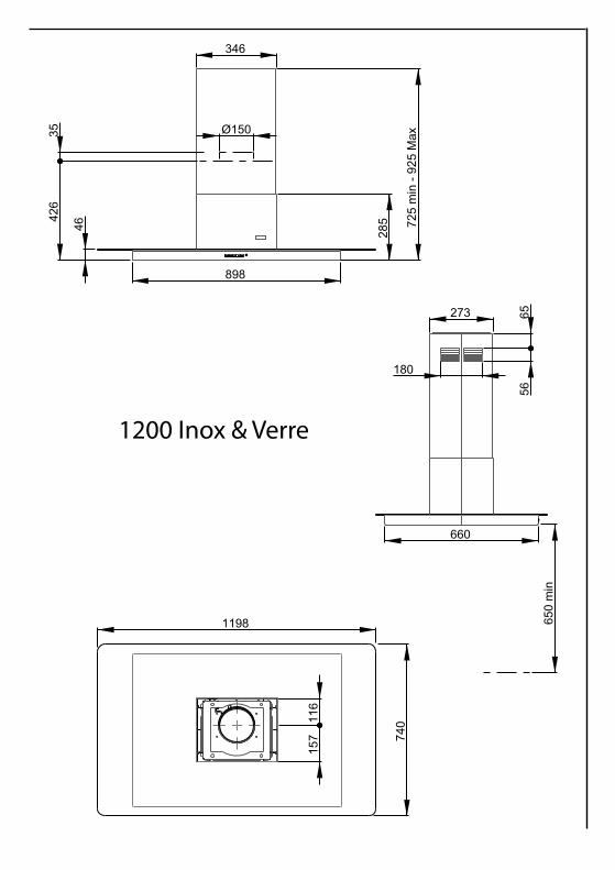
346
285
180
273
5665
116
157
725
min
- 92
5 M
ax
898
660
740
1198
35 Ø150
46
650
min
624
1200 Inox & Verre
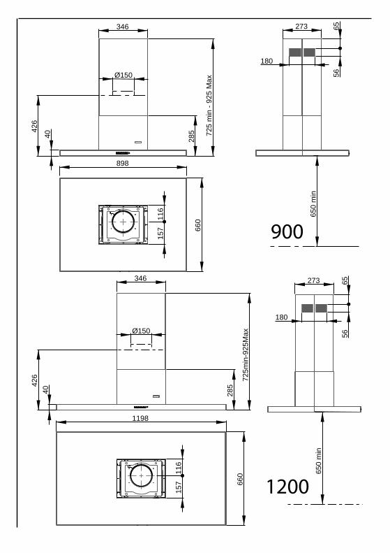
40
898
660
346
285
180
273
5665
116
157
725
min
- 92
5 M
ax
Ø150
650
min
624
346
40 285
725
min
-925
Max
273
180
6556
660
1198
Ø150
116
157
650
min
426
900
1200
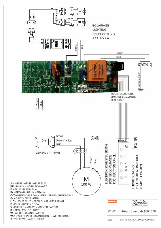
BrownBlue
L1 L2 F
N
MULTI-FLACH KABELLIMANDE COMMANDEFLAT CABLE
7 8
Brown7 8
Green-YellowBlue
MA - AZUR - AZUR - AZUR BLAUBK - BLACK - NOIR- SCHWARZB - BLUE - BLEU - BLAUBr - BROWN - BRUN - BRAUNG-Y - GREEN YELLOW - VERT JAUNE - GRÜN GELBGr - GREY - GRIS - GRAUL B - LIGHT BLUE - BLEU CLAIR - HELL BLAUP - PINK - ROSE - ROSAV - PURPLE - MAUVE - MALVER FARBIGR - RED - ROUGE - ROTW - WHITE - BLANC - WEISSW-P - WHITE PINK - BLANC ROSE - WEISS ROSA Y - YELLOW - JAUNE - GELB
100 W
01.01.2015 Atrium 3 centrale 900 1200
page 1 3S_ Atrium_3_C_90_120_150101
ECLAIRAGELIGHTINGBELEUCHTUNG4 X LEDS 1 W
PWMmotor
Blue
Blue
Yello
w
Yello
w
ELEK
TRO
NIS
CHE
STEU
ERU
NG
BOIT
IER
COM
MA
ND
EPU
SH B
UTT
ON
PA
NEL
FERN
BED
IEN
UN
GRE
CEPT
EUR
INFR
ARO
UG
ERE
MO
TE C
ON
TRO
LG
reen
-Yel
low
Red
Purple
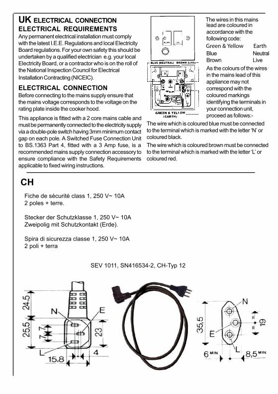
UK ELECTRICAL CONNECTIONELECTRICAL REQUIREMENTSAny permanent electrical installation must complywith the latest I.E.E. Regulations and local ElectricityBoard regulations. For your own safety this should beundertaken by a qualified electrician e.g. your localElectricity Board, or a contractor who is on the roll ofthe National Inspection Council for ElectricalInstallation Contracting (NICEIC).
ELECTRICAL CONNECTIONBefore connecting to the mains supply ensure thatthe mains voltage corresponds to the voltage on therating plate inside the cooker hood.This appliance is fitted with a 2 core mains cable andmust be permanently connected to the electricity supplyvia a double-pole switch having 3mm minimum contactgap on each pole. A Switched Fuse Connection Unitto BS.1363 Part 4, fitted with a 3 Amp fuse, is arecommended mains supply connection accessory toensure compliance with the Safety Requirementsapplicable to fixed wiring instructions.
The wires in this mainslead are coloured inaccordance with thefollowing code:
Blue NeutralBrown LiveAs the colours of the wiresin the mains lead of thisappliance may notcorrespond with thecoloured markingsidentifying the terminals inyour connection unit,proceed as follows:-
The wire which is coloured blue must be connectedto the terminal which is marked with the letter ‘N’ orcoloured black.The wire which is coloured brown must be connectedto the terminal which is marked with the letter ‘L’ orcoloured red.
CHFiche de sécurité class 1, 250 V~ 10A2 poles + terre.
Stecker der Schutzklasse 1, 250 V~ 10AZweipolig mit Schutzkontakt (Erde).
Spira di sicurezza classe 1, 250 V~ 10A2 poli + terra
SEV 1011, SN416534-2, CH-Typ 12
Green & Yellow Earth
1 2a
37
2b
4 55050505050
210
220
12
Pour tuyau Ø150mmFor pipe Ø150mmFür Rohr Ø150mmPer fori Ø150mmPara conducto Ø150mmVoor buis Ø150mm
1608913
1
40 (Alimentation)80
85
6c
6b
6a
6d
A 6
7a
7b
8 9
C 6
11
10
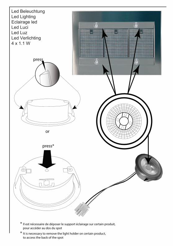
Led Beleuchtung Led Lighting Eclairage led Led Luci Led LuzLed Verlichting 4 x 1.1 W
press
or
press*
* Il est nécessaire de déposer le support éclairage sur certain produit, pour accéder au dos du spot
* It is necessary to remove the light holder on certain product, to access the back of the spot
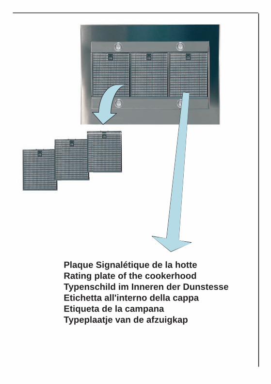
Plaque Signalétique de la hotte Rating plate of the cookerhoodTypenschild im Innere n der Dunstesse Etichetta all'interno della cappaEtiqueta de la campanaTypeplaatje van de afzuigkap
991.0347.687 - 01.01.2015
FRANKE France S.A.S. 25 Rue des Rosiers - Sainte Cécile
B. P. 60056 50800 VILLEDIEU-LES-POËLES - France
Tél. 02 33 91 26 50 - Fax 02 33 51 54 79 - e-mail : [email protected]
For outside France : Tel. +33 (0)2 33 91 26 57 - Fax. : +33 (0)2 33 51 54 79e-mail : [email protected]