Embed Size (px)
Citation preview
Conseil de l’ Europe - PACT55, 1998, pp. 213-220Revue du group européen d’ études pour les techniques physiques, chimiques, biologiques et mathematiques appliquées à l’ archaeologie
Non-destructive methods used for the estimation of the damage(weathering and cracks) of the building and ornamental stonesB. ChristarasAristotle University, School of Geology, Lab. Engineering Geology & Hydrogeology, 54006Thessaloniki, Greece, E-mail: [email protected]
Abstract:The investigation of the physical and mechanical properties of stones in monuments needs
non-destructive methods and small quantity of testing material. In this framework, P & Swaves ultrasonic velocities can be used for both in situ and laboratory measurements. Thesemethods are used for studying properties such as the mechanical anisotropy, and the modulusof elasticity of the materials. In this paper, the P-wave velocities were used for the estimationof the depth of weathered or artificially consolidated layers as well as the depth of cracks atthe surface of the building stone. This estimation was performed in relation to the lithologyand texture of the materials, given that in many cases different lithological data create similardiagrams. All tests were performed on representative monuments in Greece.
1. Introduction
Weathering effects on the physical and mechanical properties of naturalstones of monuments causing stability problems. These properties cannot beeasily studied using the common methods used for investigation in the modernconstruction, because these methods need a big quantity of testing material. So,the use of non-destructive techniques for determining the physical and mechani-cal properties of natural stones is very important because only a small quantityof testing material is needed. Methods using P & S wave velocities provide datarelated to the elasticity, anisotropy and mechanical and weathering resistance ofthe stones. Porosity, dry density, water absorption and abrasion resistance canalso tested on small specimens, providing data related to weathering and themeasured velocities.
2. Ultrasonic velocity (V, ASTM 597, ASTM D 2845- 83)
It is a good index characteristic not only for determining the physico-mechanical behaviour but also for evaluating the weathering degree of therocks. For this purpose a PUNDIT ultrasonic non-destructive digital tester is
Conseil de l’ Europe - PACT55, 1998Revue du group européen d’ études pour les techniques physiques, chimiques, biologiques et mathematiques appliquées à l’ archaeologie
214
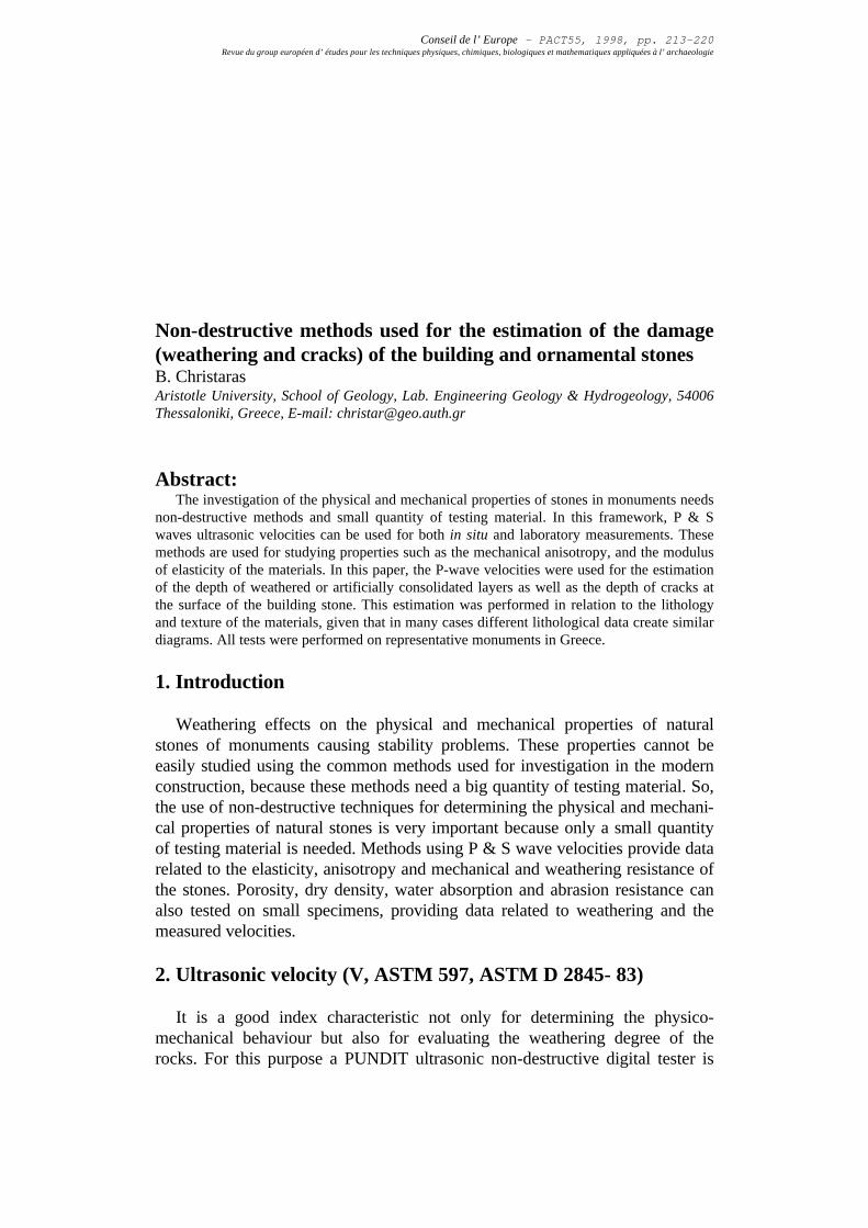
used (Fig. 1). Measurements are applied along the axis of the core samples andthe travel time of the 54-KHz source pulse was measured (for in situ measure-ments a pair of small edge transducers of 500-KHz could give more reasonableresults). Specific transducers of 300 kHz are used in the case of P and S wavevelocity measurements. Water pumpgrease, covered with a specificmembrane, is used as coupling media,to improve the acoustic contactbetween the sample and the trans-ducers. The instrument is calibratedwith aluminium standards. Thicknessand travel time corrections arecalculated by performing a linearregression between the actual and themeasured times.
Ultrasonic velocity is related to themoduli of elasticity of rocks, such asYoung's modulus and Poisson's ratio. Furthermore, it is a very good index forrock quality classification and weathering determination (Topal & Doyuran 10).
Tests are made using the direct or the indirect method, depending on thecase. The direct method is referred to the arrangement of the transducers of theapparatus on the opposite surfaces of the specimen tested. The indirect method,used especially on in-situ measurements, refers to arrangement of the transduc-ers on the same surface of the stone.
The direct transmission arrangement is the most satisfactory one since thelongitudinal pulse leaving the transmitter are propagated mainly in the directionnormal to the transducer face. In general, the pulse velocity determined by theindirect method of testing will be lower than that using the direct method. If it ispossible to employ both methods of measurement then a relationship may beestablished between them and a correction factor derived. According to themanual of the PUNDIT apparatus used, when it is not possible to use the directmethod an approximate factor of 1.05 could be used for the determination ofthe pulse velocity obtained using the direct method.
The ultrasonic velocity tests can also be used for the determination of thedynamic elastic moduli, which express the deferability of rocks. The most commonof them are the Modulus of Elasticity or Young’s Modulus (E) and the Poisson’sRatio (ν) calculated using the following formulas:
E = kdVd s2 3 4 2
2
2 2
2 2
2 2
2 2
V V
V V
V V
V Vp s
p sd
p s
p s
−−
=−−
,( )
ν
Dynamic elastic moduli are obtained by rapid application of stress to the sample.Two different dynamic methods can be used for this purpose. The first method usesP & S wave ultrasonic velocity measurements, along core specimens (Bruneau etal.2), while the second uses the excitation and detection of mechanical resonancefrequencies in small cylindrical rods and prismatic bars (Spinner & Tefft9, Glandus7).
Figure 1. The ultrasonic velocity tester. Thetransducers are placed at the opposite sitesof the specimen.
Conseil de l’ Europe - PACT55, 1998Revue du group européen d’ études pour les techniques physiques, chimiques, biologiques et mathematiques appliquées à l’ archaeologie
215
The procedure of the last method consists of exciting a specimen by means of a lightexternal mechanical impulse and of the analysis of the transient natural vibrationduring the subsequent free relaxation (Mosse8).
Test results compared statistically each other in our previous work made usingeight different lithotypes from France, determined regressions for an accurateexpression of the static elastic moduli using dynamic, non-destructive techniques(Christaras et al.3, Table 1). Typically the dynamic modulus of elasticity is greaterthan the static one, because the response of the specimen to very short durationstrain and low stress level is essentially purely elastic (Clark6).
Table 1. Relationships between dynamic and static modulus, according to theVp, Vs data (measurements on eight different rock types from France,Christaras et al.3)
X / Y RegressionCorrelation
Coef. (r)Standarddeviation
(Dynamic / Static) Elasticity Modulus Est-3.16+1.05Ed 0.994 38.02
(Dynamic / Static) Poisson's Ratio nst+0.063+0.71nd 0.737 0.057
P-wave / Static Elasticity Modulus Est=3.02e0.00055Vp 0.970 38.02
3. Surface weathering and cracks
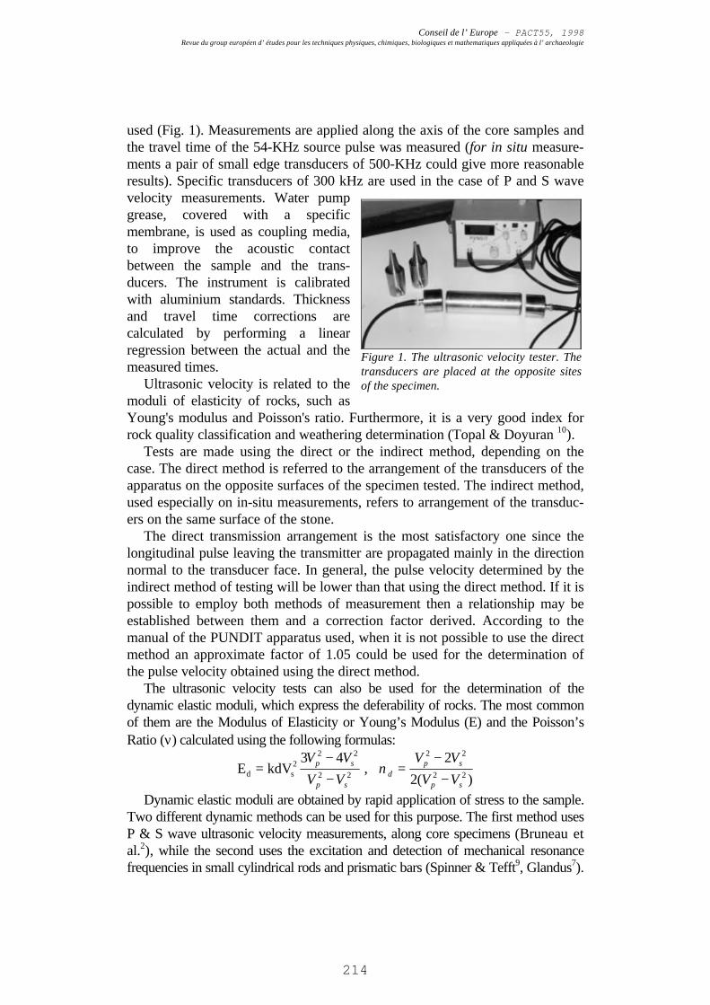
The depth of weathering at astone surface can be evaluatedusing the indirect ultrasonicvelocity technique (Christaras4,Zezza11). In this case thetransmitter is placed on a suitablepoint of the surface and thereceiver is placed on the samesurface at successive positionsalong a specific line. The transittime is plotted in relation to thedistance between the centres ofthe transducers. A change of slopein the plot could indicate that thepulse velocity near the surface ismuch lower than it is deeper downin the rock (Fig. 2). This layer ofinferior quality could arise as a result of weathering.
The thickness of the weathered surface layer is estimated as follows (Fig. 2):
D=Xo
2
Vs-Vd
Vs+Vd
Figure 2. Diagram showing the depth of thedamaged layer
Conseil de l’ Europe - PACT55, 1998Revue du group européen d’ études pour les techniques physiques, chimiques, biologiques et mathematiques appliquées à l’ archaeologie
216
Where Vs: Pulse velocity in the sound rock (Km/s)Vd: Pulse velocity in the damaged rock (Km/s)Xo: Distance at which the change of slope occurs (mm)D: depth of weathering (in mm)
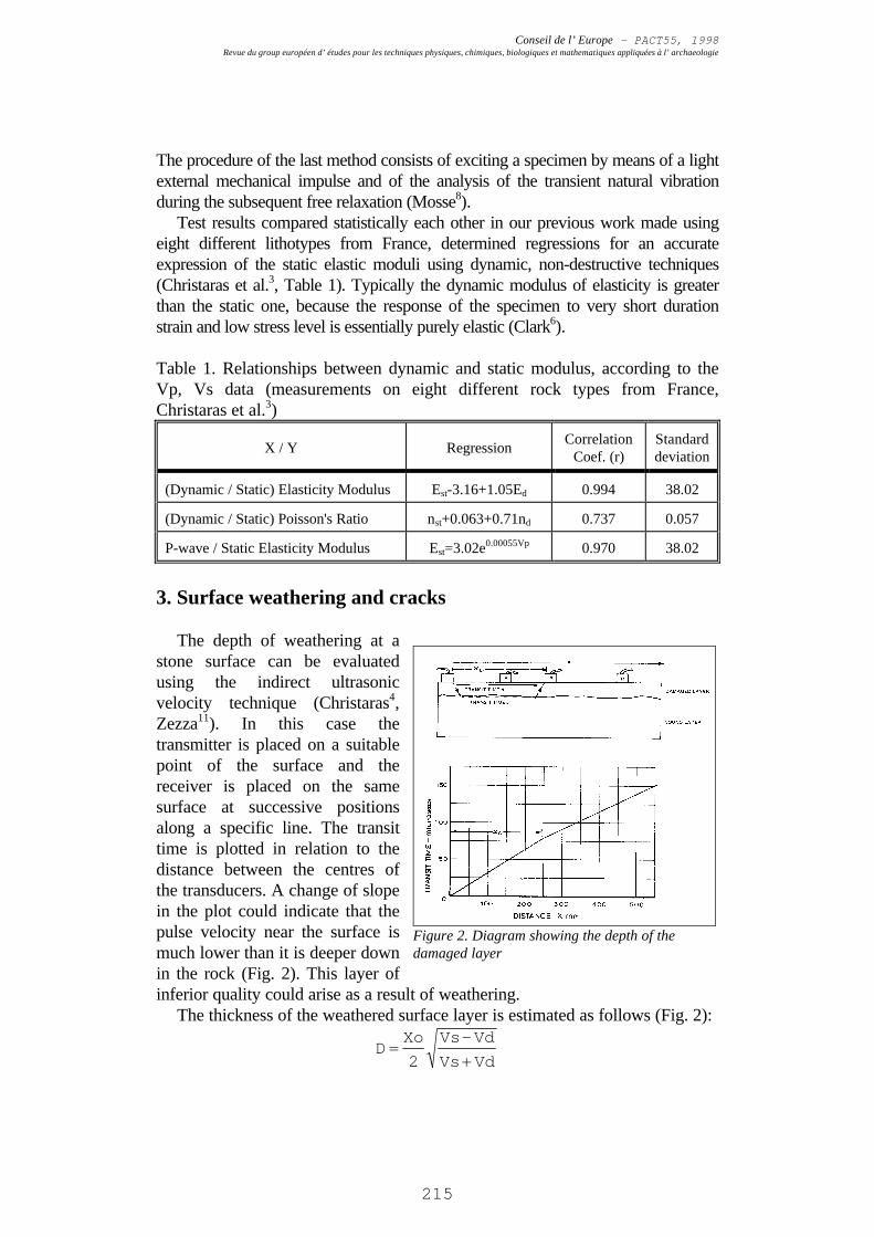
Figure 3. Estimation of the weathering depthat the surface of the marble door inAnthemion Macedonian Tomb ( see Fig. 2)
Figure 4. The marble door of the AnthemionTomb (Lefkadia Macedonian Tomb, N.Greece).
Figure 5. ultrasonic velocities measured onthe surface of travertine blocks fromLefkadia Macedonian tombs. Thedisplacement of the line corresponds to thebig pores of the materials.
Figure 6. Travertine blocks from LafkadiaMacedonian Tombs.
Two representative diagrams from the Macedonian Tomb of Anthemion (3rd
c. BC, in Naousa City of N. Greece, Alamani1, Christaras et al.5) are given inFigures 3 and 5. The first diagram corresponds to the marble of which the main
Conseil de l’ Europe - PACT55, 1998Revue du group européen d’ études pour les techniques physiques, chimiques, biologiques et mathematiques appliquées à l’ archaeologie
217
door of the tomb is constructed (Fig. 4). In this diagram the travel time of P-waves is constant in depths higher than 6.9 mm.
The second diagram (Fig. 5)corresponds to travertine, whichis the construction material of thewalls (Fig. 6). The curve, in thisdiagram, does not present thesimplicity of the previousdiagram but the pores of thestone causes parallel displace-ment of the regression line.
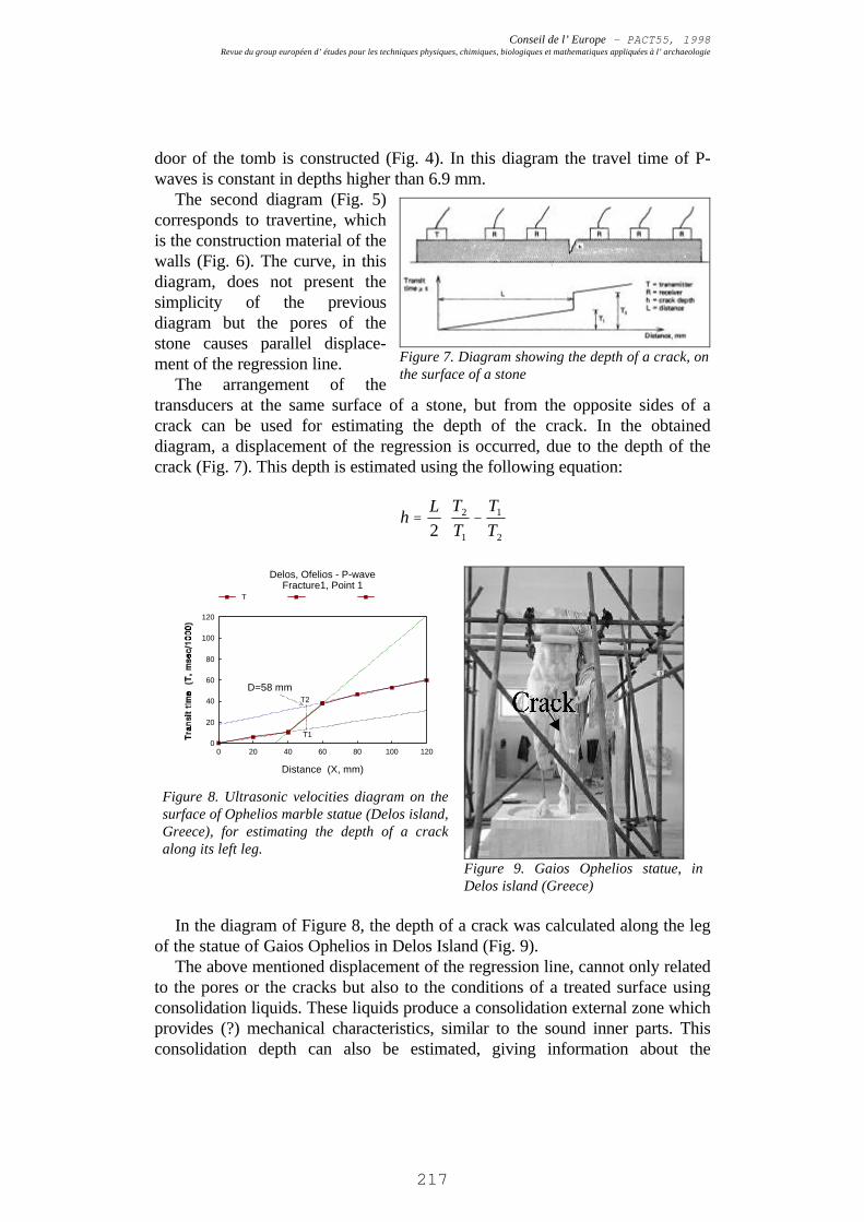
The arrangement of thetransducers at the same surface of a stone, but from the opposite sides of acrack can be used for estimating the depth of the crack. In the obtaineddiagram, a displacement of the regression is occurred, due to the depth of thecrack (Fig. 7). This depth is estimated using the following equation:
0 20 40 60 80 100 120
Distance (X, mm)
0
20
40
60
80
100
120
Delos, Ofelios - P-waveFracture1, Point 1
T
D=58 mm
T1
T2
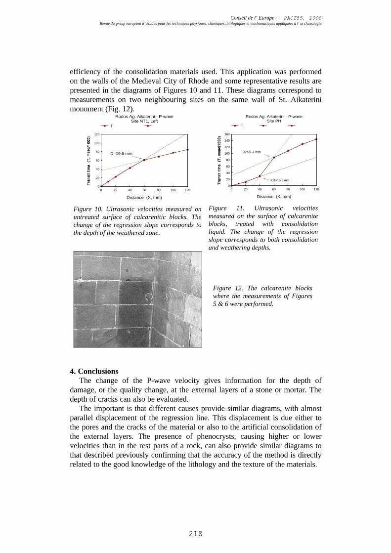
Figure 8. Ultrasonic velocities diagram on thesurface of Ophelios marble statue (Delos island,Greece), for estimating the depth of a crackalong its left leg.
Figure 9. Gaios Ophelios statue, inDelos island (Greece)
In the diagram of Figure 8, the depth of a crack was calculated along the legof the statue of Gaios Ophelios in Delos Island (Fig. 9).
The above mentioned displacement of the regression line, cannot only relatedto the pores or the cracks but also to the conditions of a treated surface usingconsolidation liquids. These liquids produce a consolidation external zone whichprovides (?) mechanical characteristics, similar to the sound inner parts. Thisconsolidation depth can also be estimated, giving information about the
Figure 7. Diagram showing the depth of a crack, onthe surface of a stone
−=
2
1
1
2
2 T
T
T
TLh
Conseil de l’ Europe - PACT55, 1998Revue du group européen d’ études pour les techniques physiques, chimiques, biologiques et mathematiques appliquées à l’ archaeologie
218
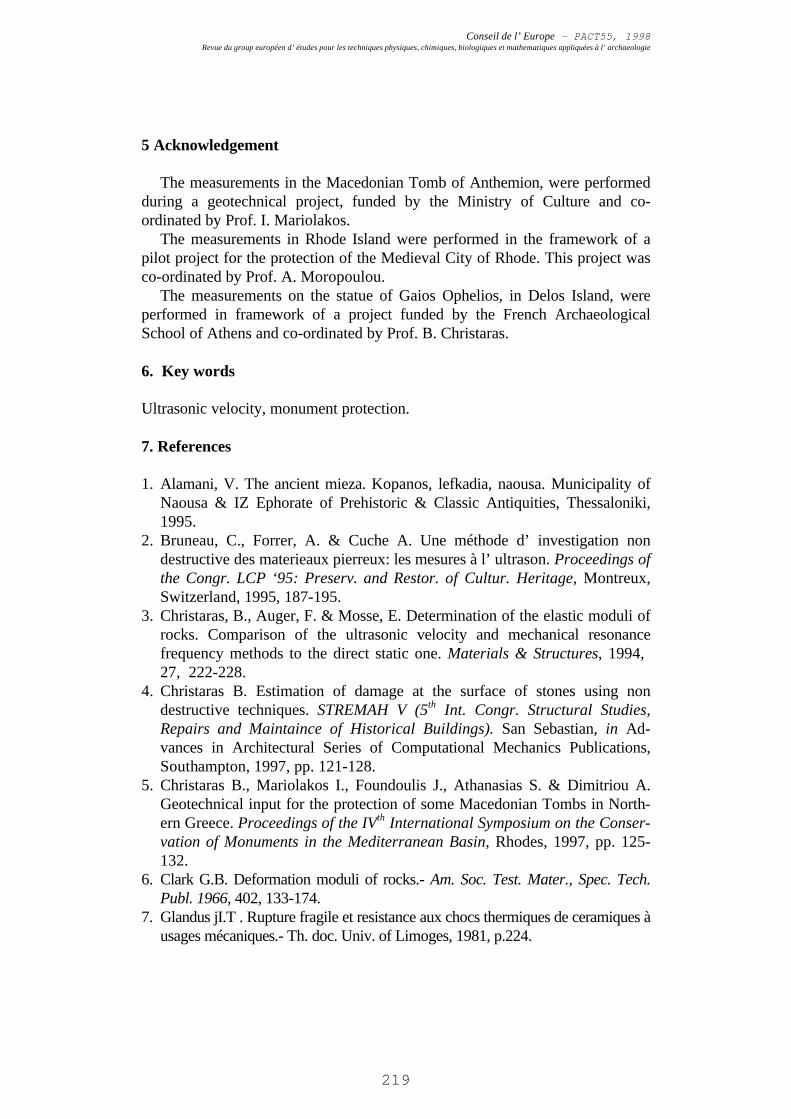
efficiency of the consolidation materials used. This application was performedon the walls of the Medieval City of Rhode and some representative results arepresented in the diagrams of Figures 10 and 11. These diagrams correspond tomeasurements on two neighbouring sites on the same wall of St. Aikaterinimonument (Fig. 12).
0 20 40 60 80 100 120
Distance (X, mm)
0
20
40
60
80
100
120
Rodos Ag. Aikaterini - P-waveSite NT1, Left
T
D=19.6 mm
Figure 10. Ultrasonic velocities measured onuntreated surface of calcarenitic blocks. Thechange of the regression slope corresponds tothe depth of the weathered zone.
0 20 40 60 80 100 120
Distance (X, mm)
0
20
40
60
80
100
120
140
160
Rodos Ag. Aikaterini - P-waveSite PH
T
D1=15.3 mm
D2=21.1 mm
Figure 11. Ultrasonic velocitiesmeasured on the surface of calcareniteblocks, treated with consolidationliquid. The change of the regressionslope corresponds to both consolidationand weathering depths.
4. ConclusionsThe change of the P-wave velocity gives information for the depth of
damage, or the quality change, at the external layers of a stone or mortar. Thedepth of cracks can also be evaluated.
The important is that different causes provide similar diagrams, with almostparallel displacement of the regression line. This displacement is due either tothe pores and the cracks of the material or also to the artificial consolidation ofthe external layers. The presence of phenocrysts, causing higher or lowervelocities than in the rest parts of a rock, can also provide similar diagrams tothat described previously confirming that the accuracy of the method is directlyrelated to the good knowledge of the lithology and the texture of the materials.
Figure 12. The calcarenite blockswhere the measurements of Figures5 & 6 were performed.
Conseil de l’ Europe - PACT55, 1998Revue du group européen d’ études pour les techniques physiques, chimiques, biologiques et mathematiques appliquées à l’ archaeologie
219
5 Acknowledgement
The measurements in the Macedonian Tomb of Anthemion, were performedduring a geotechnical project, funded by the Ministry of Culture and co-ordinated by Prof. I. Mariolakos.
The measurements in Rhode Island were performed in the framework of apilot project for the protection of the Medieval City of Rhode. This project wasco-ordinated by Prof. A. Moropoulou.
The measurements on the statue of Gaios Ophelios, in Delos Island, wereperformed in framework of a project funded by the French ArchaeologicalSchool of Athens and co-ordinated by Prof. B. Christaras.
6. Key words
Ultrasonic velocity, monument protection.
7. References
1. Alamani, V. The ancient mieza. Kopanos, lefkadia, naousa. Municipality ofNaousa & IZ Ephorate of Prehistoric & Classic Antiquities, Thessaloniki,1995.
2. Bruneau, C., Forrer, A. & Cuche A. Une méthode d’ investigation nondestructive des materieaux pierreux: les mesures à l’ ultrason. Proceedings ofthe Congr. LCP ‘95: Preserv. and Restor. of Cultur. Heritage, Montreux,Switzerland, 1995, 187-195.
3. Christaras, B., Auger, F. & Mosse, E. Determination of the elastic moduli ofrocks. Comparison of the ultrasonic velocity and mechanical resonancefrequency methods to the direct static one. Materials & Structures, 1994, 27, 222-228.
4. Christaras B. Estimation of damage at the surface of stones using nondestructive techniques. STREMAH V (5th Int. Congr. Structural Studies,Repairs and Maintaince of Historical Buildings). San Sebastian, in Ad-vances in Architectural Series of Computational Mechanics Publications,Southampton, 1997, pp. 121-128.
5. Christaras B., Mariolakos I., Foundoulis J., Athanasias S. & Dimitriou A.Geotechnical input for the protection of some Macedonian Tombs in North-ern Greece. Proceedings of the IVth International Symposium on the Conser-vation of Monuments in the Mediterranean Basin, Rhodes, 1997, pp. 125-132.
6. Clark G.B. Deformation moduli of rocks.- Am. Soc. Test. Mater., Spec. Tech.Publ. 1966, 402, 133-174.
7. Glandus jI.T . Rupture fragile et resistance aux chocs thermiques de ceramiques àusages mécaniques.- Th. doc. Univ. of Limoges, 1981, p.224.
Conseil de l’ Europe - PACT55, 1998Revue du group européen d’ études pour les techniques physiques, chimiques, biologiques et mathematiques appliquées à l’ archaeologie
220
8. Mosse E. Relations entre vitesse du son, module d' elasticité et coefficient dePoisson, mesurés par des méthodes statiques et dynamiques. application auxmatériaux pierreux.- D.E.A., Univesr. Poitiers, La Rochelle, 1990, 1-100.
9. Spinner S. & Tefft W.E.. A method for determining mechanical resonancefrequencies and for calculating elastic moduli from these frequencies.- Proceed-ings of the A.S.T.M., 61, 1961, 1229-1238.
10. Topal, T. & Doyuran V. Ultrasonic testing of artificially weatheredcappadocian tuff. Proceedings of the Congr. LCP ‘95: Preserv. and Restor.of Cultur. Heritage, Montreux, Switzerland, 1995, 205-213.
11. Zezza, F. Evaluation criteria of the effectiveness of treatments by nondestructive analysis. Proceedings of the 2nd Course of CUN UniversitySchool of Monument Concervation, Heraklion, 1993, 198-207.


![Study of Information Extraction in Resume · ALEX Resume parsing [1], ResumeGrabber Suite and Daxtra CVX [7]. There are four types of methods used in resume information extraction:](https://img.pdfslide.fr/doc/110x75/5edae1f909ac2c67fa68764c/study-of-information-extraction-in-resume-alex-resume-parsing-1-resumegrabber.jpg)