Embed Size (px)
Citation preview
Compact microwave cavity for high performance rubidiumfrequency standardsCamillo Stefanucci,1,a) Thejesh Bandi,2,a) Francesco Merli,1 Matthieu Pellaton,2
Christoph Affolderbach,2 Gaetano Mileti,2 and Anja K. Skrivervik1
1Laboratoire d’Électromagnétisme et d’Acoustique (LEMA), École Polytechnique Fédérale de Lausanne,CH-1015 Lausanne, Switzerland2Laboratoire Temps-Fréquence (LTF), Institut de Physique, Université de Neuchâtel,CH-2000 Neuchâtel, Switzerland
The design, realization, and characterization of a compact magnetron-type microwave cavity operat-ing with a TE011-like mode are presented. The resonator works at the rubidium hyperfine ground-statefrequency (i.e., 6.835 GHz) by accommodating a glass cell of 25 mm diameter containing rubid-ium vapor. Its design analysis demonstrates the limitation of the loop-gap resonator lumped modelwhen targeting such a large cell, thus numerical optimization was done to obtain the required per-formances. Microwave characterization of the realized prototype confirmed the expected workingbehavior. Double-resonance and Zeeman spectroscopy performed with this cavity indicated an excel-lent microwave magnetic field homogeneity: the performance validation of the cavity was done byachieving an excellent short-term clock stability as low as 2.4 × 10⁻¹³ τ−1/2. The achieved experi-mental results and the compact design make this resonator suitable for applications in portable atomichigh-performance frequency standards for both terrestrial and space applications.
I. INTRODUCTION
Rubidium (Rb) atomic clocks1, 2 are used as secondaryfrequency standards. Their compactness and competitivestability—over one to several days—make them interestingand suitable candidates for satellite navigation and telecom-munication systems applications.3
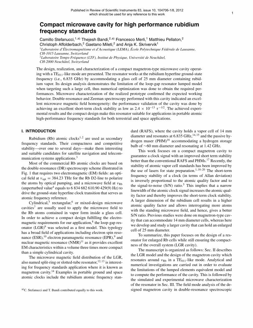
Most of the commercial Rb atomic clocks are based onthe double-resonance (DR) spectroscopy scheme illustrated inFig. 1 that requires two electromagnetic (EM) fields: an opti-cal field at νopt = 384.23 THz for the Rb D2-line to polarizethe atoms by optical pumping, and a microwave field at νRb
(unperturbed value4 equals to 6 834 682 610.90 429(9) Hz) todrive the ground-state hyperfine clock transition that serves asatomic frequency reference.
Cylindrical,5 rectangular,6 or mixed-design microwavecavities7 are usually used to apply the microwave field tothe Rb atoms contained in vapor form inside a glass cell.In order to achieve a compact design fulfilling the electro-magnetic requirements for our application,8 the loop-gap res-onator (LGR)9 was selected as a first model. This typologyhas a broad field of applications including electron spin reso-nance (ESR),10 electron paramagnetic resonance (EPR),9 andnuclear magnetic resonance (NMR)11 as it provides excellentEM characteristics within a volume three times more compactthan a simple cylindrical cavity.
The microwave magnetic field distribution of the LGR,also named split-ring or slotted-tube resonator,12, 13 is interest-ing for frequency standards application where it is known asmagnetron cavity.14 Examples in portable ground and spaceatomic clocks include the rubidium atomic frequency stan-
a)C. Stefanucci and T. Bandi contributed equally to this work.
dard (RAFS), where the cavity holds a vapor cell of 14 mmdiameter and resonates at 6.835 GHz,14, 15 and the passive hy-drogen maser (PHM)16 accommodating a hydrogen storagebulb of ∼60 mm diameter and resonating at 1.42 GHz.
This work focuses on a compact magnetron cavity toguarantee a clock signal with an improved short term stabilitybetter than the conventional RAFS and PHMs.17 Recently, thestability of atomic vapor cell standards has been improved bythe use of lasers for state preparation.1, 18–20 The short-termfrequency stability of a clock (in terms of Allan deviation)is inversely proportional to the atomic quality factor and tothe signal-to-noise (S/N) ratio.5 This implies that a narrowlinewidth of the atomic clock signal increases the atomic qual-ity factor and thereby improves the short-term clock stability.A larger dimension of the rubidium cell results in a higheratomic quality factor and allows interrogating more atomswith the standing microwave field, and hence, gives a betterS/N ratio. Previous studies were done on magnetron-type cav-ity that can accommodate 14 mm diameter cells, whereas herewe develop and study a larger cavity that can hold an enlargedcell of 25 mm diameter.
To summarize, this paper focuses on the design of a res-onator for enlarged Rb cells while still ensuring the compact-ness of the overall system (LGR cavity).
The manuscript is organized as follows: Sec. II describesthe LGR model and the design of the magnetron cavity whichresonates around νRb in a TE011-like mode. Analytical andnumerical investigations are carried out in order to evaluatethe limitations of the lumped elements equivalent model andto compute the performance of the cavity. This is followed bythe simulated and experimental microwave characterizationof the resonator in Sec. III. The field mode analysis of the de-signed magnetron cavity in double-resonance spectroscopic
Published in Review of Scientific Instruments 83, issue 10, 104706-1/8, 2012 which should be used for any reference to this work 1
Rb Atoms
Laser (ν )
Microwave excitation (ν ) Photodetector
Phot
ocur
rent
ν Rb ν
z
C-field coil
Rb
opt
FIG. 1. DR spectroscopy principle: Rb atoms inside a cell are excited by alaser beam at νopt and an EM field at νRb. The clock frequency is determinedby a photodetector. The C-field is a dc magnetic field to separate the hyperfineenergy levels by Zeeman splitting5 and it identifies the quantization axis1
(it coincides with the z-axis).
experiments is presented in Sec. IV. Finally, Sec. V validatesthe cavity by demonstrating the frequency stability of ourclock, while conclusions are drawn in Sec. VI.
II. MICROWAVE CAVITY DESIGN
A. Loop-gap resonator model
The LGR consists in a metallic slotted loop inside a cylin-drical shield. The simplicity of the structure allows the use ofa lumped elements equivalent model to estimate the resonancefrequency10, 21 νr,
νr = 1
2π
√n
πr2εμ
t
w︸ ︷︷ ︸LC
√1 + r2
R2 − (r + w)2︸ ︷︷ ︸shield
√1
1 + 2.5 tw︸ ︷︷ ︸
fringing
,
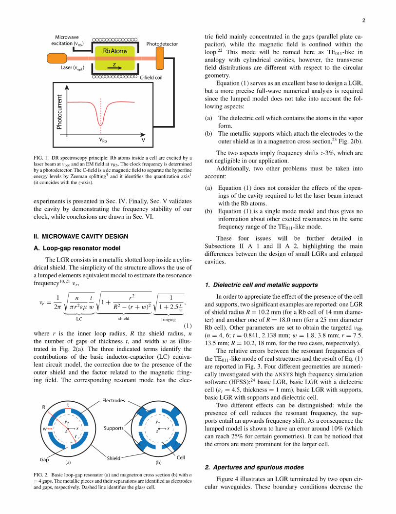
(1)where r is the inner loop radius, R the shield radius, nthe number of gaps of thickness t, and width w as illus-trated in Fig. 2(a). The three indicated terms identify thecontributions of the basic inductor-capacitor (LC) equiva-lent circuit model, the correction due to the presence of theouter shield and the factor related to the magnetic fring-ing field. The corresponding resonant mode has the elec-
Electrodes
Shield
Supports x
y
zx
y
z
Gap
w
t
r
R
Cell
FIG. 2. Basic loop-gap resonator (a) and magnetron cross section (b) with n= 4 gaps. The metallic pieces and their separations are identified as electrodesand gaps, respectively. Dashed line identifies the glass cell.
tric field mainly concentrated in the gaps (parallel plate ca-pacitor), while the magnetic field is confined within theloop.22 This mode will be named here as TE011-like inanalogy with cylindrical cavities, however, the transversefield distributions are different with respect to the circulargeometry.
Equation (1) serves as an excellent base to design a LGR,but a more precise full-wave numerical analysis is requiredsince the lumped model does not take into account the fol-lowing aspects:
(a) The dielectric cell which contains the atoms in the vaporform.
(b) The metallic supports which attach the electrodes to theouter shield as in a magnetron cross section,23 Fig. 2(b).
The two aspects imply frequency shifts >3%, which arenot negligible in our application.
Additionally, two other problems must be taken intoaccount:
(a) Equation (1) does not consider the effects of the open-ings of the cavity required to let the laser beam interactwith the Rb atoms.
(b) Equation (1) is a single mode model and thus gives noinformation about other excited resonances in the samefrequency range of the TE011-like mode.
These four issues will be further detailed inSubsections II A 1 and II A 2, highlighting the maindifferences between the design of small LGRs and enlargedcavities.
1. Dielectric cell and metallic supports
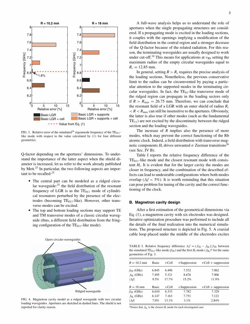
In order to appreciate the effect of the presence of the celland supports, two significant examples are reported: one LGRof shield radius R = 10.2 mm (for a Rb cell of 14 mm diame-ter) and another one of R = 18.0 mm (for a 25 mm diameterRb cell). Other parameters are set to obtain the targeted νRb
(n = 4, 6; t = 0.841, 2.138 mm; w = 1.8, 3.8 mm; r = 7.5,13.5 mm; R = 10.2, 18 mm, for the two cases, respectively).
The relative errors between the resonant frequencies ofthe TE011-like mode of real structures and the result of Eq. (1)are reported in Fig. 3. Four different geometries are numeri-cally investigated with the ANSYS high frequency simulationsoftware (HFSS):24 basic LGR, basic LGR with a dielectriccell (εr = 4.5, thickness = 1 mm), basic LGR with supports,basic LGR with supports and dielectric cell.
Two different effects can be distinguished: while thepresence of cell reduces the resonant frequency, the sup-ports entail an upwards frequency shift. As a consequence thelumped model is shown to have an error around 10% (whichcan reach 25% for certain geometries). It can be noticed thatthe errors are more prominent for the larger cell.
2. Apertures and spurious modes
Figure 4 illustrates an LGR terminated by two open cir-cular waveguides. These boundary conditions decrease the
2
Basic LGR Basic LGR + cell
Basic LGR + supportsBasic LGR + supports + cell
Value from Eq. (1)
0 5 10 156
6.2
6.4
6.6
6.8
7
7.2
7.4
7.6
7.8
8R = 18 mm
Relative error [%]
Fre
qu
en
cy [
GH
z]
0 5 10 156
6.2
6.4
6.6
6.8
7
7.2
7.4
7.6
7.8
8R = 10.2 mm
Relative error [%]
Fre
qu
en
cy [
GH
z]
1.6%
FIG. 3. Relative error of the simulated24 eigenmode frequency of the TE011-like mode with respect to the value calculated by (1) for four differentgeometries.
Q-factor depending on the apertures’ dimensions. To under-stand the importance of the latter aspect when the shield di-ameter is increased, let us refer to the work already publishedby Mett.25 In particular, the two following aspects are impor-tant to be recalled:25
� The central part can be modeled as a ridged circu-lar waveguide:25 the field distribution of the resonantfrequency of LGR is as the TE011 mode of cylindri-cal resonators perturbed by the presence of the elec-trodes (becoming TE011-like). However, other trans-verse modes can be excited.
� The top and bottom loading sections may support TEand TM transverse modes of a classic circular waveg-uide (thus, a different field distribution from the fring-ing configuration of the TE011-like mode).
FIG. 4. Magnetron cavity model as a ridged waveguide with two circularloading waveguides. Apertures are sketched in dashed lines. The shield is notreported for clarity reason.
A full-wave analysis helps us to understand the role ofapertures when the single propagating structures are consid-ered. If a propagating mode is excited in the loading sections,it couples with the openings implying a modification of thefield distribution in the central region and a stronger decreaseof the Q-factor because of the related radiation. For this rea-son, the terminating waveguides are usually designed to workunder cut-off.10 This means for applications at νRb setting themaximum radius of the empty circular waveguides equal toRc = 12.85 mm.
In general, setting R > Rc requires the precise analysis ofthe loading sections. Nonetheless, the previous conservativelimit to the radius can be circumvented by paying a partic-ular attention to the supported modes in the terminating cir-cular waveguides. In fact, the TE01-like transverse mode ofthe ridged region can propagate in the loading sectors onlyif R > Rmax = 26.75 mm. Therefore, we can conclude thatthe resonant field of a LGR with an outer shield of radius Rc
< R < Rmax can still be insensitive to the apertures. Obviously,the latter is also true if other modes (such as the fundamentalTE11) are not excited by the discontinuity between the ridgedsection and the loading waveguides.
The increase of R implies also the presence of moremodes, which may prevent the correct functioning of the Rbatomic clock. Indeed, a field distribution with transverse mag-netic components Ht drives unwanted σ Zeeman transitions26
(see Sec. IV B).Table I reports the relative frequency difference of the
TE011-like mode and the closest resonant mode with consis-tent Ht. It is evident that for the larger cavity the modes arecloser in frequency, and the combination of the described ef-fects can lead to undesirable configurations where both modesoverlap (�f < 5%). It is worth reminding that this situationcan pose problem for tuning of the cavity and the correct func-tioning of the clock.
B. Magnetron cavity design
After a first estimation of the geometrical dimensions viaEq. (1), a magnetron cavity with six electrodes was designed.Iterative optimization procedure was performed to include allthe details of the final realization into the numerical simula-tions. The proposed structure is depicted in Fig. 5. A coaxialcable loop placed under the middle of the electrodes excites
TABLE I. Relative frequency difference �f = (fTE − fHt )/fTE betweenthe simulated TE011-like mode (fTE) and the first Ht mode (fHt )
a for the samegeometries of Fig. 3.
R = 10.2 mm Basic +Cell +Suppression +Cell + suppression
fTE (GHz) 6.845 6.496 7.532 7.062fHt (GHz) 7.495 5.321 8.676 7.906|�f| 9.5% 17.7% 15.2% 11.9%
R = 18 mm Basic +Cell +Suppression +Cell + suppressionfTE (GHz) 6.610 6.333 7.782 7.329fHt (GHz) 6.147 7.163 7.751 7.121|�f| 7.0% 13.1% 3.1% 2.84%
aNotice that fHt is the closest Ht mode for each investigated case.
3
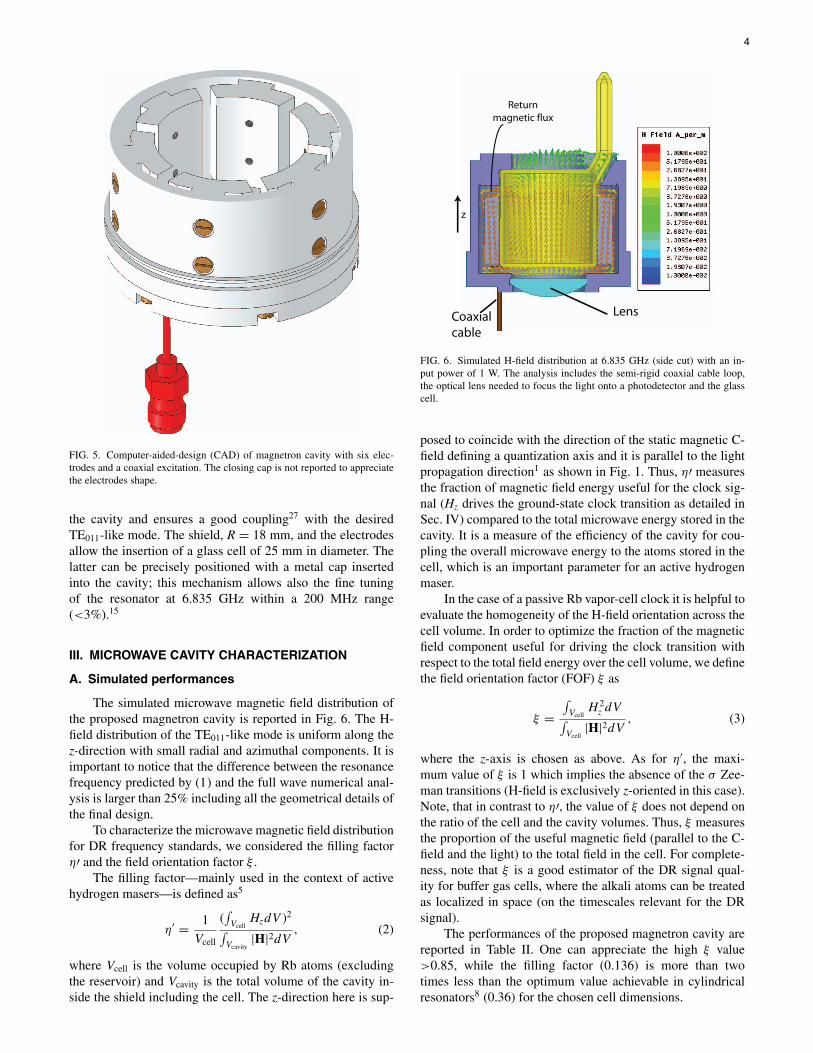
FIG. 5. Computer-aided-design (CAD) of magnetron cavity with six elec-trodes and a coaxial excitation. The closing cap is not reported to appreciatethe electrodes shape.
the cavity and ensures a good coupling27 with the desiredTE011-like mode. The shield, R = 18 mm, and the electrodesallow the insertion of a glass cell of 25 mm in diameter. Thelatter can be precisely positioned with a metal cap insertedinto the cavity; this mechanism allows also the fine tuningof the resonator at 6.835 GHz within a 200 MHz range(<3%).15
III. MICROWAVE CAVITY CHARACTERIZATION
A. Simulated performances
The simulated microwave magnetic field distribution ofthe proposed magnetron cavity is reported in Fig. 6. The H-field distribution of the TE011-like mode is uniform along thez-direction with small radial and azimuthal components. It isimportant to notice that the difference between the resonancefrequency predicted by (1) and the full wave numerical anal-ysis is larger than 25% including all the geometrical details ofthe final design.
To characterize the microwave magnetic field distributionfor DR frequency standards, we considered the filling factorη′ and the field orientation factor ξ .
The filling factor—mainly used in the context of activehydrogen masers—is defined as5
η′ = 1
Vcell
(∫Vcell
HzdV )2∫Vcavity
|H|2dV, (2)
where Vcell is the volume occupied by Rb atoms (excludingthe reservoir) and Vcavity is the total volume of the cavity in-side the shield including the cell. The z-direction here is sup-
LensCoaxialcable
Return magnetic flux
z
FIG. 6. Simulated H-field distribution at 6.835 GHz (side cut) with an in-put power of 1 W. The analysis includes the semi-rigid coaxial cable loop,the optical lens needed to focus the light onto a photodetector and the glasscell.
posed to coincide with the direction of the static magnetic C-field defining a quantization axis and it is parallel to the lightpropagation direction1 as shown in Fig. 1. Thus, η′ measuresthe fraction of magnetic field energy useful for the clock sig-nal (Hz drives the ground-state clock transition as detailed inSec. IV) compared to the total microwave energy stored in thecavity. It is a measure of the efficiency of the cavity for cou-pling the overall microwave energy to the atoms stored in thecell, which is an important parameter for an active hydrogenmaser.
In the case of a passive Rb vapor-cell clock it is helpful toevaluate the homogeneity of the H-field orientation across thecell volume. In order to optimize the fraction of the magneticfield component useful for driving the clock transition withrespect to the total field energy over the cell volume, we definethe field orientation factor (FOF) ξ as
ξ =∫Vcell
H 2z dV∫
Vcell|H|2dV
, (3)
where the z-axis is chosen as above. As for η′, the maxi-mum value of ξ is 1 which implies the absence of the σ Zee-man transitions (H-field is exclusively z-oriented in this case).Note, that in contrast to η′, the value of ξ does not depend onthe ratio of the cell and the cavity volumes. Thus, ξ measuresthe proportion of the useful magnetic field (parallel to the C-field and the light) to the total field in the cell. For complete-ness, note that ξ is a good estimator of the DR signal qual-ity for buffer gas cells, where the alkali atoms can be treatedas localized in space (on the timescales relevant for the DRsignal).
The performances of the proposed magnetron cavity arereported in Table II. One can appreciate the high ξ value>0.85, while the filling factor (0.136) is more than twotimes less than the optimum value achievable in cylindricalresonators8 (0.36) for the chosen cell dimensions.
4
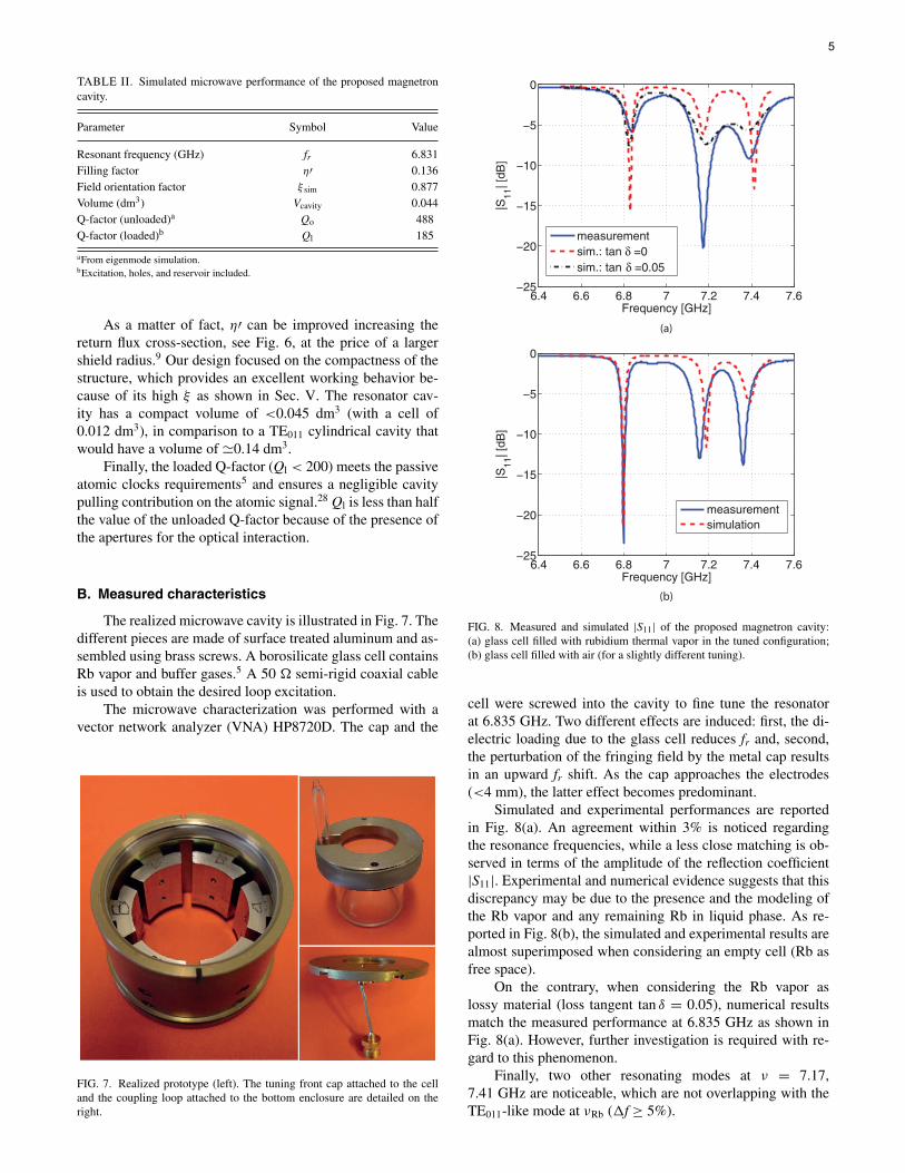
TABLE II. Simulated microwave performance of the proposed magnetroncavity.
Parameter Symbol Value
Resonant frequency (GHz) fr 6.831Filling factor η′ 0.136Field orientation factor ξ sim 0.877Volume (dm3) Vcavity 0.044Q-factor (unloaded)a Qo 488Q-factor (loaded)b Ql 185
aFrom eigenmode simulation.bExcitation, holes, and reservoir included.
As a matter of fact, η′ can be improved increasing thereturn flux cross-section, see Fig. 6, at the price of a largershield radius.9 Our design focused on the compactness of thestructure, which provides an excellent working behavior be-cause of its high ξ as shown in Sec. V. The resonator cav-ity has a compact volume of <0.045 dm3 (with a cell of0.012 dm3), in comparison to a TE011 cylindrical cavity thatwould have a volume of �0.14 dm3.
Finally, the loaded Q-factor (Ql < 200) meets the passiveatomic clocks requirements5 and ensures a negligible cavitypulling contribution on the atomic signal.28 Ql is less than halfthe value of the unloaded Q-factor because of the presence ofthe apertures for the optical interaction.
B. Measured characteristics
The realized microwave cavity is illustrated in Fig. 7. Thedifferent pieces are made of surface treated aluminum and as-sembled using brass screws. A borosilicate glass cell containsRb vapor and buffer gases.5 A 50 semi-rigid coaxial cableis used to obtain the desired loop excitation.
The microwave characterization was performed with avector network analyzer (VNA) HP8720D. The cap and the
FIG. 7. Realized prototype (left). The tuning front cap attached to the celland the coupling loop attached to the bottom enclosure are detailed on theright.
6.4 6.6 6.8 7 7.2 7.4 7.6−25
−20
−15
−10
−5
0
Frequency [GHz]
|S11
| [dB
]
measurementsim.: tan δ =0sim.: tan δ =0.05
6.4 6.6 6.8 7 7.2 7.4 7.6−25
−20
−15
−10
−5
0
Frequency [GHz]
|S11
| [dB
]
measurementsimulation
(a)
(b)
FIG. 8. Measured and simulated |S11| of the proposed magnetron cavity:(a) glass cell filled with rubidium thermal vapor in the tuned configuration;(b) glass cell filled with air (for a slightly different tuning).
cell were screwed into the cavity to fine tune the resonatorat 6.835 GHz. Two different effects are induced: first, the di-electric loading due to the glass cell reduces fr and, second,the perturbation of the fringing field by the metal cap resultsin an upward fr shift. As the cap approaches the electrodes(<4 mm), the latter effect becomes predominant.
Simulated and experimental performances are reportedin Fig. 8(a). An agreement within 3% is noticed regardingthe resonance frequencies, while a less close matching is ob-served in terms of the amplitude of the reflection coefficient|S11|. Experimental and numerical evidence suggests that thisdiscrepancy may be due to the presence and the modeling ofthe Rb vapor and any remaining Rb in liquid phase. As re-ported in Fig. 8(b), the simulated and experimental results arealmost superimposed when considering an empty cell (Rb asfree space).
On the contrary, when considering the Rb vapor aslossy material (loss tangent tan δ = 0.05), numerical resultsmatch the measured performance at 6.835 GHz as shown inFig. 8(a). However, further investigation is required with re-gard to this phenomenon.
Finally, two other resonating modes at ν = 7.17,7.41 GHz are noticeable, which are not overlapping with theTE011-like mode at νRb (�f ≥ 5%).
5
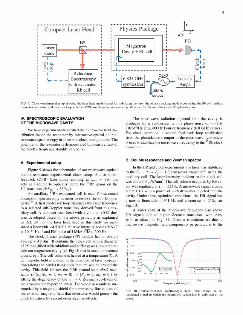
FIG. 9. Clock experimental setup showing the laser head module used for stabilizing the laser, the physics package module containing the Rb cell inside amagnetron resonator, and the clock loop with the OCXO oscillator and microwave synthesizer. (BS) Beam splitter and (PD) photodetector.
IV. SPECTROSCOPIC EVALUATIONOF THE MICROWAVE CAVITY
We have experimentally verified the microwave field dis-tribution inside the resonator by microwave-optical double-resonance spectroscopy in an atomic clock configuration. Thepotential of the resonator is demonstrated by measurement ofthe clock’s frequency stability in Sec. V.
A. Experimental setup
Figure 9 shows the schematics of our microwave-opticaldouble-resonance experimental clock setup. A distributed-feedback (DFB) laser diode emitting at λopt = 780 nmacts as a source to optically pump the 87Rb atoms on theD2-transition (52S1/2 → 52P3/2).
An auxiliary 87Rb evacuated cell is used for saturatedabsorption spectroscopy in order to resolve the sub-Dopplerpeaks.29 A first feed-back loop stabilizes the laser frequencyto a selected sub-Doppler transition, derived from this aux-iliary cell. A compact laser head with a volume <0.87 dm3
was developed based on the above principle as explainedin Ref. 29. For the laser head used in this study we mea-sured a linewidth <4.5 MHz, relative intensity noise (RIN) 7× 10⁻¹⁴ Hz−1 and FM noise of 4 kHz/
√Hz at 300 Hz.
The clock physics package (PP) module has an overallvolume <0.8 dm3. It contains the clock cell with a diameterof 25 mm (filled with rubidium and buffer gases), mounted in-side our magnetron cavity (cf. Fig. 5) that is tuned to resonatearound νRb. The cell volume is heated at a temperature Tv . Adc magnetic field is applied in the direction of laser propaga-tion (along the z-axis) using coils that are wound around thecavity. This field isolates the 87Rb ground-state clock tran-sition (52S1/2|Fg = 1, mF = 0〉 → |Fg = 2, mF = 0〉) bylifting the degeneracy of the mF = 0 Zeeman sub-levels ofthe ground-state hyperfine levels. The whole assembly is sur-rounded by a magnetic shield for suppressing fluctuations ofthe external magnetic field that otherwise would perturb theclock transition by second order Zeeman effects.
The microwave radiation injected into the cavity isproduced by a synthesizer with a phase noise of <−108dBrad2/Hz at ≥300 Hz Fourier frequency (6.8 GHz carrier).For clock operation, a second feed-back loop establishedfrom the photodetector output to the microwave synthesizeris used to stabilize the microwave frequency to the 87Rb clocktransition.
B. Double resonance and Zeeman spectra
In the DR and clock experiments, the laser was stabilizedto the Fg = 2 → Fe = 1,3 cross-over transition30 using theauxiliary cell. The laser intensity incident to the clock cellwas about 0.6 μW/mm2. The cell volume occupied by Rb va-por was regulated at Tv = 333 K. A microwave signal around6.835 GHz with a power of −28 dBm was injected into thecavity. Under these optimized conditions, the DR signal hasa narrow linewidth of 361 Hz and a contrast of 25%, seeFig. 10.
A wider span of the microwave frequency also showsDR signals due to higher Zeeman transitions with �mF
= 0, as shown in Fig. 11. These σ -transitions are due tomicrowave magnetic field components perpendicular to the
FIG. 10. Double-resonance spectroscopic signal. Inset shows the de-modulated signal to which the microwave synthesizer is stabilized at thecenter.
6
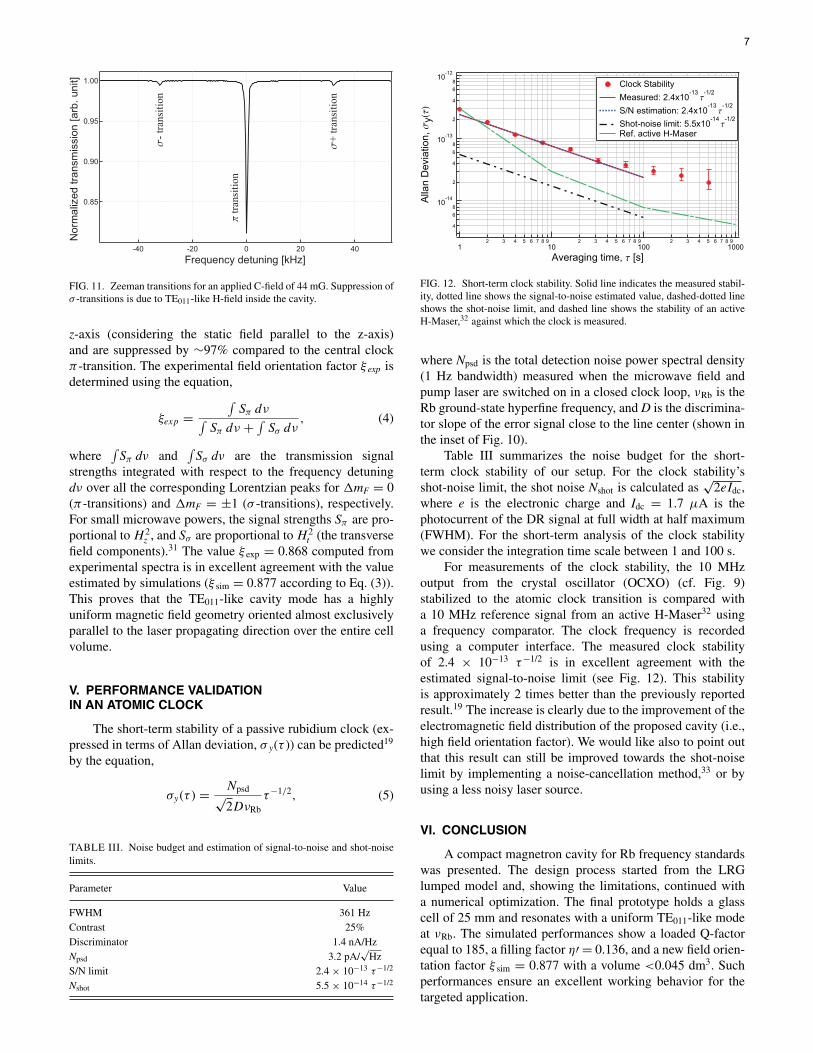
FIG. 11. Zeeman transitions for an applied C-field of 44 mG. Suppression ofσ -transitions is due to TE011-like H-field inside the cavity.
z-axis (considering the static field parallel to the z-axis)and are suppressed by ∼97% compared to the central clockπ -transition. The experimental field orientation factor ξ exp isdetermined using the equation,
ξexp =∫
Sπ dν∫Sπ dν + ∫
Sσ dν, (4)
where∫
Sπ dν and∫
Sσ dν are the transmission signalstrengths integrated with respect to the frequency detuningdν over all the corresponding Lorentzian peaks for �mF = 0(π -transitions) and �mF = ±1 (σ -transitions), respectively.For small microwave powers, the signal strengths Sπ are pro-portional to H 2
z , and Sσ are proportional to H 2t (the transverse
field components).31 The value ξ exp = 0.868 computed fromexperimental spectra is in excellent agreement with the valueestimated by simulations (ξ sim = 0.877 according to Eq. (3)).This proves that the TE011-like cavity mode has a highlyuniform magnetic field geometry oriented almost exclusivelyparallel to the laser propagating direction over the entire cellvolume.
V. PERFORMANCE VALIDATIONIN AN ATOMIC CLOCK
The short-term stability of a passive rubidium clock (ex-pressed in terms of Allan deviation, σ y(τ )) can be predicted19
by the equation,
σy(τ ) = Npsd√2DνRb
τ−1/2, (5)
TABLE III. Noise budget and estimation of signal-to-noise and shot-noiselimits.
Parameter Value
FWHM 361 HzContrast 25%Discriminator 1.4 nA/HzNpsd 3.2 pA/
√Hz
S/N limit 2.4 × 10⁻¹³ τ−1/2
Nshot 5.5 × 10⁻¹⁴ τ−1/2
FIG. 12. Short-term clock stability. Solid line indicates the measured stabil-ity, dotted line shows the signal-to-noise estimated value, dashed-dotted lineshows the shot-noise limit, and dashed line shows the stability of an activeH-Maser,32 against which the clock is measured.
where Npsd is the total detection noise power spectral density(1 Hz bandwidth) measured when the microwave field andpump laser are switched on in a closed clock loop, νRb is theRb ground-state hyperfine frequency, and D is the discrimina-tor slope of the error signal close to the line center (shown inthe inset of Fig. 10).
Table III summarizes the noise budget for the short-term clock stability of our setup. For the clock stability’sshot-noise limit, the shot noise Nshot is calculated as
√2eIdc,
where e is the electronic charge and Idc = 1.7 μA is thephotocurrent of the DR signal at full width at half maximum(FWHM). For the short-term analysis of the clock stabilitywe consider the integration time scale between 1 and 100 s.
For measurements of the clock stability, the 10 MHzoutput from the crystal oscillator (OCXO) (cf. Fig. 9)stabilized to the atomic clock transition is compared witha 10 MHz reference signal from an active H-Maser32 usinga frequency comparator. The clock frequency is recordedusing a computer interface. The measured clock stabilityof 2.4 × 10⁻¹³ τ−1/2 is in excellent agreement with theestimated signal-to-noise limit (see Fig. 12). This stabilityis approximately 2 times better than the previously reportedresult.19 The increase is clearly due to the improvement of theelectromagnetic field distribution of the proposed cavity (i.e.,high field orientation factor). We would like also to point outthat this result can still be improved towards the shot-noiselimit by implementing a noise-cancellation method,33 or byusing a less noisy laser source.
VI. CONCLUSION
A compact magnetron cavity for Rb frequency standardswas presented. The design process started from the LRGlumped model and, showing the limitations, continued witha numerical optimization. The final prototype holds a glasscell of 25 mm and resonates with a uniform TE011-like modeat νRb. The simulated performances show a loaded Q-factorequal to 185, a filling factor η′ = 0.136, and a new field orien-tation factor ξ sim = 0.877 with a volume <0.045 dm3. Suchperformances ensure an excellent working behavior for thetargeted application.
7
Microwave characterization validated the simulatedanalysis albeit experimental results suggest the necessity offurther investigation about modeling of the effect of the Rb.Measured performance (|S11(νRb)| = −6 dB) still allowsclock analysis with a microwave power source as low as−28 dBm.
The suppression of σ -transitions in comparison withπ -transition observed in the double-resonance experimentverified the high uniformity of the microwave magneticfield inside the cavity. This result confirms the necessity ofthe definition of the field orientation factor ξ (in additionto the well known filling factor) to properly characterize aresonator for Rb frequency standards. Excellent agreementis found between the simulated field orientation factor andexperimentally evaluated FOF (ξ sim = 0.877, ξ exp = 0.868,respectively).
The achieved short-term clock stability of 2.4 × 10⁻¹³
τ−1/2 using this compact microwave cavity demonstrates bet-ter stability than that of atomic clocks presently used in satel-lite navigation systems,17 such as the PHM (6.5 × 10⁻¹³
τ−1/2) and RAFS (2.5 × 10⁻¹² τ−1/2). The realization of nextgeneration portable atomic clocks using the demonstratedcompact magnetron cavity for enlarged Rb cells of 25 mmdiameter is thus of high interest for emerging demands inapplications such as telecommunications, satellite navigationsystems, local oscillators (LO) in portable optical frequencysynthesizers and optical frequency standards.
ACKNOWLEDGMENTS
We acknowledge the support from the Swiss NationalScience Foundation (SNSF), the European Space Agency(ESA), and the Alliance and Swiss Space Office (SSO-SER).We also thank F. Gruet, P. Scherler, and M. Durrenberger fromUnine-LTF, and C. E. Calosso from the Istituto Nazionale diRicerca Metrologica (INRIM, Italy).
1J. Vanier and C. Mandache, Appl. Phys. B 87, 565 (2007).2J. Camparo, Phys. Today 60, 33 (2007).3G. Mileti, C. Affolderbach, F. Droz, and E. Murphy, in ESA Bulletin(European Space Agency, 2005), Vol. 122.
4S. Bize, Y. Sortais, M. S. Santos, C. Mandache, A. Clairon, and C. Sa-lomon, Europhys. Lett. 45, 558 (1999).
5J. Vanier and C. Audoin, The Quantum Physics of Atomic Frequency Stan-dards (Adam Hilger, 1989).
6H. Williams, T. Kwon, and T. McClelland, in 37th Annual Symposium onFrequency Control (IEEE conference publications, 1983), pp. 12–17.
7E. Eltsufin, A. Stern, and S. Fel, in Proceedings of the 45th AnnualSymposium on Frequency Control (IEEE conference publications, 1991),pp. 567–571.
8A. Godone, S. Micalizio, F. Levi, and C. Calosso, Rev. Sci. Instrum. 82,074703 (2011).
9G. Rinard and G. Eaton, Biomedical EPR, Part B: Methodology, Instrumen-tation, and Dynamics, Biological Magnetic Resonance Vol. 24/B, edited byS. R. Eaton, G. R. Eaton, and L. J. Berliner (Springer, 2005), pp. 19–52.
10W. Froncisz and J. S. Hyde, J. Magn. Reson. 47, 515 (1982).11W. N. Hardy and L. A. Whitehead, Rev. Sci. Instrum. 52, 213 (1981).12T. Sphicopoulos and F. Gardiol, IEE Proc. Microwaves, Antennas Propag.
H 134, 405 (1987).13B. Xia, D. Zhong, S. An, and G. Mei, IEEE Trans. Instrum. Meas. 55, 1000
(2006).14P. Rochat, H. Schweda, G. Mileti, and G. Busca, in Proceedings of the
IEEE International 48th Frequency Control Symposium (IFCS) (IEEE con-ference publications, 1994), pp. 716–723.
15H. S. Schweda, G. Busca, and P. Rochat, U.S. patent 5,387,881 (1995).16P. Berthoud, I. Pavlenko, Q. Wang, and H. Schweda, in Proceedings of the
IEEE International Frequency Control Symposium (IFCS) and PDA Exhi-bition Jointly with the 17th European Frequency and Time Forum (EFTF)(IEEE conference publications, 2003), pp. 90–94.
17P. Waller, S. Gonzalez, S. Binda, I. Sesia, I. Hidalgo, G. Tobias, and P.Tavella, IEEE Trans. Ultrason. Ferroelectr. Freq. Control 57, 738 (2010).
18G. Mileti, J. Deng, F. L. Walls, D. A. Jennings, and R. E. Drullinger, IEEEJ. Quantum Electron. 34, 233 (1998).
19T. Bandi, C. Affolderbach, C. Calosso, and G. Mileti, Electron. Lett. 47,698 (2011).
20S. Micalizio, C. E. Calosso, A. Godone, and F. Levi, Metrologia 49, 425(2012).
21M. Mehdizadeh and T. Ishii, IEEE Trans. Microwave Theory Tech. 37,1113 (1989).
22W. Piasecki and W. Froncisz, Meas. Sci. Technol. 4, 1363 (1993).23G. B. Collin, Microwave Magnetrons, MIT Radiation Laboratory Series
Vol. 6 (McGraw-Hill, 1948).24High frequency structure simulator (HFSS), version 13.0, 2011, see
http://www.ansoft.com/products/hf/hfss/.25R. Mett, J. Sidabras, and J. Hyde, Appl. Magn. Reson. 31, 573 (2007).26E. Arimondo, M. Inguscio, and P. Violino, Rev. Mod. Phys. 49, 31 (1977).27R. E. Collin, Foundations for Microwave Engineering (McGraw-Hill,
1966).28C. Affolderbach, F. Gruet, D. Miletic, and G. Mileti, in Proceedings of
the 7th Symposium on Frequency Standards and Metrology, USA, 5–11October 2008, edited by L. Maleki (World Scientific, 2009), pp. 363–367.
29C. Affolderbach and G. Mileti, Rev. Sci. Instrum. 76, 073108 (2005).30J. Ye, S. Swartz, P. Jungner, and J. L. Hall, Opt. Lett. 21, 1280 (1996).31G. Mileti and P. Thomann, in Proceedings of the 9th European Frequency
and Time Forum (EFTF), Besançon, France, 8–10 March 1995, edited byD. Hauden, (ACTES proceedings, 1995), pp. 271–276.
32R. Vessot, Metrologia 42, S80 (2005).33C. Affolderbach, F. Gruet, R. Matthey, and G. Mileti, in Proceedings of the
IEEE Frequency Control Symposium and European Frequency and TimeForum (IEEE conference publications, 2011), p. 944.
8