Embed Size (px)
Citation preview
C. R. Physique 17 (2016) 893–907
Contents lists available at ScienceDirect
Comptes Rendus Physique
www.sciencedirect.com
Polariton physics/Physique des polaritons
Lattices of quantized vortices in polariton superfluids
Réseaux de tourbillons quantifiés dans les superfluides de polaritons
Thomas Boulier, Emiliano Cancellieri, Nicolas D. Sangouard, Romain Hivet, Quentin Glorieux, Élisabeth Giacobino, Alberto Bramati ∗
Laboratoire Kastler Brossel, UPMC – Sorbonne Universités, CNRS, ENS-PSL, Research University, Collège de France, 4, place Jussieu, case 74, 75005 Paris, France
a r t i c l e i n f o a b s t r a c t
Article history:Available online 13 June 2016
Keywords:PolaritonsQuantum fluids of lightNonlinear optics
Mots-clés :PolaritonsFluides quantiques de lumièreOptique non linéaire
In this review, we will focus on the description of the recent studies conducted in the quest for the observation of lattices of quantized vortices in resonantly injected polariton superfluids. In particular, we will show how the implementation of optical traps for polaritons allows for the realization of vortex–antivortex lattices in confined geometries and how the development of a flexible method to inject a controlled orbital angular momentum (OAM) in such systems results in the observation of patterns of same-sign vortices.
© 2016 Académie des sciences. Published by Elsevier Masson SAS. This is an open access article under the CC BY-NC-ND license
(http://creativecommons.org/licenses/by-nc-nd/4.0/).
r é s u m é
Dans cet article de synthèse, nous nous concentrerons sur la description d’études récentes menées dans le but d’observer des réseaux de tourbillons quantifiés dans des superfluides de polaritons injectés de manière résonante. En particulier, nous montrerons comment l’implémentation de pièges optiques pour les polaritons permet la réalisation de réseaux tourbillon–anti-tourbillon dans des géométries confinées et comment le développement d’une méthode flexible pour injecter un moment angulaire orbital contrôlé (OAM) dans de tels systèmes permet l’observation de motifs de tourbillons de mêmes signes.
© 2016 Académie des sciences. Published by Elsevier Masson SAS. This is an open access article under the CC BY-NC-ND license
(http://creativecommons.org/licenses/by-nc-nd/4.0/).
1. Introduction
In semiconductor microcavities [1,2], polaritons, the half-light, half-matter particles arising from strong coupling be-tween excitons and photons behave like weakly interacting composite bosons. Due to their excitonic part, they exhibit non-linear interactions, while their photonic part allows creating and detecting them optically. In this sense, the polariton system is part of a wider family of systems where an effective photon–photon interaction can be engineered, resulting in a hydrodynamical-like behavior. Such systems are labeled as quantum fluids of light [3].
* Corresponding author.E-mail address: [email protected] (A. Bramati).
http://dx.doi.org/10.1016/j.crhy.2016.05.0051631-0705/© 2016 Académie des sciences. Published by Elsevier Masson SAS. This is an open access article under the CC BY-NC-ND license (http://creativecommons.org/licenses/by-nc-nd/4.0/).
894 T. Boulier et al. / C. R. Physique 17 (2016) 893–907
A coherent polariton gas of large density can be obtained by resonant laser excitation [4], which allows probing any specific state of the polariton dispersion. Density, phase, temporal and spatial coherence, but also motion, can be directly accessed by well-developed optical techniques. Any type of in-plane potential landscape can be designed by lateral pattern-ing of microcavities, mesa fabrication [5], or by using optical potentials induced by exciton–exciton interactions, as recently demonstrated in references [6,7].
All these ingredients make polariton systems a unique platform to study quantum fluid effects in a semiconductor chip and to evidence properties very difficult to access in other systems. This has been clearly demonstrated by the numerous results obtained since the first observation of polariton BEC [8]. Superfluidity and Cerenkov regime of polaritons have been demonstrated in 2009 [4] with an original experimental scheme based on the interaction between a dense mono-kinetic flow of polaritons and a defect. This allowed confirming the superfluid nature of a polariton flow and to observe, for the first time, the formation of oblique-dark and bright-dissipative solitons [9–11].
For what concerns the observation of vortices, several works have focused on this subject but, so far, only few of them focus on arrays of vortex–antivortex pairs and of vortices of the same sign. Among the others, of particular relevance is the work of Keeling and Berloff, theoretically studying [12] the formation of a rotating polariton BEC, pumped out of resonance trapped in a harmonic potential. From the experimental point of view, the nucleation of vortices has been addressed in non-resonant configurations, as well as in resonant configurations and in optical parametric oscillator (OPO) schemes. For what concerns out-of-resonant schemes, vortex formation in disordered landscapes has been achieved [13] and hydrody-namical nucleation of vortex pairs have been observed by colliding a flux of polaritons on a structural defect of a planar cavity [14]. Regarding resonantly pumped systems, vortex formation has been observed, similarly to the out-of-resonant case, by colliding a moving fluid of polaritons with a structural defect of a planar cavity [9,15]. In these cases, however, a metallic mask has been used to block the laser pump in the region behind the defect, in order to allow the phase of the scattered polaritons to evolve freely. Finally, vortices have also been observed in the optical parametric oscillator (OPO) scheme [16,17].
We will show in the following that the new possibilities offered by confining polaritons in optically generated potential traps allow creating interaction-shaped vortex–antivortex lattices [18,19]; moreover, we will illustrate a new flexible method based on the use of a spatial light modulator (SLM) for the direct phase imprint in a polariton fluid; this allows the creation of a rotating polariton fluid in an annular geometry, leading to the formation of a chain of same-sign vortices [20]. These results constitute a significant step forward in our understanding of the quantum fluids of light and open the way to the study of Abrikosov-like physics in these systems.
1.1. Sample
The planar microcavity used in the present work was built by using the molecular beam epitaxy technique at the “École polytechnique fédérale de Lausanne” (EPFL), Switzerland, by Romuald Houdré [21,22]. The sample is made of three In0,04Ga0,96As quantum wells placed at the antinodes of the cavity electromagnetic field.
The cavity is GaAs-based with a typical length 2λ/nc for λ = 835 nm (the excitonic resonance), where nc = 3.54 is the cavity GaAs substrate optical index. The Bragg mirrors forming the cavity are made of 21 (front mirror) and 24 (back mirror) GaAs–AlAs pairs. The measured polariton linewidth is less than 85 μeV (limited by the spectrometer resolution), and the polariton lifetime is estimated at about 15 ps from time resolved measurements. The back mirror lies on a GaAs substrate polished to allow working in transmission mode. During epitaxial growth, a very small angle of the order of 10−4 degrees was implemented between the Bragg mirrors to continuously change the cavity thickness. This angle allows for a very fine control of the photon–exciton detuning. The change in the cavity thickness modifies linearly the energy of the cavity photon with the position on the sample while the exciton energy remains constant. Exciton–photon detuning from +8 meV to −4 meV can be achieved, with an energy gradient of about 710 μeV mm−1. The Rabi splitting for our sample is measured to be 5.1 meV.
1.2. Injection methods
There are two main methods to inject polaritons in a microcavity. One is the so-called “out-of-resonance” pumping and consists in injecting in the cavity high-energy photons with a laser. Depending on the efficiency of the relaxation phenomena, polaritons can thermalize and form a quasi-Bose–Einstein condensate [8]. With this injection method, a large exciton population is created in addition to the polariton population. The second technique to create a fluid of polaritons is “resonant injection” (or “quasi-resonant”), which we will use in the following. It consists in injecting laser photons directly at an energy and in-plane wavevector resonant with the lower polariton branch. In this way, the energy and the wavevector of the resulting polariton population are fully controlled. Using a continuous laser, we can create large polariton populations whose properties (momentum, energy, density, phase, spin) are inherited from the pump. This controlled injection allows the study of propagation-related phenomena [4,23,24], and quantum hydrodynamic experiments are achievable under this pumping scheme. Note that this is unlike the out-of-resonance setup, where the coherence and the in-plane wavevector of the pump are lost during the relaxation process. In the quasi-resonant scheme, one can induce a small energy difference between the laser and the polariton energy. With this quasi-resonant pumping, the nonlinearities play an important role and induce a bistable behavior accompanied by many interesting phenomena [3,4].
T. Boulier et al. / C. R. Physique 17 (2016) 893–907 895
1.3. Theoretical model
A standard way to model the dynamics of resonantly driven polaritons in a planar microcavity is to use a Gross–Pitaevskii equation for coupled cavity and exciton fields (�C and �X) generalized to include the effects of the resonant pumping and decay (h = 1),
∂t
(�X�C
)=
(0F
)+
[H0 +
(gX|�X|2 0
0 V C
)](�X�C
)(1)
with the linear polariton Hamiltonian H0 given by:
H0 =(
ωX − iγX �R/2�R/2 ωC(k//) − iγC
)(2)
where the cavity dispersion is given by
ωC(k//) = ωC(0) + hk2//
2mC(3)
with the cavity photon effective mass mC = 4 × 10⁻⁵m0, where m0 is the bare electron mass. The photon effective mass comes from the parabolic shape of the cavity dispersion curve.
hωC = hc√
k2z + k2
// ≈ hckz + h2k2//
2mCwith mC = hkz
c
where kz is the momentum component perpendicular to the cavity plane and k// is the component parallel to the cavity plane.
For the simulations presented in the following, we have assumed a flat exciton dispersion relation ωX(k//) = ωX(0). The parameters �R, γX, and γC are the Rabi splitting and the excitonic and photonic decay rates, respectively, and have been fixed to values close to experimental ones: �R = 5.1 meV, γX = 0.04 meV, and γC = 0.06 meV. In this model, polaritons are injected into the cavity by a coherent and monochromatic laser field, with a pump intensity fp and an arbitrary spatial profile F (r). Here, in contrast to other cases [25], we simulate the polariton system with a simplified two-field model, discarding the role of the excitonic reservoir since our setup is based on the use of a continuous-wave laser with a linewidth orders of magnitudes smaller than the Rabi splitting, and therefore the injection of a reservoir of excitons is strongly suppressed. The exciton–exciton interaction strength gX is set to 1 by rescaling both the cavity and excitonic fields and the pump intensities. All the analyzed quantities are taken when the system has reached a steady-state condition after a transient period of 200 ps.
2. Generation of vortex–antivortex lattices in confined geometries
Vortex dynamics have bee extensively studied in several experiments, which showed the hydrodynamical nucleation of vortex–antivortex (V–AV) pairs [9,10,12,26,27], single vortex stability in pulsed pumped regime and V–AV trapping by natural disorder [16,28,29]. Some studies focused on the steady-state solution for polariton vortices held in controlled traps [30,31].
2.1. Setup description
In continuity with previous studies of trapped polariton vortices [26,27], our goal is here to study the geometric self-organization of vortices in a steady-state regime. Indeed, a steady-state regime is observable with a time-averaged setup such as the one we use in this study. To observe the formation of a stable V–AV lattice, we create a trapping potential by spatially modulating the Gaussian pump beam with an opaque mask and making use of polariton–polariton interactions: by cutting the center of the Gaussian pump laser with the mask, the polariton density (and thus the polariton–polariton potential energy) is high around the masked region and low inside. The shape of the trap is fixed by the spatial geometry of the masked zone, created with a metallic mask whose shape we can engineer at will.
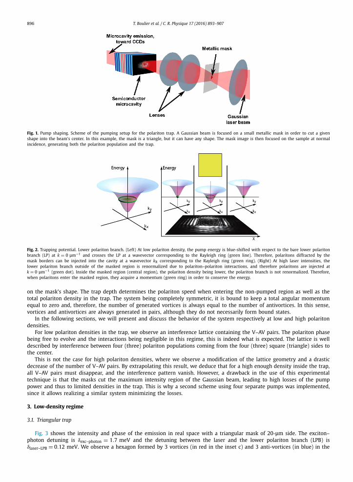
In this study, we used either a square or a triangular mask with sides of 45 μm. The laser is focused on the mask with a waist larger than 45 μm. The mask image is projected onto the microcavity at normal incidence, as shown in Fig. 1. Therefore, laser intensity is locally set to zero in the mask image, placed at the beam’s center.
The difference in interaction energy (or equivalently, polariton density) between the non-masked (with high polariton density) and masked regions (with low polariton density) accelerates polaritons towards the non-pumped center. Indeed, polaritons “fall” into the trap, their interaction energy being converted in kinetic energy, from the four (square) or three (triangle) sides. This is illustrated in Fig. 2. The absence of pump inside the trap ensures the free evolution of the polariton phase; on the contrary, in the pumped region, the polariton phase is locked to the pump phase. Polaritons coming inside the trap from the trap sides meet and interact, giving rise to V–AV pairs arranged in a lattice. The lattice geometry depends
896 T. Boulier et al. / C. R. Physique 17 (2016) 893–907
Fig. 1. Pump shaping. Scheme of the pumping setup for the polariton trap. A Gaussian beam is focused on a small metallic mask in order to cut a given shape into the beam’s center. In this example, the mask is a triangle, but it can have any shape. The mask image is then focused on the sample at normal incidence, generating both the polariton population and the trap.
Fig. 2. Trapping potential. Lower polariton branch. (Left) At low polariton density, the pump energy is blue-shifted with respect to the bare lower polariton branch (LP) at k = 0 μm−1 and crosses the LP at a wavevector corresponding to the Rayleigh ring (green line). Therefore, polaritons diffracted by the mask borders can be injected into the cavity at a wavevector kR corresponding to the Rayleigh ring (green ring). (Right) At high laser intensities, the lower polariton branch outside of the masked region is renormalized due to polariton–polariton interactions, and therefore polaritons are injected at k = 0 μm−1 (green dot). Inside the masked region (central region), the polariton density being lower, the polariton branch is not renormalized. Therefore, when polaritons enter the masked region, they acquire a momentum (green ring) in order to conserve the energy.
on the mask’s shape. The trap depth determines the polariton speed when entering the non-pumped region as well as the total polariton density in the trap. The system being completely symmetric, it is bound to keep a total angular momentum equal to zero and, therefore, the number of generated vortices is always equal to the number of antivortices. In this sense, vortices and antivortices are always generated in pairs, although they do not necessarily form bound states.
In the following sections, we will present and discuss the behavior of the system respectively at low and high polariton densities.
For low polariton densities in the trap, we observe an interference lattice containing the V–AV pairs. The polariton phase being free to evolve and the interactions being negligible in this regime, this is indeed what is expected. The lattice is well described by interference between four (three) polariton populations coming from the four (three) square (triangle) sides to the center.
This is not the case for high polariton densities, where we observe a modification of the lattice geometry and a drastic decrease of the number of V–AV pairs. By extrapolating this result, we deduce that for a high enough density inside the trap, all V–AV pairs must disappear, and the interference pattern vanish. However, a drawback in the use of this experimental technique is that the masks cut the maximum intensity region of the Gaussian beam, leading to high losses of the pump power and thus to limited densities in the trap. This is why a second scheme using four separate pumps was implemented, since it allows realizing a similar system minimizing the losses.
3. Low-density regime
3.1. Triangular trap
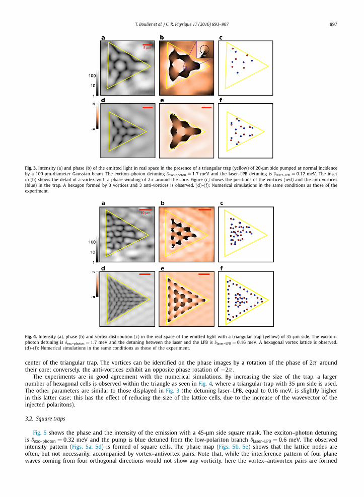
Fig. 3 shows the intensity and phase of the emission in real space with a triangular mask of 20-μm side. The exciton–photon detuning is δexc–photon = 1.7 meV and the detuning between the laser and the lower polariton branch (LPB) is δlaser–LPB = 0.12 meV. We observe a hexagon formed by 3 vortices (in red in the inset c) and 3 anti-vortices (in blue) in the
T. Boulier et al. / C. R. Physique 17 (2016) 893–907 897
Fig. 3. Intensity (a) and phase (b) of the emitted light in real space in the presence of a triangular trap (yellow) of 20-μm side pumped at normal incidence by a 100-μm-diameter Gaussian beam. The exciton–photon detuning δexc–photon = 1.7 meV and the laser–LPB detuning is δlaser–LPB = 0.12 meV. The inset in (b) shows the detail of a vortex with a phase winding of 2π around the core. Figure (c) shows the positions of the vortices (red) and the anti-vortices (blue) in the trap. A hexagon formed by 3 vortices and 3 anti-vortices is observed. (d)–(f): Numerical simulations in the same conditions as those of the experiment.
Fig. 4. Intensity (a), phase (b) and vortex-distribution (c) in the real space of the emitted light with a triangular trap (yellow) of 35-μm side. The exciton–photon detuning is δexc–photon = 1.7 meV and the detuning between the laser and the LPB is δlaser–LPB = 0.16 meV. A hexagonal vortex lattice is observed. (d)–(f): Numerical simulations in the same conditions as those of the experiment.
center of the triangular trap. The vortices can be identified on the phase images by a rotation of the phase of 2π around their core; conversely, the anti-vortices exhibit an opposite phase rotation of −2π .
The experiments are in good agreement with the numerical simulations. By increasing the size of the trap, a larger number of hexagonal cells is observed within the triangle as seen in Fig. 4, where a triangular trap with 35 μm side is used. The other parameters are similar to those displayed in Fig. 3 (the detuning laser–LPB, equal to 0.16 meV, is slightly higher in this latter case; this has the effect of reducing the size of the lattice cells, due to the increase of the wavevector of the injected polaritons).
3.2. Square traps
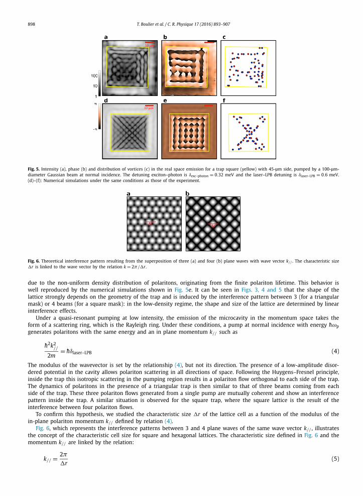
Fig. 5 shows the phase and the intensity of the emission with a 45-μm side square mask. The exciton–photon detuning is δexc–photon = 0.32 meV and the pump is blue detuned from the low-polariton branch δlaser–LPB = 0.6 meV. The observed intensity pattern (Figs. 5a, 5d) is formed of square cells. The phase map (Figs. 5b, 5e) shows that the lattice nodes are often, but not necessarily, accompanied by vortex–antivortex pairs. Note that, while the interference pattern of four plane waves coming from four orthogonal directions would not show any vorticity, here the vortex–antivortex pairs are formed
898 T. Boulier et al. / C. R. Physique 17 (2016) 893–907
Fig. 5. Intensity (a), phase (b) and distribution of vortices (c) in the real space emission for a trap square (yellow) with 45-μm side, pumped by a 100-μm-diameter Gaussian beam at normal incidence. The detuning exciton–photon is δexc–photon = 0.32 meV and the laser–LPB detuning is δlaser–LPB = 0.6 meV. (d)–(f): Numerical simulations under the same conditions as those of the experiment.
Fig. 6. Theoretical interference pattern resulting from the superposition of three (a) and four (b) plane waves with wave vector k// . The characteristic size r is linked to the wave vector by the relation k = 2π/r.
due to the non-uniform density distribution of polaritons, originating from the finite polariton lifetime. This behavior is well reproduced by the numerical simulations shown in Fig. 5e. It can be seen in Figs. 3, 4 and 5 that the shape of the lattice strongly depends on the geometry of the trap and is induced by the interference pattern between 3 (for a triangular mask) or 4 beams (for a square mask): in the low-density regime, the shape and size of the lattice are determined by linear interference effects.
Under a quasi-resonant pumping at low intensity, the emission of the microcavity in the momentum space takes the form of a scattering ring, which is the Rayleigh ring. Under these conditions, a pump at normal incidence with energy hωpgenerates polaritons with the same energy and an in plane momentum k// such as
h2k2//
2m= hδlaser–LPB (4)
The modulus of the wavevector is set by the relationship (4), but not its direction. The presence of a low-amplitude disor-dered potential in the cavity allows polariton scattering in all directions of space. Following the Huygens–Fresnel principle, inside the trap this isotropic scattering in the pumping region results in a polariton flow orthogonal to each side of the trap. The dynamics of polaritons in the presence of a triangular trap is then similar to that of three beams coming from each side of the trap. These three polariton flows generated from a single pump are mutually coherent and show an interference pattern inside the trap. A similar situation is observed for the square trap, where the square lattice is the result of the interference between four polariton flows.
To confirm this hypothesis, we studied the characteristic size r of the lattice cell as a function of the modulus of the in-plane polariton momentum k// defined by relation (4).
Fig. 6, which represents the interference patterns between 3 and 4 plane waves of the same wave vector k// , illustrates the concept of the characteristic cell size for square and hexagonal lattices. The characteristic size defined in Fig. 6 and the momentum k// are linked by the relation:
k// = 2π(5)
r
T. Boulier et al. / C. R. Physique 17 (2016) 893–907 899
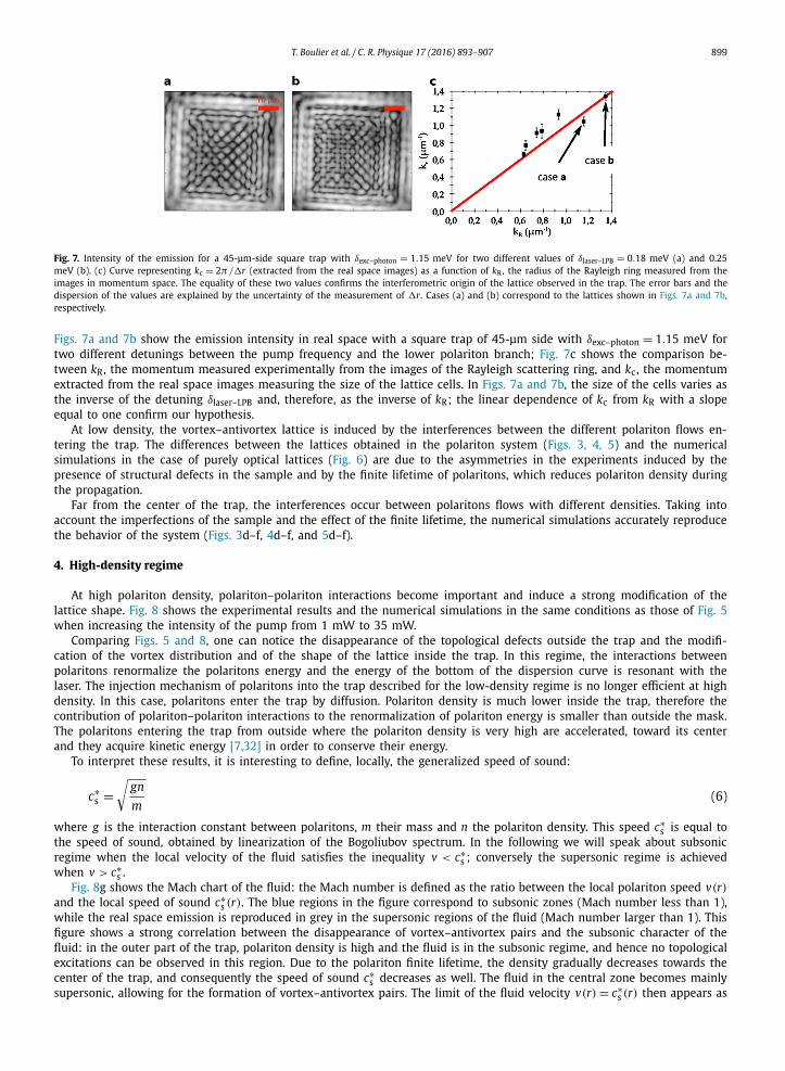
Fig. 7. Intensity of the emission for a 45-μm-side square trap with δexc–photon = 1.15 meV for two different values of δlaser–LPB = 0.18 meV (a) and 0.25 meV (b). (c) Curve representing kc = 2π/r (extracted from the real space images) as a function of kR, the radius of the Rayleigh ring measured from the images in momentum space. The equality of these two values confirms the interferometric origin of the lattice observed in the trap. The error bars and the dispersion of the values are explained by the uncertainty of the measurement of r. Cases (a) and (b) correspond to the lattices shown in Figs. 7a and 7b, respectively.
Figs. 7a and 7b show the emission intensity in real space with a square trap of 45-μm side with δexc–photon = 1.15 meV for two different detunings between the pump frequency and the lower polariton branch; Fig. 7c shows the comparison be-tween kR, the momentum measured experimentally from the images of the Rayleigh scattering ring, and kc, the momentum extracted from the real space images measuring the size of the lattice cells. In Figs. 7a and 7b, the size of the cells varies as the inverse of the detuning δlaser–LPB and, therefore, as the inverse of kR; the linear dependence of kc from kR with a slope equal to one confirm our hypothesis.
At low density, the vortex–antivortex lattice is induced by the interferences between the different polariton flows en-tering the trap. The differences between the lattices obtained in the polariton system (Figs. 3, 4, 5) and the numerical simulations in the case of purely optical lattices (Fig. 6) are due to the asymmetries in the experiments induced by the presence of structural defects in the sample and by the finite lifetime of polaritons, which reduces polariton density during the propagation.
Far from the center of the trap, the interferences occur between polaritons flows with different densities. Taking into account the imperfections of the sample and the effect of the finite lifetime, the numerical simulations accurately reproduce the behavior of the system (Figs. 3d–f, 4d–f, and 5d–f).
4. High-density regime
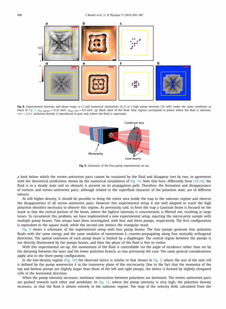
At high polariton density, polariton–polariton interactions become important and induce a strong modification of the lattice shape. Fig. 8 shows the experimental results and the numerical simulations in the same conditions as those of Fig. 5when increasing the intensity of the pump from 1 mW to 35 mW.
Comparing Figs. 5 and 8, one can notice the disappearance of the topological defects outside the trap and the modifi-cation of the vortex distribution and of the shape of the lattice inside the trap. In this regime, the interactions between polaritons renormalize the polaritons energy and the energy of the bottom of the dispersion curve is resonant with the laser. The injection mechanism of polaritons into the trap described for the low-density regime is no longer efficient at high density. In this case, polaritons enter the trap by diffusion. Polariton density is much lower inside the trap, therefore the contribution of polariton–polariton interactions to the renormalization of polariton energy is smaller than outside the mask. The polaritons entering the trap from outside where the polariton density is very high are accelerated, toward its center and they acquire kinetic energy [7,32] in order to conserve their energy.
To interpret these results, it is interesting to define, locally, the generalized speed of sound:
c∗s =
√gn
m(6)
where g is the interaction constant between polaritons, m their mass and n the polariton density. This speed c∗s is equal to
the speed of sound, obtained by linearization of the Bogoliubov spectrum. In the following we will speak about subsonic regime when the local velocity of the fluid satisfies the inequality v < c∗
s ; conversely the supersonic regime is achieved when v > c∗
s .Fig. 8g shows the Mach chart of the fluid: the Mach number is defined as the ratio between the local polariton speed v(r)
and the local speed of sound c∗s (r). The blue regions in the figure correspond to subsonic zones (Mach number less than 1),
while the real space emission is reproduced in grey in the supersonic regions of the fluid (Mach number larger than 1). This figure shows a strong correlation between the disappearance of vortex–antivortex pairs and the subsonic character of the fluid: in the outer part of the trap, polariton density is high and the fluid is in the subsonic regime, and hence no topological excitations can be observed in this region. Due to the polariton finite lifetime, the density gradually decreases towards the center of the trap, and consequently the speed of sound c∗
s decreases as well. The fluid in the central zone becomes mainly supersonic, allowing for the formation of vortex–antivortex pairs. The limit of the fluid velocity v(r) = c∗
s (r) then appears as
900 T. Boulier et al. / C. R. Physique 17 (2016) 893–907
Fig. 8. Experimental intensity and phase maps (a–c) and numerical simulations (d–f) at a high pump intensity (35 mW) under the same conditions as those of Fig. 5. δexc–photon = 0.32 meV, δlaser–LPB = 0.6 meV. (g) Mach chart of the fluid: blue regions correspond to points where the fluid is subsonic, v(r) < c∗
s (r); polariton density is reproduced in grey only where the fluid is supersonic.
Fig. 9. Schematic of the four-pump experimental set-up.
a limit below which the vortex–antivortex pairs cannot be sustained by the fluid and disappear two by two, in agreement with the theoretical predictions shown by the numerical simulations of Fig. 14. Note that here, differently from [10,14], the fluid is in a steady state and no obstacle is present on its propagation path. Therefore, the formation and disappearance of vortices and vortex–antivortex pairs, although related to the superfluid character of the polariton state, are of different natures.
At still higher density, it should be possible to bring the entire area inside the trap in the subsonic regime and observe the disappearence of all vortex–antivortex pairs. However this experimental setup it not well adapted to reach the high polariton densities necessary to observe this regime. As previously said, to form the trap a Gaussian beam is focused on the mask so that the central portion of the beam, where the highest intensity is concentrated, is filtered out, resulting in large losses. To circumvent this problem, we have implemented a new experimental setup, injecting the microcavity sample with multiple pump beams. Two setups have been investigated, with four and three pumps, respectively. The first configuration is equivalent to the square mask, while the second one mimics the triangular mask.
Fig. 9 shows a schematic of the experimental setup with four pump beams. The four pumps generate four polariton fluids with the same energy and the same modulus of momentum k, counter-propagating along four mutually orthogonal directions. The spatial extension of each pump beam is limited by a diaphragm. The central region between the pumps is not directly illuminated by the pumps beams, and then the phase of the fluid is free to evolve.
With this experimental set-up, the momentum of the fluid is controllable via the angle of incidence rather than set by the detuning between the laser and the lower polariton branch, as was previously the case. The same general considerations apply also to the three-pump configuration.
In the low-density regime (Fig. 10) the observed lattice is similar to that shown in Fig. 5, where the size of the unit cell is defined by the pump wavevector k in the transverse plane of the microcavity. Due to the fact that the momenta of the top and bottom pumps are slightly larger than those of the left and right pumps, the lattice is formed by slightly elongated cells in the horizontal direction.
When the pump intensity increases, nonlinear interactions between polaritons are dominant. The vortex–antivortex pairs are pushed towards each other and annihilate. In Fig. 11, where the pump intensity is very high, the polariton density increases, so that the fluid is almost entirely in the subsonic regime. The map of the velocity field, calculated from the
T. Boulier et al. / C. R. Physique 17 (2016) 893–907 901
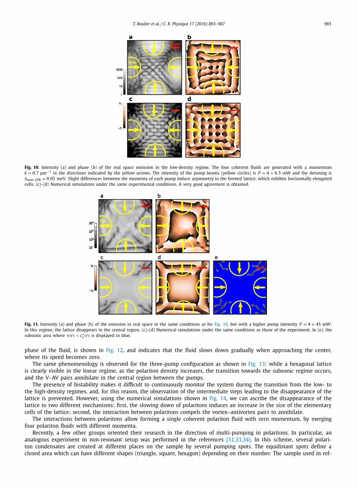
Fig. 10. Intensity (a) and phase (b) of the real space emission in the low-density regime. The four coherent fluids are generated with a momentum k = 0.7 μm−1 in the directions indicated by the yellow arrows. The intensity of the pump beams (yellow circles) is P = 4 × 6.5 mW and the detuning is δlaser–LPB = 0.05 meV. Slight differences between the momenta of each pump induce asymmetry in the formed lattice, which exhibits horizontally elongated cells. (c)–(d) Numerical simulations under the same experimental conditions. A very good agreement is obtained.
Fig. 11. Intensity (a) and phase (b) of the emission in real space in the same conditions as for Fig. 10, but with a higher pump intensity P = 4 × 45 mW. In this regime, the lattice disappears in the central region. (c)–(d) Numerical simulations under the same conditions as those of the experiment. In (e), the subsonic area where v(r) < c∗
s (r) is displayed in blue.
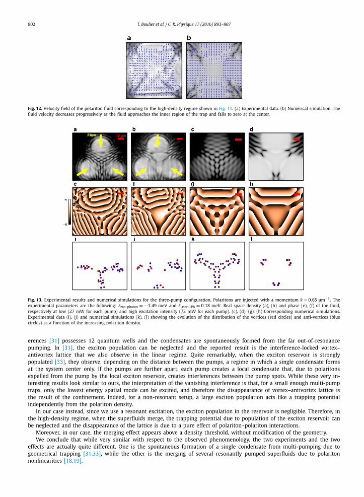
phase of the fluid, is shown in Fig. 12, and indicates that the fluid slows down gradually when approaching the center, where its speed becomes zero.
The same phenomenology is observed for the three-pump configuration as shown in Fig. 13: while a hexagonal lattice is clearly visible in the linear regime, as the polariton density increases, the transition towards the subsonic regime occurs, and the V–AV pairs annihilate in the central region between the pumps.
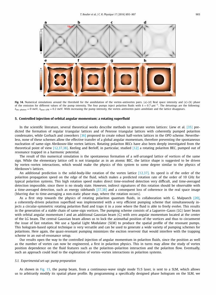
The presence of bistability makes it difficult to continuously monitor the system during the transition from the low- to the high-density regimes, and, for this reason, the observation of the intermediate steps leading to the disappearance of the lattice is prevented. However, using the numerical simulations shown in Fig. 14, we can ascribe the disappearance of the lattice to two different mechanisms: first, the slowing down of polaritons induces an increase in the size of the elementary cells of the lattice; second, the interaction between polaritons compels the vortex–antivortex pairs to annihilate.
The interactions between polaritons allow forming a single coherent polariton fluid with zero momentum, by merging four polariton fluids with different momenta.
Recently, a few other groups oriented their research in the direction of multi-pumping in polaritons. In particular, an analogous experiment in non-resonant setup was performed in the references [31,33,34]. In this scheme, several polari-ton condensates are created at different places on the sample by several pumping spots. The equidistant spots define a closed area which can have different shapes (triangle, square, hexagon) depending on their number. The sample used in ref-
902 T. Boulier et al. / C. R. Physique 17 (2016) 893–907
Fig. 12. Velocity field of the polariton fluid corresponding to the high-density regime shown in Fig. 11. (a) Experimental data. (b) Numerical simulation. The fluid velocity decreases progressively as the fluid approaches the inner region of the trap and falls to zero at the center.
Fig. 13. Experimental results and numerical simulations for the three-pump configuration. Polaritons are injected with a momentum k = 0.65 μm−1. The experimental parameters are the following: δexc–photon = −1.49 meV and δlaser–LPB = 0.18 meV. Real space density (a), (b) and phase (e), (f) of the fluid, respectively at low (27 mW for each pump) and high excitation intensity (72 mW for each pump). (c), (d), (g), (h) Corresponding numerical simulations. Experimental data (i), (j) and numerical simulations (k), (l) showing the evolution of the distribution of the vortices (red circles) and anti-vortices (blue circles) as a function of the increasing polariton density.
erences [31] possesses 12 quantum wells and the condensates are spontaneously formed from the far out-of-resonance pumping. In [31], the exciton population can be neglected and the reported result is the interference-locked vortex–antivortex lattice that we also observe in the linear regime. Quite remarkably, when the exciton reservoir is strongly populated [33], they observe, depending on the distance between the pumps, a regime in which a single condensate forms at the system center only. If the pumps are further apart, each pump creates a local condensate that, due to polaritons expelled from the pump by the local exciton reservoir, creates interferences between the pump spots. While these very in-teresting results look similar to ours, the interpretation of the vanishing interference is that, for a small enough multi-pump traps, only the lowest energy spatial mode can be excited, and therefore the disappearance of vortex–antivortex lattice is the result of the confinement. Indeed, for a non-resonant setup, a large exciton population acts like a trapping potential independently from the polariton density.
In our case instead, since we use a resonant excitation, the exciton population in the reservoir is negligible. Therefore, in the high-density regime, when the superfluids merge, the trapping potential due to population of the exciton reservoir can be neglected and the disappearance of the lattice is due to a pure effect of polariton–polariton interactions.
Moreover, in our case, the merging effect appears above a density threshold, without modification of the geometry.We conclude that while very similar with respect to the observed phenomenology, the two experiments and the two
effects are actually quite different. One is the spontaneous formation of a single condensate from multi-pumping due to geometrical trapping [31,33], while the other is the merging of several resonantly pumped superfluids due to polariton nonlinearities [18,19].
T. Boulier et al. / C. R. Physique 17 (2016) 893–907 903
Fig. 14. Numerical simulations around the threshold for the annihilation of the vortex–antivortex pairs. (a)–(d) Real space intensity and (e)–(h) phase of the emission for different values of the pump intensity. The four pumps inject polariton fluids with k = 0.7 μm−1. The detunings are the following: δexc–photon = 0 meV, δlaser–LPB = 0.2 meV. With increasing the pump intensity, the vortex–antivortex pairs annihilate and the lattice disappears.
5. Controlled injection of orbital angular momentum: a rotating superfluid
In the scientific literature, several theoretical works describe methods to generate vortex lattices: Liew et al. [35] pre-dicted the formation of regular triangular lattices and of Penrose triangular lattices with coherently pumped polariton condensates, while Gorbach and coworkers [36] proposed to create robust half-vortex lattices in the OPO scheme. Neverthe-less, none of these schemes allow the effective transfer of a global angular momentum, therefore preventing the spontaneous nucleation of same-sign Abrikosov-like vortex lattices. Rotating polariton BECs have also been deeply investigated from the theoretical point of view [12,37,38]. Keeling and Berloff, in particular, studied [12] a rotating polariton BEC, pumped out of resonance trapped in a harmonic potential.
The result of this numerical simulation is the spontaneous formation of a self-arranged lattice of vortices of the same sign. While the elementary lattice cell is not triangular as in an atomic BEC, the lattice shape is suggested to be driven by vortex–vortex interactions, which would make the physics of this system to some degree similar to the physics of Abrikosov’s lattices.
An additional prediction is the solid-body-like rotation of the vortex lattice [12,37]. Its speed is of the order of the polariton propagation speed on the edge of the fluid, which makes a predicted rotation rate of the order of 10 GHz for typical polariton systems. This high rotation speed makes direct time-resolved detection very difficult, and time-averaged detection impossible, since there is no steady state. However, indirect signatures of this rotation should be observable with a time-averaged detection, such as energy sidebands [37,38] and a consequent loss of coherence in the real space image (blurring due to time-averaging a non-static phase map, where the rotation occurs).
As a first step towards the physics of rotating polariton quantum fluids, in collaboration with G. Malpuech [20], a coherently-driven polariton superfluid was implemented with a very efficient pumping scheme that simultaneously in-jects a circular-symmetric rotating polariton fluid and traps it in a zone where the fluid is able to freely evolve. This results in the generation of a stable chain of same-sign vortices. The pumping scheme consists of a Laguerre–Gauss (LG) laser beam with orbital angular momentum l and an additional Gaussian beam (G) with zero angular momentum located at the center of the LG beam. The central Gaussian beam allows us to lock the azimuthal position of the vortices and thus to circumvent the issue of fast rotation. We use a Spatial Light Modulator (SLM) to produce the spatial profile of the resonant pumps. This hologram-based optical technique is very versatile and can be used to generate a wide variety of pumping schemes for polaritons. Here again, the quasi-resonant pumping minimizes the exciton reservoir that would interfere with the trapping scheme in an out-of-resonance setup.
Our results open the way to the controlled injection of angular momentum in polariton fluids, since the position as well as the number of vortex can now be engineered, a first in polariton physics. This in turns may allow the study of vortex position dependence on the fluid features such as the polariton–polariton interaction and the polariton flow. Eventually, such an approach could lead to the exploration of vortex–vortex interactions in polariton systems.
5.1. Experimental set-up: pump preparation
As shown in Fig. 15, the pump beam, from a continuous-wave single mode Ti:S laser, is sent to a SLM, which allows us to arbitrarily modify its spatial phase profile. By programming a specifically designed phase hologram on the SLM, we
904 T. Boulier et al. / C. R. Physique 17 (2016) 893–907
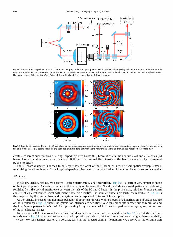
Fig. 15. Scheme of the experimental setup. The pumps are prepared with a pure-phase Spatial Light Modulator (SLM) and sent onto the sample. The sample emission is collected and processed for detection in real space, momentum space and energy. PBS: Polarizing Beam Splitter, BS: Beam Splitter, HWP: Half-Wave plate, QWP: Quarter-Wave Plate, BB: beam Blocker, CCD: Charged Coupled Device camera.
Fig. 16. Low-density regime. Density (left) and phase (right) maps acquired experimentally (top) and through simulations (bottom). Interference between the tails of the LG and G beams occurs in the dark non-pumped zone between them, resulting in a ring of singularities visible on the phase map.
create a coherent superposition of a ring-shaped Laguerre–Gauss (LG) beam of orbital momentum l = 8 and a Gaussian (G) beam of zero orbital momentum at the center. Both the spot size and the intensity of the laser beams are fully determined by the hologram.
The LG beam diameter is chosen to be larger than the waist of the G beam. As a result, their spatial overlap is small, minimizing their interference. To avoid spin-dependent phenomena, the polarization of the pump beams is set to be circular.
5.2. Results
In the low-density regime, we observe – both experimentally and theoretically (Fig. 16) – a pattern very similar to those of the injected pumps. A closer inspection in the dark region between the LG and the G shows a weak pattern in the density, resulting from the optical interference between the tails of the LG and G beams. In the phase map, this interference pattern consists of an eight-lobbed spiral with eight phase singularities. The annular phase singularity chain visible in Fig. 16 is thus imposed by the pump phase and the system can be explained in terms of linear optics.
As the density increases, the nonlinear behavior of polaritons unveils, with a progressive deformation and disappearance of the interferences. Fig. 17 shows the system for intermediate densities. Polaritons propagate further due to repulsion and the interference pattern is deformed. Each phase singularity is contained in a bean-shaped low-density region, reminiscent of the interference fringes.
For δlaser–LPB = 0.4 meV, we achieve a polariton density higher than that corresponding to Fig. 17: the interference pat-tern shown in Fig. 18 is reduced to round-shaped dips with zero density at their center and containing a phase singularity. They are now fully formed elementary vortices, carrying the injected angular momentum. We observe a ring of same-sign
T. Boulier et al. / C. R. Physique 17 (2016) 893–907 905
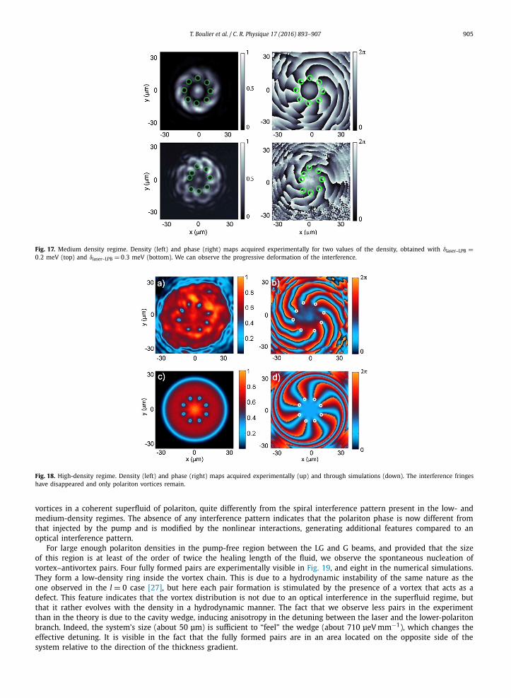
Fig. 17. Medium density regime. Density (left) and phase (right) maps acquired experimentally for two values of the density, obtained with δlaser–LPB =0.2 meV (top) and δlaser–LPB = 0.3 meV (bottom). We can observe the progressive deformation of the interference.
Fig. 18. High-density regime. Density (left) and phase (right) maps acquired experimentally (up) and through simulations (down). The interference fringes have disappeared and only polariton vortices remain.
vortices in a coherent superfluid of polariton, quite differently from the spiral interference pattern present in the low- and medium-density regimes. The absence of any interference pattern indicates that the polariton phase is now different from that injected by the pump and is modified by the nonlinear interactions, generating additional features compared to an optical interference pattern.
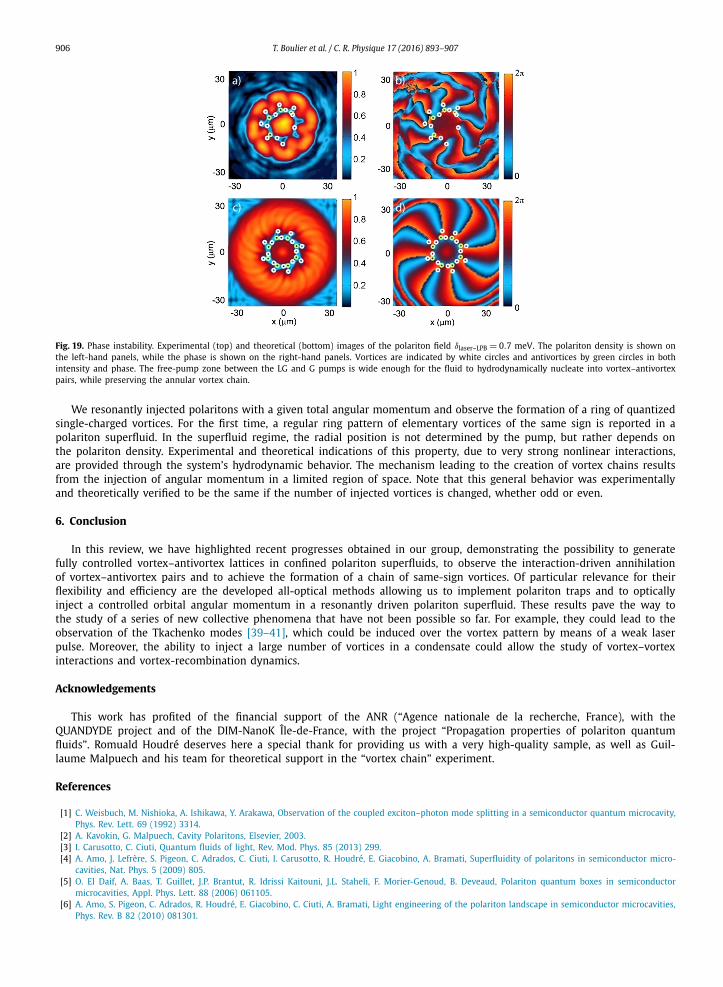
For large enough polariton densities in the pump-free region between the LG and G beams, and provided that the size of this region is at least of the order of twice the healing length of the fluid, we observe the spontaneous nucleation of vortex–antivortex pairs. Four fully formed pairs are experimentally visible in Fig. 19, and eight in the numerical simulations. They form a low-density ring inside the vortex chain. This is due to a hydrodynamic instability of the same nature as the one observed in the l = 0 case [27], but here each pair formation is stimulated by the presence of a vortex that acts as a defect. This feature indicates that the vortex distribution is not due to an optical interference in the superfluid regime, but that it rather evolves with the density in a hydrodynamic manner. The fact that we observe less pairs in the experiment than in the theory is due to the cavity wedge, inducing anisotropy in the detuning between the laser and the lower-polariton branch. Indeed, the system’s size (about 50 μm) is sufficient to “feel” the wedge (about 710 μeV mm−1), which changes the effective detuning. It is visible in the fact that the fully formed pairs are in an area located on the opposite side of the system relative to the direction of the thickness gradient.
906 T. Boulier et al. / C. R. Physique 17 (2016) 893–907
Fig. 19. Phase instability. Experimental (top) and theoretical (bottom) images of the polariton field δlaser–LPB = 0.7 meV. The polariton density is shown on the left-hand panels, while the phase is shown on the right-hand panels. Vortices are indicated by white circles and antivortices by green circles in both intensity and phase. The free-pump zone between the LG and G pumps is wide enough for the fluid to hydrodynamically nucleate into vortex–antivortex pairs, while preserving the annular vortex chain.
We resonantly injected polaritons with a given total angular momentum and observe the formation of a ring of quantized single-charged vortices. For the first time, a regular ring pattern of elementary vortices of the same sign is reported in a polariton superfluid. In the superfluid regime, the radial position is not determined by the pump, but rather depends on the polariton density. Experimental and theoretical indications of this property, due to very strong nonlinear interactions, are provided through the system’s hydrodynamic behavior. The mechanism leading to the creation of vortex chains results from the injection of angular momentum in a limited region of space. Note that this general behavior was experimentally and theoretically verified to be the same if the number of injected vortices is changed, whether odd or even.
6. Conclusion
In this review, we have highlighted recent progresses obtained in our group, demonstrating the possibility to generate fully controlled vortex–antivortex lattices in confined polariton superfluids, to observe the interaction-driven annihilation of vortex–antivortex pairs and to achieve the formation of a chain of same-sign vortices. Of particular relevance for their flexibility and efficiency are the developed all-optical methods allowing us to implement polariton traps and to optically inject a controlled orbital angular momentum in a resonantly driven polariton superfluid. These results pave the way to the study of a series of new collective phenomena that have not been possible so far. For example, they could lead to the observation of the Tkachenko modes [39–41], which could be induced over the vortex pattern by means of a weak laser pulse. Moreover, the ability to inject a large number of vortices in a condensate could allow the study of vortex–vortex interactions and vortex-recombination dynamics.
Acknowledgements
This work has profited of the financial support of the ANR (“Agence nationale de la recherche, France), with the QUANDYDE project and of the DIM-NanoK Île-de-France, with the project “Propagation properties of polariton quantum fluids”. Romuald Houdré deserves here a special thank for providing us with a very high-quality sample, as well as Guil-laume Malpuech and his team for theoretical support in the “vortex chain” experiment.
References
[1] C. Weisbuch, M. Nishioka, A. Ishikawa, Y. Arakawa, Observation of the coupled exciton–photon mode splitting in a semiconductor quantum microcavity, Phys. Rev. Lett. 69 (1992) 3314.
[2] A. Kavokin, G. Malpuech, Cavity Polaritons, Elsevier, 2003.[3] I. Carusotto, C. Ciuti, Quantum fluids of light, Rev. Mod. Phys. 85 (2013) 299.[4] A. Amo, J. Lefrère, S. Pigeon, C. Adrados, C. Ciuti, I. Carusotto, R. Houdré, E. Giacobino, A. Bramati, Superfluidity of polaritons in semiconductor micro-
cavities, Nat. Phys. 5 (2009) 805.[5] O. El Daif, A. Baas, T. Guillet, J.P. Brantut, R. Idrissi Kaitouni, J.L. Staheli, F. Morier-Genoud, B. Deveaud, Polariton quantum boxes in semiconductor
microcavities, Appl. Phys. Lett. 88 (2006) 061105.[6] A. Amo, S. Pigeon, C. Adrados, R. Houdré, E. Giacobino, C. Ciuti, A. Bramati, Light engineering of the polariton landscape in semiconductor microcavities,
Phys. Rev. B 82 (2010) 081301.
T. Boulier et al. / C. R. Physique 17 (2016) 893–907 907
[7] E. Wertz, L. Ferrier, D.D. Solnyshkov, R. Johne, D. Sanvitto, A. Lemaitre, I. Sagnes, R. Grousson, A.V. Kavokin, P. Senellart, G. Malpuech, J. Bloch, Sponta-neous formation and optical manipulation of extended polariton condensates, Nat. Phys. 6 (2010) 860.
[8] J. Kasprzak, M. Richard, S. Kundermann, A. Baas, P. Jeambrun, J.M.J. Keeling, F.M. Marchetti, M.H. Szymanska, R. André, J.L. Staehli, V. Savona, P.B. Littlewood, B. Deveaud, D. Le Si Dang, Bose–Einstein condensation of exciton polaritons, Nature 443 (2006) 409.
[9] A. Amo, S. Pigeon, D. Sanvitto, V.G. Sala, R. Hivet, I. Carusotto, F. Pisanello, G. Leménager, R. Houdré, E. Giacobino, C. Ciuti, A. Bramati, Polariton superfluids reveal quantum hydrodynamic solitons, Science 332 (2011) 1167.
[10] G. Grosso, G. Nardin, F. Morier-Genoud, Y. Léger, B. Deveaud-Plédran, Soliton instabilities and vortex street formation in a polariton quantum fluid, Phys. Rev. Lett. 107 (2011) 245301.
[11] M. Sich, D.N. Krizhanovskii, M.S. Skolnick, Andriy V. Gorbach, Robin Hartley, Dmitry V. Skryabin, E.A. Cerda-Méndez, K. Biermann, R. Hey, P.V. Santos, Observation of bright polariton solitons in a semiconductor microcavity, Nat. Photonics 6 (2012) 50.
[12] J. Keeling, N.G. Berloff, Spontaneous rotating vortex lattices in a pumped decaying condensate, Phys. Rev. Lett. 100 (2008) 250401.[13] K.G. Lagoudakis, M. Wouters, M. Richard, A. Baas, I. Carusotto, R. André, D. Le Si Dang, B. Deveaud-Plédran, Quantized vortices in an exciton–polariton
condensate, Nat. Phys. 4 (2008) 706.[14] G. Nardin, G. Grosso, Y. Léger, B. Pietka, F. Morier-Genoud, B. Deveaud-Plédran, Hydrodynamic nucleation of quantized vortex pairs in a polariton
quantum fluid, Nat. Phys. 7 (8) (2011) 635.[15] D. Sanvitto, S. Pigeon, A. Amo, D. Ballarini, M. De Giorgi, I. Carusotto, R. Hivet, F. Pisanello, V.G. Sala, P.S.S. Guimaraes, R. Houdré, E. Giacobino, C. Ciuti,
A. Bramati, G. Gigli, All-optical control of the quantum flow of a polariton condensate, Nat. Photonics 5 (2011) 610.[16] D. Sanvitto, F.M. Marchetti, M.H. Szymanska, G. Tosi, M. Baudisch, F.P. Laussy, D.N. Krizhanovskii, M.S. Skolnick, L. Marrucci, A. Lemaitre, J. Bloch, C.
Tejedor, L. Vina, Persistent currents and quantized vortices in a polariton fluid, Nat. Phys. 6 (2010) 527.[17] F.M. Marchetti, M.H. Szymanska, C. Tejedor, D.M. Whittaker, Spontaneous and triggered vortices in polariton-optical parametric oscillator superfluids,
Phys. Rev. Lett. 105 (2010) 063902.[18] R. Hivet, E. Cancellieri, T. Boulier, D. Ballarini, D. Sanvitto, F.M. Marchetti, M.H. Szymanska, C. Ciuti, E. Giacobino, A. Bramati, Interaction-shaped vortex–
antivortex lattices in polariton fluids, Phys. Rev. B 89 (2014) 134501.[19] E. Cancellieri, T. Boulier, R. Hivet, D. Ballarini, D. Sanvitto, M.H. Szymanska, C. Ciuti, E. Giacobino, A. Bramati, Merging of vortices and antivortices in
polariton superfluids, Phys. Rev. B 90 (2014) 214518.[20] T. Boulier, H. Terças, D.D. Solnyshkov, Q. Glorieux, E. Giacobino, G. Malpuech, A. Bramati, Vortex chain in a resonantly pumped polariton superfluid, Sci.
Rep. 5 (2015) 9230.[21] R. Houdré, C. Weisbuch, R.P. Stanley, U. Oesterle, M. Ilegems, Coherence effects in light scattering of two-dimensional photonic disordered systems:
elastic scattering of cavity polariton, Phys. Rev. B 61 (2000) R13333.[22] R. Houdré, C. Weisbuch, R.P. Stanley, U. Oesterle, M. Ilegems, Nonlinear emission of semiconductor microcavities in the strong coupling regime, Phys.
Rev. Lett. 85 (2793) (2000) 29.[23] A. Amo, D. Sanvitto, F.P. Laussy, D. Ballarini, E. Del Valle, M.D. Martin, A. Lemaitre, J. Bloch, D.N. Krizhanovskii, M.S. Skolnick, L. Vina, Collective fluid
dynamics of a polariton condensate in a semiconductor microcavity, Nature 457 (2009) 291.[24] M. Sich, D.N. Krizhanovskii, M.S. Skolnick, Andriy V. Gorbach, Robin Hartley, Dmitry V. Skryabin, E.A. Cerda-Méndez, K. Biermann, R. Hey, P.V. Santos,
Observation of bright polariton solitons in a semiconductor microcavity, Nat. Photonics 6 (2012) 50.[25] M.D. Fraser, G. Roumpos, Y. Yamamoto, Vortex–antivortex pair dynamics in an exciton–polariton condensate, New J. Phys. 11 (2009) 113048.[26] G. Roumpos, M.D. Fraser, A. Löffler, S. Höfling, A. Forchel, Y. Yamamoto, Single vortex–antivortex pair in an exciton–polariton condensate, Nat. Phys. 7
(2011) 129.[27] F. Manni, T.C.H. Liew, K.G. Lagoudakis, C. Ouellet-Plamondon, R. André, V. Savona, B. Deveaud, Spontaneous self-ordered states of vortex–antivortex
pairs in a polariton condensate, Phys. Rev. B 88 (2013) 201303.[28] K.G. Lagoudakis, F. Manni, B. Pietka, M. Wouters, T.C.H. Liew, V. Savona, A.V. Kavokin, R. André, B. Deveaud-Plédran, Probing the dynamics of sponta-
neous quantum vortices in polariton superfluids, Phys. Rev. Lett. 106 (2011) 115301.[29] L. Dominici, J.M. Fellows, S. Donati, D. Ballarini, M. De Giorgi, F.M. Marchetti, B. Piccirillo, L. Marrucci, A. Bramati, G. Gigli, Vortex and half-vortex
dynamics in a nonlinear spinor quantum fluid, Sci. Adv. 1 (2015) e1500807, http://dx.doi.org/10.1126/sciadv.1500807.[30] S. Pigeon, I. Carusotto, C. Ciuti, Hydrodynamic nucleation of vortices and solitons in a resonantly excited polariton superfluid, Phys. Rev. B 83 (2011)
144513.[31] G. Tosi, G. Christmann, N.G. Berloff, P. Tsotsis, T. Gao, Z. Hatzopoulos, P.G. Savvidis, J.J. Baumberg, Geometrically locked vortex lattices in semiconductor
quantum fluids, Nat. Commun. 3 (2012) 1243.[32] A. Amo, T.C.H. Liew, C. Adrados, R. Houdré, E. Giacobino, A.V. Kavokin, A. Bramati, Exciton–polariton spin switches, Nat. Photonics 4 (2010) 361.[33] P. Cristofolini, A. Dreismann, G. Christmann, G. Franchetti, N.G. Berloff, P. Tsotsis, Z. Hatzopoulos, P.G. Savvidis, J.J. Baumberg, Optical superfluid phase
transitions and trapping of polariton condensates, Phys. Rev. Lett. 110 (2013) 186403.[34] A. Dreismann, P. Cristofolini, R. Balili, G. Christmann, F. Pinsker, N.G. Berloff, Z. Hatzopoulos, P.G. Savvidis, J.J. Baumberg, Coupled counter-rotating
polariton condensates in optically defined annular potentials, Proc. Natl. Acad. Sci. USA 111 (2014) 8770–8775.[35] T.C.H. Liew, Y.G. Rubo, A.V. Kavokin, Phys. Rev. Lett. 101 (2008) 187401.[36] A.V. Gorbach, R. Hartley, D.V. Skryabin, Phys. Rev. Lett. 104 (2010) 213903.[37] M.O. Borgh, G. Franchetti, J. Keeling, N.G. Berloff, Robustness and observability of rotating vortex lattices in an exciton–polariton condensate, Phys. Rev.
B 86 (2012) 035307.[38] J.O. Hamp, A.K. Balin, F.M. Marchetti, D. Sanvitto, M.H. Szymanska, Spontaneous vortex arrays in a parametrically driven polariton condensate, Europhys.
Lett. 110 (2015) 57006.[39] A.L. Fetter, Rotating trapped Bose–Einstein condensates, Rev. Mod. Phys. 81 (2009) 647.[40] E.B. Sonin, Continuum theory of Tkachenko modes in rotating Bose–Einstein condensates, Phys. Rev. A 71 (2005) 011603.[41] Coddington, P. Engels, V. Schweikhard, E.A. Cornell, Observation of Tkachenko oscillations in rapidly rotating Bose–Einstein condensates, Phys. Rev. Lett.
91 (2003) 100402.