Embed Size (px)
Citation preview
2
AVERTISSEMENT
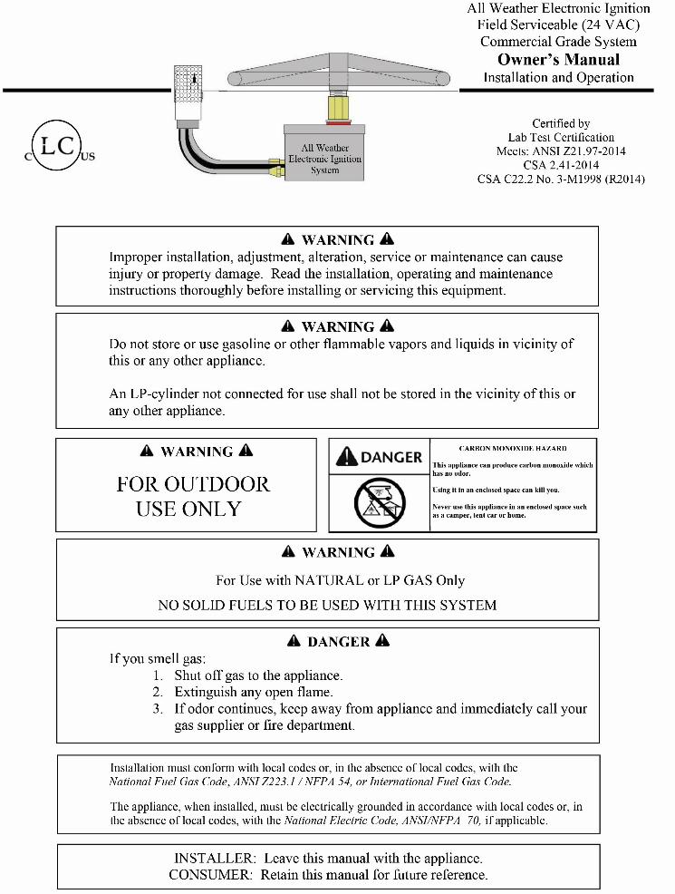
Une installation, un ajustement, une modification, une réparation ou un entretien inapproprié peuvent être la cause de blessures ou de dommages. Veuillez lire attentivement les instructions d'installation, d'utilisation et d'entretien avant d'installer ou de réparer ce matériel.
AVERTISSEMENT
Ne pas entreposer ni utiliser de l'essence ni d'autres vapeurs ou liquides inflammables dans le voisinage de l'appareil, ni de tout autre appareil.
Une bouteille de propane qui n'est pas raccordée en vue de son utilisation, ne doit pas être entreposée dans le voisinage de cet appareil ou de tout autre appareil.
DANGER
S'il y a une odeur de gaz: 1. Coupez l'admission de gaz de l'appariel. 2. Éteindre toute flamme nue. 3. Si l'odeur persiste, éloignez-vous de l'appareil et appelez immédiatement le fournisseur de gaz ou le service d'incendie.
AVERTISSEMENT
Pour utilisation avec naturel ou propane ne gaz seulement
Aucun combustibles solides pour être utilisés avec ce système
MONOXYDE DE CARBONE
Cet appareil peut produire dumonoxyde de
carbone, un gaz inodore.
L’utililisation de cet appareil dans des espases clos
peut entrainer la mort.
Ne jamais utilizer cet appareil dans un espace clos
comme un vehicule de damping, une tente, une
automobile ou une maison.
AVERTISSEMENT
Pour utilisation à l'extérieur seulement.
AVERTISSEMENT
Ne pas utiliser cet appareil s'il a été plongé, même partiellement, dans l'eau. Appeler un technicien qualifié pour inspecter l'appareil et remplacer toute partie du système de commande et toute commande qui a été plongée dans l'eau.
Proposition 65 Warning
Operating, servicing and maintaining this appliance can expose you to chemicals including
Carbon Monoxide and Lead which are known to the State of California to cause cancer, birth
defects or other reproductive harm. For more information go to www.Prop65Warnings.ca.gov

3
Table of Contents
Pilot Burner
Assembly
LP Air Mixer
(LP applications only)
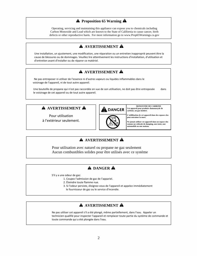
Gas and Electrical Requirements Page 4
Daisy Chain Wiring Requirement Page 4
Clearances Page 5
Installation Page 5
Acceptable Media for Fire Features Page 8
Installation of Media in Fire Features Page 8
Operation Page 9
Maintenance Page 10
Replacement Parts Page 11
Troubleshooting Page 11
Attachment 1: Automated Pool Controller Wiring Illustration Page 12
5
Installation
Installation
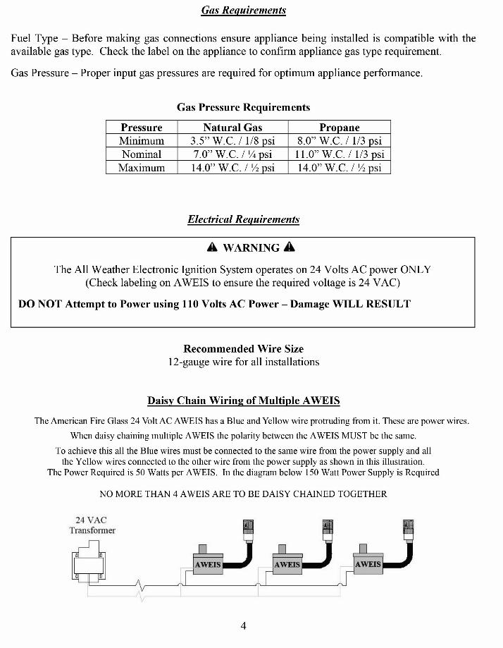
Note: Installation should be done by a qualified service technician that is locally licensed.
1. In the photo at right there is a bowl with both a gas
riser and an electrical conduit stubbed up inside the bowl.
It is preferred to stub the gas riser centered in order to
ensure the fire ring is centered in the bowl once
installation is complete.
NOTE: Drainage MUST be provided in the bowl.
Drainage can be obtained by making holes in the bottom
or sides of the bowl as shown.
2. Apply pipe dope/tape to the gas stub and thread the
AWEIS Ignition Control Box onto the gas riser as shown
in the photo at right.
NOTE: Leak Test – it is highly recommended to perform
a gas leak test at this point in the install. Turn on the gas
supply and then, using a soapy water solution spray the
bottom of the AWEIS where it is connected to the gas line
to ensure no leaks exist.
3. Electrical Connections. In the photo at right the wires
protruding from the AWEIS have been connected to the
two wires from the electrical conduit using appropriate
sized wire nuts.
NOTE: It is not required but it is recommended to fill
the wire nuts with either dielectric grease or silicone prior
to installing the wire nut. This will ensure a weatherproof
electrical connection.
Drain Hole
in Bottom
Gas Stub
Electrical
Conduit
Drain Hole
in Side
Clearances
WARNING – FIRE RISK
8 ft.
36 in.
2 in.
Clearance from Combustibles Main Burner Clearances
Min. 6” Clearance
Max. 3” Below
Top of Bowl
6
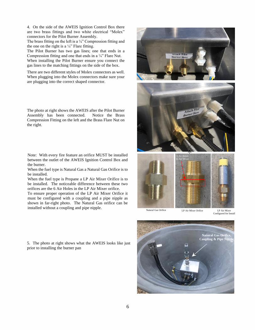
4. On the side of the AWEIS Ignition Control Box there
are two brass fittings and two white electrical “Molex”
connectors for the Pilot Burner Assembly.
The brass fitting on the left is a ¼” Compression fitting and
the one on the right is a ¼” Flare fitting.
The Pilot Burner has two gas lines; one that ends in a
Compression fitting and one that ends in a ¼” Flare Nut.
When installing the Pilot Burner ensure you connect the
gas lines to the matching fittings on the side of the box.
There are two different styles of Molex connectors as well.
When plugging into the Molex connectors make sure your
are plugging into the correct shaped connector.
The photo at right shows the AWEIS after the Pilot Burner
Assembly has been connected. Notice the Brass
Compression Fitting on the left and the Brass Flare Nut on
the right.
5. The photo at right shows what the AWEIS looks like just
prior to installing the burner pan
Natural Gas Orifice LP Air Mixer Orifice LP Air Mixer
Configured for Install
6 Air Holes
In Air Mixer
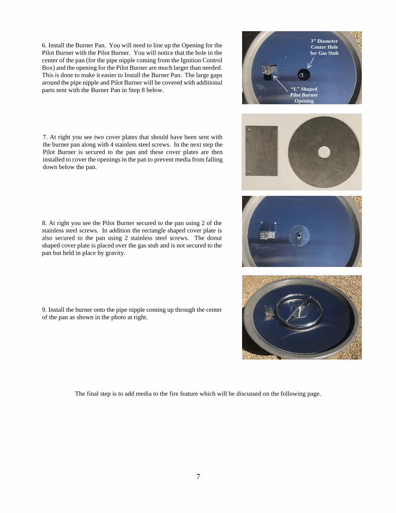
Note: With every fire feature an orifice MUST be installed
between the outlet of the AWEIS Ignition Control Box and
the burner.
When the fuel type is Natural Gas a Natural Gas Orifice is to
be installed.
When the fuel type is Propane a LP Air Mixer Orifice is to
be installed. The noticeable difference between these two
orifices are the 6 Air Holes in the LP Air Mixer orifice.
To ensure proper operation of the LP Air Mixer Orifice it
must be configured with a coupling and a pipe nipple as
shown in far-right photo. The Natural Gas orifice can be
installed without a coupling and pipe nipple.
Natural Gas Orifice,
Coupling & Pipe Nipple
7
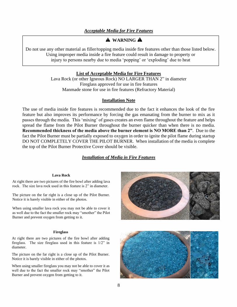
6. Install the Burner Pan. You will need to line up the Opening for the
Pilot Burner with the Pilot Burner. You will notice that the hole in the
center of the pan (for the pipe nipple coming from the Ignition Control
Box) and the opening for the Pilot Burner are much larger than needed.
This is done to make it easier to Install the Burner Pan. The large gaps
around the pipe nipple and Pilot Burner will be covered with additional
parts sent with the Burner Pan in Step 8 below.
7. At right you see two cover plates that should have been sent with
the burner pan along with 4 stainless steel screws. In the next step the
Pilot Burner is secured to the pan and these cover plates are then
installed to cover the openings in the pan to prevent media from falling
down below the pan.
8. At right you see the Pilot Burner secured to the pan using 2 of the
stainless steel screws. In addition the rectangle shaped cover plate is
also secured to the pan using 2 stainless steel screws. The donut
shaped cover plate is placed over the gas stub and is not secured to the
pan but held in place by gravity.
9. Install the burner onto the pipe nipple coming up through the center
of the pan as shown in the photo at right.
“L” Shaped
Pilot Burner
Opening
3” Diameter
Center Hole
for Gas Stub
The final step is to add media to the fire feature which will be discussed on the following page.
8
Acceptable Media for Fire Features
List of Acceptable Media for Fire Features
Lava Rock (or other Igneous Rock) NO LARGER THAN 2” in diameter
Fireglass approved for use in fire features
Manmade stone for use in fire features (Refractory Material)
Installation Note
The use of media inside fire features is recommended due to the fact it enhances the look of the fire
feature but also improves its performance by forcing the gas emanating from the burner to mix as it
passes through the media. This ‘mixing’ of gases creates an even flame throughout the feature and helps
spread the flame from the Pilot Burner throughout the burner quicker than when there is no media.
Recommended thickness of the media above the burner element is NO MORE than 2”. Due to the
fact the Pilot Burner must be partially exposed to oxygen in order to ignite the pilot flame during startup
DO NOT COMPLETELY COVER THE PILOT BURNER. When installation of the media is complete
the top of the Pilot Burner Protective Cover should be visible.
Installation of Media in Fire Features
Lava Rock
At right there are two pictures of the fire bowl after adding lava
rock. The size lava rock used in this feature is 2” in diameter.
The picture on the far right is a close up of the Pilot Burner.
Notice it is barely visible in either of the photos.
When using smaller lava rock you may not be able to cover it
as well due to the fact the smaller rock may “smother” the Pilot
Burner and prevent oxygen from getting to it.
WARNING
Do not use any other material as filler/topping media inside fire features other than those listed below.
Using improper media inside a fire feature could result in damage to property or
injury to persons nearby due to media ‘popping’ or ‘exploding’ due to heat
1” above ring
Fireglass
At right there are two pictures of the fire bowl after adding
fireglass. The size fireglass used in this feature is 1/2” in
diameter.
The picture on the far right is a close up of the Pilot Burner.
Notice it is barely visible in either of the photos.
When using smaller fireglass you may not be able to cover it as
well due to the fact the smaller rock may “smother” the Pilot
Burner and prevent oxygen from getting to it.
9
Illustrations showing Completed Installations
Operation
Fire Feature Start Up
1. Prior to turning appliance on visually inspect fire feature to ensure debris such as leaves or other
combustible material has not collected inside the feature which could burn and emit embers once the
fire feature is turned on. Also ensure any person standing close to the fire feature is aware you will be
turning the fire feature on prior to actually turning it on.
WARNING
Do NOT use this appliance if any part has been under water.
Immediately call a qualified service technician to inspect the appliance and to replace
any part of the control system and any gas control which has been under water.
WARNING
HOT – DO NOT TOUCH - SEVERE BURNS MAY RESULT - CLOTHING IGNITION MAY RESULT
- CAREFULLY SUPERVISE children in same area as the appliance.
- Alert children and adults to hazards of high temperatures.
- Clothing or other flammable materials should not be hung from the appliance or placed on or near the
appliance.
WARNING
The appliance should be inspected before use and at least annually by a qualified service technician.
Any guard or protective device removed for servicing must be replaced prior to operation.
Keep the appliance area clear and free from combustible materials, gasoline and other flammable vapors and liquids.
Pilot Burner
Assembly
24 vac
Power
Electrical
Conduit Gas
Line
Illustration of Properly Installed AWEIS
(Natural Gas)
Natural Gas Orifice
Fire Ring / Burner
(Holes Facing Up) Pilot Burner
Assembly
Burner Pan
24 vac
Power
Drain Hole
Electrical
Conduit
Illustration of Properly Installed AWEIS
(Propane)
Gas
Line
Ignition
Control Box
Air Mixer
Drain Hole
Coupling
Fire Ring / Burner
(Holes Facing Up)
Burner Pan
Drain Hole Drain Hole
Ignition
Control Box
10
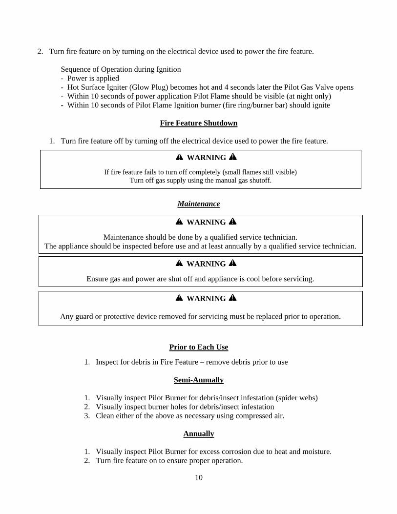
2. Turn fire feature on by turning on the electrical device used to power the fire feature.
Sequence of Operation during Ignition
- Power is applied
- Hot Surface Igniter (Glow Plug) becomes hot and 4 seconds later the Pilot Gas Valve opens
- Within 10 seconds of power application Pilot Flame should be visible (at night only)
- Within 10 seconds of Pilot Flame Ignition burner (fire ring/burner bar) should ignite
Fire Feature Shutdown
1. Turn fire feature off by turning off the electrical device used to power the fire feature.
Maintenance
Prior to Each Use
1. Inspect for debris in Fire Feature – remove debris prior to use
Semi-Annually
1. Visually inspect Pilot Burner for debris/insect infestation (spider webs)
2. Visually inspect burner holes for debris/insect infestation
3. Clean either of the above as necessary using compressed air.
Annually
1. Visually inspect Pilot Burner for excess corrosion due to heat and moisture.
2. Turn fire feature on to ensure proper operation.
WARNING
Maintenance should be done by a qualified service technician.
The appliance should be inspected before use and at least annually by a qualified service technician.
WARNING
Ensure gas and power are shut off and appliance is cool before servicing.
WARNING
Any guard or protective device removed for servicing must be replaced prior to operation.
WARNING
If fire feature fails to turn off completely (small flames still visible)
Turn off gas supply using the manual gas shutoff.
11
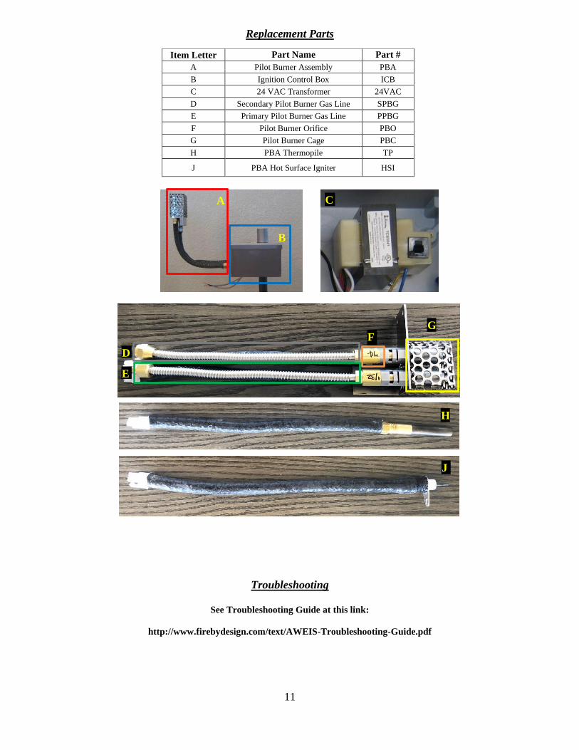
Troubleshooting
See Troubleshooting Guide at this link:
http://www.firebydesign.com/text/AWEIS-Troubleshooting-Guide.pdf
Item Letter Part Name Part #
A Pilot Burner Assembly PBA
B Ignition Control Box ICB
C 24 VAC Transformer 24VAC
D Secondary Pilot Burner Gas Line SPBG
E Primary Pilot Burner Gas Line PPBG
F Pilot Burner Orifice PBO
G Pilot Burner Cage PBC
H PBA Thermopile TP
J PBA Hot Surface Igniter HSI
Replacement Parts
A
B
C
G F
D
E
H
J
12
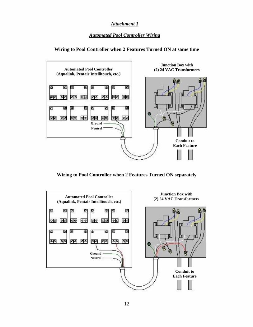
Wiring to Pool Controller when 2 Features Turned ON separately
Note: In order to Turn on 2 or more Features ON separately EACH feature
Requires its own 30 VDC Power Supply. One 30 VDC Power Supply is shown above
Attachment 1
Automated Pool Controller Wiring
Wiring to Pool Controller when 2 Features Turned ON at same time
Automated Pool Controller
(Aqualink, Pentair Intellitouch, etc.)
Automated Pool Controller
(Aqualink, Pentair Intellitouch, etc.)
Junction Box with
(2) 24 VAC Transformers
Junction Box with
(2) 24 VAC Transformers
Conduit to
Each Feature
Conduit to
Each Feature
Wiring to Pool Controller when 2 Features Turned ON separately
Ground
Ground
Neutral
Neutral


![Structural Importance of Stone-Thrower-Wales Defects in Rolled … · 2019. 5. 11. · dicyclopenta[ef,kl]heptalene (azupyrene), whose molecule consists of two 5-7 pairs terminated](https://img.pdfslide.fr/doc/110x75/60dc03f77d7052324428d121/structural-importance-of-stone-thrower-wales-defects-in-rolled-2019-5-11-dicyclopentaefklheptalene.jpg)