Embed Size (px)
Citation preview
International Journal of Computer Applications (0975 – 8887)
International Conference on Communication Technology 2013
19
Dual Band Shorted Rectangular Microstrip Antenna
Amit A. Deshmukh
EXTC, DJSCOE Vile – Parle Mumbai, India
Tejal A. Tirodkar
EXTC, DJSCOE Vile – Parle
Mumbai, India
Aswathi K.
EXTC, DJSCOE,
Nada K.,
EXTC, DJSCOE
Prithvi K.
EXTC, DJSCOE
ABSTRACT
The compact rectangular microstrip antenna is realized by
placing the shorting post or plate along the zero field line at
the fundamental mode of the patch. The dual band antenna is
realized by placing the stub on the edges of the patch. In this
paper, first a compact shorted rectangular microstrip antenna
is discussed. Further a dual band antenna realized by placing
the stub on the opposite edge of the shorted rectangular patch,
is proposed. The analysis to study the effects of stub on the
dual band response in stub loaded antenna is presented. The
stub reduces the resonance frequency of second order TM3/4,0
mode of the shorted patch and along with the fundamental
TM1/4,0 mode yields dual frequency response. Further by
studying the surface current distribution at the fundamental
and higher order modes, the formulation in resonant length is
proposed. The frequencies calculated using them agrees
closely with simulated results with a % error less than 5%
over the complete stub length range.
Keywords
Rectangular microstrip antenna, Shorted rectangular
microstrip antenna, Compact microstrip antenna, Open circuit
stub, Higher order mode
1. INTRODUCTION With the advent of personal mobile communication the need
for compact antenna has increased. The microstrip antenna
(MSA) has been used in many of such applications. The more
common techniques to realize compact MSA is by placing the
shorting post or plate along the zero field line at the
fundamental patch mode or by cutting the slot at an
appropriate position inside the patch [1 – 3]. The shorting
method converts the conventional half wave length resonator
into quarter wavelength resonator whereas the slot increases
surface current length for the given mode, thereby reducing its
resonance frequency. Further dual band MSA is realized by
cutting the slot inside the patch or by placing an open circuit
stub of nearly quarter wave in length on the edges of the patch
[4 – 8]. The stub is said to offer capacitive and inductive
impedance around the resonance frequency of the patch to
realize dual frequencies. To get an insight into the functioning
of stub loaded MSAs, an analysis for varying stub length in
dual band MSAs has been carried out [9]. The stub reduces
the resonance frequency of orthogonal higher order mode of
the patch and along with the fundamental patch mode yields
dual band response. The stub also modifies the surface current
directions at higher order mode and thereby gives broadside
radiation pattern at the dual frequencies.
In this paper, first fundamental and higher order modes of the
rectangular MSA (RMSA) and shorted RMSA for different
feed point locations are discussed. All the modes which are
present in the conventional RMSA are not present in the
shorted patch as the impedance matching at them is not
realized. Further a dual band stub loaded shorted RMSA is
proposed. An analysis to study the effects of stub length on
the dual band response is presented. The stub reduces the
resonance frequencies of fundamental and higher order modes
of the shorted RMSA and realizes dual frequency response.
Since the shorted patch is used, the radiation pattern at the two
frequencies is maximum in end-fire direction. Further by
studying the surface current distribution at the dual
frequencies, a formulation in resonant length is proposed. The
frequencies calculated using them agrees closely with the
simulated results obtained using IE3D software which agrees
closely with the measured results [10]. The proposed analysis
is carried out using glass epoxy substrate (h = 0.16 cm, r =
4.3, tan = 0.02). The antenna is fed using the coaxial probe
of 0.12 cm inner wire diameter and the measurement of
optimized dual band antenna was carried out using R & S
vector network analyzer.
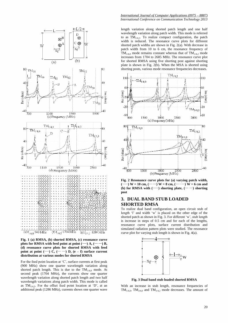
2. RMSA and Shorted RMSA The RMSA on glass epoxy substrate operating in its
fundamental TM10 mode is shown in Fig. 1(a). Using the
reported resonance frequency equation, the patch length ‘L’ is
calculated such that it operates in TM10 mode at frequency of
around 900 MHz. The patch width ‘W’ is taken to be more
than its length. Around 900 MHz, the patch dimensions are, L
= 8.0 cm and W = 10.0 cm. For feed point at location ‘A’,
RMSA is simulated using IE3D software and its resonance
curve plot is shown in Fig. 1(c). The plot shows peaks due to
TM10 (892 MHz), TM02 (1436 MHz), TM12 (1713 MHz) and
TM20 (1779 MHz) modes. The RMSA was simulated for
offset feed point location ‘B’ as shown in Fig. 1(a) and its
resonance curve plot is shown in Fig. 1(c). The plot shows
additional peaks due to TM01 (720 MHz), TM11 (1161 MHz)
and TM21 (1927 MHz) modes. At TM10 mode the RMSA
shows zero field in the center. The compact RMSA is realized
by placing the shorting plate along this zero field line as
shown in Fig. 1(b). The shorted RMSA is a quarter
wavelength resonator as against RMSA which is half
wavelength resonator. It is simulated for two different feed
point locations as shown in Fig. 1(b). The resonance curve
plots for them are shown in Fig. 1(d). The surface current
distribution at two peaks for feed point location ‘C’ and
additional peak for feed point location at point ‘D’ are shown
in Fig. 1(e – g).
International Journal of Computer Applications (0975 – 8887)
International Conference on Communication Technology 2013
20
Fig. 1 (a) RMSA, (b) shorted RMSA, (c) resonance curve
plots for RMSA with feed point at point (____) A, (___ ___) B,
(d) resonance curve plots for shorted RMSA with feed
point at point (____) C, (___ ___) D, (e – f) surface current
distribution at various modes for shorted RMSA
For the feed point location at ‘C’, surface currents at first peak
(900 MHz) show one quarter wavelength variation along
shorted patch length. This is due to the TM1/4,0 mode. At
second peak (1704 MHz), the currents show one quarter
wavelength variation along shorted patch length and two half
wavelength variations along patch width. This mode is called
as TM1/4,2. For the offset feed point location at ‘D’, at an
additional peak (1286 MHz), currents shows one quarter wave
length variation along shorted patch length and one half
wavelength variation along patch width. This mode is referred
to as TM1/4,1. To realize compact configuration, the patch
width is reduced. The resonance curve plots for different
shorted patch widths are shown in Fig. 2(a). With decrease in
patch width from 10 to 6 cm, the resonance frequency of
TM1/4,0 mode remains constant whereas that of TM1/4,2 mode
increases from 1704 to 2685 MHz. The resonance curve plot
for shorted RMSA using five shorting post against shorting
plate is shown in Fig. 2(b). When the MSA is shorted using
shorting posts, various mode resonance frequencies decreases.
Fig. 2 Resonance curve plots for (a) varying patch width,
(_____) W = 10 cm, (___ ___) W = 8 cm, (___ _ ___) W = 6 cm and
(b) for RMSA with (_____) shorting plate, (___ ___) shorting
post
3. DUAL BAND STUB LOADED
SHORTED RMSA To realize dual band configuration, an open circuit stub of
length ‘l’ and width ‘w’ is placed on the other edge of the
shorted patch as shown in Fig. 3. For different ‘w’, stub length
is increase in steps of 0.5 cm and for each of the lengths,
resonance curve plots, surface current distribution and
simulated radiation pattern plots were studied. The resonance
curve plot for varying stub length is shown in Fig. 4(a).
Fig. 3 Dual band stub loaded shorted RMSA
With an increase in stub length, resonance frequencies of
TM1/4,0, TM3/4,0 and TM1/4,2 mode decreases. The amount of
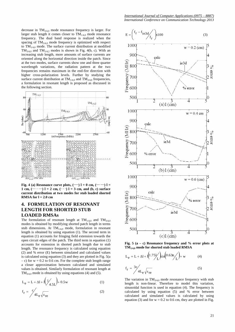
International Journal of Computer Applications (0975 – 8887)
International Conference on Communication Technology 2013
21
decrease in TM3/4,0 mode resonance frequency is larger. For
larger stub length it comes closer to TM1/4,0 mode resonance
frequency. The dual band response is realized when the
spacing of TM3/4,0 mode frequency is optimized with respect
to TM1/4,0 mode. The surface current distribution at modified
TM3/4,0 and TM1/4,2 modes is shown in Fig. 4(b, c). With an
increasing stub length, more amounts of surface currents are
oriented along the horizontal direction inside the patch. Since
at the two modes, surface currents show one and three quarter
wavelength variations, the radiation pattern at the two
frequencies remains maximum in the end-fire direction with
higher cross-polarization levels. Further by studying the
surface current distribution at TM1/4,0 and TM3/4,0 frequencies,
a formulation in resonant length is proposed as discussed in
the following section.
Fig. 4 (a) Resonance curve plots, (____) l = 0 cm, (___ ___) l =
1 cm, (___ _ ___) l = 2 cm, (_ _ _) l = 3 cm, and (b, c) surface
current distribution at two modes for stub loaded shorted
RMSA for l = 2.0 cm
4. FORMULATION OF RESONANT
LENGTH FOR SHORTED STUB
LOADED RMSAs The formulation of resonant length at TM1/4,0 and TM3/4,0
modes is obtained by modifying shorted patch length in terms
stub dimensions. At TM1/4,0 mode, formulation in resonant
length is obtained by using equation (1). The second term in
equation (1) accounts for fringing field extension towards the
open circuit edges of the patch. The third term in equation (1)
accounts for extension in shorted patch length due to stub
length. The resonance frequency is calculated using equation
(2) and % error (E) between simulated and calculated values
is calculated using equation (3) and they are plotted in Fig. 5(a
– c) for w = 0.2 to 0.6 cm. For the complete stub length range
a closer approximation between calculated and simulated
values is obtained. Similarly formulation of resonant length at
TM3/4,0 mode is obtained by using equations (4) and (5).
0.5w4.5L
llΔlLeL (1)
reεe4L
crf (2)
x100rf
ie3dfrfE
(3)
Fig. 5 (a – c) Resonance frequency and % error plots at
TM1/4,0 mode for shorted stub loaded RMSA
wL
0.63π.sinL
1.75llΔlLeL (4)
reεe4L
3crf (5)
The variation in TM3/4,0 mode resonance frequency with stub
length is non-linear. Therefore to model this variation,
sinusoidal function is used in equation (4). The frequency is
calculated by using equation (5) and % error between
calculated and simulated values is calculated by using
equation (3) and for w = 0.2 to 0.6 cm, they are plotted in Fig.
International Journal of Computer Applications (0975 – 8887)
International Conference on Communication Technology 2013
22
6(a – c). For the complete stub length range, a good
approximation between calculated and simulated values is
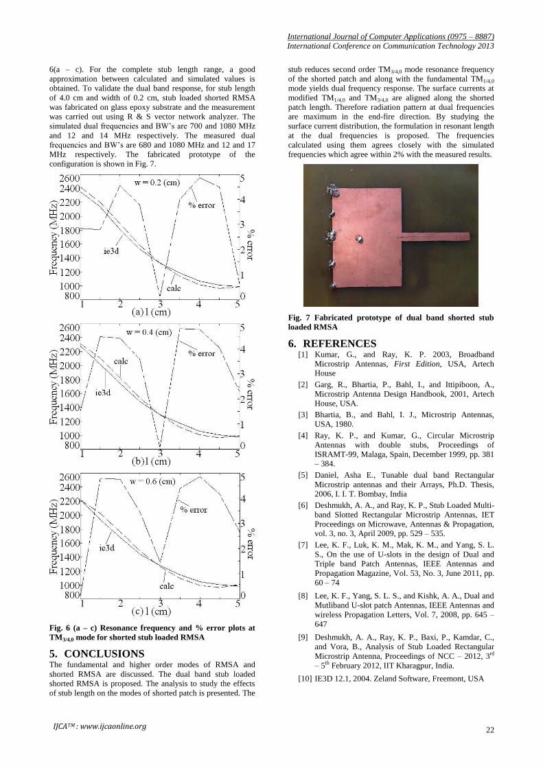
obtained. To validate the dual band response, for stub length
of 4.0 cm and width of 0.2 cm, stub loaded shorted RMSA
was fabricated on glass epoxy substrate and the measurement
was carried out using R & S vector network analyzer. The
simulated dual frequencies and BW’s are 700 and 1080 MHz
and 12 and 14 MHz respectively. The measured dual
frequencies and BW’s are 680 and 1080 MHz and 12 and 17
MHz respectively. The fabricated prototype of the
configuration is shown in Fig. 7.
Fig. 6 (a – c) Resonance frequency and % error plots at
TM3/4,0 mode for shorted stub loaded RMSA
5. CONCLUSIONS The fundamental and higher order modes of RMSA and
shorted RMSA are discussed. The dual band stub loaded
shorted RMSA is proposed. The analysis to study the effects
of stub length on the modes of shorted patch is presented. The
stub reduces second order TM3/4,0 mode resonance frequency
of the shorted patch and along with the fundamental TM1/4,0
mode yields dual frequency response. The surface currents at
modified TM1/4,0 and TM3/4,0 are aligned along the shorted
patch length. Therefore radiation pattern at dual frequencies
are maximum in the end-fire direction. By studying the
surface current distribution, the formulation in resonant length
at the dual frequencies is proposed. The frequencies
calculated using them agrees closely with the simulated
frequencies which agree within 2% with the measured results.
Fig. 7 Fabricated prototype of dual band shorted stub
loaded RMSA
6. REFERENCES [1] Kumar, G., and Ray, K. P. 2003, Broadband
Microstrip Antennas, First Edition, USA, Artech House
[2] Garg, R., Bhartia, P., Bahl, I., and Ittipiboon, A.,
Microstrip Antenna Design Handbook, 2001, Artech
House, USA.
[3] Bhartia, B., and Bahl, I. J., Microstrip Antennas,
USA, 1980.
[4] Ray, K. P., and Kumar, G., Circular Microstrip
Antennas with double stubs, Proceedings of
ISRAMT-99, Malaga, Spain, December 1999, pp. 381 – 384.
[5] Daniel, Asha E., Tunable dual band Rectangular
Microstrip antennas and their Arrays, Ph.D. Thesis,
2006, I. I. T. Bombay, India
[6] Deshmukh, A. A., and Ray, K. P., Stub Loaded Multi-
band Slotted Rectangular Microstrip Antennas, IET
Proceedings on Microwave, Antennas & Propagation, vol. 3, no. 3, April 2009, pp. 529 – 535.
[7] Lee, K. F., Luk, K. M., Mak, K. M., and Yang, S. L.
S., On the use of U-slots in the design of Dual and
Triple band Patch Antennas, IEEE Antennas and
Propagation Magazine, Vol. 53, No. 3, June 2011, pp.
60 – 74
[8] Lee, K. F., Yang, S. L. S., and Kishk, A. A., Dual and
Mutliband U-slot patch Antennas, IEEE Antennas and
wireless Propagation Letters, Vol. 7, 2008, pp. 645 –
647
[9] Deshmukh, A. A., Ray, K. P., Baxi, P., Kamdar, C.,
and Vora, B., Analysis of Stub Loaded Rectangular
Microstrip Antenna, Proceedings of NCC – 2012, 3rd
– 5th February 2012, IIT Kharagpur, India.
[10] IE3D 12.1, 2004. Zeland Software, Freemont, USA
IJCATM : www.ijcaonline.org


![THESE - bu.umc.edu.dz · donde équivalent pour la ligne microstrip [10], Méthode des Lignes [11], et Méthode de la Résonance transverse](https://img.pdfslide.fr/doc/110x75/5b980ca109d3f2e3488cdf7d/these-buumcedudz-donde-equivalent-pour-la-ligne-microstrip-10-methode.jpg)