Embed Size (px)
Citation preview
Pro
vide
d by
: w
ww
.spi
c.ir
IEC 60364-4-43Edition 3.0 2008-08
INTERNATIONAL STANDARD NORME INTERNATIONALE
Low-voltage electrical installations – Part 4-43: Protection for safety – Protection against overcurrent Installations électriques à basse tension – Partie 4-43: Protection pour assurer la sécurité – Protection contre les surintensités
IEC
603
64-4
-43:
2008
GROUP SAFETY PUBLICATION PUBLICATION GROUPÉE DE SÉCURITÉ
Copyright International Electrotechnical Commission Provided by IHS under license with IEC Licensee=Hong Kong Polytechnic Univ/9976803100
Not for Resale, 12/31/2010 02:47:20 MSTNo reproduction or networking permitted without license from IHS
--`,````,,,,,``,,,,,`,`,,`,`,`,`-`-`,,`,,`,`,,`---
Pro
vide
d by
: w
ww
.spi
c.ir
THIS PUBLICATION IS COPYRIGHT PROTECTED Copyright © 2008 IEC, Geneva, Switzerland All rights reserved. Unless otherwise specified, no part of this publication may be reproduced or utilized in any form or by any means, electronic or mechanical, including photocopying and microfilm, without permission in writing from either IEC or IEC's member National Committee in the country of the requester. If you have any questions about IEC copyright or have an enquiry about obtaining additional rights to this publication, please contact the address below or your local IEC member National Committee for further information. Droits de reproduction réservés. Sauf indication contraire, aucune partie de cette publication ne peut être reproduite ni utilisée sous quelque forme que ce soit et par aucun procédé, électronique ou mécanique, y compris la photocopie et les microfilms, sans l'accord écrit de la CEI ou du Comité national de la CEI du pays du demandeur. Si vous avez des questions sur le copyright de la CEI ou si vous désirez obtenir des droits supplémentaires sur cette publication, utilisez les coordonnées ci-après ou contactez le Comité national de la CEI de votre pays de résidence.
IEC Central Office 3, rue de Varembé CH-1211 Geneva 20 Switzerland Email: [email protected] Web: www.iec.ch
About the IEC The International Electrotechnical Commission (IEC) is the leading global organization that prepares and publishes International Standards for all electrical, electronic and related technologies.
About IEC publications The technical content of IEC publications is kept under constant review by the IEC. Please make sure that you have the latest edition, a corrigenda or an amendment might have been published. Catalogue of IEC publications: www.iec.ch/searchpub
The IEC on-line Catalogue enables you to search by a variety of criteria (reference number, text, technical committee,…). It also gives information on projects, withdrawn and replaced publications. IEC Just Published: www.iec.ch/online_news/justpub
Stay up to date on all new IEC publications. Just Published details twice a month all new publications released. Available on-line and also by email. Electropedia: www.electropedia.org
The world's leading online dictionary of electronic and electrical terms containing more than 20 000 terms and definitions in English and French, with equivalent terms in additional languages. Also known as the International Electrotechnical Vocabulary online. Customer Service Centre: www.iec.ch/webstore/custserv
If you wish to give us your feedback on this publication or need further assistance, please visit the Customer Service Centre FAQ or contact us: Email: [email protected] Tel.: +41 22 919 02 11 Fax: +41 22 919 03 00
A propos de la CEI La Commission Electrotechnique Internationale (CEI) est la première organisation mondiale qui élabore et publie des normes internationales pour tout ce qui a trait à l'électricité, à l'électronique et aux technologies apparentées.
A propos des publications CEI Le contenu technique des publications de la CEI est constamment revu. Veuillez vous assurer que vous possédez l’édition la plus récente, un corrigendum ou amendement peut avoir été publié. Catalogue des publications de la CEI: www.iec.ch/searchpub/cur_fut-f.htm
Le Catalogue en-ligne de la CEI vous permet d’effectuer des recherches en utilisant différents critères (numéro de référence, texte, comité d’études,…). Il donne aussi des informations sur les projets et les publications retirées ou remplacées. Just Published CEI: www.iec.ch/online_news/justpub
Restez informé sur les nouvelles publications de la CEI. Just Published détaille deux fois par mois les nouvelles publications parues. Disponible en-ligne et aussi par email. Electropedia: www.electropedia.org
Le premier dictionnaire en ligne au monde de termes électroniques et électriques. Il contient plus de 20 000 termes et définitions en anglais et en français, ainsi que les termes équivalents dans les langues additionnelles. Egalement appelé Vocabulaire Electrotechnique International en ligne. Service Clients: www.iec.ch/webstore/custserv/custserv_entry-f.htm
Si vous désirez nous donner des commentaires sur cette publication ou si vous avez des questions, visitez le FAQ du Service clients ou contactez-nous: Email: [email protected] Tél.: +41 22 919 02 11 Fax: +41 22 919 03 00
Copyright International Electrotechnical Commission Provided by IHS under license with IEC Licensee=Hong Kong Polytechnic Univ/9976803100
Not for Resale, 12/31/2010 02:47:20 MSTNo reproduction or networking permitted without license from IHS
--`,````,,,,,``,,,,,`,`,,`,`,`,`-`-`,,`,,`,`,,`---
Pro
vide
d by
: w
ww
.spi
c.ir
IEC 60364-4-43Edition 3.0 2008-08
INTERNATIONAL STANDARD NORME INTERNATIONALE
Low-voltage electrical installations – Part 4-43: Protection for safety – Protection against overcurrent Installations électriques à basse tension – Partie 4-43: Protection pour assurer la sécurité – Protection contre les surintensités
INTERNATIONAL ELECTROTECHNICAL COMMISSION
COMMISSION ELECTROTECHNIQUE INTERNATIONALE VICS 29.120.50; 91.140.50
PRICE CODECODE PRIX
ISBN 2-8318-9922-2
GROUP SAFETY PUBLICATION PUBLICATION GROUPÉE DE SÉCURITÉ
® Registered trademark of the International Electrotechnical Commission Marque déposée de la Commission Electrotechnique Internationale Copyright International Electrotechnical Commission
Provided by IHS under license with IEC Licensee=Hong Kong Polytechnic Univ/9976803100 Not for Resale, 12/31/2010 02:47:20 MSTNo reproduction or networking permitted without license from IHS
--`,````,,,,,``,,,,,`,`,,`,`,`,`-`-`,,`,,`,`,,`---
Pro
vide
d by
: w
ww
.spi
c.ir
– 2 – 60364-4-43 © IEC:2008
CONTENTS
FOREWORD...........................................................................................................................4
43 Protection against overcurrent .......................................................................................6
430.1 Scope ...................................................................................................................6 430.2 Normative references ...........................................................................................6 430.3 General requirements ...........................................................................................7
431 Requirements according to the nature of the circuits......................................................7 431.1 Protection of line conductors ................................................................................7 431.2 Protection of the neutral conductor .......................................................................7 431.3 Disconnection and reconnection of the neutral conductor in multi-phase
systems ................................................................................................................8 432 Nature of protective devices ..........................................................................................8
432.1 Devices providing protection against both overload current and short-circuit current ..................................................................................................................8
432.2 Devices ensuring protection against overload current only....................................9 432.3 Devices ensuring protection against short-circuit current only ...............................9 432.4 Characteristics of protective devices.....................................................................9
433 Protection against overload current ...............................................................................9 433.1 Coordination between conductors and overload protective devices .......................9 433.2 Position of devices for overload protection.......................................................... 10 433.3 Omission of devices for protection against overload ........................................... 10 433.4 Overload protection of conductors in parallel ...................................................... 11
434 Protection against short-circuit currents ....................................................................... 12 434.1 Determination of prospective short-circuit currents ............................................. 12 434.2 Position of devices for short-circuit protection..................................................... 12 434.3 Omission of devices for protection against short-circuit ...................................... 12 434.4 Short-circuit protection of conductors in parallel ................................................. 13 434.5 Characteristics of short-circuit protective devices ............................................... 13
435 Coordination of overload and short-circuit protection ................................................... 15 435.1 Protection afforded by one device.......................................................................15 435.2 Protection afforded by separate devices ............................................................. 15
436 Limitation of overcurrent by characteristics of supply ................................................... 15
Annex A (informative) Protection of conductors in parallel against overcurrent..................... 16 Annex B (informative) Conditions 1 and 2 of 433.1...............................................................21 Annex C (informative) Position or omission of devices for overload protection ..................... 22 Annex D (informative) Position or omission of devices for short-circuit protection ................ 25 Annex E (informative) List of notes concerning certain countries.......................................... 28
Bibliography.......................................................................................................................... 30 Figure A.1 – Circuit in which an overload protective device is provided for each of the m conductors in parallel ........................................................................................................ 18 Figure A.2 – Circuit in which a single overload protective device is provided for the m conductors in parallel ............................................................................................................ 18
Copyright International Electrotechnical Commission Provided by IHS under license with IEC Licensee=Hong Kong Polytechnic Univ/9976803100
Not for Resale, 12/31/2010 02:47:20 MSTNo reproduction or networking permitted without license from IHS
--`,````,,,,,``,,,,,`,`,,`,`,`,`-`-`,,`,,`,`,,`---
Pro
vide
d by
: w
ww
.spi
c.ir
60364-4-43 © IEC:2008 – 3 –
Figure A.3 – Current flow at the beginning of the fault.......................................................... 19 Figure A.4 – Current flow after operation of the protective device cs ..................................... 19 Figure A.5 – Illustration of linked protective device ............................................................... 20 Figure B.1 – Illustration of conditions 1 and 2 of 433.1.......................................................... 21 Figure C.1 – Overload protective device (P2) NOT at the origin of branch circuit (B) (refer to 433.2.2a))................................................................................................................ 22 Figure C.2 – Overload protective device (P2) installed within 3 m of the origin of the branch circuit (B) (refer to 433.2.2b)) .................................................................................... 23 Figure C.3 – Illustration of cases where overload protection may be omitted (refer to 433.3.1a), b) and d)) ............................................................................................................. 23 Figure C.4 – Illustration of cases where overload protection may be omitted in an IT system .................................................................................................................................. 24 Figure D.1 – Limited change of position of short-circuit protective device (P2) on a branch circuit (refer to 434.2.1) ............................................................................................. 25 Figure D.2 – Short-circuit protective device P2 installed at a point on the supply side of the origin of a branch circuit (refer to 434.2.2) ...................................................................... 26 Figure D.3 – Situation where the short-circuit protective device may be omitted for some applications (refer to 434.3) ......................................................................................... 27 Table 43A – Values of k for conductors................................................................................. 14
Copyright International Electrotechnical Commission Provided by IHS under license with IEC Licensee=Hong Kong Polytechnic Univ/9976803100
Not for Resale, 12/31/2010 02:47:20 MSTNo reproduction or networking permitted without license from IHS
--`,````,,,,,``,,,,,`,`,,`,`,`,`-`-`,,`,,`,`,,`---
Pro
vide
d by
: w
ww
.spi
c.ir
– 4 – 60364-4-43 © IEC:2008
INTERNATIONAL ELECTROTECHNICAL COMMISSION ____________
LOW-VOLTAGE ELECTRICAL INSTALLATIONS –
Part 4-43: Protection for safety – Protection against overcurrent
FOREWORD 1) The International Electrotechnical Commission (IEC) is a worldwide organization for standardization comprising
all national electrotechnical committees (IEC National Committees). The object of IEC is to promote international co-operation on all questions concerning standardization in the electrical and electronic fields. To this end and in addition to other activities, IEC publishes International Standards, Technical Specifications, Technical Reports, Publicly Available Specifications (PAS) and Guides (hereafter referred to as “IEC Publication(s)”). Their preparation is entrusted to technical committees; any IEC National Committee interested in the subject dealt with may participate in this preparatory work. International, governmental and non-governmental organizations liaising with the IEC also participate in this preparation. IEC collaborates closely with the International Organization for Standardization (ISO) in accordance with conditions determined by agreement between the two organizations.
2) The formal decisions or agreements of IEC on technical matters express, as nearly as possible, an international consensus of opinion on the relevant subjects since each technical committee has representation from all interested IEC National Committees.
3) IEC Publications have the form of recommendations for international use and are accepted by IEC National Committees in that sense. While all reasonable efforts are made to ensure that the technical content of IEC Publications is accurate, IEC cannot be held responsible for the way in which they are used or for any misinterpretation by any end user.
4) In order to promote international uniformity, IEC National Committees undertake to apply IEC Publications transparently to the maximum extent possible in their national and regional publications. Any divergence between any IEC Publication and the corresponding national or regional publication shall be clearly indicated in the latter.
5) IEC provides no marking procedure to indicate its approval and cannot be rendered responsible for any equipment declared to be in conformity with an IEC Publication.
6) All users should ensure that they have the latest edition of this publication.
7) No liability shall attach to IEC or its directors, employees, servants or agents including individual experts and members of its technical committees and IEC National Committees for any personal injury, property damage or other damage of any nature whatsoever, whether direct or indirect, or for costs (including legal fees) and expenses arising out of the publication, use of, or reliance upon, this IEC Publication or any other IEC Publications.
8) Attention is drawn to the Normative references cited in this publication. Use of the referenced publications is indispensable for the correct application of this publication.
9) Attention is drawn to the possibility that some of the elements of this IEC Publication may be the subject of patent rights. IEC shall not be held responsible for identifying any or all such patent rights.
International Standard IEC 60364-4-43 has been prepared by IEC technical committee 64: Electrical installations and protection against electric shock.
This third edition cancels and replaces the second edition, published in 2001, and constitutes a technical revision.
The main changes with respect to the previous edition are listed below:
– Annex B “IEC 60364 – Parts 1 to 6: Restructuring” deleted. – Introduction of new informative Annexes B, C and D. – Information concerning flexible cables added to Scope. – The word “phase” changed to “line” throughout the standard. – Requirement not to distribute the neutral in IT systems changed to a NOTE. – Requirements added for overload detection for the neutral conductor for harmonic
currents.
Copyright International Electrotechnical Commission Provided by IHS under license with IEC Licensee=Hong Kong Polytechnic Univ/9976803100
Not for Resale, 12/31/2010 02:47:20 MSTNo reproduction or networking permitted without license from IHS
--`,````,,,,,``,,,,,`,`,,`,`,`,`-`-`,,`,,`,`,,`---
Pro
vide
d by
: w
ww
.spi
c.ir
60364-4-43 © IEC:2008 – 5 –
– Requirement that devices for protection against short-circuit current be capable of making as well as breaking short-circuit current added.
– Information added to clarify protection against overload current. – Requirements where devices for protection against overload need not be provided
expanded. – More examples given where omission of devices for protection against overload is
permitted. – Requirements where devices for protection against short-circuit need not be provided
expanded. – Requirements for short-circuit current ratings of busbar trunking systems added.
The text of this standard is based on the following documents:
FDIS Report on voting
64/1641/FDIS 64/1656/RVD
Full information on the voting for the approval of this standard can be found in the report on voting indicated in the above table.
This publication has been drafted in accordance with the ISO/IEC Directives, Part 2.
The reader's attention is drawn to the fact that Annex E lists all of the "in-some-country" clauses on differing practices of a less permanent nature relating to the subject of this standard.
This International Standard has the status of a group safety publication in accordance with IEC Guide 104.
A list of all parts in the IEC 60364 series, under the general title Low-voltage electrical installations, can be found on the IEC website.
Future standards in this series will carry the new general title as cited above. Titles of existing standards in this series will be updated at the time of the next edition.
The committee has decided that the contents of this publication will remain unchanged until the maintenance result date indicated on the IEC web site under "http://webstore.iec.ch" in the data related to the specific publication. At this date, the publication will be
• reconfirmed, • withdrawn, • replaced by a revised edition, or • amended.
Copyright International Electrotechnical Commission Provided by IHS under license with IEC Licensee=Hong Kong Polytechnic Univ/9976803100
Not for Resale, 12/31/2010 02:47:20 MSTNo reproduction or networking permitted without license from IHS
--`,````,,,,,``,,,,,`,`,,`,`,`,`-`-`,,`,,`,`,,`---
Pro
vide
d by
: w
ww
.spi
c.ir
– 6 – 60364-4-43 © IEC:2008
LOW-VOLTAGE ELECTRICAL INSTALLATIONS –
Part 4-43: Protection for safety – Protection against overcurrent
43 Protection against overcurrent
430.1 Scope
This part of IEC 60364 provides requirements for the protection of live conductors from the effects of overcurrents.
This standard describes how live conductors are protected by one or more devices for the automatic disconnection of the supply in the event of overload (Clause 433) and short-circuit (Clause 434) except in cases where the overcurrent is limited in accordance with Clause 436 or where the conditions described in 433.3 (omission of devices for protection against overload) or 434.3 (omission of devices for protection against short-circuit) are met. Coordination of overload protection and short-circuit protection is also covered (Clause 435).
NOTE 1 Live conductors protected against overload in accordance with Clause 433 are considered to be protected also against faults likely to cause overcurrents of a magnitude similar to overload currents.
NOTE 2 The requirements of this standard do not take account of external influences.
NOTE 3 Protection of conductors according to this standard does not necessarily protect the equipment connected to the conductors.
NOTE 4 Flexible cables connecting equipment by plugs and socket-outlet to fixed installations are not part of the scope of this standard and for this reason are not necessarily protected against overcurrent.
NOTE 5 Disconnection does not mean isolation in this standard.
430.2 Normative references
The following referenced documents are indispensable for the application of this document. For dated references, only the edition cited applies. For undated references, the latest edition of the referenced document (including any amendments) applies.
IEC 60269-2, Low-voltage fuses – Part 2: Supplementary requirements for fuses for use by authorized persons (fuses mainly for industrial application) – Examples of standardized systems of fuses A to I
IEC 60269-3, Low-voltage fuses – Part 3: Supplementary requirements for fuses for use by unskilled persons (fuses mainly for household and similar applications) – Examples of standardized systems of fuses A to F
IEC 60269-4, Low-voltage fuses – Part 4: Supplementary requirements for fuse-links for the protection of semiconductor devices
IEC 60364-4-41, Low-voltage electrical installations – Part 4-41: Protection for safety – Protection against electric shock
IEC 60364-5-52:2001, Electrical installations of buildings – Part 5-52: Selection and erection of electrical equipment – Wiring systems
IEC 60439-2, Low-voltage switchgear and controlgear assemblies – Part 2: Particular requirements for busbar trunking systems (busways)
Copyright International Electrotechnical Commission Provided by IHS under license with IEC Licensee=Hong Kong Polytechnic Univ/9976803100
Not for Resale, 12/31/2010 02:47:20 MSTNo reproduction or networking permitted without license from IHS
--`,````,,,,,``,,,,,`,`,,`,`,`,`-`-`,,`,,`,`,,`---
Pro
vide
d by
: w
ww
.spi
c.ir
60364-4-43 © IEC:2008 – 7 –
IEC 60724, Short-circuit temperature limits of electric cables with rated voltages of 1 kV (Um = 1,2 kV) and 3 kV (Um = 3,6 kV)
IEC 60898 (all parts), Electrical accessories – Circuit-breakers for overcurrent protection for household and similar installations
IEC 60947-2, Low-voltage switchgear and controlgear – Part 2: Circuit-breakers
IEC 60947-3, Low-voltage switchgear and controlgear – Part 3: Switches, disconnectors, switch-disconnectors and fuse-combination units
IEC 60947-6-2, Low-voltage switchgear and controlgear – Part 6-2: Multiple function equipment – Control and protective switching devices (or equipment) (CPS)
IEC 61009 (all parts), Residual current operated circuit-breakers with integral overcurrent protection for household and similar uses (RCBOs)
IEC 61534 (all parts), Powertrack systems
IEC Guide 104, The preparation of safety publications and the use of basic safety publications and group safety publications
430.3 General requirements
Protective devices shall be provided to disconnect any overcurrent in the circuit conductors before such a current could cause danger due to thermal or mechanical effects detrimental to insulation, joints, terminations or material surrounding the conductors.
431 Requirements according to the nature of the circuits
431.1 Protection of line conductors
431.1.1 Detection of overcurrent shall be provided for all line conductors, except where 431.1.2 applies. It shall cause the disconnection of the conductor in which the overcurrent is detected but not necessarily the disconnection of the other live conductors.
If disconnection of a single phase may cause danger, for example in the case of a three-phase motor, appropriate precautions shall be taken.
431.1.2 In a TT or TN system, for a circuit supplied between line conductors and in which the neutral conductor is not distributed, overcurrent detection need not be provided for one of the line conductors, provided that the following conditions are simultaneously fulfilled:
a) there exists, in the same circuit or on the supply side, protection intended to detect unbalanced loads and intended to cause disconnection of all the line conductors;
b) the neutral conductor is not distributed from an artificial neutral point of the circuits situated on the load side of the protective device mentioned in a).
431.2 Protection of the neutral conductor
431.2.1 TT or TN systems
Where the cross-sectional area of the neutral conductor is at least equivalent to that of the line conductors, and the current in the neutral is expected not to exceed the value in the line conductors, it is not necessary to provide overcurrent detection for the neutral conductor or a disconnecting device for that conductor.
Copyright International Electrotechnical Commission Provided by IHS under license with IEC Licensee=Hong Kong Polytechnic Univ/9976803100
Not for Resale, 12/31/2010 02:47:20 MSTNo reproduction or networking permitted without license from IHS
--`,````,,,,,``,,,,,`,`,,`,`,`,`-`-`,,`,,`,`,,`---
Pro
vide
d by
: w
ww
.spi
c.ir
– 8 – 60364-4-43 © IEC:2008
Where the cross-sectional area of the neutral conductor is less than that of the line conductors, it is necessary to provide overcurrent detection for the neutral conductor, appropriate to the cross-sectional area of that conductor; this detection shall cause the disconnection of the line conductors, but not necessarily of the neutral conductor.
In both cases the neutral conductor shall be protected against short-circuit current.
NOTE This protection may be achieved by the overcurrent protective devices in the line conductors. In that case it is not necessary to provide overcurrent protection for the neutral conductor or a disconnecting device for that conductor.
Where the current in the neutral conductor is expected to exceed the value in the line conductors, refer to 431.2.3.
Except for disconnection the requirements for a neutral conductor apply to a PEN conductor.
431.2.2 IT systems
Where the neutral conductor is distributed, it is necessary to provide overcurrent detection for the neutral conductor of every circuit. The overcurrent detection shall cause the disconnection of all the live conductors of the corresponding circuit, including the neutral conductor. This measure is not necessary if
– the particular neutral conductor is effectively protected against overcurrent by a protective device placed on the supply side, for example at the origin of the installation, or if
– the particular circuit is protected by a residual current operated protective device with a rated residual current not exceeding 0,20 times the current-carrying capacity of the corresponding neutral conductor. This device shall disconnect all the live conductors of the corresponding circuit, including the neutral conductor. The device shall have sufficient breaking capacity for all poles.
NOTE In IT systems, it is strongly recommended that the neutral conductor should not be distributed.
431.2.3 Harmonic currents
Overload detection shall be provided for the neutral conductor in a multi-phase circuit where the harmonic content of the line currents is such that the current in the neutral conductor is expected to exceed the current-carrying capacity of that conductor. The overload detection shall be compatible with the nature of the current through the neutral and shall cause the disconnection of the line conductors but not necessarily the neutral conductor. Where the neutral is disconnected, the requirements of 431.3 apply.
NOTE Further requirements regarding protection of neutral conductors are given in IEC 60364-5-52.
431.3 Disconnection and reconnection of the neutral conductor in multi-phase systems
Where disconnection of the neutral conductor is required, disconnection and reconnection shall be such that the neutral conductor shall not be disconnected before the line conductors and shall be reconnected at the same time as or before the line conductors.
432 Nature of protective devices
The protective devices shall be of the appropriate types indicated by 432.1 to 432.3.
432.1 Devices providing protection against both overload current and short-circuit current
Except as stated in 434.5.1, a device providing protection against both overload and short-circuit current shall be capable of breaking and, for a circuit-breaker, making any overcurrent
Copyright International Electrotechnical Commission Provided by IHS under license with IEC Licensee=Hong Kong Polytechnic Univ/9976803100
Not for Resale, 12/31/2010 02:47:20 MSTNo reproduction or networking permitted without license from IHS
--`,````,,,,,``,,,,,`,`,,`,`,`,`-`-`,,`,,`,`,,`---
Pro
vide
d by
: w
ww
.spi
c.ir
60364-4-43 © IEC:2008 – 9 –
up to and including the prospective short-circuit current at the point where the device is installed. Such devices may be:
– circuit-breakers incorporating overload and short-circuit release; – circuit-breakers in conjunction with fuses; – fuses having fuse links with gG characteristics.
NOTE 1 The fuse comprises all the parts that form the complete protective device.
NOTE 2 This subclause does not exclude the use of other protective devices if the requirements in 433.1 and 434.5 are fulfilled.
432.2 Devices ensuring protection against overload current only
These protective devices shall satisfy the requirements of Clause 433 and may have an interrupting capacity below the value of the prospective short-circuit current at the point where the devices are installed.
NOTE 1 These devices are generally inverse time lag protective devices.
NOTE 2 Fuses type aM do not protect against overload.
432.3 Devices ensuring protection against short-circuit current only
A device providing protection against short-circuit current only shall be installed where overload protection is achieved by other means or where Clause 433 permits overload protection to be dispensed with. Such a device shall be capable of breaking, and for a circuit-breaker making, the short-circuit current up to and including the prospective short-circuit current. Such a device shall satisfy the requirements of Clause 434.
Such devices may be
− circuit-breakers with short-circuit release only,
− fuses with gM, aM type fuse links.
432.4 Characteristics of protective devices
The operating characteristics of overcurrent protective devices shall comply with those specified in, for example, IEC 60898, IEC 60947-2, IEC 60947-6-2, IEC 61009, IEC 60269-2, IEC 60269-3, IEC 60269-4 or IEC 60947-3.
NOTE The use of other devices is not excluded provided that their time/current characteristics provide an equivalent level of protection to that specified in this clause.
433 Protection against overload current
433.1 Coordination between conductors and overload protective devices
The operating characteristics of a device protecting a cable against overload shall satisfy the two following conditions:
IB ≤ In ≤ IZ (1)
I2 ≤ 1,45 × IZ (2)
where IB is the design current for that circuit; IZ is the continuous current-carrying capacity of the cable (see Clause 523); In is the rated current of the protective device;
NOTE 1 For adjustable protective devices, the rated current In is the current setting selected.
Copyright International Electrotechnical Commission Provided by IHS under license with IEC Licensee=Hong Kong Polytechnic Univ/9976803100
Not for Resale, 12/31/2010 02:47:20 MSTNo reproduction or networking permitted without license from IHS
--`,````,,,,,``,,,,,`,`,,`,`,`,`-`-`,,`,,`,`,,`---
Pro
vide
d by
: w
ww
.spi
c.ir
– 10 – 60364-4-43 © IEC:2008
I2 is the current ensuring effective operation in the conventional time of the protective device.
The current I2 ensuring effective operation of the protective device shall be provided by the manufacturer or as given in the product standard.
Protection in accordance with this clause may not ensure protection in certain cases, for example where sustained overcurrents less than I2 occur. In such cases, consideration should be given to selecting a cable with a larger cross-sectional area.
NOTE 2 IB is the design current through the line or the permanent current through neutral in case of a high level of the third harmonic
NOTE 3 The current ensuring effective operation in the conventional time of protective devices may also be named It or If according to the product standards. Both It and If are multiples of In and attention should be given to the correct representation of values and indexes.
NOTE 4 See Annex B for an illustration of conditions (1) and (2) of 433.1.
NOTE 5 Design current IB can be considered as an actual current Ia after applying correction factors. See Clause 311.
433.2 Position of devices for overload protection
433.2.1 A device ensuring protection against overload shall be placed at the point where a change, such as a change in cross-sectional area, nature, method of installation or in constitution, causes a reduction in the value of current-carrying capacity of the conductors, except where 433.2.2 and 433.3 apply.
433.2.2 The device protecting the conductor against overload may be placed along the run of that conductor if the part of the run between the point where a change occurs (in cross-sectional area, nature, method of installation or constitution) and the position of the protective device has neither branch circuits nor socket-outlets and fulfils at least one of the following two conditions:
a) it is protected against short-circuit current in accordance with the requirements stated in Clause 434;
b) its length does not exceed 3 m, it is carried out in such a manner as to reduce the risk of short-circuit to a minimum, and it is installed in such a manner as to reduce to a minimum the risk of fire or danger to persons (see also 434.2.1).
NOTE For installation according to a) see Figure C.1. For installation according to b) see Figure C.2.
433.3 Omission of devices for protection against overload
The various cases stated in this subclause shall not be applied to installations situated in locations presenting a fire risk or risk of explosion or where the requirements for special installations and locations specify different conditions.
433.3.1 General
Devices for protection against overload need not be provided:
a) for a conductor situated on the load side of a change in cross-sectional area, nature, method of installation or in constitution, that is effectively protected against overload by a protective device placed on the supply side;
b) for a conductor that is not likely to carry overload current, provided that this conductor is protected against short-circuit in accordance with the requirements of Clause 434 and that it has neither branch circuits nor socket-outlets;
c) at the origin of an installation where the distributor provides an overload device and agrees that it affords protection to the part of the installation between the origin and the main distribution point of the installation where further overload protection is provided.
Copyright International Electrotechnical Commission Provided by IHS under license with IEC Licensee=Hong Kong Polytechnic Univ/9976803100
Not for Resale, 12/31/2010 02:47:20 MSTNo reproduction or networking permitted without license from IHS
--`,````,,,,,``,,,,,`,`,,`,`,`,`-`-`,,`,,`,`,,`---
Pro
vide
d by
: w
ww
.spi
c.ir
60364-4-43 © IEC:2008 – 11 –
d) for circuits for telecommunications, control, signalling and the like.
NOTE For installations according to a), b) and d), see Figure C.3.
433.3.2 Position or omission of devices for protection against overload in IT systems
433.3.2.1 The provisions in 433.2.2 and 433.3.1 for an alternative position or omission of devices for protection against overload are not applicable to IT systems unless each circuit not protected against overload is protected by one of the following means:
a) use of the protective measures described in Clause 412 of IEC 60364-4-41; b) protection of each circuit by a residual current protective device that will operate
immediately on a second fault; c) for permanently supervised systems only use of insulation monitoring which either:
− causes the disconnection of the circuit when the first fault occurs, or
− gives a signal indicating the presence of a fault. The fault shall be rectified according to the operational requirements and recognizing the risk from a second fault.
NOTE It is recommended to install an insulation fault location system according to IEC 61557-9. With the application of such a system it is possible to detect and locate the insulation fault without interruption of the supply.
433.3.2.2 In IT systems without a neutral conductor, the overload protective device may be omitted in one of the phase conductors if a residual current protective device is installed in each circuit.
433.3.3 Cases where omission of devices for overload protection shall be considered for safety reasons
The omission of devices for protection against overload is permitted for circuits supplying current-using equipment where unexpected disconnection of the circuit could cause danger or damage. Examples of such cases include:
• exciter circuits of rotating machines;
• supply circuits of lifting magnets;
• secondary circuits of current transformers;
• circuits which supply fire extinguishing devices;
• circuits supplying safety services (burglar alarm, gas alarms, etc.).
NOTE In such cases, consideration should be given to the provision of an overload alarm.
433.4 Overload protection of conductors in parallel
Where a single protective device protects several conductors in parallel, there shall be no branch circuits or devices for isolation or switching in the parallel conductors.
This subclause does not preclude the use of ring final circuits.
433.4.1 Equal current sharing between parallel conductors
Where a single device protects conductors in parallel sharing currents equally, the value of Iz to be used in 433.1 is the sum of the current-carrying capacities of the various conductors.
It is deemed that current sharing is equal if the requirements of the first indent of 523.7 a) of IEC 60364-5-52:2001 are satisfied.
Copyright International Electrotechnical Commission Provided by IHS under license with IEC Licensee=Hong Kong Polytechnic Univ/9976803100
Not for Resale, 12/31/2010 02:47:20 MSTNo reproduction or networking permitted without license from IHS
--`,````,,,,,``,,,,,`,`,,`,`,`,`-`-`,,`,,`,`,,`---
Pro
vide
d by
: w
ww
.spi
c.ir
– 12 – 60364-4-43 © IEC:2008
433.4.2 Unequal current sharing between parallel conductors
Where the use of a single conductor, per phase, is impractical and the currents in the parallel conductors are unequal, the design current and requirements for overload protection for each conductor shall be considered individually.
NOTE Currents in parallel conductors are considered to be unequal if the difference between any currents is more than 10 % of the design current for each conductor. Guidance is given in Clause A.2.
434 Protection against short-circuit currents
This standard only considers the case of short-circuit between conductors belonging to the same circuit.
434.1 Determination of prospective short-circuit currents
The prospective short-circuit current at every relevant point of the installation shall be determined. This may be carried out either by calculation or by measurement.
NOTE The prospective short-circuit current at the supply point may be obtained from the supply utility.
434.2 Position of devices for short-circuit protection
A device ensuring protection against short-circuit shall be placed at the point where a reduction in the cross-sectional area of the conductors or another change causes a change to the current-carrying capacity of the conductors, except where 434.2.1 434.2.2 or 434.3 applies.
434.2.1 The various cases stated in the following subclause shall not be applied to installations situated in locations presenting a fire risk or risk of explosion and where special rules for certain locations specify different conditions. The device for protection against short-circuit may be placed other than as specified in 434.2, under the following conditions.
In the part of the conductor between the point of reduction of cross-sectional area or other change and the position of the protective device there shall be no branch circuits nor socket-outlets and that part of the conductor shall
a) not exceed 3 m in length, and b) be installed in such a manner as to reduce the risk of a short-circuit to a minimum, and
NOTE 1 This condition may be obtained for example by reinforcing the protection of the wiring against external influences.
NOTE 2 See Figure D.1.
c) not be placed close to combustible material.
434.2.2 A protective device may be placed on the supply side of the reduced cross-sectional area or another change made, provided that it possesses an operating characteristic such that it protects the wiring situated on the load side against short-circuit, in accordance with 434.5.2.
NOTE The requirements of 434.2.2 may be met by the method given in Annex D.
434.3 Omission of devices for protection against short-circuit
Provided that both of the following conditions are simultaneously fulfilled:
• the wiring is installed in such a way as to reduce the risk of a short-circuit to a minimum (see item b) of 434.2.1), and
Copyright International Electrotechnical Commission Provided by IHS under license with IEC Licensee=Hong Kong Polytechnic Univ/9976803100
Not for Resale, 12/31/2010 02:47:20 MSTNo reproduction or networking permitted without license from IHS
--`,````,,,,,``,,,,,`,`,,`,`,`,`-`-`,,`,,`,`,,`---
Pro
vide
d by
: w
ww
.spi
c.ir
60364-4-43 © IEC:2008 – 13 –
• the wiring is not placed close to combustible material,
devices for protection against short-circuit need not be provided for applications such as:
a) conductors connecting generators, transformers, rectifiers, accumulator batteries to the associated control panels, the protective devices being placed in these panels;
b) circuits where disconnection could cause danger for the operation of the installations concerned, such as those cited in 433.3.3;
c) certain measuring circuits; d) at the origin of an installation where the distributor installs one or more devices providing
protection against short-circuit and agrees that such a device affords protection to the part of the installation between the origin and the main distribution point of the installation where further short-circuit protection is provided.
434.4 Short-circuit protection of conductors in parallel
A single protective device may protect conductors in parallel against the effects of short-circuit provided that the operating characteristics of that device ensures its effective operation should a fault occur at the most onerous position in one of the parallel conductors. Account shall be taken of the sharing of the short-circuit currents between the parallel conductors. A fault can be fed from both ends of a parallel conductor.
If operation of a single protective device is not effective, then one or more of the following measures shall be taken:
a) The wiring shall be carried out in such a way as to reduce to a minimum the risk of a short-circuit in any parallel conductor, for example by protection against mechanical damage, and conductors shall be installed in such a manner as to reduce to a minimum the risk of fire or danger to persons.
b) For two conductors in parallel, a short-circuit protective device shall be provided at the supply end of each parallel conductor.
c) For more than two conductors in parallel, short-circuit protective devices shall be provided at the supply and load ends of each parallel conductor.
Guidance is given in Clause A.3.
434.5 Characteristics of short-circuit protective devices
Each short-circuit protective device shall meet the requirements given in 434.5.1.
434.5.1 The rated breaking capacity shall be not less than the prospective maximum short-circuit current at the place of its installation, except where the following paragraph applies.
A lower rated breaking capacity is permitted if another protective device having the necessary breaking capacity is installed on the supply side. In that case, the characteristics of the devices shall be coordinated so that the energy let through by these two devices does not exceed that which can be withstood without damage by the device on the load side and the conductors protected by these devices.
NOTE In certain cases other characteristics may need to be taken into account such as dynamic stresses and arcing energy for the device on the load side. Details of the characteristics needing coordination should be obtained from the manufacturers of the devices concerned.
434.5.2 For cables and insulated conductors, all current caused by a short-circuit occurring at any point of the circuit shall be interrupted in a time not exceeding that which brings the insulation of the conductors to the permitted limit temperature.
For operating times of protective devices <0,1 s where asymmetry of the current is of importance and for current-limiting devices k 2S 2 shall be greater than the value of the let-through energy (I2t) quoted by the manufacturer of the protective device.
Copyright International Electrotechnical Commission Provided by IHS under license with IEC Licensee=Hong Kong Polytechnic Univ/9976803100
Not for Resale, 12/31/2010 02:47:20 MSTNo reproduction or networking permitted without license from IHS
--`,````,,,,,``,,,,,`,`,,`,`,`,`-`-`,,`,,`,`,,`---
Pro
vide
d by
: w
ww
.spi
c.ir
– 14 – 60364-4-43 © IEC:2008
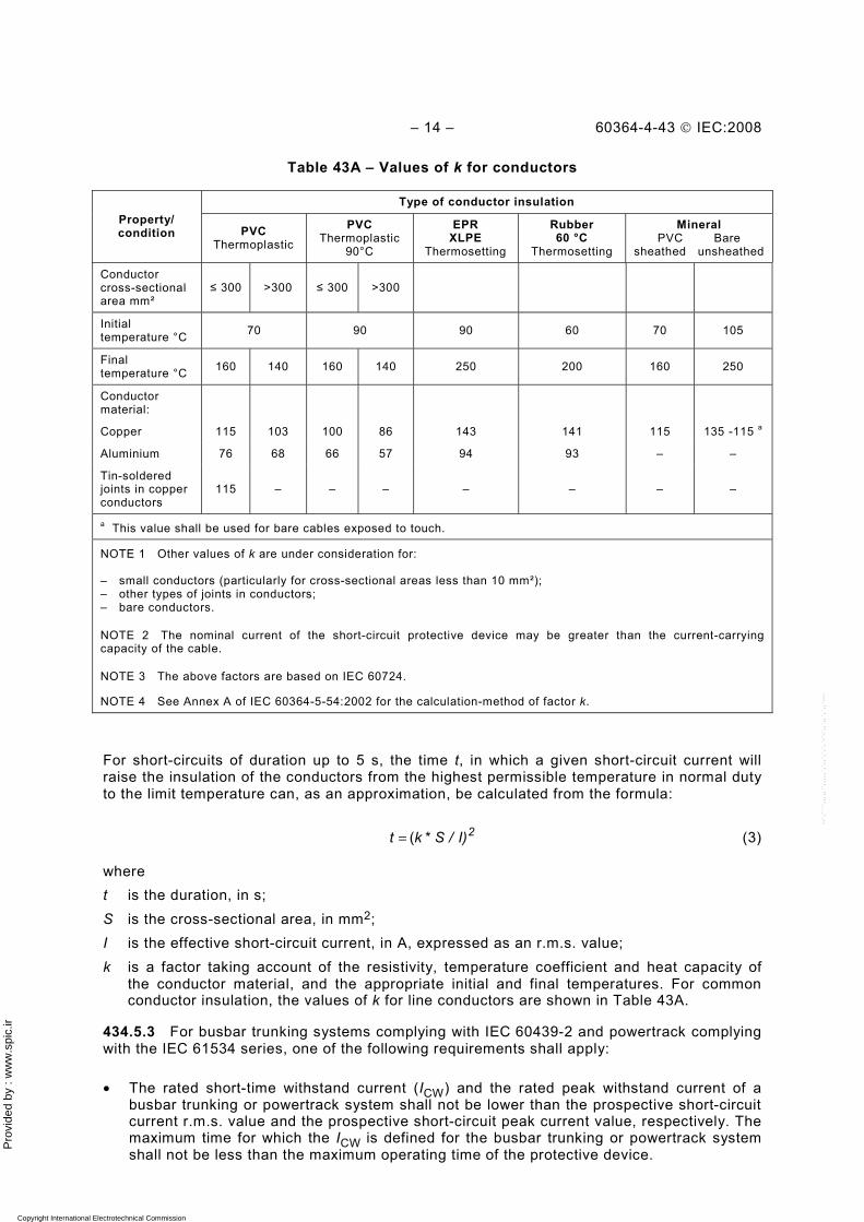
Table 43A – Values of k for conductors
Type of conductor insulation Property/ condition PVC
Thermoplastic PVC
Thermoplastic90°C
EPR XLPE
Thermosetting
Rubber 60 °C
Thermosetting
Mineral PVC Bare
sheathed unsheathed
Conductor cross-sectional area mm²
≤ 300 >300 ≤ 300 >300
Initial temperature °C 70 90 90 60 70 105
Final temperature °C 160 140 160 140 250 200 160 250
Conductor material:
Copper 115 103 100 86 143 141 115 135 -115 a
Aluminium 76 68 66 57 94 93 – –
Tin-soldered joints in copper conductors
115 – – – – – – –
a This value shall be used for bare cables exposed to touch.
NOTE 1 Other values of k are under consideration for: – small conductors (particularly for cross-sectional areas less than 10 mm²); – other types of joints in conductors; – bare conductors.
NOTE 2 The nominal current of the short-circuit protective device may be greater than the current-carrying capacity of the cable.
NOTE 3 The above factors are based on IEC 60724.
NOTE 4 See Annex A of IEC 60364-5-54:2002 for the calculation-method of factor k.
For short-circuits of duration up to 5 s, the time t, in which a given short-circuit current will raise the insulation of the conductors from the highest permissible temperature in normal duty to the limit temperature can, as an approximation, be calculated from the formula:
2I) /S *kt (= (3)
where t is the duration, in s; S is the cross-sectional area, in mm2; I is the effective short-circuit current, in A, expressed as an r.m.s. value; k is a factor taking account of the resistivity, temperature coefficient and heat capacity of
the conductor material, and the appropriate initial and final temperatures. For common conductor insulation, the values of k for line conductors are shown in Table 43A.
434.5.3 For busbar trunking systems complying with IEC 60439-2 and powertrack complying with the IEC 61534 series, one of the following requirements shall apply:
• The rated short-time withstand current (ICW) and the rated peak withstand current of a busbar trunking or powertrack system shall not be lower than the prospective short-circuit current r.m.s. value and the prospective short-circuit peak current value, respectively. The maximum time for which the ICW is defined for the busbar trunking or powertrack system shall not be less than the maximum operating time of the protective device.
Copyright International Electrotechnical Commission Provided by IHS under license with IEC Licensee=Hong Kong Polytechnic Univ/9976803100
Not for Resale, 12/31/2010 02:47:20 MSTNo reproduction or networking permitted without license from IHS
--`,````,,,,,``,,,,,`,`,,`,`,`,`-`-`,,`,,`,`,,`---
Pro
vide
d by
: w
ww
.spi
c.ir
60364-4-43 © IEC:2008 – 15 –
• The rated conditional short-circuit current of the busbar trunking or powertrack system associated with a specific protective device, shall not be lower than the prospective short-circuit current.
435 Coordination of overload and short-circuit protection
435.1 Protection afforded by one device
A protective device providing protection against overload and short-circuit currents shall fulfil the applicable requirements of Clauses of 433 and 434.
435.2 Protection afforded by separate devices
The requirements of Clauses 433 and 434 apply, respectively, to the overload protective device and the short-circuit protective device.
The characteristics of the devices shall be coordinated so that the energy let through by the short-circuit protective device does not exceed that which can be withstood without damage by the overload protective device.
NOTE This requirement does not exclude the type of coordination specified in IEC 60947-4-1.
436 Limitation of overcurrent by characteristics of supply
Conductors are considered to be protected against overload and short-circuit currents where they are supplied from a source incapable of supplying a current exceeding the current-carrying capacity of the conductors (e.g. certain bell transformers, certain welding transformers and certain types of thermoelectric generating sets).
Copyright International Electrotechnical Commission Provided by IHS under license with IEC Licensee=Hong Kong Polytechnic Univ/9976803100
Not for Resale, 12/31/2010 02:47:20 MSTNo reproduction or networking permitted without license from IHS
--`,````,,,,,``,,,,,`,`,,`,`,`,`-`-`,,`,,`,`,,`---
Pro
vide
d by
: w
ww
.spi
c.ir
– 16 – 60364-4-43 © IEC:2008
Annex A (informative)
Protection of conductors in parallel against overcurrent
A.1 Introduction
Overcurrent protection for conductors connected in parallel should provide adequate protection for all of the parallel conductors. For two conductors of the same cross-sectional area, conductor material length and method of installation arranged to carry substantially equal currents, the requirements for overcurrent protection are straightforward. For more complex conductor arrangements, detailed consideration should be given to unequal current sharing between conductors and multiple fault current paths. This annex gives guidance on the necessary considerations.
NOTE A more detailed method for calculating the current between parallel conductors is given in IEC 60287-1-3.
A.2 Overload protection of conductors in parallel
When an overload occurs in a circuit containing parallel conductors of multicore cables, the current in each conductor will increase by the same proportion. Provided that the current is shared equally between the parallel conductors, a single protective device can be used to protect all the conductors. The current-carrying capacity (Iz) of the parallel conductors is the sum of the current-carrying capacity of each conductor, with the appropriate grouping and other factors applied.
The current sharing between parallel cables is a function of the impedance of the cables. For large, single-core cables the reactive component of the impedance is greater than the resistive component and will have a significant effect on the current sharing. The reactive component is influenced by the relative physical position of each cable. If, for example, a circuit consists of two large cables per phase, having the same length, construction and cross-sectional area and arranged in parallel but with adverse relative positioning (i.e. cables of the same phase bunched together) the current sharing may be 70 %/30 % rather than 50 %/50 %.
Where the difference in impedance between parallel conductors causes unequal current sharing, for example greater than 10 % difference, the design current and requirements for overload protection for each conductor should be considered individually.
The design current for each conductor can be calculated from the total load and the impedance of each conductor.
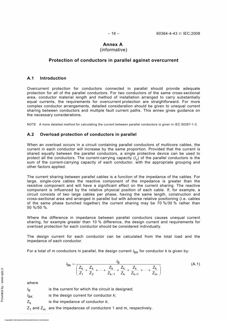
For a total of m conductors in parallel, the design current IBK for conductor k is given by:
⎟⎟⎠
⎞⎜⎜⎝
⎛+⋅⋅⋅++++⋅⋅⋅++
=
+− m
k
1k
k
k
k
1k
k
2
k
1
k
BBk
ZZ
ZZ
ZZ
ZZ
ZZ
ZZ
II (A.1)
where IB is the current for which the circuit is designed; IBK is the design current for conductor k; Zk is the impedance of conductor k; Z1 and Zm are the impedances of conductors 1 and m, respectively.
Copyright International Electrotechnical Commission Provided by IHS under license with IEC Licensee=Hong Kong Polytechnic Univ/9976803100
Not for Resale, 12/31/2010 02:47:20 MSTNo reproduction or networking permitted without license from IHS
--`,````,,,,,``,,,,,`,`,,`,`,`,`-`-`,,`,,`,`,,`---
Pro
vide
d by
: w
ww
.spi
c.ir
60364-4-43 © IEC:2008 – 17 –
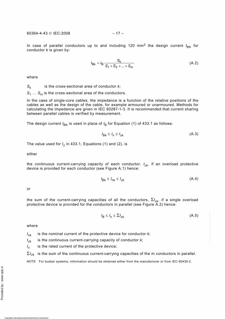
In case of parallel conductors up to and including 120 mm2 the design current IBK for conductor k is given by:
m21
kBBk ... SSS
SII
+++= (A.2)
where
Sk is the cross-sectional area of conductor k;
S1 … Sm is the cross-sectional area of the conductors.
In the case of single-core cables, the impedance is a function of the relative positions of the cables as well as the design of the cable, for example armoured or unarmoured. Methods for calculating the impedance are given in IEC 60287-1-3. It is recommended that current sharing between parallel cables is verified by measurement.
The design current IBK is used in place of IB for Equation (1) of 433.1 as follows:
IBk ≤ In ≤ Izk (A.3)
The value used for Iz in 433.1, Equations (1) and (2), is
either
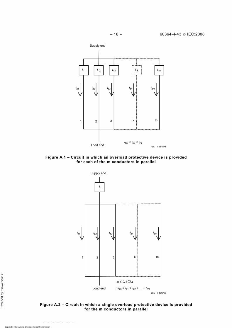
the continuous current-carrying capacity of each conductor, Izk, if an overload protective device is provided for each conductor (see Figure A.1) hence:
IBk ≤ Ink ≤ Izk (A.4)
or
the sum of the current-carrying capacities of all the conductors, ΣIzk, if a single overload protective device is provided for the conductors in parallel (see Figure A.2) hence:
IB ≤ In ≤ ΣIzk (A.5)
where
Ink is the nominal current of the protective device for conductor k; Izk is the continuous current-carrying capacity of conductor k; In is the rated current of the protective device;
ΣIzk is the sum of the continuous current-carrying capacities of the m conductors in parallel.
NOTE For busbar systems, information should be obtained either from the manufacturer or from IEC 60439-2.
Copyright International Electrotechnical Commission Provided by IHS under license with IEC Licensee=Hong Kong Polytechnic Univ/9976803100
Not for Resale, 12/31/2010 02:47:20 MSTNo reproduction or networking permitted without license from IHS
--`,````,,,,,``,,,,,`,`,,`,`,`,`-`-`,,`,,`,`,,`---
Pro
vide
d by
: w
ww
.spi
c.ir
– 18 – 60364-4-43 © IEC:2008
Load end
1 2 3
Inm Ink In3 In2 In1
IBk ≤ Ink ≤ Izk
Iz1 IzmIzkIz3Iz2
m
Supply end
k
IEC 1 584/98
Figure A.1 – Circuit in which an overload protective device is provided for each of the m conductors in parallel
1 2 3
IzmIzkIz3Iz2
ΣIzk = Iz1 + Iz2 + ... + Izm
IB ≤ In ≤ ΣIzk
Iz1
mk
Supply end
In
Load end IEC 1 585/98
Figure A.2 – Circuit in which a single overload protective device is provided for the m conductors in parallel
Copyright International Electrotechnical Commission Provided by IHS under license with IEC Licensee=Hong Kong Polytechnic Univ/9976803100
Not for Resale, 12/31/2010 02:47:20 MSTNo reproduction or networking permitted without license from IHS
--`,````,,,,,``,,,,,`,`,,`,`,`,`-`-`,,`,,`,`,,`---
Pro
vide
d by
: w
ww
.spi
c.ir
60364-4-43 © IEC:2008 – 19 –
A.3 Short-circuit protection of conductors in parallel
Where conductors are connected in parallel, the effect of a short-circuit within the parallel section should be considered with respect to the protective device arrangement.
Individual conductors in a parallel arrangement may not be effectively protected when using single protective devices, thus consideration should be given to providing other protective arrangements. These could include individual protective devices for each conductor, protective devices at the supply and load ends of the parallel conductors, and linked protective devices at the supply end. Determination of the particular protection arrangement will be dependent on the likelihood of fault conditions.
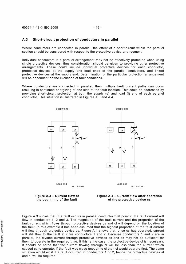
Where conductors are connected in parallel, then multiple fault current paths can occur resulting in continued energizing of one side of the fault location. This could be addressed by providing short-circuit protection at both the supply (s) and load (l) end of each parallel conductor. This situation is illustrated in Figures A.3 and A.4.
1 2 3
x
bs cs as
bl cl al
1 2 3
x
bs cs as
bl cl al
Load end Load end
Supply end Supply end
IEC 1 587/98 IEC 1 586/98
Figure A.3 – Current flow at the beginning of the fault
Figure A.4 – Current flow after operation of the protective device cs
Figure A.3 shows that, if a fault occurs in parallel conductor 3 at point x, the fault current will flow in conductors 1, 2 and 3. The magnitude of the fault current and the proportion of the fault current which flows through protective devices cs and cl will depend on the location of the fault. In this example it has been assumed that the highest proportion of the fault current will flow through protective device cs. Figure A.4 shows that, once cs has operated, current will still flow to the fault at x via conductors 1 and 2. Because conductors 1 and 2 are in parallel, the divided current through protective devices as and bs may not be sufficient for them to operate in the required time. If this is the case, the protective device cl is necessary. It should be noted that the current flowing through cl will be less than the current which caused cs to operate. If the fault was close enough to cl then cl would operate first. The same situation would exist if a fault occurred in conductors 1 or 2, hence the protective devices al and bl will be required.
Copyright International Electrotechnical Commission Provided by IHS under license with IEC Licensee=Hong Kong Polytechnic Univ/9976803100
Not for Resale, 12/31/2010 02:47:20 MSTNo reproduction or networking permitted without license from IHS
--`,````,,,,,``,,,,,`,`,,`,`,`,`-`-`,,`,,`,`,,`---
Pro
vide
d by
: w
ww
.spi
c.ir
– 20 – 60364-4-43 © IEC:2008
The method of providing protective devices at both ends has two disadvantages compared to the method of providing protective devices at the supply ends only. Firstly, if a fault of x is cleared by the operation of cs and cl, then the circuit will continue to operate with the load being carried by conductors 1 and 2. Hence, the fault and subsequent overloading of conductors 1 and 2 may not be detected, depending on the fault impedance. Secondly, the fault at x may burn open-circuit at the cl side, leaving one side of the fault live and undetected.
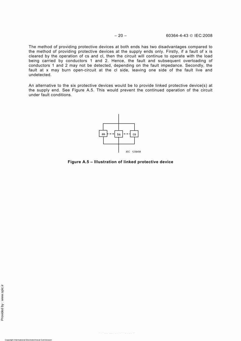
An alternative to the six protective devices would be to provide linked protective device(s) at the supply end. See Figure A.5. This would prevent the continued operation of the circuit under fault conditions.
bs cs as
IEC 1239/08
Figure A.5 – Illustration of linked protective device
Copyright International Electrotechnical Commission Provided by IHS under license with IEC Licensee=Hong Kong Polytechnic Univ/9976803100
Not for Resale, 12/31/2010 02:47:20 MSTNo reproduction or networking permitted without license from IHS
--`,````,,,,,``,,,,,`,`,,`,`,`,`-`-`,,`,,`,`,,`---
Pro
vide
d by
: w
ww
.spi
c.ir
60364-4-43 © IEC:2008 – 21 –
Annex B (informative)
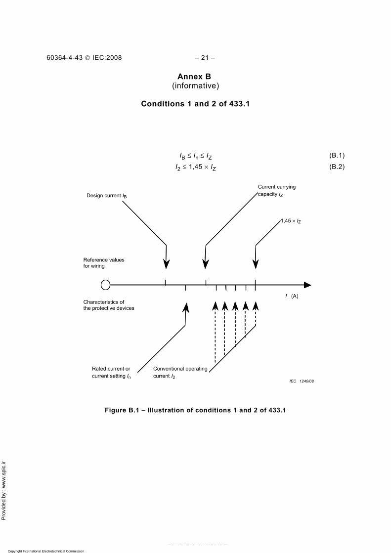
Conditions 1 and 2 of 433.1
IB ≤ In ≤ IZ (B.1)
I2 ≤ 1,45 × IZ (B.2)
Design current IB Current carrying capacity IZ
1,45 × IZ
Reference values for wiring
Characteristics of the protective devices
Rated current or current setting In
Conventional operating current I2
I (A)
IEC 1240/08
Figure B.1 – Illustration of conditions 1 and 2 of 433.1
Copyright International Electrotechnical Commission Provided by IHS under license with IEC Licensee=Hong Kong Polytechnic Univ/9976803100
Not for Resale, 12/31/2010 02:47:20 MSTNo reproduction or networking permitted without license from IHS
--`,````,,,,,``,,,,,`,`,,`,`,`,`-`-`,,`,,`,`,,`---
Pro
vide
d by
: w
ww
.spi
c.ir
– 22 – 60364-4-43 © IEC:2008
Annex C (informative)
Position or omission of devices for overload protection
C.1 General
Devices for overload protection and devices for short-circuit protection have to be installed for each circuit. These protective devices generally need to be placed at the origin of each circuit.
For some applications, one of the devices for overload protection or for short-circuit protection may not follow this general requirement, provided the other protection remains operative.
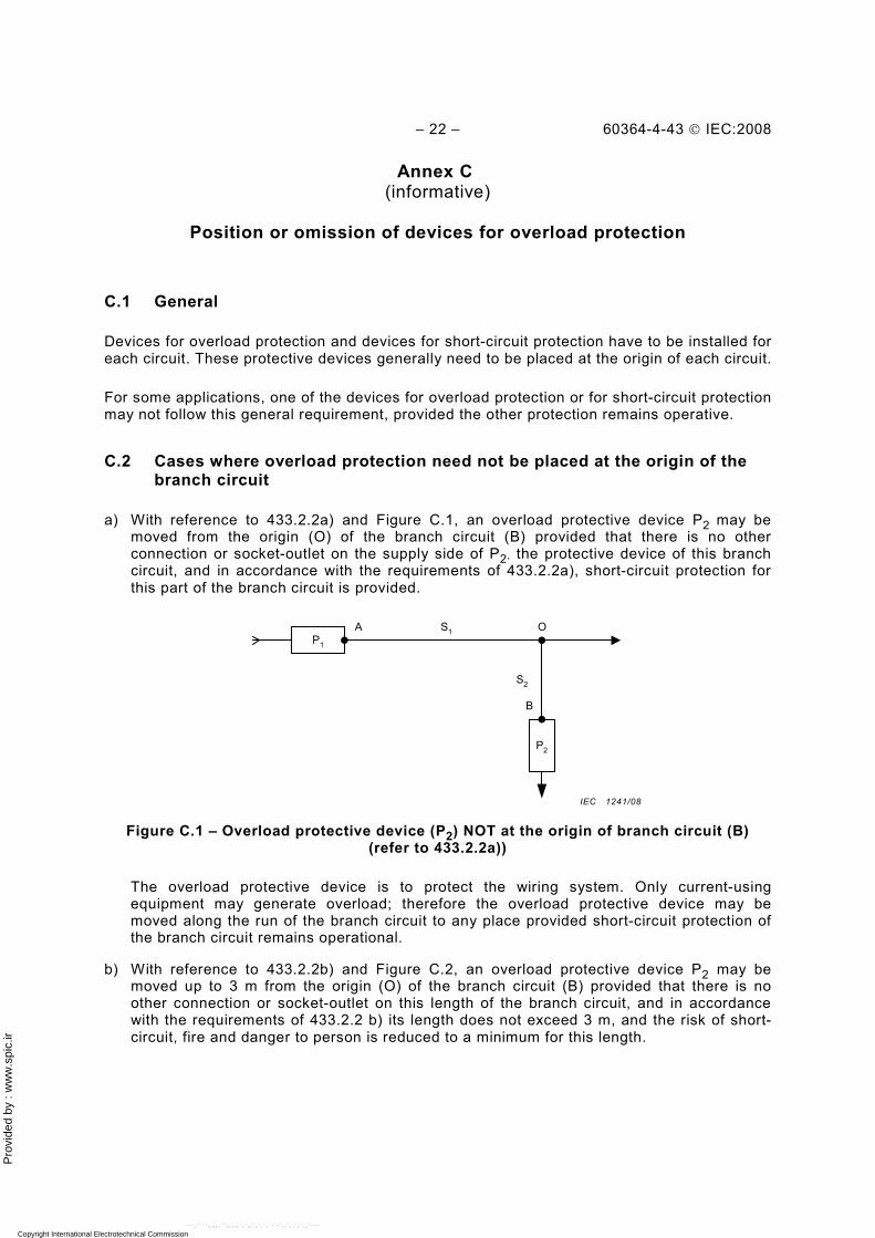
C.2 Cases where overload protection need not be placed at the origin of the branch circuit
a) With reference to 433.2.2a) and Figure C.1, an overload protective device P2 may be moved from the origin (O) of the branch circuit (B) provided that there is no other connection or socket-outlet on the supply side of P2, the protective device of this branch circuit, and in accordance with the requirements of 433.2.2a), short-circuit protection for this part of the branch circuit is provided.
A
B
OS1
S2
P1
P2
Figure C.1 – Overload protective device (P2) NOT at the origin of branch circuit (B)
(refer to 433.2.2a))
The overload protective device is to protect the wiring system. Only current-using equipment may generate overload; therefore the overload protective device may be moved along the run of the branch circuit to any place provided short-circuit protection of the branch circuit remains operational.
b) With reference to 433.2.2b) and Figure C.2, an overload protective device P2 may be moved up to 3 m from the origin (O) of the branch circuit (B) provided that there is no other connection or socket-outlet on this length of the branch circuit, and in accordance with the requirements of 433.2.2 b) its length does not exceed 3 m, and the risk of short-circuit, fire and danger to person is reduced to a minimum for this length.
IEC 1241/08
Copyright International Electrotechnical Commission Provided by IHS under license with IEC Licensee=Hong Kong Polytechnic Univ/9976803100
Not for Resale, 12/31/2010 02:47:20 MSTNo reproduction or networking permitted without license from IHS
--`,````,,,,,``,,,,,`,`,,`,`,`,`-`-`,,`,,`,`,,`---
Pro
vide
d by
: w
ww
.spi
c.ir
60364-4-43 © IEC:2008 – 23 –
A
B
OS1
S2
P1
P2
<3m
Figure C.2 – Overload protective device (P2) installed within 3 m of the origin of the
branch circuit (B) (refer to 433.2.2b))
It is accepted that for a length of 3 m, the branch circuit is not protected against short-circuit, but precautions have to be taken to ensure safety. See 433.2.2b). In addition it may be possible that the short-circuit protection of the supply circuit also provides short-circuit protection to the branch circuit up to the point where P2 is installed (see Annex D).
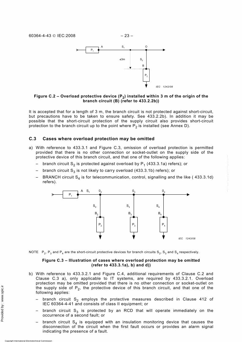
C.3 Cases where overload protection may be omitted
a) With reference to 433.3.1 and Figure C.3, omission of overload protection is permitted provided that there is no other connection or socket-outlet on the supply side of the protective device of this branch circuit, and that one of the following applies: – branch circuit S2 is protected against overload by P1 (433.3.1a) refers); or – branch circuit S3 is not likely to carry overload (433.3.1b) refers); or – BRANCH circuit S4 is for telecommunication, control, signalling and the like ( 433.3.1d)
refers).
A S1
S3
P1
P3
02
S2
P2
S4
P4
03 04
B2 B3 B4
NOTE P2, P3 and P4 are the short-circuit protective devices for branch circuits S2, S3 and S4 respectively.
Figure C.3 – Illustration of cases where overload protection may be omitted (refer to 433.3.1a), b) and d))
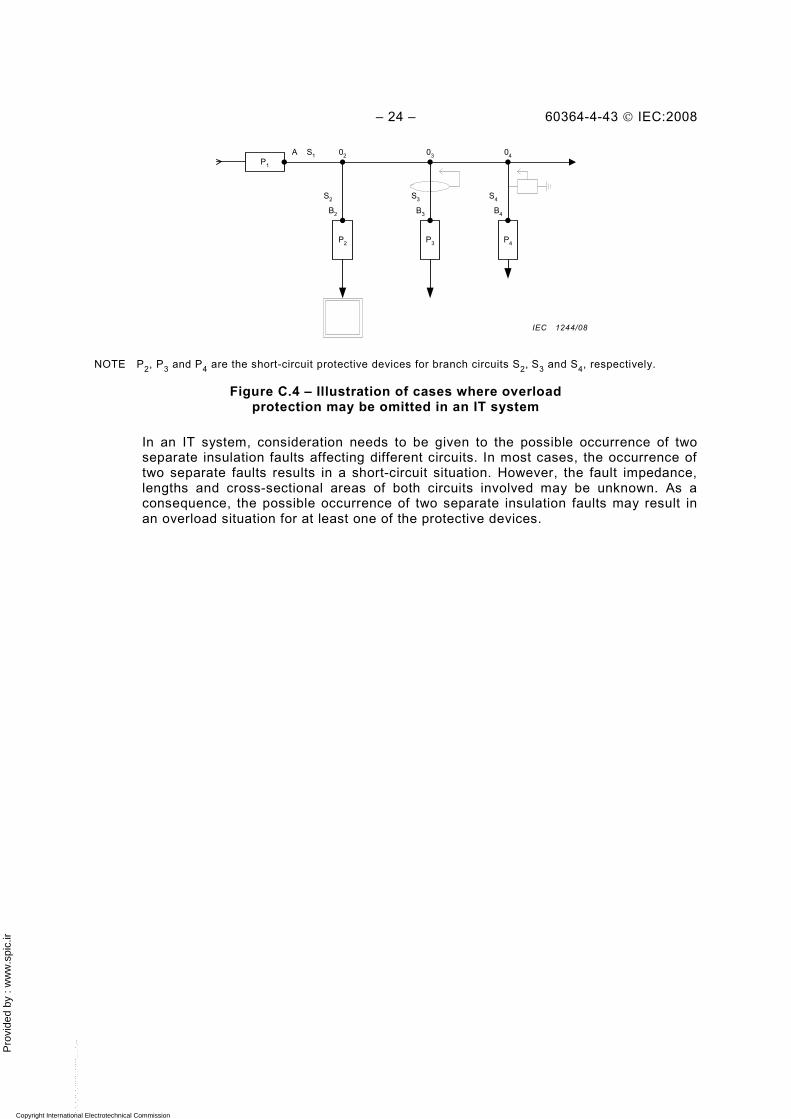
b) With reference to 433.3.2.1 and Figure C.4, additional requirements of Clause C.2 and Clause C.3 a), only applicable to IT systems, are required by 433.3.2.1. Overload protection may be omitted provided that there is no other connection or socket-outlet on the supply side of P2, the protective device of this branch circuit, and that one of the following applies: – branch circuit S2 employs the protective measures described in Clause 412 of
IEC 60364-4-41 and consists of class II equipment; or – branch circuit S3 is protected by an RCD that will operate immediately on the
occurrence of a second fault; or – branch circuit S4 is equipped with an insulation monitoring device that causes the
disconnection of the circuit when the first fault occurs or provides an alarm signal indicating the presence of a fault.
IEC 1242/08
IEC 1243/08
Copyright International Electrotechnical Commission Provided by IHS under license with IEC Licensee=Hong Kong Polytechnic Univ/9976803100
Not for Resale, 12/31/2010 02:47:20 MSTNo reproduction or networking permitted without license from IHS
--`,````,,,,,``,,,,,`,`,,`,`,`,`-`-`,,`,,`,`,,`---
Pro
vide
d by
: w
ww
.spi
c.ir
– 24 – 60364-4-43 © IEC:2008
A S1
S3
P1
P3
02
S2
P2
S4
P4
03 04
B2 B3 B4
NOTE P2, P3 and P4 are the short-circuit protective devices for branch circuits S2, S3 and S4, respectively.
Figure C.4 – Illustration of cases where overload protection may be omitted in an IT system
In an IT system, consideration needs to be given to the possible occurrence of two separate insulation faults affecting different circuits. In most cases, the occurrence of two separate faults results in a short-circuit situation. However, the fault impedance, lengths and cross-sectional areas of both circuits involved may be unknown. As a consequence, the possible occurrence of two separate insulation faults may result in an overload situation for at least one of the protective devices.
IEC 1244/08
Copyright International Electrotechnical Commission Provided by IHS under license with IEC Licensee=Hong Kong Polytechnic Univ/9976803100
Not for Resale, 12/31/2010 02:47:20 MSTNo reproduction or networking permitted without license from IHS
--`,````,,,,,``,,,,,`,`,,`,`,`,`-`-`,,`,,`,`,,`---
Pro
vide
d by
: w
ww
.spi
c.ir
60364-4-43 © IEC:2008 – 25 –
Annex D (informative)
Position or omission of devices for short-circuit protection
D.1 General
Devices for overload protection and devices for short-circuit protection have to be installed for each circuit. These protective devices generally need to be placed at the origin of each circuit.
For some applications, one of the devices for overload protection or for short-circuit protection may not follow this general requirement, provided the other protection remains operative.
D.2 Cases where short-circuit protection does not need to be placed at the origin of branch circuit
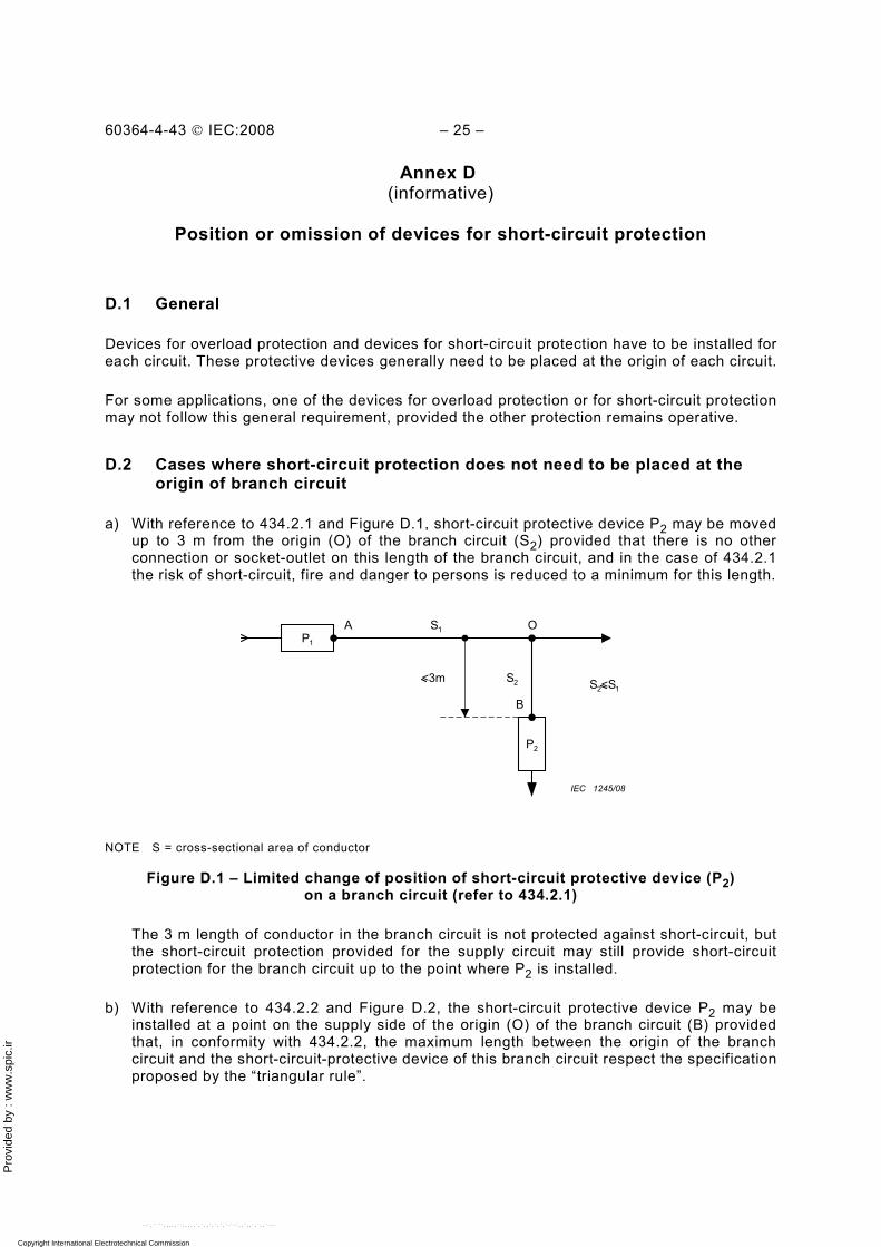
a) With reference to 434.2.1 and Figure D.1, short-circuit protective device P2 may be moved up to 3 m from the origin (O) of the branch circuit (S2) provided that there is no other connection or socket-outlet on this length of the branch circuit, and in the case of 434.2.1 the risk of short-circuit, fire and danger to persons is reduced to a minimum for this length.
A
B
OS1
S2
P 1
P2
S2<S1<3m
IEC 1245/08
NOTE S = cross-sectional area of conductor
Figure D.1 – Limited change of position of short-circuit protective device (P2) on a branch circuit (refer to 434.2.1)
The 3 m length of conductor in the branch circuit is not protected against short-circuit, but the short-circuit protection provided for the supply circuit may still provide short-circuit protection for the branch circuit up to the point where P2 is installed.
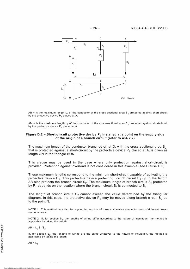
b) With reference to 434.2.2 and Figure D.2, the short-circuit protective device P2 may be installed at a point on the supply side of the origin (O) of the branch circuit (B) provided that, in conformity with 434.2.2, the maximum length between the origin of the branch circuit and the short-circuit-protective device of this branch circuit respect the specification proposed by the “triangular rule”.
Copyright International Electrotechnical Commission Provided by IHS under license with IEC Licensee=Hong Kong Polytechnic Univ/9976803100
Not for Resale, 12/31/2010 02:47:20 MSTNo reproduction or networking permitted without license from IHS
--`,````,,,,,``,,,,,`,`,,`,`,`,`-`-`,,`,,`,`,,`---
Pro
vide
d by
: w
ww
.spi
c.ir
– 26 – 60364-4-43 © IEC:2008
AB = is the maximum length L1 of the conductor of the cross-sectional area S1 protected against short-circuit by the protective device P1 placed at A.
AM = is the maximum length L2 of the conductor of the cross-sectional area S2 protected against short-circuit by the protective device P1 placed at A.
Figure D.2 – Short-circuit protective device P2 installed at a point on the supply side of the origin of a branch circuit (refer to 434.2.2)
The maximum length of the conductor branched off at O, with the cross-sectional area S2, that is protected against a short-circuit by the protective device P1 placed at A, is given as length ON in the triangle BON.
This clause may be used in the case where only protection against short-circuit is provided. Protection against overload is not considered in this example (see Clause C.3).
These maximum lengths correspond to the minimum short-circuit capable of activating the protective device P1. This protective device protecting branch circuit S1 up to the length AB also protects the branch circuit S2. The maximum length of branch circuit S2 protected by P1 depends on the location where the branch circuit S2 is connected to S1.
The length of branch circuit S2 cannot exceed the value determined by the triangular diagram. In this case, the protective device P2 may be moved along branch circuit S2 up to the point N.
NOTE 1 This method may also be applied in the case of three successive conductor runs of different cross-sectional area.
NOTE 2 If, for section S2, the lengths of wiring differ according to the nature of insulation, the method is applicable by taking the length:
AB = L2 S1/S2
If, for section S2, the lengths of wiring are the same whatever to the nature of insulation, the method is applicable by taking the length:
AB = L1
A
S1 S2
P 1
P2
B0
S2
S1
S2
P2
P 2
M
S 2 P2
O B
N
M
A
N
L1
L2
IEC 1246/08
L1
Copyright International Electrotechnical Commission Provided by IHS under license with IEC Licensee=Hong Kong Polytechnic Univ/9976803100
Not for Resale, 12/31/2010 02:47:20 MSTNo reproduction or networking permitted without license from IHS
--`,````,,,,,``,,,,,`,`,,`,`,`,`-`-`,,`,,`,`,,`---
Pro
vide
d by
: w
ww
.spi
c.ir
60364-4-43 © IEC:2008 – 27 –
D.3 Case where short-circuit protection may be omitted
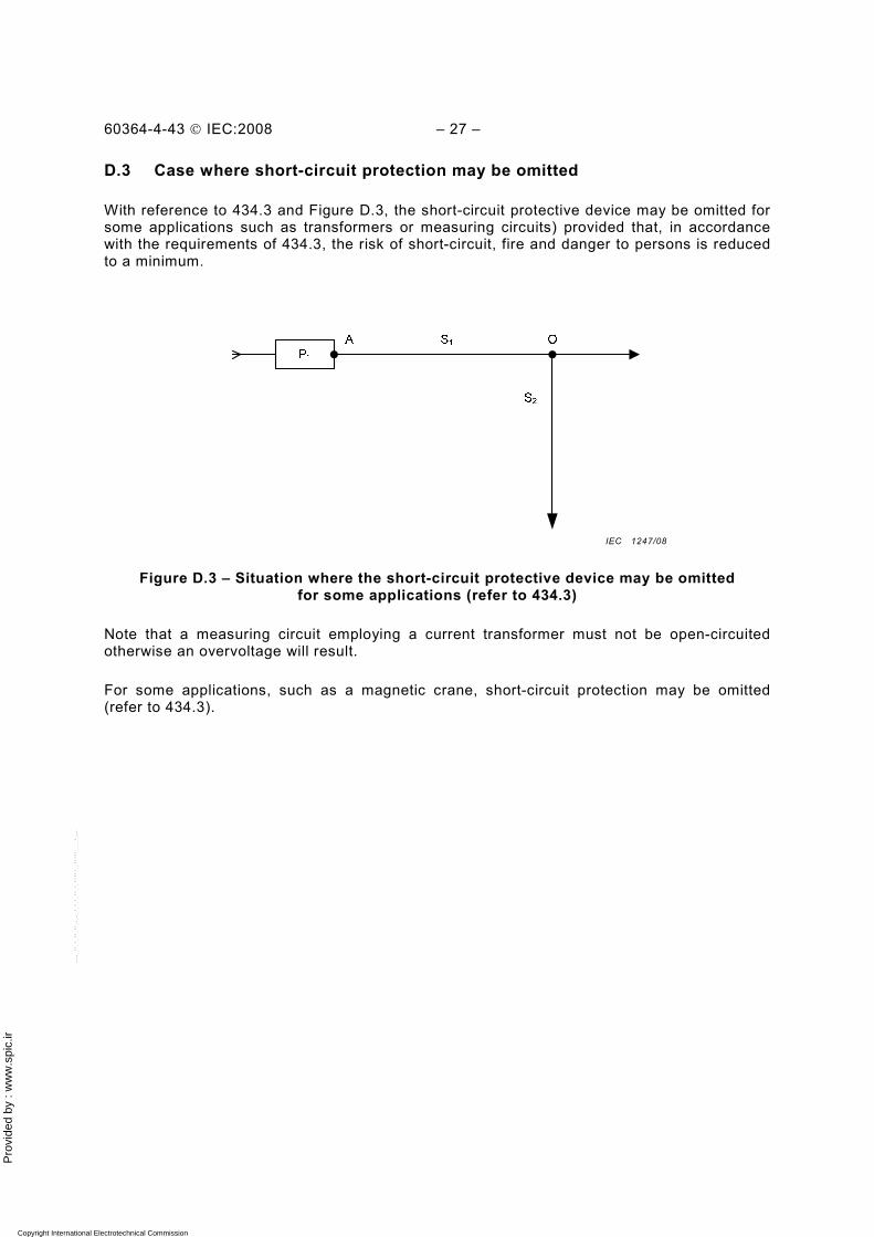
With reference to 434.3 and Figure D.3, the short-circuit protective device may be omitted for some applications such as transformers or measuring circuits) provided that, in accordance with the requirements of 434.3, the risk of short-circuit, fire and danger to persons is reduced to a minimum.
Figure D.3 – Situation where the short-circuit protective device may be omitted for some applications (refer to 434.3)
Note that a measuring circuit employing a current transformer must not be open-circuited otherwise an overvoltage will result.
For some applications, such as a magnetic crane, short-circuit protection may be omitted (refer to 434.3).
IEC 1247/08
Copyright International Electrotechnical Commission Provided by IHS under license with IEC Licensee=Hong Kong Polytechnic Univ/9976803100
Not for Resale, 12/31/2010 02:47:20 MSTNo reproduction or networking permitted without license from IHS
--`,````,,,,,``,,,,,`,`,,`,`,`,`-`-`,,`,,`,`,,`---
Pro
vide
d by
: w
ww
.spi
c.ir
– 28 – 60364-4-43 © IEC:2008
Annex E (informative)
List of notes concerning certain countries
Country Clause N°
Nature (permanent or
less permanent according to
IEC Directives)
Rationale (detailed justification
for the requested country note)
Wording
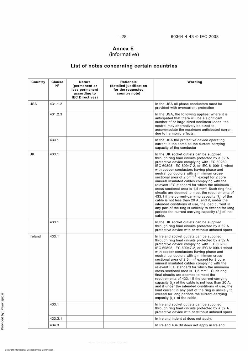
431.1.2 In the USA all phase conductors must be provided with overcurrent protection
431.2.3 In the USA, the following applies: where it is anticipated that there will be a significant number of or large sized nonlinear loads, the neutral may alternatively be sized to accommodate the maximum anticipated current due to harmonic effects.
USA
433.1 In the USA the protective device operating current is the same as the current-carrying capacity of the conductor
433.1 In the UK socket outlets can be supplied through ring final circuits protected by a 32 A protective device complying with IEC 60269, IEC 60898, IEC 60947-2, or IEC 61009-1, wired with copper conductors having phase and neutral conductors with a minimum cross- sectional area of 2,5mm2 except for 2 core mineral insulated cables complying with the relevant IEC standard for which the minimum cross-sectional area is 1,5 mm². Such ring final circuits are deemed to meet the requirements of 433.1 if the current-carrying capacity (Iz) of the cable is not less than 20 A, and if, under the intended conditions of use, the load current in any part of the ring is unlikely to exceed for long periods the current carrying capacity (Iz) of the cable.
UK
433.1 In the UK socket outlets can be supplied through ring final circuits protected by a 32 A protective device with or without unfused spurs
433.1 In Ireland socket outlets can be supplied through ring final circuits protected by a 32 A protective device complying with IEC 60269, IEC 60898, IEC 60947-2, or IEC 61009-1 wired with copper conductors having phase and neutral conductors with a minimum cross- sectional area of 2,5mm2 except for 2 core mineral insulated cables complying with the relevant IEC standard for which the minimum cross-sectional area is 1,5 mm² . Such ring final circuits are deemed to meet the requirements of 433.1 if the current-carrying capacity (Iz) of the cable is not less than 20 A, and if under the intended conditions of use, the load current in any part of the ring is unlikely to exceed for long periods the current-carrying capacity (Iz) of the cable
433.1 In Ireland socket outlets can be supplied through ring final circuits protected by a 32 A protective device with or without unfused spurs
433.3.1 In Ireland indent c) does not apply.
Ireland
434.3 In Ireland 434.3d does not apply in Ireland
Copyright International Electrotechnical Commission Provided by IHS under license with IEC Licensee=Hong Kong Polytechnic Univ/9976803100
Not for Resale, 12/31/2010 02:47:20 MSTNo reproduction or networking permitted without license from IHS
--`,````,,,,,``,,,,,`,`,,`,`,`,`-`-`,,`,,`,`,,`---
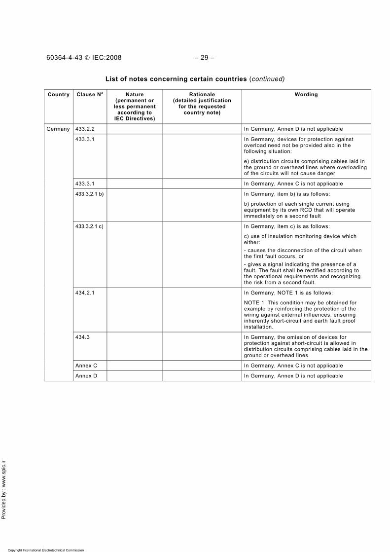
Pro
vide
d by
: w
ww
.spi
c.ir
60364-4-43 © IEC:2008 – 29 –
List of notes concerning certain countries (continued)
Country Clause N° Nature (permanent or
less permanent according to
IEC Directives)
Rationale (detailed justification
for the requested country note)
Wording
433.2.2 In Germany, Annex D is not applicable
433.3.1 In Germany, devices for protection against overload need not be provided also in the following situation:
e) distribution circuits comprising cables laid in the ground or overhead lines where overloading of the circuits will not cause danger
433.3.1 In Germany, Annex C is not applicable
433.3.2.1 b) In Germany, item b) is as follows:
b) protection of each single current using equipment by its own RCD that will operate immediately on a second fault
433.3.2.1 c) In Germany, item c) is as follows:
c) use of insulation monitoring device which either: - causes the disconnection of the circuit when the first fault occurs, or - gives a signal indicating the presence of a fault. The fault shall be rectified according to the operational requirements and recognizing the risk from a second fault.
434.2.1 In Germany, NOTE 1 is as follows:
NOTE 1 This condition may be obtained for example by reinforcing the protection of the wiring against external influences. ensuring inherently short-circuit and earth fault proof installation.
434.3 In Germany, the omission of devices for protection against short-circuit is allowed in distribution circuits comprising cables laid in the ground or overhead lines
Annex C In Germany, Annex C is not applicable
Germany
Annex D In Germany, Annex D is not applicable
Copyright International Electrotechnical Commission Provided by IHS under license with IEC Licensee=Hong Kong Polytechnic Univ/9976803100
Not for Resale, 12/31/2010 02:47:20 MSTNo reproduction or networking permitted without license from IHS
--`,````,,,,,``,,,,,`,`,,`,`,`,`-`-`,,`,,`,`,,`---

Pro
vide
d by
: w
ww
.spi
c.ir
– 30 – 60364-4-43 © IEC:2008
Bibliography
IEC 60269-1: Low-voltage fuses – Part 1: General requirements
IEC 60287-1-3, Electric cables – Calculation of the current rating – Part 1-3: Current rating equations (100 % load factor) and calculation of losses – Current sharing between parallel single-core cables and calculation of circulating current losses
IEC 60364-5-54:2002, Electrical installations of buildings – Part 5-54: Selection and erection of electrical equipment – Earthing arrangements, protective conductors and protective bonding conductors
IEC 60439-2, Low-voltage switchgear and controlgear assemblies – Part 2: Particular requirements for busbar trunking systems (busways)
IEC 60947-1: Low-voltage switchgear and controlgear – Part 1: General rules
IEC 60947-4-1, Low-voltage switchgear and controlgear – Part 4-1: Contactors and motor-starters – Electromechanical contactors and motor-starters
IEC 61557-9, Electrical safety in low voltage distribution systems up to 1 000 V a.c. and 1 500 V d.c. – Equipment for testing, measuring or monitoring of protective measures – Part 9: Equipment for insulation fault location in IT systems
___________
Copyright International Electrotechnical Commission Provided by IHS under license with IEC Licensee=Hong Kong Polytechnic Univ/9976803100
Not for Resale, 12/31/2010 02:47:20 MSTNo reproduction or networking permitted without license from IHS
--`,````,,,,,``,,,,,`,`,,`,`,`,`-`-`,,`,,`,`,,`---

Pro
vide
d by
: w
ww
.spi
c.ir
Copyright International Electrotechnical Commission Provided by IHS under license with IEC Licensee=Hong Kong Polytechnic Univ/9976803100
Not for Resale, 12/31/2010 02:47:20 MSTNo reproduction or networking permitted without license from IHS
--`,````,,,,,``,,,,,`,`,,`,`,`,`-`-`,,`,,`,`,,`---
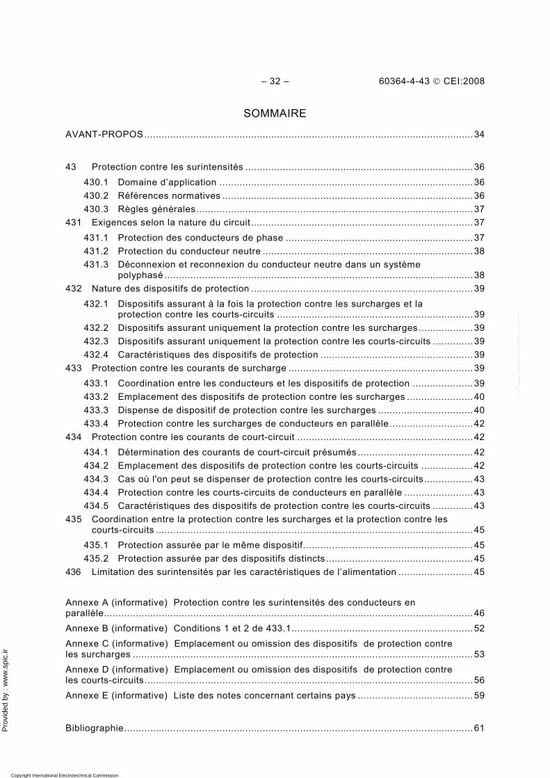
Pro
vide
d by
: w
ww
.spi
c.ir
– 32 – 60364-4-43 © CEI:2008
SOMMAIRE
AVANT-PROPOS..................................................................................................................34
43 Protection contre les surintensités ............................................................................... 36
430.1 Domaine d’application ........................................................................................ 36 430.2 Références normatives .......................................................................................36 430.3 Règles générales................................................................................................37
431 Exigences selon la nature du circuit .............................................................................37 431.1 Protection des conducteurs de phase ................................................................. 37 431.2 Protection du conducteur neutre ......................................................................... 38 431.3 Déconnexion et reconnexion du conducteur neutre dans un système
polyphasé ...........................................................................................................38 432 Nature des dispositifs de protection ............................................................................. 39
432.1 Dispositifs assurant à la fois la protection contre les surcharges et la protection contre les courts-circuits .................................................................... 39
432.2 Dispositifs assurant uniquement la protection contre les surcharges................... 39 432.3 Dispositifs assurant uniquement la protection contre les courts-circuits .............. 39 432.4 Caractéristiques des dispositifs de protection ..................................................... 39
433 Protection contre les courants de surcharge ................................................................ 39 433.1 Coordination entre les conducteurs et les dispositifs de protection ..................... 39 433.2 Emplacement des dispositifs de protection contre les surcharges ....................... 40 433.3 Dispense de dispositif de protection contre les surcharges ................................. 40 433.4 Protection contre les surcharges de conducteurs en parallèle............................. 42
434 Protection contre les courants de court-circuit ............................................................. 42 434.1 Détermination des courants de court-circuit présumés ........................................ 42 434.2 Emplacement des dispositifs de protection contre les courts-circuits .................. 42 434.3 Cas où l'on peut se dispenser de protection contre les courts-circuits................. 43 434.4 Protection contre les courts-circuits de conducteurs en parallèle ........................ 43 434.5 Caractéristiques des dispositifs de protection contre les courts-circuits .............. 43
435 Coordination entre la protection contre les surcharges et la protection contre les courts-circuits ..............................................................................................................45
435.1 Protection assurée par le même dispositif........................................................... 45 435.2 Protection assurée par des dispositifs distincts ...................................................45
436 Limitation des surintensités par les caractéristiques de l’alimentation .......................... 45 Annexe A (informative) Protection contre les surintensités des conducteurs en parallèle................................................................................................................................ 46 Annexe B (informative) Conditions 1 et 2 de 433.1............................................................... 52 Annexe C (informative) Emplacement ou omission des dispositifs de protection contre les surcharges ...................................................................................................................... 53 Annexe D (informative) Emplacement ou omission des dispositifs de protection contre les courts-circuits.................................................................................................................. 56 Annexe E (informative) Liste des notes concernant certains pays ........................................ 59
Bibliographie......................................................................................................................... 61
Copyright International Electrotechnical Commission Provided by IHS under license with IEC Licensee=Hong Kong Polytechnic Univ/9976803100
Not for Resale, 12/31/2010 02:47:20 MSTNo reproduction or networking permitted without license from IHS
--`,````,,,,,``,,,,,`,`,,`,`,`,`-`-`,,`,,`,`,,`---
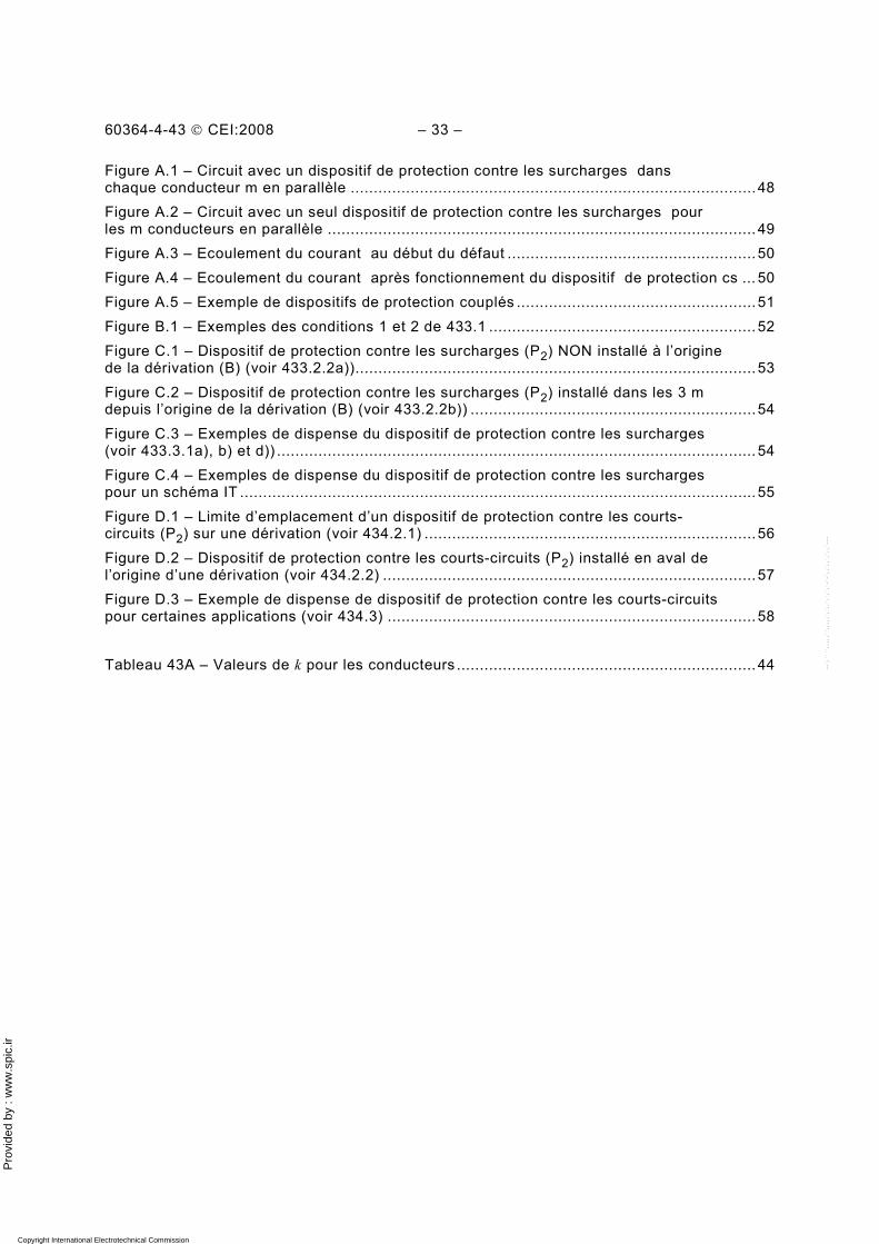
Pro
vide
d by
: w
ww
.spi
c.ir
60364-4-43 © CEI:2008 – 33 –
Figure A.1 – Circuit avec un dispositif de protection contre les surcharges dans chaque conducteur m en parallèle ........................................................................................ 48 Figure A.2 – Circuit avec un seul dispositif de protection contre les surcharges pour les m conducteurs en parallèle ............................................................................................. 49 Figure A.3 – Ecoulement du courant au début du défaut ...................................................... 50 Figure A.4 – Ecoulement du courant après fonctionnement du dispositif de protection cs ... 50 Figure A.5 – Exemple de dispositifs de protection couplés .................................................... 51 Figure B.1 – Exemples des conditions 1 et 2 de 433.1 .......................................................... 52 Figure C.1 – Dispositif de protection contre les surcharges (P2) NON installé à l’origine de la dérivation (B) (voir 433.2.2a))....................................................................................... 53 Figure C.2 – Dispositif de protection contre les surcharges (P2) installé dans les 3 m depuis l’origine de la dérivation (B) (voir 433.2.2b)) ..............................................................54 Figure C.3 – Exemples de dispense du dispositif de protection contre les surcharges (voir 433.3.1a), b) et d)) ........................................................................................................ 54 Figure C.4 – Exemples de dispense du dispositif de protection contre les surcharges pour un schéma IT ................................................................................................................ 55 Figure D.1 – Limite d’emplacement d’un dispositif de protection contre les courts-circuits (P2) sur une dérivation (voir 434.2.1) ........................................................................ 56 Figure D.2 – Dispositif de protection contre les courts-circuits (P2) installé en aval de l’origine d’une dérivation (voir 434.2.2) ................................................................................. 57 Figure D.3 – Exemple de dispense de dispositif de protection contre les courts-circuits pour certaines applications (voir 434.3) ................................................................................ 58 Tableau 43A – Valeurs de k pour les conducteurs ................................................................. 44
Copyright International Electrotechnical Commission Provided by IHS under license with IEC Licensee=Hong Kong Polytechnic Univ/9976803100
Not for Resale, 12/31/2010 02:47:20 MSTNo reproduction or networking permitted without license from IHS
--`,````,,,,,``,,,,,`,`,,`,`,`,`-`-`,,`,,`,`,,`---
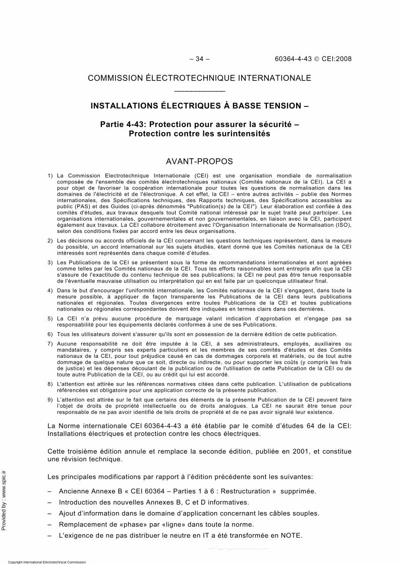
Pro
vide
d by
: w
ww
.spi
c.ir
– 34 – 60364-4-43 © CEI:2008
COMMISSION ÉLECTROTECHNIQUE INTERNATIONALE ____________
INSTALLATIONS ÉLECTRIQUES À BASSE TENSION –
Partie 4-43: Protection pour assurer la sécurité –
Protection contre les surintensités
AVANT-PROPOS 1) La Commission Electrotechnique Internationale (CEI) est une organisation mondiale de normalisation
composée de l'ensemble des comités électrotechniques nationaux (Comités nationaux de la CEI). La CEI a pour objet de favoriser la coopération internationale pour toutes les questions de normalisation dans les domaines de l'électricité et de l'électronique. A cet effet, la CEI – entre autres activités – publie des Normes internationales, des Spécifications techniques, des Rapports techniques, des Spécifications accessibles au public (PAS) et des Guides (ci-après dénommés "Publication(s) de la CEI"). Leur élaboration est confiée à des comités d'études, aux travaux desquels tout Comité national intéressé par le sujet traité peut participer. Les organisations internationales, gouvernementales et non gouvernementales, en liaison avec la CEI, participent également aux travaux. La CEI collabore étroitement avec l'Organisation Internationale de Normalisation (ISO), selon des conditions fixées par accord entre les deux organisations.
2) Les décisions ou accords officiels de la CEI concernant les questions techniques représentent, dans la mesure du possible, un accord international sur les sujets étudiés, étant donné que les Comités nationaux de la CEI intéressés sont représentés dans chaque comité d’études.
3) Les Publications de la CEI se présentent sous la forme de recommandations internationales et sont agréées comme telles par les Comités nationaux de la CEI. Tous les efforts raisonnables sont entrepris afin que la CEI s'assure de l'exactitude du contenu technique de ses publications; la CEI ne peut pas être tenue responsable de l'éventuelle mauvaise utilisation ou interprétation qui en est faite par un quelconque utilisateur final.
4) Dans le but d'encourager l'uniformité internationale, les Comités nationaux de la CEI s'engagent, dans toute la mesure possible, à appliquer de façon transparente les Publications de la CEI dans leurs publications nationales et régionales. Toutes divergences entre toutes Publications de la CEI et toutes publications nationales ou régionales correspondantes doivent être indiquées en termes clairs dans ces dernières.
5) La CEI n’a prévu aucune procédure de marquage valant indication d’approbation et n'engage pas sa responsabilité pour les équipements déclarés conformes à une de ses Publications.
6) Tous les utilisateurs doivent s'assurer qu'ils sont en possession de la dernière édition de cette publication.
7) Aucune responsabilité ne doit être imputée à la CEI, à ses administrateurs, employés, auxiliaires ou mandataires, y compris ses experts particuliers et les membres de ses comités d'études et des Comités nationaux de la CEI, pour tout préjudice causé en cas de dommages corporels et matériels, ou de tout autre dommage de quelque nature que ce soit, directe ou indirecte, ou pour supporter les coûts (y compris les frais de justice) et les dépenses découlant de la publication ou de l'utilisation de cette Publication de la CEI ou de toute autre Publication de la CEI, ou au crédit qui lui est accordé.
8) L'attention est attirée sur les références normatives citées dans cette publication. L'utilisation de publications référencées est obligatoire pour une application correcte de la présente publication.
9) L’attention est attirée sur le fait que certains des éléments de la présente Publication de la CEI peuvent faire l’objet de droits de propriété intellectuelle ou de droits analogues. La CEI ne saurait être tenue pour responsable de ne pas avoir identifié de tels droits de propriété et de ne pas avoir signalé leur existence.
La Norme internationale CEI 60364-4-43 a été établie par le comité d’études 64 de la CEI: Installations électriques et protection contre les chocs électriques.
Cette troisième édition annule et remplace la seconde édition, publiée en 2001, et constitue une révision technique.
Les principales modifications par rapport à l’édition précédente sont les suivantes:
– Ancienne Annexe B « CEI 60364 – Parties 1 à 6 : Restructuration » supprimée. – Introduction des nouvelles Annexes B, C et D informatives. – Ajout d’information dans le domaine d’application concernant les câbles souples. – Remplacement de «phase» par «ligne» dans toute la norme. – L'exigence de ne pas distribuer le neutre en IT a été transformée en NOTE.
Copyright International Electrotechnical Commission Provided by IHS under license with IEC Licensee=Hong Kong Polytechnic Univ/9976803100
Not for Resale, 12/31/2010 02:47:20 MSTNo reproduction or networking permitted without license from IHS
--`,````,,,,,``,,,,,`,`,,`,`,`,`-`-`,,`,,`,`,,`---
Pro
vide
d by
: w
ww
.spi
c.ir
60364-4-43 © CEI:2008 – 35 –
– Ajout d’exigence pour la détection de surcharge dans le conducteur neutre en cas de courants harmoniques.
– Ajout d’exigence pour que les dispositifs de protection contre les court-circuits soient capables d’opérer aussi bien à l’ouverture qu’à la fermeture sur un courant de court-circuit.
– Ajout d’information clarifiant la protection contre les courants de surcharge. – Développement des exigences où des dispositifs de protection contre les surcharges ne
sont pas nécessaire. – Plus d’exemples illustrent les cas où l'omission de dispositif de protection contre les
surcharges est permise. – Développement des exigences où des dispositifs de protection contre les courts-circuits
ne sont pas nécessaires. – Ajout d’exigences pour les courants de court-circuit assignés des systèmes de
canalisations préfabriquées.
Le texte de cette norme est issu des documents suivants:
FDIS Rapport de vote
64/1641/FDIS 64/1656/RVD
Le rapport de vote indiqué dans le tableau ci-dessus donne toute information sur le vote ayant abouti à l'approbation de cette norme.
Cette publication a été rédigée selon les Directives ISO/CEI, Partie 2.
L'attention du lecteur est attirée sur le fait que l'Annexe E liste tous les articles traitant des différences à caractère moins permanent inhérentes à certains pays sur le sujet de cette norme.
Elle a le statut de publication groupée de sécurité en accord avec le Guide CEI 104.
Une liste de toutes les parties de la série CEI 60364, présentées sous le titre général Installations électriques à basse tension, peut être consultée sur le site web de la CEI
Les normes futures de cette série porteront dorénavant le nouveau titre général cité ci-dessus. Le titre des normes existant déjà dans cette série sera mis à jour lors d’une prochaine édition.
Le comité a décidé que le contenu de cette publication ne sera pas modifié avant la date de maintenance indiquée sur le site web de la CEI sous "http://webstore.iec.ch" dans les données relatives à la publication recherchée. A cette date, la publication sera
• reconduite; • supprimée; • remplacée par une édition révisée, ou • amendée.
Copyright International Electrotechnical Commission Provided by IHS under license with IEC Licensee=Hong Kong Polytechnic Univ/9976803100
Not for Resale, 12/31/2010 02:47:20 MSTNo reproduction or networking permitted without license from IHS
--`,````,,,,,``,,,,,`,`,,`,`,`,`-`-`,,`,,`,`,,`---
Pro
vide
d by
: w
ww
.spi
c.ir
– 36 – 60364-4-43 © CEI:2008
INSTALLATIONS ÉLECTRIQUES À BASSE TENSION –
Partie 4-43: Protection pour assurer la sécurité – Protection contre les surintensités
43 Protection contre les surintensités
430.1 Domaine d’application
La présente partie de la CEI 60364 donne les exigences pour les protections des conducteurs contre les effets des surintensités.
Cette norme décrit comment protéger les conducteurs par un appareil ou plus de déconnexion automatique de l’alimentation en cas de surcharge (Article 433) et court-circuit (Article 434), à l’exception où les surintensités sont limitées conformément à l’Article 436 ou si les conditions décrites en 433.3 (omission d’appareils de protection contre les surcharges) ou 434.3 (omission d’appareils de protection contre les courts-circuits) sont remplies. La coordination entre les protections contre les surintensités et les courts-circuits est aussi incluse (Article 435).
NOTE 1 Les conducteurs protégés contre les surcharges, conformément à l’Article 433, sont considérés protégés aussi contre les défauts de surintensité d’amplitude similaire à ces courants de surcharge.
NOTE 2 Les exigences de cette norme ne tiennent pas compte des conditions d’influence externe.
NOTE 3 Les protections des conducteurs conforment à cette norme ne protègent pas nécessairement les matériels connectés à ces conducteurs.
NOTE 4 Les câbles souples de connexion des équipements par fiche au socle de prise des installations fixes ne font pas partie du domaine d’application et ne sont donc pas nécessairement protégés contre les surintensités.
NOTE 5 Déconnexion ne signifie pas, dans cette norme, sectionnement.
430.2 Références normatives
Les documents de référence suivants sont indispensables pour l'application du présent document. Pour les références datées, seule l'édition citée s'applique. Pour les références non datées, la dernière édition du document de référence s'applique (y compris les éventuels amendements).
CEI 60269-2, Fusibles basse tension – Partie 2: Exigences supplémentaires pour les fusibles destinés à être utilisés par des personnes habilitées (fusibles pour usages essentiellement industriels) – Exemples de systèmes de fusibles normalisés A à I
CEI 60269-3, Fusibles basse tension – Partie 3: Exigences supplémentaires pour les fusibles destinés à être utilisés par des personnes non qualifiées (fusibles pour usages essentiellement domestiques et analogues) – Exemples de systèmes de fusibles normalisés A à F
CEI 60269-4, Fusibles basse tension – Partie 4: Exigences supplémentaires concernant les éléments de remplacement utilisés pour la protection des dispositifs à semiconducteurs
CEI 60364-4-41, Installations électriques à basse tension – Partie 4-41: Protection pour assurer la sécurité – Protection contre les chocs électriques
CEI 60364-5-52 :2001, Installations électriques des bâtiments – Partie 5-52: Choix et mise en oeuvre des matériels électriques – Canalisations
Copyright International Electrotechnical Commission Provided by IHS under license with IEC Licensee=Hong Kong Polytechnic Univ/9976803100
Not for Resale, 12/31/2010 02:47:20 MSTNo reproduction or networking permitted without license from IHS
--`,````,,,,,``,,,,,`,`,,`,`,`,`-`-`,,`,,`,`,,`---
Pro
vide
d by
: w
ww
.spi
c.ir
60364-4-43 © CEI:2008 – 37 –
CEI 60439-2, Ensembles d'appareillage à basse tension – Partie 2 : Règles particulières pour les canalisations préfabriquées
CEI 60724, Limites de température de court-circuit des câbles électriques de tensions assignées de 1 kV (Um = 1,2 kV) et 3 kV (Um = 3,6 kV)
CEI 60898 (toutes les parties), Petit appareillage électrique – Disjoncteurs pour la protection contre les surintensités pour installations domestiques et analogues
CEI 60947-2, Appareillage à basse tension – Partie 2: Disjoncteurs
CEI 60947-3, Appareillage à basse tension – Partie 3: Interrupteurs, sectionneurs, interrupteurs-sectionneurs et combinés-fusibles
CEI 60947-6-2, Appareillage à basse tension – Partie 6-2: Matériels à fonctions multiples – Appareils (ou matériel) de connexion de commande de protection (ACP)
CEI 61009 (toutes les parties), Interrupteurs automatiques à courant différentiel résiduel avec protection contre les surintensités incorporée pour installations domestiques et analogues (DD)
CEI 61534 (toutes les parties), Systèmes de conducteurs préfabriqués
Guide CEI 104, Elaboration des publications de sécurité et utilisation des publications fondamentales de sécurité et publications groupées de sécurité
430.3 Règles générales
Les dispositifs de protection doivent pouvoir couper toute surintensité survenant dans les conducteurs du circuit protégé avant qu’un tel courant puisse être néfaste thermiquement ou mécaniquement aux isolants, joints, connecteurs ou matériaux environnant les conducteurs.
431 Exigences selon la nature du circuit
431.1 Protection des conducteurs de phase
431.1.1 La détection des surintensités doit se faire sur tous les conducteurs, sauf si 431.1.2 s’applique. Cela doit entraîner la déconnection du conducteur dans lequel la surintensité a été détectée, mais pas nécessairement la déconnexion de tous les conducteurs actifs.
Si la déconnexion d’une seule phase peut s’avérer dangereuse, par exemple pour un moteur triphasé, des mesures appropriées doivent être mises en œuvre.
431.1.2 Dans les schémas TT et TN, sur les circuits alimentés entre phases et dans lesquels le conducteur neutre n'est pas distribué, la détection de surintensité peut ne pas être prévue sur l'un des conducteurs de phase, sous réserve que les conditions suivantes soient simultanément remplies:
a) il existe, en amont ou au même niveau, une protection détectant les charges déséquilibrées et devant effectuer la coupure de tous les conducteurs de phase;
b) le conducteur neutre n’est pas distribué à partir d'un point neutre artificiel des circuits situés en aval du dispositif de protection différentielle visé en a).
Copyright International Electrotechnical Commission Provided by IHS under license with IEC Licensee=Hong Kong Polytechnic Univ/9976803100
Not for Resale, 12/31/2010 02:47:20 MSTNo reproduction or networking permitted without license from IHS
--`,````,,,,,``,,,,,`,`,,`,`,`,`-`-`,,`,,`,`,,`---
Pro
vide
d by
: w
ww
.spi
c.ir
– 38 – 60364-4-43 © CEI:2008
431.2 Protection du conducteur neutre
431.2.1 Schémas TT ou TN
Si la section du conducteur neutre est au moins équivalente à celle des conducteurs de phase et que le courant prévu dans le neutre est inférieur à celui des conducteurs de phase, il n'est pas nécessaire de prévoir une détection de surintensité ou un dispositif de déconnexion pour le conducteur neutre.
Lorsque la section du conducteur neutre est inférieure à celle des conducteurs de phase, il est nécessaire de prévoir une détection de surintensité pour le conducteur neutre, appropriée à la section de ce conducteur; cette détection doit entraîner la déconnexion des conducteurs de phase, mais pas nécessairement celle du conducteur neutre.
Dans les deux cas, le conducteur neutre doit être protégé contre les courts-circuits.
NOTE Cette protection peut être réalisée par les dispositifs de protection contre les surintensités des conducteurs de phase. Dans ce cas, il n’est pas nécessaire de prévoir une protection contre les surcharges ou un dispositif de déconnexion pour le conducteur neutre.
Si le courant prévu dans le conducteur neutre est supérieur au courant de phase, il convient de se référer à 431.2.3.
Sauf pour la déconnection, les exigences pour le conducteur neutre s’appliquent au conducteur PEN.
431.2.2 Schémas IT
Lorsque le conducteur neutre est distribué, il est nécessaire de prévoir une détection de surintensité pour le conducteur neutre de chaque circuit. La détection de surintensité doit entraîner la déconnexion de tous les conducteurs actifs du circuit correspondant, y compris le conducteur neutre. Cette disposition n'est pas nécessaire si
– le conducteur neutre considéré est effectivement protégé contre les surintensités par un dispositif de protection placé en amont, par exemple à l'origine de l'installation, ou si
– le circuit considéré est protégé par un dispositif de protection à courant différentiel-résiduel dont le courant différentiel-résiduel assigné est au plus égal à 0,20 fois le courant admissible dans le conducteur neutre correspondant. Ce dispositif doit entraîner la déconnexion de tous les conducteurs actifs du circuit correspondant, y compris le conducteur neutre. Ce dispositif doit avoir un pouvoir de coupure suffisant pour tous les pôles.
NOTE En schéma IT, il est fortement recommandé de ne pas distribuer le conducteur neutre.
431.2.3 Courants harmoniques
Une détection des surcharges doit être prévue pour le conducteur neutre dans les circuits polyphasés, lorsque la présence d’harmoniques dans les courants de phase est telle que le courant prévu dans le conducteur neutre soit supérieur au courant admissible de ce conducteur. La détection de surcharge doit être compatible avec la nature du courant de neutre et doit entraîner la déconnexion des conducteurs de phase mais pas nécessairement celle du neutre. Lorsque le neutre est déconnecté, les exigences de 431.3 s’appliquent.
NOTE D’autres exigences concernant la protection des conducteurs neutres sont données dans la CEI 60364-5-52.
431.3 Déconnexion et reconnexion du conducteur neutre dans un système polyphasé
Quand la déconnexion ou reconnexion du conducteur neutre est requise, le conducteur neutre ne doit pas être déconnecté avant les conducteurs de phase et doit être reconnecté en même temps ou avant les conducteurs de phase.
Copyright International Electrotechnical Commission Provided by IHS under license with IEC Licensee=Hong Kong Polytechnic Univ/9976803100
Not for Resale, 12/31/2010 02:47:20 MSTNo reproduction or networking permitted without license from IHS
--`,````,,,,,``,,,,,`,`,,`,`,`,`-`-`,,`,,`,`,,`---
Pro
vide
d by
: w
ww
.spi
c.ir
60364-4-43 © CEI:2008 – 39 –
432 Nature des dispositifs de protection
Les dispositifs de protection doivent être choisis parmi ceux indiqués de 432.1 à 432.3.
432.1 Dispositifs assurant à la fois la protection contre les surcharges et la protection contre les courts-circuits
A part les exceptions indiquées en 434.5.1, un dispositif de protection contre les surcharges et les courants de court-circuit doit pouvoir interrompre, et pour un disjoncteur se fermer sur toute surintensité jusqu'au courant de court-circuit présumé au point où le dispositif est installé. De tels dispositifs peuvent être:
– des disjoncteurs incorporant les protections contre les surcharges et courts-circuits; – des disjoncteurs associés à des fusibles; – des fusibles ayant des caractéristiques semblables aux fusibles gG.
NOTE 1 Le fusible comprend toutes les parties qui constituent l'appareil de protection complet.
NOTE 2 Le présent paragraphe n'exclut pas l'utilisation d’autres dispositifs de protection, si les exigences de 433.1 et 434.5 sont satisfaites.
432.2 Dispositifs assurant uniquement la protection contre les surcharges
Ces dispositifs de protection doivent satisfaire aux exigences de l'Article 433, et peuvent avoir un pouvoir de coupure inférieur au courant de court-circuit présumé au point où ils sont installés.
NOTE 1 Ces dispositifs de protection possèdent généralement une caractéristique de fonctionnement à temps inverse.
NOTE 2 Les fusibles de type aM ne protègent pas contre les surcharges.
432.3 Dispositifs assurant uniquement la protection contre les courts-circuits
Un dispositif de protection contre les courts-circuits uniquement doit être installé lorsque la protection contre les surcharges est réalisée par d'autres moyens ou lorsque l'Article 433 permet de se dispenser de protection contre les surcharges. Il doit pouvoir interrompre, et pour un disjoncteur, se fermer sur, tout courant de court-circuit inférieur ou égal au courant de court-circuit présumé. Un tel dispositif doit satisfaire aux exigences de l'Article 434.
De tels dispositifs peuvent être
− des disjoncteurs avec uniquement la protection court-circuit,
− des fusibles ayant des caractéristiques semblables aux fusibles gM, aM.
432.4 Caractéristiques des dispositifs de protection
Les caractéristiques des dispositifs de protection contre les surintensités doivent être conformes à celles spécifiées dans les normes CEI 60898, CEI 60947-2, CEI 60947-6-2, CEI 61009, CEI 60269-2, CEI 60269-3, CEI 60269-4 ou CEI 60947-3.
NOTE Ceci ne s'oppose pas à l'utilisation d'autres dispositifs de protection à condition que leurs caractéristiques temps/courant assurent un niveau de protection équivalent à celui spécifié par le présent article.
433 Protection contre les courants de surcharge
433.1 Coordination entre les conducteurs et les dispositifs de protection
La caractéristique de fonctionnement d'un dispositif protégeant une canalisation contre les surcharges doit satisfaire aux deux conditions suivantes:
Copyright International Electrotechnical Commission Provided by IHS under license with IEC Licensee=Hong Kong Polytechnic Univ/9976803100
Not for Resale, 12/31/2010 02:47:20 MSTNo reproduction or networking permitted without license from IHS
--`,````,,,,,``,,,,,`,`,,`,`,`,`-`-`,,`,,`,`,,`---

Pro
vide
d by
: w
ww
.spi
c.ir
– 40 – 60364-4-43 © CEI:2008
IB ≤ In ≤ IZ (1)
I2 ≤ 1,45 × IZ (2) où IB est le courant d’emploi du circuit; IZ est le courant admissible de la canalisation (voir Article 523); In est le courant assigné du dispositif de protection;
NOTE 1 Pour les dispositifs de protection réglables, le courant assigné In est le courant de réglage choisi.
I2 est le courant assurant effectivement le fonctionnement du dispositif de protection dans le temps conventionnel
Le courant I2 assurant effectivement le fonctionnement du dispositif de protection doit être donné par le constructeur ou peut être donné dans la norme de produit.
La protection prévue par cet article n'assure pas une protection complète dans certains cas, par exemple contre les surintensités prolongées inférieures à I2. Dans certains cas, la sélection d’un câble de section supérieure peut s’avérer nécessaire.
NOTE 2 IB est le courant d’emploi passant dans un conducteur de phase ou le courant d’emploi passant dans le conducteur de neutre dans le cas d’un taux d’harmoniques de rang 3 élevé.
NOTE 3 Le courant assurant effectivement le fonctionnement du dispositif de protection dans le temps conventionnel peut aussi être appelé It ou If selon les normes produits. Ensemble It et If sont des multiples de In et une attention particulière est à prendre pour la représentation des valeurs et indexes.
NOTE 4 Voir Annexe B pour une illustration des conditions (1) et (2) de 433.1.
NOTE 5 Le courant d’emploi IB peut être considéré comme la valeur réelle du courant Ia après application des coefficients de correction. Voir Article 311.
433.2 Emplacement des dispositifs de protection contre les surcharges
433.2.1 Un dispositif assurant la protection contre les surcharges doit être placé à l'endroit où un changement de section, de nature, de mode de pose ou de constitution entraîne une réduction de la valeur du courant admissible dans les conducteurs, à l'exception des cas mentionnés en 433.2.2 et 433.3.
433.2.2 Le dispositif protégeant une canalisation contre les surcharges peut être placé sur le parcours de cette canalisation si la partie de canalisation comprise entre le point de changement (de section, de nature, de mode de pose ou de constitution) et le dispositif de protection ne comporte ni dérivation ni prise de courant et répond à l'une des deux conditions suivantes:
a) elle est protégée contre les courants de court-circuit conformément aux règles énoncées dans l’Article 434;
b) sa longueur n'est pas supérieure à 3 m, elle est réalisée de manière à réduire au minimum les risques de court-circuit, d’incendie et de danger pour les personnes (voir aussi 434.2.1).
NOTE Pour les installations conforme à a), voir Figure C.1. Pour les installations conforme à b) voir Figure C.2.
433.3 Dispense de dispositif de protection contre les surcharges
Les différents cas énoncés ci-après ne doivent pas s’appliquer pour les installations situées dans les locaux présentant des risques d'incendie ou d'explosion ou lorsque les règles particulières à certains locaux spécifient des conditions différentes.
433.3.1 Généralités
Il est admis de ne pas prévoir de dispositif de protection contre les surcharges:
Copyright International Electrotechnical Commission Provided by IHS under license with IEC Licensee=Hong Kong Polytechnic Univ/9976803100
Not for Resale, 12/31/2010 02:47:20 MSTNo reproduction or networking permitted without license from IHS
--`,````,,,,,``,,,,,`,`,,`,`,`,`-`-`,,`,,`,`,,`---
Pro
vide
d by
: w
ww
.spi
c.ir
60364-4-43 © CEI:2008 – 41 –
a) pour une canalisation située en aval d'un changement de section, de nature, de mode de pose ou de constitution, et effectivement protégée contre les surcharges par un dispositif de protection placé en amont;
b) pour une canalisation qui n'est pas susceptible d'être parcourue par des courants de surcharge, à condition que cette canalisation soit protégée contre les courts-circuits conformément aux règles énoncées à l’Article 434 et qu'elle ne comporte ni dérivation ni prise de courant;
c) à l’origine d’une installation lorsque le distributeur fournit un dispositif de protection contre les surcharges et donne son accord sur le fait qu’il protège aussi la partie d’installation entre l’origine et le point de distribution principale où d’autres protections contre les surcharges sont mise en œuvre.
d) pour les canalisations de communication, commande, signalisation et analogues.
NOTE Pour les installations conformes à a), b) et d) voir Figure C.3.
433.3.2 Emplacement ou dispense de dispositif de protection contre les surcharges dans le schéma IT
433.3.2.1 Les dispositions de 433.2.2 pour le déplacement ou de 433.3.1 pour la dispense de dispositifs de protection contre les surcharges ne sont pas applicables au schéma IT sauf si chacun des circuits non protégés contre les surcharges est protégé par l'une des mesures suivantes:
a) utilisation des mesures de protection décrites à l’Article 412 de la CEI 60364-4-41; b) protection de chaque circuit par un dispositif de protection à courant différentiel-résiduel
fonctionnant à l'apparition du deuxième défaut; c) pour des systèmes supervisés de façon permanente uniquement, utilisation d’un
contrôleur d’isolement tel que
− provoquant la coupure du circuit dès l'apparition du premier défaut, ou
− donnant un signal indiquant la présence d’un défaut. Le défaut doit être corrigé selon les exigences opérationnelles et en tenant compte des risques d’un second défaut.
NOTE Il est recommandé d’installer un dispositif de localisation de défaut d’isolement selon la CEI 61557-9, car grâce à un tel système, il est possible de détecter et de localiser un défaut d’isolement sans interrompre l’alimentation.
433.3.2.2 En schéma IT sans conducteur neutre, le dispositif de protection contre les surcharges peut être omis pour l'un des conducteurs de phase, si un dispositif de protection à courant différentiel-résiduel est installé pour chaque circuit.
433.3.3 Cas où il est recommandé de se dispenser de protection contre les surcharges pour des raisons de sécurité
Il est permis de ne pas placer de dispositif de protection contre les surcharges sur les canalisations alimentant des appareils si la déconnexion du circuit peut entraîner des dangers. On peut citer par exemple:
• les circuits d‘excitation de machines tournantes;
• les circuits d’alimentation des électroaimants de levage;
• les circuits secondaires des transformateurs de courant;
• les circuits alimentant des dispositifs d’extinction automatique;
• les circuits alimentant les matériels de sécurité (alarme antivol, détection gaz, etc.).
NOTE Dans ce cas, il est recommandé de prévoir une alarme de surcharge.
Copyright International Electrotechnical Commission Provided by IHS under license with IEC Licensee=Hong Kong Polytechnic Univ/9976803100
Not for Resale, 12/31/2010 02:47:20 MSTNo reproduction or networking permitted without license from IHS
--`,````,,,,,``,,,,,`,`,,`,`,`,`-`-`,,`,,`,`,,`---
Pro
vide
d by
: w
ww
.spi
c.ir
– 42 – 60364-4-43 © CEI:2008
433.4 Protection contre les surcharges de conducteurs en parallèle
Si un seul dispositif de protection est à l'origine de plusieurs conducteurs en parallèle, il ne doit pas exister de dérivations ou de dispositifs de coupure ou de sectionnement dans les conducteurs en parallèle.
Ce paragraphe ne s'oppose pas à l'utilisation de circuits terminaux en boucle.
433.4.1 Courants égaux dans des conducteurs parallèles
Lorsqu'un dispositif de protection protège plusieurs conducteurs en parallèle, la valeur de Iz à utiliser en 433.1, est la somme des courants admissibles dans les différents conducteurs.
Il est reconnu que le courant partagé est équivalent si les exigences du premier tiret de 523.7a) de la CEI 60364-5-52:2001 sont satisfaites.
433.4.2 Courant inégaux dans des conducteurs parallèles
Si l'utilisation d'un seul conducteur par phase n'est pas possible et si les courants dans les conducteurs en parallèle sont inégaux, le courant prévu et les exigences de protection contre les surcharges dans chaque conducteur doivent être considérés individuellement.
NOTE Les courants dans les conducteurs en parallèle sont considérés comme étant inégaux si la différence entre les courants est supérieure à 10 % du courant prévu pour chaque conducteur. Des indications sont données à l’Article A.2.
434 Protection contre les courants de court-circuit
Cette norme considère uniquement le cas de court-circuit entre conducteur d’un même circuit.
434.1 Détermination des courants de court-circuit présumés
Les courants de court-circuit présumés doivent être déterminés aux endroits de l'installation jugés nécessaires. Cette détermination peut être effectuée soit par calcul, soit par mesure.
NOTE Le courant de court-circuit présumé au point d’alimentation peut être obtenu auprès du service de distribution.
434.2 Emplacement des dispositifs de protection contre les courts-circuits
Un dispositif assurant la protection contre les courts-circuits doit être placé à l'endroit où une réduction de section des conducteurs ou un autre changement entraîne une modification du courant admissible dans les conducteurs sauf lorsque 434.2.1, 434.2.2 ou 434.3 s'applique.
434.2.1 Les différents cas énoncés ci-après ne sont pas valables dans les installations situées dans les locaux présentant des risques d'incendie ou d'explosion et lorsque les règles particulières à certains locaux spécifient des conditions différentes. Le dispositif de protection contre les courts-circuits peut être placé d'une façon autre que ce qui est spécifié en 434.2 sous les conditions suivantes:
La partie de canalisation comprise entre le point de réduction de section ou autre changement et la position du dispositif de protection ne doit pas comporter de dérivation ni de socle de prise de courant et cette partie de canalisation doit
a) être d'une longueur n'excédant pas 3 m, et b) être réalisée de manière à réduire au minimum le risque d'un court-circuit, et NOTE 1 Cette condition peut être obtenue, par exemple, par un renforcement des protections de la
canalisation contre les influences externes.
NOTE 2 Voir Figure D.1.
Copyright International Electrotechnical Commission Provided by IHS under license with IEC Licensee=Hong Kong Polytechnic Univ/9976803100
Not for Resale, 12/31/2010 02:47:20 MSTNo reproduction or networking permitted without license from IHS
--`,````,,,,,``,,,,,`,`,,`,`,`,`-`-`,,`,,`,`,,`---
Pro
vide
d by
: w
ww
.spi
c.ir
60364-4-43 © CEI:2008 – 43 –
c) ne pas être placée à proximité de matériaux combustibles.
434.2.2 Un dispositif de protection peut être placé en amont de la réduction de section ou autre changement pourvu qu’il possède une caractéristique de fonctionnement telle qu'il protège contre les courts-circuits la canalisation située en aval, conformément à la règle énoncée en 434.5.2.
NOTE L’exigence de 434.2.2 peut être satisfaite grâce à la méthode exposée à l’Annexe D.
434.3 Cas où l'on peut se dispenser de protection contre les courts-circuits
Pourvu que les conditions suivantes soient simultanément satisfaites:
• la canalisation est installée de manière à réduire au minimum le risque d'un court-circuit (voir b) de 434.2.1), et
• la canalisation n’est pas placée à proximité de matériaux combustibles,
il est admis de ne pas prévoir de dispositif de protection contre les courts-circuits pour les applications suivantes:
a) canalisations reliant les machines génératrices, les transformateurs, les redresseurs, les batteries d'accumulateurs aux tableaux de commande correspondants, les dispositifs de protection étant placés sur ces tableaux;
b) circuits dont la coupure pourrait entraîner des dangers pour le fonctionnement des installations intéressées, tels que ceux cités en 433.3.3;
c) certains circuits de mesure; d) à l’origine d’une installation lorsque le distributeur fournit un dispositif de protection contre
les courts-circuits et donne son accord sur le fait qu’il protège aussi la partie d’installation entre l’origine et le point de distribution principale où d’autres protections contre les courts-circuits sont mise en œuvre.
434.4 Protection contre les courts-circuits de conducteurs en parallèle
Un seul dispositif peut protéger plusieurs conducteurs en parallèle contre les courts-circuits si sa caractéristique de fonctionnement assure le fonctionnement effectif du dispositif en cas de défaut au point le plus critique d'un des conducteurs en parallèle. Le partage des courants de court-circuit entre les conducteurs en parallèle doit être pris en compte. Un défaut peut être alimenté par les deux extrémités d'un conducteur en parallèle.
Si le fonctionnement d'au moins un dispositif de protection n'est pas assuré, une ou plusieurs des dispositions suivantes doivent être prises:
a) La canalisation doit être mise en œuvre de manière à réduire au minimum le risque de court-circuit dans tout conducteur en parallèle, par exemple par une protection mécanique, ainsi que le risque d’incendie et de dangers aux personnes.
b) Pour deux conducteurs en parallèle, un dispositif de protection contre les courts-circuits doit être prévu à l'origine de chaque conducteur en parallèle.
c) Pour plus de deux conducteurs en parallèle, des dispositifs de protection contre les courts-circuits doivent être prévus à chaque extrémité, alimentation et charge, des conducteurs en parallèle.
Des indications sont données dans l’Article A.3.
434.5 Caractéristiques des dispositifs de protection contre les courts-circuits
Tout dispositif assurant la protection contre les courts-circuits doit répondre aux exigences de 434.5.1.
Copyright International Electrotechnical Commission Provided by IHS under license with IEC Licensee=Hong Kong Polytechnic Univ/9976803100
Not for Resale, 12/31/2010 02:47:20 MSTNo reproduction or networking permitted without license from IHS
--`,````,,,,,``,,,,,`,`,,`,`,`,`-`-`,,`,,`,`,,`---
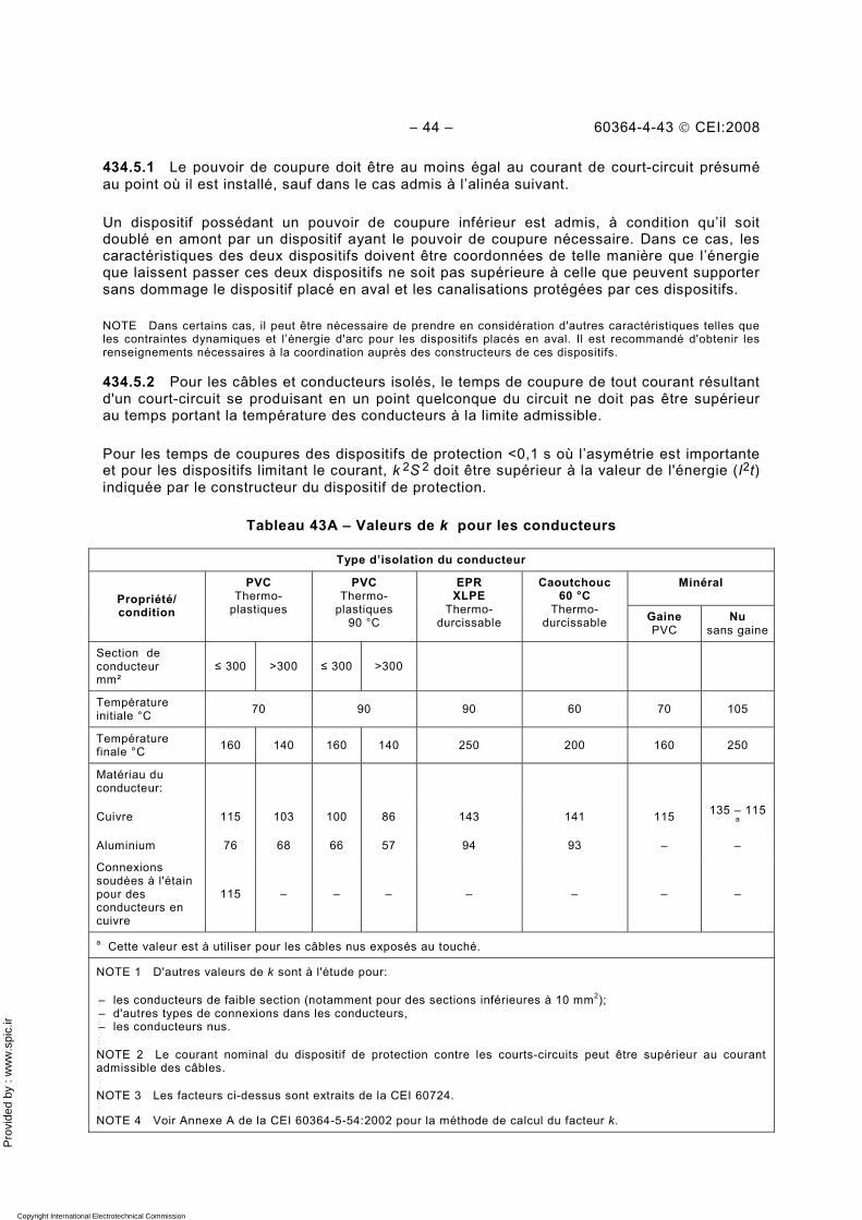
Pro
vide
d by
: w
ww
.spi
c.ir
– 44 – 60364-4-43 © CEI:2008
434.5.1 Le pouvoir de coupure doit être au moins égal au courant de court-circuit présumé au point où il est installé, sauf dans le cas admis à l’alinéa suivant.
Un dispositif possédant un pouvoir de coupure inférieur est admis, à condition qu’il soit doublé en amont par un dispositif ayant le pouvoir de coupure nécessaire. Dans ce cas, les caractéristiques des deux dispositifs doivent être coordonnées de telle manière que l’énergie que laissent passer ces deux dispositifs ne soit pas supérieure à celle que peuvent supporter sans dommage le dispositif placé en aval et les canalisations protégées par ces dispositifs.
NOTE Dans certains cas, il peut être nécessaire de prendre en considération d'autres caractéristiques telles que les contraintes dynamiques et l’énergie d'arc pour les dispositifs placés en aval. Il est recommandé d'obtenir les renseignements nécessaires à la coordination auprès des constructeurs de ces dispositifs.
434.5.2 Pour les câbles et conducteurs isolés, le temps de coupure de tout courant résultant d'un court-circuit se produisant en un point quelconque du circuit ne doit pas être supérieur au temps portant la température des conducteurs à la limite admissible.
Pour les temps de coupures des dispositifs de protection <0,1 s où l’asymétrie est importante et pour les dispositifs limitant le courant, k 2S 2 doit être supérieur à la valeur de l'énergie (I2t) indiquée par le constructeur du dispositif de protection.
Tableau 43A – Valeurs de k pour les conducteurs
Type d’isolation du conducteur
Minéral Propriété/ condition
PVC Thermo-
plastiques
PVC Thermo-
plastiques 90 °C
EPR XLPE
Thermo-durcissable
Caoutchouc 60 °C
Thermo-durcissable Gaine
PVC Nu
sans gaine
Section de conducteur mm²
≤ 300 >300 ≤ 300 >300
Température initiale °C 70 90 90 60 70 105
Température finale °C 160 140 160 140 250 200 160 250
Matériau du conducteur:
Cuivre 115 103 100 86 143 141 115 135 – 115 a
Aluminium 76 68 66 57 94 93 – –
Connexions soudées à l'étain pour des conducteurs en cuivre
115 – – – – – – –
a Cette valeur est à utiliser pour les câbles nus exposés au touché.
NOTE 1 D'autres valeurs de k sont à l'étude pour:
– les conducteurs de faible section (notamment pour des sections inférieures à 10 mm2); – d'autres types de connexions dans les conducteurs, – les conducteurs nus.
NOTE 2 Le courant nominal du dispositif de protection contre les courts-circuits peut être supérieur au courant admissible des câbles.
NOTE 3 Les facteurs ci-dessus sont extraits de la CEI 60724.
NOTE 4 Voir Annexe A de la CEI 60364-5-54:2002 pour la méthode de calcul du facteur k.
Copyright International Electrotechnical Commission Provided by IHS under license with IEC Licensee=Hong Kong Polytechnic Univ/9976803100
Not for Resale, 12/31/2010 02:47:20 MSTNo reproduction or networking permitted without license from IHS
--`,````,,,,,``,,,,,`,`,,`,`,`,`-`-`,,`,,`,`,,`---
Pro
vide
d by
: w
ww
.spi
c.ir
60364-4-43 © CEI:2008 – 45 –
Pour les courts-circuits d'une durée t au plus égale a 5 s, la durée nécessaire pour qu'un courant de court-circuit élève la température des conducteurs de la température maximale admissible en service normal à la valeur limite peut être calculée, en première approximation, à l’aide de la formule suivante:
2I) /S *kt (= (3)
où t est la durée, en s; S est la section des conducteurs, en mm2;
I est le courant effectif de court-circuit, en A, exprimé, pour l'alternatif, en valeur efficace; k est le facteur tenant compte de la résistivité, du coefficient de température et de la tenue
aux échauffements du matériau du conducteur, ainsi que des températures initiales et finales. Pour les isolations les plus communes des conducteurs, les valeurs de k pour les conducteurs de phase sont indiquées dans le Tableau 43A.
434.5.3 Pour les canalisations préfabriquées conforment à la CEI 60439-2 et les conducteurs préfabriqués conforment à la série CEI 61534, une des exigences suivantes doit être remplie:
• Le courant de courte durée assigné admissible (ICW) et le courant assigné de crête admissible d’un système de canalisations ou de conducteurs préfabriqués ne doivent pas être respectivement inférieurs au courant efficace de court-circuit présumé et au courant de crête de court-circuit présumé. Le temps maximal pour lequel ICW est défini pour les systèmes de canalisations ou de conducteurs préfabriqués ne doit pas être inférieur au temps maximal de coupure du dispositif de protection.
• Le courant de court-circuit assigné d’un système de canalisations ou de conducteurs préfabriqués ne doit pas être inférieur au courant de court-circuit présumé.
435 Coordination entre la protection contre les surcharges et la protection contre les courts-circuits
435.1 Protection assurée par le même dispositif
Un dispositif de protection assurant la protection contre les surcharges et contre les courts-circuits doit satisfaire aux exigences des Articles 433 et 434.
435.2 Protection assurée par des dispositifs distincts
Les exigences des Articles 433 et 434 s’appliquent, respectivement, au dispositif de protection contre les surcharges et au dispositif de protection contre les courts-circuits.
Les caractéristiques des dispositifs doivent être coordonnées de telle manière que l'énergie que laisse passer le dispositif de protection contre les courts-circuits ne soit pas supérieure à celle que peut supporter sans dommage le dispositif de protection contre les surcharges.
NOTE Cette exigence n'exclut pas les types de coordination spécifiés dans la CEI 60947-4-1.
436 Limitation des surintensités par les caractéristiques de l’alimentation
Sont réputés être protégés contre toute surintensité les conducteurs alimentés par une source dont le courant maximal qu'elle peut fournir ne peut pas être supérieur au courant admissible dans les conducteurs (tels que certains transformateurs de sonnerie, certains transformateurs de soudage, certaines génératrices entraînées par moteur thermique).
Copyright International Electrotechnical Commission Provided by IHS under license with IEC Licensee=Hong Kong Polytechnic Univ/9976803100
Not for Resale, 12/31/2010 02:47:20 MSTNo reproduction or networking permitted without license from IHS
--`,````,,,,,``,,,,,`,`,,`,`,`,`-`-`,,`,,`,`,,`---
Pro
vide
d by
: w
ww
.spi
c.ir
– 46 – 60364-4-43 © CEI:2008
Annexe A (informative)
Protection contre les surintensités des conducteurs en parallèle
A.1 Introduction
Il convient d’adapter la protection contre les surintensités des conducteurs en parallèle de manière à fournir une protection contre les surintensités appropriée à tous les conducteurs en parallèle. Pour deux conducteurs de même section, même longueur et même mode de pose, et parcourus par des courants quasi égaux, les exigences de protection contre les surintensités sont normales. Pour des dispositions plus complexes de conducteurs, il convient d’indiquer des considérations plus détaillées sur le partage inégal du courant et les divers cheminements de défauts multiples. Cette annexe donne des indications sur les aspects nécessaires à considérer.
NOTE Une méthode plus détaillée pour le calcul des courants entre des conducteurs parallèles est donnée dans la CEI 60287-1-3.
A.2 Protection contre les surcharges de conducteurs en parallèle
Si une surcharge se produit dans un circuit comprenant des conducteurs en parallèle dans un câble multiconducteur, le courant dans chaque conducteur augmentera proportionnellement. Pourvu que le courant soit partagé de manière égale entre les conducteurs en parallèle, un seul dispositif peut être utilisé pour la protection de tous les conducteurs. Le courant admissible (Iz) des conducteurs en parallèle est la somme des courants admissibles de chacun des conducteurs affectés par le facteur approprié de groupement et les autres facteurs applicables.
Le partage du courant entre les câbles en parallèle est fonction de l'impédance des câbles. Pour des câbles monoconducteurs de grande section, la composante réactive de l'impédance est supérieure à la composante résistive et aura un effet significatif sur le partage du courant. La composante réactive dépend de la position physique relative de chaque câble. Si, par exemple, un circuit composé de deux câbles de section importante par phase, de même longueur, de même construction et de même section et disposés en parallèle de manière défavorable (par exemple câbles de chaque phase groupés), le partage de courant peut être 70 %/30 % plutôt que 50 %/50 %.
Si la différence d'impédance entre les conducteurs parallèle entraîne un partage de courant très inégal, par exemple présentant une différence supérieure à 10 %, il est recommandé d’analyser individuellement la valeur du courant et les exigences relatives à la protection contre les surcharges de chaque conducteur.
Le courant de chaque conducteur peut être calculé à partir de la charge totale et de l'impédance de chaque conducteur.
Pour un nombre total de m conducteurs en parallèle, le courant IBK du conducteur k est donné par:
⎟⎟⎠
⎞⎜⎜⎝
⎛+⋅⋅⋅++++⋅⋅⋅++
=
+− m
k
1k
k
k
k
1k
k
2
k
1
k
BBk
ZZ
ZZ
ZZ
ZZ
ZZ
ZZ
II (A.1)
où IB est le courant d'emploi du circuit;
Copyright International Electrotechnical Commission Provided by IHS under license with IEC Licensee=Hong Kong Polytechnic Univ/9976803100
Not for Resale, 12/31/2010 02:47:20 MSTNo reproduction or networking permitted without license from IHS
--`,````,,,,,``,,,,,`,`,,`,`,`,`-`-`,,`,,`,`,,`---
Pro
vide
d by
: w
ww
.spi
c.ir
60364-4-43 © CEI:2008 – 47 –
IBK est le courant d’emploi du conducteur k; Zk est l’impédance du conducteur k ;
Z1 et Zm sont les impédances respectives des conducteurs 1 et m.
Dans le cas de conducteurs en parallèles de section inférieure ou égale à 120 mm2, le courant IBK du conducteur k est donné par:
m21
kBBk ... SSS
SII
+++= (A.2)
où
Sk est la section du conducteur k ;
S1 … Sm est la section des conducteurs.
Pour des câbles monoconducteurs, l'impédance dépend des positions relatives des câbles ainsi que de la conception du câble, par exemple armé ou non. Des méthodes de calculs de l'impédance sont donnée par la CEI 60287-1-3. Il est recommandé de vérifier par mesure le partage du courant entre des conducteurs en parallèle.
Le courant prévu IBK doit être utilisé à la place de IB pour l'Equation (1) de 433.1 comme indiqué ci-après:
IBk ≤ In ≤ Izk (A.3)
La valeur utilisée pour Iz dans 433.1, Équations (1) et (2) est
soit
le courant admissible de chaque conducteur, Izk,, si un dispositif de protection contre les surcharge est prévu pour chaque conducteur (voir Figure A.1), ainsi:
IBk ≤ Ink ≤ Izk (A.4)
soit
la somme des courants admissibles de chaque conducteur, ΣIzk, si un seul dispositif de protection contre les surcharges est prévu pour les conducteurs en parallèle (voir Figure A.2), ainsi:
IB ≤ In ≤ ΣIzk (A.5)
où
Ink est le courant nominal du dispositif de protection du conducteur k; Izk est le courant admissible du conducteur k; In est le courant assigné du dispositif de protection;
ΣIzk est la somme des courants admissibles des m conducteurs en parallèle.
NOTE Pour les canalisations préfabriquées, les informations peuvent être obtenues soient auprès des fabricants soit dans la CEI 60439-2.
Copyright International Electrotechnical Commission Provided by IHS under license with IEC Licensee=Hong Kong Polytechnic Univ/9976803100
Not for Resale, 12/31/2010 02:47:20 MSTNo reproduction or networking permitted without license from IHS
--`,````,,,,,``,,,,,`,`,,`,`,`,`-`-`,,`,,`,`,,`---
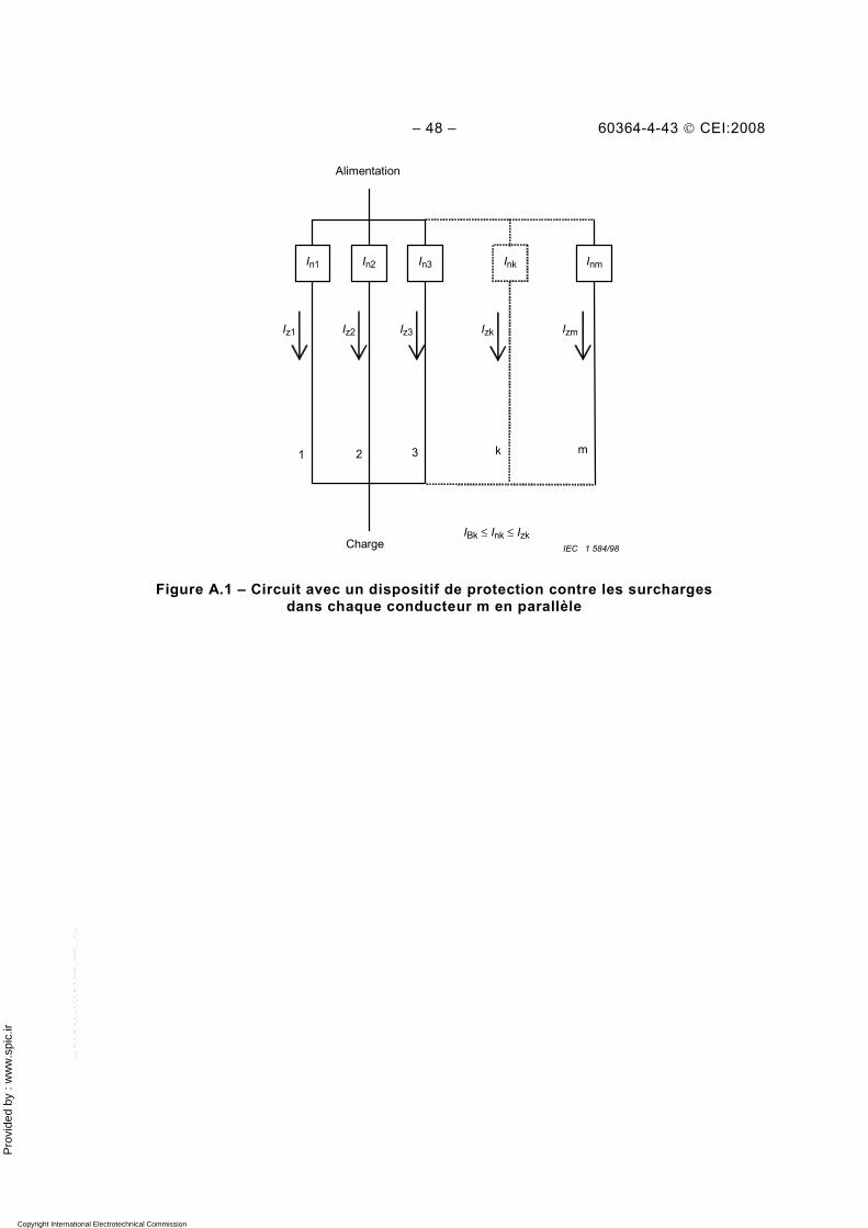
Pro
vide
d by
: w
ww
.spi
c.ir
– 48 – 60364-4-43 © CEI:2008
IEC 1 584/98 Charge
1 2 3
Inm Ink In3 In2 In1
IBk ≤ Ink ≤ Izk
Iz1 IzmIzkIz3Iz2
m
Alimentation
k
Figure A.1 – Circuit avec un dispositif de protection contre les surcharges dans chaque conducteur m en parallèle
Copyright International Electrotechnical Commission Provided by IHS under license with IEC Licensee=Hong Kong Polytechnic Univ/9976803100
Not for Resale, 12/31/2010 02:47:20 MSTNo reproduction or networking permitted without license from IHS
--`,````,,,,,``,,,,,`,`,,`,`,`,`-`-`,,`,,`,`,,`---
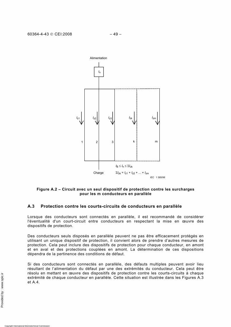
Pro
vide
d by
: w
ww
.spi
c.ir
60364-4-43 © CEI:2008 – 49 –
1 2 3
IzmIzkIz3Iz2
ΣIzk = Iz1 + Iz2 + ... + Izm
IB ≤ In ≤ ΣIzk
Iz1
mk
Alimentation
In
Charge IEC 1 585/98
Figure A.2 – Circuit avec un seul dispositif de protection contre les surcharges pour les m conducteurs en parallèle
A.3 Protection contre les courts-circuits de conducteurs en parallèle
Lorsque des conducteurs sont connectés en parallèle, il est recommandé de considérer l'éventualité d'un court-circuit entre conducteurs en respectant la mise en œuvre des dispositifs de protection.
Des conducteurs seuls disposés en parallèle peuvent ne pas être efficacement protégés en utilisant un unique dispositif de protection, il convient alors de prendre d’autres mesures de protection. Cela peut inclure des dispositifs de protection pour chaque conducteur, en amont et en aval et des protections couplées en amont. La détermination de ces dispositions dépendra de la pertinence des conditions de défaut.
Si des conducteurs sont connectés en parallèle, des défauts multiples peuvent avoir lieu résultant de l’alimentation du défaut par une des extrémités du conducteur. Cela peut être résolu en mettant en œuvre des dispositifs de protection contre les courts-circuits à chaque extrémité de chaque conducteur en parallèle. Cette situation est illustrée dans les Figures A.3 et A.4.
Copyright International Electrotechnical Commission Provided by IHS under license with IEC Licensee=Hong Kong Polytechnic Univ/9976803100
Not for Resale, 12/31/2010 02:47:20 MSTNo reproduction or networking permitted without license from IHS
--`,````,,,,,``,,,,,`,`,,`,`,`,`-`-`,,`,,`,`,,`---
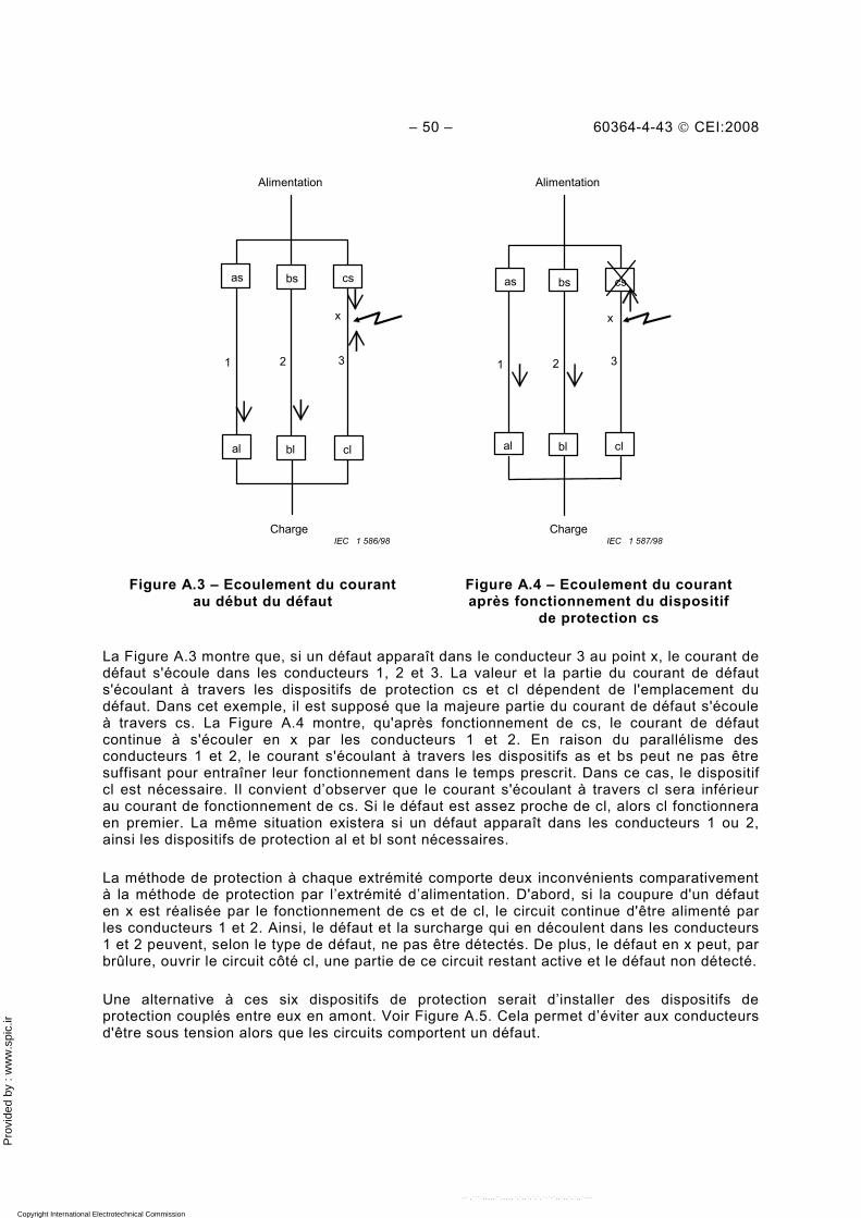
Pro
vide
d by
: w
ww
.spi
c.ir
– 50 – 60364-4-43 © CEI:2008
1 2 3
x
bs cs as
bl cl al
1 2 3
x
bs cs as
bl cl al
Charge Charge
AlimentationAlimentation
IEC 1 587/98 IEC 1 586/98
Figure A.3 – Ecoulement du courant au début du défaut
Figure A.4 – Ecoulement du courant après fonctionnement du dispositif
de protection cs
La Figure A.3 montre que, si un défaut apparaît dans le conducteur 3 au point x, le courant de défaut s'écoule dans les conducteurs 1, 2 et 3. La valeur et la partie du courant de défaut s'écoulant à travers les dispositifs de protection cs et cl dépendent de l'emplacement du défaut. Dans cet exemple, il est supposé que la majeure partie du courant de défaut s'écoule à travers cs. La Figure A.4 montre, qu'après fonctionnement de cs, le courant de défaut continue à s'écouler en x par les conducteurs 1 et 2. En raison du parallélisme des conducteurs 1 et 2, le courant s'écoulant à travers les dispositifs as et bs peut ne pas être suffisant pour entraîner leur fonctionnement dans le temps prescrit. Dans ce cas, le dispositif cl est nécessaire. Il convient d’observer que le courant s'écoulant à travers cl sera inférieur au courant de fonctionnement de cs. Si le défaut est assez proche de cl, alors cl fonctionnera en premier. La même situation existera si un défaut apparaît dans les conducteurs 1 ou 2, ainsi les dispositifs de protection al et bl sont nécessaires.
La méthode de protection à chaque extrémité comporte deux inconvénients comparativement à la méthode de protection par l’extrémité d’alimentation. D'abord, si la coupure d'un défaut en x est réalisée par le fonctionnement de cs et de cl, le circuit continue d'être alimenté par les conducteurs 1 et 2. Ainsi, le défaut et la surcharge qui en découlent dans les conducteurs 1 et 2 peuvent, selon le type de défaut, ne pas être détectés. De plus, le défaut en x peut, par brûlure, ouvrir le circuit côté cl, une partie de ce circuit restant active et le défaut non détecté.
Une alternative à ces six dispositifs de protection serait d’installer des dispositifs de protection couplés entre eux en amont. Voir Figure A.5. Cela permet d’éviter aux conducteurs d'être sous tension alors que les circuits comportent un défaut.
Copyright International Electrotechnical Commission Provided by IHS under license with IEC Licensee=Hong Kong Polytechnic Univ/9976803100
Not for Resale, 12/31/2010 02:47:20 MSTNo reproduction or networking permitted without license from IHS
--`,````,,,,,``,,,,,`,`,,`,`,`,`-`-`,,`,,`,`,,`---
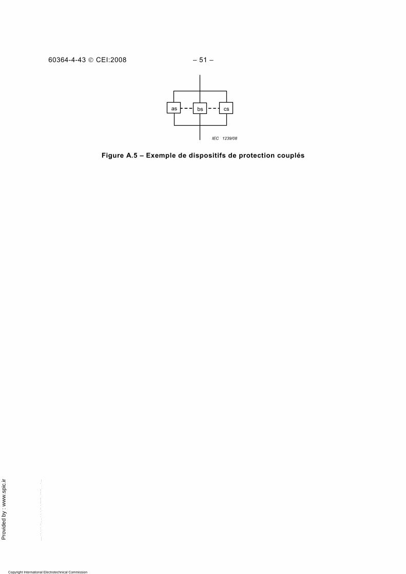
Pro
vide
d by
: w
ww
.spi
c.ir
60364-4-43 © CEI:2008 – 51 –
bs cs as
IEC 1239/08
Figure A.5 – Exemple de dispositifs de protection couplés
Copyright International Electrotechnical Commission Provided by IHS under license with IEC Licensee=Hong Kong Polytechnic Univ/9976803100
Not for Resale, 12/31/2010 02:47:20 MSTNo reproduction or networking permitted without license from IHS
--`,````,,,,,``,,,,,`,`,,`,`,`,`-`-`,,`,,`,`,,`---
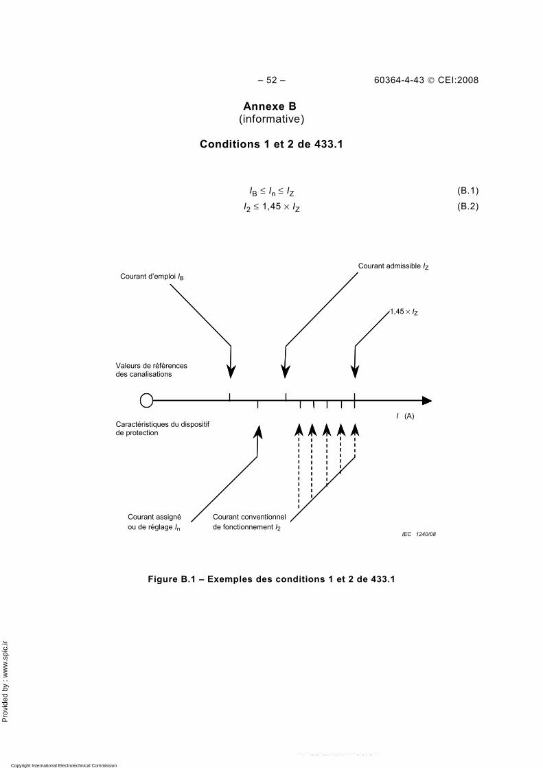
Pro
vide
d by
: w
ww
.spi
c.ir
– 52 – 60364-4-43 © CEI:2008
Annexe B (informative)
Conditions 1 et 2 de 433.1
IB ≤ In ≤ IZ (B.1)
I2 ≤ 1,45 × IZ (B.2)
Courant d’emploi IB Courant admissible IZ
1,45 × IZ
Valeurs de références des canalisations
Caractéristiques du dispositif de protection
Courant assigné ou de réglage In
Courant conventionnel de fonctionnement I2
I (A)
IEC 1240/08
Figure B.1 – Exemples des conditions 1 et 2 de 433.1
Copyright International Electrotechnical Commission Provided by IHS under license with IEC Licensee=Hong Kong Polytechnic Univ/9976803100
Not for Resale, 12/31/2010 02:47:20 MSTNo reproduction or networking permitted without license from IHS
--`,````,,,,,``,,,,,`,`,,`,`,`,`-`-`,,`,,`,`,,`---
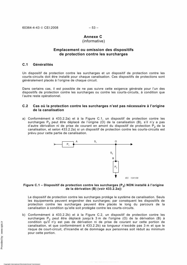
Pro
vide
d by
: w
ww
.spi
c.ir
60364-4-43 © CEI:2008 – 53 –
Annexe C (informative)
Emplacement ou omission des dispositifs
de protection contre les surcharges
C.1 Généralités
Un dispositif de protection contre les surcharges et un dispositif de protection contre les courts-circuits doit être installé pour chaque canalisation. Ces dispositifs de protections sont généralement placés à l’origine de chaque circuit.
Dans certains cas, il est possible de ne pas suivre cette exigence générale pour l’un des dispositifs de protection contre les surcharges ou contre les courts-circuits, à condition que l’autre reste opérationnel.
C.2 Cas où la protection contre les surcharges n’est pas nécessaire à l’origine de la canalisation
a) Conformément à 433.2.2a) et à la Figure C.1, un dispositif de protection contre les surcharges P2 peut être déplacé de l’origine (O) de la canalisation (B), s’il n’y a pas d’autre dérivation ni de prise de courant en amont du dispositif de protection P2 de la canalisation, et selon 433.2.2a) si un dispositif de protection contre les courts-circuits est prévu pour cette partie de canalisation.
A
B
OS1
S2
P1
P2
Figure C.1 – Dispositif de protection contre les surcharges (P2) NON installé à l’origine
de la dérivation (B) (voir 433.2.2a))
Le dispositif de protection contre les surcharges protège le système de canalisation. Seuls les équipements peuvent engendrer des surcharges; par conséquent les dispositifs de protection contre les surcharges peuvent être placés le long du parcours de la canalisation à condition qu’elle soit protégée contre les courts-circuits.
b) Conformément à 433.2.2b) et à la Figure C.2, un dispositif de protection contre les surcharges P2 peut être déplacé jusqu’à 3 m de l'origine (O) de la dérivation (B) à condition qu'il n'y est pas de dérivation ni de prise de courant sur cette portion de canalisation, et que conformément à 433.2.2b) sa longueur n’excède pas 3 m et que le risque de court-circuit, d'incendie et de dommage aux personnes soit réduit au minimum pour cette portion.
IEC 1241/08
Copyright International Electrotechnical Commission Provided by IHS under license with IEC Licensee=Hong Kong Polytechnic Univ/9976803100
Not for Resale, 12/31/2010 02:47:20 MSTNo reproduction or networking permitted without license from IHS
--`,````,,,,,``,,,,,`,`,,`,`,`,`-`-`,,`,,`,`,,`---
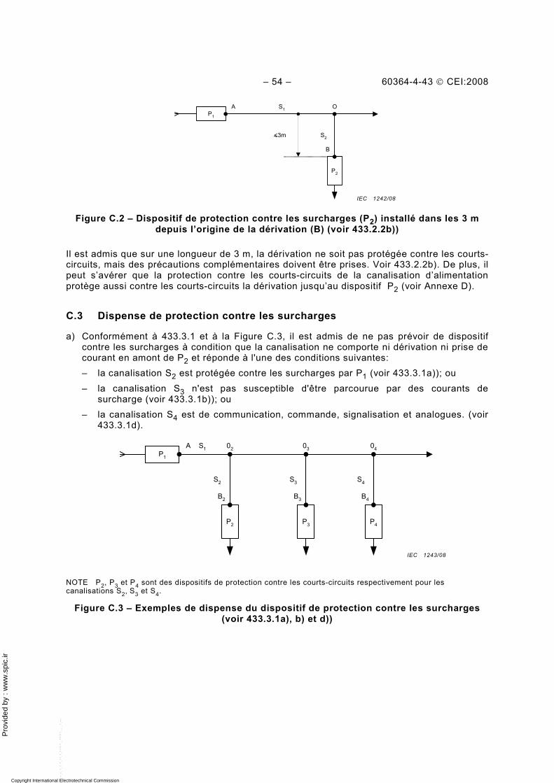
Pro
vide
d by
: w
ww
.spi
c.ir
– 54 – 60364-4-43 © CEI:2008
A
B
OS1
S2
P1
P2
<3m
Figure C.2 – Dispositif de protection contre les surcharges (P2) installé dans les 3 m
depuis l’origine de la dérivation (B) (voir 433.2.2b))
Il est admis que sur une longueur de 3 m, la dérivation ne soit pas protégée contre les courts-circuits, mais des précautions complémentaires doivent être prises. Voir 433.2.2b). De plus, il peut s’avérer que la protection contre les courts-circuits de la canalisation d’alimentation protège aussi contre les courts-circuits la dérivation jusqu’au dispositif P2 (voir Annexe D).
C.3 Dispense de protection contre les surcharges
a) Conformément à 433.3.1 et à la Figure C.3, il est admis de ne pas prévoir de dispositif contre les surcharges à condition que la canalisation ne comporte ni dérivation ni prise de courant en amont de P2 et réponde à l'une des conditions suivantes: – la canalisation S2 est protégée contre les surcharges par P1 (voir 433.3.1a)); ou – la canalisation S3 n'est pas susceptible d'être parcourue par des courants de
surcharge (voir 433.3.1b)); ou – la canalisation S4 est de communication, commande, signalisation et analogues. (voir
433.3.1d).
A S1
S3
P1
P3
02
S2
P2
S4
P4
03 04
B2 B3 B4
NOTE P2, P3 et P4 sont des dispositifs de protection contre les courts-circuits respectivement pour les canalisations S2, S3 et S4.
Figure C.3 – Exemples de dispense du dispositif de protection contre les surcharges (voir 433.3.1a), b) et d))
IEC 1242/08
IEC 1243/08
Copyright International Electrotechnical Commission Provided by IHS under license with IEC Licensee=Hong Kong Polytechnic Univ/9976803100
Not for Resale, 12/31/2010 02:47:20 MSTNo reproduction or networking permitted without license from IHS
--`,````,,,,,``,,,,,`,`,,`,`,`,`-`-`,,`,,`,`,,`---
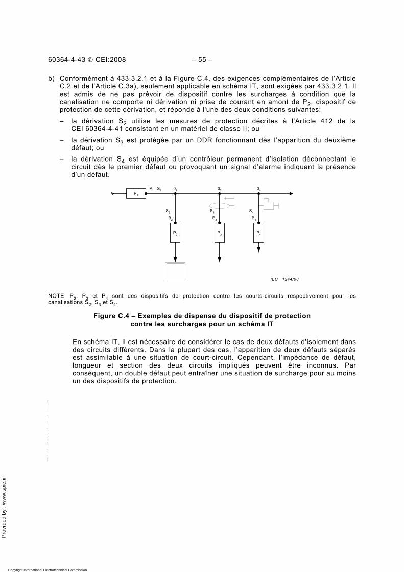
Pro
vide
d by
: w
ww
.spi
c.ir
60364-4-43 © CEI:2008 – 55 –
b) Conformément à 433.3.2.1 et à la Figure C.4, des exigences complémentaires de l’Article C.2 et de l’Article C.3a), seulement applicable en schéma IT, sont exigées par 433.3.2.1. Il est admis de ne pas prévoir de dispositif contre les surcharges à condition que la canalisation ne comporte ni dérivation ni prise de courant en amont de P2, dispositif de protection de cette dérivation, et réponde à l'une des deux conditions suivantes: – la dérivation S2 utilise les mesures de protection décrites à l’Article 412 de la
CEI 60364-4-41 consistant en un matériel de classe II; ou – la dérivation S3 est protégée par un DDR fonctionnant dès l’apparition du deuxième
défaut; ou – la dérivation S4 est équipée d’un contrôleur permanent d’isolation déconnectant le
circuit dès le premier défaut ou provoquant un signal d’alarme indiquant la présence d’un défaut.
A S1
S3
P1
P3
02
S2
P2
S4
P4
03 04
B2 B3 B4
NOTE P2, P3 et P4 sont des dispositifs de protection contre les courts-circuits respectivement pour les canalisations S2, S3 et S4.
Figure C.4 – Exemples de dispense du dispositif de protection contre les surcharges pour un schéma IT
En schéma IT, il est nécessaire de considérer le cas de deux défauts d'isolement dans des circuits différents. Dans la plupart des cas, l’apparition de deux défauts séparés est assimilable à une situation de court-circuit. Cependant, l’impédance de défaut, longueur et section des deux circuits impliqués peuvent être inconnus. Par conséquent, un double défaut peut entraîner une situation de surcharge pour au moins un des dispositifs de protection.
IEC 1244/08
Copyright International Electrotechnical Commission Provided by IHS under license with IEC Licensee=Hong Kong Polytechnic Univ/9976803100
Not for Resale, 12/31/2010 02:47:20 MSTNo reproduction or networking permitted without license from IHS
--`,````,,,,,``,,,,,`,`,,`,`,`,`-`-`,,`,,`,`,,`---
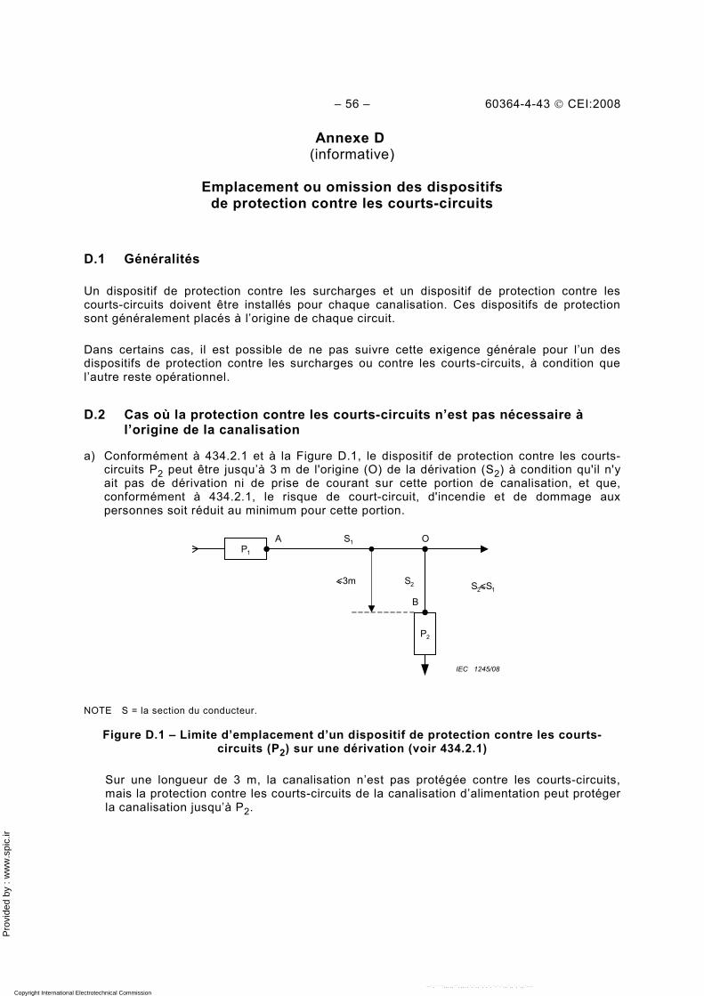
Pro
vide
d by
: w
ww
.spi
c.ir
– 56 – 60364-4-43 © CEI:2008
Annexe D (informative)
Emplacement ou omission des dispositifs
de protection contre les courts-circuits
D.1 Généralités
Un dispositif de protection contre les surcharges et un dispositif de protection contre les courts-circuits doivent être installés pour chaque canalisation. Ces dispositifs de protection sont généralement placés à l’origine de chaque circuit.
Dans certains cas, il est possible de ne pas suivre cette exigence générale pour l’un des dispositifs de protection contre les surcharges ou contre les courts-circuits, à condition que l’autre reste opérationnel.
D.2 Cas où la protection contre les courts-circuits n’est pas nécessaire à l’origine de la canalisation
a) Conformément à 434.2.1 et à la Figure D.1, le dispositif de protection contre les courts-circuits P2 peut être jusqu’à 3 m de l'origine (O) de la dérivation (S2) à condition qu'il n'y ait pas de dérivation ni de prise de courant sur cette portion de canalisation, et que, conformément à 434.2.1, le risque de court-circuit, d'incendie et de dommage aux personnes soit réduit au minimum pour cette portion.
A
B
OS1
S2
P 1
P2
S2<S1<3m
IEC 1245/08
NOTE S = la section du conducteur.
Figure D.1 – Limite d’emplacement d’un dispositif de protection contre les courts-circuits (P2) sur une dérivation (voir 434.2.1)
Sur une longueur de 3 m, la canalisation n’est pas protégée contre les courts-circuits, mais la protection contre les courts-circuits de la canalisation d’alimentation peut protéger la canalisation jusqu’à P2.
Copyright International Electrotechnical Commission Provided by IHS under license with IEC Licensee=Hong Kong Polytechnic Univ/9976803100
Not for Resale, 12/31/2010 02:47:20 MSTNo reproduction or networking permitted without license from IHS
--`,````,,,,,``,,,,,`,`,,`,`,`,`-`-`,,`,,`,`,,`---
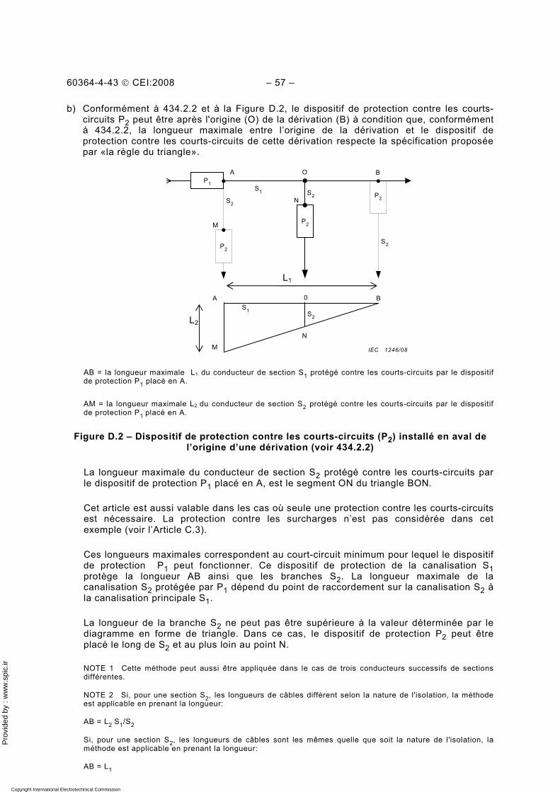
Pro
vide
d by
: w
ww
.spi
c.ir
60364-4-43 © CEI:2008 – 57 –
b) Conformément à 434.2.2 et à la Figure D.2, le dispositif de protection contre les courts-circuits P2 peut être après l'origine (O) de la dérivation (B) à condition que, conformément à 434.2.2, la longueur maximale entre l’origine de la dérivation et le dispositif de protection contre les courts-circuits de cette dérivation respecte la spécification proposée par «la règle du triangle».
AB = la longueur maximale L1 du conducteur de section S1 protégé contre les courts-circuits par le dispositif de protection P1 placé en A.
AM = la longueur maximale L2 du conducteur de section S2 protégé contre les courts-circuits par le dispositif de protection P1 placé en A.
Figure D.2 – Dispositif de protection contre les courts-circuits (P2) installé en aval de l’origine d’une dérivation (voir 434.2.2)
La longueur maximale du conducteur de section S2 protégé contre les courts-circuits par le dispositif de protection P1 placé en A, est le segment ON du triangle BON.
Cet article est aussi valable dans les cas où seule une protection contre les courts-circuits est nécessaire. La protection contre les surcharges n’est pas considérée dans cet exemple (voir l’Article C.3).
Ces longueurs maximales correspondent au court-circuit minimum pour lequel le dispositif de protection P1 peut fonctionner. Ce dispositif de protection de la canalisation S1 protège la longueur AB ainsi que les branches S2. La longueur maximale de la canalisation S2 protégée par P1 dépend du point de raccordement sur la canalisation S2 à la canalisation principale S1.
La longueur de la branche S2 ne peut pas être supérieure à la valeur déterminée par le diagramme en forme de triangle. Dans ce cas, le dispositif de protection P2 peut être placé le long de S2 et au plus loin au point N.
NOTE 1 Cette méthode peut aussi être appliquée dans le cas de trois conducteurs successifs de sections différentes.
NOTE 2 Si, pour une section S2, les longueurs de câbles diffèrent selon la nature de l'isolation, la méthode est applicable en prenant la longueur:
AB = L2 S1/S2
Si, pour une section S2, les longueurs de câbles sont les mêmes quelle que soit la nature de l'isolation, la méthode est applicable en prenant la longueur:
AB = L1
A
S1 S2
P 1
P2
B0
S2
S1
S2
P2
P 2
M
S 2P2
O B
N
M
A
N
L1
L2
IEC 1246/08
Copyright International Electrotechnical Commission Provided by IHS under license with IEC Licensee=Hong Kong Polytechnic Univ/9976803100
Not for Resale, 12/31/2010 02:47:20 MSTNo reproduction or networking permitted without license from IHS
--`,````,,,,,``,,,,,`,`,,`,`,`,`-`-`,,`,,`,`,,`---
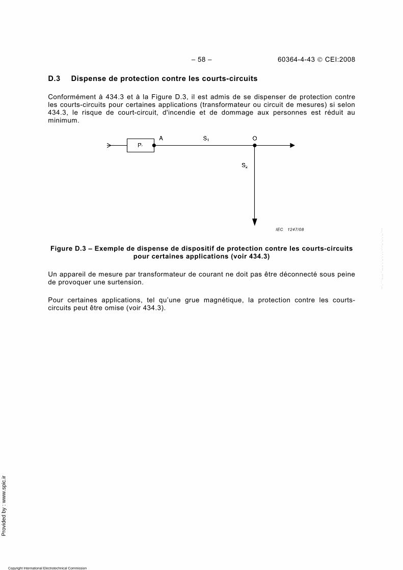
Pro
vide
d by
: w
ww
.spi
c.ir
– 58 – 60364-4-43 © CEI:2008
D.3 Dispense de protection contre les courts-circuits
Conformément à 434.3 et à la Figure D.3, il est admis de se dispenser de protection contre les courts-circuits pour certaines applications (transformateur ou circuit de mesures) si selon 434.3, le risque de court-circuit, d'incendie et de dommage aux personnes est réduit au minimum.
Figure D.3 – Exemple de dispense de dispositif de protection contre les courts-circuits pour certaines applications (voir 434.3)
Un appareil de mesure par transformateur de courant ne doit pas être déconnecté sous peine de provoquer une surtension.
Pour certaines applications, tel qu’une grue magnétique, la protection contre les courts-circuits peut être omise (voir 434.3).
IEC 1247/08
Copyright International Electrotechnical Commission Provided by IHS under license with IEC Licensee=Hong Kong Polytechnic Univ/9976803100
Not for Resale, 12/31/2010 02:47:20 MSTNo reproduction or networking permitted without license from IHS
--`,````,,,,,``,,,,,`,`,,`,`,`,`-`-`,,`,,`,`,,`---
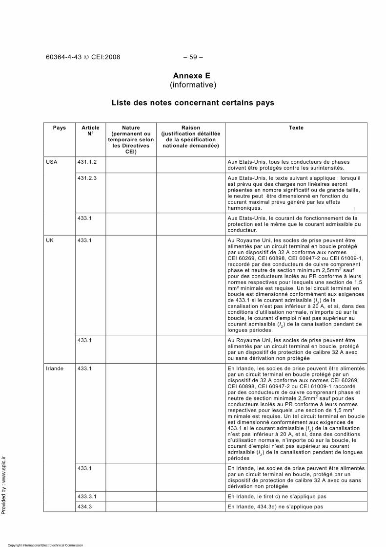
Pro
vide
d by
: w
ww
.spi
c.ir
60364-4-43 © CEI:2008 – 59 –
Annexe E (informative)
Liste des notes concernant certains pays
Pays Article N°
Nature (permanent ou
temporaire selon les Directives
CEI)
Raison (justification détaillée
de la spécification nationale demandée)
Texte
431.1.2 Aux Etats-Unis, tous les conducteurs de phases doivent être protégés contre les surintensités.
431.2.3 Aux Etats-Unis, le texte suivant s’applique : lorsqu’il est prévu que des charges non linéaires seront présentes en nombre significatif ou de grande taille, le neutre peut être dimensionné en fonction du courant maximal prévu généré par les effets harmoniques.
USA
433.1 Aux Etats-Unis, le courant de fonctionnement de la protection est le même que le courant admissible du conducteur.
433.1 Au Royaume Uni, les socles de prise peuvent être alimentés par un circuit terminal en boucle protégé par un dispositif de 32 A conforme aux normes CEI 60269, CEI 60898, CEI 60947-2 ou CEI 61009-1, raccordé par des conducteurs de cuivre comprenant phase et neutre de section minimum 2,5mm2 sauf pour des conducteurs isolés au PR conforme à leurs normes respectives pour lesquels une section de 1,5 mm² minimale est requise. Un tel circuit terminal en boucle est dimensionné conformément aux exigences de 433.1 si le courant admissible (Iz) de la canalisation n’est pas inférieur à 20 A, et si, dans des conditions d’utilisation normale, n’importe où sur la boucle, le courant d’emploi n’est pas supérieur au courant admissible (Iz) de la canalisation pendant de longues périodes.
UK
433.1 Au Royaume Uni, les socles de prise peuvent être alimentés par un circuit terminal en boucle, protégé par un dispositif de protection de calibre 32 A avec ou sans dérivation non protégée
433.1 En Irlande, les socles de prise peuvent être alimentés par un circuit terminal en boucle protégé par un dispositif de 32 A conforme aux normes CEI 60269, CEI 60898, CEI 60947-2 ou CEI 61009-1 raccordé par des conducteurs de cuivre comprenant phase et neutre de section minimale 2,5mm2 sauf pour des conducteurs isolés au PR conforme à leurs normes respectives pour lesquels une section de 1,5 mm² minimale est requise. Un tel circuit terminal en boucle est dimensionné conformément aux exigences de 433.1 si le courant admissible (Iz) de la canalisation n’est pas inférieur à 20 A, et si, dans des conditions d’utilisation normale, n’importe où sur la boucle, le courant d’emploi n’est pas supérieur au courant admissible (Iz) de la canalisation pendant de longues périodes
433.1 En Irlande, les socles de prise peuvent être alimentés par un circuit terminal en boucle, protégé par un dispositif de protection de calibre 32 A avec ou sans dérivation non protégée
433.3.1 En Irlande, le tiret c) ne s’applique pas
Irlande
434.3 En Irlande, 434.3d) ne s’applique pas
Copyright International Electrotechnical Commission Provided by IHS under license with IEC Licensee=Hong Kong Polytechnic Univ/9976803100
Not for Resale, 12/31/2010 02:47:20 MSTNo reproduction or networking permitted without license from IHS
--`,````,,,,,``,,,,,`,`,,`,`,`,`-`-`,,`,,`,`,,`---
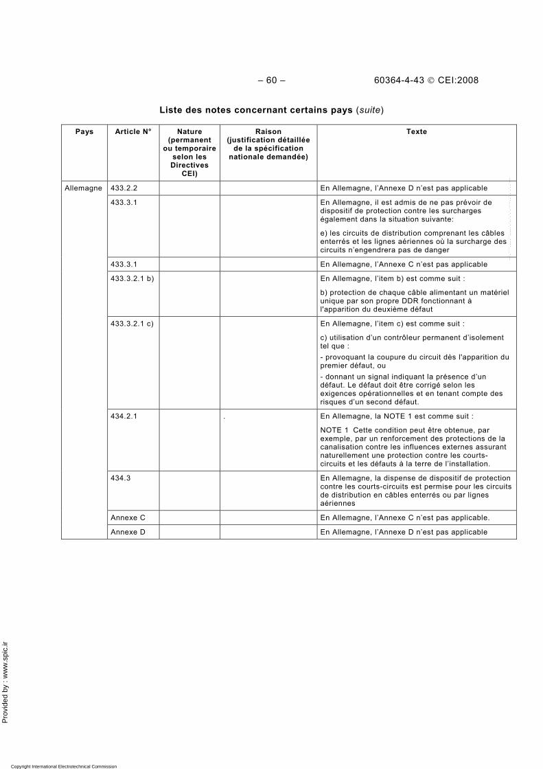
Pro
vide
d by
: w
ww
.spi
c.ir
– 60 – 60364-4-43 © CEI:2008
Liste des notes concernant certains pays (suite)
Pays Article N° Nature (permanent
ou temporaire selon les
Directives CEI)
Raison (justification détaillée
de la spécification nationale demandée)
Texte
433.2.2 En Allemagne, l’Annexe D n’est pas applicable
433.3.1 En Allemagne, il est admis de ne pas prévoir de dispositif de protection contre les surcharges également dans la situation suivante:
e) les circuits de distribution comprenant les câbles enterrés et les lignes aériennes où la surcharge des circuits n’engendrera pas de danger
433.3.1 En Allemagne, l’Annexe C n’est pas applicable
433.3.2.1 b) En Allemagne, l’item b) est comme suit :
b) protection de chaque câble alimentant un matériel unique par son propre DDR fonctionnant à l'apparition du deuxième défaut
433.3.2.1 c) En Allemagne, l’item c) est comme suit :
c) utilisation d’un contrôleur permanent d’isolement tel que : - provoquant la coupure du circuit dès l'apparition du premier défaut, ou - donnant un signal indiquant la présence d’un défaut. Le défaut doit être corrigé selon les exigences opérationnelles et en tenant compte des risques d’un second défaut.
434.2.1 .
En Allemagne, la NOTE 1 est comme suit :
NOTE 1 Cette condition peut être obtenue, par exemple, par un renforcement des protections de la canalisation contre les influences externes assurant naturellement une protection contre les courts-circuits et les défauts à la terre de l’installation.
434.3 En Allemagne, la dispense de dispositif de protection contre les courts-circuits est permise pour les circuits de distribution en câbles enterrés ou par lignes aériennes
Annexe C En Allemagne, l’Annexe C n’est pas applicable.
Allemagne
Annexe D En Allemagne, l’Annexe D n’est pas applicable
Copyright International Electrotechnical Commission Provided by IHS under license with IEC Licensee=Hong Kong Polytechnic Univ/9976803100
Not for Resale, 12/31/2010 02:47:20 MSTNo reproduction or networking permitted without license from IHS
--`,````,,,,,``,,,,,`,`,,`,`,`,`-`-`,,`,,`,`,,`---
Pro
vide
d by
: w
ww
.spi
c.ir
60364-4-43 © CEI:2008 – 61 –
Bibliographie
CEI 60269-1: Fusibles basse tension – Partie 1: Exigences générales
CEI 60287-1-3, Câbles électriques – Calcul du courant admissible – Partie 1-3: Equations de l’intensité du courant admissible (facteur de charge 100 %) et calcul des pertes – Répartition du courant entre des câbles unipolaires disposés en parallèle et calcul des pertes par courant de circulation
CEI 60364-5-54:2002, Installations électriques des bâtiments – Partie 5-54: Choix et mise en oeuvre des matériels électriques – Mises à la terre, conducteurs de protection et conducteurs d'équipotentialité de protection
CEI 60439-2, Ensembles d'appareillage à basse tension – Partie 2 : Règles particulières pour les canalisations préfabriquées
CEI 60947-1: Appareillage à basse tension – Partie 1: Règles générales
CEI 60947-4-1, Appareillage à basse tension – Partie 4-1: Contacteurs et démarreurs de moteurs - Contacteurs et démarreurs électromécaniques
CEI 61557-9, Sécurité électrique dans les réseaux de distribution basse tension de 1 000 V c.a. et 1 500 V c.c. – Dispositifs de contrôle, de mesure ou de surveillance de mesures de protection – Partie 9: Dispositifs de localisation de défauts d'isolement pour réseaux IT
___________
Copyright International Electrotechnical Commission Provided by IHS under license with IEC Licensee=Hong Kong Polytechnic Univ/9976803100
Not for Resale, 12/31/2010 02:47:20 MSTNo reproduction or networking permitted without license from IHS
--`,````,,,,,``,,,,,`,`,,`,`,`,`-`-`,,`,,`,`,,`---

Pro
vide
d by
: w
ww
.spi
c.ir
Copyright International Electrotechnical Commission Provided by IHS under license with IEC Licensee=Hong Kong Polytechnic Univ/9976803100
Not for Resale, 12/31/2010 02:47:20 MSTNo reproduction or networking permitted without license from IHS
--`,````,,,,,``,,,,,`,`,,`,`,`,`-`-`,,`,,`,`,,`---

Pro
vide
d by
: w
ww
.spi
c.ir
Copyright International Electrotechnical Commission Provided by IHS under license with IEC Licensee=Hong Kong Polytechnic Univ/9976803100
Not for Resale, 12/31/2010 02:47:20 MSTNo reproduction or networking permitted without license from IHS
--`,````,,,,,``,,,,,`,`,,`,`,`,`-`-`,,`,,`,`,,`---
Pro
vide
d by
: w
ww
.spi
c.ir
INTERNATIONAL ELECTROTECHNICAL COMMISSION 3, rue de Varembé PO Box 131 CH-1211 Geneva 20 Switzerland Tel: + 41 22 919 02 11 Fax: + 41 22 919 03 00 [email protected] www.iec.ch
Copyright International Electrotechnical Commission Provided by IHS under license with IEC Licensee=Hong Kong Polytechnic Univ/9976803100
Not for Resale, 12/31/2010 02:47:20 MSTNo reproduction or networking permitted without license from IHS
--`,````,,,,,``,,,,,`,`,,`,`,`,`-`-`,,`,,`,`,,`---