Embed Size (px)
Citation preview
EUROPEAN STANDARD
NORME EUROPÉENNE
EUROPÄISCHE NORM
EN 13779
April 2007
ICS 91.140.30 Supersedes EN 13779:2004
English Version
Ventilation for non-residential buildings - Performancerequirements for ventilation and room-conditioning systems
Ventilation dans les bâtiments non résidentiels - Exigencesde performances pour les systèmes de ventilation et de
climatisation
Lüftung von Nichtwohngebäuden - Allgemeine Grundlagenund Anforderungen für Lüftungs- und Klimaanlagen
This European Standard was approved by CEN on 26 March 2007.
CEN members are bound to comply with the CEN/CENELEC Internal Regulations which stipulate the conditions for giving this EuropeanStandard the status of a national standard without any alteration. Up-to-date lists and bibliographical references concerning such nationalstandards may be obtained on application to the CEN Management Centre or to any CEN member.
This European Standard exists in three official versions (English, French, German). A version in any other language made by translationunder the responsibility of a CEN member into its own language and notified to the CEN Management Centre has the same status as theofficial versions.
CEN members are the national standards bodies of Austria, Belgium, Bulgaria, Cyprus, Czech Republic, Denmark, Estonia, Finland,France, Germany, Greece, Hungary, Iceland, Ireland, Italy, Latvia, Lithuania, Luxembourg, Malta, Netherlands, Norway, Poland, Portugal,Romania, Slovakia, Slovenia, Spain, Sweden, Switzerland and United Kingdom.
EUROPEAN COMMITTEE FOR STANDARDIZATIONC OM ITÉ EUR OP ÉEN DE NOR M ALIS AT IONEUROPÄISCHES KOMITEE FÜR NORMUNG
Management Centre: rue de Stassart, 36 B-1050 Brussels
© 2007 CEN All rights of exploitation in any form and by any means reservedworldwide for CEN national Members.
Ref. No. EN 13779:2007: E
EN 13779:2007 (E)
2
Contents Page
Foreword............................................................................................................................................................. 4 Introduction ........................................................................................................................................................ 5 1 Scope...................................................................................................................................................... 6 2 Normative references ........................................................................................................................... 6 3 Terms and definitions........................................................................................................................... 7 4 Symbols and units ................................................................................................................................ 9 5 Agreement of design criteria ............................................................................................................. 10 5.1 General ................................................................................................................................................. 10 5.2 Principles ............................................................................................................................................. 10 5.3 General building characteristics ....................................................................................................... 10 5.4 Construction data ............................................................................................................................... 11 5.5 Geometrical description ..................................................................................................................... 11 5.6 Use of the rooms................................................................................................................................. 11 5.7 Requirements in the rooms ............................................................................................................... 12 5.8 System requirements.......................................................................................................................... 13 5.9 General requirements for control and monitoring .......................................................................... 13 5.10 General requirements for maintenance and safety of operation ................................................... 13 5.11 Process from project initiation to operation .................................................................................... 14 6 Classification....................................................................................................................................... 14 6.1 Specification of types of air ............................................................................................................... 14 6.2 Classification of air ............................................................................................................................. 16 6.3 System tasks and basic system types.............................................................................................. 21 6.4 Pressure conditions in the room....................................................................................................... 22 6.5 Specific fan power .............................................................................................................................. 23 6.6 Heat recovery ...................................................................................................................................... 24 7 Indoor environment ............................................................................................................................ 24 7.1 General ................................................................................................................................................. 24 7.2 Occupied zone..................................................................................................................................... 25 7.3 Thermal environment.......................................................................................................................... 27 7.4 Indoor air quality ................................................................................................................................. 28 7.5 Indoor air humidity.............................................................................................................................. 30 7.6 Acoustic environment ........................................................................................................................ 31 Annex A (informative) Guidelines for Good Practice.................................................................................... 32 Annex B (informative) Economic aspects...................................................................................................... 60
EN 13779:2007 (E)
3
Annex C (informative) Checklist for the design and use of systems with low energy consumption........................................................................................................................................ 61
Annex D (informative) Calculation and application of Specific Fan Power Calculating and checking the SFP, SFPE, and SFPV ................................................................................................... 64
Annex E (informative) Efficiency of ventilation and air diffusion................................................................ 71 Bibliography ..................................................................................................................................................... 72

EN 13779:2007 (E)
4
Foreword
This document (EN 13779:2007) has been prepared by Technical Committee CEN/TC 156 “Ventilation for buildings”, the secretariat of which is held by BSI.
This European Standard shall be given the status of a national standard, either by publication of an identical text or by endorsement, at the latest by October 2007, and conflicting national standards shall be withdrawn at the latest by October 2007.
This document supersedes EN 13779:2004.
This standard has been prepared under a mandate given to CEN by the European Commission and the European Free Trade Association (Mandate M/343), and supports essential requirements of EU Directive 2002/91/EC on the energy performance of buildings (EPBD). It forms part of a series of standards aimed at European harmonisation of the methodology for the calculation of the energy performance of buildings. An overview of the whole set of standards is given in CEN/TR 15615, Explanation of the general relationship between various CEN standards and the Energy Performance of Buildings Directive (EPBD) ("Umbrella document").
Attention is drawn to the need for observance of all relevant EU Directives transposed into national legal requirements. Existing national regulations with or without reference to national standards, may restrict for the time being the implementation of the European Standards mentioned in this report.
According to the CEN/CENELEC Internal Regulations, the national standards organizations of the following countries are bound to implement this European Standard: Austria, Belgium, Bulgaria, Cyprus, Czech Republic, Denmark, Estonia, Finland, France, Germany, Greece, Hungary, Iceland, Ireland, Italy, Latvia, Lithuania, Luxembourg, Malta, Netherlands, Norway, Poland, Portugal, Romania, Slovakia, Slovenia, Spain, Sweden, Switzerland and United Kingdom.
EN 13779:2007 (E)
5
Introduction
This standard provides guidance especially for designers, building owners and users, on ventilation, air-conditioning and room-conditioning systems in order to achieve a comfortable and healthy indoor environment in all seasons with acceptable installation and running costs. The standard focuses on the system-aspects for typical applications and covers the following:
Aspects important to achieve and maintain a good energy performance in the systems without any negative impact on the quality of the internal environment.
Relevant parameters of the indoor environment.
Definitions of data design assumptions and performances.
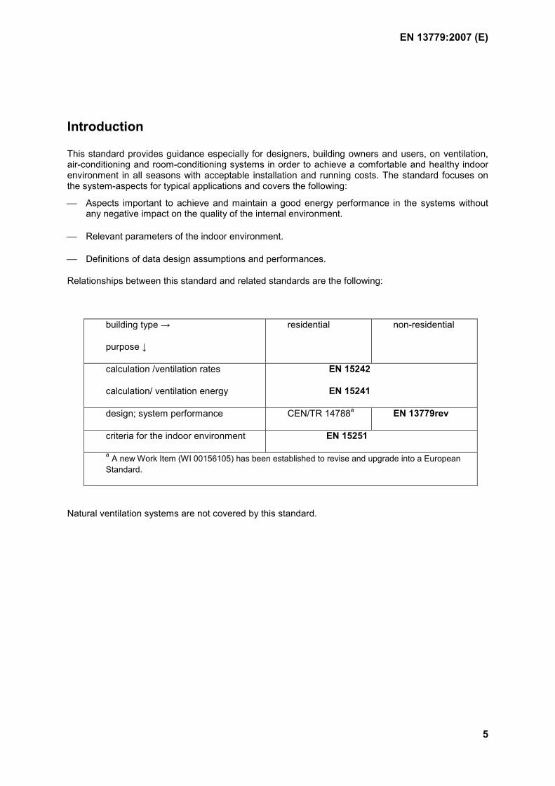
Relationships between this standard and related standards are the following:
building type →
purpose ↓
residential non-residential
calculation /ventilation rates
calculation/ ventilation energy
EN 15242
EN 15241
design; system performance CEN/TR 14788a EN 13779rev
criteria for the indoor environment EN 15251
a A new Work Item (WI 00156105) has been established to revise and upgrade into a European Standard.
Natural ventilation systems are not covered by this standard.
EN 13779:2007 (E)
6
1 Scope
This European Standard applies to the design and implementation of ventilation and room conditioning systems for non-residential buildings subject to human occupancy, excluding applications like industrial processes. It focuses on the definitions of the various parameters that are relevant for such systems.
The guidance for design given in this standard and its annexes are mainly applicable to mechanical supply and exhaust ventilation systems, and the mechanical part of hybrid ventilation systems.
Applications for residential ventilation are not dealt with in this standard. Performance of ventilation systems in residential buildings are dealt with in CEN/TR 14788.
The classification uses different categories. For some values, examples are given and, for requirements, typical ranges with default values are presented. The default values given in this standard are not normative as such, and should be used where no other values are specified. Classification should always be appropriate to the type of building and its intended use, and the basis of the classification should be explained if the examples given in the standard are not to be used.
NOTE Different standards may express the categories for the same parameters in a different way, and also the category symbols may be different.
2 Normative references
The following referenced documents are indispensable for the application of this document. For dated references, only the edition cited applies. For undated references, the latest edition of the referenced document (including any amendments) applies.
EN 308, Heat exchangers — Test procedures for establishing performance of air to air and flue gases heat recovery devices
EN 12097, Ventilation for Buildings — Ductwork — Requirements for ductwork components to facilitate maintenance of ductwork systems
EN 12599:2000, Ventilation for buildings — Test procedures and measuring methods for handing over installed ventilation and air conditioning systems
EN 12792:2003, Ventilation for buildings — Symbols, terminology and graphical symbols
EN 13053:2006, Ventilation for buildings — Air handling units — Rating and performance for units, components and sections
prEN 15232, Energy performance of buildings — Impact of Building Automation, Controls and Building Management
EN 15239, Ventilation for buildings — Energy performance of buildings — Guidelines for inspection of ventilation systems
EN 15240, Ventilation for buildings — Energy performance of buildings — Guidelines for inspection of air-conditioning systems
EN 15241, Ventilation for buildings — Calculation methods for energy losses due to ventilation and infiltration in commercial buildings
EN 15242, Ventilation for buildings — Calculation methods for the determination of air flow rates in buildings including infiltration
EN 13779:2007 (E)
7
EN 15251:2007, Indoor environmental input parameters for design and assessment of energy performance of buildings addressing indoor air quality, thermal environment, lighting and acoustics
EN ISO 7730, Ergonomics of the thermal environment — Analytical determination and interpretation of thermal comfort using calculation of the PMV and PPD indices and local thermal comfort criteria (ISO 7730:2005)
3 Terms and definitions
For the purposes of this document, the terms and definitions given in EN 12792:2003 and the following apply.
3.1 room conditioning system system able to keep comfort conditions in a room within a defined range
NOTE Air conditioning systems as well as surface based systems are included
3.2 types of air types of air are defined in 6.1
3.3 occupied zone usually the term “occupied zone” is used only for areas designed for human occupancy and is defined as a volume of air that is confined by specified horizontal and vertical planes
NOTE 1 The vertical planes are usually parallel with the walls of the room. Usually there is also a limit placed on the height of the occupied zone. Thus, the occupied zone in a room is that space in which the occupants are normally located and where the requirements for the indoor environment shall be satisfied. Definitions are given in 7.2.
NOTE 2 definition of the occupied zone is dependent on the geometry and the use of the room and should be specified case by case
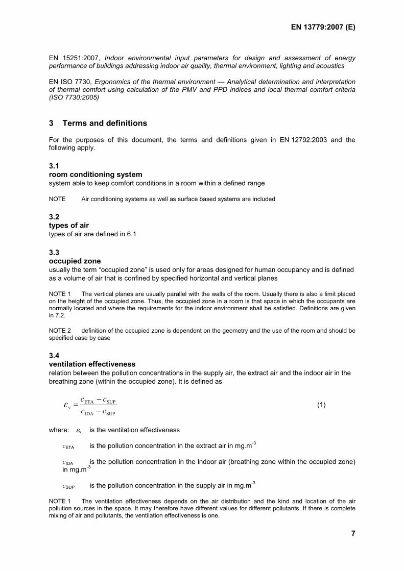
3.4 ventilation effectiveness relation between the pollution concentrations in the supply air, the extract air and the indoor air in the breathing zone (within the occupied zone). It is defined as
SUPIDA
SUPETAv cc
cc−−
=ε (1)
where: εv is the ventilation effectiveness
cETA is the pollution concentration in the extract air in mg.m-3
cIDA is the pollution concentration in the indoor air (breathing zone within the occupied zone) in mg.m-3
cSUP is the pollution concentration in the supply air in mg.m-3
NOTE 1 The ventilation effectiveness depends on the air distribution and the kind and location of the air pollution sources in the space. It may therefore have different values for different pollutants. If there is complete mixing of air and pollutants, the ventilation effectiveness is one.
EN 13779:2007 (E)
8
NOTE 2 Further information on ventilation effectiveness is given in Annex E and CR 1752.
NOTE 3 Another term frequently used for the same concept is “contaminant removal effectiveness”.
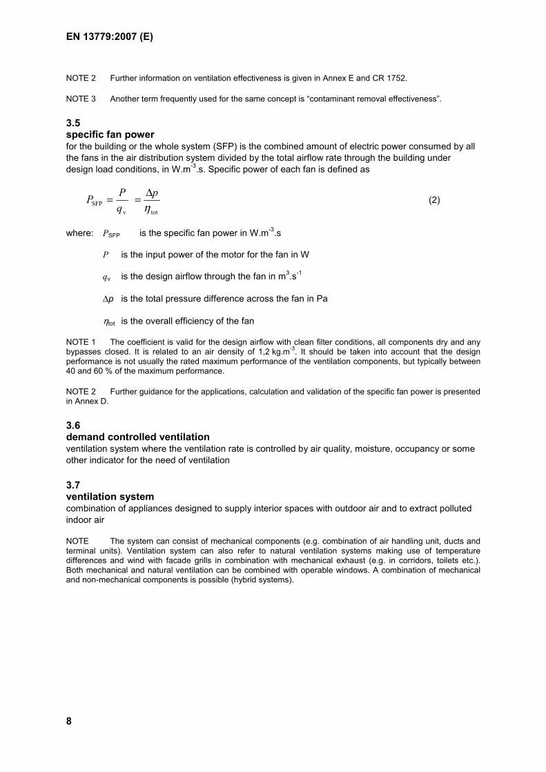
3.5 specific fan power for the building or the whole system (SFP) is the combined amount of electric power consumed by all the fans in the air distribution system divided by the total airflow rate through the building under design load conditions, in W.m-3.s. Specific power of each fan is defined as
totvSFP η
pqPP ∆== (2)
where: PSFP is the specific fan power in W.m-3.s
P is the input power of the motor for the fan in W
qv is the design airflow through the fan in m3.s-1
∆p is the total pressure difference across the fan in Pa
ηtot is the overall efficiency of the fan
NOTE 1 The coefficient is valid for the design airflow with clean filter conditions, all components dry and any bypasses closed. It is related to an air density of 1,2 kg.m-3. It should be taken into account that the design performance is not usually the rated maximum performance of the ventilation components, but typically between 40 and 60 % of the maximum performance.
NOTE 2 Further guidance for the applications, calculation and validation of the specific fan power is presented in Annex D.
3.6 demand controlled ventilation ventilation system where the ventilation rate is controlled by air quality, moisture, occupancy or some other indicator for the need of ventilation
3.7 ventilation system combination of appliances designed to supply interior spaces with outdoor air and to extract polluted indoor air
NOTE The system can consist of mechanical components (e.g. combination of air handling unit, ducts and terminal units). Ventilation system can also refer to natural ventilation systems making use of temperature differences and wind with facade grills in combination with mechanical exhaust (e.g. in corridors, toilets etc.). Both mechanical and natural ventilation can be combined with operable windows. A combination of mechanical and non-mechanical components is possible (hybrid systems).
EN 13779:2007 (E)
9
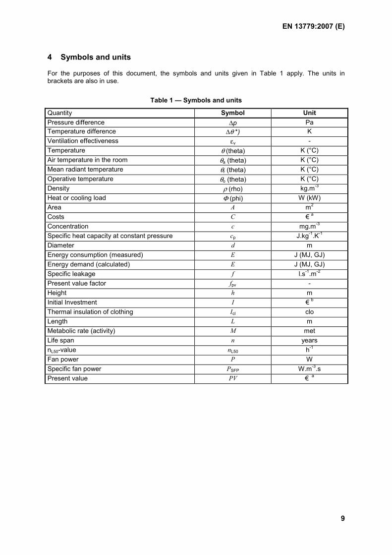
4 Symbols and units
For the purposes of this document, the symbols and units given in Table 1 apply. The units in brackets are also in use.
Table 1 — Symbols and units
Quantity Symbol Unit Pressure difference ∆p Pa Temperature difference ∆θ *) K Ventilation effectiveness εv - Temperature θ (theta) K (°C) Air temperature in the room θa (theta) K (°C) Mean radiant temperature θr (theta) K (°C) Operative temperature θo (theta) K (°C) Density ρ (rho) kg.m-3 Heat or cooling load Φ (phi) W (kW) Area A m2 Costs C € a Concentration c mg.m-3 Specific heat capacity at constant pressure cp J.kg-1.K-1 Diameter d m Energy consumption (measured) E J (MJ, GJ) Energy demand (calculated) E J (MJ, GJ) Specific leakage f l.s-1.m-2 Present value factor fpv - Height h m Initial Investment I € b Thermal insulation of clothing Icl clo Length L m Metabolic rate (activity) M met Life span n years nL50-value nL50 h-1 Fan power P W Specific fan power PSFP W.m-3.s Present value PV € a
EN 13779:2007 (E)
10
Table 1 — Symbols and units (continued)
Pressure p Pa Mass flow rate qm kg.s-1 Volume flow rate qv m3.s-1 (l.s-1, m3.h-1) Interest rate r - Time t s (h) Volume V m3 Air velocity v m.s-1 a Or National currency b EN 12792 prefers Θ but t and T may be used as well.
5 Agreement of design criteria
5.1 General
The design criteria specify the information needed to design the system. These criteria also constitute the basis for the measurements that will be carried out during the hand-over process. They provide the common language between all the parties including the client, designer, contractor and the operation and maintenance personnel.
Information necessary to design the system is organised on the basis of various documents outlined in 5.2 to 5.10. If the method used for dimensioning the system requires more details, they shall be provided.
Calculation procedure for the energy requirements of the ventilation system is presented in EN 15241.
5.2 Principles
Although in this standard the terms “client”, “designer” or “contractor” are used to describe the function, the responsibilities are dependent on the contract. Their use does not presuppose any definition of responsibility for the information. Nevertheless, if one party does not provide the information, the other shall ask for it or make and record the necessary assumptions. All key design decisions shall be agreed and documented.
The description of the characteristics of the environment and the structure of the building shall be obtained for design. The desired results required at the time of hand-over and during normal operation shall be specified and documented.
The description of the building with construction data, use and requirements is an evolving process with an increasing degree of detail and accuracy with the evolution of the project. Therefore the use of all specifications shall always be stated clearly. The details about the information needed are also dependent on the calculation method that is employed. The introduction of a system of abbreviations for constructions, room use and requirements to be used throughout the design phase is recommended.
5.3 General building characteristics
5.3.1 Location, outdoor conditions, neighbourhood
Information about the location of the relevant building, the significant neighbourhood characteristics such as adjacent buildings, shading, reflections, emissions, roads, airfields, sea coast, special requirements and all other information that will influence the building design shall be specified in design. The reference for noise and wind exposure of facades should be given, if available. The category of outdoor air shall be defined in accordance with Table 4.
EN 13779:2007 (E)
11
5.3.2 Climatic data outdoors
Information shall be given on climatic environment; as a minimum, design conditions for winter and summer are required. The most important climatic parameters for the design are:
Winter: outdoor temperature and wind speed;
Summer: outdoor temperature, humidity and solar radiation.
The reference year taken in order to estimate annual energy consumption shall be defined. Additional information about the occurrence of extreme situations is useful in some cases, especially to check the comfort situation. prEN 15243 provides more information about application.
5.3.3 Information on the operation of the building
The occupancy profile during typical days, annual periods of non-occupancy (e.g. schools etc.), and on general operational use (e.g. weekend, night etc.) shall be specified.
5.4 Construction data
All building parts shall be specified in a list with their relevant construction data.
5.5 Geometrical description
The geometrical description including information about the orientation of the elements exposed to the outdoors shall be presented, and this can be done in the form of drawings and/or tables. The specification of the net volume and floor area, room by room, is recommended.
5.6 Use of the rooms
5.6.1 General
The information about the use of each room, or group of rooms with similar use shall be given, preferably in a table. The necessary information according to A.1 of EN 12599:2000 shall also be included.
5.6.2 Human occupancy
The design condition in respect of the number of people that can be in the room for a longer period (see Table 12) shall be specified. This number constitutes a basic condition of use because the ventilation rate shall be designed for this level of occupancy. In addition the activity and clothing has to be defined.
The occupancy level shall be given as schedule, for example by specifying hourly values on typical days.
5.6.3 Other internal heat gains
Internal heat gains (persons, lighting and equipment) shall be specified for the various rooms or group of rooms. The gains shall be defined as follows:
sensible gains, convective or radiative
latent gains.
They shall be defined as schedules similar to occupation.
EN 13779:2007 (E)
12
NOTE A.17 gives further information on internal loads.
5.6.4 Other internal pollution and moisture sources
Special pollution or moisture production in a room shall be defined when relevant, with reference to the limits on these pollutants that may be encountered inside the room. Each pollutant shall be defined by its schedule of production and by the limit value to be admitted.
5.6.5 Given extract airflow
In some applications the extract airflow is given by the kind of process or equipment. In this case the extract airflow shall be defined.
5.7 Requirements in the rooms
5.7.1 General
The requirements (desired results according to 7.3 to 7.6) and internal loads (A.17) shall be specified room by room. The requirements with respect to thermal conditions and draught shall be satisfied in the occupied zone, specified in accordance with 7.2.
5.7.2 Type of control
The type of control of the indoor environment shall be specified according to the definitions given in Table 7, and it shall be adapted to the use of the room.
5.7.3 Thermal and moisture conditions
The thermal conditions in the room shall be specified in accordance with 7.3, the moisture conditions in accordance with 7.5 and EN 15251.
5.7.4 Air quality for people
The level of air quality required, and the method of classification applied shall be specified. Whether smoking is allowed or not is an important input. The necessary air flow rates to achieve the specified requirements shall be calculated. If nothing is declared, the rates of outdoor air per person for Indoor Air Quality category IDA 2 can be used as a default.
5.7.5 Air velocities
The air velocity in the occupied zone shall not exceed the agreed limits.
5.7.6 Noise level
With no regulations or specific requirements the reference values in A.16 are valid as maximum allowable sound pressure level from the system in the room.
5.7.7 Lighting
The lighting shall be designed for the actual requirements in the rooms. The installed electrical power for the lighting should not be too high for reasons of energy conservation, as the energy is not only required for lighting but also for cooling in summertime. Typical values for lighting levels and lighting power requirements are given in A.17.3.
EN 13779:2007 (E)
13
5.8 System requirements
The relevant system requirements shall be specified. The system requirements shall also conform to existing national regulations and guidelines, including those for structural fire safety and the regulations related to acoustics.
The system requirements typically include:
-location of air intake and discharge openings, see 6.2.3
-air filtering
-heat recovery
-re-use of extract air
-thermal insulation of the system
-airtightness of the system
-pressure conditions within the system and the building, taking into account the building and system airtightness
-power consumption
-space requirements for components and systems
-aspects to installation, operation and maintenance
NOTE Annex A gives further information and default values.
5.9 General requirements for control and monitoring
The method for the control and monitoring of all the systems shall be specified. In some applications it makes sense to distinguish between the first year(s) of operation and the time after.
The monitoring of the energy consumption shall allow a periodic check of the energy consumption of important individual systems and of the whole building. Therefore a measuring concept shall be identified at an early stage of the project and the necessary measuring devices installed. Changes of uses and requirements should be followed by adaptations of the system.
5.10 General requirements for maintenance and safety of operation
The system shall be designed to allow efficient service and maintenance to ensure effective operation.
NOTE 1 Further guidance is given in A.14.
The system shall be so designed that, with proper operation and maintenance, it will remain in ope-rating condition for a reasonable period of time. The system shall be designed so as to facilitate cleaning, maintenance and service operation (see EN 12097). The equipment shall be furnished with appropriate protection and safety devices for maintenance and repair work, and for emergency stopping.
NOTE 2 National authorities may give more detailed requirements or instructions for safety in operation and maintenance.
EN 13779:2007 (E)
14
5.11 Process from project initiation to operation
The process from the initiation of the project to the normal operation is generally characterised by the following steps. Nevertheless the definitive organisation is always in accordance with the specific contract.
NOTE 1 More details are given in Annex C in the form of checklists.
a) Project initiation.
b) Definition of design conditions and requirements.
c) Check with authorities, relevant regulations.
d) Design.
e) Installation.
f) Check of the installation.
g) Start of operation, check of functions, balancing, testing with written records.
h) Declaration of finished installation, addressed to the client.
i) Common completeness check, functional tests, functional measurements and special measure-ments according to EN 12599.
j) Hand over the system including the delivery of all relevant documents with instructions how to operate and maintain the system, to the client.
k) Operation and maintenance.
l) Regular inspections (see EN 15240 and EN 15239).
m) Monitoring the energy consumption by bookkeeping or another way of recording.
NOTE 2 Every ventilation, air-conditioning or room-conditioning system requires an adequate operation and maintenance procedure in order to satisfy the guaranteed conditions in the room, to ensure energy-efficient operation in all situations, to avoid emissions from the ventilation system to the room, to provide generally a good air quality in the rooms and to protect the system from damage and premature failure. It is recommended to prepare a duty-booklet for operation, service and maintenance, to contain a description of the control, service and maintenance measures including the time intervals and responsibilities (see also EN 15240 and EN 15239).
6 Classification
6.1 Specification of types of air
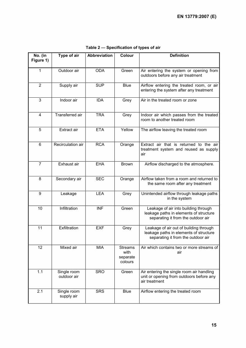
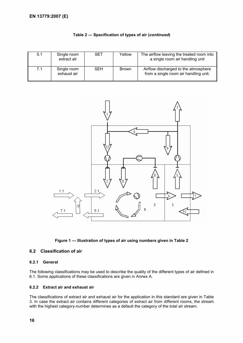
The types of air in a building and in a ventilation or air-conditioning system are specified in Table 2 and illustrated in Figure 1. The abbreviations and colours given in Table 2 shall be used to mark the type of air in drawings of ventilation or air-conditioning systems. The abbreviations can also be helpful for the labelling of system parts.
EN 13779:2007 (E)
15
Table 2 — Specification of types of air
No. (in Figure 1)
Type of air Abbreviation Colour Definition
1 Outdoor air
ODA
Green Air entering the system or opening from outdoors before any air treatment
2 Supply air
SUP
Blue Airflow entering the treated room, or air entering the system after any treatment
3 Indoor air
IDA
Grey Air in the treated room or zone
4 Transferred air
TRA
Grey Indoor air which passes from the treated room to another treated room
5 Extract air
ETA
Yellow The airflow leaving the treated room
6 Recirculation air
RCA
Orange Extract air that is returned to the air treatment system and reused as supply air
7 Exhaust air
EHA
Brown Airflow discharged to the atmosphere.
8 Secondary air
SEC
Orange Airflow taken from a room and returned to the same room after any treatment
9 Leakage
LEA
Grey Unintended airflow through leakage paths in the system
10 Infiltration
INF
Green Leakage of air into building through leakage paths in elements of structure
separating it from the outdoor air
11 Exfiltration
EXF
Grey Leakage of air out of building through leakage paths in elements of structure
separating it from the outdoor air
12 Mixed air
MIA
Streams with
separate colours
Air which contains two or more streams of air
1.1 Single room outdoor air
SRO Green Air entering the single room air handling unit or opening from outdoors before any air treatment
2.1 Single room supply air
SRS Blue Airflow entering the treated room
EN 13779:2007 (E)
16
Table 2 — Specification of types of air (continued)
5.1 Single room extract air
SET Yellow The airflow leaving the treated room into a single room air handling unit
7.1 Single room exhaust air
SEH Brown Airflow discharged to the atmosphere from a single room air handling unit.
Figure 1 — Illustration of types of air using numbers given in Table 2
6.2 Classification of air
6.2.1 General
The following classifications may be used to describe the quality of the different types of air defined in 6.1. Some applications of these classifications are given in Annex A.
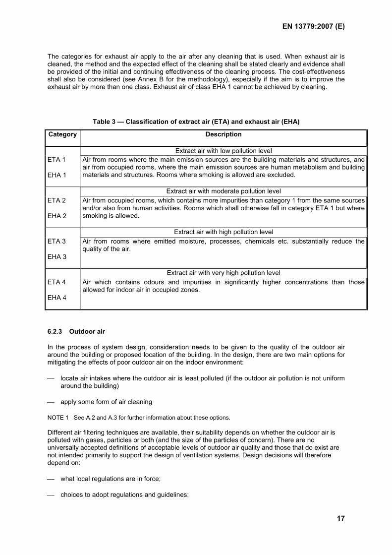
6.2.2 Extract air and exhaust air
The classifications of extract air and exhaust air for the application in this standard are given in Table 3. In case the extract air contains different categories of extract air from different rooms, the stream with the highest category-number determines as a default the category of the total air stream.
EN 13779:2007 (E)
17
The categories for exhaust air apply to the air after any cleaning that is used. When exhaust air is cleaned, the method and the expected effect of the cleaning shall be stated clearly and evidence shall be provided of the initial and continuing effectiveness of the cleaning process. The cost-effectiveness shall also be considered (see Annex B for the methodology), especially if the aim is to improve the exhaust air by more than one class. Exhaust air of class EHA 1 cannot be achieved by cleaning.
Table 3 — Classification of extract air (ETA) and exhaust air (EHA)
Category Description
Extract air with low pollution level ETA 1
EHA 1
Air from rooms where the main emission sources are the building materials and structures, and air from occupied rooms, where the main emission sources are human metabolism and building materials and structures. Rooms where smoking is allowed are excluded.
Extract air with moderate pollution level ETA 2
EHA 2
Air from occupied rooms, which contains more impurities than category 1 from the same sources and/or also from human activities. Rooms which shall otherwise fall in category ETA 1 but where smoking is allowed.
Extract air with high pollution level ETA 3
EHA 3
Air from rooms where emitted moisture, processes, chemicals etc. substantially reduce the quality of the air.
Extract air with very high pollution level ETA 4
EHA 4
Air which contains odours and impurities in significantly higher concentrations than those allowed for indoor air in occupied zones.
6.2.3 Outdoor air
In the process of system design, consideration needs to be given to the quality of the outdoor air around the building or proposed location of the building. In the design, there are two main options for mitigating the effects of poor outdoor air on the indoor environment:
locate air intakes where the outdoor air is least polluted (if the outdoor air pollution is not uniform around the building)
apply some form of air cleaning
NOTE 1 See A.2 and A.3 for further information about these options. Different air filtering techniques are available, their suitability depends on whether the outdoor air is polluted with gases, particles or both (and the size of the particles of concern). There are no universally accepted definitions of acceptable levels of outdoor air quality and those that do exist are not intended primarily to support the design of ventilation systems. Design decisions will therefore depend on:
what local regulations are in force;
choices to adopt regulations and guidelines;
EN 13779:2007 (E)
18
individual choices about the importance of specific pollutants that are not regulated (e.g. pollens, fungal spores of outdoor origin).
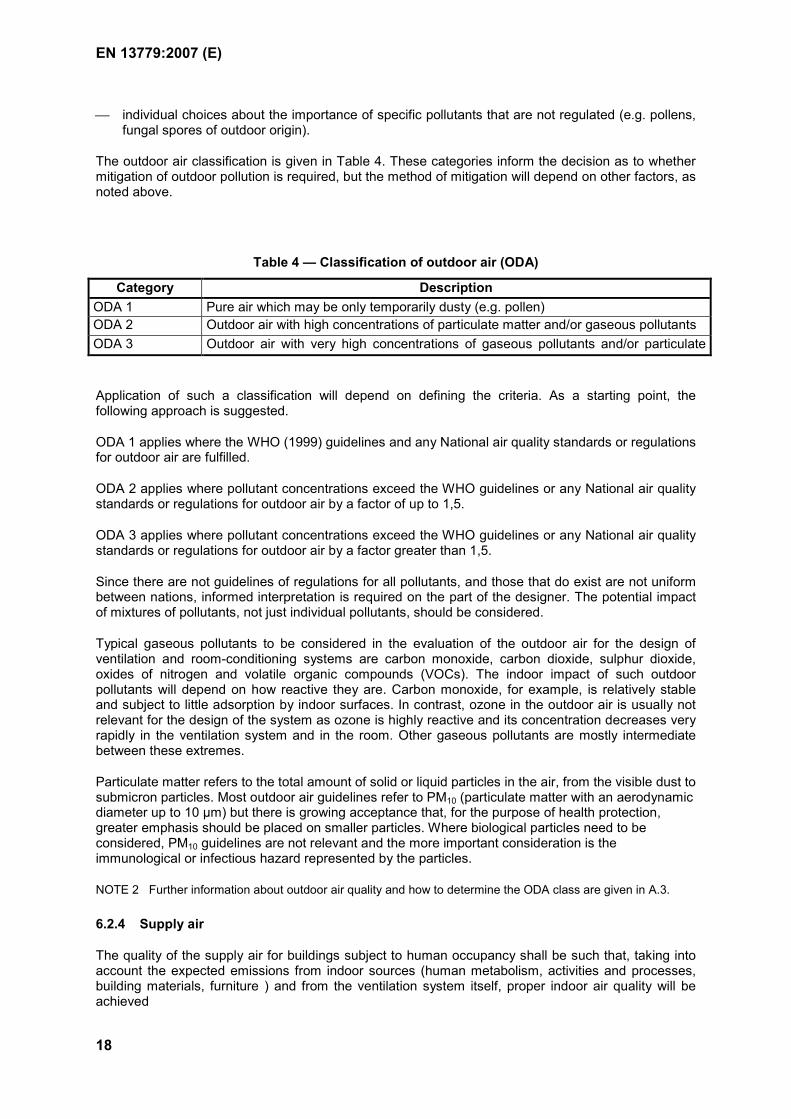
The outdoor air classification is given in Table 4. These categories inform the decision as to whether mitigation of outdoor pollution is required, but the method of mitigation will depend on other factors, as noted above.
Table 4 — Classification of outdoor air (ODA)
Category DescriptionODA 1 Pure air which may be only temporarily dusty (e.g. pollen) ODA 2 Outdoor air with high concentrations of particulate matter and/or gaseous pollutants ODA 3 Outdoor air with very high concentrations of gaseous pollutants and/or particulate
tt
Application of such a classification will depend on defining the criteria. As a starting point, the following approach is suggested.
ODA 1 applies where the WHO (1999) guidelines and any National air quality standards or regulations for outdoor air are fulfilled.
ODA 2 applies where pollutant concentrations exceed the WHO guidelines or any National air quality standards or regulations for outdoor air by a factor of up to 1,5.
ODA 3 applies where pollutant concentrations exceed the WHO guidelines or any National air quality standards or regulations for outdoor air by a factor greater than 1,5.
Since there are not guidelines of regulations for all pollutants, and those that do exist are not uniform between nations, informed interpretation is required on the part of the designer. The potential impact of mixtures of pollutants, not just individual pollutants, should be considered.
Typical gaseous pollutants to be considered in the evaluation of the outdoor air for the design of ventilation and room-conditioning systems are carbon monoxide, carbon dioxide, sulphur dioxide, oxides of nitrogen and volatile organic compounds (VOCs). The indoor impact of such outdoor pollutants will depend on how reactive they are. Carbon monoxide, for example, is relatively stable and subject to little adsorption by indoor surfaces. In contrast, ozone in the outdoor air is usually not relevant for the design of the system as ozone is highly reactive and its concentration decreases very rapidly in the ventilation system and in the room. Other gaseous pollutants are mostly intermediate between these extremes.
Particulate matter refers to the total amount of solid or liquid particles in the air, from the visible dust to submicron particles. Most outdoor air guidelines refer to PM10 (particulate matter with an aerodynamic diameter up to 10 µm) but there is growing acceptance that, for the purpose of health protection, greater emphasis should be placed on smaller particles. Where biological particles need to be considered, PM10 guidelines are not relevant and the more important consideration is the immunological or infectious hazard represented by the particles. NOTE 2 Further information about outdoor air quality and how to determine the ODA class are given in A.3.
6.2.4 Supply air
The quality of the supply air for buildings subject to human occupancy shall be such that, taking into account the expected emissions from indoor sources (human metabolism, activities and processes, building materials, furniture ) and from the ventilation system itself, proper indoor air quality will be achieved
EN 13779:2007 (E)
19
NOTE 1 Annex G of EN 15251:2007 gives more guidance on the use of "low polluting materials" or "low polluting buildings"
The outdoor air rates shall be specified in design of the system. If supply air also contains recirculation air, this shall be noted in design documentation, too. In order to avoid misunderstandings, it is recommended to define the quality of the supply air also by specifying the concentration limits that will apply to named pollutants (e.g. CO2, VOC) in the indoor air. Therefore a declaration of the expected emissions from indoor sources is also needed and, wherever possible, this should be related to concentration limits and emission standards.
NOTE 2 Extract air can be mixed to the supply air on purpose by recirculation or unintentionally by leakage. Special attention should be paid to the situation in heat recovery devices or sections, see A.4.
6.2.5 Indoor air
6.2.5.1 General
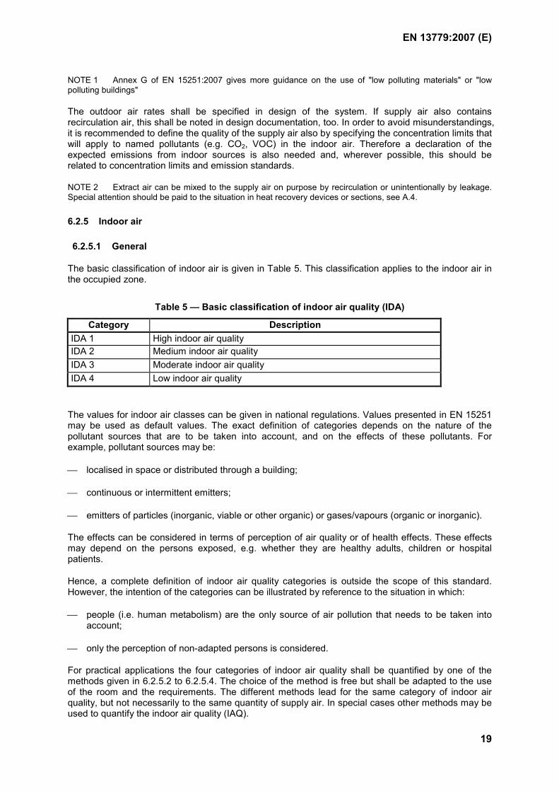
The basic classification of indoor air is given in Table 5. This classification applies to the indoor air in the occupied zone.
Table 5 — Basic classification of indoor air quality (IDA)
Category DescriptionIDA 1 High indoor air quality IDA 2 Medium indoor air quality IDA 3 Moderate indoor air quality IDA 4 Low indoor air quality
The values for indoor air classes can be given in national regulations. Values presented in EN 15251 may be used as default values. The exact definition of categories depends on the nature of the pollutant sources that are to be taken into account, and on the effects of these pollutants. For example, pollutant sources may be:
localised in space or distributed through a building;
continuous or intermittent emitters;
emitters of particles (inorganic, viable or other organic) or gases/vapours (organic or inorganic).
The effects can be considered in terms of perception of air quality or of health effects. These effects may depend on the persons exposed, e.g. whether they are healthy adults, children or hospital patients.
Hence, a complete definition of indoor air quality categories is outside the scope of this standard. However, the intention of the categories can be illustrated by reference to the situation in which:
people (i.e. human metabolism) are the only source of air pollution that needs to be taken into account;
only the perception of non-adapted persons is considered.
For practical applications the four categories of indoor air quality shall be quantified by one of the methods given in 6.2.5.2 to 6.2.5.4. The choice of the method is free but shall be adapted to the use of the room and the requirements. The different methods lead for the same category of indoor air quality, but not necessarily to the same quantity of supply air. In special cases other methods may be used to quantify the indoor air quality (IAQ).
EN 13779:2007 (E)
20
NOTE 1 Further guidance for determining the classification of IAQ is presented in EN 15251, taking also into account pollution sources other than occupant and smoking. The selection of non- or low-pollution materials for the building is strongly recommended, rather than increasing the rate of outdoor air in order to dilute avoidable emissions. This applies whatever approach is taken to defining air quality, and should include emissions from all indoor sources, e.g. furnishing, carpets and the ventilation or air-conditioning system itself.
Where emissions from materials can be estimated on a “per m2” basis, a total required ventilation rate can be calculated by combining the requirement per person and the requirements per m2. Where pollutants will be present but not immediately perceived, additional allowance should be made. Alternatively, the air cleaning required to achieve acceptable concentrations (or percentage removal) can be specified. This would be common, for example, in relation to hospitals. The methods would depend on the premises, the pollutants present and the national codes that apply.
All categories and figures are informative. Normative values and ways to calculate the total ventilation rate taking into account the different pollution sources can be given on national level. Annex A presents default values.
NOTE 2 For spaces for human occupancy, the ventilation option for periods of non-occupancy shall be specified according to national regulations so that the intended quality of indoor air is achieved at the start of occupancy. The main options for ventilation outside occupancy are:
-basic ventilation rate throughout the non-occupancy period, e.g. using extract from hygiene rooms -earlier start of ventilation before occupancy -run the ventilation system for short periods during the period of non-occupancy
A minimum value of 0,1 to 0,2 l/s,m2 is recommended if national requirements are not available.
NOTE 3 Further guidance for expressing the quality of indoor air, and how to specify the indoor environment in building design, is given in ISO/DIS 16814
6.2.5.2 Indirect classification by the rate of outdoor air per person
This method is a well-based practical method for all situations where the rooms serve for typical human occupancy. The outdoor air rates shall be specified according to national regulations and guidelines. The specified values shall be fulfilled in the occupied zone.
NOTE Values presented in Table A.10 may be used as default values.
6.2.5.3 Indirect classification by the air flow rate per floor area
This method can in some cases be used to design a system for rooms which are not for human occupancy and which do not have a clearly defined use (for example storage rooms).
NOTE Default values for these cases are given in Table A.11.
6.2.5.4 Classification by CO2-level
Indoor air quality can be categorised by CO2 concentration. CO2 is a good indicator for the emission of human bioeffluents. Classification by the CO2-level is well established for occupied rooms, where smoking is not allowed and pollution is caused mainly by human metabolism.
NOTE 1 Default values for indoor air quality categorised by CO2 concentration are given in Table A.10 and in
EN 15251:2007, Annex B.
NOTE 2 The CO2-based categories would be nominally equivalent to outdoor airflow rates for non-smoking spaces, for a certain activity level. The rates given for non-smoking areas take into consideration the human metabolism as well as typical emissions in low-pollution buildings. In cases with high activity levels (M > 1.2 met), the outdoor air rates should be increased according to EN ISO 7730. If the number of occupants per square metre is known, then the air quality can also be expressed as an airflow rate per square metre. This method can in some cases be used to design a system for rooms that are not for human occupancy and do not have a clearly defined use (for example storage rooms)
EN 13779:2007 (E)
21
6.2.5.5 Classification by concentration levels for specific pollutants
This method of classification is suitable for situations with significant emissions of specific pollutants. If there is sufficient information about all the indoor emissions, then ventilation rate requirements can be calculated as shown in 7.4.2.3. Where the emission rates are not known, the required air quality can also be indirectly specified by the ventilation rate based on experience.
6.3 System tasks and basic system types
Ventilation, air-conditioning and room-conditioning systems are intended to control the indoor air quality and the thermal and humidity conditions in the room to a specification that is agreed in ad-vance. The specification of the indoor environment also has consequences for the price of the installation, the space requirements for the system and the running costs. Therefore a solution shall be found which is well suited to the actual requirements.
Ventilation systems consist of a supply and an extract air system and usually they are equipped with filters for the outdoor air, heaters and heat recovery devices. Extract air systems with no supply air system cannot fulfil all the given requirements. Supply air systems with no extract air system do not generally allow heat recovery and lead to an overpressure which may be in some cases hazardous to the building fabric.
The basic categories of the system type are dependant on its capability for controlling the indoor air quality and the means and degree of control of the thermodynamic properties in the room. The category and type of control, and parameters to be controlled shall be specified.
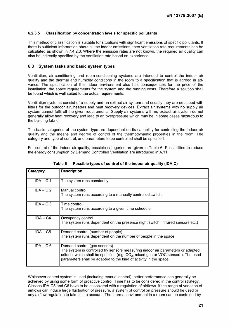
For control of the indoor air quality, possible categories are given in Table 6. Possibilities to reduce the energy consumption by Demand Controlled Ventilation are introduced in A.11.
Table 6 — Possible types of control of the indoor air quality (IDA-C)
Category Description
IDA – C 1 The system runs constantly.
IDA – C 2 Manual control The system runs according to a manually controlled switch.
IDA – C 3 Time control The system runs according to a given time schedule.
IDA – C4 Occupancy control The system runs dependent on the presence (light switch, infrared sensors etc.)
IDA – C5 Demand control (number of people) The system runs dependent on the number of people in the space.
IDA – C 6 Demand control (gas sensors) The system is controlled by sensors measuring indoor air parameters or adapted criteria, which shall be specified (e.g. CO2, mixed gas or VOC sensors). The used parameters shall be adapted to the kind of activity in the space.
Whichever control system is used (including manual control), better performance can generally be achieved by using some form of proactive control. Time has to be considered in the control strategy. Classes IDA-C5 and C6 have to be associated with a regulation of airflows. If the range of variation of airflows can induce large fluctuation of pressure, a system of control on pressure should be used or any airflow regulation to take it into account. The thermal environment in a room can be controlled by
EN 13779:2007 (E)
22
the ventilation system alone or in combination with other means such as cooled/heated ceilings, floors etc. Based on this, the two basic system types given in Table 7 are used. More information about system types is given in prEN 15243:2005, Clause 14.
Table 7 — Basic system types according to the means of controlling the thermal environment in a room
Description Name of the system typeControlled by the ventilation system alone All air system Controlled by the ventilation system in combination with other means (e.g. heating appliances, surface heating or cooling, radiators).
Mixed system
Possible treatments of the air to change the hygrothermal environment are: heating, cooling, humidification and dehumidification. For the purpose of classification, a function is valid only where the system is able to control this function in such a way that the given boundary conditions in the room can be met. This means, for instance, that uncontrolled dehumidification in a cooling unit is not counted as dehumidification in the above-mentioned way.
The system functions shall be specified, providing a list of functions as relevant
-ventilation
-heating
-cooling
-humidification
-dehumidification.
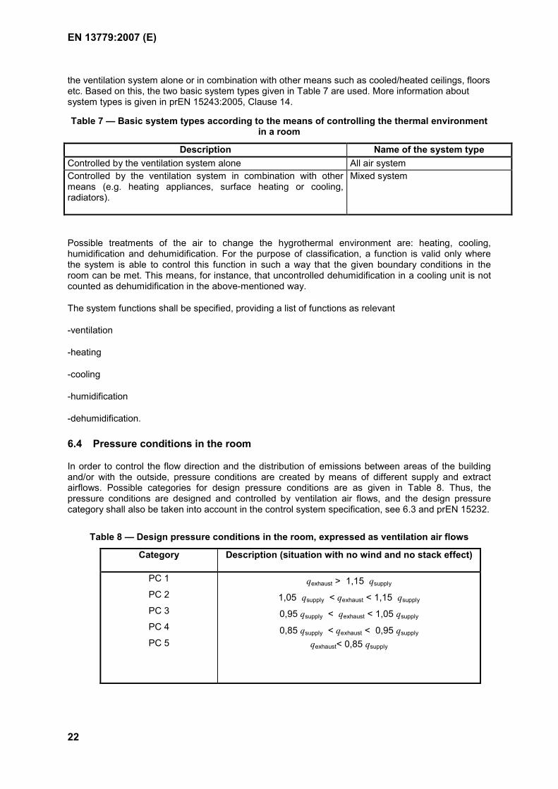
6.4 Pressure conditions in the room
In order to control the flow direction and the distribution of emissions between areas of the building and/or with the outside, pressure conditions are created by means of different supply and extract airflows. Possible categories for design pressure conditions are as given in Table 8. Thus, the pressure conditions are designed and controlled by ventilation air flows, and the design pressure category shall also be taken into account in the control system specification, see 6.3 and prEN 15232.
Table 8 — Design pressure conditions in the room, expressed as ventilation air flows
Category Description (situation with no wind and no stack effect)
PC 1
PC 2
PC 3
PC 4
PC 5
qexhaust > 1,15 qsupply
1,05 qsupply < qexhaust < 1,15 qsupply
0,95 qsupply < qexhaust < 1,05 qsupply
0,85 qsupply < qexhaust < 0,95 qsupply
qexhaust< 0,85 qsupply
EN 13779:2007 (E)
23
The choice of pressure level depends on the specific application. In some cases more than one level of under- or overpressure is required to control the airflow between all areas of the building. When the required pressure levels are to be achieved with a wind, the building envelope shall be airtight. In addition to flow direction requirements, also other aspects may have to be taken into account.
NOTE For example in cold climates certain wall structures require negative pressure indoors to avoid moisture damages to the construction, and in warm humid climates positive pressure indoors is desired from the structures point of view.
When nothing is declared, category PC 3 shall be adopted.
6.5 Specific fan power
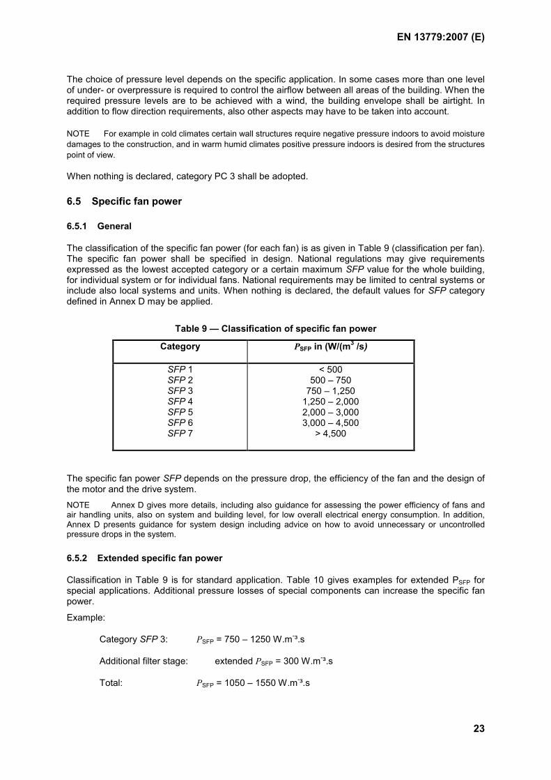
6.5.1 General
The classification of the specific fan power (for each fan) is as given in Table 9 (classification per fan). The specific fan power shall be specified in design. National regulations may give requirements expressed as the lowest accepted category or a certain maximum SFP value for the whole building, for individual system or for individual fans. National requirements may be limited to central systems or include also local systems and units. When nothing is declared, the default values for SFP category defined in Annex D may be applied.
Table 9 — Classification of specific fan power
Category PSFP in (W/(m3 /s)
SFP 1 SFP 2 SFP 3 SFP 4 SFP 5 SFP 6 SFP 7
< 500 500 – 750
750 – 1,250 1,250 – 2,000 2,000 – 3,000 3,000 – 4,500
> 4,500
The specific fan power SFP depends on the pressure drop, the efficiency of the fan and the design of the motor and the drive system.
NOTE Annex D gives more details, including also guidance for assessing the power efficiency of fans and air handling units, also on system and building level, for low overall electrical energy consumption. In addition, Annex D presents guidance for system design including advice on how to avoid unnecessary or uncontrolled pressure drops in the system.
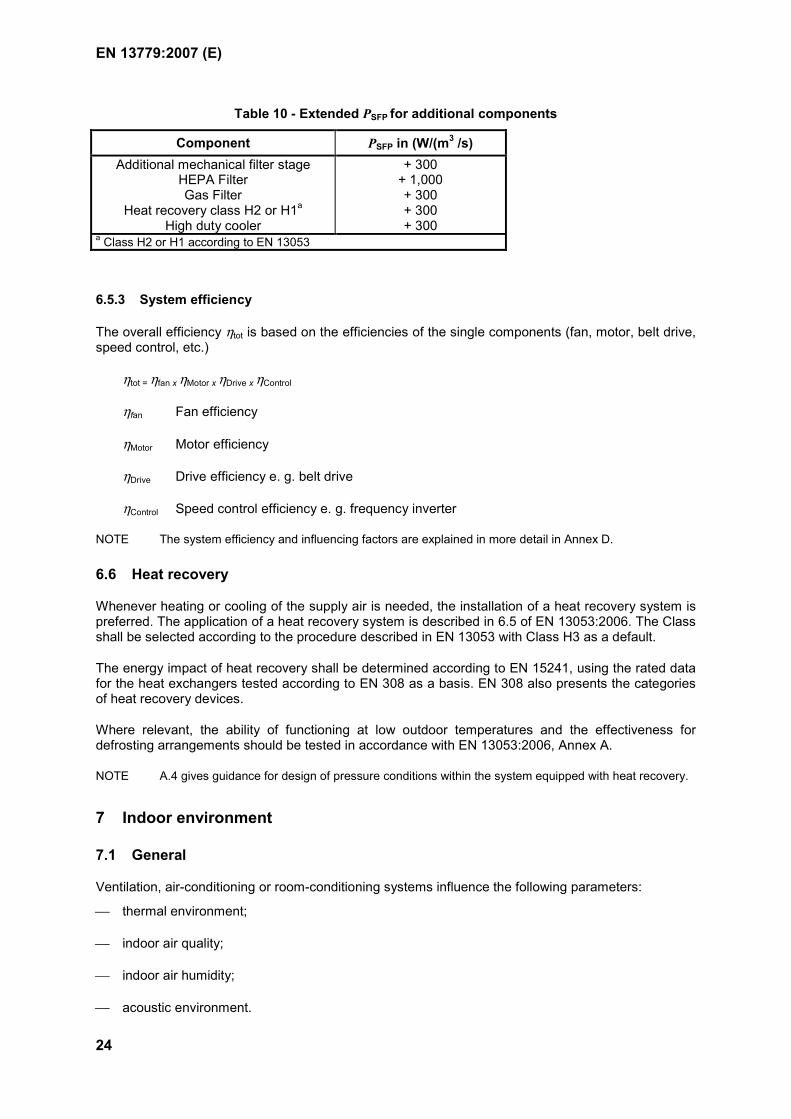
6.5.2 Extended specific fan power
Classification in Table 9 is for standard application. Table 10 gives examples for extended PSFP for special applications. Additional pressure losses of special components can increase the specific fan power.
Example:
Category SFP 3: PSFP = 750 – 1250 W.m-³.s
Additional filter stage: extended PSFP = 300 W.m-³.s
Total: PSFP = 1050 – 1550 W.m-³.s
EN 13779:2007 (E)
24
Table 10 - Extended PSFP for additional components
Component PSFP in (W/(m3 /s) Additional mechanical filter stage
HEPA Filter Gas Filter
Heat recovery class H2 or H1a High duty cooler
+ 300 + 1,000 + 300 + 300 + 300
a Class H2 or H1 according to EN 13053
6.5.3 System efficiency
The overall efficiency ηtot is based on the efficiencies of the single components (fan, motor, belt drive, speed control, etc.)
ηtot = ηfan x ηMotor x ηDrive x ηControl
ηfan Fan efficiency
ηMotor Motor efficiency
ηDrive Drive efficiency e. g. belt drive
ηControl Speed control efficiency e. g. frequency inverter
NOTE The system efficiency and influencing factors are explained in more detail in Annex D.
6.6 Heat recovery
Whenever heating or cooling of the supply air is needed, the installation of a heat recovery system is preferred. The application of a heat recovery system is described in 6.5 of EN 13053:2006. The Class shall be selected according to the procedure described in EN 13053 with Class H3 as a default.
The energy impact of heat recovery shall be determined according to EN 15241, using the rated data for the heat exchangers tested according to EN 308 as a basis. EN 308 also presents the categories of heat recovery devices.
Where relevant, the ability of functioning at low outdoor temperatures and the effectiveness for defrosting arrangements should be tested in accordance with EN 13053:2006, Annex A.
NOTE A.4 gives guidance for design of pressure conditions within the system equipped with heat recovery.
7 Indoor environment
7.1 General
Ventilation, air-conditioning or room-conditioning systems influence the following parameters:
thermal environment;
indoor air quality;
indoor air humidity;
acoustic environment.
EN 13779:2007 (E)
25
NOTE The comfort and the performance of persons in a room is also dependent on other influences such as: type of work and configuration of working place, lighting and colours, size of room, furniture, view to the outside, working conditions and working relationships and individual factors.
The design assumptions for the indoor environment are based on design agreements. Typical design assumptions are given in 7.3 to 7.6, more basic information including categories and default values about the design criteria in EN 15251 and further guidance on air quality is given in 7.4. The agreed requirements for the thermal environment, indoor air quality, indoor air humidity and the acoustic environment shall be met in the occupied zone as defined in 7.2. A system shall be designed for the specific needs of the project.
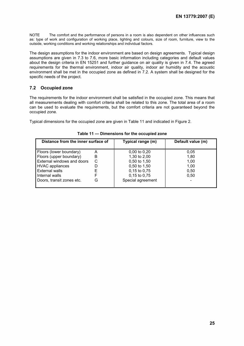
7.2 Occupied zone
The requirements for the indoor environment shall be satisfied in the occupied zone. This means that all measurements dealing with comfort criteria shall be related to this zone. The total area of a room can be used to evaluate the requirements, but the comfort criteria are not guaranteed beyond the occupied zone.
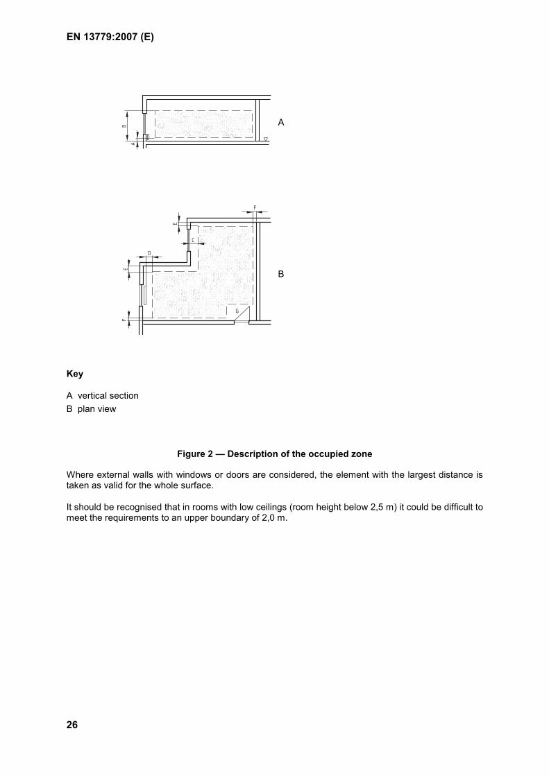
Typical dimensions for the occupied zone are given in Table 11 and indicated in Figure 2.
Table 11 — Dimensions for the occupied zone
Distance from the inner surface of Typical range (m) Default value (m)
Floors (lower boundary) A Floors (upper boundary) B External windows and doors C HVAC appliances D External walls E Internal walls F Doors, transit zones etc. G
0,00 to 0,20 1,30 to 2,00 0,50 to 1,50 0,50 to 1,50 0,15 to 0,75 0,15 to 0,75
Special agreement
0,05 1,80 1,00 1,00 0,50 0,50
-
EN 13779:2007 (E)
26
A
B
C
F
E
D
EF
G
A
B
Key
A vertical section B plan view
Figure 2 — Description of the occupied zone
Where external walls with windows or doors are considered, the element with the largest distance is taken as valid for the whole surface.
It should be recognised that in rooms with low ceilings (room height below 2,5 m) it could be difficult to meet the requirements to an upper boundary of 2,0 m.
EN 13779:2007 (E)
27
Special agreements should also be considered for the following types of zone, in which it could be difficult to meet the requirements to the thermal environment, especially with respect to draught and temperature:
a) transit zones;
b) zones close to doors that are often used or open;
c) zones close to supply air terminals;
d) zones close to units with high heat production or airflow rate.
Except when indicated or agreed otherwise, zones a) and b) are not considered part of the occupied zone, but zones c) and d) are considered part of the occupied zone.
If the use of a room is not based on the room dimensions but on other factors, the occupied zone can be defined according to the arrangement of working areas and equipment therein or by the location of the breathing zone.
7.3 Thermal environment
7.3.1 General
On the basis of agreed design values, a proportion of time that the design values may be exceeded (e.g. hours per day or days per year) may be specified.
7.3.2 Design assumptions
The most important design assumptions with respect to the thermal environment are the clothing and the activity of the occupants. Thermal comfort with given clothing and activity is therefore mainly due to the operative temperature and the air velocity. Further influences such as the vertical air temperature gradient, warm and cold floors and radiant asymmetry should be considered.
Design assumptions for clothing and activity for office buildings or similar working places for sedentary activities are given in EN 15251.
7.3.3 Air temperature and operative temperature
NOTE 1 In most cases the average room air temperature can be used as the design temperature, but especially if temperatures of large room surfaces differ significantly from the air temperature the operative temperature should be used.
In most of the applications in the scope of this standard there are low velocities (< 0,2 m.s-1) and small differences between the air temperature and the mean radiant temperature in the room (< 4°C). Therefore in this standard the operative temperature at a given location in the room is defined as
a ro 2
θ θθ
+= (3)
where θ0 is the operative temperature at the considered location in the room
θa is the air temperature in the room
θr is the mean radiant temperature of all surfaces (walls, floor, ceiling, windows, radiators etc.) with respect to the considered location in the room.
NOTE 2 Further information about the operative temperature is given in EN ISO 7726 and EN ISO 7730.
EN 13779:2007 (E)
28
Design values for the operative temperature in office buildings are given in EN 15251.
Except where agreed otherwise, the specified operative temperature shall apply to a location in the centre of the room at a height of 0,6 m above the floor.
7.3.4 Air velocities and draught rate
Design values for the air velocities shall be specified. The air velocity can be expressed as acceptable mean air velocity or as a draught rate (percentage of people dissatisfied due to draught) or draught curve, according to national regulations. Default design values for the local air velocity are given in EN ISO 7730.
The specified values shall be fulfilled in the occupied zone in all situations with normal operation. This requires that the system with its terminal devices be designed accordingly.
7.4 Indoor air quality
7.4.1 Design assumptions
The most important design assumptions with respect to the indoor air quality are information about the human occupancy, whether smoking is allowed or not, and emissions from sources other than human metabolism and smoking. It should also be taken into account that air quality is likely to be perceived more negatively as temperature and humidity increase.
Typical values for human occupancy are given in Table 12. The design shall be based whenever possible on the real data for the project. However, if no values are declared, the default values given in Table 12 shall be applied. If no information in respect of smoking is declared, it shall be assumed that, in all kinds of use given in Table 12, smoking is not allowed.
NOTE National smoking regulations may give further requirements and guidance for ventilation in buildings with both smoking and non-smoking areas.
Table 12 — Design assumptions for floor area per person
Floor area per person in m2.person-1 a Kind of use Default value
Landscaped office room Small office room Meeting room Department store Classroom Hospital ward Hotel bedroom Restaurant
12 10 3,0 4,0 2,5 10 10 1,5
a Net floor-area per room.
Emissions from sources other than human metabolism and smoking shall be specified as clearly as possible. If no further emissions are taken into consideration, this shall be noted in design documentation.
EN 13779:2007 (E)
29
7.4.2 Supply airflow rates
7.4.2.1 General
The outdoor air rate shall be determined using the following criteria:
human occupancy with or without smoking
other known emissions
heating or cooling load that shall be dissipated by ventilation.
In order to prevent uncontrolled loss of supply air, the ductwork shall be airtight enough. Methods to estimate the impact of air leakages in ducts and air handling units are described in EN 15242, see also A.8.
Recommended design ventilation rates are given in EN 15251:2007, Annex B.
7.4.2.2 Human occupancy
The ventilation rate for human occupancy shall be determined using the information in 6.2.5 or by using specific values for the airflow rate based on regulations.
7.4.2.3 Other known emissions
The ventilation rate needed for the emission rate and the allowed concentration level in the room give the dilution of a known emission, as follows:
SUPIDA
Em,SUPv, cc
−= (4)
where: qv,SUP is the volume flow rate of supply air in m3.s-1
qm,E is the mass flow rate of emission in the room in mg.s-1
cIDA is the allowed concentration in the room in mg.m-3
cSUP is the concentration in the supply air in mg.m-3
In case of different pollutants, it is necessary to check all relevant pollutants in order to determine the most critical one. As a rule, source control is preferable to ventilation.
Equation (4), given above, is valid for a steady-state situation (default situation) with a long lasting constant emission. When the emission-period is short, the stationary equilibrium-concentration may not be achieved or the airflow can be reduced for a given maximum concentration level. The time-dependence of the concentration level in the room is given by the following (supply air rate = extract air rate):
−+=−
⋅− tV
q
I eqq
cctc r
SUPv,
1)0()(SUPv,
Em,IDASUPDA (5)
where cIDA (t) is the concentration in the room at time t in mg.m-3
cSUP is the concentration in the supply air in mg.m-3
EN 13779:2007 (E)
30
cIDA (0) is the concentration in the room at the beginning (t = 0) in mg.m-3
qv,SUP is the volume flow rate of supply air in m3.s-1
qm,E is the mass flow rate of emission in the room in mg.s-1
Vr is the volume of air in the room in m3
t is the time in s
7.4.2.4 Heating and cooling load
The minimum ventilation rate can be determined by the requirements for the heating and cooling load. If for this reason the ventilation rate becomes much higher than that for human occupancy, an alternative solution for the dissipation of the heat could be more energy-efficient.
The required ventilation rate for heating or cooling is calculated from the following:
v,SUPp a,IDA SUP
qcρ θ θ
Φ=× −
(6)
where: qV,SUP is the volume flow rate of supply air in m3.s-1
Φ is the thermal load in W
ρ is the density of air in kg.m-3
cp is the thermal capacity of air in J.kg-1.K-1
θa,IDA is the temperature of the room air in °C
θSUP is the temperature of the supply air in °C
The density and the thermal capacity of air are dependent on its temperature and pressure. The calculation shall be made with the values applicable to the real situation.
7.4.3 Extract airflow rates
In a balanced mechanical ventilation system with supply and extract air the extract airflow rate is given by the supply airflow rate and the pressure conditions needed.
For extract air systems the extract airflow rates shall be calculated according to the principles given in 7.4.2.2 to 7.4.2.4.
Extract air rates from kitchens and hygiene rooms shall be specified. National regulations can give minimum extract air flows for kitchens, toilets, washrooms etc. Typical and default design values for kitchen and toilets/washrooms are given in A.2. The extract air can be replaced by outside air or by transferred air from other rooms (see Table A.2).
7.5 Indoor air humidity
In the absence of alternative information, the design shall be based on the assumption that no humidity sources other than human occupancy and supply and infiltration air exist. In design, the following design criteria shall be considered, taking into account the energy issues, climatic conditions winter/summer, condensation risks, and options how to control the indoor air humidity:
EN 13779:2007 (E)
31
-absolute humidity, minimum value winter, and/or maximum value summer. (for example, 6 g/kg can be specified as a winter minimum, corresponding 22 C/ 40 %; while 12 g/kg can be specified as a summer maximum, corresponding 26 C/ 60 %)
-relative humidity, need to define minimum and/or maximum values
-risks for condensation and moisture damages in structures and systems (consideration of surface temperatures and/or pressure conditions)
-control of the indoor air humidity (see 6.3; example: uncontrolled dehumidification by cooling vs. controlled dehumidification)
NOTE 1 Humidification or dehumidification of room air is usually not required but if they are used the use should be limited to minimum and excess humidification and dehumidification avoided.
NOTE 2 EN 15251 gives more guidance on target values for humidification and dehumidification.
7.6 Acoustic environment
The system shall be designed to fulfil the requirements and specified maximum target levels for sound pressure in the room. The design shall take into account all sources of noise, including adjacent rooms, and sound reduction throughout the system. National regulations and standards give maximum permissible sound level, and can also give stricter target values in a form of classification.
NOTE Design A-weighted sound pressure levels generated and/or transmitted by the ventilation or air-conditioning system and other installations in different types of spaces are defined in Annex A. These values are mean values and valid with no noise sources from the outside or by the use of the room. The values include furniture but not people in the room. EN 15251 gives further information about noise criteria.
EN 13779:2007 (E)
32
Annex A (informative)
Guidelines for Good Practice
A.1 Field of application
The following guidelines are established for mechanical ventilation, air-conditioning and room-conditioning systems for buildings subject to human occupancy. When applying the given principles for other applications like natural or hybrid ventilation systems, their special needs should be considered in an appropriate way.
A.2 Intake and exhaust openings
A.2.1 General
With respect to pressure loss and energy demand, the duct system should be as short as possible.
However, at the same time the following requirements should be fulfilled.
The intake opening for outdoor air should be arranged in such a way that the outdoor air entering the system is, as far much as possible: clean, dry (free from rain etc), and cool in summertime.
The exhaust air should be discharged to the outdoors so as to minimise health hazards or harmful effects caused to the building, its occupants or the environment.
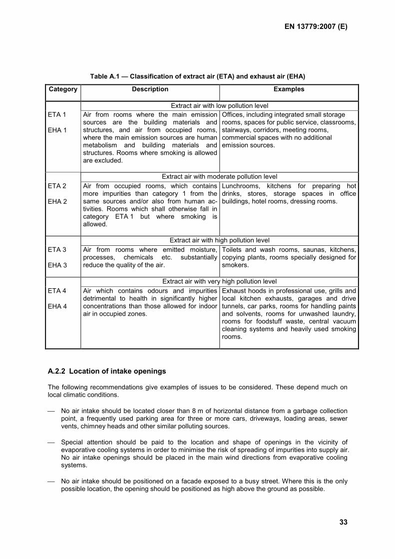
The arrangements depend much on the quality of exhaust air. In this, the exhaust and extract air classification should be applied. Table A.1, based on the classification described in 6.2.2, gives examples of room types for different categories. National regulations may give different requirements, for example in case smoking is allowed.
EN 13779:2007 (E)
33
Table A.1 — Classification of extract air (ETA) and exhaust air (EHA)
Category Description Examples
Extract air with low pollution level ETA 1
EHA 1
Air from rooms where the main emission sources are the building materials and structures, and air from occupied rooms, where the main emission sources are human metabolism and building materials and structures. Rooms where smoking is allowed are excluded.
Offices, including integrated small storage rooms, spaces for public service, classrooms, stairways, corridors, meeting rooms, commercial spaces with no additional emission sources.
Extract air with moderate pollution level ETA 2
EHA 2
Air from occupied rooms, which contains more impurities than category 1 from the same sources and/or also from human ac-tivities. Rooms which shall otherwise fall in category ETA 1 but where smoking is allowed.
Lunchrooms, kitchens for preparing hot drinks, stores, storage spaces in office buildings, hotel rooms, dressing rooms.
Extract air with high pollution level ETA 3
EHA 3
Air from rooms where emitted moisture, processes, chemicals etc. substantially reduce the quality of the air.
Toilets and wash rooms, saunas, kitchens, copying plants, rooms specially designed for smokers.
Extract air with very high pollution level ETA 4
EHA 4
Air which contains odours and impurities detrimental to health in significantly higher concentrations than those allowed for indoor air in occupied zones.
Exhaust hoods in professional use, grills and local kitchen exhausts, garages and drive tunnels, car parks, rooms for handling paints and solvents, rooms for unwashed laundry, rooms for foodstuff waste, central vacuum cleaning systems and heavily used smoking rooms.
A.2.2 Location of intake openings
The following recommendations give examples of issues to be considered. These depend much on local climatic conditions.
No air intake should be located closer than 8 m of horizontal distance from a garbage collection point, a frequently used parking area for three or more cars, driveways, loading areas, sewer vents, chimney heads and other similar polluting sources.
Special attention should be paid to the location and shape of openings in the vicinity of evaporative cooling systems in order to minimise the risk of spreading of impurities into supply air. No air intake openings should be placed in the main wind directions from evaporative cooling systems.
No air intake should be positioned on a facade exposed to a busy street. Where this is the only possible location, the opening should be positioned as high above the ground as possible.
EN 13779:2007 (E)
34
No air intake should be positioned where a back-flow of exhaust air or a disturbance from other pollutants or smelling emissions is expected (see also A.2.4).
No air intake should be positioned just above the ground. For example, a distance at least 1,5 times the maximum expected thickness of snow between the bottom of the intake and the ground is recommended.
On top of the building or when the concentrations on both sides of the building are similar, the intake should be arranged on the windward side of the building.
The air intake opening adjacent to unshaded places, roofs or walls should be arranged or protected so that the air will not be excessively heated by the sun in summer.
Wherever the risk of penetration of water in any form (snow, rain, mist, etc.) or dust (including leafs) into the system is apparent, an unprotected opening should be dimensioned for a maximum air velocity in the opening of 2 m.s-1 (see also EN 13030).
The height of the bottom of an air intake opening over a roof or deck should be at least 1,5 times the maximum yearly expected thickness of snow. The distance can be lower if the formation of a layer of snow is precluded by means of, for example, a snow shield.
Consideration should be given to the possibility for cleaning.
A.2.3 Location of exhaust openings
Discharge of exhaust air of category EHA 1 and EHA 2 to the outdoors through a discharge opening on the building wall is acceptable provided that:
distance of the discharge opening is at least 8 m from an adjacent building;
distance of the discharge opening is at least 2 m from an intake opening in the same wall (if possible, the intake opening should be below the discharge opening) - see also A.2.4;
discharge airflow rate is not more than 0,5 m3.s-1;
air velocity in the discharge opening is at least 5 m.s-1.
In all other cases the discharge should be placed on top of the roof. As a rule, the exhaust air is conducted above the roof of the highest section of the building and discharged upwards. The height of the bottom of a discharge opening over a roof or deck should be at least 1,5 times the maximum yearly expected thickness of snow. The distance can be lower if the formation of a layer of snow is precluded by means of, for example, a snow shield. Ecological or hygienic considerations can lead to greater heights and/or requirements in relation to the exit velocity.
A.2.4 Distance between intake and exhaust openings
Minimum recommended distances between intake and exhaust openings are given in Table A.2 and Figure A.1. .
EN 13779:2007 (E)
35
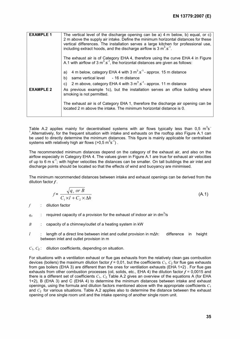
EXAMPLE 1 The vertical level of the discharge opening can be a) 4 m below, b) equal, or c) 2 m above the supply air intake. Define the minimum horizontal distances for these vertical differences. The installation serves a large kitchen for professional use, including extract hoods, and the discharge airflow is 3 m3.s-1.
The exhaust air is of Category EHA 4, therefore using the curve EHA 4 in Figure A.1 with airflow of 3 m3.s-1, the horizontal distances are given as follows:
a) 4 m below, category EHA 4 with 3 m3.s-1 - approx. 15 m distance b) same vertical level - 16 m distance c) 2 m above, category EHA 4 with 3 m3.s-1 - approx. 11 m distance EXAMPLE 2 As previous example 1c), but the installation serves an office building where
smoking is not permitted.
The exhaust air is of Category EHA 1, therefore the discharge air opening can be located 2 m above the intake. The minimum horizontal distance is 0.
Table A.2 applies mainly for decentralised systems with air flows typically less than 0,5 m3s.-
1.Alternatively, for the frequent situation with intake and exhausts on the rooftop also Figure A.1 can be used to directly determine the minimum distances. This figure is mainly applicable for centralised systems with relatively high air flows (>0,5 m3s-1) .
The recommended minimum distances depend on the category of the exhaust air, and also on the airflow especially in Category EHA 4. The values given in Figure A.1 are true for exhaust air velocities of up to 6 m s-1; with higher velocities the distances can be smaller. On tall buildings the air inlet and discharge points should be located so that the effects of wind and buoyancy are minimised.
The minimum recommended distances between intake and exhaust openings can be derived from the dilution factor f .
f = hClC
Borqv
∆×+× 21
(A.1)
f : dilution factor
qv : required capacity of a provision for the exhaust of indoor air in dm3/s
B : capacity of a chimney/outlet of a heating system in kW
l : length of a direct line between inlet and outlet provision in m∆h : difference in height between inlet and outlet provision in m
C1, C2 : dilution coefficients, depending on situation.
For situations with a ventilation exhaust or flue gas exhausts from the relatively clean gas combustion devices (boilers) the maximum dilution factor f = 0,01, but the coefficients C1, C2 for flue gas exhausts from gas boilers (EHA 3) are different than the ones for ventilation exhausts (EHA 1+2) . For flue gas exhausts from other combustion processes (oil, solids, etc., EHA 4) the dilution factor f = 0,0015 and there is a different set of coefficients C1, C2. Table A.2 gives an overview of the equations A (for EHA 1+2), B (EHA 3) and C (EHA 4) to determine the minimum distances between intake and exhaust openings, using the formula and dilution factors mentioned above with the appropriate coefficients C1 and C2 for various situations. Table A.2 applies also to determine the distance between the exhaust opening of one single room unit and the intake opening of another single room unit.
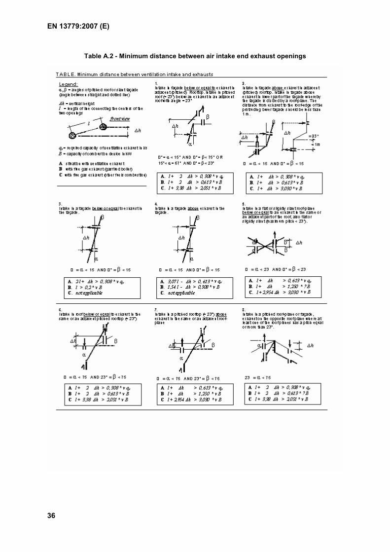
EN 13779:2007 (E)
36
Table A.2 - Minimum distance between air intake end exhaust openings
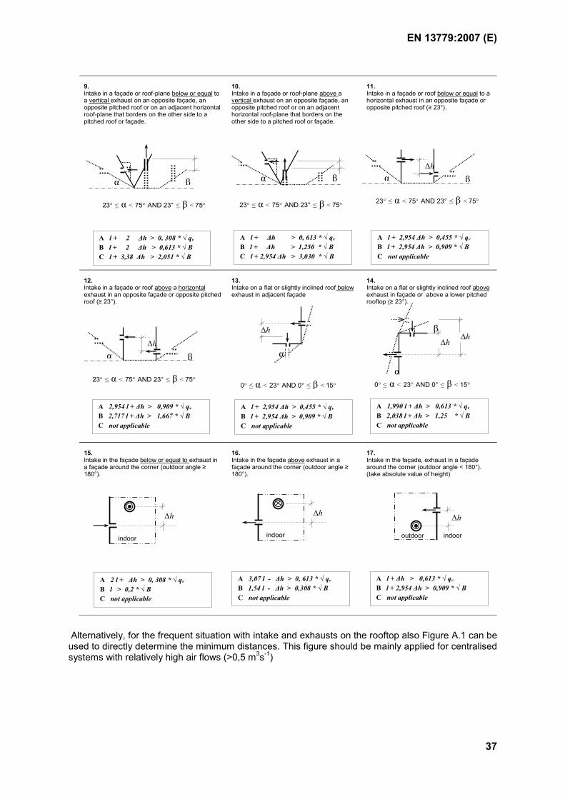
EN 13779:2007 (E)
37
9. Intake in a façade or roof-plane below or equal to a vertical exhaust on an opposite façade, an opposite pitched roof or on an adjacent horizontal roof-plane that borders on the other side to a pitched roof or façade.
10. Intake in a façade or roof-plane above a vertical exhaust on an opposite façade, an opposite pitched roof or on an adjacent horizontal roof-plane that borders on the other side to a pitched roof or façade.
11. Intake in a façade or roof below or equal to a horizontal exhaust in an opposite façade or opposite pitched roof (≥ 23°).
12. Intake in a façade or roof above a horizontal exhaust in an opposite façade or opposite pitched roof (≥ 23°).
13. Intake on a flat or slightly inclined roof below exhaust in adjacent façade
14. Intake on a flat or slightly inclined roof above exhaust in façade or above a lower pitched rooftop (≥ 23°).
15. Intake in the façade below or equal to exhaust in a façade around the corner (outdoor angle ≥ 180°).
16. Intake in the façade above exhaust in a façade around the corner (outdoor angle ≥ 180°).
17. Intake in the façade, exhaust in a façade around the corner (outdoor angle < 180°). (take absolute value of height)
23° ≤ α < 75° AND 23° ≤ β < 75°
α β α β
23° ≤ α < 75° AND 23° ≤ β < 75°
α∆h
β
23° ≤ α < 75° AND 23° ≤ β < 75°
A l + 2 ∆h > 0, 308 * √ qv
B l + 2 ∆h > 0,613 * √ B C l + 3,38 ∆h > 2,051 * √ B
A l + ∆h > 0, 613 * √ qv
B l + ∆h > 1,250 * √ B C l + 2,954 ∆h > 3,030 * √ B
A l + 2,954 ∆h > 0,455 * √ qv
B l + 2,954 ∆h > 0,909 * √ B C not applicable
α
∆h
0° ≤ α < 23° AND 0° ≤ β < 15° 0° ≤ α < 23° AND 0° ≤ β < 15°
∆h
indoor
∆h
indoor
∆h
outdoor indoor
A 2 l + ∆h > 0, 308 * √ qv
B l > 0,2 * √ B C not applicable
A 3,07 l - ∆h > 0, 613 * √ qv
B 1,54 l - ∆h > 0,308 * √ B C not applicable
A l + 2,954 ∆h > 0,455 * √ qv
B l + 2,954 ∆h > 0,909 * √ B C not applicable
A 1,990 l + ∆h > 0,613 * √ qv
B 2,038 l + ∆h > 1,25 * √ B C not applicable
A l + ∆h > 0,613 * √ qv
B l + 2,954 ∆h > 0,909 * √ B C not applicable
β
α
∆h ∆h
α ∆h
β
23° ≤ α < 75° AND 23° ≤ β < 75°
A 2,954 l + ∆h > 0,909 * √ qv
B 2,717 l + ∆h > 1,667 * √ B C not applicable
Alternatively, for the frequent situation with intake and exhausts on the rooftop also Figure A.1 can be used to directly determine the minimum distances. This figure should be mainly applied for centralised systems with relatively high air flows (>0,5 m3s-1)
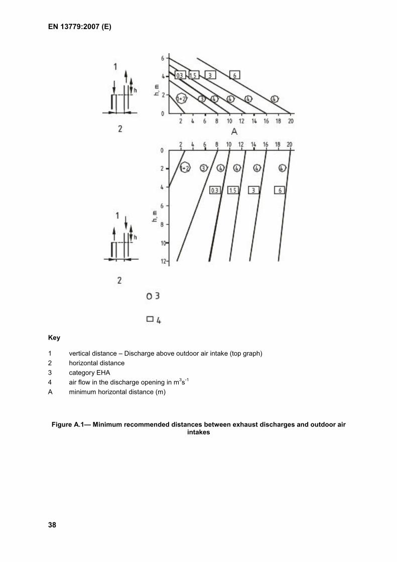
EN 13779:2007 (E)
38
Key
1 vertical distance – Discharge above outdoor air intake (top graph) 2 horizontal distance 3 category EHA 4 air flow in the discharge opening in m3s-1 A minimum horizontal distance (m)
Figure A.1— Minimum recommended distances between exhaust discharges and outdoor air intakes
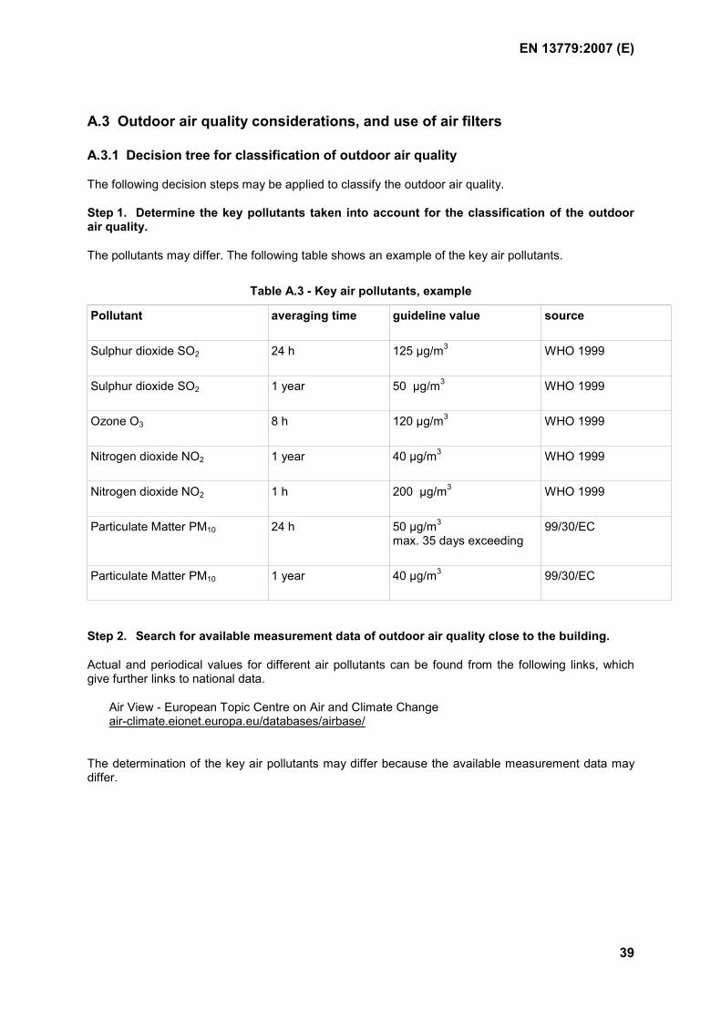
EN 13779:2007 (E)
39
A.3 Outdoor air quality considerations, and use of air filters
A.3.1 Decision tree for classification of outdoor air quality
The following decision steps may be applied to classify the outdoor air quality.
Step 1. Determine the key pollutants taken into account for the classification of the outdoor air quality.
The pollutants may differ. The following table shows an example of the key air pollutants.
Table A.3 - Key air pollutants, example
Pollutant averaging time guideline value source
Sulphur dioxide SO2 24 h 125 µg/m3 WHO 1999
Sulphur dioxide SO2 1 year 50 µg/m3 WHO 1999
Ozone O3 8 h 120 µg/m3 WHO 1999
Nitrogen dioxide NO2 1 year 40 µg/m3 WHO 1999
Nitrogen dioxide NO2 1 h 200 µg/m3 WHO 1999
Particulate Matter PM10 24 h 50 µg/m3
max. 35 days exceeding 99/30/EC
Particulate Matter PM10 1 year 40 µg/m3 99/30/EC
Step 2. Search for available measurement data of outdoor air quality close to the building.
Actual and periodical values for different air pollutants can be found from the following links, which give further links to national data.
Air View - European Topic Centre on Air and Climate Change air-climate.eionet.europa.eu/databases/airbase/
The determination of the key air pollutants may differ because the available measurement data may differ.
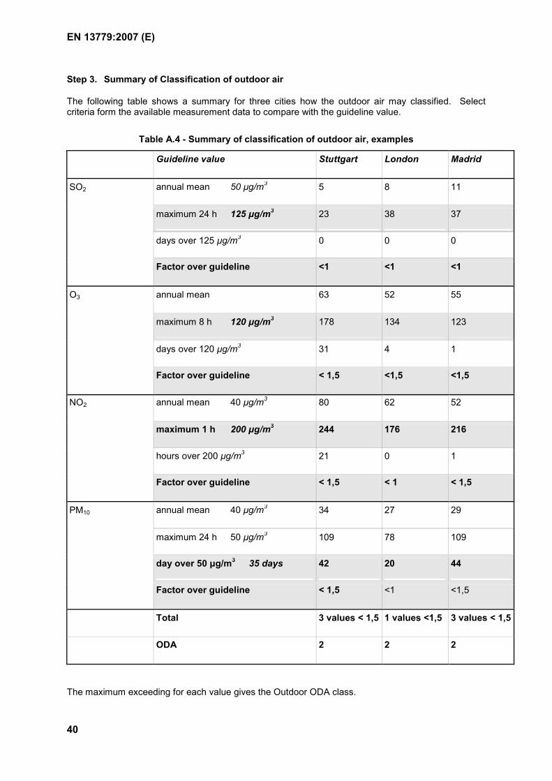
EN 13779:2007 (E)
40
Step 3. Summary of Classification of outdoor air
The following table shows a summary for three cities how the outdoor air may classified. Select criteria form the available measurement data to compare with the guideline value.
Table A.4 - Summary of classification of outdoor air, examples
Guideline value Stuttgart London Madrid
annual mean 50 µg/m3 5 8 11
maximum 24 h 125 µg/m3 23 38 37
days over 125 µg/m3 0 0 0
SO2
Factor over guideline <1 <1 <1
annual mean 63 52 55
maximum 8 h 120 µg/m3 178 134 123
days over 120 µg/m3 31 4 1
O3
Factor over guideline < 1,5 <1,5 <1,5
annual mean 40 µg/m3 80 62 52
maximum 1 h 200 µg/m3 244 176 216
hours over 200 µg/m3 21 0 1
NO2
Factor over guideline < 1,5 < 1 < 1,5
annual mean 40 µg/m3 34 27 29
maximum 24 h 50 µg/m3 109 78 109
day over 50 µg/m3 35 days 42 20 44
PM10
Factor over guideline < 1,5 <1 <1,5
Total 3 values < 1,5 1 values <1,5 3 values < 1,5
ODA 2 2 2
The maximum exceeding for each value gives the Outdoor ODA class.
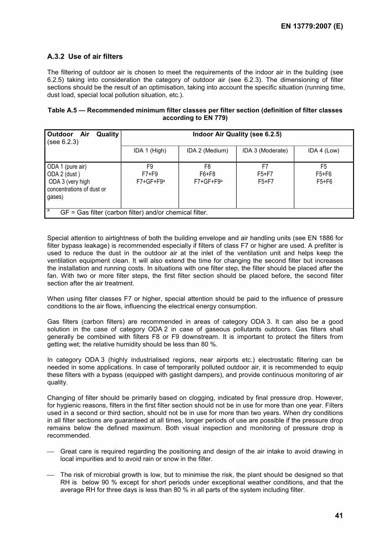
EN 13779:2007 (E)
41
A.3.2 Use of air filters
The filtering of outdoor air is chosen to meet the requirements of the indoor air in the building (see 6.2.5) taking into consideration the category of outdoor air (see 6.2.3). The dimensioning of filter sections should be the result of an optimisation, taking into account the specific situation (running time, dust load, special local pollution situation, etc.).
Table A.5 — Recommended minimum filter classes per filter section (definition of filter classes according to EN 779)
Indoor Air Quality (see 6.2.5) Outdoor Air Quality(see 6.2.3)
IDA 1 (High) IDA 2 (Medium) IDA 3 (Moderate) IDA 4 (Low)
ODA 1 (pure air) ODA 2 (dust ) ODA 3 (very high concentrations of dust or gases)
F9 F7+F9
F7+GF+F9a
F8 F6+F8
F7+GF+F9a
F7 F5+F7 F5+F7
F5 F5+F6 F5+F6
a GF = Gas filter (carbon filter) and/or chemical filter.
Special attention to airtightness of both the building envelope and air handling units (see EN 1886 for filter bypass leakage) is recommended especially if filters of class F7 or higher are used. A prefilter is used to reduce the dust in the outdoor air at the inlet of the ventilation unit and helps keep the ventilation equipment clean. It will also extend the time for changing the second filter but increases the installation and running costs. In situations with one filter step, the filter should be placed after the fan. With two or more filter steps, the first filter section should be placed before, the second filter section after the air treatment.
When using filter classes F7 or higher, special attention should be paid to the influence of pressure conditions to the air flows, influencing the electrical energy consumption.
Gas filters (carbon filters) are recommended in areas of category ODA 3. It can also be a good solution in the case of category ODA 2 in case of gaseous pollutants outdoors. Gas filters shall generally be combined with filters F8 or F9 downstream. It is important to protect the filters from getting wet; the relative humidity should be less than 80 %.
In category ODA 3 (highly industrialised regions, near airports etc.) electrostatic filtering can be needed in some applications. In case of temporarily polluted outdoor air, it is recommended to equip these filters with a bypass (equipped with gastight dampers), and provide continuous monitoring of air quality.
Changing of filter should be primarily based on clogging, indicated by final pressure drop. However, for hygienic reasons, filters in the first filter section should not be in use for more than one year. Filters used in a second or third section, should not be in use for more than two years. When dry conditions in all filter sections are guaranteed at all times, longer periods of use are possible if the pressure drop remains below the defined maximum. Both visual inspection and monitoring of pressure drop is recommended.
Great care is required regarding the positioning and design of the air intake to avoid drawing in local impurities and to avoid rain or snow in the filter.
The risk of microbial growth is low, but to minimise the risk, the plant should be designed so that RH is below 90 % except for short periods under exceptional weather conditions, and that the average RH for three days is less than 80 % in all parts of the system including filter.
EN 13779:2007 (E)
42
For hygienic reasons, inlet air should be filtered in two steps (at least for IDA 1 and IDA 2). The first filter in the air intake (prefilter) should be at class F5 but preferably class F7. The second filter step should be affected by a filter of at least class F7 but preferably class F9. If there is only one filtration step, the minimum requirement is class F7.
As regards recirculation air, at least F5 quality should be used to prevent the contamination of components in the system. However, whenever possible the filter in recirculation air should have the same quality as the comparable filter in the main stream.
For a protection of the extract and exhaust air system a filter of at least class F5 is needed. For regenerative heat recovery systems, use the same filter class in the extract air as in the outdoor air/ supply air.
Extract air from kitchen shall always be cleaned in a first step with a special filter for grease, which can be changed and cleaned easily.
Filters should not be installed directly after the fan outlet, or across places where the flow distribution over the cross-section is not uniform.
The final pressure drop is calculated and selected with regard to permitted variations in airflow, the filter’s life cycle costs and life cycle assessment. Because a coarse artificial dust is used in laboratory tests, a filter’s performance in real operating conditions will differ with regard to efficiency, dust holding capacity and other test results from laboratory trials. Efficiency shall not deteriorate below defined values.
Filters should be replaced when the pressure loss reaches the specified final pressure loss, or when the following hygiene interval is reached, if this occurs earlier. If the hours of operation are predictable, this may also be used as a replacement criterion as follows:
The filter in the first filtration step should be replaced after 2 000 h of operation or a maximum of one year.
The filter in the second filtration step, as well as filters in exhaust or recycled air systems, should be changed after 4,000 hour operation or a maximum of two years.
Filter Replacement: For hygienic reasons, the filter should be replaced after the main pollen and spore season in the autumn. If requirements are stringent, filters can also be changed in the spring after the heating season to eliminate odorous combustion products.
Filters should be replaced carefully, using protective equipment, to prevent the escape of trapped impurities.
Dumping/Disposal: Filters may be incinerated in well-filtered furnaces in order to burn trapped impurities, reduce waste and recover energy. In disposal of air filters, existing environmental regulations have to be followed.
Heat recovery systems should always be protected with a filter of class F6 or higher. Rotating heat recovery units should be equipped with cleaning sections.
Leaks in a filter section significantly decrease the efficiency of filtering. Therefore it is important to fulfil the requirements for airtightness and bypass leakage given in EN 1886.
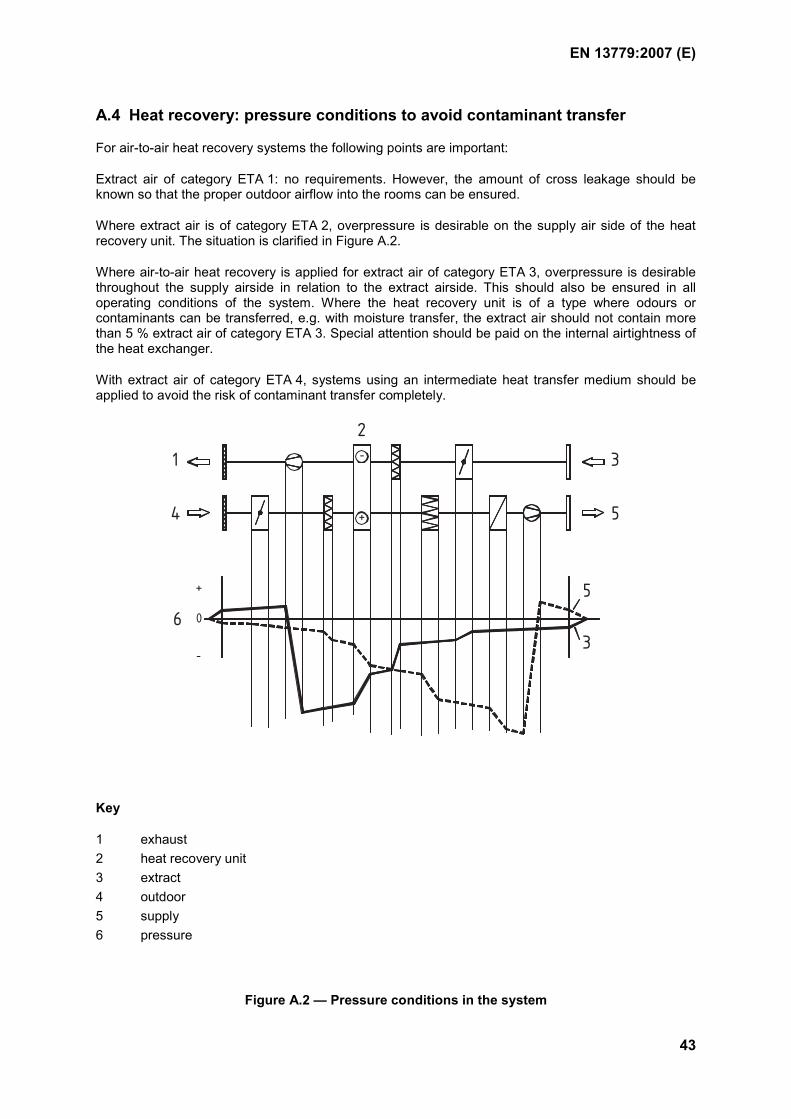
EN 13779:2007 (E)
43
A.4 Heat recovery: pressure conditions to avoid contaminant transfer
For air-to-air heat recovery systems the following points are important:
Extract air of category ETA 1: no requirements. However, the amount of cross leakage should be known so that the proper outdoor airflow into the rooms can be ensured.
Where extract air is of category ETA 2, overpressure is desirable on the supply air side of the heat recovery unit. The situation is clarified in Figure A.2.
Where air-to-air heat recovery is applied for extract air of category ETA 3, overpressure is desirable throughout the supply airside in relation to the extract airside. This should also be ensured in all operating conditions of the system. Where the heat recovery unit is of a type where odours or contaminants can be transferred, e.g. with moisture transfer, the extract air should not contain more than 5 % extract air of category ETA 3. Special attention should be paid on the internal airtightness of the heat exchanger.
With extract air of category ETA 4, systems using an intermediate heat transfer medium should be applied to avoid the risk of contaminant transfer completely.
0
+
-
-
+
1
2
3
4 5
6
5
3
Key
1 exhaust 2 heat recovery unit 3 extract 4 outdoor 5 supply 6 pressure
Figure A.2 — Pressure conditions in the system
EN 13779:2007 (E)
44
A.5 Removal of extract air
In order not to allow impurities to spread in the building through the air ducts or the ventilation system, ducts should be designed and maintained in accordance with EN 12097, and air should be removed from the building in accordance with the following requirements related to the various extract air categories.
Category ETA 1: Extract air can be collected into a common duct.
Category ETA 2: Extract air can be collected into a common duct.
Category ETA 3: Extract air is generally conducted through individual ducts, or common ducts from different spaces of the same category, outdoors or into a collection duct or an extract air chamber
Category ETA 4: Extract air is conducted to the outdoors through individual extract air ducts.
If air from various extract air categories is combined into a common duct, the extract air in that duct is classified according to the category indicating the heaviest pollution, provided that the relative content of this exceeds 10 % of the total extract airflow.
Minimum extract air rates from kitchens and hygiene rooms are specified in national regulations and guidelines. If nothing is specified, the following default minimum extract air rates should be applied:
Table A.6 — Design values for extract air rates
Kind of use Unit Typical range Default value for design Kitchen - simple use (e.g. kitchen for making hot drinks)
l.s-1 > 20 30
- professional use a a a
Toilet/Washroom b - per closet or urinal l.s-1 > 6,7 15 - per floor area l.s-1.m-2 > 1,4 3 a The extract air rates for kitchen shall be designed according to the specific situation. b In use for at least 50 % of the time. With shorter running times higher rates are needed. Lower values are possible with direct extract air at the closet (typical value: 3 to 6 l3.s-1 per closet or urinal).
A.6 Reuse of extract air and use of transfer air
The reuse of extract air is dependent on the specific situation.
In order to achieve low energy consumption, the supply air rate should normally be as low as possible and any emissions that are not desirable (e.g. heat, pollution, and moisture) should be removed by measures at the source or by direct extraction in a closed system. In this case, and in most cases in which good air quality in the room is needed, no recirculation of air should be used. If a space is heated or cooled before its use, and this is done with a ventilation system, it should be achieved mainly with recirculated air.
Based on the classification of exhaust and extract air in 6.2.2, the uses of air in Table A.7 can be noted.
EN 13779:2007 (E)
45
Table A.7 — Re-use of extract air and use of transfer air
Categorya Comment concerning the possible re-use of the air ETA 1 This air is suitable for recirculated and transfer air ETA 2 This air is not suitable for recirculated air but it can be used for transfer air into
toilets, wash rooms, garages and other similar spaces
ETA 3 This air is not suitable for recirculated or transfer air ETA 4 This air is not suitable for recirculated or transfer air a See Table 4.
The use of recirculated air within the same space is allowed in category ETA 1 without restrictions and in category ETA 2 on condition that the quality of recirculated air is monitored.
When no re-use of extract air is allowed, the design also has to ensure that no unintended recirculation takes place. Special attention needs to be given to the airtightness of any heat recovery systems.
A.7 Thermal insulation of the system
All ducts, pipes and units with a significant temperature difference between the medium and the surrounding should be insulated against heat transfer.
The construction of the insulation should be such that:
condensation does not occur in the construction itself nor on the surface;
the insulation is protected against damage;
proper cleaning of ducts is still possible;
production and disposal causes as little harm to the environment as possible.
As a rule, inside insulation should be avoided for outside air, recirculation air and supply air.
A.8 Airtightness of the system
A.8.1 General
The classification and testing of air-tightness of circular ducts is described in EN 12237, and of rectangular ducts in EN 1507. This basic classification is applicable also to other components and also to the whole system. The requirements and testing of the airtightness of air handling units, including filter bypass leakage, are described in EN 1886.
The tightness class should be selected so that neither infiltration into an installation operating at negative pressure, nor exfiltration from an installation operating at positive pressure, exceeds a defined percentage of the total system flow rate under operating conditions. In order to avoid excessive energy losses and to have a controlled airflow in the system, this percentage should normally be less than 2 %, corresponding generally class B according to EN 12237 and EN 1507. Guidance for estimating the leakage rates and its influence of air flows and energy consumption is presented in EN 15242 and EN 15241.
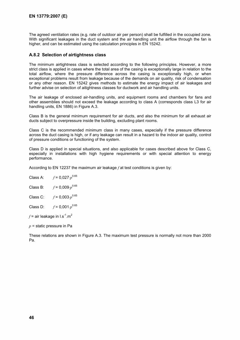
EN 13779:2007 (E)
46
The agreed ventilation rates (e.g. rate of outdoor air per person) shall be fulfilled in the occupied zone. With significant leakages in the duct system and the air handling unit the airflow through the fan is higher, and can be estimated using the calculation principles in EN 15242.
A.8.2 Selection of airtightness class
The minimum airtightness class is selected according to the following principles. However, a more strict class is applied in cases where the total area of the casing is exceptionally large in relation to the total airflow, where the pressure difference across the casing is exceptionally high, or when exceptional problems result from leakage because of the demands on air quality, risk of condensation or any other reason. EN 15242 gives methods to estimate the energy impact of air leakages and further advise on selection of aitightness classes for ductwork and air handling units.
The air leakage of enclosed air-handling units, and equipment rooms and chambers for fans and other assemblies should not exceed the leakage according to class A (corresponds class L3 for air handling units, EN 1886) in Figure A.3.
Class B is the general minimum requirement for air ducts, and also the minimum for all exhaust air ducts subject to overpressure inside the building, excluding plant rooms.
Class C is the recommended minimum class in many cases, especially if the pressure difference across the duct casing is high, or if any leakage can result in a hazard to the indoor air quality, control of pressure conditions or functioning of the system.
Class D is applied in special situations, and also applicable for cases described above for Class C, especially in installations with high hygiene requirements or with special attention to energy performance.
According to EN 12237 the maximum air leakage f at test conditions is given by:
Class A: f = 0,027⋅p0.65
Class B: f = 0,009⋅p0.65
Class C: f = 0,003⋅p0.65
Class D: f = 0,001⋅p0.65
f = air leakage in l.s-1.m2
p = static pressure in Pa
These relations are shown in Figure A.3. The maximum test pressure is normally not more than 2000 Pa.
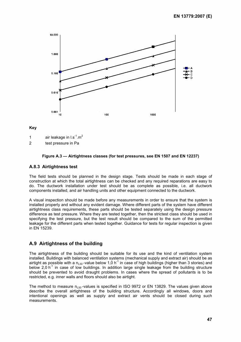
EN 13779:2007 (E)
47
Key
1 air leakage in l.s-1.m2 2 test pressure in Pa
Figure A.3 — Airtightness classes (for test pressures, see EN 1507 and EN 12237)
A.8.3 Airtightness test
The field tests should be planned in the design stage. Tests should be made in each stage of construction at which the total airtightness can be checked and any required reparations are easy to do. The ductwork installation under test should be as complete as possible, i.e. all ductwork components installed, and air handling units and other equipment connected to the ductwork.
A visual inspection should be made before any measurements in order to ensure that the system is installed properly and without any evident damage. Where different parts of the system have different airtightness class requirements, these parts should be tested separately using the design pressure difference as test pressure. Where they are tested together, then the strictest class should be used in specifying the test pressure, but the test result should be compared to the sum of the permitted leakage for the different parts when tested together. Guidance for tests for regular inspection is given in EN 15239.
A.9 Airtightness of the building
The airtightness of the building should be suitable for its use and the kind of ventilation system installed. Buildings with balanced ventilation systems (mechanical supply and extract air) should be as airtight as possible with a nL50 -value below 1,0 h-1 in case of high buildings (higher than 3 stories) and below 2,0 h-1 in case of low buildings. In addition large single leakage from the building structure should be prevented to avoid draught problems. In cases where the spread of pollutants is to be restricted, e.g. inner walls and floors should also be airtight.
The method to measure nL50 -values is specified in ISO 9972 or EN 13829. The values given above describe the overall airtightness of the building structure. Accordingly all windows, doors and intentional openings as well as supply and extract air vents should be closed during such measurements.
EN 13779:2007 (E)
48
A.10 Pressure conditions within the system and the building
A.10.1 General
The relative pressures of the building, different spaces and the ventilation system should be designed so that spreading of odours and impurities in harmful amounts or concentrations is prevented.
No significant changes to the pressure conditions are allowed due to changes in weather conditions. The airtightness of the building envelope, floors and partition walls, which affect the pressure conditions, should be studied and defined in the design stage, taking account of both temperature and wind conditions. Pressure differences caused by smoke control systems are not covered in this standard.
A.10.2 Building
In situations with no special requirements or emissions, ventilation systems should be designed for neutral pressure conditions in the building. The pressure difference from indoors to outdoors or between rooms should not exceed 20 Pa.
In areas where expected outdoor air pollution is high (Categories ODA 2 to 3) or in areas where un-derpressure can cause the potential risk of an increase in the concentration of e.g radon, the underpressure indoors should be designed to be a minimum. Alternatively, the building should be designed for slight overpressure (In severe climates it should be checked that internal overpressure does not cause moisture damage to the structures).
Certain spaces (also buildings for human occupancy) should be designed for overpressure in relation to outdoors or adjacent spaces. Clean rooms, rooms for sensitive electronic/data processing equipment are for examples of such spaces.
The pressure conditions should be continuously monitored in spaces where heavy emission of impu-rities occurs. The air pressures in stairways, corridors and other passages should be dimensioned so that they will not cause airflows from one room or apartment to another.
A.10.3 Indoors
The relative pressures of the interior room spaces should be specified in order that air flows from the cleaner spaces into those spaces where more impurities are released.
A.10.4 System
Impurities should not be allowed to spread in the building through air ducts or the ventilation system. Different ventilation systems should not be combined within the same zone of a building in such a way that the pressure conditions within this zone of the building become uncontrolled in certain operating conditions.
High-rise buildings should be divided into separate ventilation zones with a specified maximum height. The vertical distance (D) between the lowest and highest intake in the same zone should not exceed the following:
minout,amax
600θθ −
=D (A.2)
where: Dmax is the vertical distance in m
θa is the air temperature in the room in °C
θout,min is the design outdoor temperature for winter condition in °C
EN 13779:2007 (E)
49
EXAMPLE: When the air temperature in the room is 21 °C and the design outdoor temperature –14 °C, then the vertical distance between lowest and highest intake should not exceed 17 m.
Alternatively, the system can be equipped with constant flow dampers or similar devices, which automatically compensate for the stack effect.
A.10.5 Pressure conditions in units and systems
Pressure drops for filters and filter sections, for dampers, damper sections and mixing sections in air handling units should be specified in accordance with EN 13053. For systems with variable airflow, additional requirements are specified for the following:
maximum variation for pressure difference and the ratio of exhaust and supply airflows
pressure monitoring
The influence of variations of pressure drop on the airflows, due to pollution e.g. dust accumulation or different damper positions in the damper or mixing section, should be determined and estimated. No significant changes in the airflows (generally not more than ± 10 % of the total supply or exhaust airflow) or to the pressure conditions in the building should be allowed due to changes in the pressure drops in the unit and system.
A.10.6 Ductwork
The extract air ducts inside the building (excluding the discharge duct in the fan room) are usually designed for negative pressure.
Extract air of category ETA 1 and ETA 2 can, however, be ducted under positive pressure on the condition that the tightness of ducts are to class C in accordance with EN 12237, and that there are no supply air ducts operating at a lower pressure in the same shaft.
Extract air of category ETA 3 or ETA 4 should not be ducted within the occupied part of the building under positive pressure. The extract air ducts of mechanical ventilation systems should be equipped with devices which close automatically when the ventilation stops, in order to prevent back draught and uncontrolled ventilation, at least when the extract duct cross section is greater than 0,06 m2.
The overall ductwork system should be designed to minimise energy use employing static regain principles to reduce the amount of damper control required to produce the specified air distribution in the ductwork.
A.11 Demand controlled ventilation
Practical experience shows that adapting the ventilation to the actual requirement can very often substantially reduce the energy consumption of a ventilation system.
In situations with variable demand, the ventilation system can be operated in such a way that given criteria in the room are met. In rooms for the occupancy of people, the following sensors can be adopted for ventilation control according to actual demand:
movement sensors;
counting sensors;
CO2 sensors (mainly used for rooms with no smoking);
mixed gas sensors (also used in rooms with smoking);
infrared sensors.
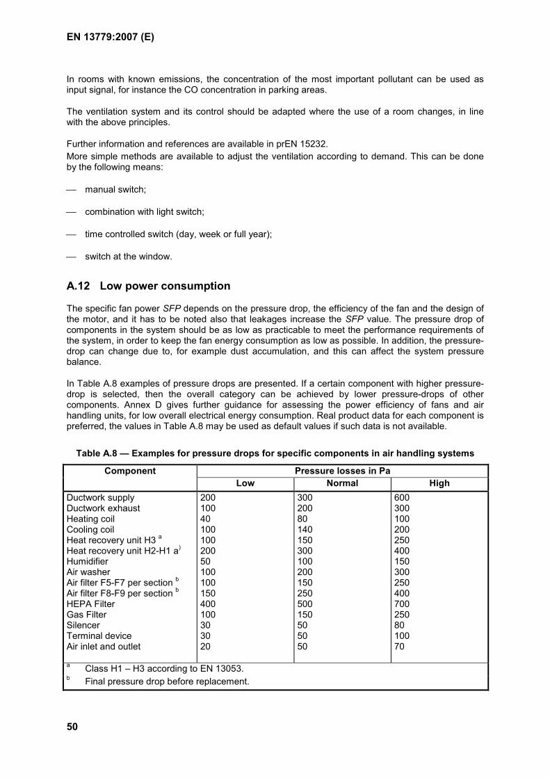
EN 13779:2007 (E)
50
In rooms with known emissions, the concentration of the most important pollutant can be used as input signal, for instance the CO concentration in parking areas.
The ventilation system and its control should be adapted where the use of a room changes, in line with the above principles.
Further information and references are available in prEN 15232. More simple methods are available to adjust the ventilation according to demand. This can be done by the following means:
manual switch;
combination with light switch;
time controlled switch (day, week or full year);
switch at the window.
A.12 Low power consumption
The specific fan power SFP depends on the pressure drop, the efficiency of the fan and the design of the motor, and it has to be noted also that leakages increase the SFP value. The pressure drop of components in the system should be as low as practicable to meet the performance requirements of the system, in order to keep the fan energy consumption as low as possible. In addition, the pressure-drop can change due to, for example dust accumulation, and this can affect the system pressure balance.
In Table A.8 examples of pressure drops are presented. If a certain component with higher pressure-drop is selected, then the overall category can be achieved by lower pressure-drops of other components. Annex D gives further guidance for assessing the power efficiency of fans and air handling units, for low overall electrical energy consumption. Real product data for each component is preferred, the values in Table A.8 may be used as default values if such data is not available.
Table A.8 — Examples for pressure drops for specific components in air handling systems
Pressure losses in Pa Component Low Normal High
Ductwork supply Ductwork exhaust Heating coil Cooling coil Heat recovery unit H3 a Heat recovery unit H2-H1 a)
Humidifier Air washer Air filter F5-F7 per section b Air filter F8-F9 per section b
HEPA Filter Gas Filter Silencer Terminal device Air inlet and outlet
200 100 40 100 100 200 50 100 100 150 400 100 30 30 20
300 200 80 140 150 300 100 200 150 250 500 150 50 50 50
600 300 100 200 250 400 150 300 250 400 700 250 80 100 70
a Class H1 – H3 according to EN 13053. b Final pressure drop before replacement.
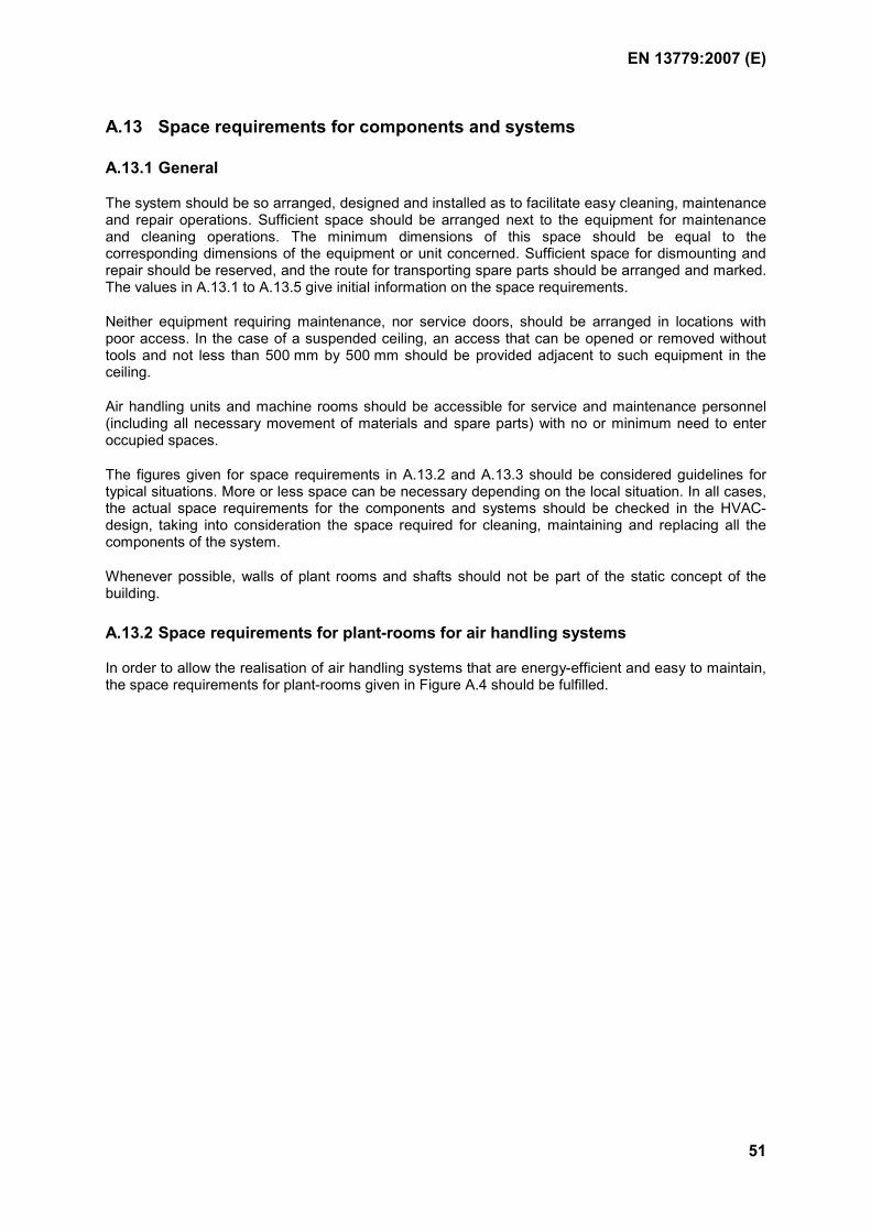
EN 13779:2007 (E)
51
A.13 Space requirements for components and systems
A.13.1 General
The system should be so arranged, designed and installed as to facilitate easy cleaning, maintenance and repair operations. Sufficient space should be arranged next to the equipment for maintenance and cleaning operations. The minimum dimensions of this space should be equal to the corresponding dimensions of the equipment or unit concerned. Sufficient space for dismounting and repair should be reserved, and the route for transporting spare parts should be arranged and marked. The values in A.13.1 to A.13.5 give initial information on the space requirements.
Neither equipment requiring maintenance, nor service doors, should be arranged in locations with poor access. In the case of a suspended ceiling, an access that can be opened or removed without tools and not less than 500 mm by 500 mm should be provided adjacent to such equipment in the ceiling.
Air handling units and machine rooms should be accessible for service and maintenance personnel (including all necessary movement of materials and spare parts) with no or minimum need to enter occupied spaces.
The figures given for space requirements in A.13.2 and A.13.3 should be considered guidelines for typical situations. More or less space can be necessary depending on the local situation. In all cases, the actual space requirements for the components and systems should be checked in the HVAC-design, taking into consideration the space required for cleaning, maintaining and replacing all the components of the system.
Whenever possible, walls of plant rooms and shafts should not be part of the static concept of the building.
A.13.2 Space requirements for plant-rooms for air handling systems
In order to allow the realisation of air handling systems that are energy-efficient and easy to maintain, the space requirements for plant-rooms given in Figure A.4 should be fulfilled.
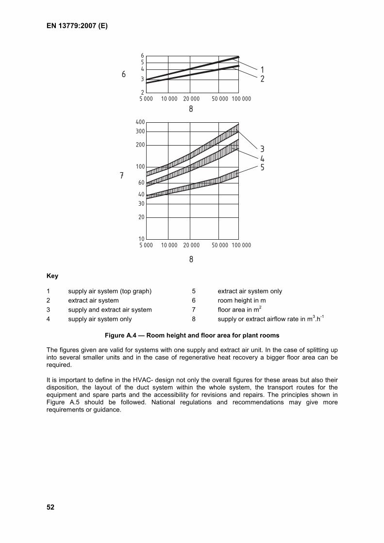
EN 13779:2007 (E)
52
10 000 50 00020 000 100 000
400
300
200
100
60
40
30
20
10
5 000 10 000 20 000 50 000 100 000
654
3
2
5 000
12
45
3
6
7
8
8
Key
1 supply air system (top graph) 5 extract air system only 2 extract air system 6 room height in m 3 supply and extract air system 7 floor area in m2
4 supply air system only 8 supply or extract airflow rate in m3.h-1
Figure A.4 — Room height and floor area for plant rooms
The figures given are valid for systems with one supply and extract air unit. In the case of splitting up into several smaller units and in the case of regenerative heat recovery a bigger floor area can be required.
It is important to define in the HVAC- design not only the overall figures for these areas but also their disposition, the layout of the duct system within the whole system, the transport routes for the equipment and spare parts and the accessibility for revisions and repairs. The principles shown in Figure A.5 should be followed. National regulations and recommendations may give more requirements or guidance.
EN 13779:2007 (E)
53
b=
=
1
2
Key
1 b = 0,4 x height of the unit, minimum 0,5 m as a default 2 service space
Figure A.5 — Disposition of air handling systems (plan view)
A.13.3 Space requirements for refrigerating and water distribution plants
The space requirements for refrigerating and water distribution plants should be in accordance with Figure A.6.
The areas given are valid for the refrigerating unit, the cold water pumps and the cold water distribution system. The space requirement for pumps and distribution systems for the heating is not included.
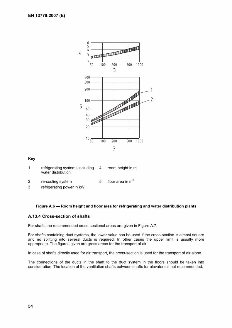
EN 13779:2007 (E)
54
1000200 5001005010
20
3040
60
100
200
300400
2
3456
100050020010050
1
2
3
3
4
5
Key
1 refrigerating systems including water distribution
4 room height in m
2 re-cooling system 5 floor area in m2
3 refrigerating power in kW
Figure A.6 — Room height and floor area for refrigerating and water distribution plants
A.13.4 Cross-section of shafts
For shafts the recommended cross-sectional areas are given in Figure A.7.
For shafts containing duct systems, the lower value can be used if the cross-section is almost square and no splitting into several ducts is required. In other cases the upper limit is usually more appropriate. The figures given are gross areas for the transport of air.
In case of shafts directly used for air transport, the cross-section is used for the transport of air alone.
The connections of the ducts in the shaft to the duct system in the floors should be taken into consideration. The location of the ventilation shafts between shafts for elevators is not recommended.
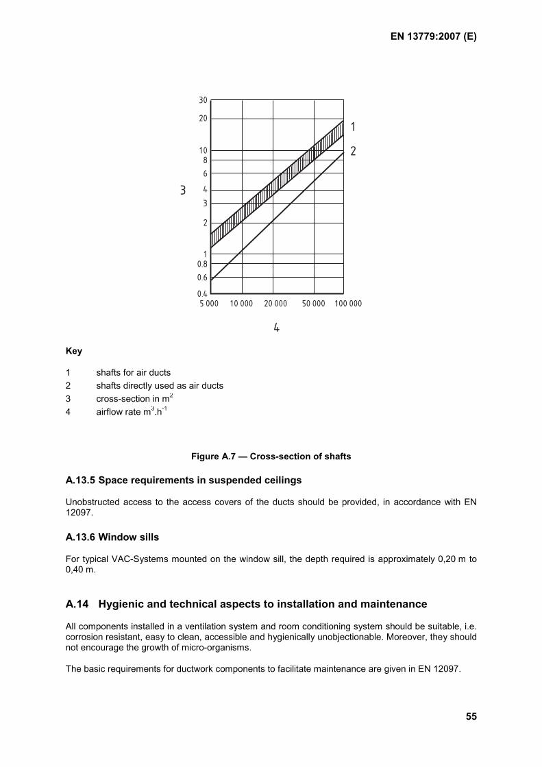
EN 13779:2007 (E)
55
30
20
108
6
4
3
2
10.8
0.6
0.45 000 10 000 20 000 50 000 100 000
1
2
3
4
Key
1 shafts for air ducts 2 shafts directly used as air ducts 3 cross-section in m2
4 airflow rate m3.h-1
Figure A.7 — Cross-section of shafts
A.13.5 Space requirements in suspended ceilings
Unobstructed access to the access covers of the ducts should be provided, in accordance with EN 12097.
A.13.6 Window sills
For typical VAC-Systems mounted on the window sill, the depth required is approximately 0,20 m to 0,40 m.
A.14 Hygienic and technical aspects to installation and maintenance
All components installed in a ventilation system and room conditioning system should be suitable, i.e. corrosion resistant, easy to clean, accessible and hygienically unobjectionable. Moreover, they should not encourage the growth of micro-organisms.
The basic requirements for ductwork components to facilitate maintenance are given in EN 12097.
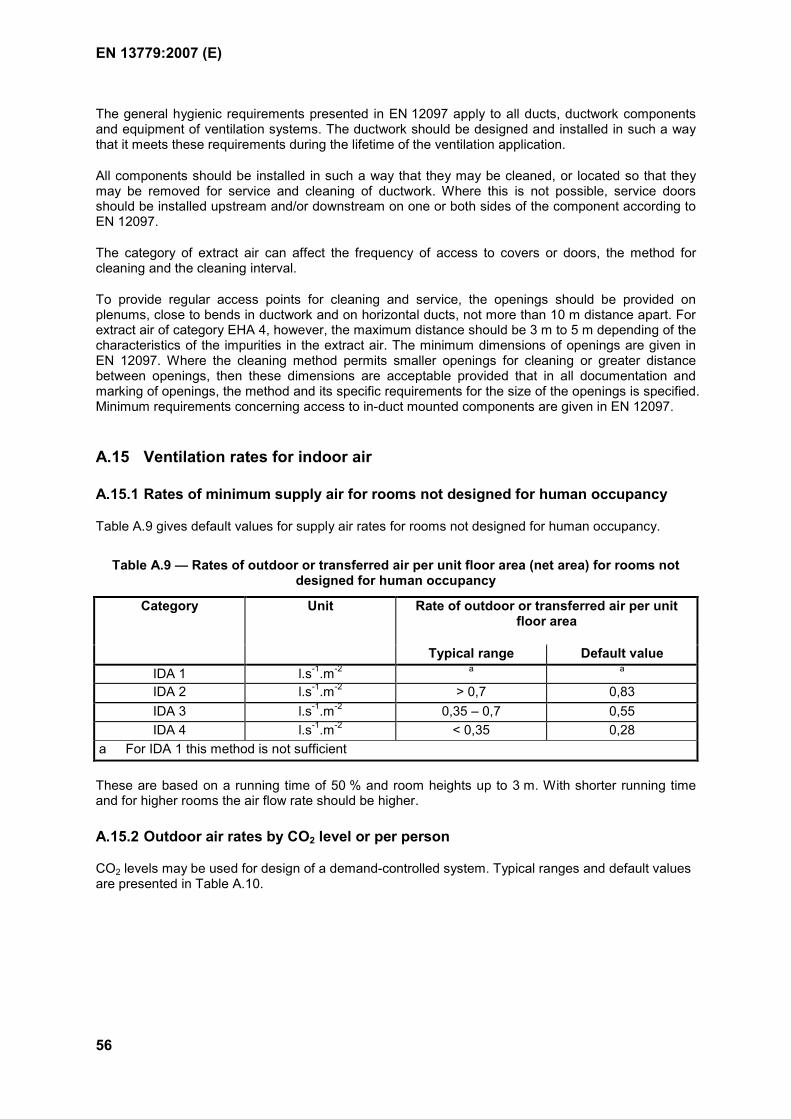
EN 13779:2007 (E)
56
The general hygienic requirements presented in EN 12097 apply to all ducts, ductwork components and equipment of ventilation systems. The ductwork should be designed and installed in such a way that it meets these requirements during the lifetime of the ventilation application.
All components should be installed in such a way that they may be cleaned, or located so that they may be removed for service and cleaning of ductwork. Where this is not possible, service doors should be installed upstream and/or downstream on one or both sides of the component according to EN 12097.
The category of extract air can affect the frequency of access to covers or doors, the method for cleaning and the cleaning interval.
To provide regular access points for cleaning and service, the openings should be provided on plenums, close to bends in ductwork and on horizontal ducts, not more than 10 m distance apart. For extract air of category EHA 4, however, the maximum distance should be 3 m to 5 m depending of the characteristics of the impurities in the extract air. The minimum dimensions of openings are given in EN 12097. Where the cleaning method permits smaller openings for cleaning or greater distance between openings, then these dimensions are acceptable provided that in all documentation and marking of openings, the method and its specific requirements for the size of the openings is specified. Minimum requirements concerning access to in-duct mounted components are given in EN 12097.
A.15 Ventilation rates for indoor air
A.15.1 Rates of minimum supply air for rooms not designed for human occupancy
Table A.9 gives default values for supply air rates for rooms not designed for human occupancy.
Table A.9 — Rates of outdoor or transferred air per unit floor area (net area) for rooms not designed for human occupancy
Unit Rate of outdoor or transferred air per unit floor area
Category
Typical range Default valueIDA 1 l.s-1.m-2 a a
IDA 2 l.s-1.m-2 > 0,7 0,83 IDA 3 l.s-1.m-2 0,35 – 0,7 0,55 IDA 4 l.s-1.m-2 < 0,35 0,28
a For IDA 1 this method is not sufficient
These are based on a running time of 50 % and room heights up to 3 m. With shorter running time and for higher rooms the air flow rate should be higher.
A.15.2 Outdoor air rates by CO2 level or per person
CO2 levels may be used for design of a demand-controlled system. Typical ranges and default values are presented in Table A.10.
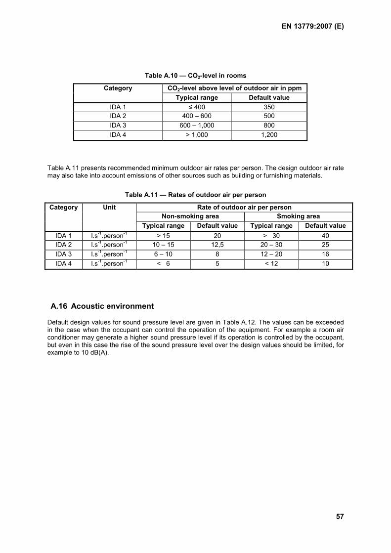
EN 13779:2007 (E)
57
Table A.10 — CO2-level in rooms
CO2-level above level of outdoor air in ppm Category Typical range Default value
IDA 1 ≤ 400 350 IDA 2 400 – 600 500 IDA 3 600 – 1,000 800 IDA 4 > 1,000 1,200
Table A.11 presents recommended minimum outdoor air rates per person. The design outdoor air rate may also take into account emissions of other sources such as building or furnishing materials.
Table A.11 — Rates of outdoor air per person
Rate of outdoor air per person Non-smoking area Smoking area
Category Unit
Typical range Default value Typical range Default valueIDA 1 l.s-1.person-1 > 15 20 > 30 40 IDA 2 l.s-1.person-1 10 – 15 12,5 20 – 30 25 IDA 3 l.s-1.person-1 6 – 10 8 12 – 20 16 IDA 4 l.s-1.person-1 < 6 5 < 12 10
A.16 Acoustic environment
Default design values for sound pressure level are given in Table A.12. The values can be exceeded in the case when the occupant can control the operation of the equipment. For example a room air conditioner may generate a higher sound pressure level if its operation is controlled by the occupant, but even in this case the rise of the sound pressure level over the design values should be limited, for example to 10 dB(A).
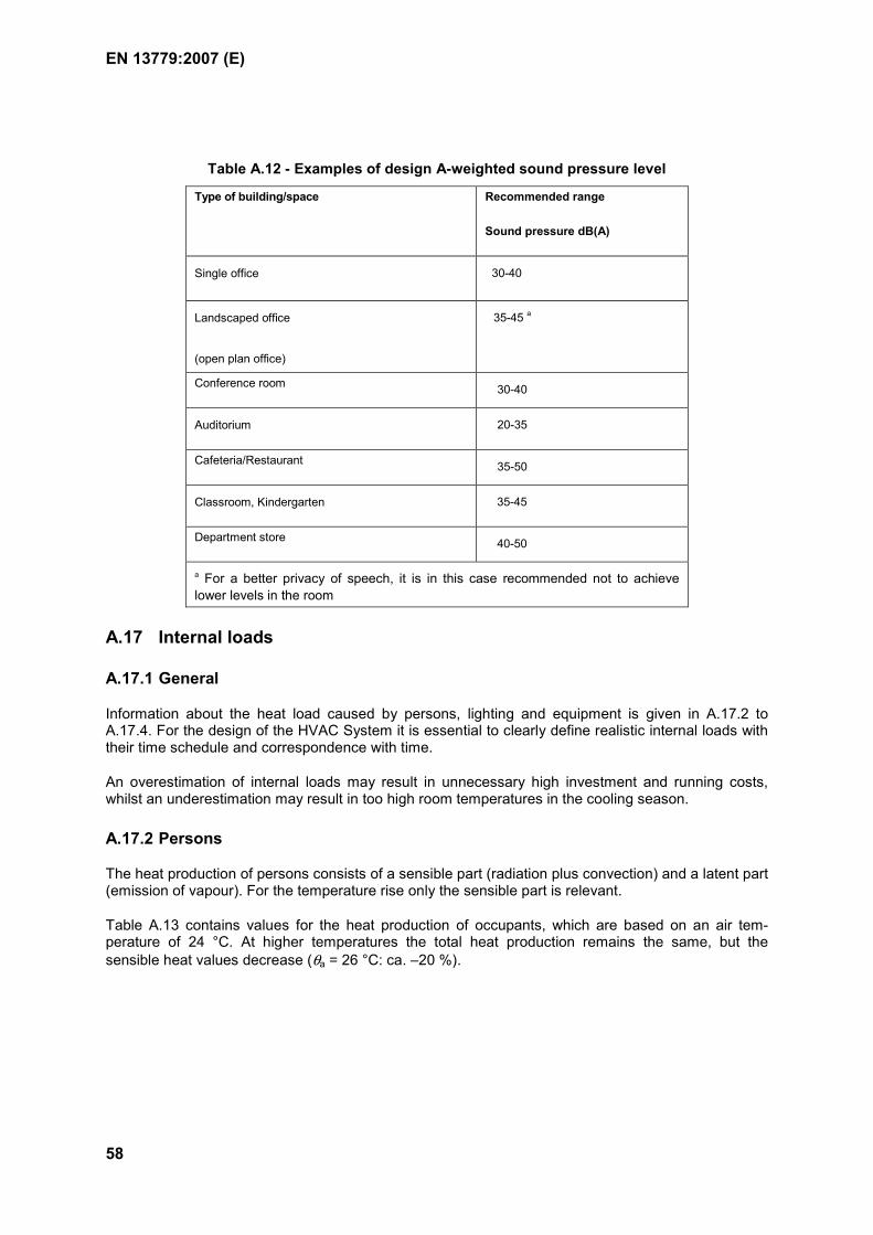
EN 13779:2007 (E)
58
Table A.12 - Examples of design A-weighted sound pressure level
Type of building/space Recommended range
Sound pressure dB(A)
Single office 30-40
Landscaped office
(open plan office)
35-45 a
Conference room 30-40
Auditorium 20-35
Cafeteria/Restaurant 35-50
Classroom, Kindergarten 35-45
Department store 40-50
a For a better privacy of speech, it is in this case recommended not to achieve lower levels in the room
A.17 Internal loads
A.17.1 General
Information about the heat load caused by persons, lighting and equipment is given in A.17.2 to A.17.4. For the design of the HVAC System it is essential to clearly define realistic internal loads with their time schedule and correspondence with time.
An overestimation of internal loads may result in unnecessary high investment and running costs, whilst an underestimation may result in too high room temperatures in the cooling season.
A.17.2 Persons
The heat production of persons consists of a sensible part (radiation plus convection) and a latent part (emission of vapour). For the temperature rise only the sensible part is relevant.
Table A.13 contains values for the heat production of occupants, which are based on an air tem-perature of 24 °C. At higher temperatures the total heat production remains the same, but the sensible heat values decrease (θa = 26 °C: ca. –20 %).
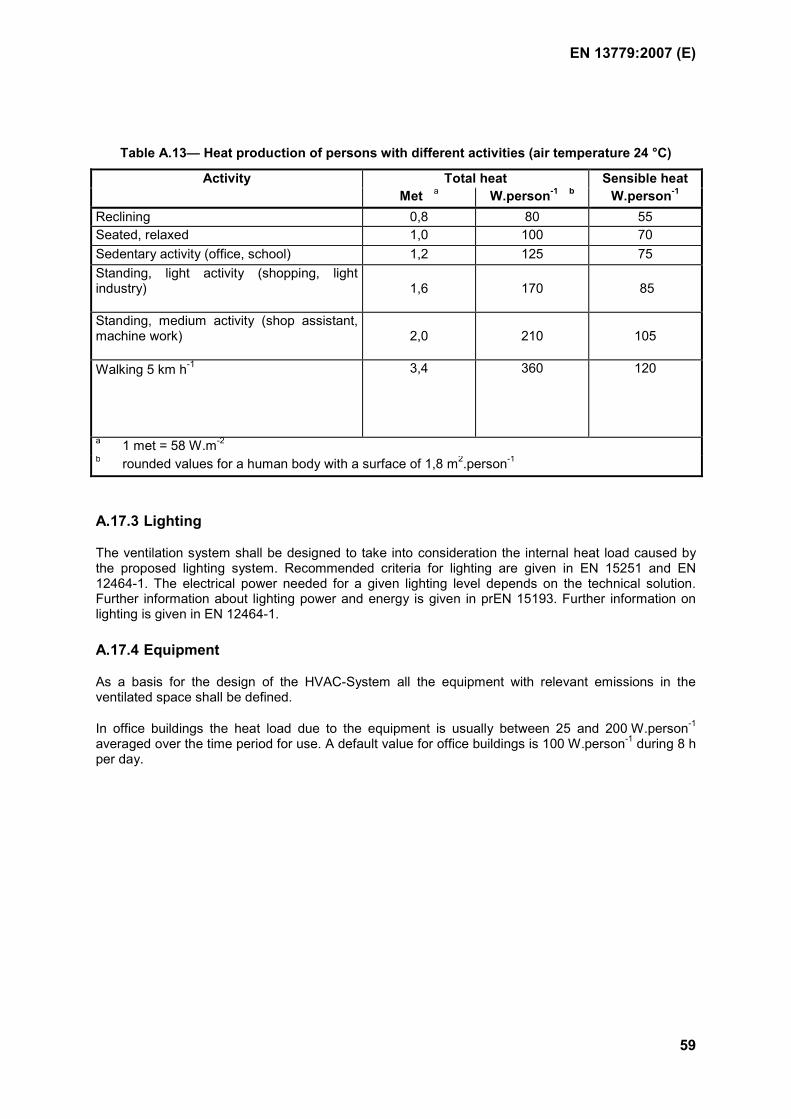
EN 13779:2007 (E)
59
Table A.13— Heat production of persons with different activities (air temperature 24 °C)
Total heat Sensible heatActivity Met a W.person-1 b W.person-1
Reclining 0,8 80 55 Seated, relaxed 1,0 100 70 Sedentary activity (office, school) 1,2 125 75 Standing, light activity (shopping, light industry)
1,6
170
85
Standing, medium activity (shop assistant, machine work)
2,0
210
105
Walking 5 km h-1 3,4 360 120
a 1 met = 58 W.m-2 b rounded values for a human body with a surface of 1,8 m2.person-1
A.17.3 Lighting
The ventilation system shall be designed to take into consideration the internal heat load caused by the proposed lighting system. Recommended criteria for lighting are given in EN 15251 and EN 12464-1. The electrical power needed for a given lighting level depends on the technical solution. Further information about lighting power and energy is given in prEN 15193. Further information on lighting is given in EN 12464-1.
A.17.4 Equipment
As a basis for the design of the HVAC-System all the equipment with relevant emissions in the ventilated space shall be defined.
In office buildings the heat load due to the equipment is usually between 25 and 200 W.person-1 averaged over the time period for use. A default value for office buildings is 100 W.person-1 during 8 h per day.
EN 13779:2007 (E)
60
Annex B (informative)
Economic aspects
B.1 General
The choice of a heating and ventilation system for any building is based on the best functioning equipment at the most reasonable costs. The calculation of the costs should be by the use of a proven and agreed method.
Further information is given in prEN 15459.
B.2 Life spans and maintenance costs for installations and equipment
The life spans and the maintenance cost of equipment depend on the following:
a) quality of the equipment
b) sizing and selection of the equipment
c) degree of utilisation
d) quality and method of maintenance
As a general recommendation the life spans and annual maintenance costs given in prEN 15459 can be used in the calculation of life cycle costs. It is, however, important to consider the above-mentioned factors and the life span of the whole building, together with the use of the building. The life spans of all equipment should also be included in system and equipment documentation and kept available for regular inspection of the systems, specified in EN 15240 for air-conditioning systems and in EN 15239 for ventilation systems.
EN 13779:2007 (E)
61
Annex C (informative)
Checklist for the design and use of systems with low energy
consumption
C.1 Checklist for the planning of the building
The following checklist should be used to help the designer to avoid a situation where defects in the building lead to discomfort or high energy consumption:
a) Early co-operation with an HVAC-designer.
b) Optimising the shape and orientation of the building as well as the size of the windows.
c) Good thermal protection for summer and winter time.
d) Airtightness of the building adapted to the use and the kind of ventilation system.
e) Optimised thermal reservoir of the construction.
f) Use of materials and furniture with low emission rates.
g) Effective solar protection.
h) Separating zones with different use and therefore different requirements.
i) Clear concept for fire protection.
j) Room needs for HVAC-plants and ducts.
k) Lighting concept.
l) Use of daylight.
C.2 Checklist for the planning of the HVAC-system
The following checklist should be used to help architects and HVAC-designers:
a) Clear and written definition of the design bases.
b) Demand controlled supply air in cases with changing use.
c) Proper calculation of the heat and cooling load as a base for the dimensioning of the system.
d) Use of realistic internal loads.
e) Direct extraction of heat, pollution or moisture sources.
f) Good ventilation effectiveness in the room by the use of displacement ventilation or highly efficient mixing ventilation.
EN 13779:2007 (E)
62
g) Use of the possibilities of free cooling.
h) Heat recovery.
i) Individual operation in case of individual use.
j) The possibilities of alternative methods like earth-connected duct system for outdoor air, vertical drillings, adiabatic cooling of extract air.
k) In case of remaining heat loads, the applications of a water-based system.
l) Concept for measurements to control the function and energy consumption of the system.
m) Concept for checking and cleaning the system.
C.3 Checklist for the designing of individual components
The following checklist should be used to help the contractors in the detailed design of the components:
a) Low energy demand for the transport of air (low velocities, short ways, good aerodynamic shape).
b) High efficiency of fan, drive and motor in all conditions.
c) Optimised heat and cool recovery.
d) Controlled humidification or no humidification.
e) Controlled cooling or no cooling.
f) Cold water temperature to be as high as possible.
g) Insulation of cold pipes against condensation and energy losses.
h) Possibilities to check and clean the duct system and the components.
i) Airtightness of ductwork and air handling equipment.
j) Optimised energy supply
EN 13779:2007 (E)
63
C.4 Checklist for the use of the system
The following checklist should mainly be used to help the owners and users of the building. It is recommended that this list be checked periodically after completion, and documentation kept available for regular inspection of the systems, specified in EN 15240 for air-conditioning systems and in EN 15239 for ventilation systems.
a) Use of specified room temperatures.
b) Use of specified humidity.
c) Use of the system according to the actual requirements.
d) Proper use of the solar protection in summer and winter time.
e) Minimising internal loads during summer time.
f) Periodic checks of components (filters, drives, cleanliness, sensors).
g) Periodic control of energy consumption.
h) Periodic checks of hygienic conditions of the system.
i) Optimising the operation according to the actual conditions and requirements.
EN 13779:2007 (E)
64
Annex D (informative)
Calculation and application of Specific Fan Power Calculating and checking the SFP, SFPE, and SFPV
D.1 Introduction
This annex describes a method for assessing the electric power consumption of fans and air handling units in ventilation systems for buildings. More detailed guidance is given in EUROVENT 6/8 - 2005, recommendation for calculations of energy consumption for air handling units.
Target value for the Specific Fan Power, SFP, indicates the demands on power efficiency of all supply air and extract air fans in a building. This value should be defined during the early design stage for determining the useful power demand and so the energy consumption required for transporting air throughout an entire building. A supplementary factor is SFPE, which makes it possible to assess how efficiently individual air handling units or fans utilize electric power. A detailed definition of the SFPE is presented in D.3.2 for heat recovery air handling units with supply air and extract air respective D.3.3 for separate supply air or extract air handling units and individual fans. The SFP takes solely the power consumption of the fans into account.
During the design process the SFP value for the entire building, defined as the weighted average of the SFPE values of individual units and fans (see D.8 Example), shall be compared to the target value and checked in case any changes in the individual SFPE values appear.
Another useful specific fan power is SFPV. The intention with this value is to have a factor which is simple to specify and check. The difference between SFPE and SFPV is the load condition, design (see D.2.2) for SFPE and validation (see D.6.2) for SFPV.
It is recommended that both SFPE and SFPV values are calculated (using manufacturer's software, for example).
D.2 Specific Fan Power (SFP) of an entire building (kW/(m³/s)
D.2.1 General
The SFP for an entire building is defined as follows: "The combined amount of electric power consumed by all the fans in the air distribution system divided by the total airflow rate through the building under design load conditions, in W.m-3.s".
sf efmax
P PSFPq
+= (D.1)
where:
SFP is specific fan power demand in W.m-3.s
Psf is the total fan power of the supply air fans at the design air flow rate in W
Pef is the total fan power of the extract air fans at the design air flow rate in W
qmax is the design airflow rate through the building, which should be the extract air flow in m³ x s-1
EN 13779:2007 (E)
65
In terms of SFP for the whole building, any fan powered terminals shall be included when they are connected to the main air supply system.
D.2.2 Design load condition
Design load condition is when the filter pressure drop is the average of the clean filter and recommended maximum (dirty filter) pressure drops. Also the pressure drops for other components (e.g. heat exchanger, cooling coil and humidifier) is the mean of dry and wet values.
D.3 Specifying the SFPE of individual air handling units or fans
D.3.1 General
To enable the designers of building projects to quickly determine whether a given air handling unit will positively or negatively meet the overall demands on power efficiency, a SFPE for the individual fan/air handling unit has been defined. In some cases specific demands on power efficiency for each individual fan/air handling unit might have been stated in the project specification.
In a constant air volume flow system, the demands shall be met at the design air flow and design external pressure drop (pressure drop in the ducting). In a variable air volume flow system, the demands made on the SFPE shall be met at the partial air flow and the related external pressure drop, specified for each air handling unit specification or at another point in the reference documents of the project. Therefore data at design maximum air flow and design maximum external pressure drop shall be specified, as well as the partial flow and the related external pressure drop. If the data concerning partial air flow and related external pressure drop is not specified, the following figures can be used as default values for determining the SFPE :
Partial air flow (default value): 65 % of the design maximum air flow
Partial external pressure drop (default value):65 % of the design maximum external pressure drop.
Comments: A 65 % air flow rate can be considered as a realistic mean annual value for normal comfort ventilation. The design external pressure drop at 65 % of the design maximum airflow rate can be derived using conventional calculation methods and assuming the following:
62 % of the external pressure drop consists of the flow-dependent pressure drop;
38 % of the external pressure drop consists of the flow-independent pressure drop, equivalent to constant pressure control.
D.3.2 Heat recovery air handling unit with supply air and extract air
The specific fan power, SFPE is the total amount of electric power, in W, supplied to the fans in the air handling unit, divided by the largest of supply air or extract air flow rates (i.e. not the outdoor air or the exhaust air flow rates) expressed in m3/s under design load conditions.
max
efmsfmE q
PPSFP
+= (D.2)
where:
SFPE is the specific fan power of a heat recovery air handling unit in W.m-3.s
Psfm is the power supplied to the supply air fan in W
EN 13779:2007 (E)
66
Pefm is the power supplied to the extract air fan in W
qmax is the largest supply air or extract air flow through the air handling unit in m³ x s-1
Note that air handling units with liquid-coupled coil heat exchangers and separate supply air and extract air sections also belong to this category of air handling units.
D.3.3 Separate supply air or extract air handling units and individual fans
The specific fan power, SFPE is the electric power, in W, supplied to a fan divided by the air flow expressed in m3/s under design load conditions.
qP
SFP mainsE = (D.3)
where:
SFPE is the specific fan power of the air handling unit/fan in W.m-3.s
Pmains is power supplied to the fans in the air handling unit/fan in W
q is air flow through the air handling unit/fan in m³ x s-1
D.4 Specifying the air handling units performance
The following data shall be specified for each air handling unit:
Supply air and extract air flow rates in m3 x s-1
The figures for external pressure drop in the supply air as well as that in the extract air in Pa
Total efficiency of the fan(s) at the design load condition in %
At both the design load and the validation load conditions:
The total pressure rise required in Pa
The fan speed in r x min-1
The power supplied to the fan in W
Specific fan power, SFPE respectively SFPV in W.m-3.s
The size of the connected ducting.
If the air handling unit is equipped with a rotary heat exchanger, also specify the following data:
Purging air flow including leakage in m3 x s-1
Pressure drop from the extra throttling in the extract air side, for ensuring the correct direction of air leakage in Pa
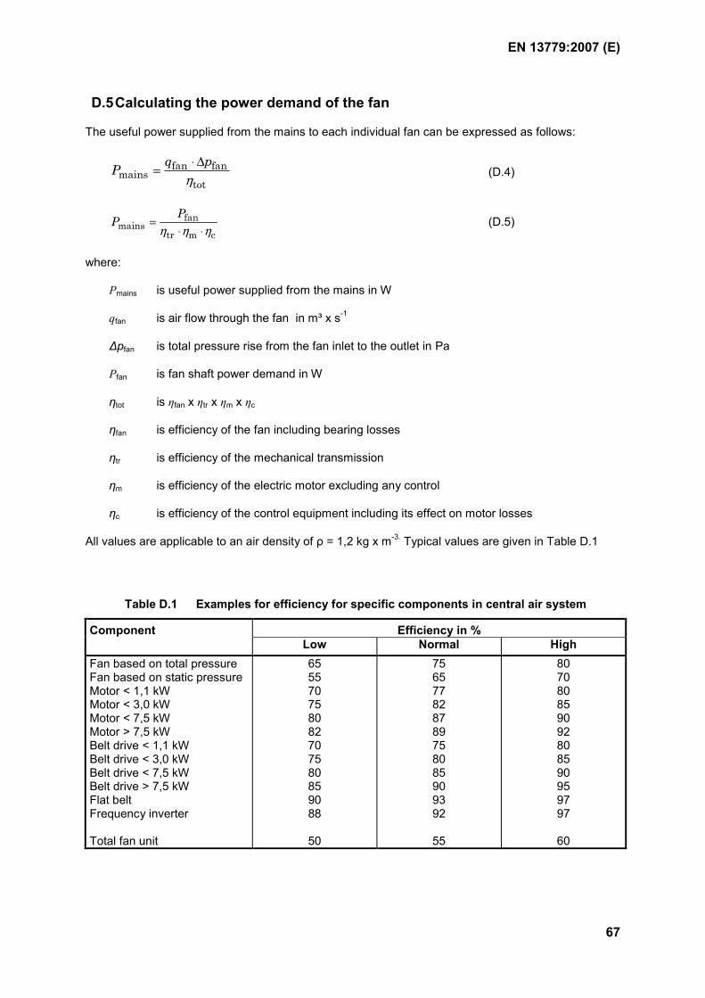
EN 13779:2007 (E)
67
D.5 Calculating the power demand of the fan
The useful power supplied from the mains to each individual fan can be expressed as follows:
fan fanmains
tot
q pPη⋅ ∆
= (D.4)
fanmains
tr m c
PPη η η
=⋅ ⋅
(D.5)
where:
Pmains is useful power supplied from the mains in W
qfan is air flow through the fan in m³ x s-1
∆pfan is total pressure rise from the fan inlet to the outlet in Pa
Pfan is fan shaft power demand in W
ηtot is ηfan x ηtr x ηm x ηc
ηfan is efficiency of the fan including bearing losses
ηtr is efficiency of the mechanical transmission
ηm is efficiency of the electric motor excluding any control
ηc is efficiency of the control equipment including its effect on motor losses
All values are applicable to an air density of ρ = 1,2 kg x m-3. Typical values are given in Table D.1
Table D.1 Examples for efficiency for specific components in central air system
Efficiency in % Component Low Normal High
Fan based on total pressure Fan based on static pressure Motor < 1,1 kW Motor < 3,0 kW Motor < 7,5 kW Motor > 7,5 kW Belt drive < 1,1 kW Belt drive < 3,0 kW Belt drive < 7,5 kW Belt drive > 7,5 kW Flat belt Frequency inverter Total fan unit
65 55 70 75 80 82 70 75 80 85 90 88
50
75 65 77 82 87 89 75 80 85 90 93 92
55
80 70 80 85 90 92 80 85 90 95 97 97
60
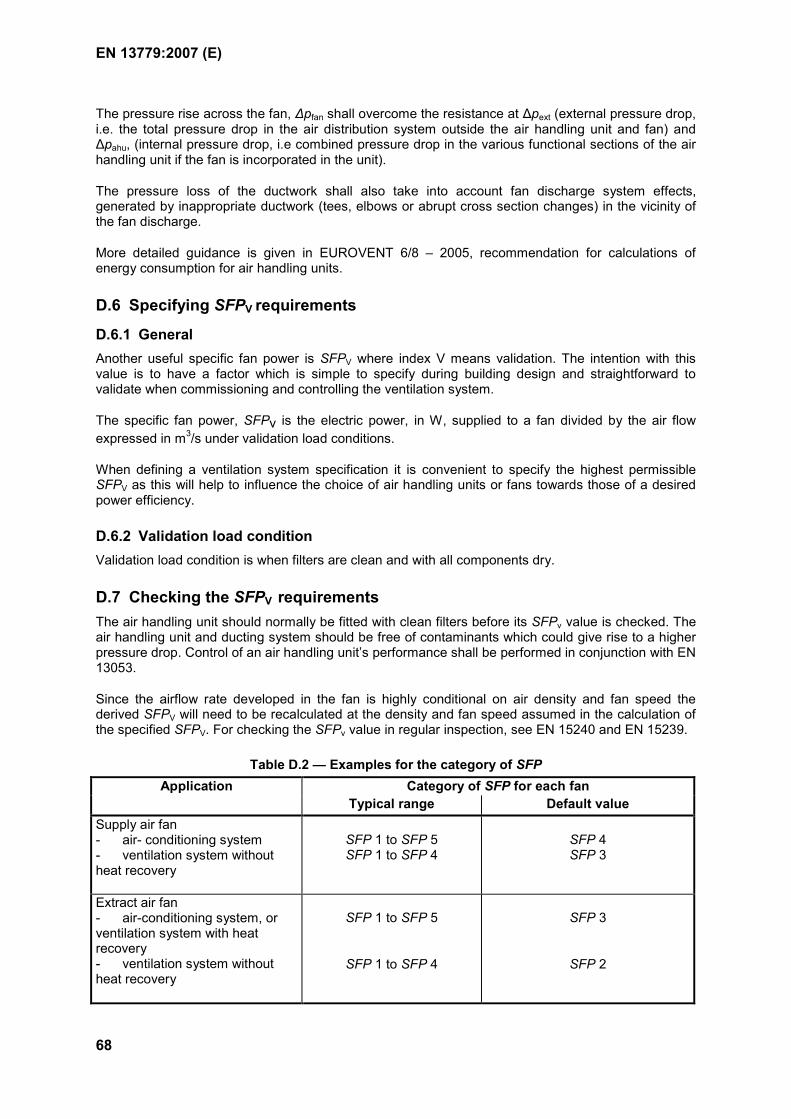
EN 13779:2007 (E)
68
The pressure rise across the fan, ∆pfan shall overcome the resistance at ∆pext (external pressure drop, i.e. the total pressure drop in the air distribution system outside the air handling unit and fan) and ∆pahu, (internal pressure drop, i.e combined pressure drop in the various functional sections of the air handling unit if the fan is incorporated in the unit).
The pressure loss of the ductwork shall also take into account fan discharge system effects, generated by inappropriate ductwork (tees, elbows or abrupt cross section changes) in the vicinity of the fan discharge.
More detailed guidance is given in EUROVENT 6/8 – 2005, recommendation for calculations of energy consumption for air handling units.
D.6 Specifying SFPV requirements
D.6.1 General Another useful specific fan power is SFPV where index V means validation. The intention with this value is to have a factor which is simple to specify during building design and straightforward to validate when commissioning and controlling the ventilation system.
The specific fan power, SFPv is the electric power, in W, supplied to a fan divided by the air flow expressed in m3/s under validation load conditions.
When defining a ventilation system specification it is convenient to specify the highest permissible SFPV as this will help to influence the choice of air handling units or fans towards those of a desired power efficiency.
D.6.2 Validation load condition Validation load condition is when filters are clean and with all components dry.
D.7 Checking the SFPV requirements The air handling unit should normally be fitted with clean filters before its SFPv value is checked. The air handling unit and ducting system should be free of contaminants which could give rise to a higher pressure drop. Control of an air handling unit’s performance shall be performed in conjunction with EN 13053.
Since the airflow rate developed in the fan is highly conditional on air density and fan speed the derived SFPV will need to be recalculated at the density and fan speed assumed in the calculation of the specified SFPV. For checking the SFPv value in regular inspection, see EN 15240 and EN 15239.
Table D.2 — Examples for the category of SFP Category of SFP for each fan Application
Typical range Default value Supply air fan - air- conditioning system - ventilation system without heat recovery
SFP 1 to SFP 5 SFP 1 to SFP 4
SFP 4 SFP 3
Extract air fan - air-conditioning system, or ventilation system with heat recovery - ventilation system without heat recovery
SFP 1 to SFP 5
SFP 1 to SFP 4
SFP 3
SFP 2
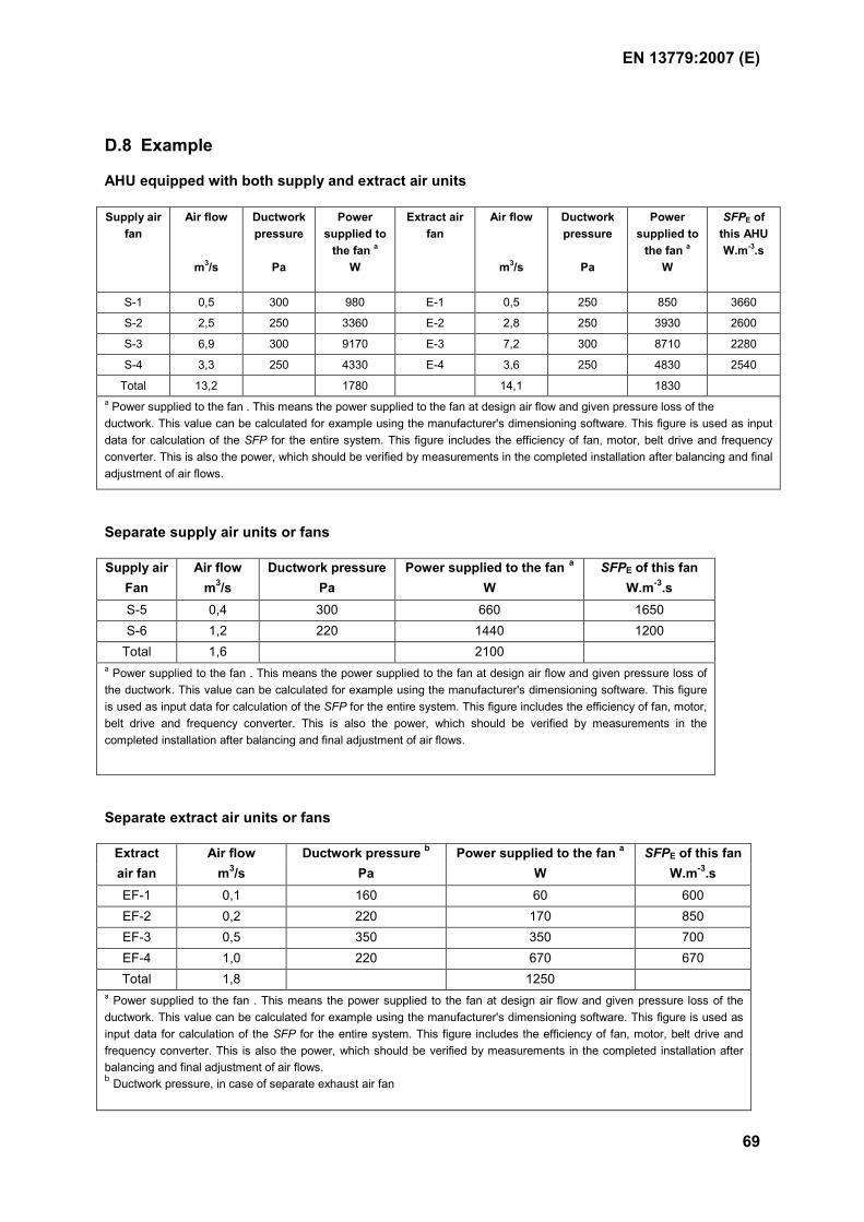
EN 13779:2007 (E)
69
D.8 Example
AHU equipped with both supply and extract air units
Supply air fan
Air flow
m3/s
Ductwork pressure
Pa
Power supplied to
the fan a W
Extract air fan
Air flow
m3/s
Ductwork pressure
Pa
Power supplied to
the fan a
W
SFPE of this AHU W.m-3.s
S-1 0,5 300 980 E-1 0,5 250 850 3660
S-2 2,5 250 3360 E-2 2,8 250 3930 2600
S-3 6,9 300 9170 E-3 7,2 300 8710 2280
S-4 3,3 250 4330 E-4 3,6 250 4830 2540
Total 13,2 1780 14,1 1830 a Power supplied to the fan . This means the power supplied to the fan at design air flow and given pressure loss of the ductwork. This value can be calculated for example using the manufacturer's dimensioning software. This figure is used as input data for calculation of the SFP for the entire system. This figure includes the efficiency of fan, motor, belt drive and frequency converter. This is also the power, which should be verified by measurements in the completed installation after balancing and final adjustment of air flows.
Separate supply air units or fans
Supply air Air flow Ductwork pressure Power supplied to the fan a SFPE of this fan Fan m3/s Pa W W.m-3.s
S-5 0,4 300 660 1650 S-6 1,2 220 1440 1200
Total 1,6 2100 a Power supplied to the fan . This means the power supplied to the fan at design air flow and given pressure loss of the ductwork. This value can be calculated for example using the manufacturer's dimensioning software. This figure is used as input data for calculation of the SFP for the entire system. This figure includes the efficiency of fan, motor, belt drive and frequency converter. This is also the power, which should be verified by measurements in the completed installation after balancing and final adjustment of air flows.
Separate extract air units or fans
Extract Air flow Ductwork pressure b Power supplied to the fan a SFPE of this fan air fan m3/s Pa W W.m-3.s
EF-1 0,1 160 60 600 EF-2 0,2 220 170 850 EF-3 0,5 350 350 700 EF-4 1,0 220 670 670 Total 1,8 1250
a Power supplied to the fan . This means the power supplied to the fan at design air flow and given pressure loss of the ductwork. This value can be calculated for example using the manufacturer's dimensioning software. This figure is used as input data for calculation of the SFP for the entire system. This figure includes the efficiency of fan, motor, belt drive and frequency converter. This is also the power, which should be verified by measurements in the completed installation after balancing and final adjustment of air flows. b Ductwork pressure, in case of separate exhaust air fan
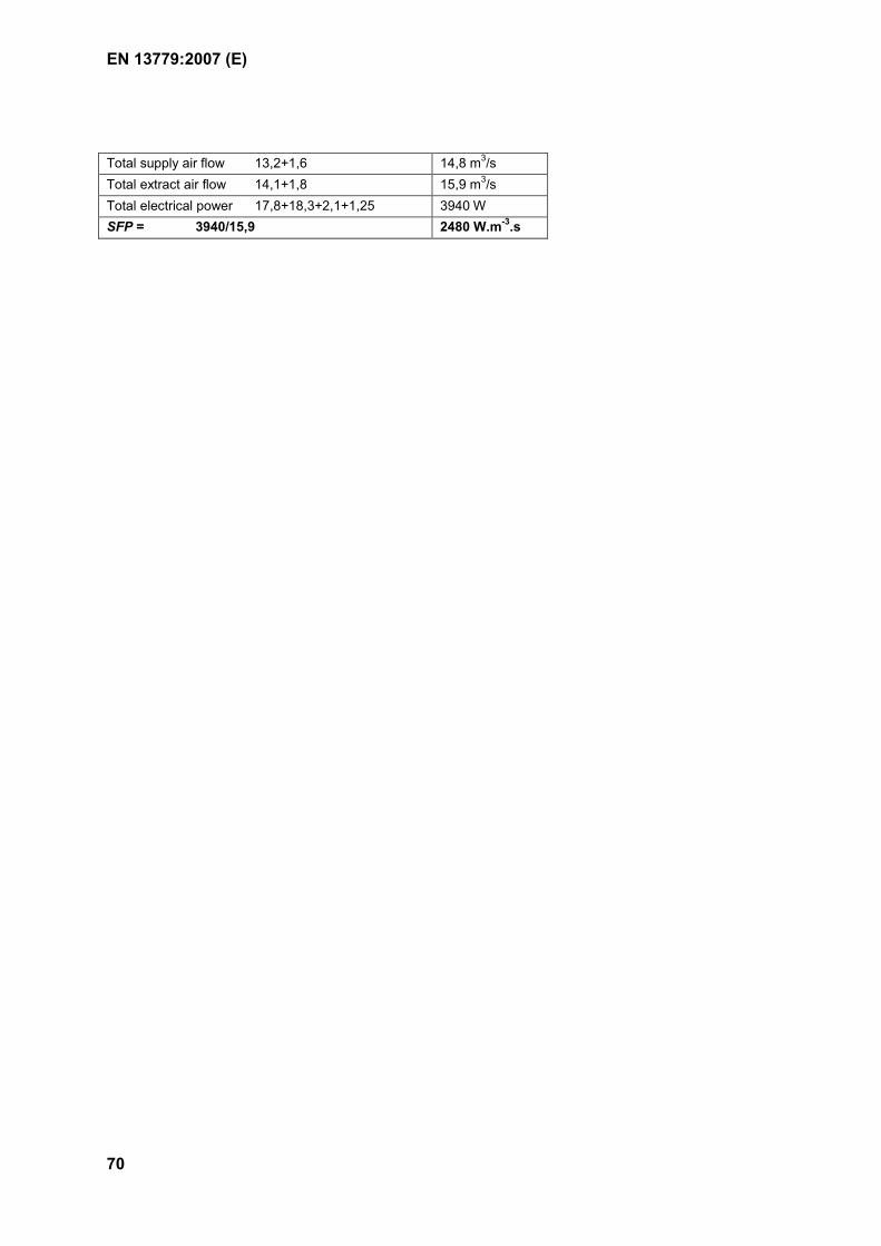
EN 13779:2007 (E)
70
Total supply air flow 13,2+1,6 14,8 m3/s Total extract air flow 14,1+1,8 15,9 m3/s Total electrical power 17,8+18,3+2,1+1,25 3940 W SFP = 3940/15,9 2480 W.m-3.s
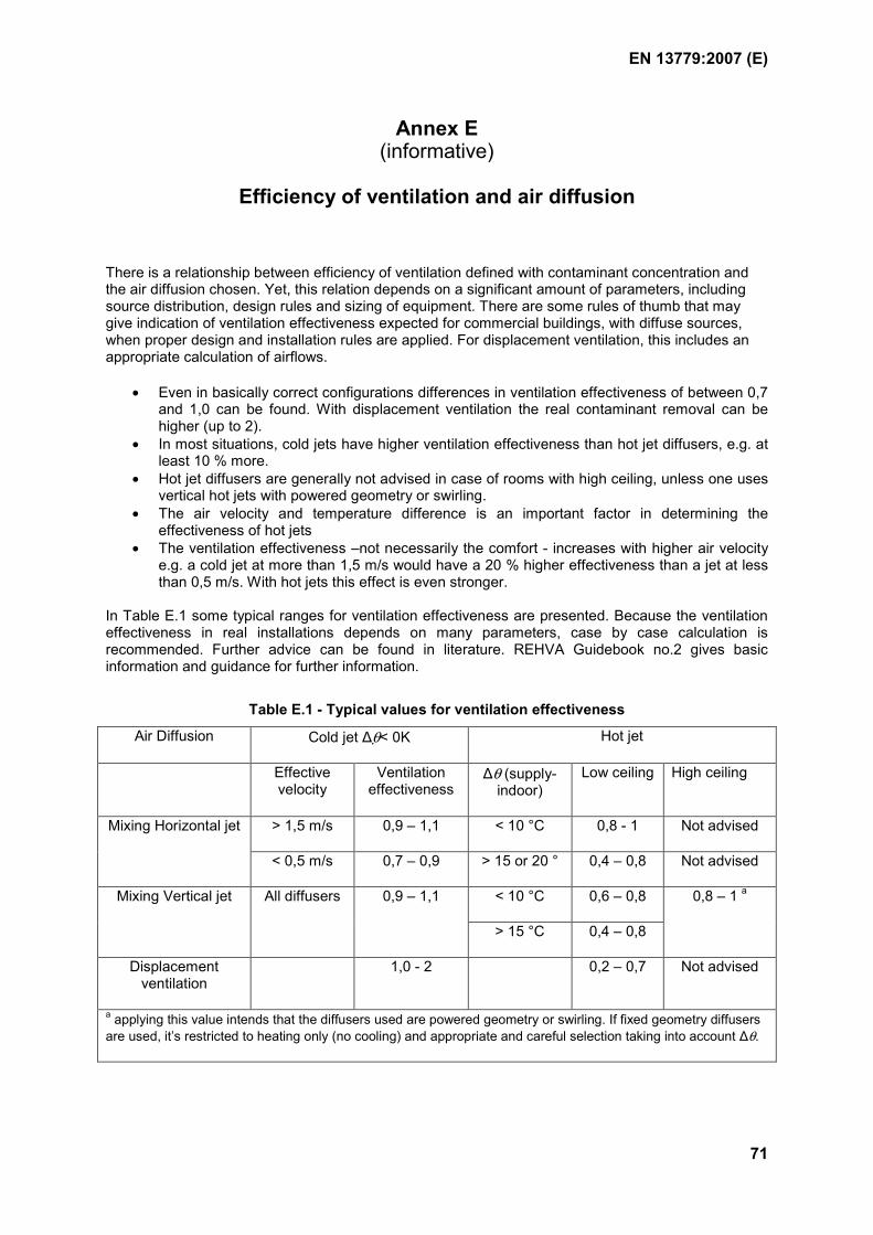
EN 13779:2007 (E)
71
Annex E (informative)
Efficiency of ventilation and air diffusion
There is a relationship between efficiency of ventilation defined with contaminant concentration and the air diffusion chosen. Yet, this relation depends on a significant amount of parameters, including source distribution, design rules and sizing of equipment. There are some rules of thumb that may give indication of ventilation effectiveness expected for commercial buildings, with diffuse sources, when proper design and installation rules are applied. For displacement ventilation, this includes an appropriate calculation of airflows.
• Even in basically correct configurations differences in ventilation effectiveness of between 0,7 and 1,0 can be found. With displacement ventilation the real contaminant removal can be higher (up to 2).
• In most situations, cold jets have higher ventilation effectiveness than hot jet diffusers, e.g. at least 10 % more.
• Hot jet diffusers are generally not advised in case of rooms with high ceiling, unless one uses vertical hot jets with powered geometry or swirling.
• The air velocity and temperature difference is an important factor in determining the effectiveness of hot jets
• The ventilation effectiveness –not necessarily the comfort - increases with higher air velocity e.g. a cold jet at more than 1,5 m/s would have a 20 % higher effectiveness than a jet at less than 0,5 m/s. With hot jets this effect is even stronger.
In Table E.1 some typical ranges for ventilation effectiveness are presented. Because the ventilation effectiveness in real installations depends on many parameters, case by case calculation is recommended. Further advice can be found in literature. REHVA Guidebook no.2 gives basic information and guidance for further information.
Table E.1 - Typical values for ventilation effectiveness
Air Diffusion Cold jet ∆θ< 0K Hot jet
Effective velocity
Ventilation effectiveness
∆θ (supply-indoor)
Low ceiling High ceiling
> 1,5 m/s 0,9 – 1,1 < 10 °C 0,8 - 1 Not advised Mixing Horizontal jet
< 0,5 m/s 0,7 – 0,9 > 15 or 20 ° 0,4 – 0,8 Not advised
< 10 °C 0,6 – 0,8 Mixing Vertical jet All diffusers 0,9 – 1,1
> 15 °C 0,4 – 0,8
0,8 – 1 a
Displacement ventilation
1,0 - 2 0,2 – 0,7 Not advised
a applying this value intends that the diffusers used are powered geometry or swirling. If fixed geometry diffusers are used, it’s restricted to heating only (no cooling) and appropriate and careful selection taking into account ∆θ.
EN 13779:2007 (E)
72
Bibliography
EN 779, Particulate air filters for general ventilation — Determination of the filtration performance
EN 1505, Ventilation for buildings — Sheet metal air ducts and fittings with rectangular cross section — Dimensions
EN 1506, Ventilation for buildings — Sheet metal air ducts and fittings with circular cross-section — Dimensions
EN 1507, Ventilation for buildings — Sheet metal air ducts with rectangular section — Requirements for strength and leakage
EN 1751 Ventilation for buildings — Air terminal devices - Aerodynamic testing of dampers and valves
EN 1886, Ventilation for buildings — Air handling units — Mechanical performance
EN 12237, Ventilation for buildings — Ductwork — Strength and leakage of circular sheet metal ducts
EN 12464-1, Light and lighting — Lighting of work places — Part 1: Indoor work places
EN 13030, Ventilation for buildings — Terminals — Performance testing of louvres subjected to simulated rain
EN 13829, Thermal performance of buildings — Determination of air permeability of buildings — Fan pressurisation method (ISO 9972:1996, modified)
CR 1752, Ventilation for buildings — Design criteria for the indoor environment
CEN/TR 14788, Ventilation for buildings — Design and dimensioning of residential ventilation systems
EN 15193 Energy performance of buildings - Energy requirements for lighting
prEN 15243:2005, Ventilation for buildings — Calculation of room temperatures and of load and energy for buildings with room conditioning systems
prEN 15459, Energy performance of buildings — Economic evaluation procedures related to energy systems in buildings, including renewable sources
EN ISO 7726, Ergonomics of the thermal environment — Instruments for measuring physical quantities (ISO 7726:1998)
ISO/DIS 16814, Building environmental design — Indoor air quality — Methods of expressing the quality of indoor air for human occupancy
Council Directive 99/30/EC of 22 April 1999 relating to limit values for sulphur dioxide, nitrogen dioxide and oxides of nitrogen, particulate matter and lead in ambient air
EUROVENT 6/8 recommendation for calculations of energy consumption for air handling units
World Health Organisation. Air Quality Guidelines for Europe, WHO, 1999
Mundt, E. et al, Ventilation effectiveness. REHVA Guidebook no.2.