Embed Size (px)
Citation preview
FE analysis and geometrical optimization of timber beech finger-jointunder bending test
Van-Dang Tran, Marc Oudjene n, Pierre-Jean MéausooneUniversité de Lorraine, Laboratoire d'Etudes et de Recherche sur le Matériau Bois (LERMAB), 27 Rue Philippe Séguin, 88026 Epinal, France
a r t i c l e i n f o
Article history:Accepted 19 March 2014Available online 4 April 2014
Keywords:Finger-jointGlued solid timberAdhesionAdhesiveCohesive behaviorFEMOptimization
a b s t r a c t
Experimental and numerical finite element results on the mechanical behavior of timber beech finger-joint are presented. Numerical simulations are based on the Cohesive Zone Model (CZM) of Abaqussoftware to allow for accurate description of the progressive damage of the bond-lines within the finger-joint up to failure. To increase the finger-joint resistance, the geometry of the finger-joint has beenoptimized using the Response Surface Method (RSM) and the Kriging interpolation. The finger length,the pitch and the tip gap have been defined as the design variables to optimize. The objective functionhas been defined in terms of the maximum bending force, obtained from four-point bending tests.Feasibility constraints on the design variables, conforming to the EN 14080 are also taken into account.The obtained results demonstrated clearly the potential in increasing the finger-joint resistance byoptimizing its geometry.
& 2014 Elsevier Ltd. All rights reserved.
1. Introduction
The research work reported herein is a part of a researchproject, undertaken at the LERMAB laboratory of the University ofLorraine, which was devoted to the study of adhesively bondedsolid beech timber beams for structural purposes. The experi-mental program of the project includes mechanical characteriza-tion of beech timber on small samples and full-scale destructivebending tests according to the EN 408 [1] to evaluate the modulusof elasticity (MOE) and the modulus of rupture (MOR) of gluedbeech beams. Two-layer and three-layer glued beams with orwithout finger-joints have been constructed from laminationshaving 42 mm thickness. Finger profiling was performed byprofiling cutterheads with the following characteristics: 22 mmfinger length, 6 mm pitch and 1 mm tip gap. The adopted finger-joint geometry meets the requirements of the EN 14080 [2]. Theadhesive used to glue laminations and finger-joints was mela-mine–urea–formaldehyde (MUF) that fulfils current approvalcriteria for the use in load-bearing timber components.
Preliminary results from full-scale destructive bending testsshowed that glued-solid timber beams without finger-jointsbehave better and present greater MOR than glued-solid timberbeams with finger-joints. Inspection of failure modes revealedthat all beams having finger-joints in the zone with maximumbending moment (tension zone) showed premature failure, which
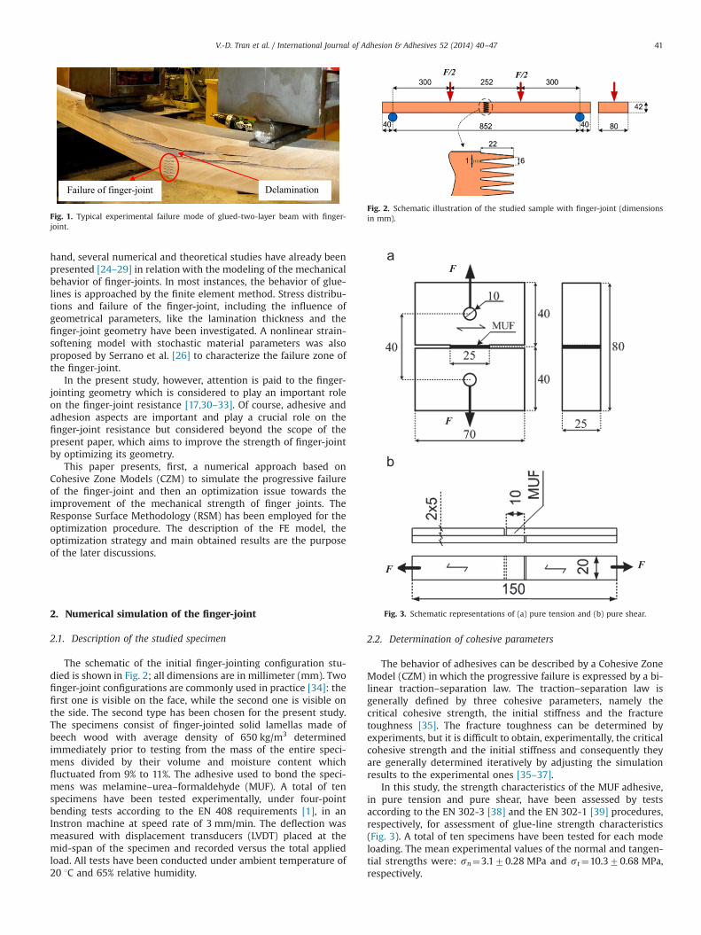
propagates by steps: it takes place, first, at the finger-joint andthen propagates to the inter-layer bond-line (Fig. 1). Thus, the fullrupture of the specimen is characterized by a cascading brittlecrack pattern combining finger-joint rupture and inter-layer dela-mination. Therefore, it can be concluded that the actual finger-joints are the weak links of glued-solid beech timber beams.
Performance of finger-joints, with different wood species, hasbeen extensively studied in the literature, where it has beenshown that the finger-joint strength depends on several inter-linked factors related to the gluing process, namely glue spreadrate, assembly time and the pressure applied [3]. Also, specificgravity of wood, planning and lamella thickness affect the finger-joint resistance [3]. Other studies, by many authors, have focussedon the bond-lines formation and stability. Collett [4] and Wake [5]have studied the influence of the chemistry of adhesives and thewetting of wood on the bond-lines formation and stability. Theinfluence of surface roughness and weak boundary layer formationhas been investigated by Stehr et al. [6–8]. Also the penetration ofadhesives into cell cavities and the diffusion of the adhesive intothe cell wall of the wood have been found to significantlyinfluence the strength of finger-joints [9–13]. Cheng and Sun[14] have reported that low viscosity adhesives penetrated moreinto the substrate creating a poor adhesive–substrate interface,which in turn resulted in lower bonding strength. The strength offinger-joints bonded with different types of adhesives has alsoreceived attention [15–19] at ambient temperature or at elevatedtemperature [20,21]. Schmidt et al. [22], and Aicher and Reinhardt[23] have studied the curing process of MUF adhesives which isconsidered to affect the bond strength and formation. On the other
Contents lists available at ScienceDirect
journal homepage: www.elsevier.com/locate/ijadhadh
International Journal of Adhesion & Adhesives
http://dx.doi.org/10.1016/j.ijadhadh.2014.03.0070143-7496/& 2014 Elsevier Ltd. All rights reserved.
n Corresponding author. Tel.: þ33 3 29 29 61 37; fax: þ33 3 29 29 61 38.E-mail address: [email protected] (M. Oudjene).
International Journal of Adhesion & Adhesives 52 (2014) 40–47
hand, several numerical and theoretical studies have already beenpresented [24–29] in relation with the modeling of the mechanicalbehavior of finger-joints. In most instances, the behavior of glue-lines is approached by the finite element method. Stress distribu-tions and failure of the finger-joint, including the influence ofgeometrical parameters, like the lamination thickness and thefinger-joint geometry have been investigated. A nonlinear strain-softening model with stochastic material parameters was alsoproposed by Serrano et al. [26] to characterize the failure zone ofthe finger-joint.
In the present study, however, attention is paid to the finger-jointing geometry which is considered to play an important roleon the finger-joint resistance [17,30–33]. Of course, adhesive andadhesion aspects are important and play a crucial role on thefinger-joint resistance but considered beyond the scope of thepresent paper, which aims to improve the strength of finger-jointby optimizing its geometry.
This paper presents, first, a numerical approach based onCohesive Zone Models (CZM) to simulate the progressive failureof the finger-joint and then an optimization issue towards theimprovement of the mechanical strength of finger joints. TheResponse Surface Methodology (RSM) has been employed for theoptimization procedure. The description of the FE model, theoptimization strategy and main obtained results are the purposeof the later discussions.
2. Numerical simulation of the finger-joint
2.1. Description of the studied specimen
The schematic of the initial finger-jointing configuration stu-died is shown in Fig. 2; all dimensions are in millimeter (mm). Twofinger-joint configurations are commonly used in practice [34]: thefirst one is visible on the face, while the second one is visible onthe side. The second type has been chosen for the present study.The specimens consist of finger-jointed solid lamellas made ofbeech wood with average density of 650 kg/m3 determinedimmediately prior to testing from the mass of the entire speci-mens divided by their volume and moisture content whichfluctuated from 9% to 11%. The adhesive used to bond the speci-mens was melamine–urea–formaldehyde (MUF). A total of tenspecimens have been tested experimentally, under four-pointbending tests according to the EN 408 requirements [1], in anInstron machine at speed rate of 3 mm/min. The deflection wasmeasured with displacement transducers (LVDT) placed at themid-span of the specimen and recorded versus the total appliedload. All tests have been conducted under ambient temperature of20 1C and 65% relative humidity.
2.2. Determination of cohesive parameters
The behavior of adhesives can be described by a Cohesive ZoneModel (CZM) in which the progressive failure is expressed by a bi-linear traction–separation law. The traction–separation law isgenerally defined by three cohesive parameters, namely thecritical cohesive strength, the initial stiffness and the fracturetoughness [35]. The fracture toughness can be determined byexperiments, but it is difficult to obtain, experimentally, the criticalcohesive strength and the initial stiffness and consequently theyare generally determined iteratively by adjusting the simulationresults to the experimental ones [35–37].
In this study, the strength characteristics of the MUF adhesive,in pure tension and pure shear, have been assessed by testsaccording to the EN 302-3 [38] and the EN 302-1 [39] procedures,respectively, for assessment of glue-line strength characteristics(Fig. 3). A total of ten specimens have been tested for each modeloading. The mean experimental values of the normal and tangen-tial strengths were: sn¼3.170.28 MPa and st¼10.370.68 MPa,respectively.
Failure of finger-joint Delamination
Fig. 1. Typical experimental failure mode of glued-two-layer beam with finger-joint.
F/2 F/2
Fig. 2. Schematic illustration of the studied sample with finger-joint (dimensionsin mm).
F F
F
F
Fig. 3. Schematic representations of (a) pure tension and (b) pure shear.
V.-D. Tran et al. / International Journal of Adhesion & Adhesives 52 (2014) 40–47 41
By referring to the notation used for the ABAQUS traction–separation law, the cohesive parameters are: the critical cohesivestrengths ðsc
n; sct Þ, the initial stiffness ðKn; KtÞ and the maximum
displacements ðδmaxn ; δmax
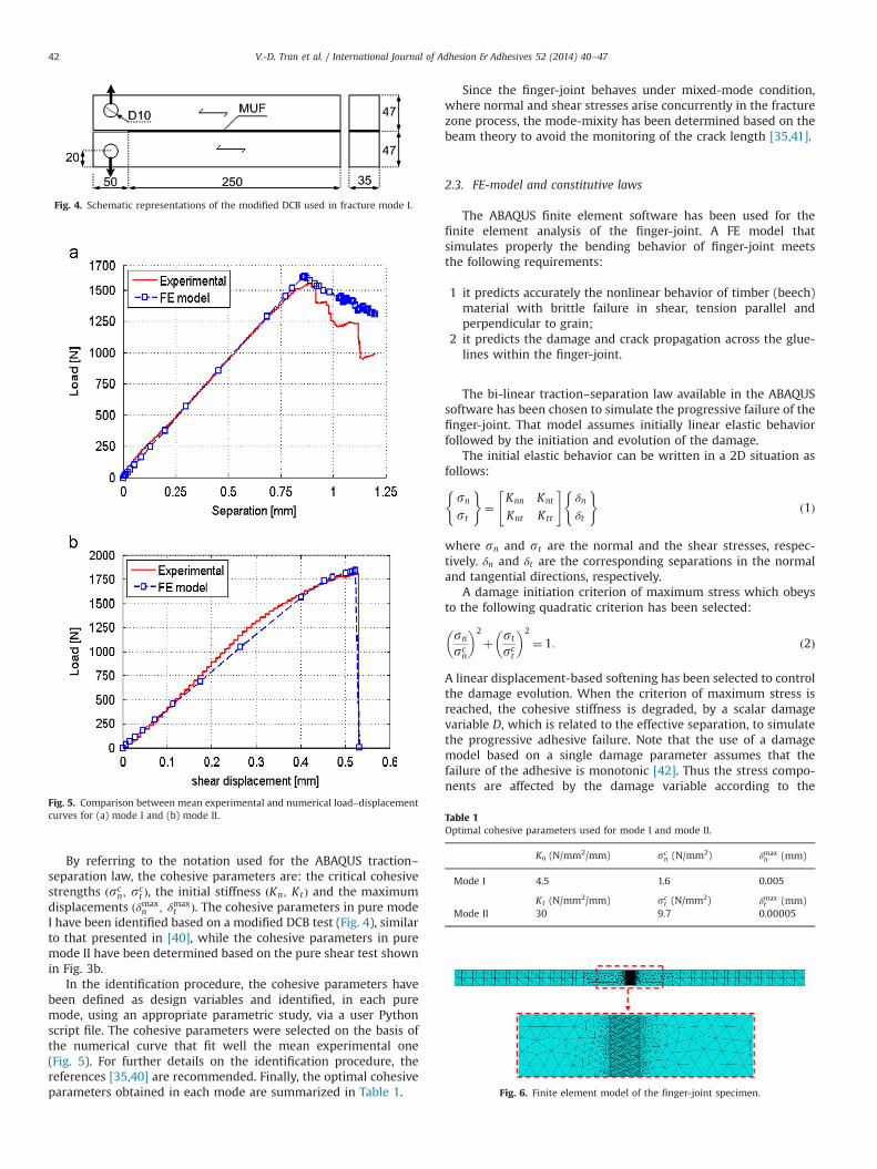
t Þ. The cohesive parameters in pure modeI have been identified based on a modified DCB test (Fig. 4), similarto that presented in [40], while the cohesive parameters in puremode II have been determined based on the pure shear test shownin Fig. 3b.
In the identification procedure, the cohesive parameters havebeen defined as design variables and identified, in each puremode, using an appropriate parametric study, via a user Pythonscript file. The cohesive parameters were selected on the basis ofthe numerical curve that fit well the mean experimental one(Fig. 5). For further details on the identification procedure, thereferences [35,40] are recommended. Finally, the optimal cohesiveparameters obtained in each mode are summarized in Table 1.
Since the finger-joint behaves under mixed-mode condition,where normal and shear stresses arise concurrently in the fracturezone process, the mode-mixity has been determined based on thebeam theory to avoid the monitoring of the crack length [35,41].
2.3. FE-model and constitutive laws
The ABAQUS finite element software has been used for thefinite element analysis of the finger-joint. A FE model thatsimulates properly the bending behavior of finger-joint meetsthe following requirements:
1 it predicts accurately the nonlinear behavior of timber (beech)material with brittle failure in shear, tension parallel andperpendicular to grain;
2 it predicts the damage and crack propagation across the glue-lines within the finger-joint.
The bi-linear traction–separation law available in the ABAQUSsoftware has been chosen to simulate the progressive failure of thefinger-joint. That model assumes initially linear elastic behaviorfollowed by the initiation and evolution of the damage.
The initial elastic behavior can be written in a 2D situation asfollows:
sn
st
( )¼
Knn Knt
Knt Ktt
" #δn
δt
( )ð1Þ
where sn and st are the normal and the shear stresses, respec-tively. δn and δt are the corresponding separations in the normaland tangential directions, respectively.
A damage initiation criterion of maximum stress which obeysto the following quadratic criterion has been selected:
sn
scn
� �2
þ st
sct
� �2
¼ 1: ð2Þ
A linear displacement-based softening has been selected to controlthe damage evolution. When the criterion of maximum stress isreached, the cohesive stiffness is degraded, by a scalar damagevariable D, which is related to the effective separation, to simulatethe progressive adhesive failure. Note that the use of a damagemodel based on a single damage parameter assumes that thefailure of the adhesive is monotonic [42]. Thus the stress compo-nents are affected by the damage variable according to the
Fig. 4. Schematic representations of the modified DCB used in fracture mode I.
Fig. 5. Comparison between mean experimental and numerical load–displacementcurves for (a) mode I and (b) mode II. Table 1
Optimal cohesive parameters used for mode I and mode II.
Kn (N/mm2/mm) scn (N/mm2) δmax
n (mm)
Mode I 4.5 1.6 0.005
Kt (N/mm2/mm) sct (N/mm2) δmax
t (mm)Mode II 30 9.7 0.00005
Fig. 6. Finite element model of the finger-joint specimen.
V.-D. Tran et al. / International Journal of Adhesion & Adhesives 52 (2014) 40–4742
following:
sn ¼ð1�DÞsn; snZ0sn; snr0
(ð3Þ
st ¼ ð1�DÞst ð4Þ
where sn and st are the normal and tangential stress componentscomputed by the elastic traction–separation law for the currentseparations without damage, respectively.
The damage parameter D, for linear softening, is based on theeffective displacement δm ¼
ffiffiffiffiffiffiffiffiffiffiffiffiffiffiffiffiffiffiffi⟨δn⟩2þδ2t
q(in the 2D situation) used
for general cases of damage under mixed-mode combining normaland shear stresses and can be expressed as follows [42]:
D¼ δfmðδmaxm �δ0mÞ
δmaxm ðδfm�δ0mÞ
ð5Þ
where δ0m and δfm are the effective displacements at initial damageand complete failure, respectively.
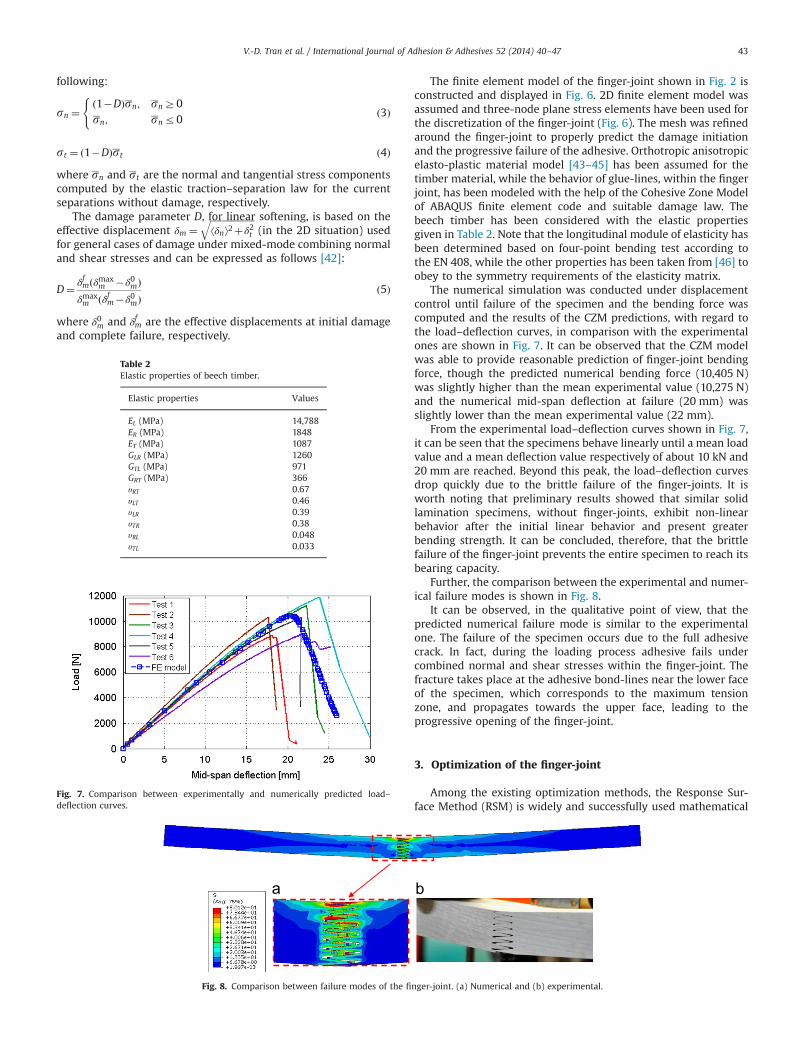
The finite element model of the finger-joint shown in Fig. 2 isconstructed and displayed in Fig. 6. 2D finite element model wasassumed and three-node plane stress elements have been used forthe discretization of the finger-joint (Fig. 6). The mesh was refinedaround the finger-joint to properly predict the damage initiationand the progressive failure of the adhesive. Orthotropic anisotropicelasto-plastic material model [43–45] has been assumed for thetimber material, while the behavior of glue-lines, within the fingerjoint, has been modeled with the help of the Cohesive Zone Modelof ABAQUS finite element code and suitable damage law. Thebeech timber has been considered with the elastic propertiesgiven in Table 2. Note that the longitudinal module of elasticity hasbeen determined based on four-point bending test according tothe EN 408, while the other properties has been taken from [46] toobey to the symmetry requirements of the elasticity matrix.
The numerical simulation was conducted under displacementcontrol until failure of the specimen and the bending force wascomputed and the results of the CZM predictions, with regard tothe load–deflection curves, in comparison with the experimentalones are shown in Fig. 7. It can be observed that the CZM modelwas able to provide reasonable prediction of finger-joint bendingforce, though the predicted numerical bending force (10,405 N)was slightly higher than the mean experimental value (10,275 N)and the numerical mid-span deflection at failure (20 mm) wasslightly lower than the mean experimental value (22 mm).
From the experimental load–deflection curves shown in Fig. 7,it can be seen that the specimens behave linearly until a mean loadvalue and a mean deflection value respectively of about 10 kN and20 mm are reached. Beyond this peak, the load–deflection curvesdrop quickly due to the brittle failure of the finger-joints. It isworth noting that preliminary results showed that similar solidlamination specimens, without finger-joints, exhibit non-linearbehavior after the initial linear behavior and present greaterbending strength. It can be concluded, therefore, that the brittlefailure of the finger-joint prevents the entire specimen to reach itsbearing capacity.
Further, the comparison between the experimental and numer-ical failure modes is shown in Fig. 8.
It can be observed, in the qualitative point of view, that thepredicted numerical failure mode is similar to the experimentalone. The failure of the specimen occurs due to the full adhesivecrack. In fact, during the loading process adhesive fails undercombined normal and shear stresses within the finger-joint. Thefracture takes place at the adhesive bond-lines near the lower faceof the specimen, which corresponds to the maximum tensionzone, and propagates towards the upper face, leading to theprogressive opening of the finger-joint.
3. Optimization of the finger-joint
Among the existing optimization methods, the Response Sur-face Method (RSM) is widely and successfully used mathematical
Table 2Elastic properties of beech timber.
Elastic properties Values
EL (MPa) 14,788ER (MPa) 1848ET (MPa) 1087GLR (MPa) 1260GTL (MPa) 971GRT (MPa) 366υRT 0.67υLT 0.46υLR 0.39υTR 0.38υRL 0.048υTL 0.033
Fig. 7. Comparison between experimentally and numerically predicted load–deflection curves.
Fig. 8. Comparison between failure modes of the finger-joint. (a) Numerical and (b) experimental.
V.-D. Tran et al. / International Journal of Adhesion & Adhesives 52 (2014) 40–47 43
tool for optimization problems in many fields of structuralmechanics. It is based generally on statistical considerations inorder to build local approximations of the real unknown functionto be optimized. It uses the Design of Experiments (DoE) methodto build approximated response surfaces. The DoE method isused to evaluate effectively the response of a system which isinfluenced by the variation of the design variables. To properlyformulate an optimization problem, it is necessary to understandthe characteristics of the system and to define precisely the designvariables affecting the response of the system.
3.1. Formulation of the optimization problem
To increase the resistance of finger-joints, the optimizationproblem is expressed as follows:
max JðxÞ�subjected to xurxrxv ð5Þ
where JðxÞ is the objective function, xu and xv are the lower and theupper bound vectors of the design variable x, respectively.
The optimization problem consists in determining the optimalgeometry to achieve a higher resistance of finger-joints, whichcorresponds to the maximum value of the cost (or objective)function J. Therefore, the finger length, the pitch and tip gap,denoted A, B, and C, respectively were defined as the designvariables which affect the failure behavior of the finger-joint. Thecost function J to maximize is related to the maximum bendingforce Fmax which can be expressed under its normalized form asfollows:
J ¼ Fmax
F0ð6Þ
where F0 is the maximum bending force of the finger-jointcomputed with the initial geometry.
Feasibility constraints on the geometrical parameters are alsoconsidered, leading to a bounded design variables. In the presentstudy, the lower and upper bounds were chosen according to theEN 14080 [1] requirements regarding the profiling of finger-joints,but can be defined otherwise. Thus, the feasibility constraints areexpressed as follows:
ðxÞ :xu1rx1 ¼ Arxv1xu2rx2 ¼ Brxv2xu3rx3 ¼ Crxv3
8><>: ð7Þ
After defining the design variables, the levels and the numberof experiments were determined by using the central compositeDesign of Experiments (DoE).
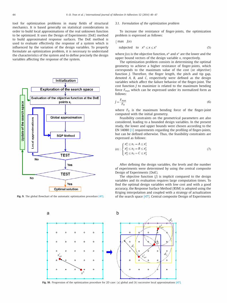
The objective function (J) is implicit compared to the designvariables and its evaluation requires large computation times. Tofind the optimal design variables with low cost and with a goodaccuracy, the Response Surface Method (RSM) is adopted using theKriging interpolation and coupled with a strategy of actualizationof the search space [47]. Central composite Design of ExperimentsFig. 9. The global flowchart of the automatic optimization procedure [47].
0x
1optx
2optx
1optx
koptx
2d
1d
kd
Fig. 10. Progression of the optimization procedure for 2D case: (a) global and (b) successive local approximations [47].
V.-D. Tran et al. / International Journal of Adhesion & Adhesives 52 (2014) 40–4744
(DoE) with five levels for function evaluation has been adopted tobuild the response surfaces.
3.2. The Kriging interpolation
The Kriging [47,48] interpolation method is a powerful inter-polation technique which is widely used in optimization problems.It enables to represent complicated functions. This method isapplied in this work to represent the response surface in anexplicit form, according to design variables. Only a brief descrip-tion of the Kriging model is given here, for further detailsreference is made to [47–49]. The approximate relationship ofthe objective and constraint function can be expressed as follows:
JnðxÞ ¼ PT ðxÞβþrT ðxÞα ð8Þwhere β¼ ½β1; :::::::::; βm�T is the coefficient vector and the randomfluctuation. rT ðxÞα is an interpolation of the residuals of theregression model, while PT ðxÞβ is used to represent the deviationof the global model.
3.3. The optimization procedure
The goal of RSM is to decrease the cost of functions evaluationin structural optimization. The strategies adopted in this workallow to build precise approximations in order to find an accurateglobal optimum. In this paper, we limit ourselves to a shortpresentation of the optimization strategy.
The general overview of the above procedure is shown in Fig. 9.First, a global approximation is made initially by considering aweight function which is equal to zero (a global approximation),and in order to avoid a local optimum successive optimizations areperformed automatically using the SQP algorithm to obtain thebest optimal solution starting from each point of the DoE. Thebest solution among those obtained in various optimizations isthen considered (Fig. 10a). After that, successive local approxima-tions are built in the vicinity of the optima (Fig. 10b) to obtain amore accurate approximation of the optimization problem locally(centered around the best minimum). The iterative procedurestops when the successive optima of the approximate functionbecome close. Finally, another evaluation is carried out to obtainthe real response.
During the progression of the optimization procedure, theregion of interest moves and zooms on each optimum by reducingthe search space by 1/3.
In addition, evaluation points which have been already calcu-lated are duly taken into account when working on a new searchspace. The optimization procedure is stopped when the size of thesearch space becomes too small or when the successive optimabecome close.
A Python Script is used to create the ABAQUS finite elementmodel, to run the computations and to post-process the results,which are exported in an ASCII file. That file is then read by aFORTRAN program, in which the response surface approximationsand SQP algorithm are implemented.
4. Optimization results
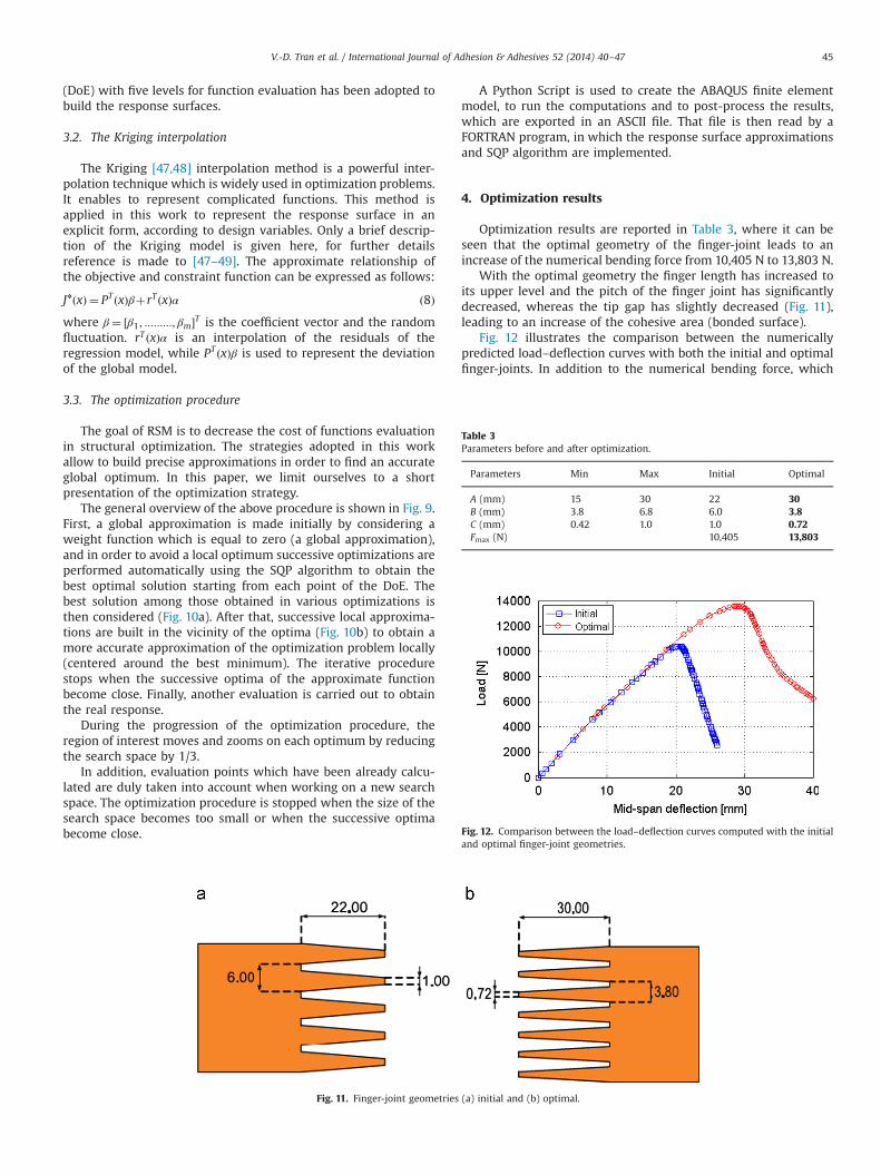
Optimization results are reported in Table 3, where it can beseen that the optimal geometry of the finger-joint leads to anincrease of the numerical bending force from 10,405 N to 13,803 N.
With the optimal geometry the finger length has increased toits upper level and the pitch of the finger joint has significantlydecreased, whereas the tip gap has slightly decreased (Fig. 11),leading to an increase of the cohesive area (bonded surface).
Fig. 12 illustrates the comparison between the numericallypredicted load–deflection curves with both the initial and optimalfinger-joints. In addition to the numerical bending force, which
Table 3Parameters before and after optimization.
Parameters Min Max Initial Optimal
A (mm) 15 30 22 30B (mm) 3.8 6.8 6.0 3.8C (mm) 0.42 1.0 1.0 0.72Fmax (N) 10,405 13,803
Fig. 11. Finger-joint geometries (a) initial and (b) optimal.
Fig. 12. Comparison between the load–deflection curves computed with the initialand optimal finger-joint geometries.
V.-D. Tran et al. / International Journal of Adhesion & Adhesives 52 (2014) 40–47 45
increased from 10,405 N to 13,803 N, it can be also seen from thisfigure that the deflection at failure has been increased from about20 mm to 29 mm.
5. Conclusion
The aim of this paper was to optimize the finger-jointinggeometry towards the improvement of its mechanical strength.The crack growth across the bond-lines of the finger-joint has beensuccessfully modeled using the cohesive surfaces of ABAQUS andsuitable damage laws. This computational approach was found tobe suitable for cracked bond-lines where the crack propagatesthrough a known direction. In this study, finger-joints have beenidentified as the weakest points of the entire jointed specimens.Thus, an improvement of the finger-joint resistance is proposedbased on the optimization of its geometry. The Response SurfaceMethod (RSM) has been used for the optimization purpose.Response surfaces were built using the Kriging interpolation. Theobjective function has been defined in terms of the maximumbending force, obtained from four-point bending tests.
Feasibility constraints on the geometrical parameters are alsotaken into account. In order to improve the RSM accuracy and todeal with the local optimum problem, an efficient optimizationstrategy allowing the actualization of the search space has beenadopted.
The obtained numerical results demonstrated clearly thepotential of increasing the finger-joint resistance by optimizingits geometry.
Acknowledgment
The authors would like to thank Dr. N. Lebaal for the fruitfuldiscussions and his help regarding the optimization strategy. Also,the financial support of the French Ministry of High Education andResearch (MESR-2011) is gratefully acknowledged "Terres deHêtre" is gratefully acknowledged for providing beech timber usedin the experiments.
References
[1] EN 408. Timber structures – structural timber and glued-laminated timber –
determination of some physical and mechanical properties. Bruxelles; Novem-ber 2010.
[2] EN 14080. Timber structures – glued laminated timber and glued solid timber– requirements. 2012.
[3] Bourreau D, Aimene Y, Beauchêne J, Thibaut B. Feasibility of glued laminatedtimber beams with tropical hardwoods. Eur J Wood Wood Prod2013;71:653–62.
[4] Collett BM. A review of surface and interfacial adhesion in wood science andrelated fields. Wood Sci Technol 1972;6:1–42.
[5] Wake WC. Adhesion and formulation of adhesives. London: Applied SciencePublishers; 1976.
[6] Stehr M, Sltman J, Johansson I. Laser ablation of machined wood surfaces. 1.Effect on end-grain gluing of pine (Pinus silvestris L.) and spruce (Picea abiesKarst.). Holzforschung 1999;53(1):93–103.
[7] Stehr M. Laser ablation of machined wood surfaces. 2. Effect on end-graingluing of pine (Pinus silvestris L.). Holzforschung 1999;53(6):655–61.
[8] Stehr M, Johansson I. Weak boundary layers on wood surfaces. J Adhes SciTechnol 2000;14:1211–24.
[9] Frazier CE, Ni J. On the occurence of network interpenetration in the wood-isocyanate adhesive interphase. Int J Adhes Adhes 1998;18:81–7.
[10] Sernek M, Resnik J, Kamke FA. Penetration of a liquid urea–formaldehydeadhesive into beech wood. Wood Fiber Sci 1999;31:41–8.
[11] Buckley CJ, Phanopoulos C, Khaleque N, engelen A, Holwill MEJ, Michette AG.Examination of the penetration of polymeric methylene di-phenyl-di-isocyanate (pMDI) into wood structure using chemical state x-ray microscopy.Holzforschung 2002;56:215–22.
[12] Gindl W, Dessipri E, Wimmer R. Using UV microscopy to study diffusion ofmelamine-urea-formaldehyde resin in cell walls of spruce wood. Holz-forschung 2002;56:103–7.
[13] Smith MJ, Dai H, Ramani K. Wood thermoplastic adhesive interface – methodof characterization and results. Int J Adhes Adhes 2002;22:197–204.
[14] Cheng E, Sun X. Effects of wood surface roughness, adhesive viscosity andprocessing pressure on adhesion strength of protein adhesive. J Adhes SciTechnol 2006;20:997–1017.
[15] Konnerth J, Gindl W, Müller U. Elastic properties of adhesive polymers. Part I:polymer films by means of electronic speckle pattern interferometry. J ApplPolym Sci 2014 2007; 103(6): 3936–9.
[16] Liu CT, Lii WJ. Effect of physicochemical properties and gluing methods on thequalities laminated wood made from fast-growing species. 9. Studies on thefabrication of end-to-end grain joint laminated wood from Taiwan acacia,sweet gum and Taiwania. For Prod Ind 1989;8:75–84.
[17] Karastergiou S, Barboutis J, Vassiliou V. Effect of the PVA gluing on bendingstrength properties of finger jointed turkey oakwood (Quercus cerris L.). HolzRoh Werkst 2006;64:339–40.
[18] Frangi A, Fontana M, Mischler A. Shear behaviour of bond lines in gluedlaminated timber beams at high temperature. Wood Sci Technol2004;38:119–26.
[19] Gonzalez G, Moya R, Monge F, Cordoba R, Coto JC. Evaluating the strengthof finger jointed lumbers of Gmelina Arborea in Costa Rica 2004;28:319–-23New For 2004;28:319–23.
[20] Frangi A, Bertocchi M, Clauß S, Niemz P. Mechanical behaviour of finger jointsat elevated temperatures. Wood Sci Technol 2012;46:793–812.
[21] Clauß S, Joscak M, Niemz P. Thermal stability of glued wood joints measuredby shear tests. Eur J Wood Prod 2011;69(1):101–11.
[22] Schmidt M, Thon̈nißen A, Knorz M, Windeisen E, Wegener G. Relevant woodcharacteristics for gluing beech and ash with regard to discoloration. Eur JWood Wood Prod 2012;70:319–25.
[23] Aicher A, Reinhardt HW. Delaminierungseigenschaften und scherfestigkeitenvon verklebten rotkernigen buchenholz-lamellen. Holz Roh Werkst2007;65:125–36.
[24] Aicher S, Radovic B. Untersuchungen zum Einflußder Keilzinkengeometrie aufdie Zugfestigkeit keilgezinkter Brettschichtholz-Lamellen. Holz Roh Werkst1999;57:1–11.
[25] Smardzewski J. Distribution of stresses in finger joints. Wood Sci Technol1996;30:477–89.
[26] Serrano E, Gustafsson PJ, Larsen HJ. Modelling of finger-joint failure in glued-laminated timber beams. J Struct Eng ASCE 2001;127(8):914–21.
[27] Wernersson H. Fracture characterization of wood adhesive joints. ReportTVSM-1006. Lund University, Division of Structural Mechanics: Lund, Sweden;1974.
[28] Serrano E, Gustafsson PJ. Influence of bondline brittleness and defects on thestrength of timber finger-joints. Int J Adhes Adhes 1999;19(1):9–17.
[29] Milner HR, Yeoh E. Finite element analysis of glued timber finger joints. JStruct Eng 1991;117(3):755–66.
[30] Yeh MC, Lin YL. Finger joint performance of structural laminated bamboomember. J Wood Sci 2012;58:120–7.
[31] Ratnasingam J, Scholz F. Optimization of finger-jointing in rubber woodprocessing. Eur J Wood Wood Prod 2009;67:241–2.
[32] Walford BG. Effect of finger length on finger-joint strength in radiate pine. In:Proceedings of the 6th world conference on timber engineering. 2000.
[33] Rao S, Gong M, Chui YH, Mohammad M. Effect of geometric parameters offinger joint profile on ultimate tensile strength of single finger-jointed boards.Wood Fiber Sci 2012;4:263–70.
[34] EN 385. Aboutages à entures multiples dans le bois de construction –
Exigences de performance et exigencies minimales de fabrication. mars 2002.[35] Lee MJ, Cho TM, Kim WS, Lee BC, Lee JJ. Determination of cohesive
parameters for a mixed-mode cohesive zone model. Int J Adhes Adhes2010;30:322–8.
[36] Li S, Thouless MD, Waas AM, Schroeder JA, Zavattieri PD. Use of mode-Icohesive-zone models to describe the fracture of an adhesively-bondedpolymer–matrix composite. Compos Sci Technol 2005;65(2):281–93.
[37] Kafkalidis MS, Thouless MD. The effects of geometry and material propertieson the fracture of single lap-shear joints. Int J Solids Struct 2002;39(17):4367–83.
[38] EN 302-1. Adhésifs pour structures portantes en bois, Méthode d'essai, partie1: Détermination de la résistance du joint au cisaillement en traction long-itudinale. Edité et diffusée par l'Association Française de Normalisation(ARNOR). 2004.
[39] EN 302-3. Adhésifs pour structures portantes en bois, Méthode d'essai, partie3: Détermination de l'influence de l'attaque d'acide des fibres de bois,résultant de traitement cycliques de température et d'humidité sur larésistance à la traction transversale. Edité et diffusée par l'AssociationFrançaise de Normalisation (ARNOR). 2004.
[40] Fortino S, Zagari G, Mendicino AL, Dill-Langer G. A simplified approach forFEM simulation of mode I cohesive crack growth in glued laminated timberunder short-term loading. Raken Mek (J Struct Mech) 2012;45:1–20.
[41] Davidson BD, Sundararaman V. A single leg bending test for interfacial fracturetoughness determination. Int J Fract 1996;78(2):193–210.
[42] Abaqus theory manual. Dassault Systèmes Simulia Corp. Providence: RhodeIsland, U.S.A.; 2008.
[43] Oudjene M, Khelifa M. Finite element modelling of wooden structures atlarge deformations and brittle failure prediction. Mater Des 2009;30(10):4081–7.
[44] Oudjene M, Khelifa M. Elasto-plastic constitutive law for wood behaviourunder compressive loadings. Constr Build Mater 2009;23(11):3359–66.
V.-D. Tran et al. / International Journal of Adhesion & Adhesives 52 (2014) 40–4746
[45] O'Loinsigh C, Oudjene M, Shotton E, Pizzi A, Fanning P. Mechanical behaviourand 3D stress analysis of multi-layered wooden beams made with welded-through wood dowels. Compos Struct 2012;94(2):313–21.
[46] Guitard D. Mécanique du Matériau Bois et Composites. Collection Nabla. 1987.[47] Oudjene M, Ben Ayed L, Delamézière A, Batoz J-L. Shape optimization of
clinching tools using the response surface methodology with Moving Least-Square approximation. J Mater Process Technol 2009;209(1):289–96.
[48] Lebaal N, Schmidt F, Puissant S. Design and optimization of three dimensionalextrusion dies, using constraint optimization algorithm. Finite Elem Anal Des2009;45:333–40.
[49] Lebaal N, Oudjene M, Roth S. The optimal design of sheet metal formingprocesses: application to the clinching of thin sheets. Int J Comput ApplTechnol 2012;43(2):110–6.
V.-D. Tran et al. / International Journal of Adhesion & Adhesives 52 (2014) 40–47 47