Embed Size (px)
Citation preview
Fran
çais
Engl
ish
Espa
ñol
Flair 279
MV network management
Easergy range
Manuel utilisateurUser’s manualManual de usuario
Détecteur de courant de défaut pour réseaux HTA souterrainsFault passage indicator for underground MV networksDetector de paso de falta para redes subterráneas de media tensión
DEFAUT
FAULT
BT
LV
TEST
RAZ /RESET
Flair 279

1D2160073-FR-EN-ES-05
Installation 2Installation du boîtier 3Installation de la signalisation extérieure 3Installation des tores 4Montages tritores 5Montage monotore 5Sortie contact sec TS 5Mise à la terre 5Alimentation 5 Exploitation 6Configuration des micro-interrupteurs 6Généralités 7Réglages 7Test de fonctionnement 7Test fonctionnel 7Détection de défaut 7Maintenance 8Pièces détachées 8Remplacement de la pile 8Autodiagnostics 8 Dimensions 9
Fran
çais
Sommaire Flair 279
Nous vous remercions d’avoir choisi le Flair 279 de Schneider Electric pour la détection de défauts sur réseaux HTA souterrains ou aérosouterrains. Ce manuel a été élaboré avec le souci de répondre à toutes les questions que vous pourriez vous poser sur vos détecteurs lumineux. Lisez-le attentivement. N’hésitez pas à nous contacter en cas de doute.
2 D2160073-FR-EN-ES-05
InstallationD
E58
521F
R
OFF
12345678910
SW1
ON
LD1
LD2
G1
TCR
BP1
J4opt.
J7
J8
Tores
BT-LVN PH
Flash 220 V
J6 J5
J2
S2 S1/3Io S1 S1TORES - CT FLASH
F2
F1
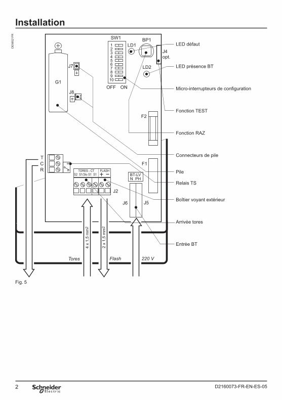
LED défaut
LED présence BT
Micro-interrupteurs de configuration
Fonction TEST
Fonction RAZ
Connecteurs de pile
Pile
Relais TS
Boîtier voyant extérieur
Arrivée tores
Entrée BT
4 x
1,5
mm
2
2 x
1,5
mm
2
Fig. 5
3D2160073-FR-EN-ES-05
Installation
Fran
çais
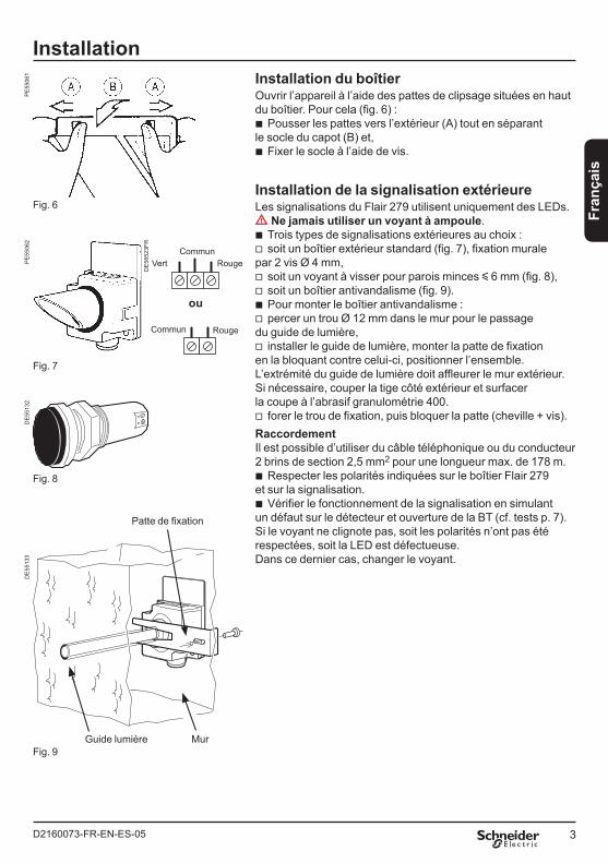
Installation du boîtierOuvrir l’appareil à l’aide des pattes de clipsage situées en hautdu boîtier. Pour cela (fig. 6) :
Pousser les pattes vers l’extérieur (A) tout en séparantle socle du capot (B) et,
Fixer le socle à l’aide de vis.
Installation de la signalisation extérieureLes signalisations du Flair 279 utilisent uniquement des LEDs.dd Ne jamais utiliser un voyant à ampoule.
Trois types de signalisations extérieures au choix :soit un boîtier extérieur standard (fig. 7), fixation murale
par 2 vis Ø 4 mm,soit un voyant à visser pour parois minces y 6 mm (fig. 8),soit un boîtier antivandalisme (fig. 9).Pour monter le boîtier antivandalisme :percer un trou Ø 12 mm dans le mur pour le passage
du guide de lumière,installer le guide de lumière, monter la patte de fixation
en la bloquant contre celui-ci, positionner l’ensemble.L’extrémité du guide de lumière doit affleurer le mur extérieur.Si nécessaire, couper la tige côté extérieur et surfacerla coupe à l’abrasif granulométrie 400.
forer le trou de fixation, puis bloquer la patte (cheville + vis).RaccordementIl est possible d’utiliser du câble téléphonique ou du conducteur2 brins de section 2,5 mm2 pour une longueur max. de 178 m.
Respecter les polarités indiquées sur le boîtier Flair 279 et sur la signalisation.
Vérifier le fonctionnement de la signalisation en simulantun défaut sur le détecteur et ouverture de la BT (cf. tests p. 7).Si le voyant ne clignote pas, soit les polarités n’ont pas étérespectées, soit la LED est défectueuse.Dans ce dernier cas, changer le voyant.
b
b
bv
vvbv
v
v
b
b
Commun
ou
CommunVert Rouge
Rouge
Fig. 6
Fig. 7
Fig. 8
Fig. 9
Patte de fixation
MurGuide lumière
PE
5506
1P
E55
062
DE
5513
2
DE
5852
3FR
DE
5513
3
4 D2160073-FR-EN-ES-05
Installation
A B C
AS2
S2 S1 S1 S1
S1 S1
T1S1S2
Fig. 10
Fig. 11
Fig. 12
4 x 1,5 mm2
S1/3Io
J1
B C
A B C
aefcd
ae
ae
cd
S2
S2 S1 S1 S1
S1 S1
4 x 1,5 mm2
S1/3Io
J1
S2 S1 S1
2 x 1,5 mm2
S1/3Io
J1
T1
T2
T2
S1S2
S1S2
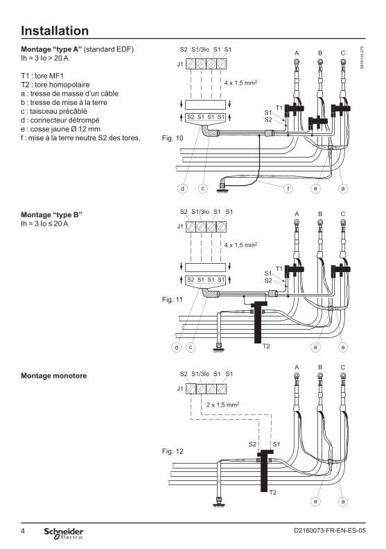
Montage “type A” (standard EDF)Ih = 3 Io > 20 A
T1 : tore MF1 T2 : tore homopolaire a : tresse de masse d’un câbleb : tresse de mise à la terre c : taisceau précâblé d : connecteur détrompé e : cosse jaune Ø 12 mm f : mise à la terre neutre S2 des tores.
Montage “type B”Ih = 3 Io ≤ 20 A
Montage monotore
DE
5513
4-27
9
5D2160073-FR-EN-ES-05
Fran
çais
InstallationInstallation des toresMettre en place le ou les tores sur les câbles MT selon le type de montage choisi (cf. schémas page 6).b Montages tritores
Montage “type A” (standard EDF) 3 tores MF1 + faisceau de raccordement pour courant de défaut phase-terre Ih u 20 A.
Montage “type B” 2 tores MF1 + 1 tore homopolaire + faisceau de raccordement pour courant de défaut phase-terre Ih y 20 A.dd Important Monter les 3 tores dans le même sens. Passer la tresse de masse d’un câble à l’intérieur du tore.b Montage monotore1 tore homopolaire.
dd Important La tresse de mise à la terre doit passer à l’intérieur du tore. Toutes les tresses doivent être isolées.
Sortie contact sec TSConnecter s’il y a lieu la sortie J3
au câble correspondant.Rappel : Travail V point 1 Commun V point 2 Repos V point 3Son pouvoir de coupure est de :
5 A/250 V alternatif,5 A/ 30 V et 0,5 A/100 V continu.
Mise à la terreLe circuit imprimé du détecteur Flair 279 ne nécessite pas de mise à la terre.Il satisfait en effet sans mise à la terre aux essais de CEM (Compatibilité ElectroMagnétique).
v
v
b
vv
Alimentation220/240 V - 50/60 HzNota : le câblage de la basse tension sera effectué conformément aux normes de sécurité locales (NFC 15-100 en France).
Passer le câble 230 V dans le passe-câble situé en face du coupe-circuit J5/J6.
Relier le fil de phase à la borne “PH”.Relier le fil neutre à la borne “N”.
L’alimentation 230 V doit être issue de l’aval d’un coupe-circuit HPC (haut pouvoir de coupure) pour les montages EDF.Lorsque la BT est connectée, la LED témoin de présence BT doit être allumée. Dans le cas contraire, vérifier le coupe-circuit de la carte.
Connecter la pile. Avant toute utilisation du Flair 279, attendre 15 s après une connexion ou reconnexion de la pile.En absence de BT, une autonomie de 400 h est assurée par la pile.Remarque : lors d’un long stockage, le pack de piles peut être passivé, et de ce fait ne pas pouvoir fournir le courant nécessaire au fonctionnement du Flair.Pour le dépassiver :
court-circuiter ses bornes par une résistance 47 ohms - 3 W,
attendre, 10 à 30 s suivant l’état des piles, une élévation décelable de la température de résistance.
b
bb
b
v
v
6 D2160073-FR-EN-ES-05
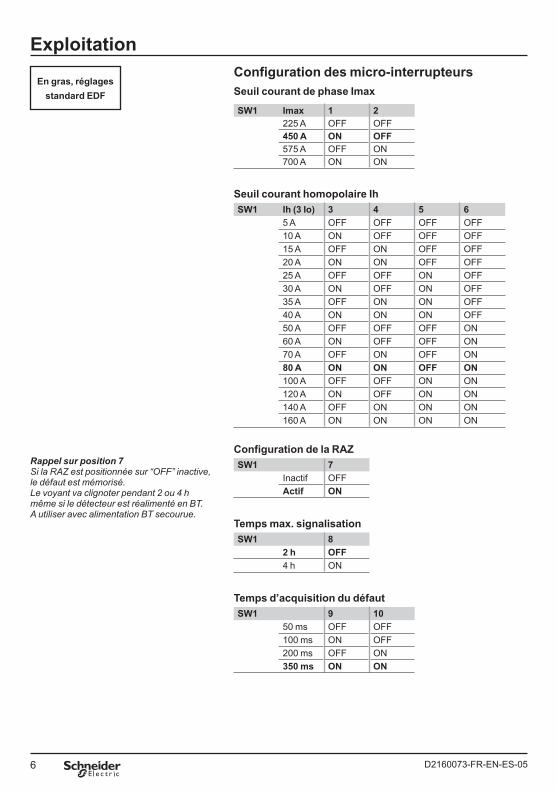
ExploitationConfiguration des micro-interrupteursSeuil courant de phase Imax
SW1 Imax 1 2225 A OFF OFF450 A ON OFF575 A OFF ON700 A ON ON
Seuil courant homopolaire IhSW1 Ih (3 Io) 3 4 5 6
5 A OFF OFF OFF OFF10 A ON OFF OFF OFF15 A OFF ON OFF OFF20 A ON ON OFF OFF25 A OFF OFF ON OFF30 A ON OFF ON OFF35 A OFF ON ON OFF40 A ON ON ON OFF50 A OFF OFF OFF ON60 A ON OFF OFF ON70 A OFF ON OFF ON80 A ON ON OFF ON100 A OFF OFF ON ON120 A ON OFF ON ON140 A OFF ON ON ON160 A ON ON ON ON
Configuration de la RAZSW1 7
Inactif OFFActif ON
Temps max. signalisationSW1 8
2 h OFF4 h ON
Temps d’acquisition du défautSW1 9 10
50 ms OFF OFF100 ms ON OFF200 ms OFF ON350 ms ON ON
En gras, réglagesstandard EDF
Rappel sur position 7Si la RAZ est positionnée sur “OFF” inactive, le défaut est mémorisé.Le voyant va clignoter pendant 2 ou 4 h même si le détecteur est réalimenté en BT. A utiliser avec alimentation BT secourue.
7D2160073-FR-EN-ES-05
Fran
çais
ExploitationGénéralitésLe Flair 279 doit détecter le défaut avant que la protection du départ MT concerné ne déclenche. Pour cela :
Les seuils Ih (courant homopolaire = 3 Io) et Imax (courant entre phases) seront choisis immédiatement inférieurs à ceux de la protection du départ.
Le temps de prise en compte du défaut devra être inférieur au temps total d’ouverture de la protection (relais + disjoncteur).
dd Si ce temps est trop court, le Flair va signaler tous les défauts, y compris les fugitifs. Si ce temps est trop long, le disjoncteur du départ HTA risque de déclencher avant le signalement du défaut.
RéglagesCapot ouvert, positionner les micro-interrupteurs de configuration SW1 selon les tableaux de la page 6.
Test de fonctionnementAprès configuration, procéder à un test de fonctionnement sur les 2 possibilités de RAZ.Position “ON” RAZ par retour BT activée (micro-interrupteur 7 de SW1 sur ON)
Ouvrir l’arrivée BT par J5/J6 ou par le coupe-circuit F1.
Effectuer TEST/RAZ (bouton-poussoir).La signalisation externe et la LED1
(défaut) clignotent, la sortie relais J3 passe en position “travail”.dd Si pendant les 3 premières secondes le clignotement de la LED est rapide, la chaîne de détection est défectueuse.
Attendre 10 s, puis refermer l’arrivée BT.La signalisation s’arrête, J3 passe en
position “repos”.Position “OFF”RAZ par retour BT inactivée :
Effectuer TEST/RAZ.La signalisation externe et la LED1
(défaut) clignotent, la sortie relais J3 passe en position “travail”.
Attendre 10 s, puis effectuer TEST/RAZ.
b
b
b
bb
bb
bb
b
La signalisation s’arrête, J3 passe en position “repos”.Refermer le boîtier en engageant d’abord les pattes inférieures du capot dans le socle et rabattre jusqu’au clipsage.
Test fonctionnelCe test comprend les contrôles de Imax, Ih, temps.Vous pouvez le réaliser si vous disposez d’une valise d’essai VALTEST.Reportez-vous à la notice correspondante.
Détection de défautLe courant de défaut est détecté lorsqu’il a dépassé le seuil 3 Io ou Imax pendant une durée u au temps de prise en compte.La signalisation visuelle se déclenche et le contact J3 du relais TS passe en position “travail” pendant 3 s minimum.La période de clignotement évolue en fonction du temps T passé en signalisation :
2 s (T < 2 h)3 s (T < 3 h)4 s (T < 4 h)
Le retour à l’état de veille est fonction de la programmation RAZ et de la présence ou absence de MT.Position “ON”RAZ par retour BT ou courant activée :
Avec MT présente :immédiat après le retour BT.
Avec MT absente :à la fin de la durée programmée,ou par action volontaire sur TEST/RAZ,ou au retour stable de la MT.
Position “OFF”RAZ par retour BT ou courant inactivée :
A la fin de la durée programmée.Ou par action volontaire sur TEST/RAZ.
b
vvv
b
bvvv
bb
Voir tableaux page 6 :
en gras, réglagesstandard EDF
8 D2160073-FR-EN-ES-05
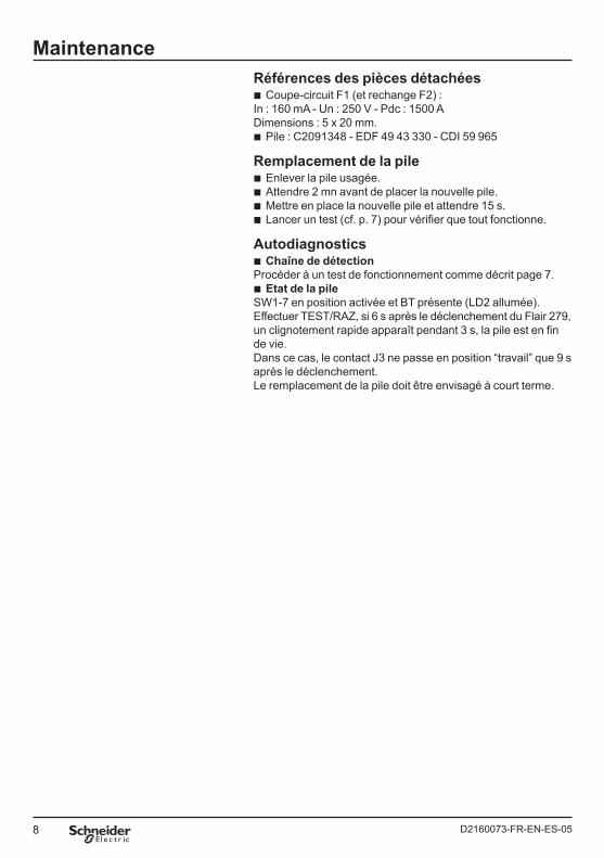
MaintenanceRéférences des pièces détachées
Coupe-circuit F1 (et rechange F2) :In : 160 mA - Un : 250 V - Pdc : 1500 ADimensions : 5 x 20 mm.
Pile : C2091348 - EDF 49 43 330 - CDI 59 965
Remplacement de la pileEnlever la pile usagée.Attendre 2 mn avant de placer la nouvelle pile.Mettre en place la nouvelle pile et attendre 15 s.Lancer un test (cf. p. 7) pour vérifier que tout fonctionne.
AutodiagnosticsChaîne de détection
Procéder à un test de fonctionnement comme décrit page 7.Etat de la pile
SW1-7 en position activée et BT présente (LD2 allumée).Effectuer TEST/RAZ, si 6 s après le déclenchement du Flair 279, un clignotement rapide apparaît pendant 3 s, la pile est en fin de vie.Dans ce cas, le contact J3 ne passe en position “travail” que 9 s après le déclenchement.Le remplacement de la pile doit être envisagé à court terme.
b
b
bbbb
b
b
9D2160073-FR-EN-ES-05
5
1250
202630 M22 x 1
62,5
Dimensions
Fran
çais
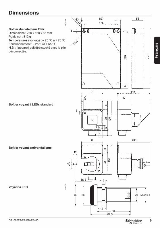
Boîtier du détecteur FlairDimensions : 250 x 160 x 65 mmPoids net : 812 g Températures stockage : – 25 °C à + 70 °CFonctionnement : – 25 °C à + 55 ° CN.B. : l’appareil doit être stocké avec la pile déconnectée.
Boîtier voyant à LEDs standard
Boîtier voyant antivandalisme
Voyant à LED
PE
5506
3D
E55
131

1D2160073-FR-EN-ES-05
Engl
ish
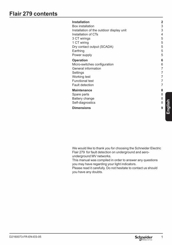
Installation 2Box installation 3Installation of the outdoor display unit 3Installation of CTs 43 CT wirings 51 CT wiring 5Dry contact output (SCADA) 5Earthing 5Power supply 5 Operation 6Micro-switches configuration 6General information 7Settings 7Working test 7Functional test 7Fault detection 7Maintenance 8Spare parts 8Battery change 8Self-diagnostics 8 Dimensions 9
Flair 279 contents
We would like to thank you for choosing the Schneider Electric Flair 279 for fault detection on underground and aero-underground MV networks. This manual was compiled in order to answer any questions you may have regarding your light indicators. Please read it carefully. Do not hesitate to contact us should you have any doubts.
2 D2160073-FR-EN-ES-05
InstallationD
E58
521E
N
OFF
12345678910
SW1
ON
LD1
LD2
G1
TCR
BP1
J4opt.
J7
J8
CT’s
BT-LVN PH
Flash 220 V
J6 J5
J2
S2 S1/3Io S1 S1TORES - CT FLASH
F2
F1
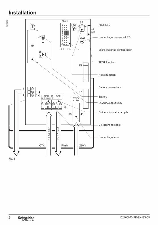
Fault LED
Low voltage presence LED
Micro-switches configuration
TEST function
Reset function
Battery connectors
Battery
SCADA output relay
Outdoor indicator lamp box
CT incoming cable
Low voltage input
4 x
1,5
mm
2
2 x
1,5
mm
2
Fig. 5
3D2160073-FR-EN-ES-05
Engl
ish
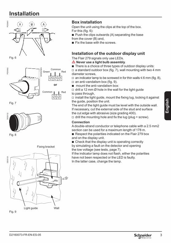
InstallationBox installationOpen the unit using the clips at the top of the box.For this (fig. 6):
Push the clips outwards (A) separating the base from the cover (B) and,
Fix the base with the screws.
Installation of the outdoor display unitThe Flair 279 signals only use LEDs.dd Never use a light bulb assembly.
There is a choice of three types of outdoor display units:a standard outdoor box (fig. 7), wall mounting with two 4 mm
diameter screws,an indicator lamp to be screwed in for thin walls y 6 mm (fig. 8),an anti-vandalism box (fig. 9). mount the anti-vandalism box:drill a 12 mm Ø hole in the wall for the light guide
to pass through,install the light guide, mount the fixing lug, locking it against
the guide, position the unit.The end of the light guide must be level with the outside wall. If necessary, cut the external side of the stud and surface the cut edge with abrasive (size grading 400).
drill the mounting hole and fix the lug (plug + screw).ConnectionA double-strand conductor or telephone cable with a 2.5 mm2 section can be used for a maximum length of 178 m.
Respect the polarities indicated on the Flair 279 box and on the display unit.
Check that the display unit is operating correctly by simulating a fault on the detector and opening the low voltage (see tests, page 7).If the indicator lamp does not flash, either the polarities have not been respected or the LED is faulty. In the latter case, change the lamp.
b
b
bv
vvbv
v
v
b
b
Common
Common
or
Green Red
Red
Fig. 6
Fig. 7
Fig. 8
Fig. 9
Fixing bracket
WallLight guide
PE
5506
1P
E55
062
DE
5513
2
DE
5852
3EN
DE
5513
3
4 D2160073-FR-EN-ES-05
Installation
A B C
AS2
S2 S1 S1 S1
S1 S1
T1S1S2
Fig. 10
Fig. 11
Fig. 12
4 x 1,5 mm2
S1/3Io
J1
B C
A B C
aefcd
ae
ae
cd
S2
S2 S1 S1 S1
S1 S1
4 x 1,5 mm2
S1/3Io
J1
S2 S1 S1
2 x 1,5 mm2
S1/3Io
J1
T1
T2
T2
S1S2
S1S2
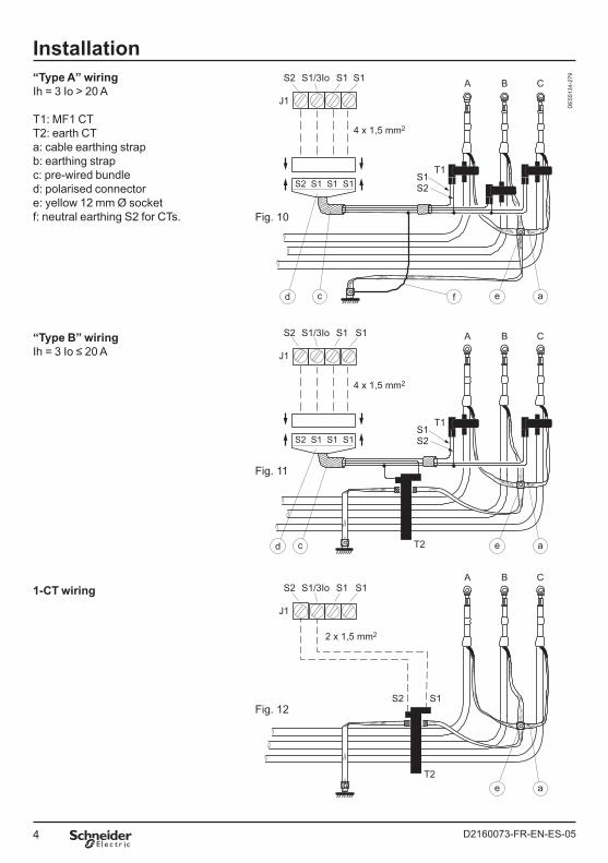
“Type A” wiringIh = 3 Io > 20 A
T1: MF1 CT T2: earth CT a: cable earthing strapb: earthing strap c: pre-wired bundle d: polarised connector e: yellow 12 mm Ø socket f: neutral earthing S2 for CTs.
“Type B” wiringIh = 3 Io ≤ 20 A
1-CT wiring
DE
5513
4-27
9
5D2160073-FR-EN-ES-05
Engl
ish
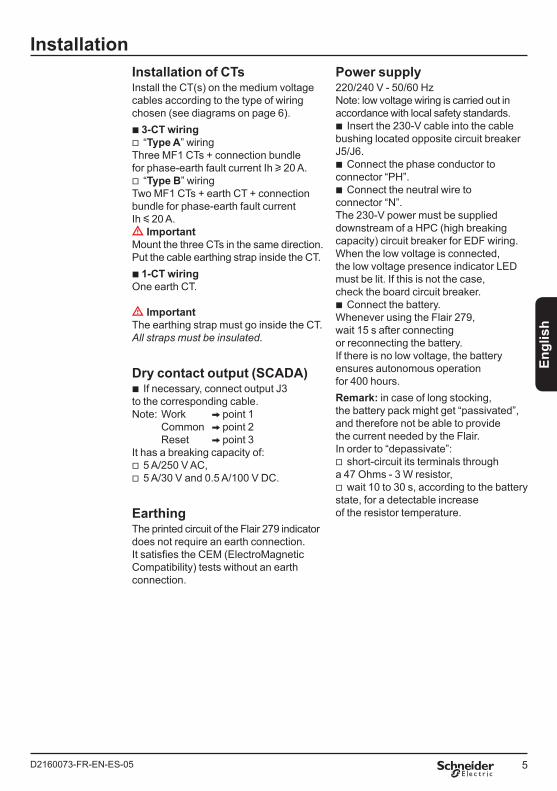
InstallationInstallation of CTsInstall the CT(s) on the medium voltage cables according to the type of wiring chosen (see diagrams on page 6).b 3-CT wiring
“Type A” wiring Three MF1 CTs + connection bundle for phase-earth fault current Ih u 20 A.
“Type B” wiring Two MF1 CTs + earth CT + connection bundle for phase-earth fault currentIh y 20 A.dd Important Mount the three CTs in the same direction.Put the cable earthing strap inside the CT.b 1-CT wiringOne earth CT.
dd Important The earthing strap must go inside the CT. All straps must be insulated.
Dry contact output (SCADA)If necessary, connect output J3
to the corresponding cable.Note: Work V point 1 Common V point 2 Reset V point 3It has a breaking capacity of:
5 A/250 V AC,5 A/30 V and 0.5 A/100 V DC.
EarthingThe printed circuit of the Flair 279 indicator does not require an earth connection. It satisfies the CEM (ElectroMagnetic Compatibility) tests without an earth connection.
v
v
b
vv
Power supply220/240 V - 50/60 HzNote: low voltage wiring is carried out in accordance with local safety standards.
Insert the 230-V cable into the cable bushing located opposite circuit breaker J5/J6.
Connect the phase conductor to connector “PH”.
Connect the neutral wire to connector “N”.The 230-V power must be supplied downstream of a HPC (high breaking capacity) circuit breaker for EDF wiring. When the low voltage is connected, the low voltage presence indicator LED must be lit. If this is not the case, check the board circuit breaker.
Connect the battery. Whenever using the Flair 279, wait 15 s after connecting or reconnecting the battery.If there is no low voltage, the battery ensures autonomous operation for 400 hours.Remark: in case of long stocking, the battery pack might get “passivated”, and therefore not be able to provide the current needed by the Flair. In order to “depassivate”:
short-circuit its terminals through a 47 Ohms - 3 W resistor,
wait 10 to 30 s, according to the battery state, for a detectable increase of the resistor temperature.
b
b
b
b
v
v
6 D2160073-FR-EN-ES-05
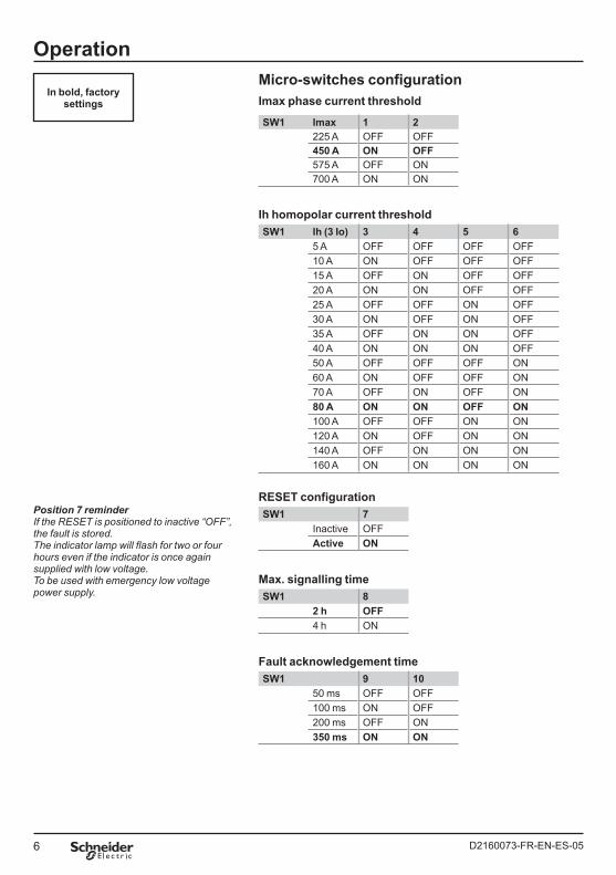
OperationMicro-switches configurationImax phase current threshold
SW1 Imax 1 2225 A OFF OFF450 A ON OFF575 A OFF ON700 A ON ON
Ih homopolar current thresholdSW1 Ih (3 Io) 3 4 5 6
5 A OFF OFF OFF OFF10 A ON OFF OFF OFF15 A OFF ON OFF OFF20 A ON ON OFF OFF25 A OFF OFF ON OFF30 A ON OFF ON OFF35 A OFF ON ON OFF40 A ON ON ON OFF50 A OFF OFF OFF ON60 A ON OFF OFF ON70 A OFF ON OFF ON80 A ON ON OFF ON100 A OFF OFF ON ON120 A ON OFF ON ON140 A OFF ON ON ON160 A ON ON ON ON
RESET configurationSW1 7
Inactive OFFActive ON
Max. signalling timeSW1 8
2 h OFF4 h ON
Fault acknowledgement timeSW1 9 10
50 ms OFF OFF100 ms ON OFF200 ms OFF ON350 ms ON ON
Position 7 reminderIf the RESET is positioned to inactive “OFF”, the fault is stored. The indicator lamp will flash for two or four hours even if the indicator is once again supplied with low voltage. To be used with emergency low voltage power supply.
In bold, factory settings
7D2160073-FR-EN-ES-05
Engl
ish
OperationGeneral informationThe Flair 279 must detect the fault before the relevant medium voltage output protection can be triggered. For this:
The Ih (homopolar current = 3 lo) and Imax (current between phases) thresholds are chosen to be immediately below the output protection thresholds.
The fault processing time should be shorter than the total on-period of the protection (relay + circuit breaker).
dd If the set time is too short, the Flair will trigger for all faults, including transient faults. If the set time is too long, the Flair will not signal the fault.
SettingsWith the cover open, position the SW1 configuration micro-switches according to the tables on page 6.
Working testAfter configuration, perform an operational test on the two possibilities of RESET.“ON” position RESET by activated low voltage return:
Open the low voltage incoming cable with J5/J6 or the F1 circuit breaker.
Perform TEST/RESET.The outdoor display unit and LED1
(fault) flash, relay output J3 moves into “work” position. dd If the LED flashes quickly for the first three seconds, the detection chain is faulty.
Wait 10 seconds, then close the low voltage incoming cable.
The signalling stops, J3 moves into “rest” position.“OFF” positionRESET by inactivated low voltage return:
Perform TEST/RESET.The outside display unit and LED1
(fault) flash, relay output J3 moves into “work” position.
Wait 10 s, then perform TEST/RESET.The signalling stops, J3 moves into
“rest” position.Shut the box by latching the lower lugs
b
b
b
bb
b
b
bb
bb
of the cover onto the base and pushing it down until it snaps on.
Functional testThis test includes Imax, Ih and time checks. This test can be performed with a VALTEST portable testing unit.Please refer to the relevant manual.
Fault detectionThe fault current is detected when it exceeds the 3 Io or Imax threshold for a duration u the processing time.The visual signal is triggered and contact J3 of SCADA output moves into “work” position for 3 s minimum.The flashing period changes according to the signalling time T:
2 s (T < 2 h)3 s (T < 3 h)4 s (T < 4 h)
The return to standby state depends on the RESET programming and on the presence or absence of MV.“ON” positionRESET by activated LV or current return:
With MV:immediately after the LV return.
Without MV:at the end of the duration programmed,by activating TEST/RESET voluntarily,or at the stable return of the MV.
“OFF” positionRESET by inactivated LV or current return:
At the end of the duration programmed.Or by activating TEST/RESET
voluntarily.
vvv
b
bvvv
bb
8 D2160073-FR-EN-ES-05
MaintenanceSpare part references
Fuse F1 (and replacement F2):In: 160 mA - Un: 250 V - Pdc: 1500 ADimensions: 5 x 20 mm.
Battery: C2091348 - EDF 49 43 330 - CDI 59 965
Battery replacementRemove the used battery.Wait two minutes before inserting the new battery.Insert the new battery and wait 15 s.Start the test (see p. 7) to check that it is operating correctly.
Self-diagnosticsDetection chain
Perform an operational test as described on page 7 according.Battery status
SW1-7 in activated position and low voltage present (LD2 lit).Perform TEST/RESET, if six seconds after the Flair 279 is triggered, there is rapid flashing for three seconds, the battery is at the end of its life. In this case, contact J3 only moves into “work” position nine seconds after the triggering. Battery replacement must be planned in the short term.
b
b
bbbb
b
b
9D2160073-FR-EN-ES-05
Engl
ish
5
1250
202630 M22 x 1
62,5
Dimensions
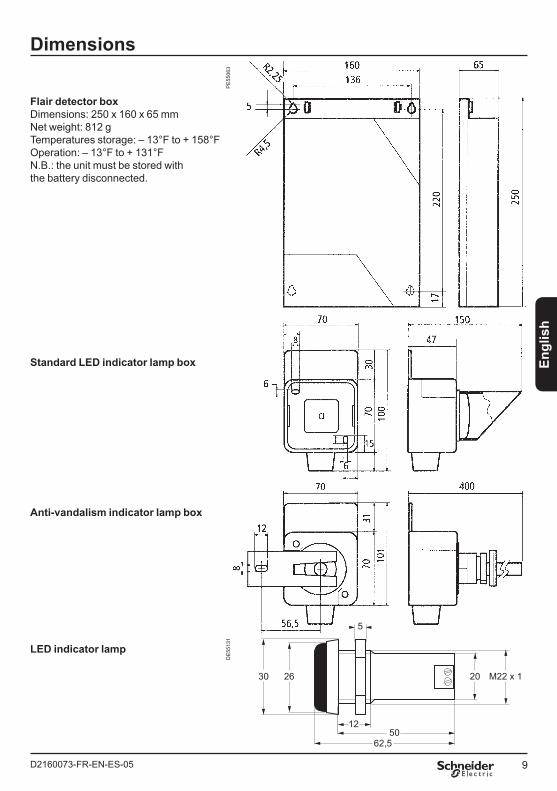
Flair detector boxDimensions: 250 x 160 x 65 mmNet weight: 812 g Temperatures storage: – 13°F to + 158°FOperation: – 13°F to + 131°FN.B.: the unit must be stored with the battery disconnected.
Standard LED indicator lamp box
Anti-vandalism indicator lamp box
LED indicator lamp
PE
5506
3D
E55
131

1D2160073-FR-EN-ES-05
Espa
ñol
Instalación 2Instalación de la caja 3Instalación de la caja externa de señalización 3Instalación de los sensores 4Montajes con 3 sensores 5Montaje con 1 sensor 5Salida contacto seco TS 5Conexión a tierra 5Alimentación 5 Explotación 6Micro-interruptores de configuración 6Generalidades 7Ajustes 7Test de funcionamiento 7Test funcional 7Detección de fallas 7Mantenimiento 8Piezas de recambio 8Sustitución de la pila 8Auto-diagnósticos 8 Dimensiones 9
Tabla Flair 279
Le agradecemos que haya elegido Flair 279 de Schneider Electric para la detección de defectos en redes de media tensión subterráneas o aéro-subterráneas. Este manual se ha elaborado con objeto de contestar a todas las preguntas que pueda plantearse sobre sus indicadores luminosos. Léalo atentamente. No dude en ponerse en contacto con nosotros en caso de dudas.
2 D2160073-FR-EN-ES-05
InstalaciónD
E58
521E
S
OFF
12345678910
SW1
ON
LD1
LD2
G1
TCR
BP1
J4opt.
J7
J8
Toroides
BT-LVN PH
Flash 220 V
J6 J5
J2
S2 S1/3Io S1 S1TORES - CT FLASH
F2
F1
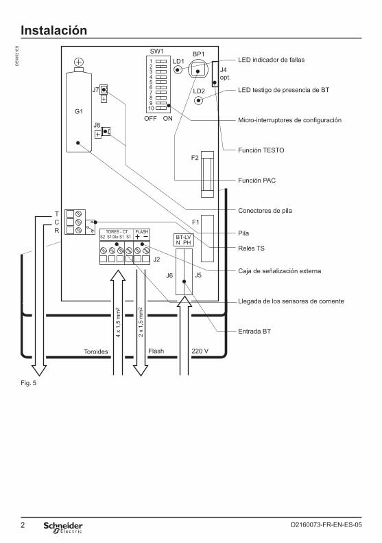
LED indicador de fallas
LED testigo de presencia de BT
Micro-interruptores de configuración
Función TESTO
Función PAC
Conectores de pila
Pila
Relés TS
Caja de señalización externa
Llegada de los sensores de corriente
Entrada BT
4 x
1,5
mm
2
2 x
1,5
mm
2
Fig. 5
3D2160073-FR-EN-ES-05
Espa
ñol
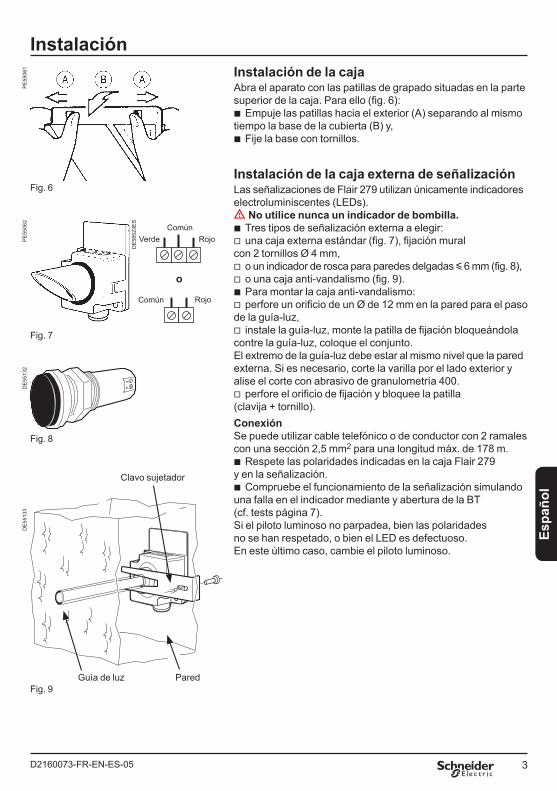
InstalaciónInstalación de la cajaAbra el aparato con las patillas de grapado situadas en la parte superior de la caja. Para ello (fig. 6):
Empuje las patillas hacia el exterior (A) separando al mismo tiempo la base de la cubierta (B) y,
Fije la base con tornillos.
Instalación de la caja externa de señalizaciónLas señalizaciones de Flair 279 utilizan únicamente indicadores electroluminiscentes (LEDs).dd No utilice nunca un indicador de bombilla.
Tres tipos de señalización externa a elegir:una caja externa estándar (fig. 7), fijación mural
con 2 tornillos Ø 4 mm,o un indicador de rosca para paredes delgadas y 6 mm (fig. 8),o una caja anti-vandalismo (fig. 9).Para montar la caja anti-vandalismo:perfore un orificio de un Ø de 12 mm en la pared para el paso
de la guía-luz,instale la guía-luz, monte la patilla de fijación bloqueándola
contre la guía-luz, coloque el conjunto. El extremo de la guía-luz debe estar al mismo nivel que la pared externa. Si es necesario, corte la varilla por el lado exterior y alise el corte con abrasivo de granulometría 400.
perfore el orificio de fijación y bloquee la patilla (clavija + tornillo).ConexiónSe puede utilizar cable telefónico o de conductor con 2 ramales con una sección 2,5 mm2 para una longitud máx. de 178 m.
Respete las polaridades indicadas en la caja Flair 279 y en la señalización.
Compruebe el funcionamiento de la señalización simulando una falla en el indicador mediante y abertura de la BT(cf. tests página 7).Si el piloto luminoso no parpadea, bien las polaridades no se han respetado, o bien el LED es defectuoso. En este último caso, cambie el piloto luminoso.
b
b
bv
vvbv
v
v
b
b
Común
Común
o
Verde Rojo
Rojo
Fig. 6
Fig. 7
Fig. 8
Fig. 9
Clavo sujetador
ParedGuía de luz
PE
5506
1P
E55
062
DE
5513
2
DE
5852
3ES
DE
5513
3
4 D2160073-FR-EN-ES-05
Instalación
A B C
AS2
S2 S1 S1 S1
S1 S1
T1S1S2
Fig. 10
Fig. 11
Fig. 12
4 x 1,5 mm2
S1/3Io
J1
B C
A B C
aefcd
ae
ae
cd
S2
S2 S1 S1 S1
S1 S1
4 x 1,5 mm2
S1/3Io
J1
S2 S1 S1
2 x 1,5 mm2
S1/3Io
J1
T1
T2
T2
S1S2
S1S2
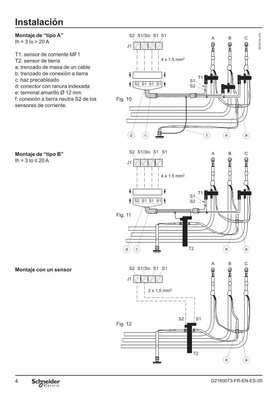
Montaje de “tipo B”Ih = 3 Io ≤ 20 A
Montaje con un sensor
DE
5513
4-27
9Montaje de “tipo A”Ih = 3 Io > 20 A
T1: sensor de corriente MF1 T2: sensor de tierra a: trenzado de masa de un cableb: trenzado de conexión a tierra c: haz precableado d: conector con ranura indexada e: terminal amarillo Ø 12 mm f: conexión a tierra neutra S2 de los sensores de corriente.
5D2160073-FR-EN-ES-05
Espa
ñol
InstalaciónInstalación de los sensoresColoque el o los sensores de corriente en los cables MT según el tipo de montaje escogido (cf. esquemas de las página 6).b Montajes con tres sensores
Montaje de “tipo A” 3 sensores de corriente MF1 + haz de conexión para corriente de defecto fase-tierra Ih u 20 A.
Montaje de “tipo B” 2 sensores de corriente MF1 + 1 sensor de corriente a tierra + haz de conexión para corriente de defecto fase-tierra Ih y 20 A.dd Importante Monte los 3 sensores de corriente en el mismo sentido.Pase el trenzado de masa de un cable por dentro del sensor.b Montaje con un sensor1 sensor de corriente a tierra.
dd Importante El trenzado de conexión a tierra debe pasar por dentro del sensor laminado. Todos los trenzados deben estar aislados.
Salida contacto seco TSConecte, si es necesario, la salida J3
al cable correspondiente.Nota: Trabajo V punto 1 Común V punto 2 Reposo V punto 3Su poder de corte es de:
5 A/250 V alterna,5 A/ 30 V y 0,5 A/100 V continua.
Conexión a tierraEl circuito impreso del indicador Flair 279 no requiere conexión a tierra. Supera, sin conexión a tierra, las pruebas de CEM (Compatibilidad ElectroMagnética).
v
v
b
vv
Alimentación220/240 V - 50/60 HzNota: el cableado de baja tensión se efectuará de acuerdo con las normas de seguridad locales.
Pase el cable 230 V por el pasacables situado enfrente del cortacircuito J5/J6.
Conecte el hilo de fase al borne “PH”.Conecte el hilo neutro al borne “N”.
La alimentación 230 V debe estar situada después de un fusible HPC (alta potencia de corte) para los montajes EDF.Cuando la BT está conectada, el LED testigo de presencia de BT debe estar encendido. Si no es así, compruebe el fusible de la tarjeta.
Conecte la pila.Cada vez que utilice Flair 279, espere 15 s tras una conexióno reconexión de la pila.Cuando no hay BT, la pila garantiza una autonomía de 400 h.Nota: después de quedar sin funcionar la batería puede ser “pasivada”, en este caso no dara el corriente suficiente para el funcionamiento del Flair. Para poner in orden de marcha la batería:
hacer un corte-circuito entra sus bornes con una resistencia de 47 Ohms - 3 W,
esperar 10 o 30 s según el estado de la batería una elevación sensible de la temperatura de la resistencia.
b
bb
b
v
v
6 D2160073-FR-EN-ES-05
Explotación
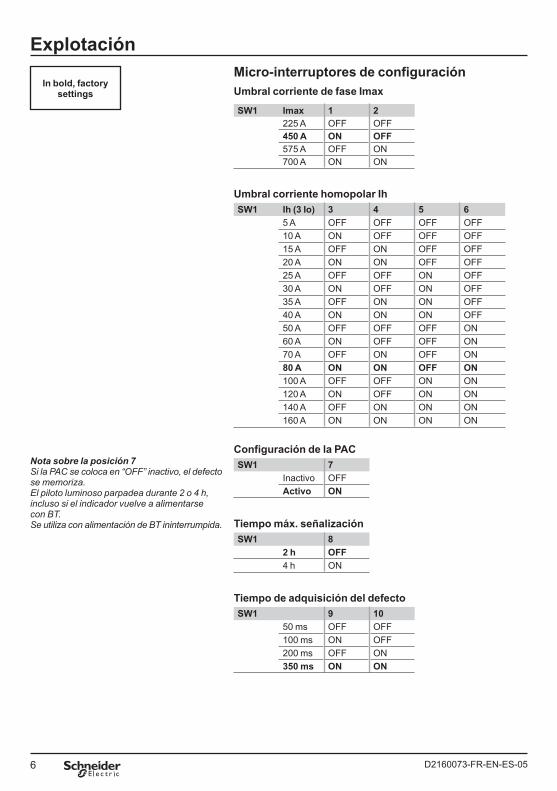
Nota sobre la posición 7Si la PAC se coloca en “OFF” inactivo, el defecto se memoriza. El piloto luminoso parpadea durante 2 o 4 h, incluso si el indicador vuelve a alimentarse con BT. Se utiliza con alimentación de BT ininterrumpida.
Micro-interruptores de configuraciónUmbral corriente de fase Imax
SW1 Imax 1 2225 A OFF OFF450 A ON OFF575 A OFF ON700 A ON ON
Umbral corriente homopolar IhSW1 Ih (3 Io) 3 4 5 6
5 A OFF OFF OFF OFF10 A ON OFF OFF OFF15 A OFF ON OFF OFF20 A ON ON OFF OFF25 A OFF OFF ON OFF30 A ON OFF ON OFF35 A OFF ON ON OFF40 A ON ON ON OFF50 A OFF OFF OFF ON60 A ON OFF OFF ON70 A OFF ON OFF ON80 A ON ON OFF ON100 A OFF OFF ON ON120 A ON OFF ON ON140 A OFF ON ON ON160 A ON ON ON ON
Configuración de la PACSW1 7
Inactivo OFFActivo ON
Tiempo máx. señalizaciónSW1 8
2 h OFF4 h ON
Tiempo de adquisición del defectoSW1 9 10
50 ms OFF OFF100 ms ON OFF200 ms OFF ON350 ms ON ON
In bold, factory settings
7D2160073-FR-EN-ES-05
Espa
ñol
ExplotaciónGeneralidadesFlair 279 debe detectar el defecto antes de que la protección inicial MT correspondiente se active. Para ello:
Se seleccionarán los umbrales Ih (corriente homopolar = 3 Io) y Imax (corriente entre fases) inmediatamente inferiores a los de la protección inicial.
El tiempo de integración del defecto debe ser inferior al tiempo total de apertura de la protección (relé + disyuntor).
dd Si el tiempo es muy bajo, el Flair va a detectar todos los defectos, incluyendo los defectos transitorios. Si el tiempo es muy largo, el Flair no va a parpadear.
AjustesCon la cubierta abierta, coloque los micro-interruptores de configuración SW1 de acuerdo con los cuadros de la página 6.
Test de funcionamientoTras la configuración, realice una prueba de funcionamiento en las 2 posibilidades de la PAC.Posición “ON” PAC mediante retorno de BT activada:
Abra la llegada BT por J5/J6 o mediante el fusible F1.
Efectúe TEST/PAC.La señalización externa y el LED1
(falla) parpadean, la salida relé J3 vuelve a la posición “trabajo”.dd Si durante los 3 primeros segundos el parpadeo del LED es rápido, la cadena de detección está averiada.
Espere 10 s y cierre la llegada de BT.La señalización se para, J3 vuelve
a la posición “reposo”.Posición “OFF”PAC mediante vuelta BT desactivada:
Efectúe TEST/PAC.La señalización externa y el LED1
(falla) parpadean, la salida relé J3 vuelve a la posición “trabajo”.
Espere 10 s y cierre la llegada de BT.La señalización se para, J3 vuelve
a la posición “reposo”.
b
b
b
bb
bb
bb
bb
Cierre la caja acoplando primero las patillas inferiores de la cubierta en la base y repliegue hasta que se grape.
Test funcionalEste test incluye los controles de Imax, Ih y tiempo.Puede realizarlo si dispone de una maleta de prueba VALTEST. Remítase al manual correspondiente.
Detección de fallasLa corriente de defecto se detecta cuando supera el umbral 3 Io o Imax durante un periodo de tiempo u al tiempo de integración.La señalización visual se activa y el contacto J3 del relé TS pasa a la posición “trabajo” durante 3 s como mínimo.El periodo de parpadeo varia en función del tiempo T pasado en señalización:
2 s (T < 2 h)3 s (T < 3 h)4 s (T < 4 h)
La vuelta al estado de espera depende de la programación PAC y de la presencia o ausencia de MT.Posición “ON”PAC mediante retorno de BT o del corriente activada:
Con MT presente:inmediato tras la vuelta BT.
Con MT ausente:al final del periodo de tiempo
programado,o mediante acción voluntaria
en TEST/PAC,o a la vuelta estable de la MT.
Posición “OFF”PAC mediante vuelta BT o del corriente desactivada:
Al final del periodo de tiempo programado.
O mediante acción voluntaria en TEST/PAC.
vvv
b
bv
v
v
b
b
8 D2160073-FR-EN-ES-05
MantenimientoReferencias de las piezas de recambio
Fusible F1 (y recambio F2):In: 160 mA - Un: 250 V - Pdc: 1500 ADimensiones: 5 x 20 mm.
Pila: C2091348 - EDF 49 43 330 - CDI 59 965
Sustitución de la pilaRetire la pila gastada.Espere 2 min antes de colocar la pila nueva.Coloque la pila nueva y espere 15 s.Inicie un test (cf. página 7) para comprobar que todo
funciona bien.
Auto-diagnósticosCadena de detección
Realice una prueba de funcionamiento como se describe en la página 7.
Estado de la pilaSW1-7 en posición activada y BT presente (LD2 encendido).Efectúe TEST/PAC, si 6 s después de la activación de Flair 279 aparece un parpadeo rápido durante 3 s, la pila está gastada.En este caso, el contacto J3 sólo se coloca en posición “trabajo” 9 s después de la activación.La pila debe sustituirse a corto plazo.
b
b
bbbb
b
b
9D2160073-FR-EN-ES-05
Espa
ñol
5
1250
202630 M22 x 1
62,5
Dimensiones
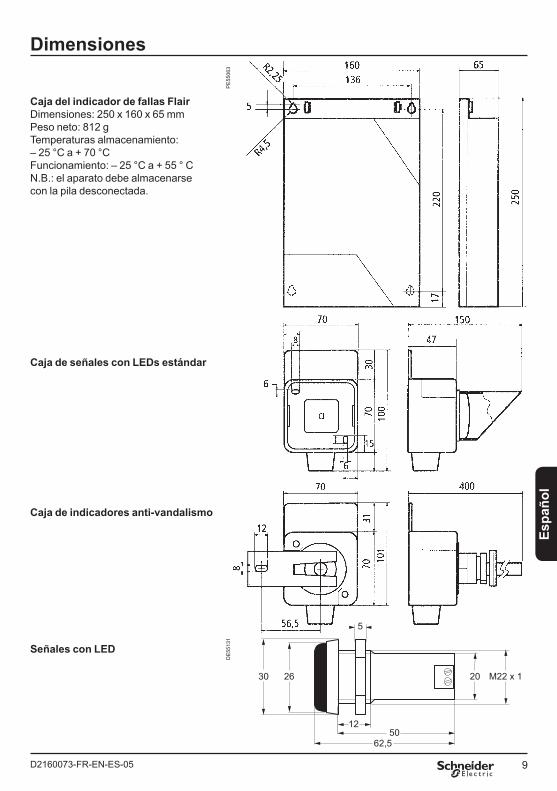
Caja del indicador de fallas FlairDimensiones: 250 x 160 x 65 mmPeso neto: 812 g Temperaturas almacenamiento: – 25 °C a + 70 °CFuncionamiento: – 25 °C a + 55 ° CN.B.: el aparato debe almacenarse con la pila desconectada.
Caja de señales con LEDs estándar
Caja de indicadores anti-vandalismo
Señales con LED
PE
5506
3D
E55
131

D2160073-FR-EN-ES-05 07-2008
En raison de l’évolution des normes et du matériel, les caractéristiques indiquées par les textes et les images de ce document ne nous engagent qu’après confirmation par nos services.As standards, specifications and designs change from time to time, please ask for confirmation of the information given in this publication.Debido a la evolución de las normas y del material, las características y dimensiones indicadasen el texto y las imágenes nos comprometen solamente previa confirmación de nuestros servicios.
Publication: Schneider Electric TelecontrolProduction: GraphèmePrinting: Schneider Electric Telecontrol - Made in France
This document has been printed on ecological paper
Schneider Electric Telecontrol 839 Chemin des BattersesZ.I. Ouest 01700 St Maurice de BeynostTel.: +33 (0)4 78 55 13 13Fax: +33 (0)4 78 55 50 00
http://www.schneider-electric.comE-mail: [email protected]
Schneider Electric Industries SAS


![:.0 ~W ~4*;;]4 - csb.gov.lb · 1- Exprimer la composante homopolaire des courants en regime triphase desequilibre et en deduire Ie role d'un relais homopolaire . II ... Comment obtient-on](https://img.pdfslide.fr/doc/110x75/5b9d9b9909d3f253158c7ed7/0-w-44-csbgovlb-1-exprimer-la-composante-homopolaire-des-courants.jpg)