Embed Size (px)
Citation preview
8/18/2019 frf.5
http://slidepdf.com/reader/full/frf5 1/19
Frame Relay/ATM PVC Network InterworkingImplementation Agreement
December 20, 1994
Editor: Doug O'Leary, Bell AtlanticTel: 215.466.2386
Fax: 215.564.2540
Internet: [email protected]
Secretariat
Frame Relay Forum
The Frame Relay Forum
Document Number FRF.5
Abstract
This Implementation Agreement provides the functional requirements configurations across
interfaces for network interworking between the Frame Relaying Bearer Service and B-ISDN
Permanent Virtual Connection Services.
8/18/2019 frf.5
http://slidepdf.com/reader/full/frf5 2/19
2
Frame Relay / ATM Network Interworking
Implementation Agreement
1.0 Introduction
1.1 Purpose
This document is an implementation agreement on Permanent Virtual Connection (PVC) network
interworking between Frame Relay and Asynchronous Transfer Mode (ATM) technologies. The
agreements herein were reached jointly by the Frame Relay and the ATM Forums and are based
on the relevant standards referenced in section 2.0. These agreements address the optional parts
of these standards, and document agreements reached among vendors and suppliers of frame relayand ATM products and services.
Except as noted, these agreements will form the basis of conformance test suites produced by the
Frame Relay Forum and the ATM Forum.
This document may be submitted to other bodies involved in ratification of implementation
agreements and conformance testing to facilitate multi-vendor interoperability.
This document does not cover Q.933/Q.2931 protocol mapping.
1.2 Overview
Section 3 provides a description of the various interworking scenarios. Section 4 provides
implementation agreements with respect to the protocol interworking functions needed to support
ITU-T I.555 Interworking Scenarios 1 and 2. The material in sections 3, 4, and 5 was jointly
developed by the ATM Forum and the Frame Relay Forum. This document does not cover
service interworking.
1.3 Definitions
The first two definitions are according to ITU-T I.555:
Protocol encapsulation occurs when the conversions in the network or in the terminals are such
that the protocols used to provide one service make use of the layer service provided by another
protocol. This means that at the interworking point, the two protocols are stacked. When
8/18/2019 frf.5
http://slidepdf.com/reader/full/frf5 3/19
3
encapsulation is performed by the terminal, this scenario is also called interworking by port
access.
Protocol mapping occurs when the network performs conversions in such a way that within a
common layer service, the protocol information of one protocol is extracted and mapped on
protocol information of another protocol. This means that each communication terminal supportsdifferent protocols. The common layer service provided in this interworking scenario is defined
by the functions which are common to the two protocols.
Must, Shall or Mandatory - the item is an absolute requirement of this implementation
agreement.
Should - the item is highly desirable.
May or Optional - the item is not compulsory, and may be followed or ignored according to the
needs of the implementor.
Not Applicable - the item is outside the scope of this implementation agreement.
1.4 Acronyms
AAL ATM Adaptation Layer
ATM Asynchronous Transfer Mode
Bc Committed Burst
Be Excess Burst
BECN Backward Explicit Congestion NotificationB-ICI Broadband Inter Carrier Interface
B-ISDN Broadband Integrated Services Digital Network
B-TE T-ISDN Terminal Equipment
CDV Cell Delay Variance
CI Congestion Indication
CIR Committed Information Rate
CLP Cell Loss Priority
CPE Customer Premises Equipment
CPCS Common Part Convergence Sub-layer
CRC Cyclic Redundancy Check
C/R Command/Response bitCSU Channel Service Unit
DE Discard Eligibility
DLCI Data Link Connection Identifier
DSAP Destination Service Access Point
DSU Data Service Unit
DTE Data Terminal Equipment
DTP Data Transfer Protocol
8/18/2019 frf.5
http://slidepdf.com/reader/full/frf5 4/19
4
DXI Data Exchange Interface
EA Address Extension bit
EFCI Explicit Forward Congestion Indicator
FECN Forward Explicit Congestion Notification
FFS For Further Study
FMBS Frame Mode Bearer ServiceFR Frame Relaying
FRBS Frame Relaying Bearer Service
FR-SSCS Frame Relaying - Service Specific Convergence Sub-layer
FRS Frame Relaying Service
FSBS Frame Switching Bearer Service
GCRA Generic Cell Rate Algorithm
IE Information Element
IETF Internet Engineering Task Force
ILMI Interim Local Management Interface
ITU International Telecommunication Union
ITU-T ITU Telecommunications SectorIWF InterWorking Function
LAN Local Area Network
LAPB Link Access Procedure Balanced
LLC Lower Layer Compatibility (in the case of ISDN) or Logical Link Control (in the
case of LAN)
LP Loss Priority
MAC Media Access Control
MBS Maximum Burst Size
MIB Management Information Base
NLPID Network Layer Protocol Identifier
NNI Network to Network Interface NPC Network Parameter Control
OAM Operation, Administration and Maintenance
PDU Protocol Data Unit
PCI Protocol Control Information
PCR Peak Cell Rate
PLP Packet Level Procedures
PSPDN Packet Switched Public Data Network
PVC Permanent Virtual Connection
QoS Quality of Service
RFC Request for Comments
SAP Service Access Point
SAPI Service Access Point Identifier
SAR Segmentation and Reassembly
SCR Sustainable Cell Rate
SNMP Simple Network Management Protocol
SDU Service Data Unit
SSAP Source Service Access Point
8/18/2019 frf.5
http://slidepdf.com/reader/full/frf5 5/19
5
SSCS Service Specific Convergence Sub-layer
SVC Switched Virtual Connection
TA Terminal Adapter
TE Terminal Equipment
U-Plane User Plane
UNI User to Network InterfaceUPC Usage Parameter Control
VC Virtual Connection
VCC Virtual Channel Connection
VCI Virtual Channel Identifier
VPC Virtual Path Connection
VPI Virtual Path Identifier
WAN Wide Area Network
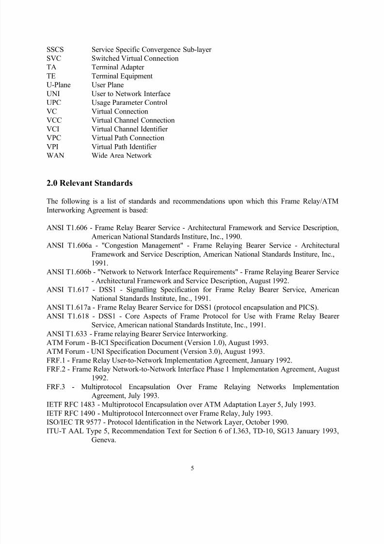
2.0 Relevant Standards
The following is a list of standards and recommendations upon which this Frame Relay/ATM
Interworking Agreement is based:
ANSI T1.606 - Frame Relay Bearer Service - Architectural Framework and Service Description,
American National Standards Institure, Inc., 1990.
ANSI T1.606a - "Congestion Management" - Frame Relaying Bearer Service - Architectural
Framework and Service Description, American National Standards Institure, Inc.,
1991.
ANSI T1.606b - "Network to Network Interface Requirements" - Frame Relaying Bearer Service
- Architectural Framework and Service Description, August 1992.
ANSI T1.617 - DSS1 - Signalling Specification for Frame Relay Bearer Service, American
National Standards Institute, Inc., 1991.
ANSI T1.617a - Frame Relay Bearer Service for DSS1 (protocol encapsulation and PICS).
ANSI T1.618 - DSS1 - Core Aspects of Frame Protocol for Use with Frame Relay Bearer
Service, American national Standards Institute, Inc., 1991.
ANSI T1.633 - Frame relaying Bearer Service Interworking.
ATM Forum - B-ICI Specification Document (Version 1.0), August 1993.
ATM Forum - UNI Specification Document (Version 3.0), August 1993.
FRF.1 - Frame Relay User-to-Network Implementation Agreement, January 1992.
FRF.2 - Frame Relay Network-to-Network Interface Phase 1 Implementation Agreement, August
1992.FRF.3 - Multiprotocol Encapsulation Over Frame Relaying Networks Implementation
Agreement, July 1993.
IETF RFC 1483 - Multiprotocol Encapsulation over ATM Adaptation Layer 5, July 1993.
IETF RFC 1490 - Multiprotocol Interconnect over Frame Relay, July 1993.
ISO/IEC TR 9577 - Protocol Identification in the Network Layer, October 1990.
ITU-T AAL Type 5, Recommendation Text for Section 6 of I.363, TD-10, SG13 January 1993,
Geneva.
8/18/2019 frf.5
http://slidepdf.com/reader/full/frf5 6/19
6
ITU-T I.122 - Framework for Providing Additional Packet Mode Bearer Service, ITU, Geneva,
1988.
ITU-T I.233.1 - Frame Relaying Bearer Services, 1991.
ITU-T I.365.1 - Frame Relaying Service Specific Convergence Sublayer (FR-SSCS), 1993.
ITU-T I.370 - Congestion Management in Frame Relaying Networks, 1991.
ITU-T I.372 - Frame Mode Bearer Service, Network to Network Interface Requirements, 1992.ITU-T I.555 - Frame Relaying Bearer Service Interworking, Com 13 R2-E, July 1994.
ITU-T I.610 - B-ISDN Operations and Maintenance Principles and Maintenance - Proposed Text
on the Loopback Capability, 1993.
ITU-T Q.922 - ISDN Data Link Layer Specifications for Frame Mode Bearer Services, 1992.
ITU-T Q.933 - DSS1 Signalling Specifications for Frame Mode Basic Call Control, ITU,
Geneva, 1992.
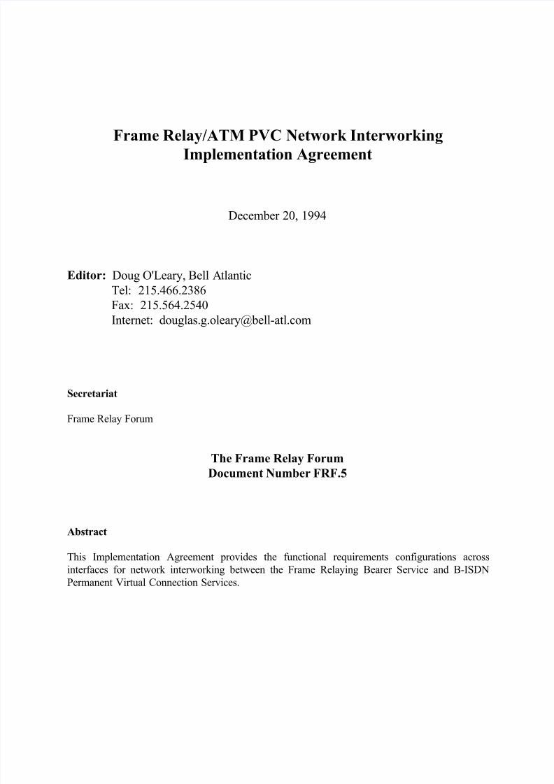
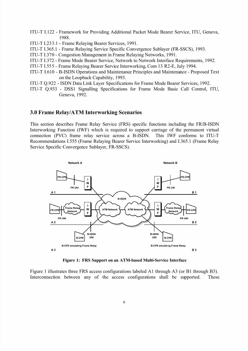
3.0 Frame Relay/ATM Interworking Scenarios
This section describes Frame Relay Service (FRS) specific functions including the FR/B-ISDNInterworking Function (IWF) which is required to support carriage of the permanent virtual
connection (PVC) frame relay service across a B-ISDN. This IWF conforms to ITU-T
Recommendations I.555 (Frame Relaying Bearer Service Interworking) and I.365.1 (Frame Relay
Service Specific Convergence Sublayer, FR-SSCS).
FR UNI
ATM Network ATM Network
I
W
F
I
WF
I
W
F
I
WF
Frame Relay
Network
Frame Relay
Network
FR UNI
FR-CPE FR-CPE
B-CPE B-CPE
B-CPE emulating Frame Relay B-CPE emulating Frame Relay
B-ISDN
UNI
B-ISDN
UNI
B-ISDN
FR-CPE FR-CPE
FR UNI FR UNI
Network A Network B
A 1
A 2
A 3
B 1
B 2
B 3
Figure 1: FRS Support on an ATM-based Multi-Service Interface
Figure 1 illustrates three FRS access configurations labeled A1 through A3 (or B1 through B3).
Interconnection between any of the access configurations shall be supported. These
8/18/2019 frf.5
http://slidepdf.com/reader/full/frf5 7/19
7
interconnections lead to six possible reference configurations. A complete list of reference
configurations is:
1 - A1 to B1 4 - A2 to B2
2 - A1 to B2 5 - A2 to B3
3 - A1 to B3 6 - A3 to B3
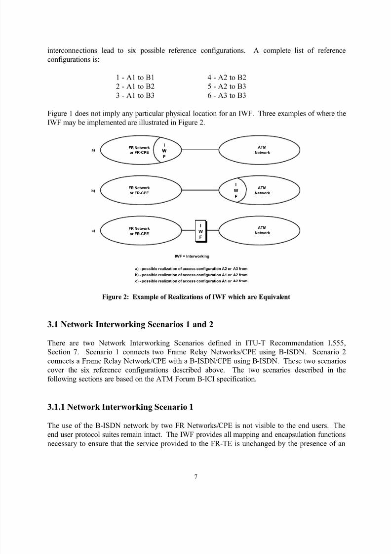
Figure 1 does not imply any particular physical location for an IWF. Three examples of where the
IWF may be implemented are illustrated in Figure 2.
I
W
F
I
W
F
I
W
F
FR Network
or FR-CPE
FR Network
or FR-CPE
FR Network
or FR-CPE
ATM
Network
ATM
Network
ATM
Network
IWF = Interworking
c)
b)
a)
a) - possible realization of access configuration A2 or A3 from
b) - possible realization of access configuration A1 or A2 from
c) - possible realization of access configuration A1 or A2 from
Figure 2: Example of Realizations of IWF which are Equivalent
3.1 Network Interworking Scenarios 1 and 2
There are two Network Interworking Scenarios defined in ITU-T Recommendation I.555,
Section 7. Scenario 1 connects two Frame Relay Networks/CPE using B-ISDN. Scenario 2
connects a Frame Relay Network/CPE with a B-ISDN/CPE using B-ISDN. These two scenarios
cover the six reference configurations described above. The two scenarios described in the
following sections are based on the ATM Forum B-ICI specification.
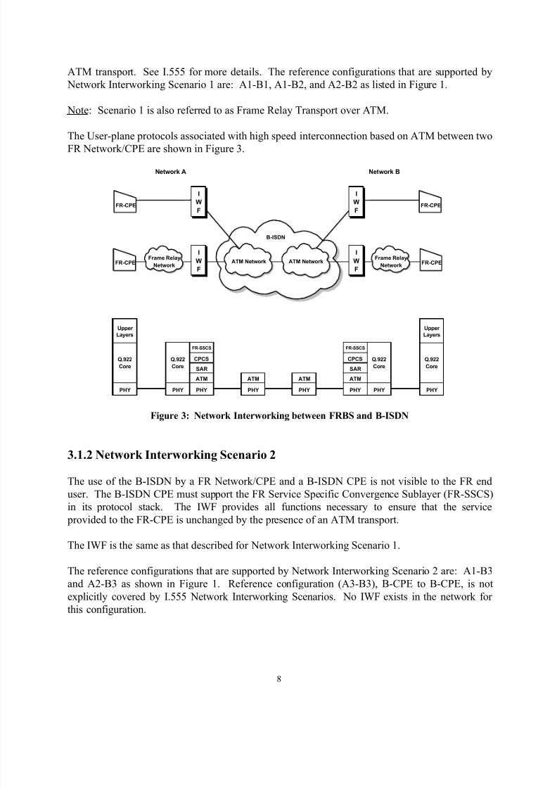
3.1.1 Network Interworking Scenario 1
The use of the B-ISDN network by two FR Networks/CPE is not visible to the end users. The
end user protocol suites remain intact. The IWF provides all mapping and encapsulation functions
necessary to ensure that the service provided to the FR-TE is unchanged by the presence of an
8/18/2019 frf.5
http://slidepdf.com/reader/full/frf5 8/19
8
ATM transport. See I.555 for more details. The reference configurations that are supported by
Network Interworking Scenario 1 are: A1-B1, A1-B2, and A2-B2 as listed in Figure 1.
Note: Scenario 1 is also referred to as Frame Relay Transport over ATM.
The User-plane protocols associated with high speed interconnection based on ATM between twoFR Network/CPE are shown in Figure 3.
ATM Network ATM Network
I
W
F
I
W
F
I
W
F
I
W
F
Frame Relay
Network
Frame Relay
NetworkFR-CPE FR-CPE
B-ISDN
FR-CPE FR-CPE
Network A Network B
PHY
Upper
Layers
Q.922
Core
PHY
Upper
Layers
Q.922
Core
PHY
Q.922
Core
PHY
Q.922
Core
PHY
ATM
SAR
CPCS
FR-SSCS
PHY
ATM
SAR
CPCS
FR-SSCS
PHY
ATM
PHY
ATM
Figure 3: Network Interworking between FRBS and B-ISDN
3.1.2 Network Interworking Scenario 2
The use of the B-ISDN by a FR Network/CPE and a B-ISDN CPE is not visible to the FR end
user. The B-ISDN CPE must support the FR Service Specific Convergence Sublayer (FR-SSCS)
in its protocol stack. The IWF provides all functions necessary to ensure that the service
provided to the FR-CPE is unchanged by the presence of an ATM transport.
The IWF is the same as that described for Network Interworking Scenario 1.
The reference configurations that are supported by Network Interworking Scenario 2 are: A1-B3
and A2-B3 as shown in Figure 1. Reference configuration (A3-B3), B-CPE to B-CPE, is not
explicitly covered by I.555 Network Interworking Scenarios. No IWF exists in the network for
this configuration.
8/18/2019 frf.5
http://slidepdf.com/reader/full/frf5 9/19
9
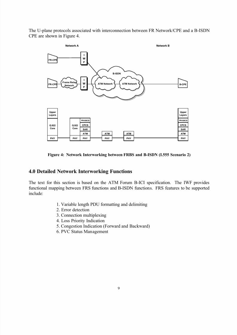
The U-plane protocols associated with interconnection between FR Network/CPE and a B-ISDN
CPE are shown in Figure 4.
ATM Network ATM Network
I
W
F
I
WF
Frame Relay
NetworkFR-CPE B-CPE
B-ISDN
FR-CPE
Network A Network B
PHY
Upper
Layers
Q.922
Core
PHY
Upper
Layers
PHY
Q.922
Core
PHY
ATM
SAR
CPCS
FR-SSCS
PHY
ATM
PHY
ATM ATM
SAR
CPCS
FR-SSCS
Figure 4: Network Interworking between FRBS and B-ISDN (I.555 Scenario 2)
4.0 Detailed Network Interworking Functions
The text for this section is based on the ATM Forum B-ICI specification. The IWF provides
functional mapping between FRS functions and B-ISDN functions. FRS features to be supported
include:
1. Variable length PDU formatting and delimiting
2. Error detection
3. Connection multiplexing
4. Loss Priority Indication
5. Congestion Indication (Forward and Backward)
6. PVC Status Management
8/18/2019 frf.5
http://slidepdf.com/reader/full/frf5 10/19
10
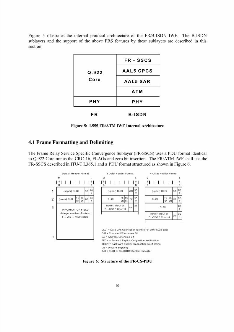
Figure 5 illustrates the internal protocol architecture of the FR/B-ISDN IWF. The B-ISDN
sublayers and the support of the above FRS features by these sublayers are described in this
section.
Q .922
Core
P HY P H Y
ATM
AAL5 SAR
AAL5 CPCS
FR - SSCS
B-ISDNF R
Figure 5: I.555 FR/ATM IWF Internal Architecture
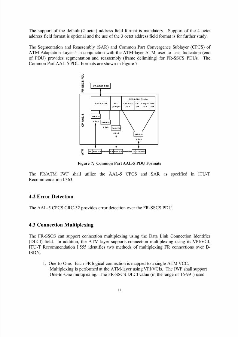
4.1 Frame Formatting and Delimiting
The Frame Relay Service Specific Convergence Sublayer (FR-SSCS) uses a PDU format identical
to Q.922 Core minus the CRC-16, FLAGs and zero bit insertion. The FR/ATM IWF shall use the
FR-SSCS described in ITU-T I.365.1 and a PDU format structured as shown in Figure 6.
1
2
3
n
M
S
B
M
S
B
M
S
B
L
S
B
L
S
B
L
S
B
Default Header Format 3 Octet Header Format 4 Octet Header Format
INFORMATION FIELD
(integer number of octets:
1 ... 262 ... 1600 octets)
(upper) DLCI
(lower) DLCI
C/REA
0
EA
1DE
BE
CN
FE
CN
C/REA
0
EA
0DE
EA
1D/C
BE
CN
FE
CN
(upper) DLCI
DLCI
(lower) DLCI or
DL-CORE Control
(upper) DLCI C/REA
0
EA
0DE
EA
0
EA
1D/C
DLCIBE
CN
FE
CN
DLCI
(lower) DLCI or
DL-CORE Control
DLCI = Data Link Connection Identifier (10/16/17/23 bits)
C/R = Command/Response Bit
EA = Address Extension Bit
FECN = Forward Explicit Congestion Notification
BECN = Backward Explicit Congestion Notification
DE = Discard Eligibility
D/C = DLCI or DL-CORE Control Indicator
Figure 6: Structure of the FR-CS-PDU
8/18/2019 frf.5
http://slidepdf.com/reader/full/frf5 11/19
11
The support of the default (2 octet) address field format is mandatory. Support of the 4 octet
address field format is optional and the use of the 3 octet address field format is for further study.
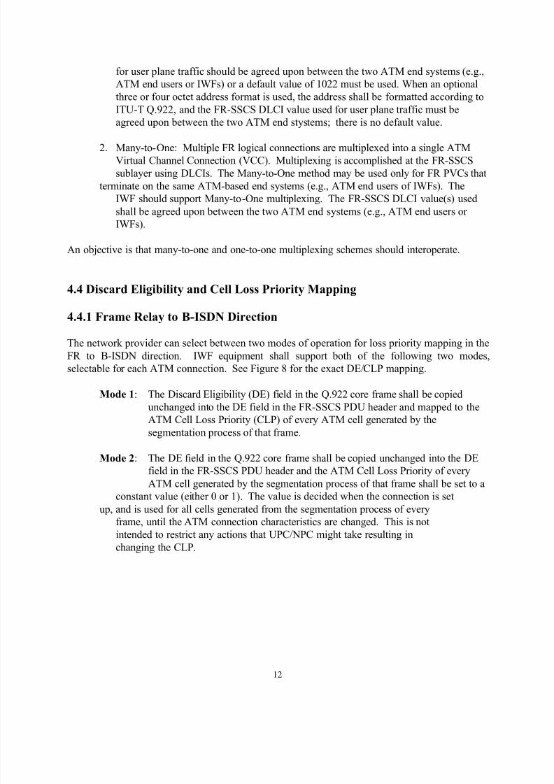
The Segmentation and Reassembly (SAR) and Common Part Convergence Sublayer (CPCS) of
ATM Adaptation Layer 5 in conjunction with the ATM-layer ATM_user_to_user Indication (end
of PDU) provides segmentation and reassembly (frame delimiting) for FR-SSCS PDUs. TheCommon Part AAL-5 PDU Formats are shown in Figure 7.
CPCS S DU PAD
(0-47)x8
CPCS-PDU Trailer
CPCS-UU
1x 8
CP I
1x 8
Length
2x 8
CR C
4x 8
FR-SSCS PDU
F R - S S C S P D U
C P - A A L - 5
A T M
SAR-PDU
SAR-PDU
SAR-PDU
SAR-PDU
4 8x8
4 8x8
4 8x8
4 8x8
ATM-SDUCH ATM-SDUCH ATM-SDUCH
Figure 7: Common Part AAL-5 PDU Formats
The FR/ATM IWF shall utilize the AAL-5 CPCS and SAR as specified in ITU-T
Recommendation I.363.
4.2 Error Detection
The AAL-5 CPCS CRC-32 provides error detection over the FR-SSCS PDU.
4.3 Connection Multiplexing
The FR-SSCS can support connection multiplexing using the Data Link Connection Identifier(DLCI) field. In addition, the ATM layer supports connection multiplexing using its VPI/VCI.
ITU-T Recommendation I.555 identifies two methods of multiplexing FR connections over B-
ISDN.
1. One-to-One: Each FR logical connection is mapped to a single ATM VCC.
Multiplexing is performed at the ATM-layer using VPI/VCIs. The IWF shall support
One-to-One multiplexing. The FR-SSCS DLCI value (in the range of 16-991) used
8/18/2019 frf.5
http://slidepdf.com/reader/full/frf5 12/19
12
for user plane traffic should be agreed upon between the two ATM end systems (e.g.,
ATM end users or IWFs) or a default value of 1022 must be used. When an optional
three or four octet address format is used, the address shall be formatted according to
ITU-T Q.922, and the FR-SSCS DLCI value used for user plane traffic must be
agreed upon between the two ATM end stystems; there is no default value.
2. Many-to-One: Multiple FR logical connections are multiplexed into a single ATM
Virtual Channel Connection (VCC). Multiplexing is accomplished at the FR-SSCS
sublayer using DLCIs. The Many-to-One method may be used only for FR PVCs that
terminate on the same ATM-based end systems (e.g., ATM end users of IWFs). The
IWF should support Many-to-One multiplexing. The FR-SSCS DLCI value(s) used
shall be agreed upon between the two ATM end systems (e.g., ATM end users or
IWFs).
An objective is that many-to-one and one-to-one multiplexing schemes should interoperate.
4.4 Discard Eligibility and Cell Loss Priority Mapping
4.4.1 Frame Relay to B-ISDN Direction
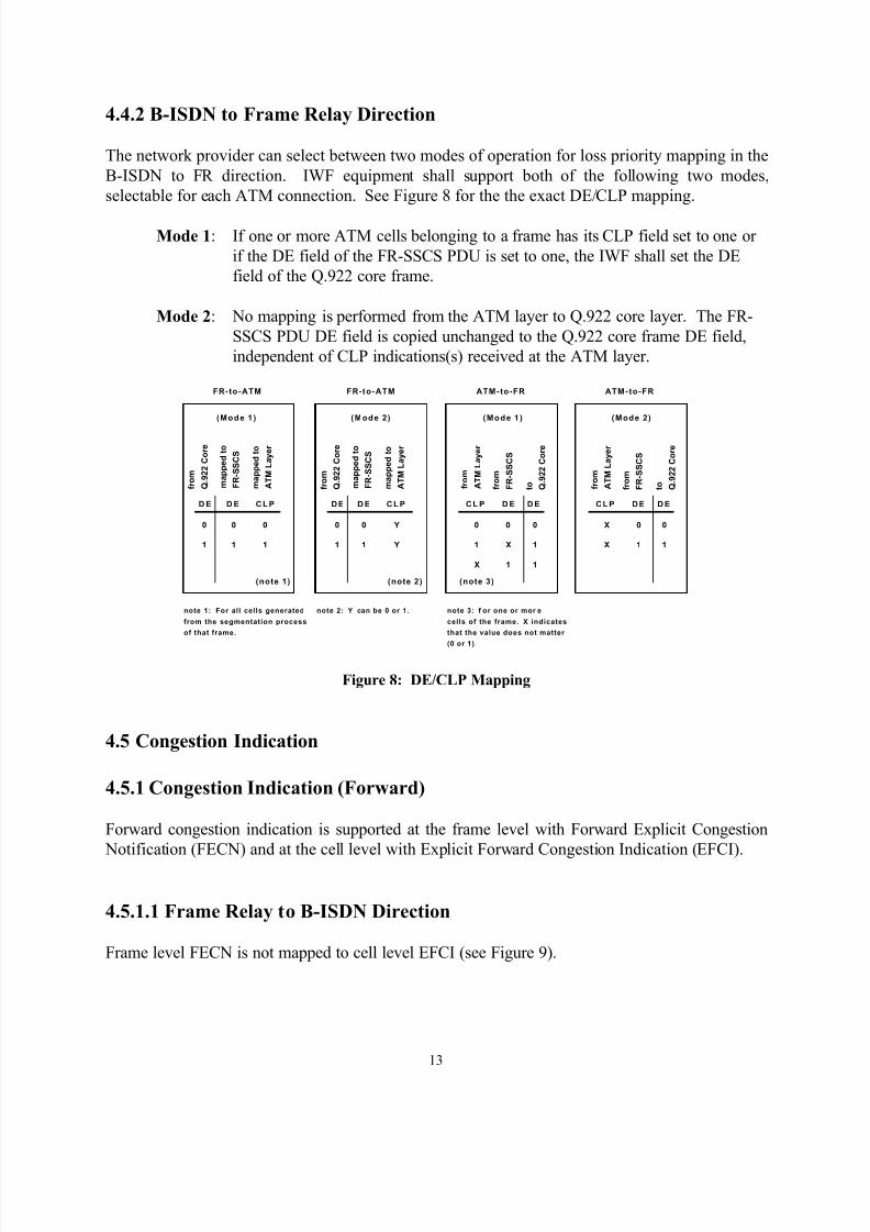
The network provider can select between two modes of operation for loss priority mapping in the
FR to B-ISDN direction. IWF equipment shall support both of the following two modes,
selectable for each ATM connection. See Figure 8 for the exact DE/CLP mapping.
Mode 1: The Discard Eligibility (DE) field in the Q.922 core frame shall be copied
unchanged into the DE field in the FR-SSCS PDU header and mapped to theATM Cell Loss Priority (CLP) of every ATM cell generated by the
segmentation process of that frame.
Mode 2: The DE field in the Q.922 core frame shall be copied unchanged into the DE
field in the FR-SSCS PDU header and the ATM Cell Loss Priority of every
ATM cell generated by the segmentation process of that frame shall be set to a
constant value (either 0 or 1). The value is decided when the connection is set
up, and is used for all cells generated from the segmentation process of every
frame, until the ATM connection characteristics are changed. This is not
intended to restrict any actions that UPC/NPC might take resulting in
changing the CLP.
8/18/2019 frf.5
http://slidepdf.com/reader/full/frf5 13/19
13
4.4.2 B-ISDN to Frame Relay Direction
The network provider can select between two modes of operation for loss priority mapping in the
B-ISDN to FR direction. IWF equipment shall support both of the following two modes,
selectable for each ATM connection. See Figure 8 for the the exact DE/CLP mapping.
Mode 1: If one or more ATM cells belonging to a frame has its CLP field set to one or
if the DE field of the FR-SSCS PDU is set to one, the IWF shall set the DE
field of the Q.922 core frame.
Mode 2: No mapping is performed from the ATM layer to Q.922 core layer. The FR-
SSCS PDU DE field is copied unchanged to the Q.922 core frame DE field,
independent of CLP indications(s) received at the ATM layer.
D E D E D E D ED E C L P D E C L P D EC L P D EC L P
0 0 0
1 1 1
(note 1)
(Mode 1 ) (Mode 1 )(Mode 2) (Mode 2)
0 0 Y
1 1 Y
(note 2)
0 0
1 X
0
1
(note 3)
X 1 1
X 0
X 1
0
1
FR-to-ATM FR-to-ATM ATM-to-FR ATM-to-FR
f r o m
Q . 9 2 2 C o r e
m a p p e d t o
F R - S S C S
m a p p e d t o
A T M L a y e r
f r o m
Q . 9 2 2 C o r e
m a p p e d t o
F R - S S C S
m a p p e d t o
A T M L a y e r
f r o m
A T M L a y e r
t o Q . 9 2 2 C o r e
f r o m
F R - S S C S
f r o m
A T M L a y e r
t o Q . 9 2 2 C o r e
f r o m
F R - S S C S
note 1: For all cells generated
from the segmentation process
of that frame.
note 2: Y can be 0 or 1. note 3: f or one or mor e
cells of the frame. X indicates
that the value does not matter
(0 or 1).
Figure 8: DE/CLP Mapping
4.5 Congestion Indication
4.5.1 Congestion Indication (Forward)
Forward congestion indication is supported at the frame level with Forward Explicit Congestion
Notification (FECN) and at the cell level with Explicit Forward Congestion Indication (EFCI).
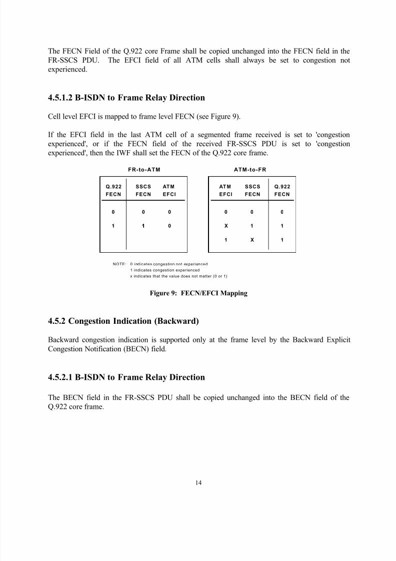
4.5.1.1 Frame Relay to B-ISDN Direction
Frame level FECN is not mapped to cell level EFCI (see Figure 9).
8/18/2019 frf.5
http://slidepdf.com/reader/full/frf5 14/19
14
The FECN Field of the Q.922 core Frame shall be copied unchanged into the FECN field in the
FR-SSCS PDU. The EFCI field of all ATM cells shall always be set to congestion not
experienced.
4.5.1.2 B-ISDN to Frame Relay Direction
Cell level EFCI is mapped to frame level FECN (see Figure 9).
If the EFCI field in the last ATM cell of a segmented frame received is set to 'congestion
experienced', or if the FECN field of the received FR-SSCS PDU is set to 'congestion
experienced', then the IWF shall set the FECN of the Q.922 core frame.
Q.922
FECN
Q.922
FECN
FR-to-ATM ATM-to-FR
SSCS
FECN
ATM
EFCI
AT M
EFCI
SSCS
FECN
0 0 0
1 1 0
0 0
X 1
0
1
1 X 1
1
NOTE: 0 indicates congestion not experienced
1 indicates congestion experienced
x indicates that the value does not matter (0 or 1)
Figure 9: FECN/EFCI Mapping
4.5.2 Congestion Indication (Backward)
Backward congestion indication is supported only at the frame level by the Backward Explicit
Congestion Notification (BECN) field.
4.5.2.1 B-ISDN to Frame Relay Direction
The BECN field in the FR-SSCS PDU shall be copied unchanged into the BECN field of the
Q.922 core frame.
8/18/2019 frf.5
http://slidepdf.com/reader/full/frf5 15/19
15
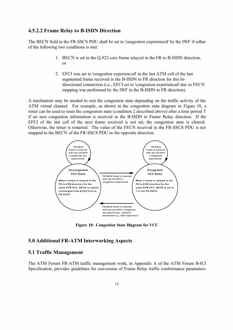
4.5.2.2 Frame Relay to B-ISDN Direction
The BECN field in the FR-SSCS PDU shall be set to 'congestion experienced' by the IWF if either
of the following two conditions is met:
1. BECN is set in the Q.922 core frame relayed in the FR to B-ISDN direction,or
2. EFCI was set to 'congestion experienced' in the last ATM cell of the last
segmented frame received in the B-ISDN to FR direction for this bi-
directional connection (i.e., EFCI set to 'congestion experienced' due to FECN
mapping was performed by the IWF in the B-ISDN to FR direction).
A mechanism may be needed to exit the congestion state depending on the traffic activity of the
ATM virtual channel. For example, as shown in the congestion state diagram in Figure 10, a
timer can be used to reset the congestion state (condition 2 described above) after a time period T
if no new congestion information is received in the B-ISDN to Frame Relay direction. If theEFCI of the last cell of the next frame received is not set, the congestion state is cleared.
Otherwise, the timer is restarted. The value of the FECN received in the FR-SSCS PDU is not
mapped to the BECN of the FR-SSCS PDU in the opposite direction.
FR-SSCS
Frame is received
with last cell EFCI
= congestion not
experienced
FR-SSCS
Frame is received
with last cell EFCI
= congestion
experienced
FR-SSCS Frame is received
with last cell EFCI =
congestion experienced
FR-SSCS Frame is received
with last cell EFCI = congestion
not experienced. (optional
mechanism e.g., timer expiration.)
When a frame is relayed in the
FR to ATM direction for the
same ATM VCC, BECN is copied
unchanged from Q.922 Core to
FR-SSCS.
Uncongested
VCC State
Congested
VCC State
When a frame is relayed in the
FR to ATM direction for the
same ATM VCC, BECN is set to
1 in the FR-SSCS.
Figure 10: Congestion State Diagram for VCC
5.0 Additional FR-ATM Interworking Aspects
5.1 Traffic Management
The ATM Forum FR-ATM traffic management work, in Appendix A of the ATM Forum B-ICI
Specification, provides guidelines for conversion of Frame Relay traffic conformance parameters
8/18/2019 frf.5
http://slidepdf.com/reader/full/frf5 16/19
16
(Throughput, Committed Burst Size, Excess Burst Size, Access Rate) to ATM traffic
conformance parameters (PCR, CDV, SCR, MBS) using the GCRA (Generic Cell Rate
Algorithm) configurations for Frame Relay interworking described in Examples 2a and 2b of
section 3.6 of the ATM UNI Specification version (3.0).
The ATM traffic conformance parameter determination guidelines from Frame Relay trafficconformance parameters for one-to-one mapping, as described in Appendix A of the ATM Forum
B-ICI Specification shall be used by network providers for FR-ATM Interworking traffic
management. Two methods are provided in the appendix for determination of ATM traffic
conformance parameters from Frame Relay traffic conformance parameters. The first method
provides accurate representation of FR traffic parameters in an ATM network. The selection of
one of the two methods shall be decided by bilateral agreement between networks.
5.2 PVC Management
The text for this section is based on the ATM Forum B-ICI specification. The management of the
ATM layer and the FR PVC Status Management of the FR-SSCS layer can operateindependently. Each layer has its own responsibility for the layer management (e.g., some
functions of the management in the ATM layer will be performed by usage of the OAM cell
flows). The PVC status from the ATM Layer shall be used by the FR-SSCS layer when
determining the status of the FR PVCs.
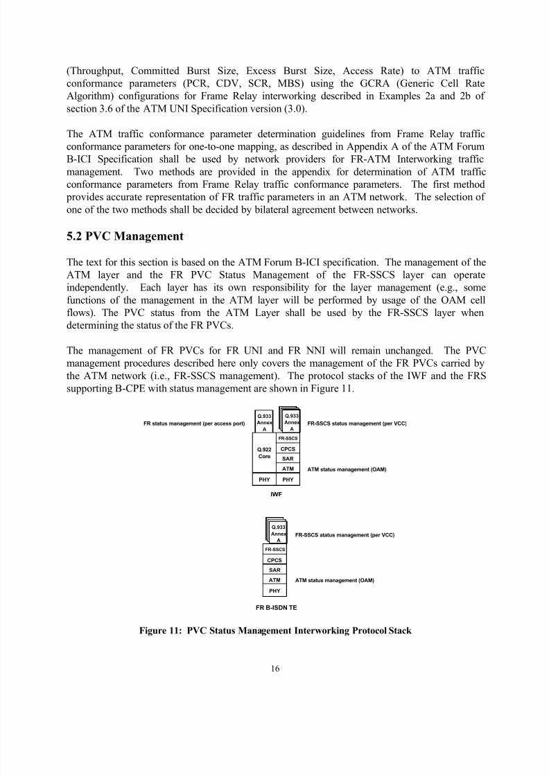
The management of FR PVCs for FR UNI and FR NNI will remain unchanged. The PVC
management procedures described here only covers the management of the FR PVCs carried by
the ATM network (i.e., FR-SSCS management). The protocol stacks of the IWF and the FRS
supporting B-CPE with status management are shown in Figure 11.
PHY
Q.922
Core
PHY
ATM
SAR
CPCS
FR-SSCS
Q.933
Annex
A
Q.933
Annex
A
Q.933
Annex
A
Q.933
Annex
A
PHY
ATM
SAR
CPCS
FR-SSCS
Q.933
Annex
A
Q.933
Annex
A
Q.933
Annex
A
IWF
FR B-ISDN TE
FR-SSCS status management (per VCC)
ATM status management (OAM)
FR status management (per access port)
FR-SSCS atatus management (per VCC)
ATM status management (OAM)
Figure 11: PVC Status Management Interworking Protocol Stack
8/18/2019 frf.5
http://slidepdf.com/reader/full/frf5 17/19
17
The management of the FR-SSCS layer shall be performed by bi-directional (symmetric) PVC
management procedures adopted from the ITU-T Recommendation Q.933 Annex A. Selection of
specific options within the Q.933 Annex A shall be aligned with FRF.2 - Frame Relay Network-
to-Network Interface Implementation Agreement.
Note: This applies for the B-CPE emulating FR (Figure 1). This allows all six connection
possibilities of Figure 1 including the A3 to B3 case.
For FR PVC Status Management of FR connection(s) carried by an ATM VCC, DLCI = 0 is used
to exchange PVC status management between IWF(s) and/or B-CPE emulating FR.
In the case of one-to-one multiplexing, the procedures described in ITU-T Q.933
Recommendation Annex A apply with the following changes:
1. The N391 Full Status Polling counter default is set to 1.
2. The T391 Link Integrity Verification Polling timer and the T392 Polling Verification
timer default values are set to 180 and 200 seconds respectively.
3. The use of the Frame Relay asynchronous message as specified in Q.933 Annex A
is recommended.
Link Integrity Verification of ATM VCCs is provided by ATM OAM F5 flows. The ATM VCC
status obtained by the OAM F5 flow is conveyed to the Q.933 Annex A entity.
5.3 Description of Upper Layer User Protocol Encapsulation Methods
Higher-layer protocols may be conveyed between TEs using the Frame Relay Forum
Multiprotocol Encapsulation Implementation Agreement (FRF.3). Multiprotocol encapsulation
procedures shall be used only when explicitly configured or agreed during connection
establishment.
The Frame Relay Forum Multiprotocol Encapsulation Implementation Agreement is based on
IETF RFC 1490 and ANSI T1.617a Annex F. The key element of this method is the
identification of the encapsulated higher-layer protocol using NLPID (Network Layer Protocol
ID, as defined in ISO/IEC TR 9577). This method has been adopted for encapsulation over
Frame Relay.
The B-TE has to implement NLPID encapsulation when using ATM-FR network interworking.
The Frame Relay TE implements NLPID encapsulation.
8/18/2019 frf.5
http://slidepdf.com/reader/full/frf5 18/19
18
5.4 Operations and Maintenance
The text for this section is based on the ATM Forum B-ICI specification. This Section provides
the AAL Type 5 operations above the ATM layer. Operations for layers above the AAL are not
discussed in this Version. Section 5.4.1 discusses operations for the common part of the AALType 5.
5.4.1 Operations for the Common Part of the AAL Type 5
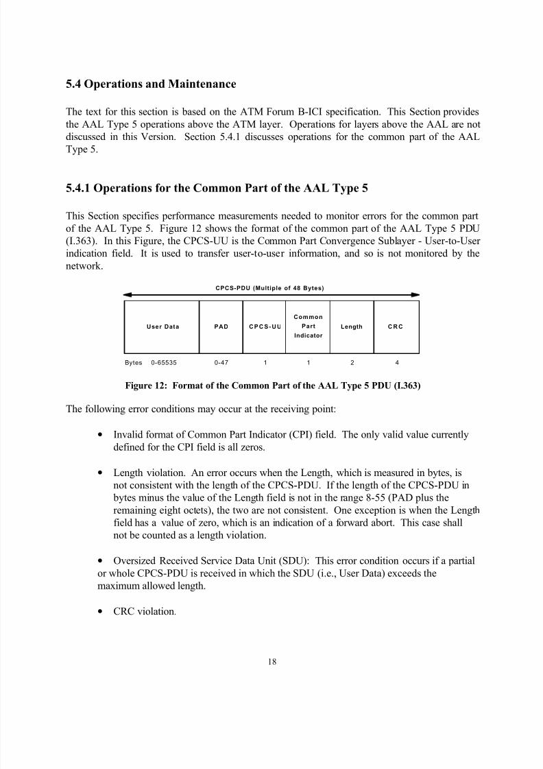
This Section specifies performance measurements needed to monitor errors for the common part
of the AAL Type 5. Figure 12 shows the format of the common part of the AAL Type 5 PDU
(I.363). In this Figure, the CPCS-UU is the Common Part Convergence Sublayer - User-to-User
indication field. It is used to transfer user-to-user information, and so is not monitored by the
network.
User Data PAD CPCS- UU
Common
Part
Indicator
Length C R C
CPCS-PDU (Multiple of 48 Bytes)
Bytes 0-65535 0-47 1 1 2 4
Figure 12: Format of the Common Part of the AAL Type 5 PDU (I.363)
The following error conditions may occur at the receiving point:
• Invalid format of Common Part Indicator (CPI) field. The only valid value currently
defined for the CPI field is all zeros.
• Length violation. An error occurs when the Length, which is measured in bytes, is
not consistent with the length of the CPCS-PDU. If the length of the CPCS-PDU in
bytes minus the value of the Length field is not in the range 8-55 (PAD plus the
remaining eight octets), the two are not consistent. One exception is when the Length
field has a value of zero, which is an indication of a forward abort. This case shall
not be counted as a length violation.
• Oversized Received Service Data Unit (SDU): This error condition occurs if a partial
or whole CPCS-PDU is received in which the SDU (i.e., User Data) exceeds the
maximum allowed length.
• CRC violation.

8/18/2019 frf.5
http://slidepdf.com/reader/full/frf5 19/19
19
• If the receiving entity implements a reassembly timer (which is optional, as specified
in I.363), then the number of timer expirations shall be counted.
Network equipment at a B-ICI terminating the AAL Type 5 common part shall count the
occurrences of the listed errors at the receiving point.
A typical value for a measurement interval could be fifteen minutes, and a least eight hours of
history should be kept. The measurement interval and amount of history data will be established
by bilateral agreements between carriers.


![Exercices et études pour la harpe : op. 9 · 2019. 6. 7. · (ex.l) i t r f r. rfrfrf.rfrfrfr-frf . pour les ex. ecrits en ^ binaires] pour les ex, ecrits en triolets!] Les differents](https://img.pdfslide.fr/doc/110x75/6145155034130627ed50c25d/exercices-et-tudes-pour-la-harpe-op-9-2019-6-7-exl-i-t-r-f-r-rfrfrfrfrfrfr-frf.jpg)


![8og k |flws/0f · 2020. 7. 8. · #=( b/vf:t kmf/fdsf] 9f Frf ===== !* #=(-s_ pDd]bjf/sf ] pd ]/sf ] lgwf {/0f ===== !* #=(-v_ b/vf:t pk/ 5fglag ug]{ ===== !* #=(-u_ b/vf:t :jLs[t](https://img.pdfslide.fr/doc/110x75/60cbb0e73605d82a82329d15/8og-k-flws0f-2020-7-8-bvft-kmffdsf-9f-frf-s-pddbjfsf.jpg)