Embed Size (px)
Citation preview
INFORMATION TO USERS
This manuscript has been reproduced trom the microfilm master. UMI films
the text directty trom the original or copy submitted. Thus, some thesis and
dissertation copies are in typewriter face. while others may be trom any type of
computer printer.
Th. quallty of thl. reproduction i. dependent upon the quallty of the
copy submitted. Broken or indistinct print, colored or poor quality illustrations
and photographs, print bleedthrough. substandard margins, and improper
alignment can adversely affect reproduction.
ln the unlikely event that the author did not send UMI a complete manuscript
and there are missing pages, these will be noted. Also. if unauthorized
copyright material had to be removed. a note will indicate the deletion.
Oversize materials (e.g., maps. drawings, charts) are reproduced by
sectioning the original, beginning at the upper left·hand corner and continuing
trom left to right in equal sections with small overlaps.
Proauest Information and Leaming300 North 2eeb Raad. Ann Arbor, MI 48106·1346 USA
aQO-S21-Q600

The Nature and Origins of Caldera Structure and Morphology, using• Results from Analogue Modeling
By
Ben Kennedy
A thesis submitted to the Faculty ofGraduate Studies and Research in partial
fulfillment of the requirementsfor the degree of Master of Science
Department ofEarth and Planetary SciencesMcGill University, Montreal
© Ben Kennedy, 2000
14'1 NationallibraryofCaMda
~nationale
~u~and Acquilitions etBibliographie Services .1'Vices bibliographiques
315W"lIIg1Dnar-t _ ....W...agb,e.-ON K1A0N4 c...ON K1A0N4CIMda c..da
The author bas granted a DOD
exclusive licence aIloWÏDg theNatioaal Library ofCanada tareproduce, loau, distribute or seOcopies ofdûs thesis in microfonn,paper or electroDic formats.
The author retaiDs ownersbip ofthecopyright in tbis thesis. Neither thetbesis nor substantial extracts ftom itmay be printed or otherwisereproduced without the autbor'spermission.
L'aule. a accordé une licence nonexclusive pennettant à laBibliothèque uatiouale du Canada dereproduire, prêter, distribuer ouvendre des copies de cette thèse sousla forme de microfiche/film, dereproduction sur papier ou sur formatélectronique.
L'auteur conserve la propriété dudroit d'auteur qui protège cette thèse.Ni la thèse Di des exlraits substantielsde celle-ci ne doivent être imprimésou autrement reproduits sans sonautorisation.
0-612-70723-7
•
•
ii
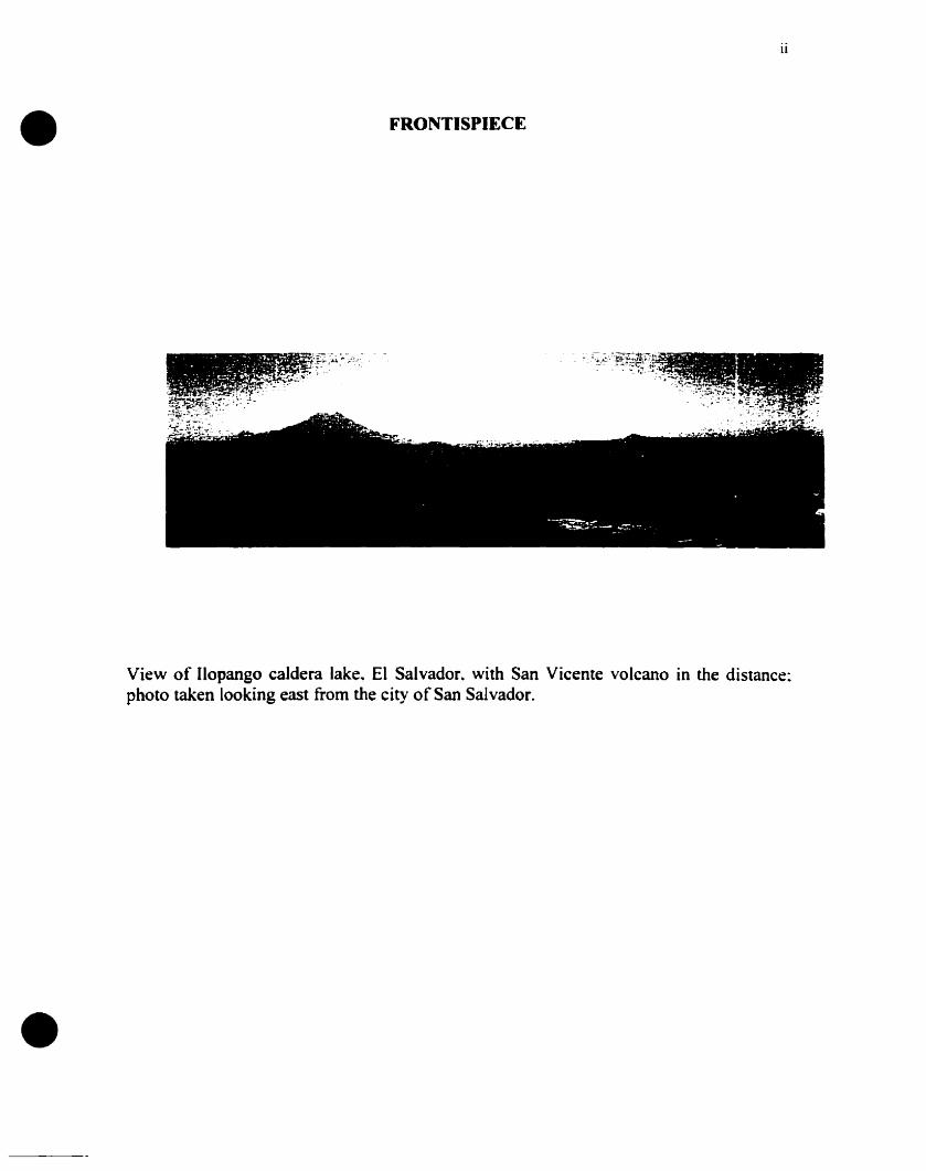
FRONTISPIECE
View of Il0 pango caldera lake. El Salvador. with San Vicente volcano in the distance:photo taken looking east from the city of San Salvador.
•
•
iii
ABSTRACT
Calderas illustrate a variety of different styles \vhich are controlled by their
internaI structure and morphology. The internaI structure of many calderas is not
exposed; as a result~ the calderas frequently are interpreted as simple pistons. The results
and examples from this thesis indicate that caldera structure is often more complex than
this and that caldera formation consists of severa! stages controlled by complex
interactions of many variables. InternaI processes and parameters include rock propenies
(shear strength~ planes of weakness. venical and horizontal variations). dimensions and
internai pressure of the associated magma chamber. styles of tumescence and resurgence.
and the size of the eruption. Extemal processes and parameters are also imponant. such
as the regional stress regime (e.g.. extensional and pull-apan basins).. pre-existing
topography~ and pre-existing structures (e.g .. regional faults~ basement grain).
Scaled physical models of caldera formation were carried out to investigate the
effects of sorne of these variables on the temporal development of calderas. Dry sand
contained in a 1 m-diameter cylinder was used as an analogue of crustal rocks. and a
water-filled 60 cm-diameter rubber bladder was used as an analogue for a magma
chamber. Scaling parameters used were a length ratio (L*) of 2.5 x 10⁻⁵ and a stress ratio
(cr *) of 2.0 x 10os.The collapse process was initiated by withdrawing water from the
bladder at a rate of 1600 cm) min°·. The depth of the rubber bladder then was varied from
6.0 to 24 cm to simulate different magma chamber depths (2.4-9.6 km). The pressure
within the bladder also was varied by changing the initial volume of water in the bladder
from 40 to 45 liters before evacuation. The effects of different surface topograph~ prillr
to collapse also were investigated by building scaled ridges. mountain ranges. and
stratocone volcanoes. and positioning them in different positions and orientations aho\"e
the bladder. Experiments also were carried out with the rubber bladder tilted to promote
asymmetric collapse.
Generally. defonnation began with broad sagging. then an arcuate or linear
outward dipping fault formed on one side of the caldera. This fault propagated laterally
around the caldera in both directions and sometimes joined up with other faults. forming
• a polygonal caldera. As subsidence continued~ the caldera grew incrementally outwards.
progressively forming a series of concentric subsidence-controlling faults. Lastly. a
peripheral zone of downsagging would develop. bounded by an inward dipping outer
fault related to extension. As the depth of the bladder was increased. (1) the volume of
the caldera decreased. (2) the area of faulting decreased. (3) the symmetry of the caldera
was affected and (4) the coherence of the subsiding block decreased. With greater
topographie relief. (1) the volume of the resultant caldera increased. (2) single ring
fractures became larger and more coherent. and (3) the caldera was more prone to
slumping. The location of the topographie relief in relation to the bladder did not appear
to affect the symmetry of subsidence. As the initial volume and internai pressure of the
bladder was decreased. (1) the resultant caldera had a larger volume. and (2) faults were
initiated earlier. When the bladder was tilted. subsidence was highly asymmetric: tàults
formed first where the bladder was shallowest. Subsidence then shifted rapidly to where
the bladder was deepest. producing an elongate trapdoor caldera which was deepest
where the bladder was deepest.
•
•
•
v
RESUME
Les calderas démontrent une variété de styles différents qui sont contrôlés par leur
structure ainsi que leur morphologie internes. La structure interne de plusieurs calderas
n ~est pas exposée~ par conséquent~ les calderas sont fréquemment interprétées comme de
simples pistons. Les résultats et les exemples de cette thèse indiquent que la structure
d ~ une caldera est souvent plus complexe qu'un simple modèle de piston et que sa
formation consiste en plusieurs étapes contrôlées par des interactions complexes entre de
nombreuses variables.
Les processus internes incluent des paramètres comme les propriétés de la roche
(force de cisaillement~ plans de faiblesse. variations verticales et horizontales)~ les
dimensions et la pression interne de la chambre magmatique~ les styles de bombement et
de résurgence. et l'ampleur de l'éruption. Les processus extemes~ également importants.
comprennent les paramètres suivants: le régime de stress régional (par exemple. les
bassins d~extension et de transtension), la topographie pré-existante. et la structure pré
existante (par exemple. les failles régionales et la structure du socle).
Des modèles physiques à réchelle de la formation d'une caldera sont ici proposés
pour investiguer les effets de certaines variables sur le développement temporel des
calderas. Du sable sec contenu dans un cylindre de 1 mètre de diamètre a été utilisé
comme analogue de la roche de la croûte terrestre. et un ballon de caoutchouc de 60
centimètres de diamètre rempli d'eau tenait le rôle d'une chambre magmatique.
Les paramètres de calibration utilisés étaient un rapport de longueur (L*) de
2.5* 10-5 et un rapport de cisaillement (cr*) de 2.0.10-5• L'effondrement était initié par
l'évacuation de l'eau du ballon à un taux de 1600 cm3 min-l•
•
•
vi
Par la suite. la profondeur à laquelle le ballon était situé était \'ariée de 6.0 à 24
cm pour simuler la profondeur de différentes chambres magmatiques (2.4-9.6 km). La
pression à l'intérieur du ballon était également contrôlée en changeant le volume initial
d'eau dans le ballon de 40 à 45 litres avant révacuation.
Les effets de différentes topographies de surface précédent l'effondrement ont
aussi été étudiés en construisant des crêtes à r échelle, des chaines de montagnes, et des
stratovolcans, et en les positionnant dans différentes positions et orientations au·dessus
du ballon. Certaines expériences ont été réalisées avec le ballon incliné pour promouvoir
un effondrement asymétrique.
Généralement. la déformation commençait par un large affaissement. ensuite une
faille avec un pendage vers l'extérieur soit en arc soit linéaire se formait sur un des côtés
de la caldera. Cette faille se prolongeait latéralement autour de la caldera dans les deux
directions et parfois se joignait avec d'autres failles. formant une caldera polygonale. Au
tùr et à mesure que l'effondrement se poursuivait. [a caldera s'agrandissait vers
l'extérieur. formant progressivement une série de failles concentriques contrôlant
["affaissement. Finalement. une zone périphérique d'affaissement se développait.
délimitée par une faille à pendage vers l'intérieur reliée à r extension.
Lorsque la profondeur du ballon était augmentée. (1) le volume de la caldera
diminuait. (2) l'aire de failles diminuait. (3) Ifl symétrie de la caldera était affectée et (4)
la cohérence du bloc affaissant se réduisait. Avec un relief topographique plus prononçé.
(1) le volume de la caldera augmentait, (2) de simples fractures en anneaux devenaient
plus larges et plus cohérentes, et (3) la caldera avait plus tendance à s'effondrer.
•
•
vii
La disposition du relief topographique par rapport au ballon ne semblait pas
affecter la symétrie de l'affaissement. Lorsque le volume initial et la pression interne du
ballon était augmentés. (1) la caldera résultante avait un volume plus grand. et (2) des
failles se formaient plus tôt. Quand le ballon était incliné. l'affaissement était grandement
asymétrique. et les failles se fonnaient d'abord où le ballon était enfoui le moins creux.
L.affaissement se déplaçait ensuite rapidement où le ballon était enfoui le plus
profondément. produisant une caldera allongée en style de trappe qui était plus protonde
où le ballon était plus profond.
•
•
viii
AKNOWLEDGMENTS
Firstly and most importantly [ would like to thank my supervisor. Dr. John Stix.
for his constant support. assistance and enthusiasm during the experiments. fieldwork and
writing of the thesis. [ would also like to thank Dr. James Vallance and Dr. Andrew
Hynes for useful advice. discussions and helpful criticism~ Dr. Ronald Doig tor the use of
his laboratory and his continued interest and help throughout the experimental work: Yan
Lavallée for his dedication and enthusiasm during long weeks in the laboratory and the
field; Dr. A. E. Williams-Jones (Willy) and his research group for giving me a place to
work and for constant help with the computers; Mathieu Richer and Oliver Schatz for
help in the panic of putting together this thesis; Michel Demidoff for his assistance with
the figures in Chapter 1.
Financial support for this work was provided to me by funds from the Department
of Eanh and Planetary Sciences. McGill University. and from GEOTOP. Université du
Québec à MontréaL and by a research grant to J. Stix from the Natural Sciences and
Engineering Research Council ofCanada.
•
•
ix
T ABLE OF CONTENTS
FRONTISPIECE ii
ABSTRACT iii
RESUMÉ v
ACKNOWLEDGMENTS viii
TABLE OF CONTENTS ix
LIST OF FIGURES AND TABLES xii
PREFACE xviii
CHAPTER 1. INTRODUCTION Tû CALDERA FORMATION l
General Statement 1
Previous Work 4Theoretical studies of caldera formation 4Analogue models of subsidence 11
A Descriptive Outline of Caldera Types 16Simple piston 17Inward dipping piston 17Outward dipping piston 19Polygonal piston 19Downsag calderas 21Trapdoor calderas 23Concentric step-down calderas 23Chaotic calderas 25Rifted calderas 29Pull-apan calderas 29Piecemeal/ regional fault-controlled calderas 30
Stages in the Temporal Evolution of Calderas 33Stage 1. Magma chamber intrusion 33Stage 2. Initial emption and chamber evacuation 40Stage 3. Downsagging and the onset of subsidence .42Stage 4. Main subsidence and emption phase .45Stage 5. Eruption quiescence and peripheral extension 49Stage 6. Continued eruption. subsidence and change in eruptive style 51Stage 7. Resurgence and dome and flow extrusion 54
•
•
x
CHAPTER 2. AN EXPERIMENTAL SruDY Of CALDERA FORMATION .59
General Statement 59
Methodology 59Experimental setup 59Scaling of variables , 64
Relevance and Limitations 66
Results 68Depth 68Topography 76Pressure 79Tilted chamber 81General observations of experimental calderas 82
Interpretation of Results 83Temporal caldera development in plan view 83Temporal fault development in cross-section 86Downsagging and peripheral extension 88Controls on caldera morphology 92
Discussion , 108The nature and origin ofcaldera faults 108Downsagging , 114Resurgence 117Implications for styles of caJdera collapse 117
Conclusions 119
References 125
•
•
XI
LIST OF FIGURES AND TABLES
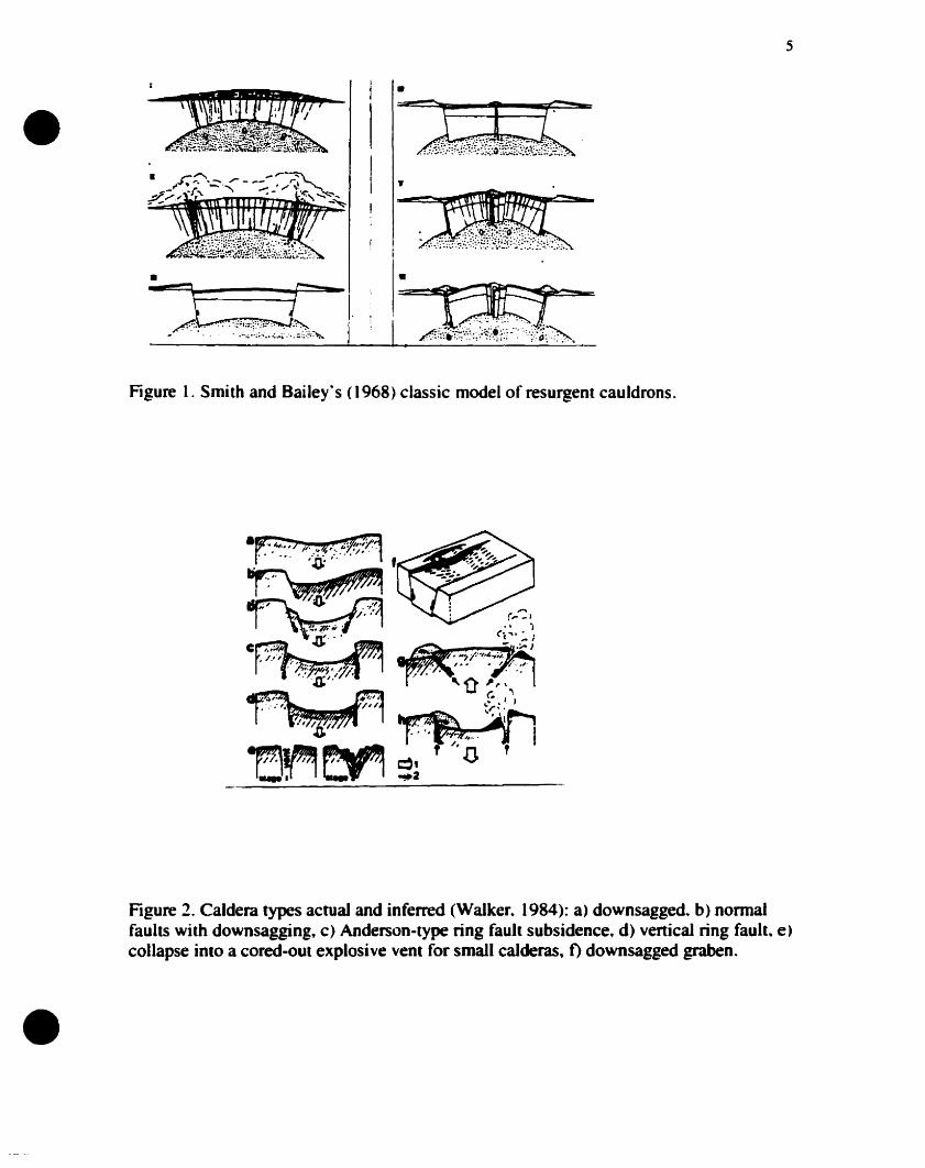
Figure l. Smith and Bailey's (1968) c1assic model of resurgent cauldrons 5
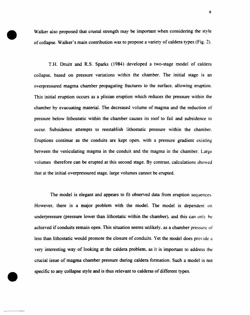
Figure 2. Caldera types actual and inferred (Walker. 1984): a) downsagged. b) normalfaults with downsagging. c) Anderson~type ring fault subsidence. d) vertical ring fault. e)collapse into a cored-out explosive vent for small calderas. f) downsagged graben 5
Figure 3. Three~dimensionai block diagram of piston collapse along vertical ring faults.with a baek~eroded topographie margin 18
Figure 4. a) Three-dimensional block diagram of piston collapse along inward dippingfaults; two eoncentric ring faults can be seen. b) An example from Suswa volcano.Gregory rift valley. Kenya (Skilling. 1993) 18
Figure 5. a) Three~dimensional bloek diagram of outward dipping piston col1apse with aperipheral area of normal fauIting. b) An example of earthquakes marking the ring fault.1983~1985. from Rabaul caldera. Papua New Guinea (Mori and McKee. 1987) 10
Figure 6. a) Three~dimensional block diagram of polygonal piston collapse. with linearsubsidence~controlling faults. b) An example from the Ossipee cauldron. New Hampshire(Kingsley. 1931) 10
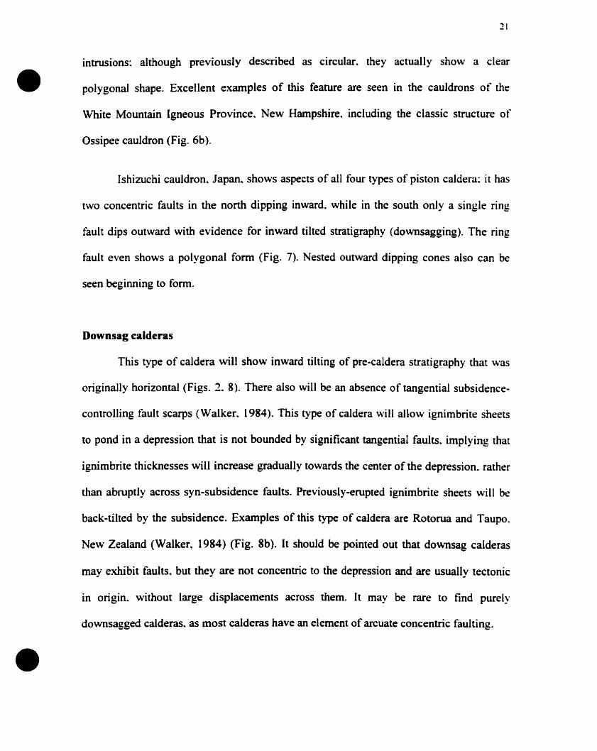
Figure 7. Temporal evolution of Ishizuchi cauldron. Japan (Yoshida. 1984). Thisstructure shows a combination of different styles of piston collapse. including subsidencealong both inward and outward dipping faults and a polygonal~shaped subsiding block.12
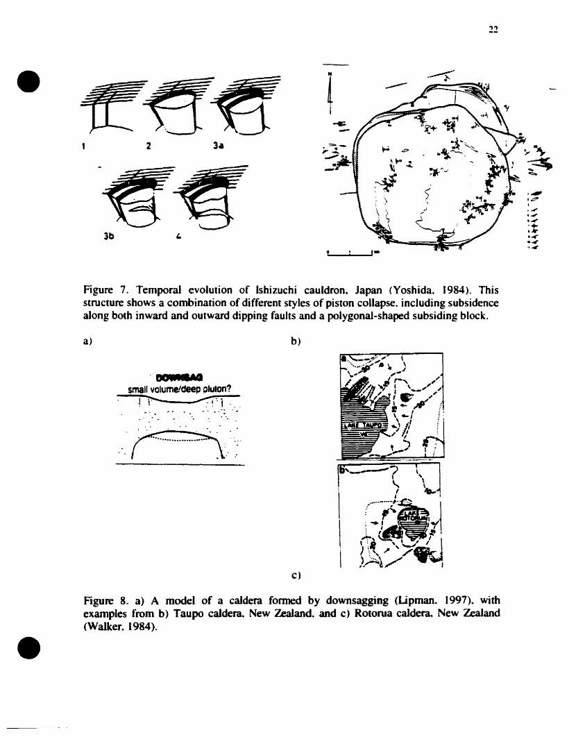
Figure 8. a) A model of a caldera formed by downsagging (Lipman. 1997). withexamples from b) Taupo caldera. New Zealand. and c) Rotorua caJdera. New Zealand(Walker. 1984) 11
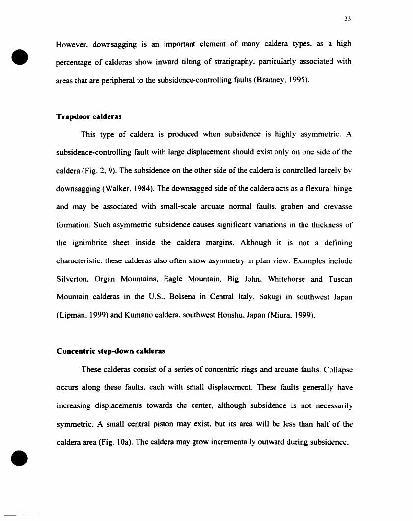
Figure 9. a) A model of a trapdoor-style caldera (Lipman. 1997). b) An example fromKumano caldera. southwest Honshu. Japan (Miura.. 1999) 14
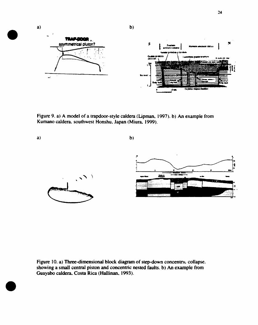
Figure 10. a) Three~dimensional block diagram of step-down concentric collapse.showing a small central piston and concentric nested faults. b) An exarnple fromGuayabo calder~ Costa Rica (Hallinan. 1993) 24
Figure 11. a) Cross-sectional diagram of chaotic collapse. showing no clear ring faults atthe surface and a disrupted caldera floor. b) An example from a hypothetical crosssection through Aira caldera. southern Kyushu.. Japan (Aramaki~ 1984). The internaIstructure of this caldera is poorly constrained; a funnel-shaped gravity anomaly wasinterpreted as an inward dipping ring fault. However. an alternative explanation is afunnel-shaped subsurface structure controlled by outward dipping faults 16
xii
Figure 12. a) High aspect ratio collapse~ showing nested cones~ b) low aspect ratio• collapse. showing a simpler piston (Roche et al.. 2000) 26
Figure 13. a) High aspect ratio magma chamber at Mount Pinatubo. Philippines. asillustrated by post-climactic emption seismicity. 29 June-16 August 1991 (Mori et al..1996). b) Low aspect ratio magma chamber at Rabaul caldera_ Papua New Guinea_ basedon seismicity between laIe 1983 and mid 1985 (Mori and McKee_ 1987) , 28
Figure 14. a) Three-dimensional block diagram of a rifted caldera. b) An example fromToba caldera_ northem Sumatra (Chesner and Rose. 1990) 18
Figure 15. a) Three-dimensional block diagram of a piano-key caldera. b) An examplefrom Snowdon caldera_ Wales (Branney and Kokelaar~ 1999) 31
Figure 16. Diagram sho\ving formation of a pull-apart caldera_ Vulcano Island. Italy(Ventura_ 1994) 3 1
Figure 17. a) A model of a piecemeal-style caldera (Lipman.. 1997). h) An example l'romGlencoe. Scotland (Moore and Kokelaar. 1998) 31
Figure 18. Doming experiments inducing collapse (Komuro.. 1984) 36
Figure 19. Principle stress trajectories at a recentIy intruded and overpressured_ shallowsill-Iike magma chamber. These trajectories run orthogonal to the free surfaces. which arerepresented by the magma chamber and the surface. Faults will fonn where theseprincipal stress trajectories are closest together. above the margins of the magma chamber(Gudmundsson. 1997). These principal stress trajectories cause tension al the surface andform a conjugate shear set which can produce either inward or outward dipping faults atdepth 36
Figure 20. Cone sheets_ ring dykes and radial dykes. a) Gran Canaria. Canary Islands(Schimick et al .. 1999). b) Volcan A1cedo. Galapagos Islands (Geist et al.. 1994). c)Volcan Femandina_ Galapagos Islands (Chad\\ick and Howard_ (991) 38
Figure 21. Possible scenarios after magma chamber intrusion but prior to eruption. a)Doming with radial and concentric fractures. b) Block faulting uplift. c) Rifting 39
Figure 22. Possible scenarios for the initial plinian stage of a caldera-forming eruplion.a) Central vent eruption. b) Regional fissure eruplion. c) Rift-related eruption 41
•
Figure 23. A schematic view of downsagging. New shear faults begin to form al depth_and sagging at the surface causes extension at the hinges of the depression. The saggingalso rotates inward dipping faults towards a venical position , 44
Figure 24. Initially asymmetric subsidence along an outward dipping fault.. maintainingan open conduit , 44
•
•
xiii
Figure 25. Possible scenarios for the style of initial subsidence a) Downsagging-controlled subsidence. b)Trapdoor subsidence. c)Ring fault subsidence 46
Figure 26. Fault development and propagation as a function of stress trajectories betweenthe surface and the magma chamber 48
Figure 27. Early fault development as illustrated by scaled experimental studies (Roche etal.~ 2000) 48
Figure 28. A simple down-slope gravity slide showing normal fault. thrust fault andcrevasse formation (Branney and Kokelaar. 1999) 50
Figure 29. Graben structures in the Whomeyside phreatomagmatic tuff; the grabenformed peripheral to a subsiding basin.. Scafell caldera~ England (Branney and Kokelaar.1999) , , 50
Figure 30. Late-stage peripheral downsagging. continued normal faulting.. megabrecciaand crevasse formation 52
Figure 31. Pre-resurgence lava effusion along ring fractures and other conduits 56
Figure 32. Comparison between experimentaI doming and resurgence. a) TimberMountain caIdera resurgent dome (Smith and Bailey. 1968). b) Valles caldera resurgentdome (Smith and Bailey. 1968). c) Experimental doming without extension (Withjackand Scheiner. 1982). d) ExperimentaI doming with extension (Withjack and Scheiner.1982) 56
Figure 33. Location of post-collapse domes at Valles caldera. New Mexico (WaIker.1984) 58
Figure 34. Structural resurgence of a caldera~ forming a broad central dome. Magmachamber stoping and shallow intrusion may produce localized uplift and grabenformation. The ring faults also May be re-activated during resurgence. which may causeperipheral uplift 58
Figure 35. Experimental setup.. with camera mounted on ladder above cylinder containingsand " l' ••••••••••••••••••••••••••••••••••••••••••••••62
Figure 36. Verification of surface and magma chamber morphology using a dipstick andgrid 62
Figure 37. Type experiment for shallow magma chambers (6.0 cm. scaled to 2.5 km).showing temporal evoIution of faults at the surface , 71
Figure 38. Type experiment for shallow-medium depth magma chambers (9.5 cm.. scaledto 3.8 km), showing temporal evolution of faults at the surface 71
•
•
xiv
Figure 39. Type experiment for medium depth magma chabers (11.6 cm. scaled to 4.6km), showing temporal evolution of faults at the surface 73
Figure 40.Type experiment for medium depth magma chambers (13.9 cm. scaled to 5.5km), showing temporal evolution of faults at the surface 73
Figure 41. Type experiment for medium-deep depth magma chambers (17 cm. scaled to6.8 km), showing temporal evolution of faults at the surface 75
Figure 42. Type experiment for deep magma chambers (24 cm. scaled to 9.6 km).showing temporal evolution of faults at the surface 75
Figure 43. Type experiment for a 1 kg stratocone (magma chamber depth 11.6 cm. scaledto 4.6 km) showing temporal evolution offaults at the surface 78
Figure 44. Type experiment for a 1 kg sand ridge (magma chamber depth 11.2 cm. scaledto 4.5km). showing temporal evolution of faults at the surface , 78
Figure 45. Type experiment for a 5.7 kg sand range (magma chamber depth 11.3 cm.scaled to 4.5 km). showing temporal evolution of faults at the surface 80
Figure 46. Type experiment for a low pressure 40 liter bladder (magma chamber depth 14cm scaled to 5.6 km). showing temporal evolution offaults at the surface 80
Figure 47. Type Experiment for tilted bladder chamber depth (high in nonheast.minimum depth 10.4 cm. scaled to 4.2 km). showing temporal evolution of faults al thesurface 84
Figure 48. Subsidence controlled by both sagging and faulting. a) Faulting develops firstin the south where downsagging is greatest. Downsagging is shown by the change inangle of the red laser Hne. b) The laser Hne distinguishes two styles of subsidence: thegraduai curve of the laser showing downwarping-controlled downsagging. and the sharpnotches in the laser line where faulting controis the subsidence , 84
Figure 49. a) Fault propagation laterally from the area of maximum subsidence. indicatedby arrows. b) Faults joining up to form polygonal ring faults. but still propagating awayfrom the side of maximum subsidence 85
Figure 50. a) Due to the convex nature of the upper surface of the magma chamber. asmagma is progressively removed from the chamber. the position of ring faults shiftsprogressively outward, producing an incrementally-growing caldera. b) A flat-toppedchamber will not cause this effect. " , 85
Figure 51. In the bIue box marked A in experiment 148. a terrace is observed betweentwo inner subsidence-controlling faults; this terrace shows very Iittle downsagging. In the
xv
green box marked B~ comparatively large amounts of downsagging are seen between an• inner subsidence-controlling fault and a peripheral extension-related outer fault 87
Figure 52. Peripheral extension outside the subsidence-controlling fault in the southwestregion ofexperiment 14B 87
Figure 53. Outward dipping faults which are curved and steepen with depth. a)Experimental models (Sanford, 1959). b) Ice-melt collapse pits (Branney. 1995). c)Experimental model from Odonne et al. (1999)~ this diagram also shows horizontalterraces between paralleL outward dipping faults. d) Experimental model from Roche etal. (2000): this figure also shows peripheral inward tilting (downsagging) between ionerand outer faults 89
Figure 54. Inferred cross-sectiooal structure as il varies with depth and aspect ratio of themagma chamber 90
Figure 55. Peripheral downsagging caused by differential displacement on an outwarddipping inner fault and an inward dipping outer fault 91
Figure 56. Slumping causing an inward dipping surface. The red square shows how aslump deposit results in a previously horizontal area of the caldera dipping inwards. Thiswill cause pyroclastic rocks laid down on this deposit to dip inwards. and so producingthe apparent downsag 93
Figure 57. Caldera volume versus chamber depth " 93
Figure 58. Maximum radius of faulting versus chamber depth 95
Figure 59. Summary of experimental caldera styles for different chamber depths 95
Figure 60. The diameter of faulting decreases with depth due to the out\\"ard dippingnature 0 f the subsidence-controlling faults 97
Figure 61. a) The principal stress trajectories associated with a shallow magma charnber.These stress trajectories run orthogonal to the free surfaces. which are the convexchamber roof and the horizontal surface. b) The principal stress trajectories associatedwith a deep charnber. The increased depth of the charnber does not significantly alter theorientations of the trajectories. However. the increased lithostatic load causes these stresstrajectories to be concentrated. The closer the spacing of the trajectories. the more likelyfaulting is to occur 97
Figure 62. Summary of experimental caldera styles for different masses and styles of pre-existing topography. . 99
Figure 63. Cross-sectional changes in symmetry as a function of topography 99
•
•
•
xvi
Figure 64. Caldera volume versus changes in topography , 100
Figure 65. Additional topography increases the lithostatic load without increasing thedepth of the chamber, therefore maintaining the diameter of the caldera 100
Figure 66. Changing the position and the orientation of the topography has linle effect onthe final caIdera morphology 101
Figure 67. Topography promotes slumping: only a small amount of collapse asymmetryis required to cause failure 103
Figure 68. Summary of experimental caldera styles for chambers of different volume.. 103
Figure 69. Caldera volume versus chamber pressure (40 liters = low pressure. 45 lit~rs =high pressure) , , 104
Figure 70. a) For experiment 22, subsidence in cross-section is greatest where thechamber is deepest. b) [n Lipman's (1997) conceptual model. subsidence is greatestwhere the chamber is shallowest. , 106
Figure 71. Summary of experimental caldera styles for a horizontal magma chamber andfor a tilted chamber 106
Figure 72. a) The way in which the magma chamber deforms is affected by the subsidingblock. causing lateraI movement of magma within the chamber. The inverted listricnature of the subsidence-controlling faults promotes lateral motion at the surface. asobserved during the experiments. b) Graben development is a product of extrados-typeextension in the hinge area of the caldera. similar to the extension seen on the uppersurfaces of anticlinal folds 107
Figure 73 a) Sande cauldron.. Oslo region, Norway (Oftedaht 1953). b) Ishizuchicauldron. Japan (Yoshida.. 1984). c) Liruei ring complex. Nigeria (Jacobson et al.. 1958).d) Ossipee cauldron. New Hampshire (Kingsley. 193 1) , 109
Figure 74. Crossing faults in experiment 23 B 109
Figure 75. Subsidence on a ring fault that dips inward on one side and outward on theother produces oblique slip motions 112
Figure 76. The surface expression of subsidence-controlling faults is inward of theiractual position. From Roche et al. (2000) 112
Figure 77. As deposition and faulting is synchronous and as ignimbrites pond indepressions.. thickness variations will occur across subsidence-controlling faults. Thiswill result in progressively less displacement upon the faults upward in the sequence. asseen for growth faults in subsiding sedimentary basins 113
•
•
xvii
Figure 78. a) Experiment 33A showing lateral fault propagation from the area ofmaximum subsidence. b) Experiment 22B showing initial faults formed in the area ofminimum subsidence. c) Vent evolution at Long Valley caldera. California. showingpropagation of the ring fault towards the area of maximum subsidence (Wilson andHildreth. (997) 113
Figure 79. a) Megabreccias causing inward dipping caldera-fill deposits (Lipman. 1997).b) Downsagging in experiments from Roche et al. (2000) 116
Figure 80. The displacement of the red laser Hne indicates the effects of do\\'nsagging. a)ln experiment Il B, the effects of downsagging extend beyond the topographie boundaryof the caldera by an amount equal to the diameter of the fault-bounded part of the caldera.b) Inward dips extending weil beyond the topographie margin of Taupo caldera. NewZealand (Cole et al.. 1998) 116
Figure 81. a) Gravity map of Long Valley caldera. California (Jachens and Roberts.1985). where the steepest gravity gradients are in the east. b) Surface fault map of LongValley(Bailey. 1989): the major subsidence-controlling faults aiso occur in the east ... 118
Figure 82. Resurgence "push ups··. a) Theoretical cross-sections. b) Plan \Oiew inexperiment 228 , 118
Table 1. Summary of the experimental results 70
•
•
xviii
PREFACE
This thesis consists of two chapters. both of which are intended for submission to
refereed joumals. 1 wrote the entire thesis. My thesis supervisor. Dr. J. Stix. and Dr. J.
Vallance. 0 f the Depanment of Civil Engineering and Applied Mechanics. are the second
and third authors of the intended manuscripts. Their roles in the preparation of the
manuscripts consisted of critical evaluation of data and interpretations. as weil as
editorial suggestions regarding the organization of the text.
This study is based on experiments which 1 undertook in the Earth and Planetal')'
Sciences Department. McGill University. in 1999-2000. 1 designed. planned and ran all
experiments. assisted by Yan Lavallée. Sorne ideas and concepts discussed in the thesis
are based on tieldwork which 1 undenook al calderas in the Lake District. Snowdonia.
and Glencoe areas. Great Britain. as weil as at calderas in Ecuador. El Salvador and
Califomia. U.S.A.
•
•
CHAPTER 1
INTRODUCTION TO CALDERA FORMATION
General Statement
Calderas or cauldrons have been recognized ln the geological record since
Fouqué·s ideas on the origin of Santorini. Greece~ in (1879) and Clough ~s work on
Glencoe caldera.. Scotland.. in 1909. Following this work.. a vast amount of material has
been published describing and interpreting calderas~ and the nature of the caldera-torming
process has remained the subject of heated debate since this time. Williams (1941)
described a caJdera as ·"a large volcanic depression.. more or less circular or cirquelike in
fonn". Recently" this definition has been broadened to include ancient volcanic
subsidence structures defined primarily by paleotopography (Branney and Koke1aar.
1999). The term cauldron often is used as ""the exhumed internai structure of an inferred
former caldera following erosion" (Branney and Kokelaar.. 1999). To c1ariCy the
difference between the two terms. cauldron has been recently defined as "a deeper level
subsidence structure defined by fault displacements....; this structure may not be clearly
defined by paJeotopography (Branney and Kokelaar.. 1999).
Hundreds of calderas have been identified on Earth and other planets ranging
from two to more than a hundred kilometers in diameter. These volcanic depressions vary
\\'idely in morphology but also in terms of formation. Many authors have anempted to
theoretically or physically model caldera formation. However. no model has yet provided
a comprehensive explanation. Perhaps it is a mistake to attempt to explain caldera
formation in this fashion. Recent years have seen the development and classification of
•
•
calderas into caldera types and more recently combinations of types (Walker. 1984:
Lipman 1997. 2000). However. these different types are oversimplified and lack detail
and explanation. There are a large number of variables that control caldera type and
morphology. These variables can interact in a variety of ways. giving nse to a complex
intrusion and collapse history.
A major problem involved in the interpretation of caldera formation is that the
process rarely has been observed. Very few major silicic caldera-forming eruptions have
occurred in historie times. and the eruptions are far too violent to observe directly.
Subsidence at basaltic caldera systems May be a less violent process. as was observed at
Fernandina volcano in the Galapagos Islands in June 1968. This collapse event resulted in
up to 300 meters of asymmetric subsidence. possibly caused by magma withdrawal from
beneath the chamber. since eruptive products were only of a relatively small volume
(Simkin and Howard. 1970: Munro and Rowland. 1995). Basaltic systems May represent
a different eollapse meehanism and appear to require a strong regional or local
extensional component.
Most of the published material on calderas is in the form of case studies from
individual calderas. This matenal provides. detailed caldera stratigraphy and allows
eruption sequences to be established. However. in the case of Many young calderas <i.e..
<2 Ma). there is eommonly little exposure inside the caldera's topographie rim. The
internai structure of the ealdera is often buried beneath hundreds ta thousands of meters
of intraealdera ignimbrite. The internai structure then is inferred using the follo\VÎng
•
•
3
techniques: distribution of post-caldera vents, drilling data. seismic and gravity surveys
and any available intracaldera outcrop. These limited data are then often fitted to one of
the available conceptual models. However. if there are no drilling data available.
evidence for the existence of subsidence-controlling faults is limited to the presence of
post-caldera domes. This approach May be incorrect and lead to an oversimplified idea of
the collapse history and to the classification of Many young calderas as piston types.
aider deeply eroded calderas. where intracaldera deposits are weil exposed. often
reveal a complex pattern of faulting. leading to complicated interpretations and collapse
histories that are specifie to the individual caldera. Such histories may include multiple
collapse episodes. periods of tumescence or resurgence and the effects of regional
structural systems unrelated to the caldera. Calderas May form during one episode of
collapse that takes place over a period of days or weeks. or from a series of separate
events that take place over hundreds of thousands of years.
The calderas that will be examined in this thesis are those of large silicic systems.
involving large volumes of erupted pyroclastic rnaterial. "lth subsidence occurring as a
result of removal of material from the magma chamber. Observations of large silicic
calderas will have implications for other calderas of different scales and chernistries.
Firstly. this thesis aims to summarize current knowledge of the process of caldera
formation. This will he done by examining previous experimental and theoretical models.
providing an-up-to date classification scheme for calderas and outlining sorne of the
•
•
stages involved in caldera formation. Secondly. the thesis presents the results and
interpretations of scaled experimental models investigating sorne of the controls on
caldera formation.
Previous Work
Tbeoreti&:al studies of caldera formation
Smith and Bailey (1968) produced the classic cyclic resurgent caldera mode!. The
model consisted of six stages: (1) regional tumescence and the creation of ring fractures:
(2) caldera-forming eruptions: (3) piston-style caldera collapse: (4) pre-resurgence
volcanism and sedimentation: (5) resurgent doming: (6) major ring fracture volcanism:
(7) terminal solfatara and hot spring activity (Fig. 1). This model was widely accepted
and applied to many large resurgent calderas. However. it has many shortcomings that
have been illustrated in many of the recent theoretical papers. These problems are largely
associated with the formation of ring fractures and the style of collapse.
G. Walker (1984) staned to readdress sorne of the principles behind caldera
collapse by introducing the important sentence. "No single structural or genetic model
applies to ail calderas. and the fact of subsidence may he the only common feature··.
Walker's ideas were based on re-evaluation of many maps and further tieldwork. He
noted the importance of downsagging, which is the inward tilting of strala caused by
collapse. He aIso further investigated the distribution of post-caldera vents. concluding
that post-caldera magmas rarely use ring faults. or that clear ring faults rarely exist. He
also noted that cauldrons (piston-style collapse blocks) are related to larger calderas.
•5
•
•
Figure 1. Smith and Bailefs (1968) classic model of resurgent cauldrons.
Figure 2. Caldera types actual and inferred (Walker. (984): a) downsagged.. b) normalfaults with downsagging. c) Anderson-type ring fault subsidence. d) venical ring fault. e)collapse into a cored-out explosive vent for small calderas., 0 downsagged graben.
•
•
6
Walker also proposed that crustal strength may be important when considering the style
of collapse. Walker's main contribution was to propose a variety of caldera types (Fig. 2).
T.H. Druitt and R.S. Sparks (1984) developed a two-stage model of caldera
collapse. based on pressure variations within the chamber. The initial stage is an
overpressured magma charnber propagating fractures to the surface. allowing eruption.
This initial eruption occurs as a plinian eruplion which reduces the pressure within the
chamber by evacuating material. The decreased volume of magma and the reduction of
pressure below lithostatic within the chamber causes ilS roof to fail and subsidence to
occur. Subsidence attempts to reestablish lithostatic pressure within the chamber.
Eruptions continue as the conduits are kept open. with a pressure gradient existing
between the vesiculating magma in the conduit and the magma in the charnber. Large
volumes therefore can be erupted al this second stage. By contrast. calculations showed
that al the initial overpressured stage. large volumes cannot be erupled.
The model is elegant and appears to fit observed data from eruption sequences.
However. there is a major problem with the mode!. The model is dependent on
underpressure (pressure lower than lithostatic within the chamber). and this can onl~ ht:
achieved if conduits remain open. This situation seems unlikely. as a charnber pressun: of
less than lithostatic would promote the closure of conduits. Yet the mode! does proyide J
very interesting way of looking al the caldera problem. as it is important to address the
crucial issue of magma chamber pressure during caldera formation. Such a model is not
specifie to any collapse style and is thus relevant to calderas ofdifferent types.
•
•
7
Gudmundsson (1988, 1997. 1998) attempted to explain the formation of collapse
calderas by looking at stress fields associated with magma chambers. By using a
boundary element computer program. he produced stress fields for different shaped
magma chambers subjected to different stress regimes. He explained that the intrusion
and growth of a shallow sill-like magma chamber will promote the concentration of
tensile stresses suitable for ring fracture formation. In the 1998 paper. Gudmundsson took
his ideas further by using a series ofequations to explain the development of the principal
caldera faults. uplift amounts and eruption volumes. Gudmundsson made many
assumptions in both his stress field models and his equations. leaving his explanation
applicable to very few caldera types. In addition. the data he chose to use for his
equations were not relevant to the type of caldera he was describing for his uplifi stress
field model. This is because he was applying data from large complex silicic sytems to
his model. which only may be relevant to smaller simple. normal fault piston calderas.
However. the focusing and concentration of regional stress by a shallow sill-like magma
chamber May be relevant for ring fault formation at normal fault calderas. His
conclusions on the shape and depth of the magma chamber were consistent with other
authors' ideas on tbis type ofcaldera.
R. Scandone (1990) discussed the chaotic collapse of calderas. He used data
compiled by Spera and Crisp (1981). as weil as mining subsidence structures and
gravirnetric profiles from different caJderas. He used these lines of evidence to dismiss an
explosive decapitation origin for Krakatoan-type calderas. The paper provides interesting
insights into calderas of small diameter and provides a clearer explanation than Escher's
•
•
8
(1926) cored-out explosive vent modet which was included in Walker·s (1984) caldera
types. However. there are several problems with Scandone's chaotic collapse model as
pointed out by Yokoyama and De La Cruz-Reyna (1991). They demonstrate that many
explanations are possible for a given gravity anomaly. including low-density magma
chambers and coarse caldera fil1. Furthermore. the application of mining subsidence
structures has certain scaling problems involving rock tensile strengths. Yokoyama and
De La Cruz-Reyna present sorne of their own ideas by introducing restrictions to the
existence of maximum sizes and depths of cavities within the crust. However. these
restrictions were made assuming spherical and cylindrical cavities with no pre-existing
fractures. making their application limited.
M.J. Branney (1995) added important detail to theoretical structural studies of
collapse calderas. Branney developed his ideas from detailed field studies of ancient
eroded calderas where the internai structure is exposed. He also used evidence from
collapse geometries from ice melt and mining subsidence structures. His main
contributions to the process of caldera collapse focussed on the orientation of ring faults
and the imponance of peripheral extension to collapse structures. Branney clearly showed
that pure subsidence results in a specifie structure related to central compression and
peripheral extension. This implies that the subsidence-controlling ring faults may be
outward dipping and peripheral faults inward dipping. The faults and downsagging
related to this stress system can be seen at many large calderas. Branney·s ideas of
peripheral extension explain sorne of the structures seen at calderas: (1) arcuate
crevasses. normal faults and graben observed near the margins of Many calderas: (2)
9
peripheral inward-tilted pyroclastic sequences: (3) the large difference in diameter
• between the topographic boundary of a caldera and the position of the ring fault: (4)
funnel-shaped gravimetric anomalies observed at sorne Japanese calderas.
The papers of P.W. Lipman (1984.. 1997.2000) show an interesting evolution of
ideas. The 1984 paper proposes a simple Smith and Bailey-style origin for many North
American calderas.. with piston subsidence occurring along steeply inward dipping
fractures. The 1997 paper acts as a synthesis of ideas regarding caldera formation and
presents different caldera types in a way similar to Waiker (1984). He discusses these
different types and suggests possible origins for them. The paper also examines
geometric relationships regarding the topographic nm. the collapse caIlar and the
structural caldera: these are discussed with a bias towards the piston mode!. Perhaps the
most important insight in this paper is the origin of landslide breccias and their temporal
relationship \vith collapse and eruption. By 2000. Lipman illustrates subsidence occurring
along outward dipping ring faults and shows an evolution of ring fault orientation during
caldera formation. He also classifies calderas and introduces the idea that sorne calderas
rnay be composite in type (a combination of more than one model).
P. McLeod (1999) produced a theoretical paper which anempted to explain
magma chamber pressure variation during caldera formation. The specifie problem that
McLeod tried to address is that of producing underpresssure necessary for collapse. since
underpressure is crucial to the caldera forming process. McLeod attempted to use magma
buoyancy to explain this concept. There appear to he sorne problerns in the details of
•
•
•
\0
some of the equations in the paper. but the idea of buoyancy can produce a mechanism
for pressure variation within the chamber. The initial eruption can be stopped if
overpressure falls to zero at the top of the chamber.. while allowing underpressures lower
in the chamber. Buoyancy ultimately May prove to be insignificant in caldera formation.
but the attainment and magnitude of underpressure required for collapse needs to be
addressed.
A detailed thermomechanical study of large ash flow calderas by Burov and
Guillou-Frottier (1999) has produced a new approach to the caldera problem. The study
uses analytical and numerical models to account for both the elastic-plastic rheology and
the physical properties of the caldera rocks. Unlike previous models.. this approach
includes the effect of ignimbrite ponding above the magma chamber as the eruption
proceeds. Treating caldera formation in this manner. both bonle and ductile deformation
occur. Faults are initiated at the surface above the margins of the chamber. as this is
where maximum bending occurs. either from subsidence or uplift and extension: the
normalload from the ponded ignimbrite sheets aids the subsidence-related bending. The
brittle rock strength is also lowest at the surface.. promoting fault initiation here rather
than at depth. Interesting fault geometries are proposed for different aspect ratio magma
chambers. The general fault geometry is a coherent piston bounded by inward dipping
faults initiated at the surface and subvertical faults that are initiated at depth. Fault
orientation is dependent on the geometry of the brittle-ductile transition layer. The effect
of a superimposed extensional regime on the system causes the center of the subsiding
block to rift apart. As in any theoretical modeL sorne of the assumptions May cause sorne
inaccuracies in the results. For example. pressure in the chamber is kept constant. the
•
•
Il
magma chamber has an unrealistic geometricaI shape. and structures formed from the
emplacement of the magma chamber are not considered. However. these assumptions
may not affect the generaI patterns observed. This approach to the caldera problem has
contributed very interesting and possibly very significant ideas regarding caldera
formation and the effects of brittle and ductile behavior of the crust.
Analogue models of subsidence
Scaled physical models have been used to investigate the various ideas behind
caldera formation. Physical models are a necessary approach to the caldera problem
Scaling allows the process to be reproduced accurately at an understandable and
manageable scale. These models reveal structural details of collapse evolving in a
temporal manner. [n nature. these structural detaiis are obscured by eruptions and funher
complicated by resurgence and post-collapse magmatism.
Komuro et al. (1984) investigated the formation of collapse basins during the
Green Tuff orogenesis in lapan. [n this paper Komuro proposed an origin for collapse
basins: these structures could be termed calderas. Komuro's experiments showed that
collapse basins could be produced by simple doming and that chamber evacuation was
not necessary. His results showed structures dominated by radial cracks and an irregular.
polygonal-shaped depression. Komuro formed these structures by intruding a rigid globe
through dry sand and powdered clay. The relevance of this technique for caldera
formation is perhaps dubious due to the apparent absence of radial fractures at caJderas.
This forceful intrusion mechanism and simulation also may he considered unrealistic. as
•
•
12
a more passive model of magma chamber intrusion is preferred for these shallo\v magma
chambers.
Further experiments were performed by Komuro (1987). in which an evaporating
baIl of dry ice was used to simulate the contraction of a magma body after eruption.
Results showed outward dipping ring faults delimiting a beU jar-shaped subsiding block.
This block does not appear coherent although this is not discussed in his paper. The total
evaporation of a circular bail of dry ice represents complete evacuation of a magma
chamber. which may be unrealistic. Yet the experiments did show outward dipping ring
fractures and peripheral extensional fractures~ these features have been identified at many
calderas and in subsequent work. Komuro' s initial work also tested the idea that calderas
May fonn as a combined result of fractures created by doming. follo\ved by fractures
created by chamber evacuation.
J. Marti et al. (1994) used a spherical inflating and deflating air-filled balloon in
a medium of fine uncompacted fused alumina po\vder to simulate the caldera system.
Although unclear. it appears that the balloons were entirely emptied and filled. The
experiments thus appear unrealistic in three ways. (1) A spherical chamber was used.
which does not accurately represent the sill-like nature of most high-Ievel silicic
reservoirs. (2) Total filling or evacuation of a reservoir is unlikely to occur. (3) A
reservoir is unlikely to deform purely by expansion or contraction. Sorne experiments
were done \vith oblate balloons. which is a more realistic magma chamber shape. but
linle useful information was recorded. Magma chamher deformation is likely to occur in
•
•
13
the fonn of both contraction as weIl as flattening and failure of a convex roof by faulting.
Despite these problems~ inner outward dipping ring fractures and outer inward dipping
ring fractures were seen: this pattern has been observed in most subsequent experimental
caldera models. Furthermore.. when the depth of the balloon was increased. the area of the
caldera was seen to decrease. The depressions that formed rarely showed coherent floors.
and the aspect ratio of chamber depth to chamber diameter was high for large silicic
systems. For this reason. these experiments may have more relevance to funnel-type
calderas.
Marti et al. also modeled the effect of precursory tumescence and post-collapse
resurgence. The nature of the tumescence. as represented by the graduai inflation of an
initially emptied balloon. may not be relevant to the complex process of intrusion. For
these reasons. the details of fault patterns observed in the experiments ma)' have limited
application to real calderas. However. the experiments do introduce a source of extension
and formation of normal faults: both features are commonly observed at calderas.
Depressions which experienced previous doming had characteristics differenl l'rom those
that formed as a result of simple balloon evacuation. Imponant ideas from this \\ork are
thase of fault reactivation and changes in the sense of movement of faults. SmaIler·an:a
calderas were produced by calderas that were previously inflated. However. this ma~ h~;J
function of compaction of the powder. rather than a factor that cao be applied to natural
calderas.
•
•
14
F. üdonne et al. (1999) used analogue models to investigate fault formation above
a depleting oil reservoir. This process is essentially the same seen in simple caldera
formation. Odonne et al. used two techniques: (1) a deflating latex balloon in a layered
sand box: (2) a reduction in pressure of an air-tight space contained within a silicone
layer. Both techniques produced similar results. the subsidence being controlled by cone
shaped outward dipping faults. When the reservoirs depths exceeded 12 cm. these cone
shaped faults did not eut the surface.
o. Roche et al. (2000) modeled caldera collapse in these last experiments using a
cylinder of silicone puny to represent a magma chamber. They therefore avoided
problems associated with a balloon. since the elastic rubber interface of the balloon does
not exist around magma chambers. The silicone puttYwas contained in dry sand and was
connected via a tube to the open air: this allowed subsidence to occur as a result of the
weight of the overlying sand. This system provided detailed results in both lWO and three
dimensions (plan view and cross section). Il enabled a c1ear understanding of the
temporal development of classic piston-type collapse. They observed that an outward
dipping inner fauIt develops and propagates around from the side of maximum
subsidence. followed by an inward dipping fault that develops initially on the side of
minimum subsidence and propagates in the other direction. The paper also provides
insights into funnel-type calderas and the causes for a less coherent subsiding block.
Reverse faults clearly could be seen developing cone-Iike structures in the lower pans of
the subsiding black.. breaking up lower pans of the block. These cone structures allow the
lower pans of the black to subside independently. The change from piston-type calderas
•
•
15
to funnel-type is clearly explained in terms of chamber roof aspect ratio. Shallow. large
diameter chambers produce piston-type calderas.. whereas deep. small-diameter calderas
produce funnel-type calderas. The paper clearly illustrated how areas of extension and
compression occur simultaneously at calderas.. and how normal and reverse faults form
respectively in these areas.
It should be noted that the style of caldera collapse is a direct resull of their
experimental set up. The silicone puttYhas a very high viscosity. which is not scaled: this
means that the cylinder of putty subsides as a coherent piston. This high viscosity
prevents the puttY from being displaced by subsiding blocks and subdues asymmetry. As
a result. the calderas formed are normally coherent pistons.. with well-developed circular
ring faults. Whether this represents the way a magma chamber subsides is debatable: this
subsidence style appears to be an anifact of the experimental methodology.
Analogue modeling also was used to investigate the formation of calderas on fast
spreading ocean ridges (Lagabrielle and Garel.. 2000). These experiments used silicone
puttY ta represent rocks in the brinle-ductile transition within oceanic crust. The magma
chamber was represented by an elongate water-filled balloon that could be deflated to
represent caldera formation. This representation of a magma chamber was developed
based on thermal models of spreading ridges. Two experiments were carried out.. simple
extension without evacuation of the balloon. and evacuation of the balloon al the same
lime as extension. Motor-driven mobile walls which were displaced at a controlled rate
allowed extension. A domed area also was built up to represent the morphology of the
•[6
ridge. Evacuation of the chamber resulted in out\vard dipping reverse faults. The
extension exaggerates the normal faults observed by Roche et al. (2000). and full graben
are seen to form. When there is only extension. a deep central graben is seen. and no
outward dipping faults or lateral graben fonn.
[n conclusion. these recent scaled physical analogue models aH sho\v the same
basic coUapse patterns. irrespective of their experimental techniques: an inner ring fault
that is outward dipping and becomes steeper with depth. Outer ring faults that dip inward
also develop in response to the inner ring fault. and these can be seen best when the
evacuated source is shallo\v.
A Descriptive Outline of Caldera Tvpes
The caldera types proposed by Walker (1984) and Lipman (1997) provide a
simplified vie\v of the different calderas which may exist in nature. A combination of
descriptive and interpretative definitions has been used. causing sorne confusion in the
literature when describing and discussing examples. Form example. Liprnan (2000)
points out the confusion that has arisen over funnel-type calderas. Piecemeal-type
calderas and chaotic-type calderas also appear to be confused in sorne of the literature. as
they both represent non-coherent collapse.. but at completely different styles and scales.
Therefore.. this section attempts to establish a more comprehensive and realistic definition
of the different caldera types that cao be applied to specifie calderas. These types are
purely a structural description and do not imply anything about the manner of formation.
• One caldera type can fonn from a variety of intrusion~ eruption.. collapse and resurgence
•
•
17
histories, which are dependent on a great many variables. It is important to note that there
is a gradation between all the caldera types, and most calderas will show sorne features of
several types.
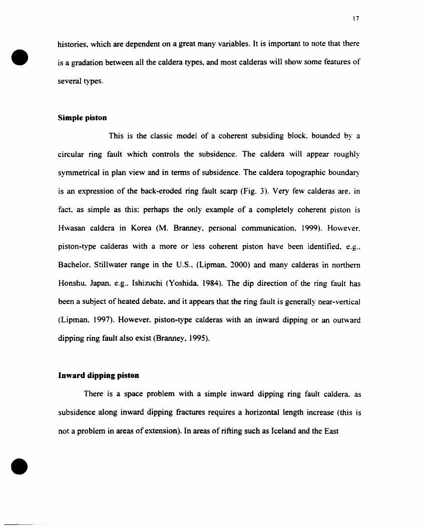
Simple piston
This is the classic model of a coherent subsiding block. bounded by a
circular ring fault which controls the subsidence. The caldera will appear roughly
symmetrical in plan view and in terms of subsidence. The caldera topographie boundary
is an expression of the back-eroded ring fault scarp (Fig. 3). Very few calderas are. in
facto as simple as this: perhaps the only example of a completely coherent piston is
H\vasan caldera in Korea (M. Branney. personal communication. 1999). However.
piston-type calderas with a more or less coherent piston have been identified. e.g..
Bachelor. Stillwater range in the V.S .. (Lipman. 2000) and manY calderas in northern
Honshu. Japan. e.g.. Ishizuchi (Yoshida. 1984). The dip direction of the ring fault has
been a subject of heated debate. and it appears that the ring fault is generally near-vertical
(Lipman. 1997). However. piston-type calderas with an inward dipping or an out\vard
dipping ring fault also exist (Branney, 1995).
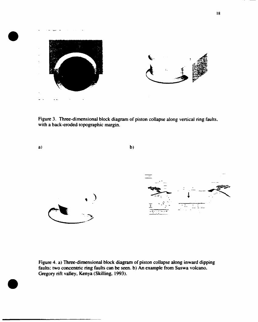
Inward dipping piston
There is a space problem with a simple inward dipping ring fault caldera. as
subsidence along inward dipping fractures requires a horizontal length increase (this is
not a problem in areas ofextension). In areas of rifting such as Iceland and the East
•18
Figure 3. Three-dimensional block diagram of piston collapse along venical ring faults~
with a back·eroded topographie margin.
a)
)
~... ~::..• .-:--,
------_./
b)
.- .~ ... _.
~--~
..... - -"'...:- -~
•Figure 4. a) Three-dimensional block diagram of piston collapse a10ng inward dippingfaults: two concentric ring faults cao he seen. b) An example from Suswa volcaoo~
Gregory rift valley. Kenya (Skilling. 1993).
•
•
19
Africa rift. this caldera type may be common (Gudmundsson. 1998). Piston calderas with
an inward dipping ring fault may be associated with a series of concentric down-stepping
normal tàults outside of the main coherent piston.. producing nested structures with
benches or terraces between ring faults. The Hawaiian calderas may be of this type
(Francis. 1993). At Suswa volcano. Gregory Rift Valley. Kenya. repeated collapses
occurred producing nested. inward dipping pistons (Skilling, 1993) (Fig. 4b).
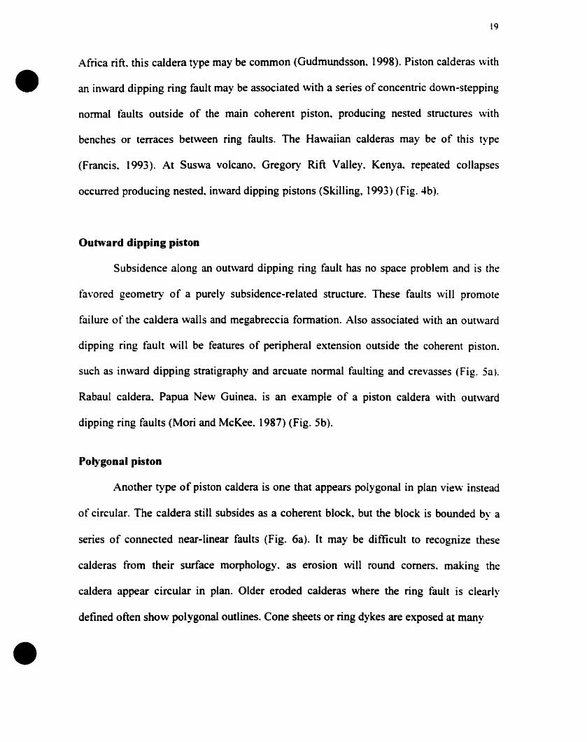
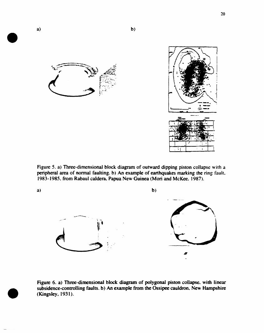
Outward dipping piston
Subsidence along an outward dipping ring fault has no space problem and is the
tàvored geometry of a purely subsidence-related structure. These faults will promote
failure of the caldera walls and megabreccia formation. Also associated with an outward
dipping ring fault will be features of peripheral extension outside the coherent piston.
such as inward dipping stratigraphy and arcuate normal faulting and crevasses (Fig. 5a)_
Rabaul caldera.. Papua New Guinea. is an example of a piston caldera with out\vard
dipping ring faults (Mori and McKee. 1987) (Fig. 5b).
Polygonal piston
Another type of piston caldera is one that appears polygonal in plan vie"- instead
of circular. The caldera still subsides as a coherent block.. but the block is bounded by a
series of connected near-linear faults (Fig. 6a). It may be difficuit to recognize these
calderas from their surface morphology. as erosion \vill round corners. making the
caldera appear circular in plan. Older eroded calderas where the ring fault is clearly
defined often show polygonal outlines. Cone sheets or ring dykes are exposed al many
•a) b)
20
L. ""~--
Figure 5. a) Three-dimensional block diagram of outward dipping piston collapse with aperipheral area of normal faulting. b) An example of earthquakes marking the ring fault.1983-1985. from Rabaul caldera. Papua New Guinea (Mori and McKee. 1987).
a)
_--...........
b)
•Figure 6. a) Three-dimensional block diagram of polygonal piston collapse. with linearsubsidence.controlling faults. b) An example from the Ossipee cauldron. New Hampshire(Kingsley. 1931).
•
•
21
intrusions: although previously described as circular. they actually show a clear
polygonal shape. Excellent examples of this feature are seen in the cauldrons of the
White Mountain Igneous Province. New Hampshire. including the classic structure of
Ossipee cauldron (Fig. 6b).
Ishizuchi cauldron.. Japan.. shows aspects of all four types of piston caldera: it has
two concentric faults in the north dipping inward. while in the south only a single ring
tàult dips outward with evidence for inward tilted stratigraphy (downsagging). The ring
fault even shows a polygonal form (Fig. 7). Nested outward dipping cones also cao he
seen beginning to form.
Downsag calderas
This type of caldera will show inward tilting of pre-caldera stratigraphy that was
originally horizontal (Figs. 2.. 8). There also will he an absence of tangential subsidence
controlling fault scarps (Walker. 1984). This type of caldera will allow ignimbrite sheets
to pond in a depression that is not bounded by significant tangential faults .. implying that
ignimbrite thicknesses will increase gradually towards the center of the depression. rather
than abrupdy across syn-subsidence faults. Previously-erupted ignimbrite sheets will be
back-tilted by the subsidence. Examples of this type of caldera are Rotorua and Taupo.
New Zealand (Walker, 1984) (Fig. Sb). It should be pointed out that downsag calderas
May exhibit faults .. but they are not concentric to the depression and are usually tectonic
in origin. without large displacements across them. It May be rare to find purely
downsagged calderas. as MOst calderas have an element of arcuate concentric faulting.
22
•
3b
----...-<'•
...,I.;:?1
.~
.~.....••...-.
.~..,., .,
Figure 7. Temporal evolution of Ishizuchi cauldron. Japan (Yoshida. 1984). Thisstructure shows a combination of different styles of piston collapse. including subsidencea10ng both inward and outward dipping faults and a polygonal-shaped subsiding block.
a)
small vQlume/deep pluton?.! T'"--- ~!" i ' ..
'.
'~""""""'".. ..... ..- ~ .~.
. .. . ." ."'
b)
c)
•Figure 8. a) A mode1 of a caldera formed by downsagging (Lipman. 1997). withexamples from b) Taupo caldera. New Zealand, and c) Rotorua caldera. New Zealand(walker, 1984).
•
•
.., .._.J
However~ do\vnsagging is an important element of many caldera types. as a high
percentage of calderas show inward tilting of stratigraphy. particularly associated with
areas that are peripheral to the subsidence-controlling faults (Branney. 1995).
Trapdoor calderas
This type of caldera is produced when subsidence is highly asymmetric. A
subsidence-controlling fault with large displacement should exist only on one side of the
caldera (Fig. 2~ 9). The subsidence on the other side of the caldera is controlled largely by
downsagging (Walker. 1984). The downsagged side of the caldera acts as a flexural hinge
and may be associated with small-scale arcuate normal faults. graben and crevasse
formation. Such asymmetric subsidence causes significant variations in the thickness of
the ignimbrite sheet inside the caldera margins. Although it is not a defining
characteristic. these calderas also often show asymmetry in plan vie\v. Examples include
Sïlvenon. Organ Mountains. Eagle Mountain. Big John. Whitehorse and Tuscan
Mountain calderas in the U.S.. Boisena in Central ltaIy. Sakugi in southwest Japan
(Lipman. 1999) and Kumano caldera. southwest Honshu. Japan (Miura. 1999).
Concentric step-dowD calderas
These calderas consist of a series of concentric rings and arcuate faults. Collapse
occurs along these faults. each with small displacement. These faults generally have
increasing displacements towards the center~ although subsidence is not necessarily
symmetric. A small central piston may exist. but its area will be less than haif of the
caldera area (Fig. 10a). The caldera may grow incrementally ourn·ard during subsidence.
s•a)
ft·.......asymmetrical pluton?-1 '. t· :.1.'
• t .: ~ •••
b)
24
1 ~... 1 ......,.__.....'tû 1...:ar.Je-...
.....pc1'M.'!:l;r......ca.a~ I ,....~_t-_
~ .0_ ('~-.mllllllllNr. ,
Figure 9. a) A model of a trapdoor-style caJdera (Lipman, 1997). b) An example fromKumano caldera. southwest Honshu. Japan (Miura.. 1999).
a) b)
•Figure 10. a) Three-dimensional block diagram of step-down concentn(.. collapse.showing a small central piston and concentric nested faults. b) An example fromGuayabo caldera.. Costa Rica (Hallinan.. 1993).
•
•
15
increasing its overall area (Hallinan. 1993). This type of caldera aIso will be associated
with a V-shaped (funnel-shaped) gravity anomaly. Guayabo caldera. Costa Rica. is a
classic example of this type of caldera. showing aIl of the above-mentioned features
(Hallinan. 1993) (Fig. lOb). A concentric pattern of faults exists at Dorobu caldera.
northeastem Honshu, Japan; this was interpreted as representing a series of collapses
moving sequentially toward the caldera center. the opposite case to Guayabo caldera
(Miura and Tamai. (997). Drilling at Valles caldera. New Mexico. originally interpreted
as the classic piston example. has revealed that the caldera has sorne characteristics of
these step-down calderas (Nielson and Hulen. (984). Latera caldera. [taly. also has been
interpreted as this type of caldera. with its formation linked to multiple collapse episodes
(Barberi et aL. (984).
Chaotic calderas
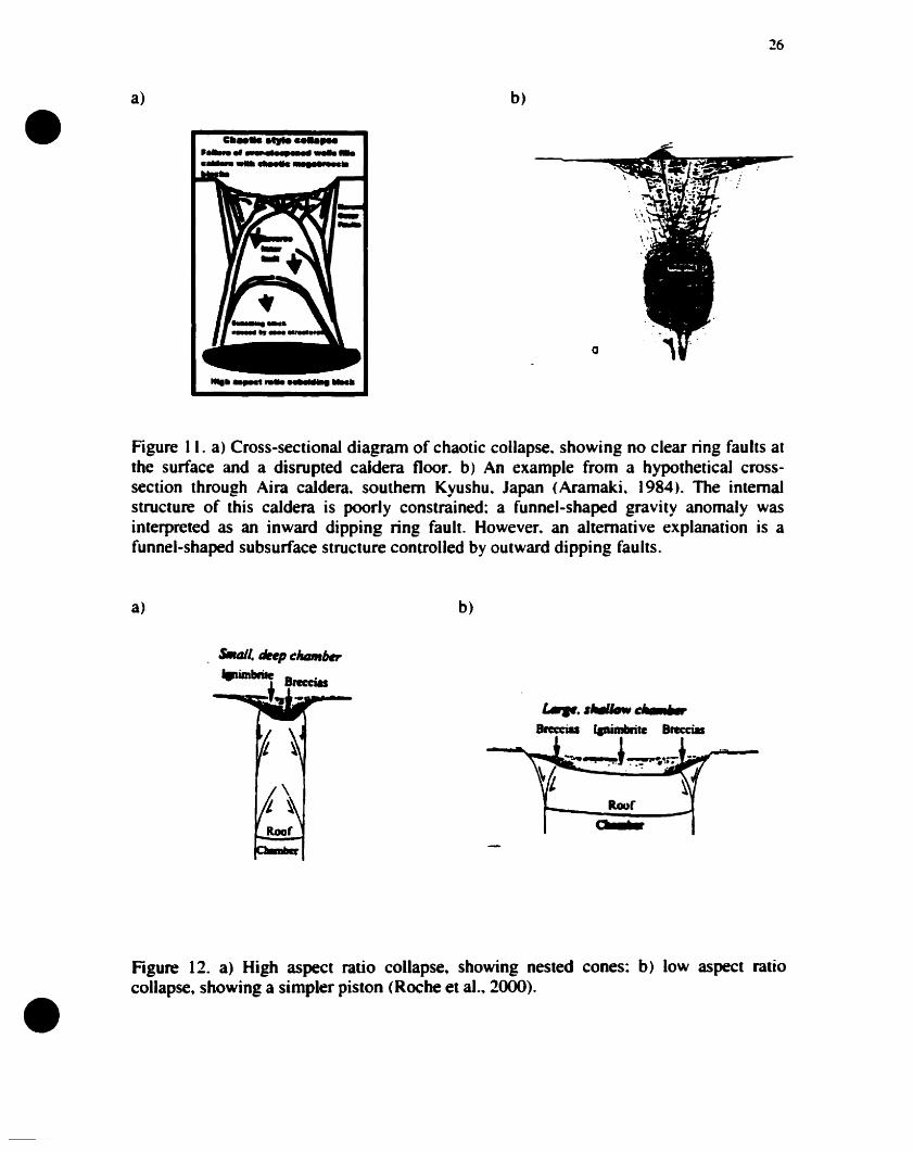
These calderas tend to be of smaller scale « 15 km diameter) than many of the
other types. The caldera floor is disrupted. without clear subsidence-controlling faults
(Fig. lia). Faults located lower within the subsiding block may produce multiple nested
cones (Roche et al.. 2000) (Fig. 12). The topographie wall of the caldera represents the
slide surfaces of foundering blocks. not a ring fault. This type of collapse is often
associated with the collapse of a volcanic edifice that previously has been hydrothermally
weakened. Slide blocks and faults blocks will become rnixed and fonn the caldera floor.
This low-density brecciated rnaterial that forms the caldera floor produces a V-shaped
gravity low. These calderas have been termed funnel calderas in sorne reviews; this leads
•a)
c ...., ..................- ....
b)
a
26
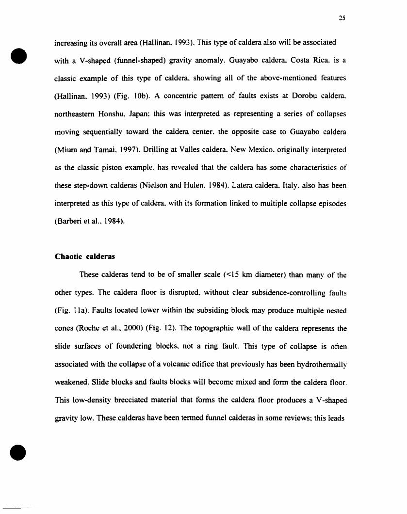
Figure Il. a) Cross-sectionaJ diagram of chaotic collapse. showing no clear ring faults althe surface and a disrupted caldera floor. b) An example from a hypothetical crosssection through Aira caldera. southem Kyushu. Japan (Aramaki. 1984). The internaistructure of this caldera is poorly constrained: a funnel-shaped gravity anomaly wasinterpreted as an inward dipping ring fault. However. an alternative explanation is afunnel-shaped subsurface structure controlled by outward dipping faults.
a) b)
0;
".".. IlwlIow c&•••6.Brecc1a lpimbritc Breccias
~ _.'!,.~,J~~~-~ ~
Roor
Roor
. s.tJ/1. liftp chtlm,..
IFimbrile Bnccia.....-..op.+••-:t....-
•Figure 12. a) High aspect ratio collapse. showing nested cones: b) low aspect ratiocollapse, showing a simpler piston (Roche et al.• 2(00).
•
•
'27
to confusion~ however~ as caIderas of many types show a funnel-shaped gravity profile
(Lipman~ 2000).
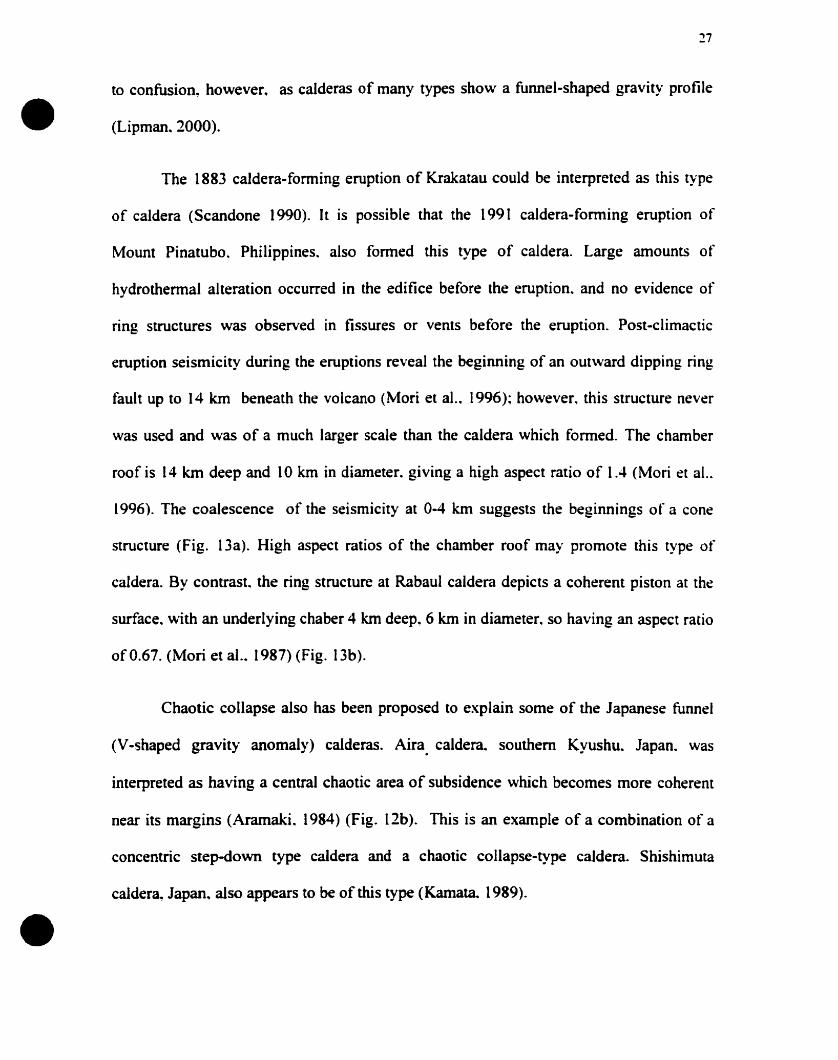
The 1883 caldera-forming eruption of Krakatau could be interpreted as this type
of caldera (Scandone 1990). Il is possible that the 1991 caldera-forming eruption of
Mount Pinatubo. Philippines. aIso formed this type of caldera. Large amounts of
hydrothermal alteration occurred in the edifice before the eruption. and no evidence of
ring structures was observed in fissures or vents before the eruption. Post-climactic
eruption seismicity during the eruptions reveal the beginning of an outward dipping ring
fault up to 14 km beneath the volcano (Mori et al.. 1996); however, this structure never
was used and was of a much larger scale than the caldera which fonned. The chamber
roof is 14 km deep and 10 km in diameter. giving a high aspect ratio of 1.4 (Mori et al..
1996). The coalescence of the seismicity at 0-4 km suggests the beginnings of a cone
structure (Fig. 13a). High aspect ratios of the chamber roof may promote this type of
caldera. By contrast. the ring structure at Rabaul caldera depicts a coherent piston at the
surface. with an underlying chaber 4 km deep. 6 km in diameter. 50 having an aspect ratio
of 0.67. (Mori et al.. 1987) (Fig. 13b).
Chaotic collapse also has been proposed to explain sorne of the Japanese funnel
(V-shaped gravitY anomaly) caIderas. Aira. caldera. southem Kyushu. lapan. was
interpreted as having a central chaotic area of subsidence which becomes more coherent
near its rnargins (Aramaki. 1984) (Fig. 12b). This is an example of a cornbination of a
concentric step-down type caldera and a chaotic collapse-type caldera. Shishimuta
caIdera~ lapan~ also appears to he of this type (Kama~ 1989).
•a)
...: 'I~.~:~:.~~.
1 .: :':t' ••. ..-.,..:. .1 .'.~ ~-...: ~ '. ... -: ..... :-
-.-:
...=----.---..-....;--
b)
I.---~pp ft
.--==
28
Figure 13. a) High aspect ratio magma chamber al Mount Pinatubo. Philippines. asillustrated by posl-climactic eruption seismicity. 29 June-16 August 1991 (Mori et al..1996), b) Low aspect ratio magma chamber at Rabaul caldera. Papua New Guinea. basedon seismicity between late 1983 and rnid 1985 (Mori and McKee. 1987).
a) b)
,:...
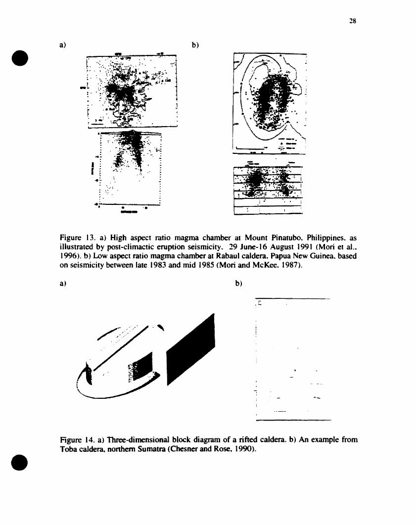
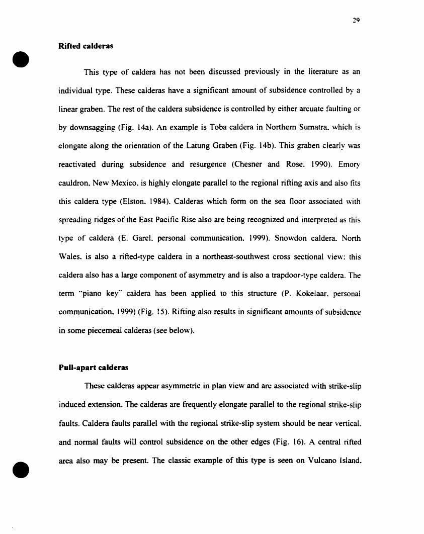
•Figure 14. a) Three-dimensional block diagram of a rifted caldera. b) An example fromToba caJde~ nonhem Sumatra (Chesner and Rose. 1990).
•
•
29
Rifted calderas
This type of caldera has not been discussed previously in the literature as an
individuai type. These calderas have a significant amount of subsidence controlled by a
linear graben. The rest of the caldera subsidence is controlled by either arcuate faulting or
by downsagging (Fig. 14a). An example is Toba caldera in Northem Sumatra. which is
elongate along the orientation of the Latung Graben (Fig. 14b). This graben clearly was
reactivated during subsidence and resurgence (Chesner and Rose. 1990). Emory
cauldron. New Mexico. is highly elongate parallel to the regional rifting axis and also tits
this caldera type (Elston. 1984). Calderas which form on the sea floor associated with
spreading ridges of the East Pacifie Rise also are being recognized and interpreted as this
type of caldera (E. Gare!. personal communication~ 1999). Snowdon caldera. North
Wales. is aiso a rifted-type caldera in a northeast-southwest cross sectional view: this
caldera also has a large cornponent of asymmetry and is also a trapdoor-type caldera. The
term "piano key" caldera has been applied to this structure (P. Kokelaar. personal
communication. 1999) (Fig. 15). Rifting aIso results in significant amounts of subsidence
in sorne piecemeal calderas (see below).
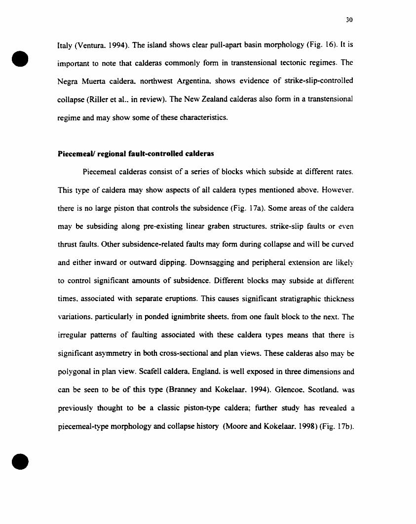
Pull-apart calderas
These calderas appear asymmetric in plan view and are associated with strike-slip
induced extension. The caIderas are frequently elongate paraIlel to the regional strike-slip
faults. Caldera faults parallel with the regional strike-slip system shouid be near vertical.
and normal faults will control subsidence on the other edges (Fig. 16). A central rified
area aIso may he present. The classic example of this type is seen on Vulcano Island.
•
•
30
Italy (Ventura. 1994). The island shows clear pull-apart basin morphology (Fig. 16). ft is
important to note that calderas commonly form in transtensional tectonic regimes. The
Negra Muerta caldera. northwest Argentina.. shows evidence of strike-slip-controlled
collapse (Riller et al. .. in review). The New Zealand calderas also form in a transtensionaI
regime and May show sorne of these characteristics.
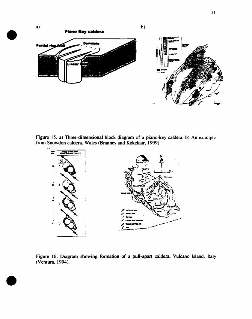
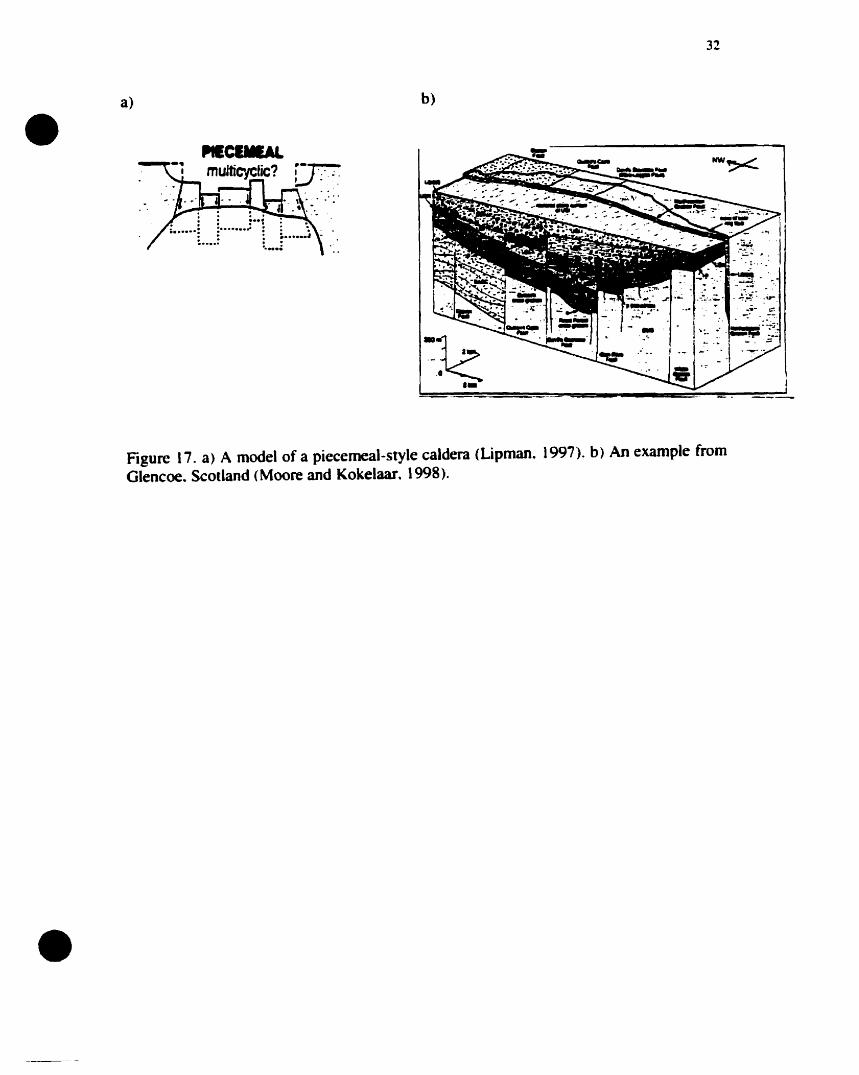
Piecemeall regional fault-controlled calderas
Piecemeal calderas consist of a series of blocks which subside at different rates.
This type of caldera May show aspects of ail caldera types mentioned above. However.
there is no large piston that controls the subsidence (Fig. 17a). Sorne areas of the caldera
May be subsiding along pre-existing linear graben structures. strike-slip faults or even
thrust faults. Other subsidence-related faults may fonn during collapse and will be curved
and either inward or outward dipping. Downsagging and peripheral extension are likely
to control significant amounts of subsidence. Different blocks may subside at different
times. associated with separate eruptions. This causes significant stratigraphie thiekness
variations. partieularly in ponded ignimbrite sheets. from one fault block to the next. The
irregular patterns of faulting associated with these caldera types means that there is
significant asymmetry in both cross-sectional and plan views. These calderas aIso May be
polygonal in plan view. Scafell caldera.. England. is weil exposed in three dimensions and
can be seen to be of this type (Branney and Kokelaar. (994). Glencoe. ScotIand. \Vas
previously thought to be a c1assic piston-type caldera; further study has revealed a
piecemeal-type morphology and collapse history (Moore and Kokelaar. 1998) (Fig. 17b).
•a) h)
.---"
31
Figure 15. a) Three-dimensional block diagram of a piano-key caldera. b) An examplefrom Snowdon caldera.. Wales (Branney and Kokelaar. 1999).
,..... ---------!
i1••
•Figure 16. Diagram showing fonnation of a pull-apan caldera.. Vulcano Island.. Italy(Ventura.. 1994).
•a)
32
b)
•
Figure 17. a) A model of a piecemeal-style caldera (Lipman. 1997). b) An example fromGlencoe. Scotland (Moore and Kokelaar. 1998).

33
Stages in the Temporal Evolution of Calderas
•This section will attempt to illustrate sorne of the different stages that are olten
involved in formation of a caldera. Little is known about the early stages in caldera
formation. and they are often neglected in the literature; because the base of the subsiding
block is rarely well-preserved. A largely conceptual approach to the temporal
development of calderas therefore has been adopted. At each stage there are a number of
different scenarios that will interact to eventually forro a caldera. This section aims to
illustrate sorne of the processes that are responsible for the formation of the different
caldera types. While this approach is similar in sorne respects to that of Smith and Bailey
(1968). it is fundamentally different in other respects by attempting to view caldera
development as a series of structural events which are related in a spatial and temporal
sense.
Stage 1. Magma chamber intrusion
Large. shallow (2-10 km). sill-like magma chambers are associated with calderas
(Gudmundsson. 1988. 1997. 1998; Lipman. 1997. 2000). For the intrusion of such
magma chambers. cenain tectonic conditions are needed. Some degree of upper crustal
extension is required to create the space necessary for the intrusion. If this upper crustal
extension is not sufficient. doming of the surface may result. This doming may he the
result of (1) faults formed by forceful intrusion: (2) upper crustal volume changes caused
by thermal expansion; (3) elastic plate bending caused by magma pressure (Withjack and
Scheiner, 1982); and (4) faulting and structural uplift caused by overpressure. The latter
• is local and of low magnitude, producing small structures which may not he significant to
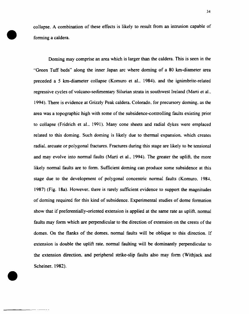
•
•
34
collapse. A combination of these effects is likely to result from an intrusion capable of
forming a caldera.
Doming may comprise an area which is larger than the caldera. This is seen in the
'''Green Tuff beds" along the inner Japan arc where doming of a 80 km-diameter area
preceded a 5 km-diameter collapse (Komuro et al.. 1984). and the ignimbrite-related
regressive cycles of volcano-sedimentary Silurian strata in southwest Ireland (Marti et al..
1994). There is evidence at Grizzly Peak caldera. Colorado.. for precursory doming. as the
area was a topographie high with sorne of the subsidence-controlling faults existing prior
to collapse (Fridrich et al.. 1991). Many cone sheets and radial dykes were emplaced
related to this doming. Such doming is Iikely due to thermal expansion. which creates
radial. arcuate or polygonal fractures. Fractures during this stage are likely to he tensional
and may evolve into normal faults (Marti et al.. 1994). The greater the uplift. the more
likely normal faults are to fonn. Sufficient dorning cao produce sorne subsidence at this
stage due to the development of polygonal concentric normal faults (Komuro.. 198..t
1987) (Fig. 18a). However. there is rarely sufficient evidence to suppon the magnitudes
of doming required for this kind of subsidence. Experimental studies of dome formation
show that if preferentially-oriented extension is applied at the same rate as uplift. nonnal
faults may form which are perpendicular to the direction of extension on the crests of the
domes. On the flanks of the domes.. normal faults will be oblique to this direction. If
extension is double the uplift rate. nonnal faulting will be dominantly perpendicular to
the extension direction.. and peripheral strike-slip faults also may fonn (Withjack and
Scheiner.. 1982).
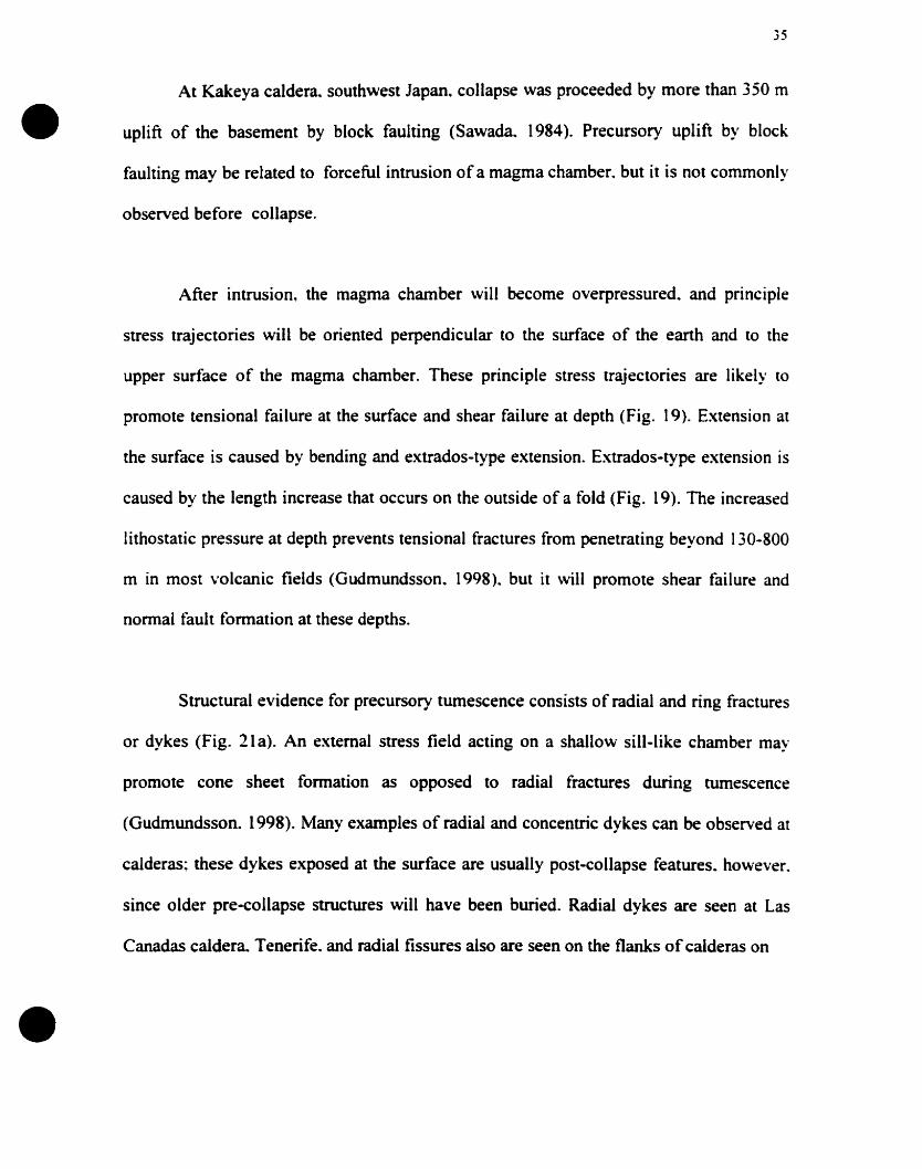
•
•
35
At Kakeya caldera~ southwest Japan. collapse was proceeded by more than 350 m
uplift of the basement by black faulting (Sawada. 1984). Precursory uplift by block
faulting may be related to forceful intrusion of a magma chamber. but it is not commonly
observed before collapse.
After intrusion. the magma chamber will become overpressured. and principle
stress trajectories will be oriented perpendicular to the surface of the earth and to the
upper surface of the magma chamber. These principle stress trajectories are likely (0
promote tensional failure at the surface and shear failure at depth (Fig. 19). Extension al
the surface is caused by bending and extrados-type extension. Extrados-type extension is
caused by the length increase that occurs on the outside of a fold (Fig. 19). The increased
lithostatic pressure at depth prevents tensional fractures from penetrating beyond 130-800
m in most volcanic fields (Gudmundsson. 1998). but it will promote shear failure and
normal fault formation al these depths.
Structural evidence for precursory tumescence consists of radial and ring fractures
or dykes (Fig. 21 a). An external stress field acting on a shallo\\l sill-like chamber may
promote cone sheet formation as opposed to radial fractures during tumescence
(Gudmundsson. 1998). Many examples of radial and concentric dykes can be observed al
calderas: these dykes exposed at the surface are usually post-collapse features. however.
since older pre-collapse structures will have been buried. Radial dykes are seen at Las
Canadas caIdera. Tenerife. and radial fissures aIso are seen on the flanks of caIderas on
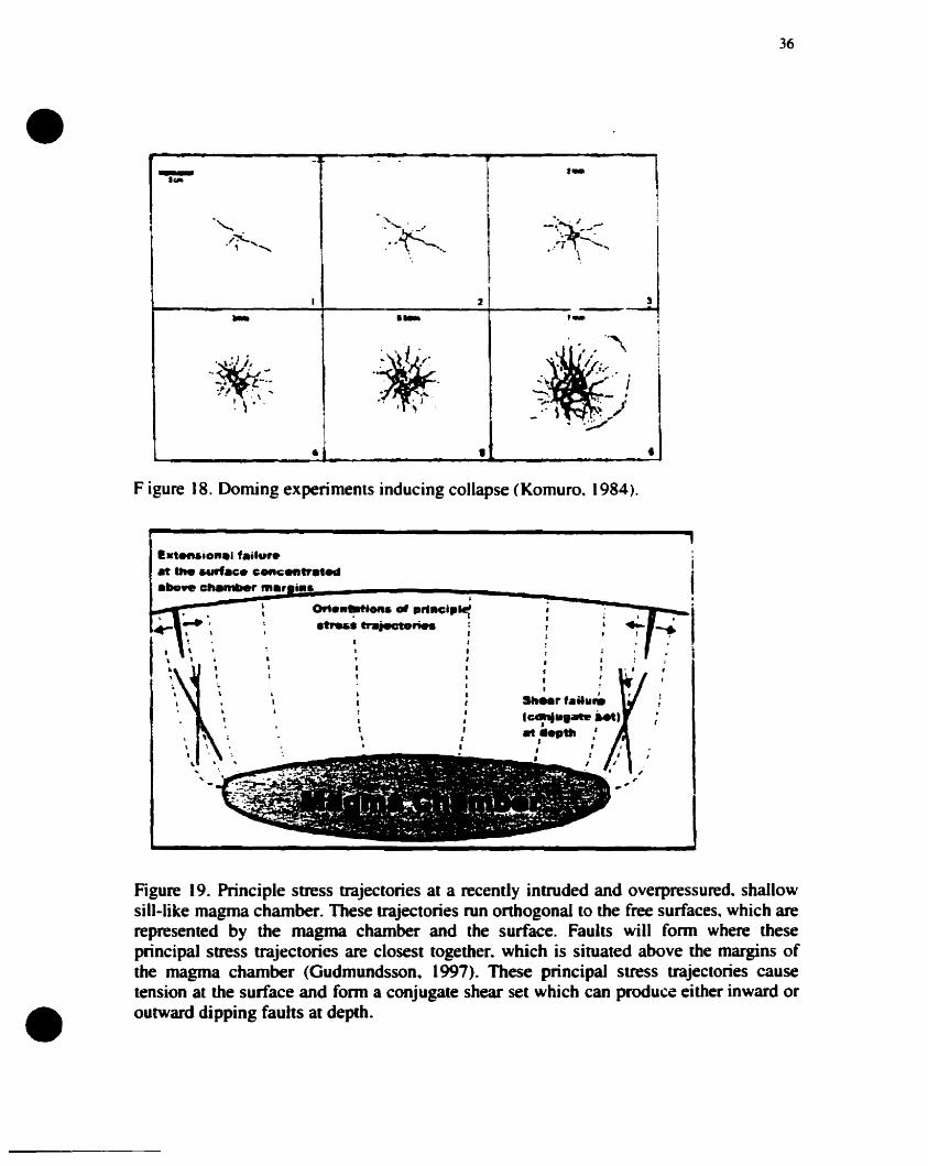
•36
.- t_.~
. -
~~ -:'~ - 1........ .\ ,-'.
1
,.'..... . -. , "" • 1 .... ...'T \ " ..
1 2 ._-j.. la- I,'\ ,i
.~ "i >. i
~.. ,'. !
_.. t_ • ...1."" ..
j,., .. ~.: ~.:~ . ,.' ;
, . , \ ......... - ,1 ., . . )
_:-: \ .~ ..~l' 1 .,' .
. .';:./
• , •Figure 18. Doming experiments inducing collapse (Komuro. 1984),
ie.tenaionel f.ïlur.,. the ..,rfa~. conc;entrllted.bowe clUlmiler "'., i••
1
111
S"••r tail.".~u......1M,."'. .', ,
• f1
1,1
1,1
11
1l
••1
1
•
1
1!
1t\
•
Figure 19. Principle stress ttajectories at a recently intruded and overpressured. shallowsill-like magma chamber. These trajectories run onhogonal to the free surfaces. which arerepresented by the magma chamber and the surface. Faults will fonn where theseprincipal stress trajectories are closest together. which is situated above the margins ofthe magma chamber (Gudmundsson. 1997). These principal stress trajectories causetension al the surface and fonn a conjugate shear set which cao produce either inward oroutward dipping faults al depth.
•
•
37
Femandina and Isabella caJderas. Galapagos Islands (Chadwick and Dieterich. 1995)
(Fig. 20a). Cone sheets are beautifully preserved in Gran Canaria. Canary Islands
(Schimick et al.. 1999) (Fig. 20b) and Volcan A1cedo. Galapagos Islands (Fig. 20c).
Cone sheets also are common at eroded igneous ring complexes as seen in many of the
Tertiary Northwest Scottish intrusions. The radial fissures and the cone sheets and lor
vertical ring dykes seen on the Galapagos volcanoes may be due to magma pressure from
a flat-topped magma chamber which is not necessarily the result of precursory
tumescence but instead a general feature of magma pressure (Anderson. 1936: Chadwick
and Dieterich. 1995).
Very rapid extension may result in classic graben formation (Fig. 21 c) with less
doming. Evidence for this is illustrated by the rifts seen at Toba and Snowdon (P.
Kokelaar. personal communication. 1999: C. Chesner. personal communication. 2000)
(Figs. 14. 15). In the case of a strong transtensional system which is often associated with
caldera-forming environments. the beginnings of pull-apart basin structures may form
oblique to strike-slip systems. Vulcano Island. Italy. illustrates this tectonic reglme
(Ventura. 1994) (Fig. 16).
Structural evidence for precursory doming is aften absent at calderas (Lipman.
1997): this implies that a passive intrusion may be common. or that precursory
tumescence evidence is 10st due to later deformation episodes. Passive intrusion of the
pluton will result in only limited thermal doming, without substantial fracturing of the
surface; stratigraphy may dip away from the center of the intrusion. The only evidence
for this would be in the uplift and erosional history of the area. From the sedimentary
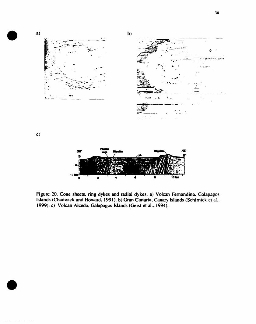
. '--- ....
38
------ --; ::r~"'-: r :,- ::~-'!:
- ......
1.' ~:: • _.
.... ...
b)
.-- ...._ ......-. --.-.- --..-.- --~ ,.,
..1 •
a)•
c)
-1o •
.......,
Figure 20. Cone sheets. ring dykes and radial dykes. a) Volcan Femandina. GalapagosIslands (Chadwick and Howard. (991). b) Gran Canaria. Canary Islands (Schimick el al..1999). c) Volcan Alcedo. Galapagos Islands (Geist et al.. 1994).
•
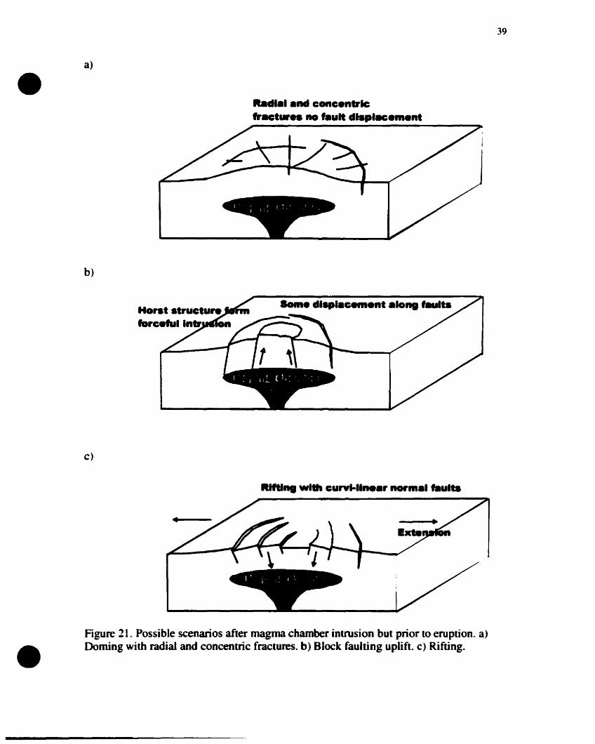
•a)
bd••1.nd coneentrlc"'lICt.... no f8ult dl.pIHem.nt
b)
39
c)
Horst struetu...foreefu. Intr_1on
SoIne dl.l.e.....nt .Iong f8ults
•Figure 21. Possible scenarios after magma chamber intrusion but prior to eruption. a)Doming with radial and concentric fractures. b) Block faulting uplift. c) Rifting.
•
•
~o
record unconformities could reveal details of uplift and erosion; sedimentation rates also
can be used to determine uplift and erosion rates.
Stage 2. Initial erup.ion and chamber evacua'ion.
Maximum overpressure is reached within the chamber before the initial eruption.
1f fractures produced during intrusion penetrate from the surface down to the magma
chamber. they will be used for the initial eruption. If overpressures exceed the tensile
strength of the rock. new fractures can be created which will propagate up from the edges
of the magma chamber. These initial fractures will form as a result of the orientation and
concentration of the principal stresses (Fig. 19). Overpressures within the chamber are
likely to exploit preferentially·oriented weaknesses or fractures in the crust. forming a
conduit that runs from the magma chamber to the surface (Fig. 22). Initial eruptions from
Ishizuchi cauIdron. Japan. occurred along fissures parallel to the principal regional
compressional stress (Yoshida. 1984) (Fig. 7). At Crater Lake. Cascades. U.S.A. there is
evidence for a single vent phase before a ring vent eruption phase (Bacon. 1983).
The initial eruption is likely to continue only so long as conduits are kept open by
magma pressure. Once pressure is reduced to lithostatic at the top of the chamber.
conduits will close and eruptions will stop (McLeod.. 1999). Therefore. only limited
eruption volumes appear to be possible at this overpressured stage (Druin and Sparks.
1984; Gudmundsson, (998). Several calderas show evidence for an initial small-volume
plinian eruplion before large-volume pyroclastic tlow eruptions occur. The caldera
fonning events at Valles caldera sho\v the plinian fallout unit from the Lower Bandelier
Tuffhas a volume ofonIy 20 km3 (Dense Rock Equivalent.. ORE) compared to 400 km3
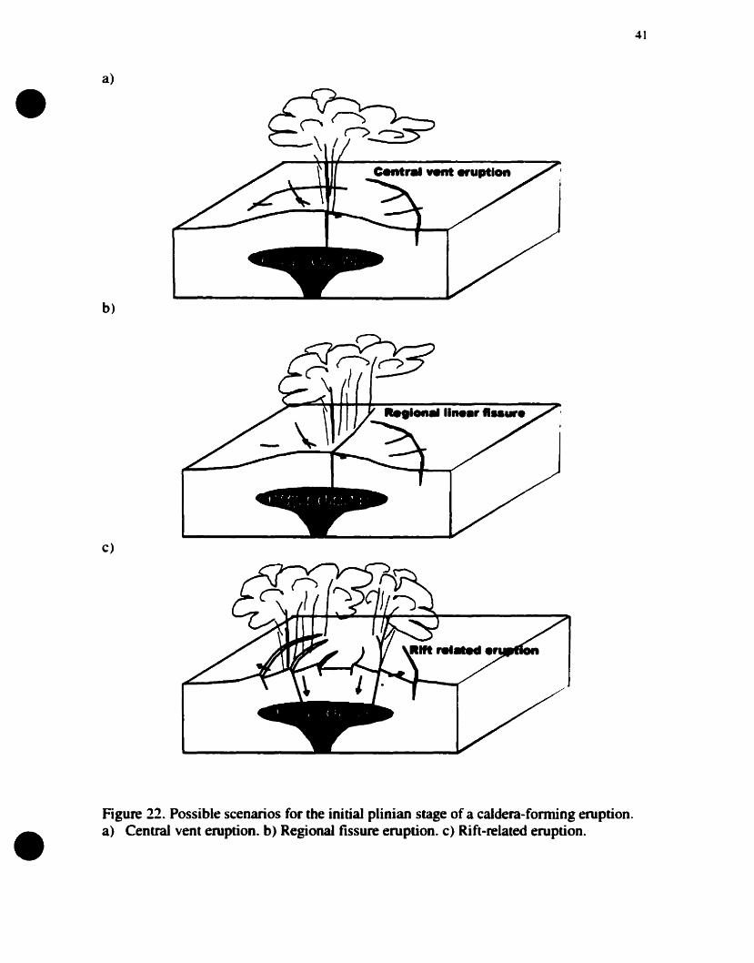
•a)
b)
c)
41
Figure 22. Possible scenarios for the initial plinian stage of a caldera-fonning eruption.a) Central vent eruption. b) Regional fissure eruption. c) Rift-related eruption.
42
DRE of pyroclastic flows. The upper Bandelier Tuff consists of 15 km3 DRE of plinian
• fall and 250 km} DRE of pyroclastic flows (Selfand Lipman. 1989).
This initial plinian stage may not occur if magma viscosities are low. as in the
case of most basaltic calderas. or if vent geometries are not appropriate. If the magma in
the charnber is allowed to degas. then high overpressures may never develop. and this
initial plinian stage may not occur. An initial plinian phase was not seen at the relatively
small caldera-forming event at Mount Pinatubo. Philippines. in 1991 (Gerlach and
Westrich. 1992).
Stage 3. Downsagging and the onset of subsidence
Unless there \Vas substantial extension during the early stages. tàults will not have
developed sufficiently for instantaneous failure. A period of bending and sagging of the
caldera roof will help propagate tensional fractures downward and shear fractures upward
(Fig. 23). This early stage of surface downsagging is clearly seen in experimental models
(Marti et al.. 1994: Roche et al ... 2000: this thesis). An initiai period of downsagging
dominated subsidence was seen before ring faults became active al Grizzly Peak caldera.
Colorado (Fridrich et aL.. 1991). Many calderas show inward-tilted beds.. especially al
early stages. which are a direct result of downsagging (Walker. 1984). If these fracture
sets never fully develop. a downsag-style caIdera develops. Taupo caIdera.. New ZeaJand.
has been interpreted as such a downsag caldera (Walker, 1984) (Fig. 8b). ScaIed models
show that a ring fault will develop on one side frrst.. producing initiaIly asymmetric
subsidence: sorne magma chamber roof aspect ratios will promote this more than others
•
•
•
(Burov and Guillou-Frottier~ 1999~ Roche et aL 2000~ this thesis). This initial
asymmetric subsidence will be exaggerated by any heterogeneities in magma chamber
geometry or crustal strength. If the initial conduit is near to vertical and located close to
the chamber margins~ it also rnay be used for subsidence at this stage. This is seen al
Ishizuchi cauldron~ Japan~ where sections of the initial eruptive fissures were interpreted
to control the initial period of subsidence (Yoshida.. (984) (Fig. 7).
This bending period also will result in the rotation of tensional fractures or normal
faults formed by tumescence. The sags at the surface and at the chamber roof also will
change the orientation of the principal stress trajectories (Fig. 23). Rotation will cause
inward dipping fracture to be rotated towards the vertical. which is a more favourable
orientation for subsidence (Fig. 23). Depending on the amount of rotation caused by
sagging and the original orientation of the fractures. sorne features produced by
tumescence could be re-used during the various stages of subsidence.
The orientation of the initial fault. which controls subsidence. will depend on the
presence or absence of a superimposed stress regime. In the absence of a superirnposed
stress regime, the fault is likely to be outward dipping (Roche et al.. 2000). This fault will
allow funher eruption.. since the geometry ofthis fault favors large volumes to be erupted
at this stage. For example.. the motion of the subsiding black will keep this fault or
conduit open even when the pressure in the magma chamber drops below lithostatic (Fig.
24).
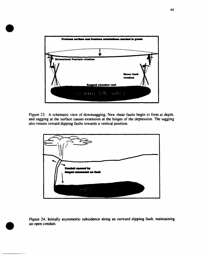
•
•
44
.'wl•• _ ~fr __~ ..-
...................+ ............................... . .~. "".." -
Figure 23. A schematic view of downsagging. New shear fauhs begin to farm at depth.and sagging at the surface causes extension at the hinges of the depression. The saggingalso rotates inward dipping faults towards a venical position.
.....C.n~1IIt ., ...... _t.....-·__......
Figure 24. Initially asymmetric subsidence a10ng an autward dipping fault. maintainingan open conduit.
•~5
If ring faults were partially formed by earlier stages of extension and intrusion.
fault-controlled subsidence is possible at this early stage (Fig. 25). [n this case.
subsidence will be extension-controlled rather than eruption-controlled due to the space
problem created by inward dipping fractures. This results in an inward dipping piston
type caldera. e.g.. Kilauea caldera. Hawaii. [f weIl developed regional faults suitable for
subsidence exist. they also can he used at this stage without the need for sagging. Use of
such faults can be seen in the early stages in the development of Glencoe caldera.
Scotland. which is a tectonically-controlled piecemeal caldera (Moore and Kokelaar.
1998).
Stage 4. Main subsidence and eruption phase.
The initial subsidence-controlling fault and the nature of the movement upon this
structure is likely ta significantly alter the stress field associated with the chamber.
Movement on this fault will increase the bending on the opposite side of the caldera.
promoting tensional failures and normal faulting (Fig. 26). Experimental studies support
this idea (Odonne et al.. 1999: Roche et aL. 2000: this thesis) (Fig. 26). [nitial subsidence
upon an inward dipping fault. without sufficient extension. may resuIt in a outward
dipping fault forming on the opposite side. as seen al lsruzuchi cauldron. lapan (yoshida.
1984).
As subsidence continues. the initial fault will propagate laterally from the sid~ of
maximum subsidence (Roche et al.. 2000: this thesis). This fauIt may never propagate
fully to the other side, resulting in a trapdoor-style caldera (Fig.9). e.g., Silvenon. Organ
Mountains, Eagle Mountain. Big John, Whitehorse and Tuscan mountain calderas in the
• U.S., Bolsena in Central Italy and Sakugi in southwestem Japan (Lipman, 2000). [n the
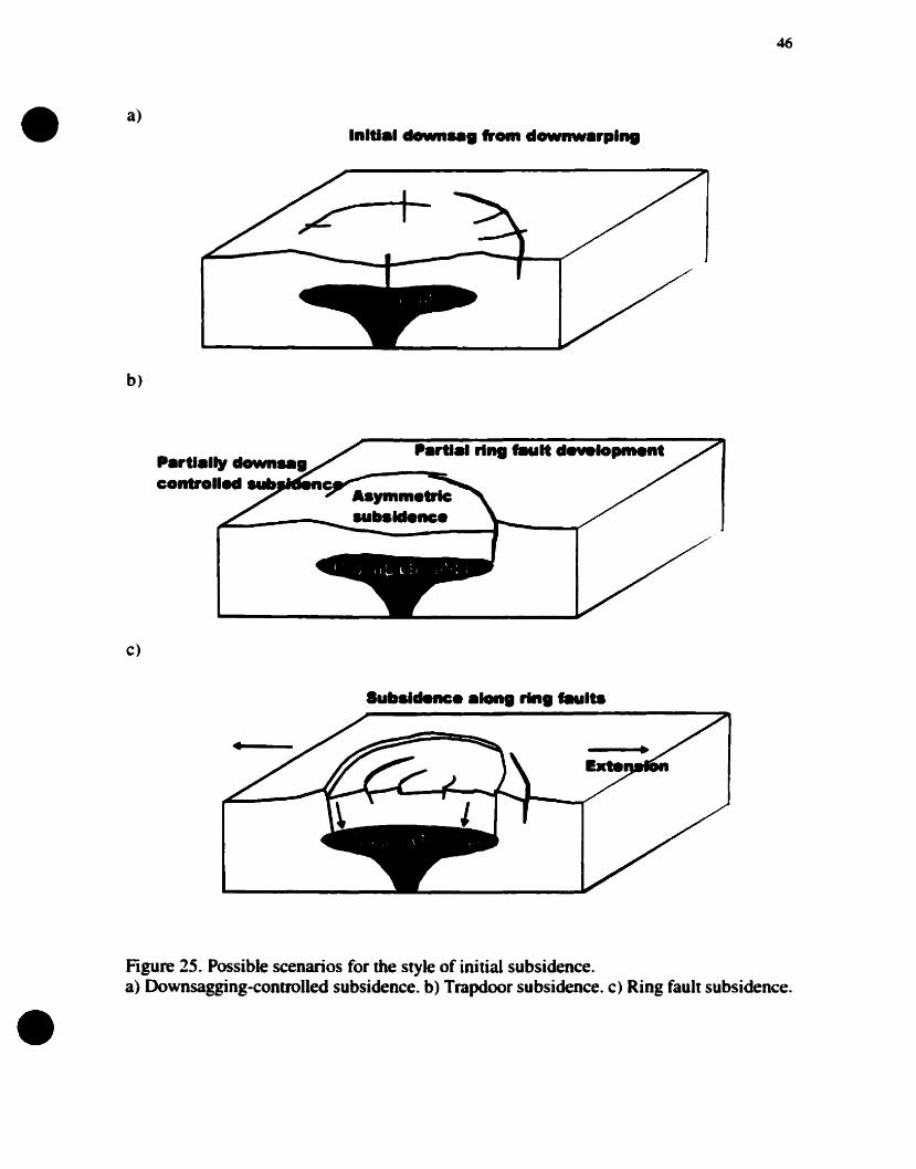
•46
a)
b)
c)
P.rtl.,1y clown...contro••_ ."_Ien
P.rtl., ri... lIIult development
Subsidence ..... rln........
•Figure 25. Possible scenarios for the style of initial subsidence.a) Downsagging-eontrolled subsidence. b) Trapdoor subsidence. c) Ring fault subsidence.
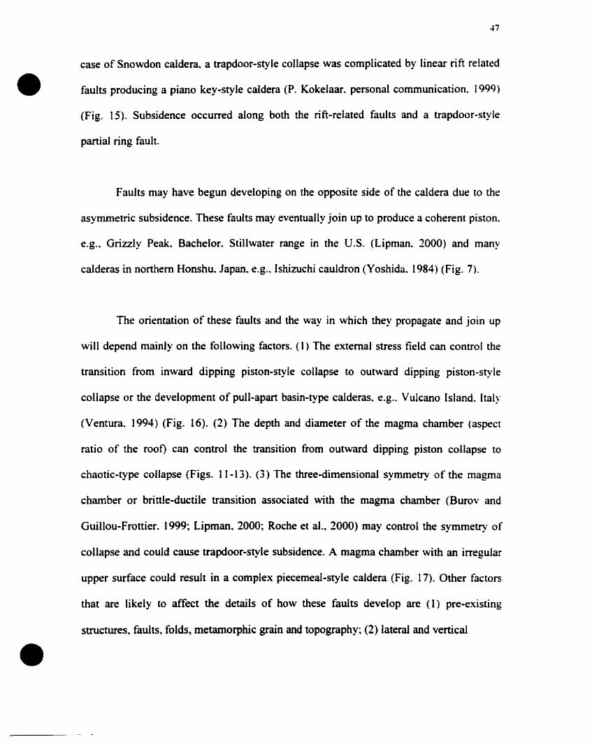
47
case of Snowdon caldera~ a trapdoor-style collapse was complicated by linear rift related
• faults producing a piano key-style caldera (P. Kokelaar. personal communication. 1999)
(Fig. 15). Subsidence occurred along both the rift-related faults and a trapdoor-style
partial ring fault.
Faults May have begun developing on the opposite side of the caldera due to the
asymmetric subsidence. These faults May eventually join up to produce a coherent piston.
e.g., Grizzly Peak. Bachelor. Stillwater range in the V.S. (Lipman. 2000) and Many
calderas in northem Honshu. Japan. e.g.. Ishizuchi cauldron (Yoshida. 1984) (Fig. 7).
The orientation of these faults and the way in which they propagate and joïn up
will depend mainly on the following factors. (1) The extemal stress field can control the
transition from inward dipping piston-style collapse to outward dipping piston-style
collapse or the development of pull-apart basin-type calderas. e.g.. Vu1cano Island. Italy
(Ventura. 1994) (Fig. 16). (2) The depth and diameter of the magma chamber (aspect
ratio of the root) can control the transition from outward dipping piston collapse to
chaotic-type collapse (Figs. 11-13). (3) The three-dimensional symmetry of the magma
chamber or brittle-ductile transition associated with the magma chamber (Burov and
Guillou-Frottier. 1999; Lipman. 2000; Roche et al., 2000) may control the symmetry of
collapse and could cause trapdoor-style subsidence. A magma chamber with an irregular
upper surface could result in a complex piecemeal-style caldera (Fig. 17). Other factors
that are likely to affect the details of how these faults develop are (1) pre-existing
structures~ faults, falds, metamorphic grain and topography; (2) lateraI and venical
•
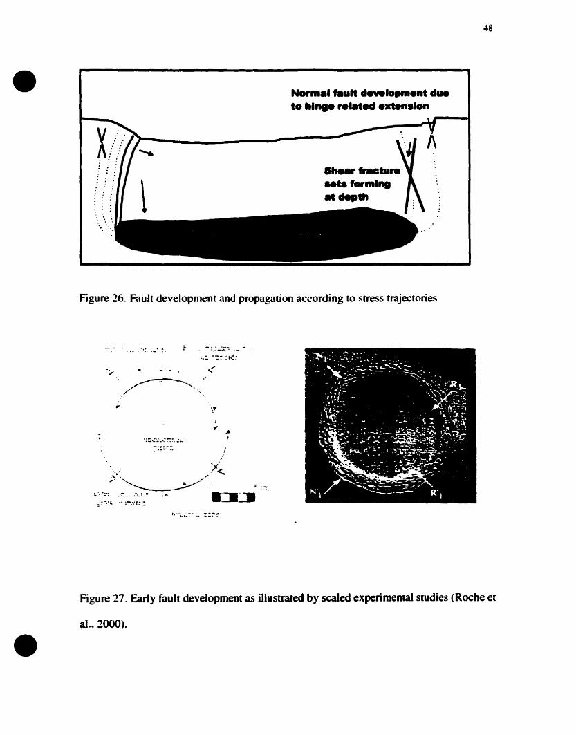
48
• Nor••1"ult ....Io......nt dueto h..... r.lM••xtenslon
.....rhctu...Mtalorml...........
f\
Figure 26. Fault development and propagation according to stress trajectories
.... r ...... - ....- .'
If'
-..... ---.. ,. .. /1
1
)/".' .' <..~. ,
, ......,. ./" . : -~, _:1".
~'. ';::.•'::- :lL~ -=:'.:.:11_. ... .' .;-:.-n::
1
fi ..,
..
Figure 27. Early fault development as illustrated by scaled experimental srudies (Roche et
al .• 2000).
•
•
variations in the tensile strength of the rocks that comprise the subsiding block. e.g..
hydrothermaIly-weakened areas which are common in volcanic terrains; (3) the position
of the erupted ignimbrite sheets within the caldera. which add load to the subsiding black.
These factors will promote deviation from the classic model.. and interactions of many of
these factors will result in a complex mix of caIdera types. Caldera faults may develop as
a series of linear faults which connect to form distinct corners. as in the polygonal style
(Fig. 6), rather than a continuous ring as in the piston styles (Figs. 3-5).
Stage S. Eruption quiesf:ence and peripberal extension.
As the main subsidence-controlling faults develop. outer faults also grow which
are related to extension caused by the subsidence (Walker. 1984: Branney. 1995: Roche
et al.. 2000: this thesis). These faults are thus a response to the main caldera faults located
in more central regions of the caldera. The faults may form along tensional fractures that
were created during bending from either tumescence or downsagging. The steep tàult
scarps produced by the main subsidence phase will be subject to failure. These fault
scarps will be funher steepened by peripheral downsagging and extension. Large
megabreccia blocks may slide into the caldera at this stage (Lipman. (997). The same
forces that are responsible for these slide blocks aJso will produce peripheral normal
fauIting in the region outside the main subsidence area (Fig. 28). Arcuate crevasses aIso
may form related to slide blacks (Branney.. (995). Peripheral graben and normal faulting
may form in areas where no clear subsidence-controlling fault has formed. and bending is
at a maximum (Fig. 29). These structures are weil eXPQsed al Scafell caldera. England.
and Snowdon calder~ Wales (Branney, 1995: Kokelaar and Branney. (999).
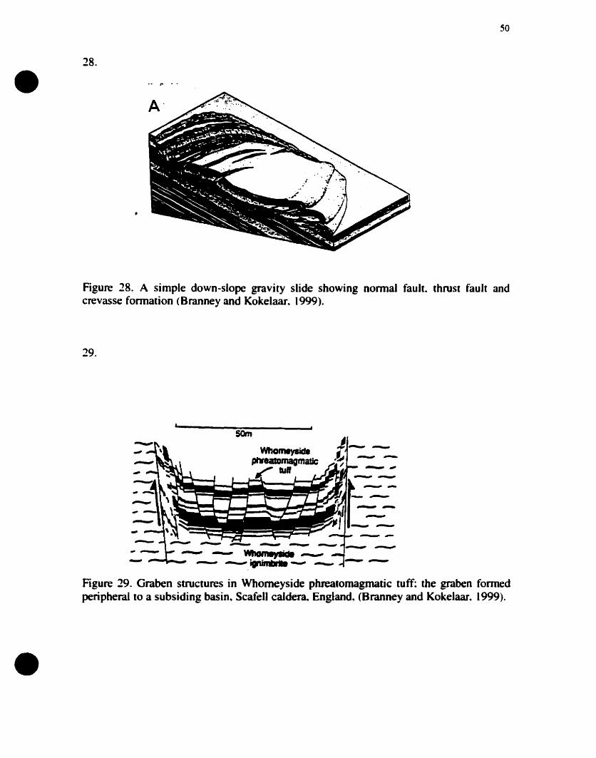
•50
28.
Figure 28. A simple down-slope gravitY slide showing normal fault.. thrust fault andcrevasse formation (Branney and Kokelaar. 1999).
29.
J-_..~ -
/
som
-- --- WIIomep-lfI---"- .......- - ---. igr'ùnIIIrfI8 --- ---...
Figure 29. Graben structures in Whomeyside phreatomagmatic tuff: the graben fonnedperipheral to a subsiding basin. Scafell calder~ England, (Branney and Kokelaar. 1999).
•
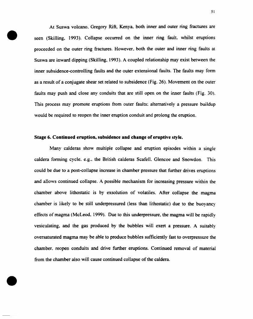
•
•
51
At Suswa volcano. Gregory Rift, Kenya.. both inner and outer ring fractures are
seen (Skilling, 1993). Collapse occurred on the inner ring fault. whilst eruptions
proceeded on the outer ring fractures. However. both the outer and inner ring faults al
Suswa are inward dipping (Skilling, 1993). A coupled relationship may exist between the
inner subsidence-controlling faults and the outer extensional faults. The faults may form
as a result of a conjugate shear set related to subsidence (Fig. 26). Movement on the outer
faults may push and close any conduits that are still open on the ioner fauIts (Fig. 30).
This process May promote eruptions from outer faults; altematively a pressure buildup
would he required to reopen the inner eruption conduit and prolong the eruption.
Stage 6. Continued eruption, subsiden(e and (hange of eruptive style.
Many calderas show multiple collapse and eruption episodes within a single
caldera forming cycle. e.g.• the British calderas ScafelL Glencoe and Snowdon. This
could he due to a post-collapse increase in chamber pressure that further drives eruptions
and allows continued collapse. A possible mechanism for increasing pressure within the
chamber above lithostatic is by exsolution of volatiles. After collapse the magma
chamber is likely to be still underpressured (less than lithostatic) due to the buoyancy
effects of magma (McLeod. 1999). Due to this underpressure, the magma will be rapidly
vesiculating, and the gas produced by the bubbles will exert a pressure. A suitably
oversaturated magma may be able to produce bubbles sufficiently fast to overpressure the
chamber. reopen conduits and drive further eruptions. Continued removal of material
from the chamber also will cause continued collapse of the caldera.
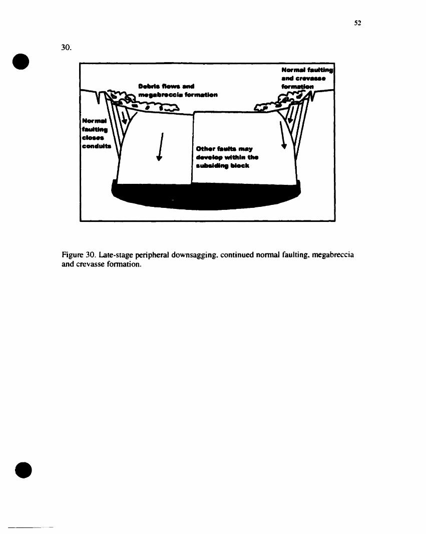
D.II'" tIows .........rece .........
•30.
N .......uItI...c'conduits 1 QtMr fIIulta may
............In ....
.......dI.. 1IIock
N...... flluItI........ cr..-............_-.
iII
52
•
Figure 30. Late-stage peripheraJ downsagging. continued nonnal faulting. megabrecciaand crevasse fonnation.
•
•
53
Further eruptions could be driven by magma interactions with groundwater or
water in a caldera lake. This May have occurred al Ilopango caldera.. El Salvador (J.
Vallance. persona! communication. 2000). Altematively. renewed influxes of magma ioto
the chamber and magma mixing may promote continued eruplion. [n these cases. it is
likely that the subsidence-controlling faults will reactivate. and peripheral extension
features will continue to form. Eruptions again will cease when the conduit closes. and
the pressure at the top of the chamber retums to lithostatic. Collapse also can be
continued by magma withdrawal away from the chamber. with little solid material
erupted. e.g.. Femandina. Galapagos (Chadwick and Dieterich. 1995). Loading from
intrusions and cumulates may have caused progressive collapse of the Hawaiian calderas
(Walker. 1988).
The eruption-collapse sequence may repeat itself severaI times if gas
concentrations in the magma remain sufficiently high after a second pulse of eruplion and
collapse. Vesiculation will again increase the pressure in the magma chamber.
Overpressures cao therefore be developed that further drive eruptions and result in further
subsidence events. Longer periods of time will exist between these eruption and
subsidence events as the magma becomes progressively degassed. As dissolved gas
concentrations decrease in the magma.. it will become progressively more difficuit to
diffuse gas from magma into bubbles. since diffusion times increase significantly as
magma is dewatered (Watson. 1994).
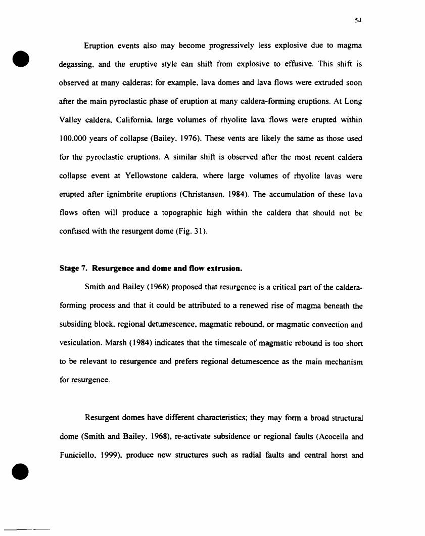
•
•
54
Eruption events aIso may become progressively less explosive due to magma
degassing, and the eruptive style can shift from explosive to effusive. This shift is
observed at many caIderas; for example. lava domes and lava flows were extruded soon
after the main pyroclastic phase of emption at many caldera-forming eruptions. At Long
Valley caIdera. Califomia. large volumes of rhyolite lava flows were erupted within
100,000 years of collapse (Bailey. 1976). These vents are likely the same as those used
for the pyroclastic eruptions. A similar shift is observed after the most recent caldera
collapse event at Yellowstone caldera. where large volumes of rhyolite lavas were
erupted after ignimbrite eruptions (Christansen. 1984). The accumulation of these lava
flows often will produce a topographie high within the caIdera that should not be
confused \vith the resurgent dome (Fig. 31 ).
Stage 7. Resurgenc:e and dome and Oow extrusion.
Smith and Bailey (1968) proposed that resurgence is a critica1 part of the caldera
fonning process and that it could be anributed to a renewed rise of magma beneath the
subsiding block. regionaJ detumescence. magmatic rebound. or magmatic convection and
vesiculation. Marsh (1984) indicates that the timescale of magmatic rebound is too short
to be relevant to resurgence and prefers regional detumescence as the main mechanism
for resurgence.
Resurgent domes have different characteristics; they may fonn a broad structural
dome (Smith and Bailey. (968)~ re-activate subsidence or regional faults (Acocella and
Funiciello. 1999), produce new structures such as radial faults and central horst and
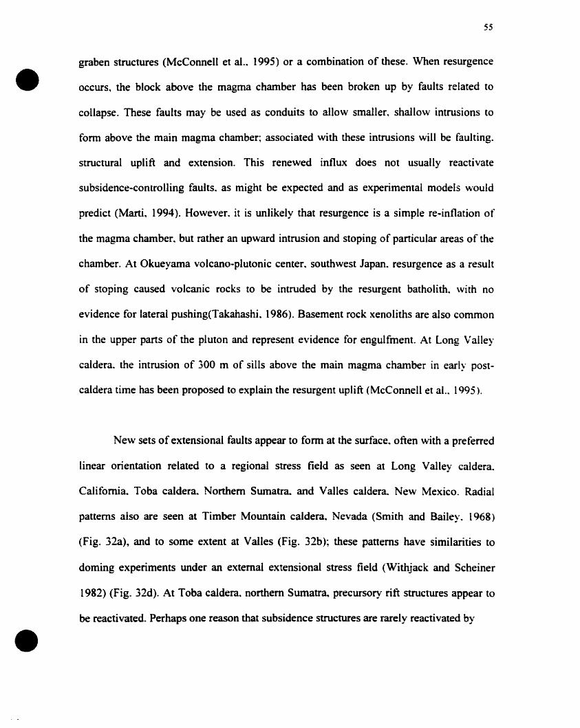
•
•
55
graben structures (McCannell et al.. 1995) or a combination of these. When resurgence
occurs, the black above the magma chamber has been broken up by faults related to
collapse. These faults may be used as conduits to allow smaller. shallow intrusions to
form above the main magma chamber; associated with these intrusions will be faulting.
structural uplift and extension. This renewed influx does not usually reactivate
subsidence-contralling faults. as might be expected and as experimental models wauld
predict (Marti, 1994). However. it is unlikely that resurgence is a simple re-inflation of
the magma chamber. but rather an upward intrusion and stoping of particular areas of the
chamber. At Okueyama volcano-plutonic center. southwest Japan. resurgence as a result
of stoping caused volcanic rocks to be intruded by the resurgent batholith. \Vith no
evidence for lateral pushing(Takahashi. 1986). Basement rock xenoliths are also common
in the upper parts of the pluton and represent evidence for engulfment. At Long Valley
caldera. the intrusion of 300 m of sills above the main magma chamber in early post
caldera time has been prapased to expIain the resurgent uplift (McCannell et al.. 1995).
New sets of extensianal faults appear ta fonn at the surface. often with a preferred
linear orientation related ta a regional stress field as seen at Long Valley caldera.
Califomia. Toba caldera. Northern Sumatra. and Valles caldera. New Mexico. Radial
patterns also are seen at Timber Mauntain caldera, Nevada (Smith and Bailey. 1968)
(Fig. 32a), and ta sorne extent at Valles (Fig. 32b); these patterns have similarities to
doming experiments under an external extensional stress field (Withjack and Scheiner
1982) (Fig. 32d). At Toba caldera. nanhern Sumatra, precursory rift structures appear to
be reactivated. Perhaps one reasan that subsidence structures are rarely reactivated by
•56
uva .......... al_ rt•• fl'actures r fraetllr.. t .........tr....... c r
Figure 31. Pre-resurgence lava effusion along ring fractures and other conduits.
a)
c)
b)
d)
c .,. ' ..
........ .......••
•Figure 32. Comparison between experimental doming and resurgence. a) The TimberMountain resurgent dome (Smith and Bailey.. 1968) b) the Valles resurgent dome (Smithand Bailey, 1968) c) Experimental doming without extension and d) experimentaldoming with extension (Withjack and Scheiner, 1982).
•
•
57
resurgence is because they have become ··sealed" or ··stitched" by minor intrusions. such
as ring dykes and cone sheets. Resurgent doming on the island of Ischia. Italy. has been
strongly Iinked to the regional tectonics of the area where pre-existing normal faults were
reactivated during resurgence (Acocella and Funiciello, 1999).
Effusive events often occur after the main period of resurgence and after a period
of eruptive quiescence. These effusive events often are seen in the moat area of the
caldera between the resurgent dome and the topographie boundary. as at Long Valley and
Valles calderas (Fig. 33). The distribution of these moat domes has been interpreted to
mark a ring fracture (subsidence controlling faults) (Smith and Bailey. 1968). ln theory.
domes would be extruded in areas of extension where faults penetrate to the magma
chamber. e.g.. the peripheral extension outside and concentric to the subsidence
controlling faults (Fig. 34). The main subsidence-controlling faults are likely to be in an
area of compression and may be sealed or stitched by minor intrusions. Therefore. the
interpretation that post-collapse domes and vents mark the main subsidence-controlling
ring fault (Smith and Bailey. 1968) may not always he correct. These domes and vents
instead may fonn in the area peripheral to the main subsidence-controlling fault (Fig. 34).
Another preferential location for extrusions is along regional extensional and
transtensional fissures (Walker. 1984). Where regional structures intersect the resurgent
dome~ effusive eruptive vents may Conn. as at Long Valley caldera. Il is perhaps
surprising that domes are rarely extruded along faults formed by the resurgent dome:
perhaps these do not penetrate sufficiently deep to reach the charnber (Fig. 34).
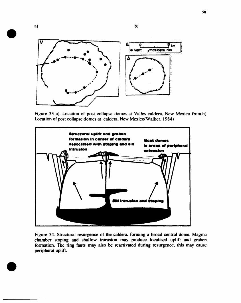
••
a)
v
••,.-e---._......... ,-- " "',,\•;,,,
~,.'. ".--....
1i11
1111
111
i
b)
58
Figure 33 a). wcation of post collapse domes at Valles caldera. New Mexico from.b)Location of post collapse domes at caldera. New Mexico(Waiker. 1984)
Struet upllft .net .' nfo' on 'n e.nter of c ,..uoc'••d wlttl .topa 11'ntruslon
.amdoM"'n .,••• of ........., ..
........on
•
Figure 34. Structural resurgence of the caldera~ forming a broad central dome. Magmachamber stoping and shallow intrusion may produce localised uplift and grabenfonnation. The ring fauts may a1so be reactivated during resurgence. this may causeperipheral uplift.
•
•
59
CHAPTER2
AN EXPERIMENTAL STUDY OF CALDERA FORMATION
General Statement
This experimental study concentrates on only four of the Many variables in the
caldera process.. and investigates the effects of changing these variables on caldera
morphology. The four variables chosen are the depth of the magma chamber. pre-existing
topography above the magma chamber. chamber pressure and chamber orientation. The
depth of the magma chamber was chosen to confirm ideas and mechanisms proposed by
~Iani et al. (1994) and Roche et al. (2000). The effect of pre-existing topography has not
been considered previously al calderas. although Burov and Guillou-Frottier (1999)
illustrate the importance of the loading caused by emplacement of intracaldera ignimbrite
on deformation of the subsiding block. Calderas often torm in regions of high relief. The
loading effect of this relief and its influence on principal stress trajectories likely
influences surface deformation. The effects of magma chamber pressure have been
discussed theoretically (Lipman. 1997; 2000) but require experimental confirnlation.
Lasdy. the orientation of the magma chamber May affect the symmetry of subsidence
(Lipman. 1997; 2000). Our study used a scaled three-dimensional physical model to
investigate these variables. We place emphasis on the relationship between deformation
of the magma chamber and the resultant deformation on the surface (the caldera).
Metbodolocy
Experimental setup
The apparatus comprised a cylinder 0.90 m in diameter and 1 m in height (Fig.
35). The cylinder was filled with unsorted dry sand. Buried within the sand was a 60 cm
diameter rubber bladder filled with water to a maximum capacity of 45 liters. The shape
•
•
60
of the bladder was circular in plan view. with a convex upper and lower surface. so that it
had the shape of an oblate or flattened sphere. When the bladder was near ilS maximum
capacity, it deformed elastically maintaining its overall shape. At lower capacities the
bladder deformed differently. with the upper surface of the bladder flattening. These
different defonnation mechanisms represent the elastic behavior of the crust followed by
brittle faHure. As only 17.7 % of the volume of the bladder was removed. the bladder
never became wrinkled.
The bladder couId be filled and evacuated from a tube attached centrally to its
underside. The evacuation and injection of water into and out of the bladder was
controlled and measured by a flowmeter. In the experiments the bladder was evacuated at
a constant flow rate of 1600 cm3 min· t over a period of 5 minutes. resulting in evacuation
of 8000 cm3• representing 17.7 % of the total volume. This value is similar ta the 10 %
chamber evacuation conservatively estimated by compositional gradient studies (Smith.
(979) and produced calderas of realistic proportions.
The depth. volume and orientation of the bladder could be varied. as weil as the
surface relief. The depth of the bladder was varied between 6.0 and 24 cm. As the width
of the magma chamber was constant. changing the depth could be treated as changing the
aspect ratio (thickness/width) of the subsiding black. However. the convex nature of the
bladder roof prevented these aspect ratios from being compared directly with previous
experiments which used flat chamber roofs (e.g.. Roche et al.. 2000). Aspect ratios in our
experiments varied from about 0.10 to 0.40; these values are minimums. as the roof
thickness was a minimum depth measured from the surface to the top of the convex
bladder. The maximum bladder depth was 10 cm greater at the margins of the bladder.
giving maximum aspect ratios of0.27 to 0.57.
•
•
61
Pre-existing topography was created by building scaled stratocones. ridges and
mountain ranges of sand and placing them in different locations and orientations above
the bladder. A mass of 1 kg of sand was used to produce a 16 cm-diameter and 6 cm-high
stratocone.. 1 kg for the 30 cm-long. 13 cm-wide and 4.3 cm-high ridge. and 5.7 kg for a
58 cm-long. 23 cm-wide and 5 cm-high mountain range.
The volume of the bladder before evaeuation was measured by weight (1 liter of
water = 1 kg) using a simple spring seale. We used two volumes in the experiments. 45
and 40 lîters. By changing the volume of the bladder. we changed its internai pressure.
The larger volume simulated collapse into an overpressured.. closed-system magma
chamber. while the smaller volume represented an open-system magma ehamber "vith
liule overpressure. Pressure within a closed magma chamber will build up and then be
released after eruption: this release of pressure may cause elastic contraction of the crust.
This effect will not be seen in a more open system.
The bladder could be tilted to simulate a magma chamber whieh was higher in
one area than another, in order to test ideas about asymmetric collapse (Lipman. (997).
The orientation and minimum depth of the bladder was monitored using a dipstiek and
grid (Fig. 36). This allowed the bladder orientation to be kept constant when the depth.
volume or topography was being varied. The same method was used to measure the relief
of the caldera and the magma chamber after the collapse. Depths were measured every 5
cm on the x and y a.xes, except where the topography was complex, in whieh case depths
were measured every 2.5 cm.
Two lasers were positioned at right angles to each other and inc1ined at an angle
of 30.5 degrees from the horizontal to produce lines that formed a eross on the planar
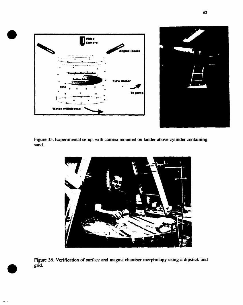
62
To,...,
..........r
--_ .... '-
•• • •
' ••• 11 .........
C;;_.'•
•
•
- - ---~-. .'-----.__-:.~~c-w--
•
•
•~-.r-._ ·l "~-. • --.-" -- l. . .
--..._--------=.~
....r"tlNlr.... ""-,
•
Figure 35. Experimental setup. with camera mounted on ladder above cylinder containingsand.
•Figure 36. Verification of surface and magma chamber morphology using a dipstick andgrid .
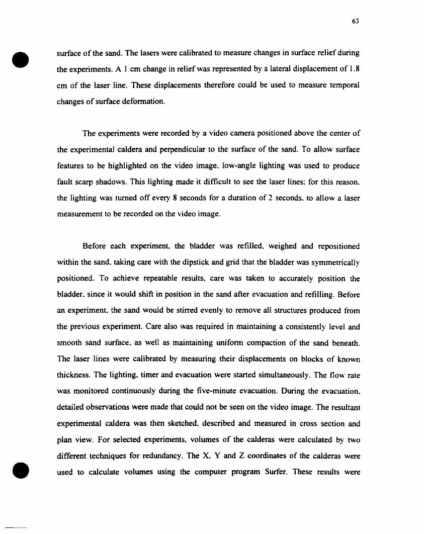
•63
surface of the sand. The lasers were calibrated to measure changes in surface relief during
the experiments. A 1 cm change in relief \vas represented by a lateral displacement of 1.8
cm of the laser line. These displacements therefore could he used to measure temporal
changes of surface deformation.
The experiments were recorded by a video camera positioned above the center of
the experimental caldera and perpendicular to the surface of the sand. To allow surface
features to be highlighted on the video image. low-angle lighting was used to produce
fault scarp shadows. This lighting made it difficult to see the laser Hnes: for this reason.
the lighting was turned off every 8 seconds for a duration of 2 seconds. to allow a laser
measurement to be recorded on the video image.
Before each experiment. the bladder was refilled. weighed and repositioned
within the sand. taking care with the dipstick and grid that the bladder was symmetrically
positioned. To achieve repeatable results. care was taken to accurately position the
bladder. since it would shift in position in the sand after evacuation and refilling. Before
an experiment. the sand would be stirred evenly to remove ail structures produced from
the previous experiment. Care also was required in maintaining a consistently level and
smooth sand surface.. as weil as maintaining uniform compaction of the sand beneath.
The laser lines were calibrated by measuring their displacements on blocks of known
thickness. The Iighting. timer and evacuation were started simultaneously. The flo\\" rate
was monitored continuously during the five-minute evacuation. During the evacuation.
detailed observations were made that could not be seen on the video image. The resultant
experimental caldera was then sketched, described and measured in cross section and
plan view. For selected experiments., volumes of the calderas were calculated by two
different techniques for redundancy. The X.. Y and Z coordinates of the calderas were
• used to calculate volumes using the computer program Surfer. These results were
•64
confirmed by gradually filling the caldera with a known volume of sand. The results of
the two techniques agreed to within 3 0/0. Each experiment was repeated three or four
times producing similar results. The most representative experiment was then chosen for
detailed analysis.
The volume evacuated from the chamber was greater than the volume of the
caldera. A volume of 8000 cm3 of water was removed from the bladder in every
experiment. while caldera volumes varied from 6140 to 3880 cm3• These large
differences result from sand being dilatant during evacuation. causing substantial
increases in porosity.
Scaling of variables
For an analogue model to represent reality. certain scaling considerations are
required. Both geometric and dynamic similarity is necessary between the model and
nature. Ratios are used to help maintain this similarity (Sanford. (959).
Calderas have diameters varying from more than 50 km down to 2 km (Branney.
1995). The experimental setup could be no larger than 1 m x 1 m x 1 m. due to
constraints of the large weight of tbis volume of sand. For this reason, a 50 cm-diameter
experimental caldera represents a 20 km-diameler caldera:
Max. diameter of model = 0.5 m = 2.5 x 10⁻⁵
Max. diameter ofcaldera 20.000 m
A length ratio (L*) of 2.5 x 10⁻⁵ was therefore used. allo\\ing the analogue model
to bave a larger size than previous caldera models (Komuro 1984, 1987; Marti et al..
1994; Odonne et al.~ 1999; Roche et al., 2000). Caldera dimensions. surface topography
• and bladder depths were scaled using this ratio.
•65
The scaling of crustal rock and magma to experimental materials also was
determined. The densities, viscosities and cohesions of the experimental materials needed
to be considered. Cohesion was scaled using the stress ratio(cr*). which is a product of
the length ratio (L*). the gravity ratio (g.) and the density ratio (p.):
cr* = p*g·L· = 1.8- 2.4 x 10⁻⁵
where the density ratio p. == 0.95-0.70 (uncompacted sand used in experiments 1890 kg
m-3 .. naturai rock 2000-2700 kg/m-3) and the gravity ratio g* = 1 (both experimental and
natural calderas fonn under the same gravity conditions).
The cohesion of volcanic rock (equivalent scaling ratio to cr*) is on the order of
107 Pa (10 MPa); this means that the model should have cohesion values of around 100-
200 Pa. However. on a larger scale. jointing and fracturing reduce the cohesion of
volcanic rock to about 106 Pa (Schultz.. 1996).. so the model should have a cohesion of 10
20 Pa. Although in theory well-sorted dry sand has no cohesion. the sand used in the
experiments was poorly sorted and contained moisture absorbed from the air. Attempts
were made to measure the sand cohesion using shear box tests. but it was difficult to
accurately measure such low cohesion values. As a result. the sand can only be said to
have a cohesion of 0-100 Pa, which is appropriate to the scaled cohesion of volcanic rock
containing sorne fractures. As sand and rock are in theory Coulomb materials.. varying
timescales should not affect the defonnation. Sorne preliminary shear box tests on the
sand showed that time may in fact influence the resultant deformation in pure dry sand:
this could he a result of compaction.
The time ratio is based on 5 minutes evacuation time.. representing eight days for
• a large caldera to fonn in nature (Wilson and Hildreth~ 1997):
•66
CoUapse lime ratio t* =: 300 seconds = 300 = 4.34 x 10⁴
8 days 691200
Other scaling ratios that may need consideration are viscosity of the magma and
velocity of magma evacuation. These will be important if the deformation of the sand is
found to be time-dependent. A simple way to define a viscosity ratio was used:
Viscosity ratio (Jla) =t*L* =10.8
Viscosities in magmas have been calculated to vary over 16 orders of magnitude.
from 102 Pa s for basait to in excess of 10 18 Pa s for anhydrous rhyolite (Hess and
DingwelI. 1996); this creates a problem for scaling. A mean value of around lOI! Pa s
indicates a very low viscosity is required for the analogue model. The water in the
bladder has a viscosity of less than 1 Pa s. which seems appropriate.
Relevanee and Limitations
The experimental calderas that were produced can never accurately reproduce the
complex process of caldera formation. However. the experiments do provide insights into
the manner by which a block of homogeneous crust May defonn when subsiding into a
shallow oblate magma chamber. A large proportion of the structures seen al cald~ras is
associated with this process. However, structures produced by the complex proct:sses 0 f
magma intrusion and resurgence could not be reproduced in our experiments. A150. many
calderas have undergone a complex collapse history, as represented by several caldera
cycles and multiple collapse episodes within these cycles. Our experiments represent only
a single collapse event. However, Many aspects of the structures seen in the experiments
• still have relevance to these complex systems.
•67
Our experimental model has certain restrictions. Although sand can deform in a
brittle manner and has appropriate cohesion values, its granular nature allows granular
flow that does not occur in rigid rocks. The granular nature of sand also produces
problems of compaction. A subsiding block of sand will expand, increasing its volume
and porosity, thereby changing its compaction. In a subsiding caldera. compaction effects
are likely to be minor. A further problem with using a granular material is its angle of
repose of 300; natural rock cao remain stable to much higher angles. This implles that
fault scarps greater than 30 0 cannot be created in our experiments. whereas calderas in
nature frequently have scarps that are steeper.
There are also sorne problems with using a water-filled rubber bladder to
represent a magma chamber. The rubber bladder containing the water represents a
boundary that is not present in nature. This boundary prevents subsiding blacks l'rom
descending into the chamber. Il also prevents upward intrusion and stoping of the magma
between foundering blocks. Scaling restrictions in terms of viscosity support the use of
water in the bladder to represent magma. Il is also an incompressible fluid. and ilS
physical properties appear appropriate. However. gas bubbles may exist in magma.
making it partIy compressible.
The recent thermomechanical model developed by Burov and Guillou-Frottier
( (999) indicates the importance of intracaldera ignimbrite and the geothermal gradient on
the properties of rocks around the chamber. Neither of these factors were considered in
our analogue model. There are also sorne unresolved scaling problems related to the
amount of overpressure within the chamber.
Despite these constraints, the experiments produced repeatable resuits which
• showed many features that can be observed al calderas. We have carefully constructed
•68
our experimental setup in order to eliminate Many of the problems encountered in
previous experimental studies. such as inappropriate chamber deformation and viscosities
of experimental liquids. We therefore believe that our experimental approach is a good
approximation of caldera fonnation.
Results
The results presented here are a representative selection of the experiments
undertaken. Type experiments were chosen to show the range of experiments carried out.
Type experiments for different depths. topography. pressure and chamber symmetry are
discussed in detail below. Using the video footage of the experiments. temporal surface
observations of each type experiment are described. The most important observational
trends for each set of experiments are then presented.
Depth
ln the depth experiments. the surface was always smooth and horizontal. the
bladder volume was kept constant at 45 liters and the bladder was oriented horizontally.
Experiment 78: depth 6.0 cm (2.5 km>.
ln this experiment surface deformation began by symmetric sag that formed
above the center of the bladder. This sag became more asymmetric. and the tirst fault was
seen at the surface in the southwest after 2 min 43 s (Fig. 37. 3 min). Subsidence was
greatest associated with this fault. whereas the remaining subsidence was controlled by
sagging. The main fault developed in a curve laterally outward from the area of
maximum subsidence. ûther small linear faults developed both inside and outside this
main fault. which produced a complex fault pattern in the area of maximum subsidence.
• After 3 min 50 s a second fault also developed in the southwest corner 15 cm outside the
•
•
69
first fault and concentric to it. This fault developed in the same way as the first ..
developing as a curve gro\ving outward from the southwest corner (Fig. 37.. 5 min). It had
only a smali amount of subsidence associated with il. Both faults remained active until
the end of the experiment but never progressed beyond the southwest quadrant. This
resulted in a highly asymmetric depression both in cross-section and plan view. At the
base of the fault scarp a small terrace developed (Fig. 37. 5 min). Sagging controlled the
subsidence in most of the depression and reached a maximum diameter of 80 cm. The
main semi-circular inner fault reached a diameter of24 cm.
Experiment 38: depth 9.5 cm (3.75 km>
Surface deformation began with a symmetric sag above the center of the bladder.
After 1 min 55 s.. a 3 cm-diameter horseshoe-shaped fault developed in the center of the
sag. Subsidence on this fault was limited (Fig. 38.. 3 min). After 2 min 20 s. subsidence
shifted.. and two faults began to develop simultaneously in the north and in the west: both
were initially linear but propagated toward each other. Curved corner faults formed in the
north. south and west. On the southwestem margin.. two parallel faults formed. and a
terrace developed between the two. These faults then joined with the southem corner and
the northwestem side and formed a coherent ring structure (Fig. 38. 4 min). After 4 min
30 s.. arcuate outer fault structures began to develop in the north.. west and southeast
located 10-20 cm outside the main fault. This principal structure was not circular in plan
view; it instead consisted of four sides with four distinct corners. two faults bounding the
southwestem side and its diameter varying from 30 cm to 45 cm. Sagging reached a
diameter of65 cm.
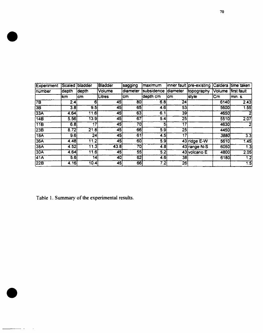
•
•
70
Experiment Scaled bladder 81adder sagging maximum inner fault pre-existing Caldera time takennumber depth depth Volume diameter subsidence diameter topography Volume first fault
km cm Litres cm depth cm cm style Cm min. s.78 2.4 6 45 80 6.8 24 6140 2.4338 3.8 9.5 45 65 4.6 53 5600 1.5533A 4.64 11.6 45 63 6.1 39 4650 2148 5.56 13.9 45 67 5.4 25 5510 2.07118 6.8 17 45 70 5 17 4630 2238 8.72 21.8 45 66 5.9 25 445018A 9.6 24 45 61 4.5 17 3880 3.336A 4.48 11.2 45 60 5.9 43 ridge E-W 5610 1.4538A 4.52 11.3 43.8 70 4.8 43 range N-S 6050 1.330A 4.64 11.6 45 55 5.2 43 volcano E 4800 2.0541A 5.6 14 40 62 4.6 38 6180 1.2228 4.16 10.4 45 66 7.2 26 1.5
Table 1. Summary of the experimental results.
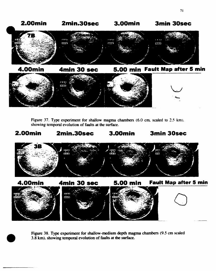
2.00min 2min.30sec 3.00min
71
3min 30sec
4.00min 4mln 30 sec 5.00 min Fault Map after 5 min
Figure 37. Type experiment for shallow magma chambers (6.0 cm. scaled to 2.5 km).showing temporal evolution of faults al the surface.
2.00min 2min.30sec 3.00min 3min 30sec
4.00min 4mln 30 sec 5.00 min Fault Map alter 5 min
a
• Figure 38. Type experiment for shallow-medium depth magma chambers (9.5 cm scaled3.8 km). showing temporal evolution offaults at the surface.
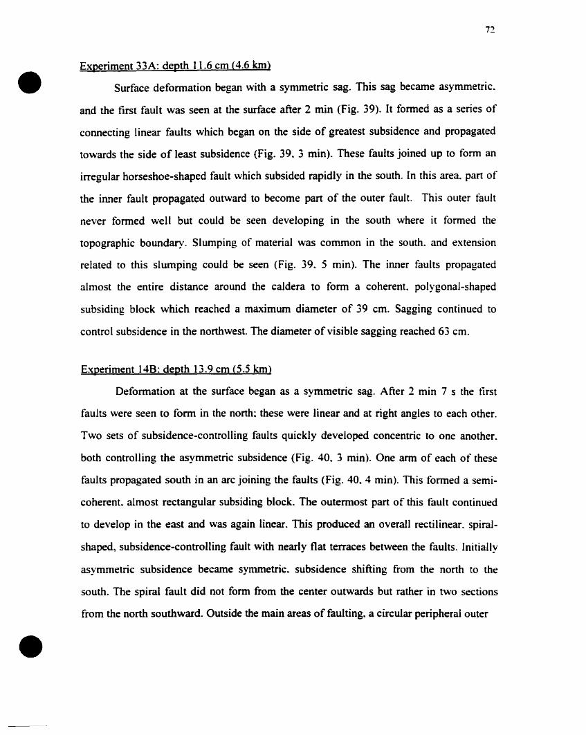
•
•
72
Experiment 33A: depth 11.6 cm (4.6 km>
Surface defonnation began with a symmetric sag. This sag became asymmetric.
and the tirst fault was seen at the surface after 2 min (Fig. 39). It formed as a series of
connecting linear faults which began on the side of greatest subsidence and propagated
towards the side of least subsidence (Fig. 39. 3 min). These faults joined up to fonn an
irregular horseshoe-shaped fault which subsided rapidly in the south. [n this area. part of
the inner fault propagated outward to become part of the outer fault. This outer fault
never fonned weIl but could be seen developing in the south where it formed the
topographie boundary. Slumping of material was common in the south. and extension
related to this slumping could be seen (Fig. 39. 5 min). The inner faults propagated
almost the entire distance around the caldera to form a coherent. polygonal-shaped
subsiding block which reached a maximum diameter of 39 cm. Sagging continued to
control subsidence in the northwest. The diameter of visible sagging reached 63 cm.
Experiment 148: depth 13.9 cm (5.5 km)
Deformation at the surface began as a symmetric sag. After 2 min 7 s the tirst
faults were seen to fonn in the north; these were Iinear and at right angles to each other.
Two sets of subsidence-controlling faults quickly developed concentric to one another.
both controlling the asymmetric subsidence (Fig. 40. 3 min). One arm of each of these
faults propagated south in an arc joining the faults (Fig. 40. 4 min). This formed a semi
coherent. almost rectangular subsiding block. The outermost part of this fault continued
to develop in the east and was again linear. This produced an overall rectilinear. spiral
shaped, subsidence-controlling fauit with nearly fiat tenaces between the faults. InitiaJly
asymmetric subsidence became symmetric. subsidence shifting from the north to the
south. The spiral fault did not form from the center outwards but rather in two sections
from the north southward. Outside the main areas of faulting. a circular peripheral outer
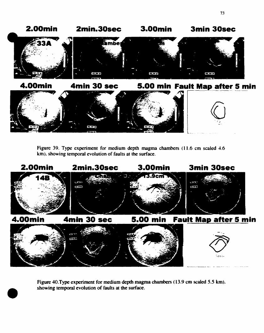
2.00min 2min.30sec 3.00min
73
3min 30sec
4.00mln 4mln 30 sec 5.00 min FaUr~e~.5 min
l .:-"
•
Figure 39. Type experiment for medium depth magma chambers (11.6 cm scaled 4.6km). showing temporal evolulion of faults al the surface.
2min.30sec 3min 30sec
5.00 min Fault Map after 5 min
~_._-- - --~_. ~. --_.--
Figure 40.Type experiment for medium depth magma chambers (13.9 cm scaled 5.5 km).showing temporal evolution of faults al the surface.
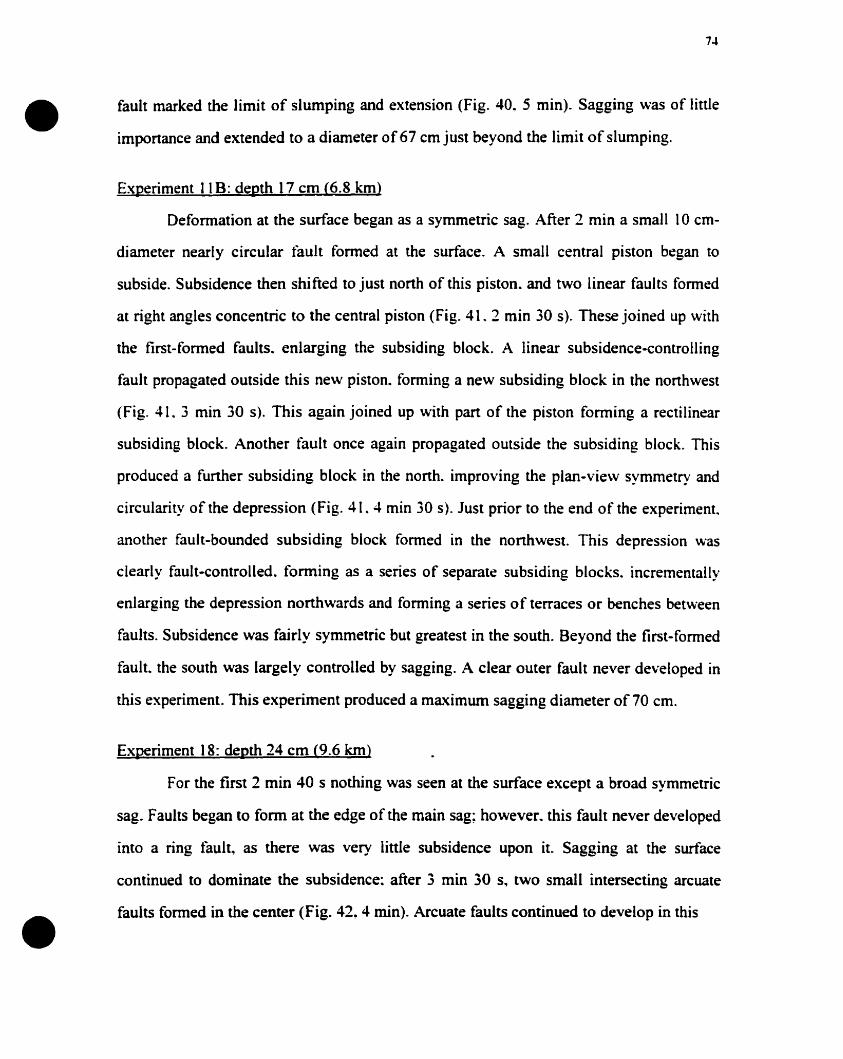
•
•
74
fault marked the limit of slumping and extension (Fig. 40. 5 min). Sagging was of litde
importance and extended ta a diameter of67 cm just beyond the limit of slumping.
Experiment Il B: depth 17 cm (6.8 km>
Deformation at the surface began as a symmetric sag. After 2 min a small 10 cm
diameter nearly circular fault formed at the surface. A small central piston began to
subside. Subsidence then shifted ta just north of this piston. and two linear faults formed
at right angles concentric to the central piston (Fig. 41. 2 min 30 s). These joined up with
the first-formed faults. enlarging the subsiding black. A linear subsidence-controlling
fault propagated outside this new piston. forming a new subsiding block in the northwest
(Fig. 41. 3 min 30 s). This again joined up with part of the piston fonning a rectilinear
subsiding block. Another fauft once again prapagated outside the subsiding block. This
produced a further subsiding block in the north. improving the plan-view symmetry and
circularity of the depression (Fig. 41. 4 min 30 s). Just prior to the end of the experiment.
anather fault-bounded subsiding black formed in the nonhwest. This depression was
clearly fault-cantralled. fonning as a series of separate subsiding blacks. incrementally
enlarging the depression northwards and forming a series of terraces or henches between
faults. Subsidence was fairly symmetric but greatest in the south. Beyond the first-farmed
fault. the south was largely controlled by sagging. A c1ear outer fault never developed in
this experiment. This experiment produced a maximum sagging diameter of 70 cm.
Experiment 18: depth 24 cm (9.6 km>
For the tirst 2 min 40 s nothing was seen at the surface except a broad symmetric
sag. Faults began to form at the edge of the main sag; however. this fault never developed
iota a ring fault~ as there was very linle subsidence upon it. Sagging at the surface
continued to dominate the subsidence: after 3 min 30 s~ two small intersecting arcuate
faults formed in the center (Fig. 42, 4 min). Arcuate faults continued to develop in this
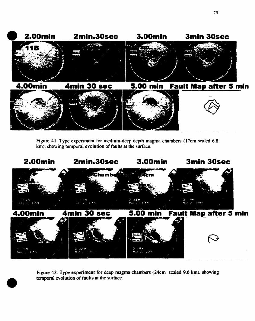
2.00min
4.00min
2min.30sec
4min 30 sec
75
3.00min 3min 30sec
5.00 min Fault Map after 5 min
Figure 41. Type experiment for medium-deep depth magma chambers (17cm scaled 6.8km). showing temporal evolution of faults at the surface.
2.00min 2min.30sec 3.00min 3min 30sec
4.00min 4min 30 sec 5.00 min Fault Map after 5 min
•Figure 42. Type experiment for deep magma chambers (24cm scaled 9.6 km).. showingtemporal evolution of faults at the surface.
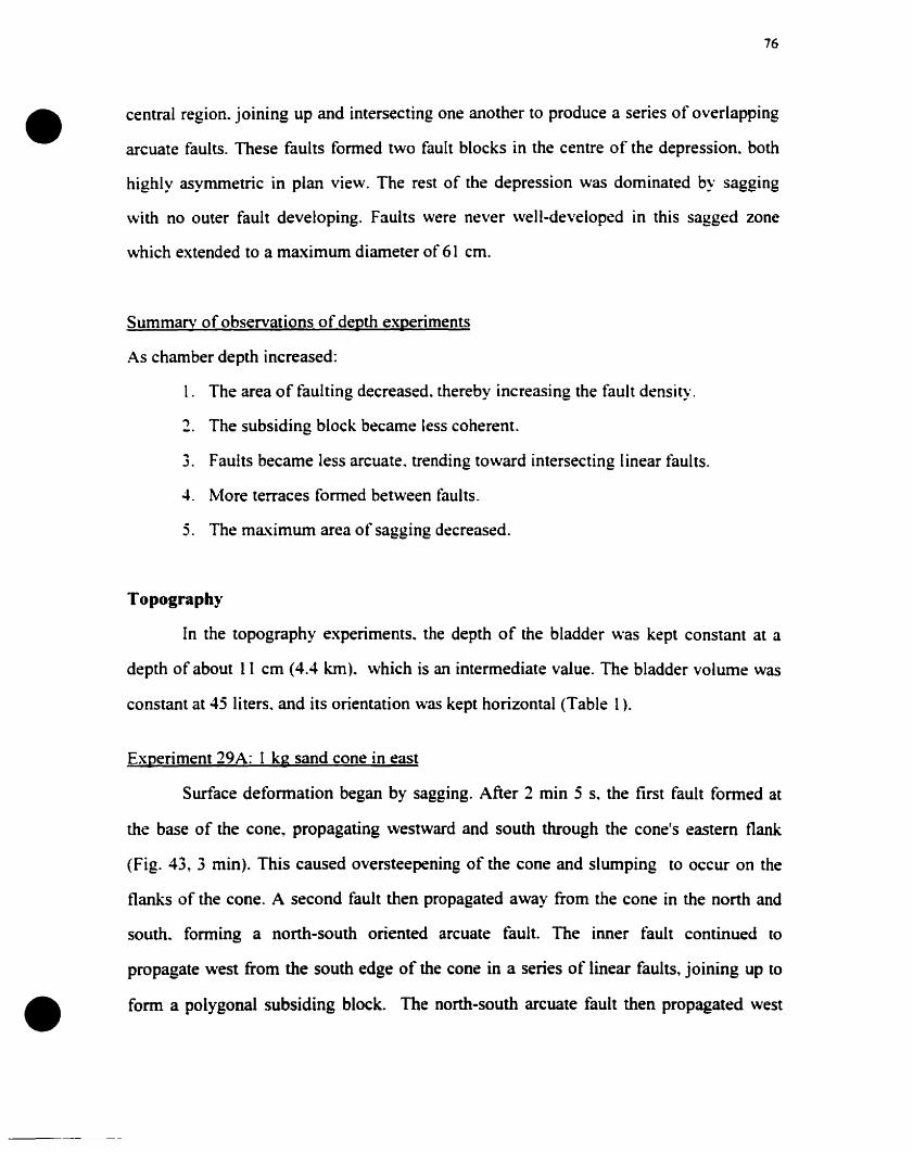
•76
central region. joining up and intersecting one another to produce a series of overlapping
arcuate faults. These faults formed two fault blocks in the centre of the depression. both
highly asymmetric in plan view. The rest of the depression was dominated by sagging
with no outer fault developing. Faults were never well-developed in this sagged zone
which extended to a maximum diameter of 61 cm.
Summarv of observations of depth experiments
As chamber depth increased:
1. The area of faulting decreased. thereby increasing the fault density.
~ The subsiding block became less coherent.
3. Faults became less arcuate. trending toward intersecting linear tàults.
4. More terraces formed between faults.
5. The maximum area of sagging decreased.
Topography
In the topography experiments.. the depth of the bladder was kept constant at a
depth of about Il cm (4.4 km). which is an intermediate value. The bladder volume was
constant at 45 lïters. and its orientation was kept horizontal (Table 1).
Experiment 29A: 1 kg sand cone in east
Surface defonnation began by sagging. After 2 min 5 s.. the first fault fonned at
the base of the cone" propagating \vestward and south through the cone's eastem flank
(Fig. 43, 3 min). This caused oversteepening of the cone and slumping to occur on the
flanks of the cone. A second fault then propagated away from the cone in the nonh and
south.. fonning a north-south oriented arcuate fault. The inner fault continued to
propagate west from the south edge of the cone in a series of linear faults. joining up to
• fonn a polygonal subsiding block. The north-south arcuate fault then propagated west
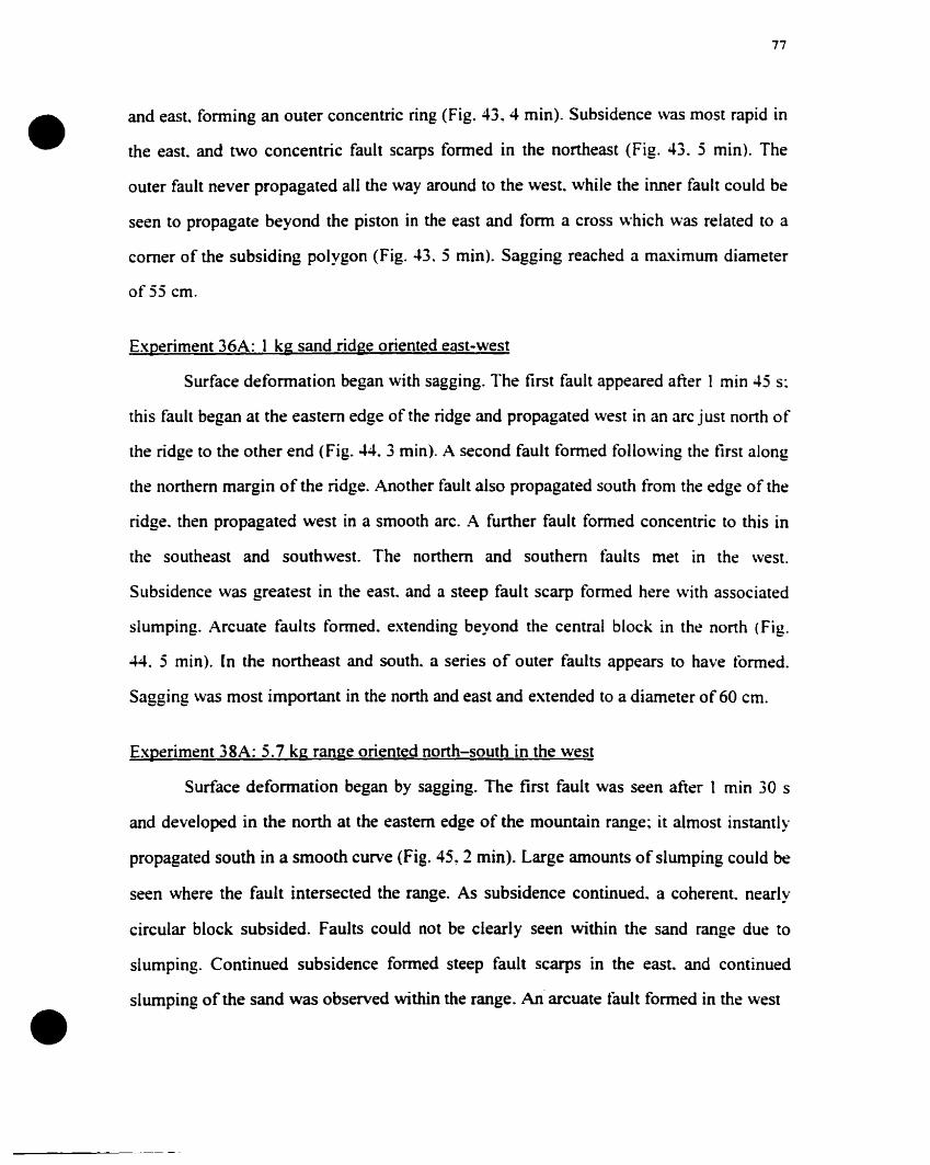
•
•
77
and east. forming an outer concentric ring (Fig. 43.4 min). Subsidence was most rapid in
the east. and two concentric fault scarps formed in the northeast (Fig. 43. 5 min). The
outer fault never propagated ail the way around to the \vest.. while the inner fault could be
seen ta propagate beyond the piston in the east and fonn a cross which was related to a
corner of the subsiding polygon (Fig. 43. 5 min). Sagging reached a maximum diameter
of 55 cm.
Experiment 36A: 1 kg sand ridge oriented east-west
Surface deformation began with sagging. The tirst fault appeared after 1 min 45 s:
this fauft began at the eastern edge of the ridge and propagated west in an arc just nonh of
the ridge to the other end (Fig. 44. 3 min). A second fault formed following the tirst along
the nonhern margin of the ridge. Another fault also propagated south from the edge of the
ridge. then propagated west in a smooth arc. A further fault formed concentric to this in
the southeast and southwest. The northem and southern faults met in the west.
Subsidence was greatest in the east. and a steep fault scarp formed here with associated
slumping. Arcuate faults formed. extending beyond the central block in the north (Fig.
44. 5 min). [n the northeast and south. a series of outer faults appears to have tormed.
Sagging \Vas most important in the nonh and east and extended to a diameter of60 cm.
Experiment 38A: 5.7 kg range oriented north-south in the west
Surface deformation began by sagging. The first fault was seen after 1 min 30 s
and developed in the north at the eastem edge of the mountain range~ it almost instantly
propagated south in a smooth curve (Fig. 45, 2 min). Large amounts of slumping could he
seen where the fauIt intersected the range. As subsidence continued. a coherent.. nearly
circular block subsided. Faults could not be clearly seen within the sand range due to
slumping. Continued subsidence formed steep fault scarps in the east.. and continued
slumping of the sand was observed within the range. An arcuate tàult formed in the west
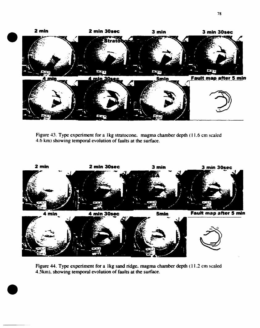
• 2 min 2 min 30sec 3 min
78
3 min 30see
Figure 43. Type experiment for a Ikg stratocone.. magma chamber depth (11.6 cm scaled4.6 km) showing temporal evolution of faults at the surface.
-~
4 minr?' ...r ..
2 min 30see
4 ...In 30sec-_. ~
3 min
Smln
3 min 30sec
Fault map after 5 min
•Figure 44. Type experiment for a 1kg sand ridge.. magma chamber depth (11.2 cm scaled4.5km),. showing temporal evolution of faults al the surface.
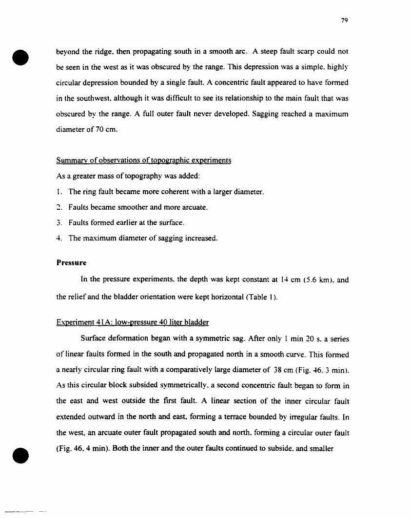
•
•
79
beyond the ridge. then propagating south in a smooth arc. A steep fault scarp could not
be seen in the west as it was obscured by the range. This depression was a simple. highly
circular depression bounded by a single fault. A concentric fault appeared to have tormed
in the southwest. although it was difficult to see its relationship to the main fault that was
obscured by the range. A full outer fault never developed. Sagging reached a maximum
diameter of 70 cm.
Summarv of observations of topographie experiments
As a greater mass of topography was added:
1. The ring fault became more coherent with a larger diameter.
") Faults became smoother and more arcuate.
3. Faults formed earHer at the surface.
4. The maximum diameter of sagging increased.
Pressure
ln the pressure experiments. the depth was kept constant at 14 cm (5.6 km). and
the relief and the bladder orientation were kept horizontal (Table 1).
Experiment 41 A: low-pressure 40 liter bladder
Surface deformation began with a symmetric sag. After only 1 min 20 s. a series
of linear faults formed in the south and propagated north in a smooth curve. This fonned
a nearly circular ring fault with a comparatively large diameter of 38 cm (Fig. 46. 3 min).
As this circular block subsided symmetrically. a second concentric fault began to fonn in
the east and west outside the rust fault. A linear section of the inner circular fault
extended outward in the north and east, fonning a tenace bounded by irregular tàults. In
the west, an arcuate outer fault propagated south and north.. fonning a circular outer fault
(Fig. 46, 4 min). 80th the inner and the outer faults continued to subside. and smaller
• 2 min
80
F.ull m.p ....r 5 min.. ~ - - - --- --- --._-
ùFigure 45. Type experiment for a 5.7 kg sand range. magma chamber depth (11.3 cmscaled 4.5 km). showing temporal evolution of faults at the surface.
3 min 30..c
1min 30sec 2 min 2 ...in 30sec 3 min
F.un ...........r5min
Figure 46. Type experiment for a low pressure 40 liter bladder. chamber depth (l4cmscaled 5.6 km), showing temporal evolution of faults at the surface.
•
•
81
extensional fractures developed between the two faults in the south. The subsided block
was horizontal. and sagging only extended to 62 cm.. being most important in the
northeast where the outer circular fault was poorly developed. The central subsiding
block appeared to be completely coherent. Subsidence was slightly asymmetric. being
greatest in the south where faults first formed.
Summarv of low-pressure experiments
Compared to the higher-pressure experiments. the low-pressure experiments showed:
1. The subsiding block had a larger diameter and appeared to be more coherent.
., Sagging was of smaller diameter.
3. Faults were less linear and formed nearly circular ring structures.
Tilted chamber
In the tilted bladder experiments. the depth was kept constant at 10.4 cm (4.2 km).
as measured from the surface to the highest point of the bladder. the surface was always
smooth and horizontal. and the bladder volume was constant at 45 Hters (Table 1).
Experiment 228: Tilted bladder elavated in the northeast
Surface deformation began by sagging, which was almost immediately
asymmetric. subsiding faster in the north and east (Fig.47, 2 min). After 1 min 50 s a
series of poorly-developed faults formed first in the northeast.. then in the east and south
(Fig. 47, 2 min 30 s). Linle subsidence occurred on these faults. and sagging increased
rapidly in the west and south, with linear faults forming in these areas. These faults
joined up with the earlier-formed faults to form a rectangular northeast-southwesl
oriented subsiding block (Fig. 47. 3 min). Subsidence became rapid in the south and west.
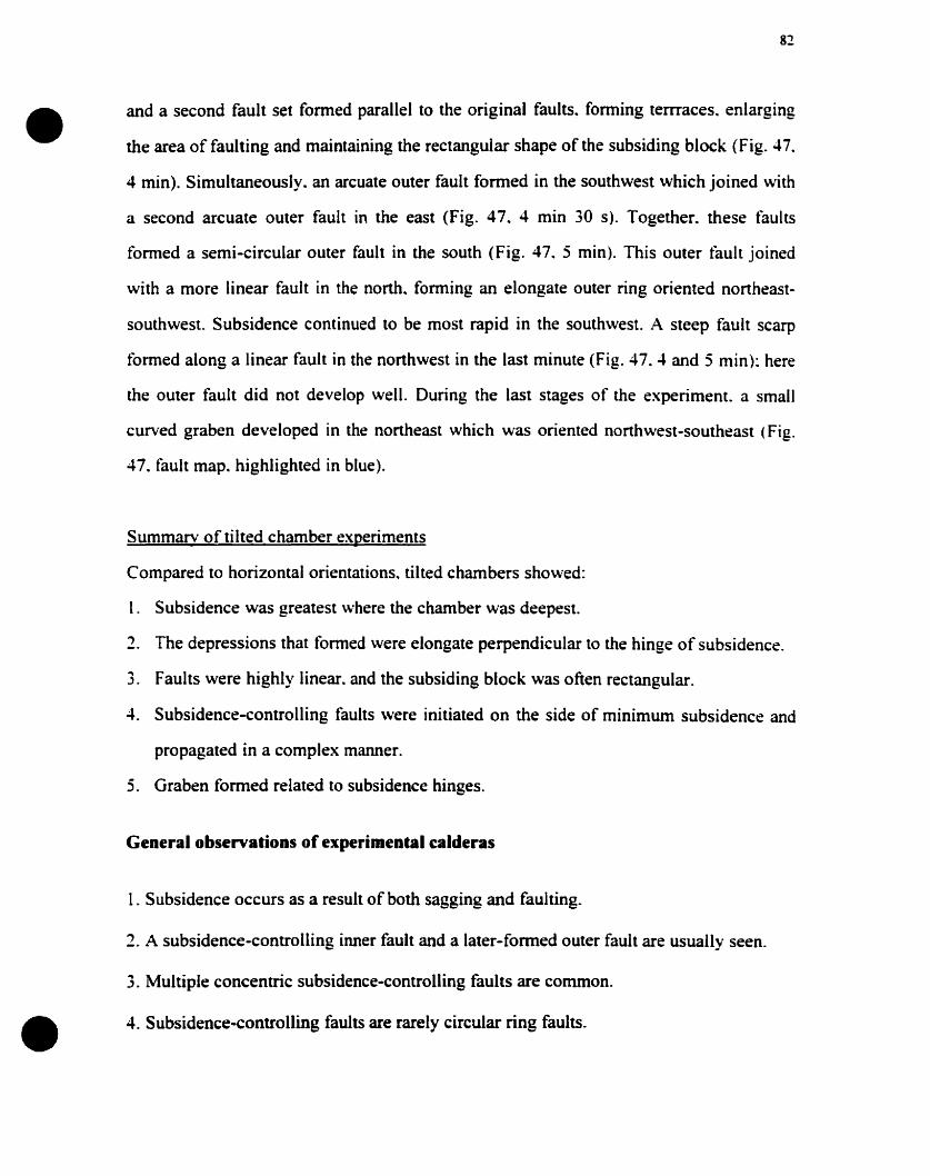
•
•
82
and a second fault set formed parallei to the original faults. fonning temaces. enlarging
the area of faulting and maintaining the rectangular shape of the subsiding block (Fig. 47.
4 min). Simultaneously. an arcuate outer fault fonned in the southwest which joined with
a second arcuate outer fault in the east (Fig. 47. 4 min 30 s). Together. these tàults
formed a semi-circular outer fault in the south (Fig. 47. 5 min). This outer fault joined
with a more linear fault in the north. forming an elongate outer ring oriented northeast
southwest. Subsidence continued to be most rapid in the southwest. A steep fault scarp
formed along a linear fault in the northwest in the last minute (Fig. 47.4 and 5 min): here
the outer fault did not develop weil. During the last stages of the experiment. a small
curved graben developed in the northeast which was oriented northwest-southeast (Fig.
47. fault map. highlighted in blue).
Summarv oftilted chamber experiments
Compared to horizontal orientations. tilted chambers showed:
1. Subsidence was greatest where the chamber was deepest.
2. The depressions that formed were elongate perpendicular to the hinge of subsidence.
3. Faults were highly linear. and the subsiding block was often rectangular.
4. Subsidence-controlling faults were initiated on the side of minimum subsidence and
propagated in a complex manner.
5. Graben formed related to subsidence hinges.
General observations of experimental calderas
1. Subsidence occurs as a result ofboth sagging and faulting.
2. A subsidence-controlling inner fault and a later-fonned outer fault are usually seen.
3. Multiple concentric subsidence-controlling faults are common.
4. Subsidence-controlling faults are rarely circular ring faults.
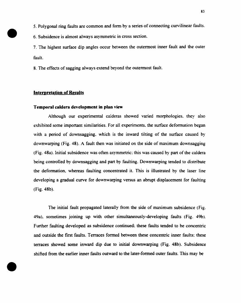
•
•
83
5. Polygonal ring faults are common and form by a series of connecting curvilinear faults .
6 Subsidence is almost alwavs asvmmetric in cross section.. .. .
7. The highest surface dip angles occur between the outermost inner fault and the outer
fault.
8. The effects of sagging always extend beyond the outermost fault.
Intemretation of Results
Temporal caldera development in plan view
Although our experimental calderas showed varied morphologies. they also
exhibited sorne important similarities. For all experiments. the surface deformation began
with a period of downsagging. which is the inward tilting of the surface caused by
do\vnwarping (Fig. 48). A fault then was initiated on the side of maximum downsagging
(Fig. 48a). Initial subsidence \Vas often asymmetric: this \Vas caused by part of the caldera
being controlled by downsagging and part by faulting. Downwarping tended to distribute
the defonnation. whereas faulting concentrated it. This is illustrated by the laser Hne
developing a graduai curve for downwarping versus an abrupt displacement for tàulting
(Fig. 48b).
The initial fault propagated laterally from the side of maximum subsidence (Fig.
49a). sometimes joining up with other simultaneously-developing faults (Fig. 49b).
Further faulting developed as subsidence continued: these faults tended ta be concentric
and outside the tirst faults. Terraces formed between these concentric inner faults: these
terraces showed sorne inward dip due to initial downwarping (Fig. 48b). Subsidence
shifted from the earlier inner faults outward to the later-formed outer faults. This May be
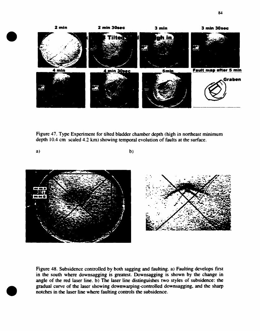
•2 min 2 min 30..c 3 min
84
3 min 3Gsec
Figure 47. Type Experiment for tilted bladder chamber depth (high in nonheast minimumdepth 10.4 cm scaled 4.2 km) showing temporal evolution of faults at the surface.
a) b)
•Figure 48. Subsidence controlled by both saggjng and faulting. a) Faulting develops tirstin the south where downsagging is greatest. Downsagging is shown by the change inangle of the red laser line. b) The laser line distinguishes IWO styles of subsidence: thegraduai curve of the laser showing downwarping-controlled downsagging. and the sharpnotches in the laser line where faulting controls the subsidence.
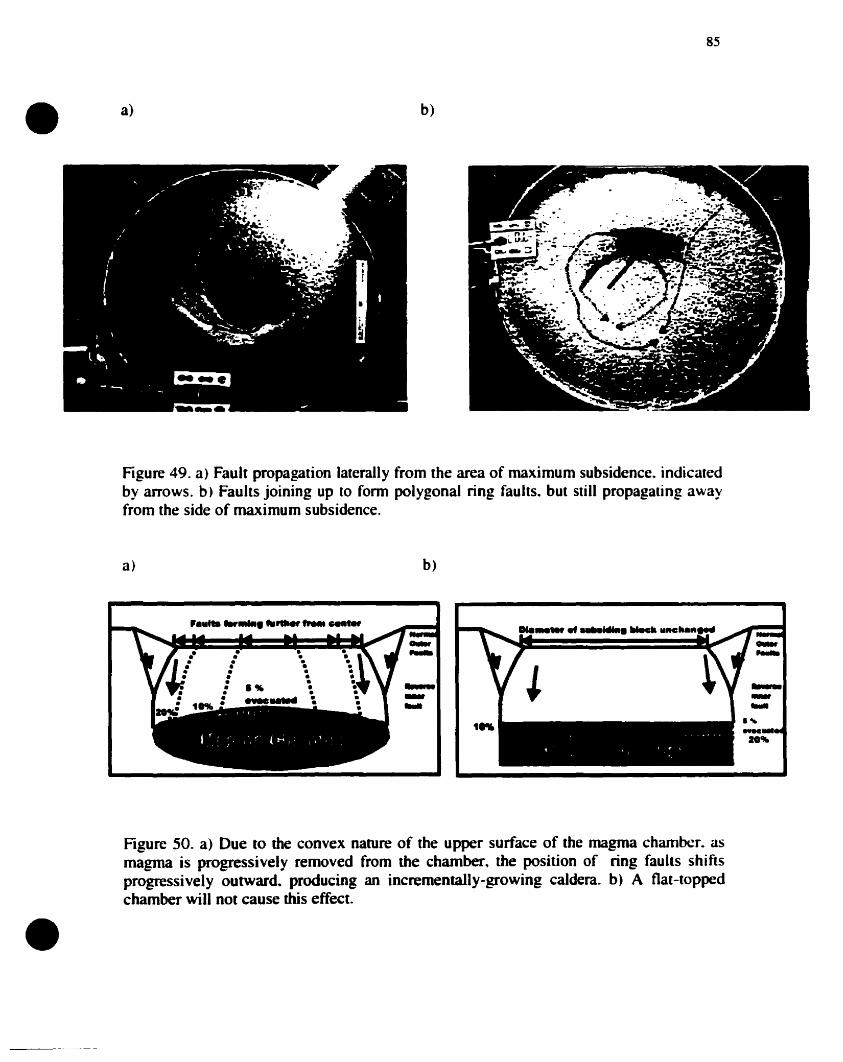
• a) b)
85
Figure 49. a) Fault propagation laterally from the area of maximum subsidence. indicaledby arrows. b) Faults joining up to fonn polygonal ring faults. but still propagaling awayfrom the side of maximum subsidence.
a) b)
........te-.
.........,_...20'"
•Figure 50. a) Due to the convex nature of the upper surface of the magma chambcr. asmagma is progressively removed from the chamber. the position of ring faults shiftsprogressively outward. producing an incrementally-growing caldera. b) A tlat-toppedchamber will not cause this effect.
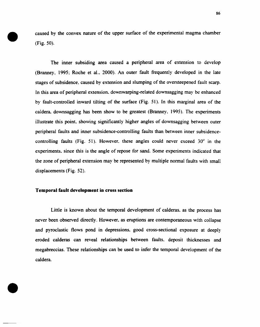
•
•
86
caused by the convex nature of the upper surface of the experimental magma chamber
(Fig. 50).
The inner subsiding area caused a peripheral area of extension to develop
(Branney, 1995~ Roche et al.. 2000). An outer fault frequently developed in the late
stages of subsidence. caused by extension and slumping of the oversteepened tàult scarp.
In this area of peripheral extension. downwarping-related downsagging may be enhanced
by fault-controlled inward tilting of the surface (Fig. 51). In this marginal area of the
caldera. downsagging has been show to be greatest (Branney. 1995). The experiments
illustrate this point. showing significantly higher angles of downsagging between outer
peripheral faults and inner subsidence-controlling faults than between inner subsidence
controlling faults (Fig. 51). However. these angles could never exceed 30° in the
experiments. since this is the angle of repose for sand. Sorne experiments indicated that
the zone of peripheral extension May be represented by multiple normal faults with small
displacements (Fig. 52).
Temporal Cault development in cross section
Little is known about the temporal development of calderas. as the process has
never been observed directly. However. as eruptions are contemporaneous with collapse
and pyroclastic flows pond in depressions. good cross-sectional exposure at deeply
eroded calderas cao reveal relationships between faults. deposit thicknesses and
megabreccias. These relationships can be used to infer the temporal development of the
caldera.
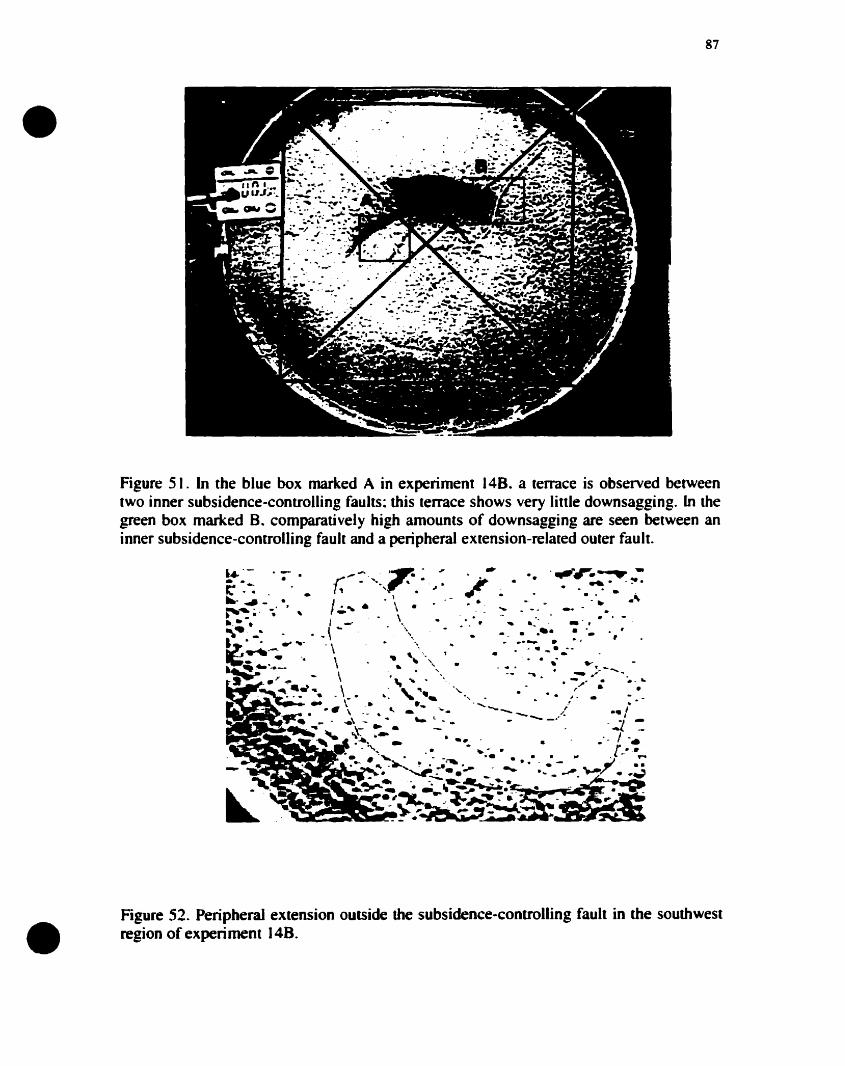
•
•
87
Figure 5 1. In the blue box marked A in experiment 148. a terrace is observed betweentwo inner subsidence-controlling faults: this terrace shows very tinle downsagging. ln thegreen box marked B. comparatively high amounts of downsagging are seen between aninner subsidence-controlling fault and a peripheral extension-related outer fault.
~:~ .':- (;--:'··,7.:~:·;· ...~~~~~~.. .1 _ ~ ., .... • ....~ --' .~ I.;.~· \. . • ..~.'. , \ ... . -. ... -•.• • i -- • '." .:. - . 1
"\. _.. . . -\ ... '\\ . .•. ..- . 'l~:""""':".-. .. 'Ir . \ - "'~••:.:'
~.... \ .. """ 1 • .... ..~ ..' .. . '\,~. ..s- ..- \ - -- .... - ./--
S .' ~ - " ... ~ • -~.. '. - ...~~~~.~ , \- ..:,"... ......., . .. / ~ .~~.. \. ._....... ' ......~',.~ ... \ ' ..... - ~. --_/. ._/
1...' ~ -' ..\"~" '- < • - -. _.' • -1 ~~ ~ ~:- ~_. . 1·
.," ....~ - ..... ·"l··, ... . .' . .......i;;,.~~ .• ..~~. . . . .......,. - ........ ~ .. ". ... -. .~ · "'-- ..
".:Iar-.~_~. "'~ -. _ .~ - ...... -- ••~... ". , ..---.. -...... ~..~.. .--là -....~.~~ - . _._..~ ~~~~~ ...."-C~~_5.~s: ;-~-----.;_ -.o!- .- .~-------
Figure 52. Peripheral extension outside the subsidence-controlling fault in the southwestregion of experiment 148.
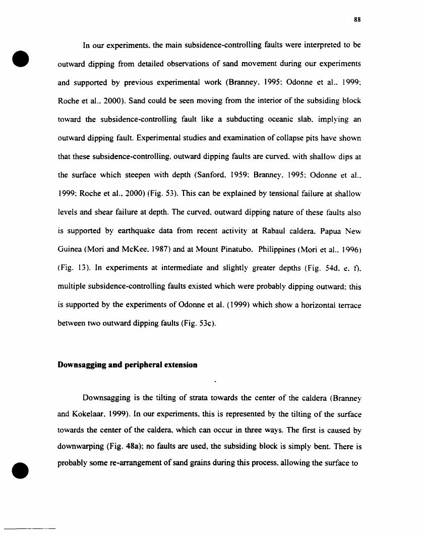
•
•
88
In our experiments. the main subsidence-controlling faults were interpreted to be
outward dipping from detailed observations of sand movement during our experiments
and supported by previous experimental work (Branney. 1995; adonne et al.. 1999:
Roche et al.. 2000). Sand could be seen moving from the interior of the subsiding block
toward the subsidence-controlling fault like a subducting oceanic slab. implying an
outward dipping fault. Experimental studies and examination of collapse pits have shown
that these subsidence-controlling, outward dipping faults are curved. with shallow dips at
the surface which steepen with depth (Sanford. 1959: Branney. 1995: adonne et al..
1999: Roche et al.. 2000) (Fig. 53). This can be explained by tensional failure at shallow
levels and shear failure at depth. The curved. outward dipping nature of these tàults also
is supported by earthquake data from recent activity at Rabaul caldera. Papua New
Guinea (Mori and McKee. 1987) and at Mount Pinatubo. Philippines (Mori et al.. 1996)
(Fig. 13). In experiments at intermediate and siightly greater depths (Fig. 54d. e. t).
multiple subsidence-controlling faults existed which were probably dipping outward: this
is supported by the experiments of adonne et al. (1999) which show a horizontal terrace
bet\veen two out\vard dipping faults (Fig. 53c).
Downsagging and peripheral extension
Downsagging is the tilting of strata towards the center of the caldera (Branney
and Kokelaar. 1999). In our experiments, this is represented by the tilting of the surface
towards the center of the caldera. which cao occur in three ways. The tirst is caused by
downwarping (Fig. 48a); no faults are used, the subsiding block is simply bent. There is
probably sorne re-arrangement of sand grains during this process, allowing the surtàce to
89
a)
•1 .1A f
c)
h)
c..............
d)
•
Figure 53. Outward dipping faults which are curved and steepen with depth. a)Experimental models (Sanford. 1959). b) Ice-melt collapse pits (Branney, 1995). c)Experimental models from Odonne et al. (1999); this diagram also shows horizontaltenaces between parallel. outward dipping faults. d) Experimental model from Roche etal. (2000); this figure also shows peripheral inward lifting (downsaggjng) between innerand outer faults.
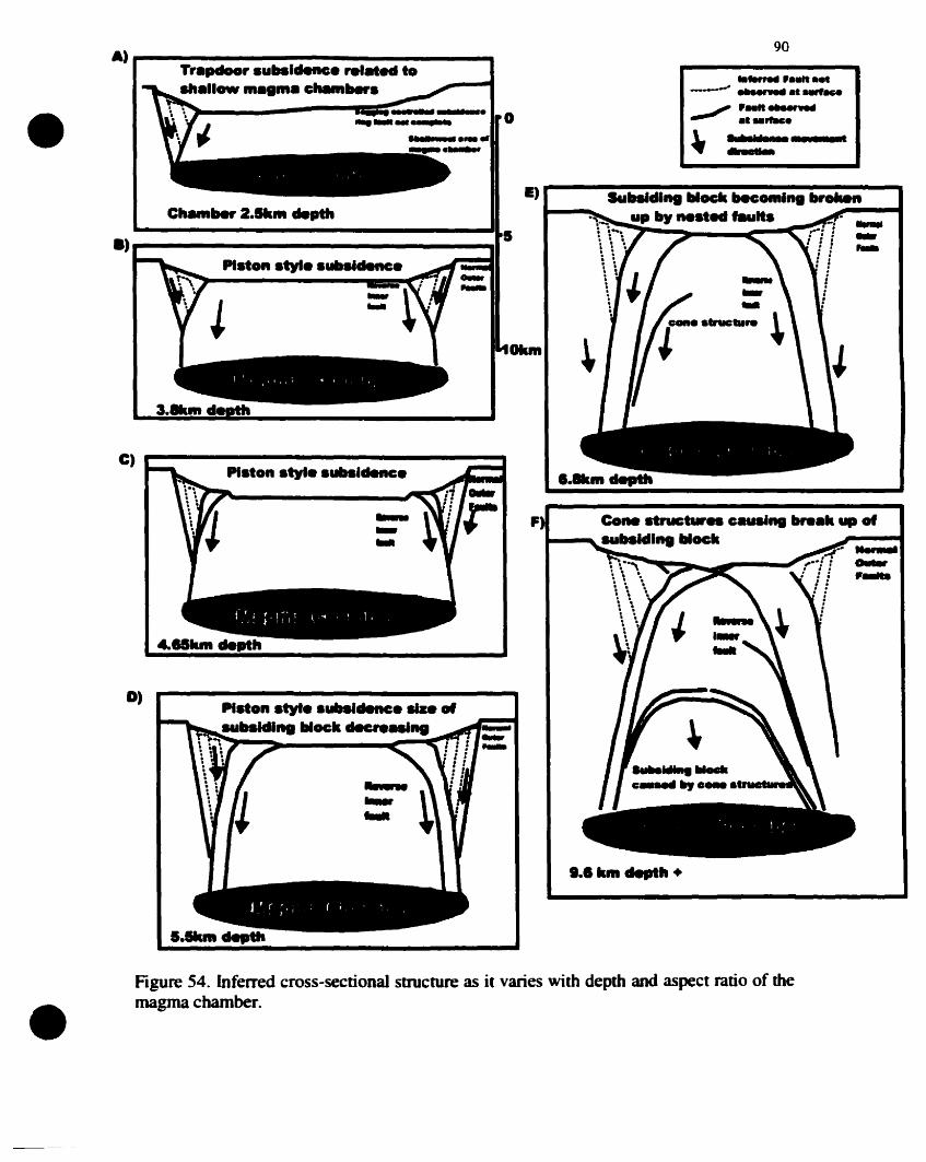
• •• k..........
Co_ .truct.... cau.'''' ......k .. of
1--,"'''''''l1li "'ockF
..............
PI.ton .tyI......denc.
PI.ton .tyI......denc of................ockdec ...
Figure 54. Inferred cross-sectional structure as it varies with depth and aspect ratio of themagma chamber.
D)
C)
A)90
Tr.pdoor .ubsldenc. re...... to ....,. ..............ow ......... c............ --- ...",...t..r••
• 0,.".,/ .MII .......
et ......
~....~._•• III li.._....
E) SU....dl.. lIIock McOlll'" br.....C......... 2..... de"'" uplly ....ed ..u... .....
a) 5 -...Piston • .,.......cIenc.
•
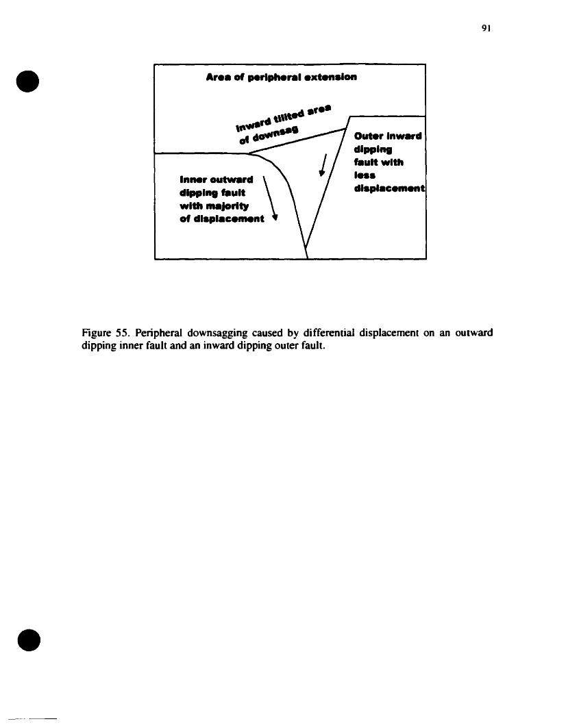
91
Ar•• of .........,.1 .xt....lon• ...,..r. \,\"\,,--_ .ot -
Inner outward \dlppl taultwlth jorl.,of dl.pl.c....nt
Out.r In••rddlppl...tault .Ith
••••dl.pl.c....ent
•
Figure 55. Peripheral downsagging caused by differential displacement on an outwarddipping inner fault and an inward dipping outer fault.
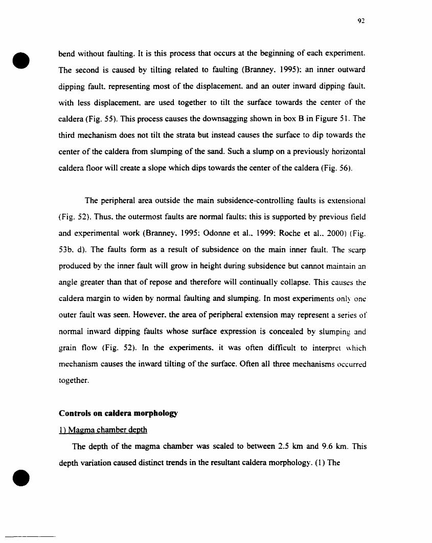
•
•
92
bend without faulting. It is this process that occurs at the beginning of each experiment.
The second is caused by tilting related to faulting (Branney. 1995): an inner outward
dipping fault. representing most of the displacement. and an outer inward dipping fauft.
with less displacement. are used together to tilt the surface towards the center of the
caldera (Fig. 55). This process causes the downsagging shown in box B in Figure 51. The
third mechanism does not tilt the strata but instead causes the surface to dip towards the
center of the caldera from slumping of the sand. Such a slump on a previously horizontal
caldera tloor will create a slope which dips towards the center of the caldera (Fig. 56).
The peripheral area outside the main subsidence-controlling tàults is extensional
(Fig. 52). Thus. the outermost faults are normal faults: this is supponed by previous field
and experimental work (Branney. 1995: Odonne et aL. 1999: Roche et aL. 2000) (Fig.
53b. d). The faults form as a result of subsidence on the main inner fault. The scarp
produced by the inner fault will grow in height during subsidence but cannot maintain an
angle greater than that of repose and therefore will continually collapse. This causes the
caldera margin to widen by normal faulting and slumping. In most experiments only one
outer fault was seen. However. the area of peripheral extension may represent a series of
normal inward dipping faults whose surface expression is concealed by slumping and
grain flow (Fig. 52). In the experiments. it was often difficult to interpret whîch
mechanism causes the inward ùlting of the surface. Often all three mechanisms occurred
together.
Controls on caldera morpbology
1) Magma chamber depth
The depth of the magma chamber was scaled to between 2.5 km and 9.6 km. This
depth variation caused distinct trends in the resultant caldera morphology_(1) The
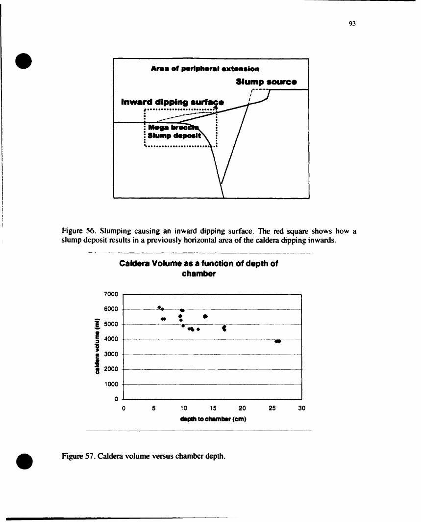
•93
A.... of ...,Iph.,•• extension
Siump source
Inw.~~.~~~~~.~~~~e· ....-......--· ~. :· ~~ :.:
: Siump c1eposlt :· .· .~ •.•.............••.••..••
Figure 56. Slumping causing an inward dipping surface. The red square shows how aslump deposit results in a previously horizontal area of the caldera dipping inwards.
._----------------"------._-"-
Caldera Volume as a function of depth ofchamber
7000
6000
Î 5000-14000
1I! 3000
:1Il 2000
1000
..- ..• • ••.... C
._---
.f----
------~-
oo 5 10 15 20
.pIh to c"'mbe, (cm)
25 30
• Figure 57. Caldera volume versus chamber depth.
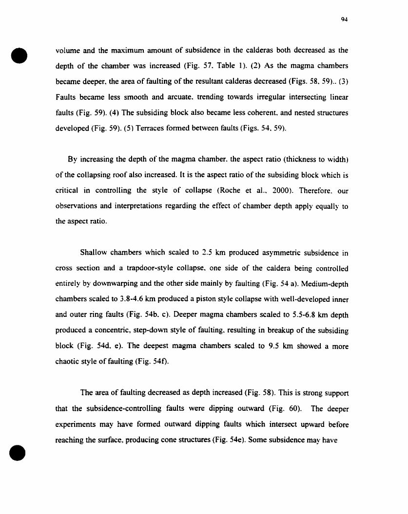
•
•
94
volume and the maximum amount of subsidence in the calderas both decreased as the
depth of the chamber was increased (Fig. 57, Table 1). (2) As the magma chambers
became deeper, the area of faulting of the resultant calderas decreased (Figs. 58, 59).. (3)
Faults became less smooth and arcuate, trending towards irregular intersecting linear
faults (Fig. 59). (4) The subsiding block also became less coherent.. and nested structures
developed (Fig. 59). (5) Terraces formed between faults (Figs. 54. 59).
By increasing the depth of the magma chamber. the aspect ratio (thickness to width)
of the collapsing roof also increased. Il is the aspect ratio of the subsiding block which is
critical in controlling the style of collapse (Roche et al.. 2000). Therefore. our
observations and interpretations regarding the effect of chamber depth apply equally to
the aspect ratio.
Shal10w chambers which scaled to 2.5 km produced asymmetric subsidence in
cross section and a trapdoor-style collapse. one side of the caldera being controlled
entirely by dO\Vfiwarping and the other side mainly by faulting (Fig. 54 a). Medium-depth
chambers scaled to 3.8-4.6 km produced a piston style collapse with well-developed inner
and outer ring faults (Fig. 54b. c). Deeper magma chambers scaled to 5.5-6.8 km depth
produced a concentric~ step-down style of faulting. resulting in breakup of the subsiding
block (Fig. 54d. e). The deepest magma chambers scaled to 9.5 km showed a more
chaotic style of faulting (Fig. 540.
The area of faulting decreased as depth increased (Fig. 58). This is strong suppon
that the subsidence-controlling faults were dipping outward (Fig. 60). The deeper
experiments may have formed outward dipping faults which intersect upward before
reaching the surface.. producing cone structures (Fig. 54e). Sorne subsidence May have
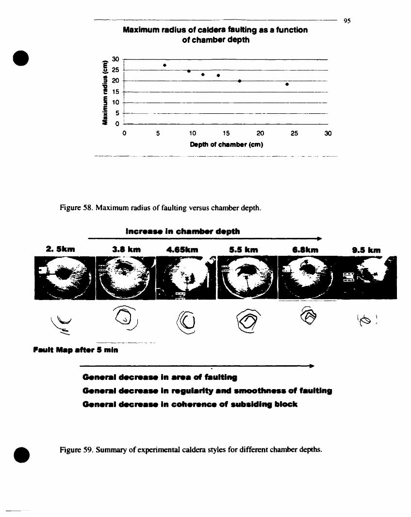
95
Maximum radius of caldera taulting as a functionof chamber depth
302510 15 20
Depth of chllmber (cm)
5
_ 30 -rI--------------------
! 25 +-1----·--....--------------~
. ..; 20 ------------4•.......--------•1151---------~-
J1°5 1Il +-1----:E 0 ---1 _
o
•
Figure 58. Maximum radius of faulting versus chamber depth.
•2.lkm 3.1 km 4••Skm S•• km ••Ikm B.5km
F...lt "p .fter 5 min
Gene 1cIec..... In .re. of fIIultl...
Gene 1clecre•• In regul.rlty .nd .moo"'n••• of f.ultln.
G.n 1decre•• In coh.rence of .ubaldllII black
• Figure 59. Summary of experimental caldera styles for different chamber depths.
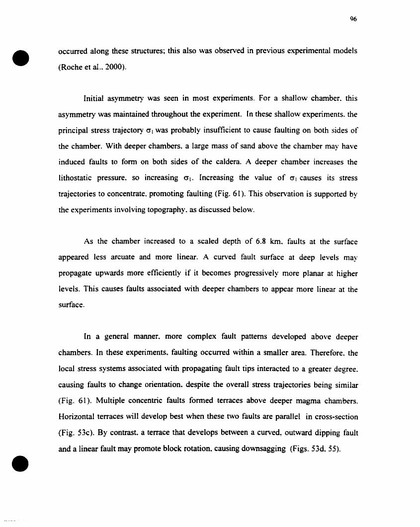
•
•
96
occurred along these structures; this also was observed in previous experimental models
(Roche et al.~ 2000).
Initial asymmetry was seen in most experiments. For a shallo\v chamber. this
asymmetry was maintained throughout the experiment. In these shallow experiments. the
principal stress trajectory 0'1 was probably insufficient to cause faulting on bath sides of
the chamber. With deeper chambers. a large mass of sand above the chamber may have
induced faults to form on both sides of the caldera. A deeper chamber increases the
lithostatic pressure. so increasing (.TI. Increasing the value of 0'1 causes its stress
trajectories to concentrate. promoting faulting (Fig. 61). This observation is supported by
the experiments involving topography~ as discussed below.
As the chamber increased to a scaled depth of 6.8 km. faults at the surface
appeared less arcuate and more linear. A curved fault surface at deep levels may
propagate upwards more efficiently if it becomes progressively more planar at higher
levels. This causes faults associated with deeper chambers to appear more linear at the
surface.
[n a general manner. more complex fault patterns developed ahove deeper
chambers. In these experiments. faulting occurred within a smaller area. Therefore. the
local stress systems associated with propagating fault tips interacted ta a greater degree.
causing faults ta change orientation. despite the overall stress trajectories being similar
(Fig. 61). Multiple concentric faults formed terraces above deeper magma chambers.
Horizontal terraces will develop best when these two faults are parallel in cross-section
(Fig. 53c). By contrast. a terrace that develops between a curved, outward dipping fault
and a linear fault may promote block rotation, causing downsagging (Figs. 53d. 55).
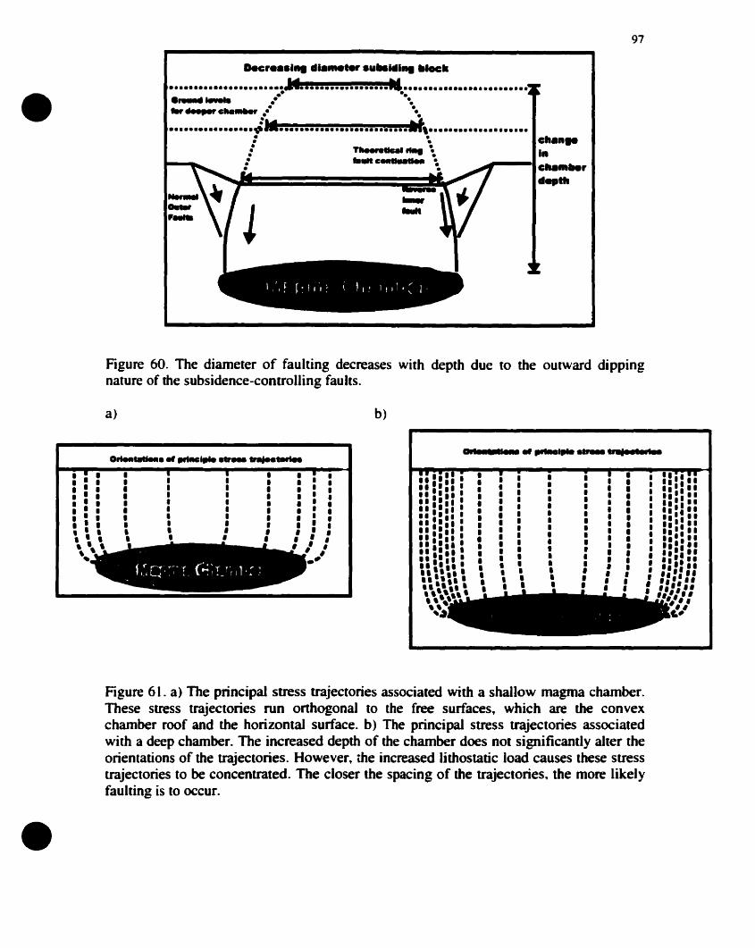
97
cll.n..ln
~---Ic"'."'rd...'"
•••••••••••••••••••••••~•••••••.••••••••••-.L•••••••••••••••••••••••.•• •.~...... ..- -',_~c....-r ,,- '.,•••••••••••••••••~I t, .
• •- .! TIII••,.tI....... \: ..."~ ~. .
Decr••a.1II d......_ a.IIa"'.1II IIIocli
•
Figure 60. The diameter of faulting decreases with depth due to the outward dippingnature of the subsidence-controlling faults.
........ ,,_ ...................,.......::': Il,,', Il.. '.....', Il•• '. Il,,'....,', Il.,'. Il' .....••••• Il" • Il,.:. Il•••• Ill, ,II,':. Il
"" """ "'#. ,
i#'
•,1
11•
, :'.: 1, , ", ':.,, .", ,'"·,',.·,'", ,,',', ,,, :'..-• , l'Il .:,.• ••••Il l'"~I'I •Il,1 ,II,. ,' •• 1
" "',~
b)
, ., ', ', ., ', '.:: ., ., l."
1,••,••1••
••,•11•,•
,,,,1,,,•
,,,,,•,,1•
a)
l , •, , .·.', .'·, .·, ': .:, ' ,• 1 1, l ,, '-
•
Figure 61. a) The principal stress trajectories associated with a shallow magma chamber.These stress trajectories run onhogonal to the free surfaces, which are the convexchamber roof and the horizontal surface. b) The principal stress trajectories associatedwith a deep chamber. The increased depth of the chamber does not significantly alter theorientations of the trajectories. However, the increased lithostatic load causes these stresstrajectories to he concentrated. The closer the spacing of the trajectories, the more likelyfaulting is to occur.
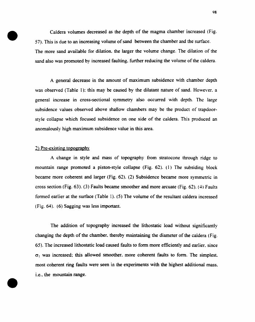
•
•
98
Caldera volumes decreased as the depth of the magma chamber increased (Fig.
57). This is due to an increasing volume ofsand between the chamber and the surtàce.
The more sand available for dilation. the larger the volume change. The dilation of the
sand also was promoted by increased faulting. funher reducing the volume of the caldera.
A general decrease in the amount of maximum subsidence with chamber depth
was observed (Table 1): this May be caused by the dilatant nature of sand. However. a
general increase in cross-sectional symmetry also occurred with depth. The large
subsidence values observed above shallow chambers May be the product of trapdoor
style collapse which focused subsidence on one side of the caldera. This produced an
anomalously high maximum subsidence value in this area.
1) Pre-existing topographv
A change in style and mass of topography from stratocone through ridge to
mountain range promoted a piston-style collapse (Fig. 62). (1) The subsiding block
became more coherent and larger (Fig. 62). (2) Subsidence becarne more symmetric in
cross section (Fig. 63). (3) Faults became smoother and more arcuate (Fig. 62). (4) Faults
formed earlier al the surface (Table 1). (5) The volume of the resultant caldera increased
(Fig. 64). (6) Sagging was less important.
The addition of topography increased the lithostalic load without significantly
changing the depth of the chamber. thereby maintaining the diameter of the caldera (Fig.
65). The increased lithostatic load caused faults to form more efficiently and earlier. since
crl was increased; tbis allowed smoother. more coherent faults to fonn. The simplest.
most coherent ring faults were seen in the experiments with the highest additional mass.
i.e., the mountain range.
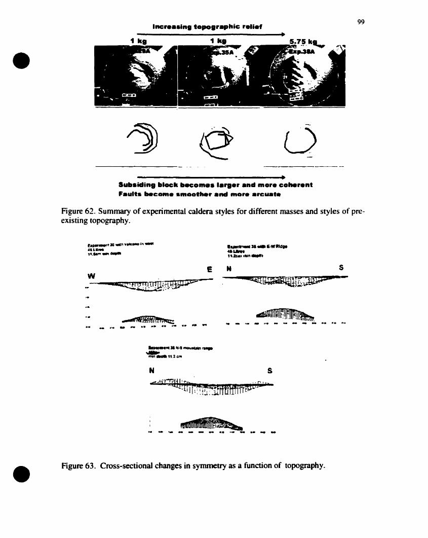
•99
oSult.icling IIlock Itecom•• I.,..r and more coherentF.ults "'co",. smoather and more .rcu.t.
Figure 62. Summary of experimental caldera styles for different masses and styles of preexisting topography.
,.......'311 ....' ....._1" ..."IL."1•...", .........
• ...~...E-WIttd...........U~.I ..." .....
w E
-... 1'"
_
.• '1... ~.. ... .. ... .. .... .. ". .. ~~I~"IIIII'IH:~nJII~tU~..... ,.• _.,.-~.-_ ...
lIInI.eIIt. Nol.,..",......, ,...
.~"'.11.: I:"t
N s
•~......... - - ..
Figure 63. Cross-sectional changes in symmetry as a function of topography.
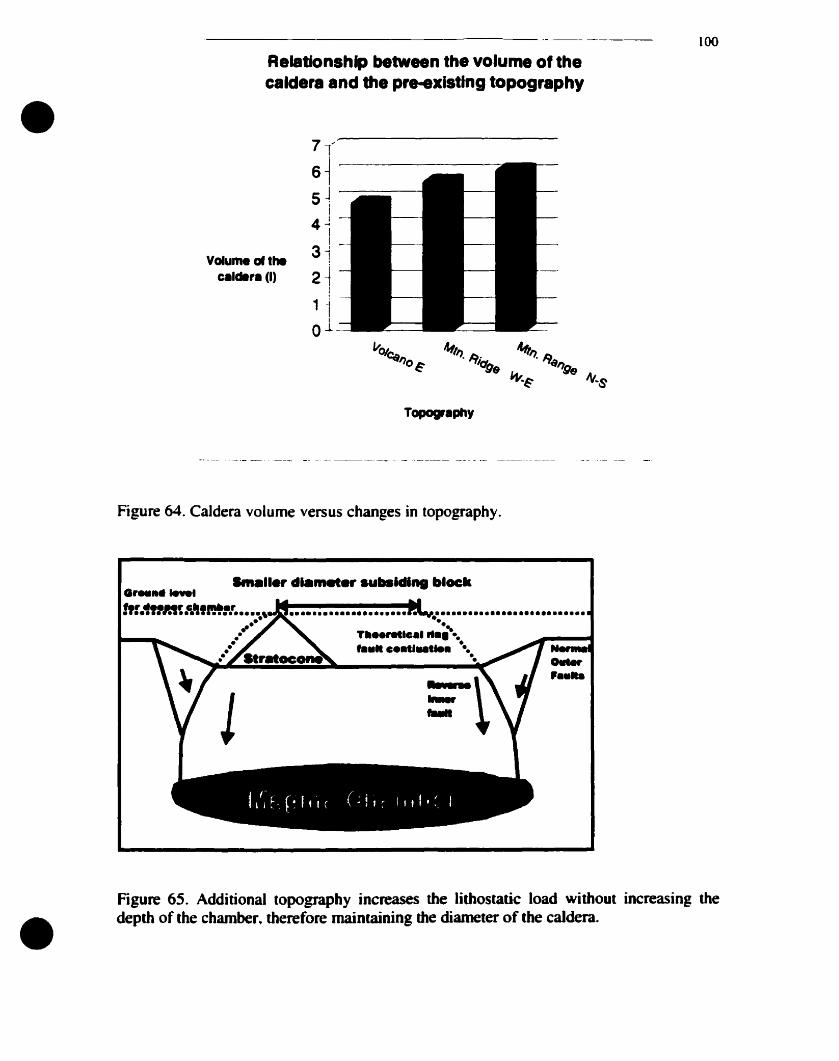
•100
Ael8tionshlp between the volume of theealdera and the pre-exlstlng topography
Volume of theealœ,a (1)
Topogrephy
Figure 64. Caldera volume versus changes in topography.
......,....
• r.......1
........•...••.•...... ...................•...•...-.T....retlC.IIt.~ ..... c••tl_t ...
•Figure 65. Additional topography increases the lithostatic load without increasing thedepth of the chamber. therefore maintaining the diameter of the caldera.
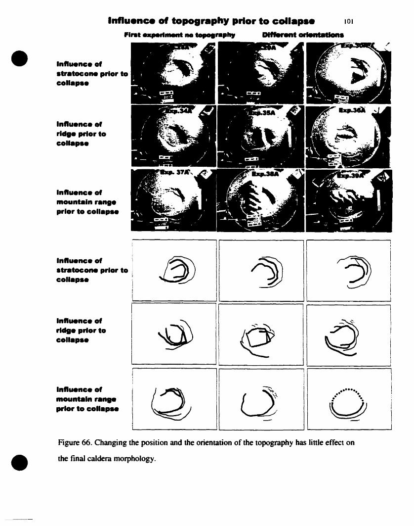
•Influence of topography prlor to collap.e 101
FI.........rI....... ne .........pllr DI......t orientations
Influenc. of.....tocon. prlor lacollap••
Influenc. ofrld•• prlor lacollap••
Influenc. ofmounlaln ran••prlor la collap..
Figure 66. Changing the position and the orientation of the topography has tinle effect on
the final caldera morphology.•
Influenc. of.....tocone prlor lacollap••
Influenc. ofri.... prlorlocollap••
Influenc. ofmountaln raft8e....Ior to coll.p..
1
11
1
1
@ ~ ~1
i 111
1
1 1
1
1
1
1
1 ~ e Q 1
1
1
,11
Il Il .
L---Q_IL..---LJ_~\----J "----0_~··_____..J
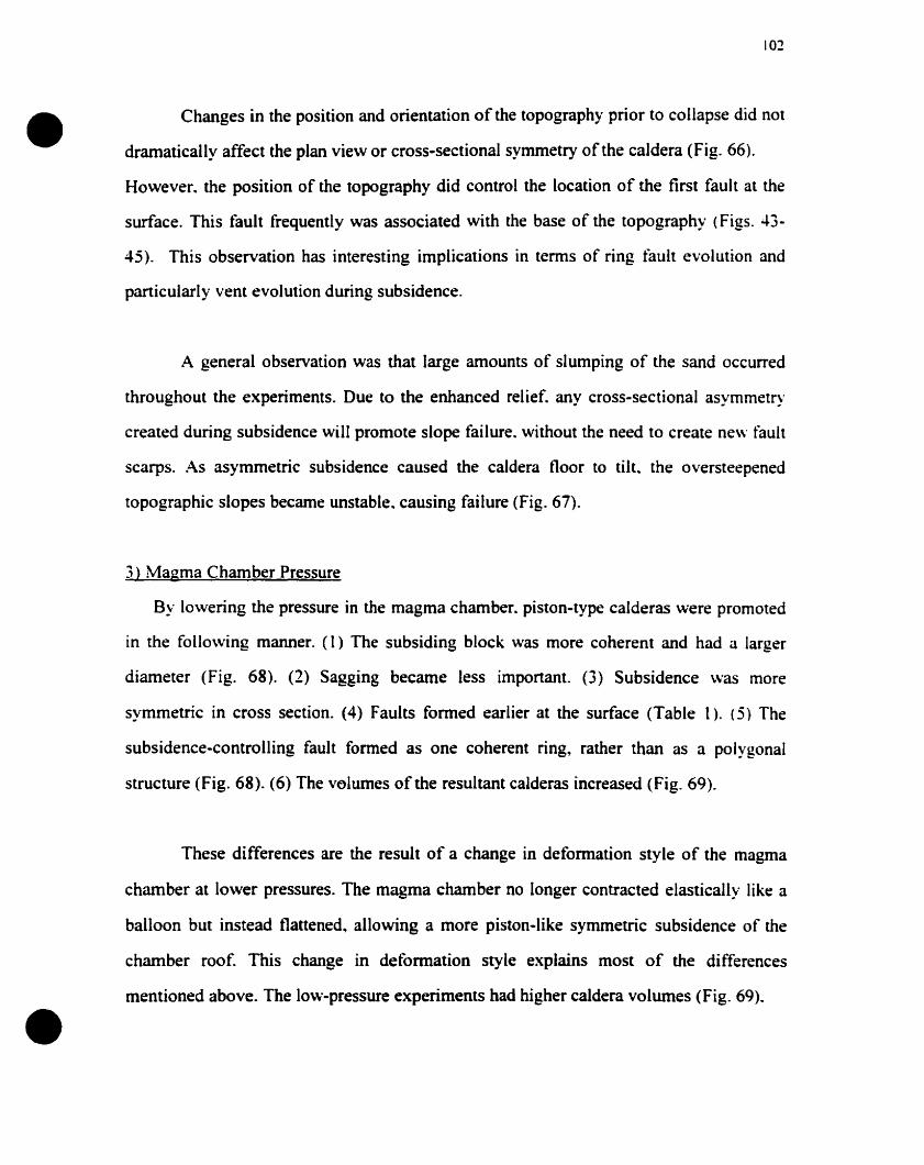
•
•
102
Changes in the position and orientation of the topography prior to collapse did not
dramatically affect the plan vie\v or cross-sectional symmetry of the caldera (Fig. 66).
However. the position of the topography did control the location of the first fault at the
surface. This fault frequently was associated with the base of the topography (Figs. 43·
45). This observation has interesting implications in terms of ring fault evolution and
particularly vent evolution during subsidence.
A general observation was that large amounts of slumping of the sand occurred
throughout the experiments. Due to the enhanced relief. any cross-sectional asymmetry
created during subsidence will promote slope faHure. without the need to create new fault
scarps. As asymmetric subsidence caused the caldera floor to tilt. the oversteepened
topographie slopes became unstable.. causing failure (Fig. 67).
3) Magma Chamber Pressure
By lo\vering the pressure in the magma chamber. piston-type calderas were promoted
in the follo\ving manner. (1) The subsiding block was more coherent and had a larger
diameter (Fig. 68). (2) Sagging became less important. (3) Subsidence was more
symmetric in cross section. (4) Faults formed earlier at the surface (Table 1). (5) The
subsidence·controlling fault formed as one coherent ring, rather than as a polygonal
structure (Fig. 68). (6) The volumes of the resultant calderas increased (Fig. 69).
These differences are the result of a change in deformation style of the magma
chamber at lower pressures. The magma chamber no longer contracted elastically like a
balloon but instead flattened.. allowing a more piston-like symmetric subsidence of the
chamber roof. This change in deformation style explains most of the differences
mentioned above. The lo\\··pressure experiments had higher caldera volumes (Fig. 69).
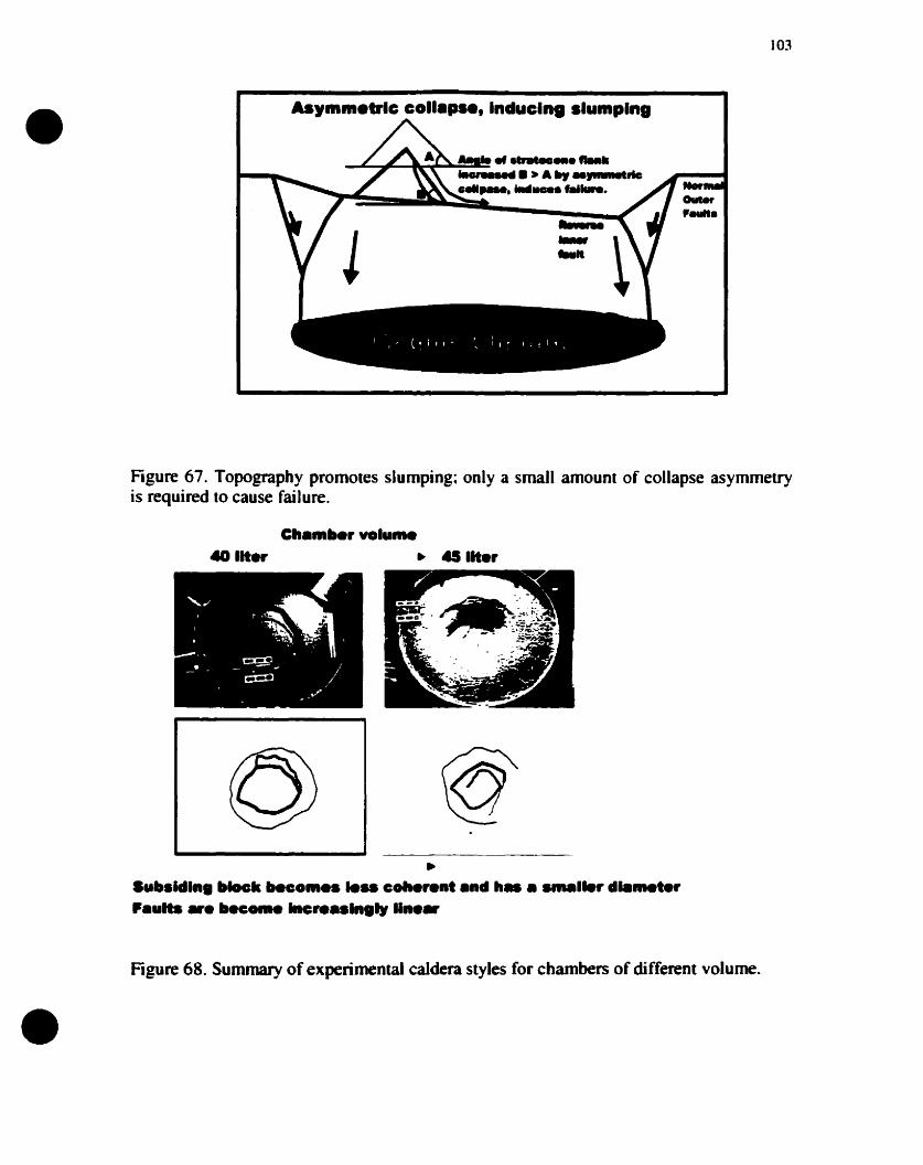
•103
As'.IIn.trlc coll.pH, Induclnl .Iumplnl
Figure 67. Topography promotes slumping; only a small amount of collapse asymmetryis required (0 cause failure.
40 lit... • a liter
•
•Sub.ldlnl "Iocll beco........ coll.rent end Il..........r d.....t.rPeulb ._ bec..... Incre••lngly lin••
Figure 68. Summary of experimental caldera styles for chambers of different volume.
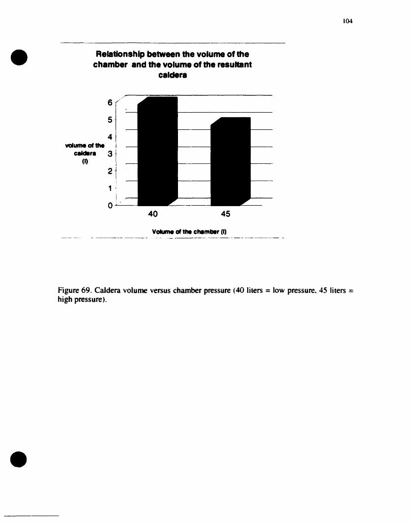
•104
Relatlonshlp between the volume of thechamber and the volume of the resuttant
caldera
6
5
4volume of the 1
calder. 31(1)
211 1
o -40 45
•
Figure 69. CaJdera volume versus chamber pressure (40 Hiers = low pressure. 45 Hters =high pressure).
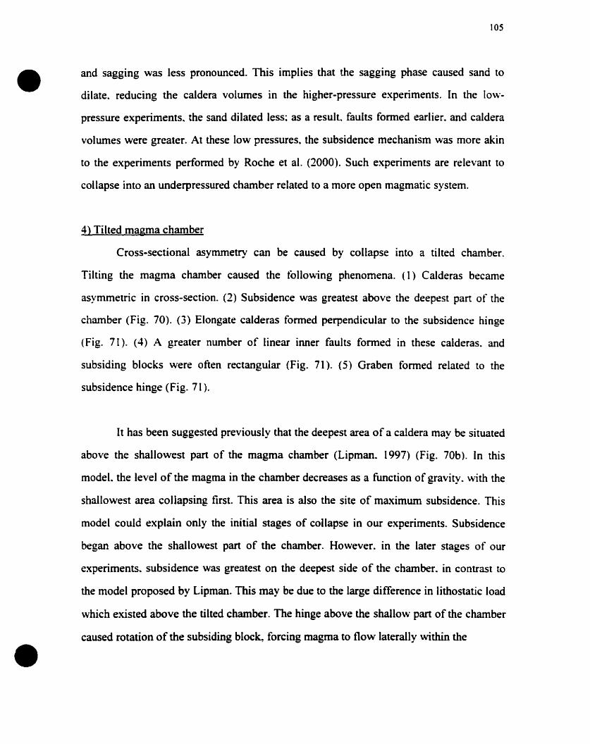
•
•
105
and sagging was less pronounced. This implies that the sagging phase caused sand to
dilate. reducing the caldera volumes in the higher-pressure experiments. In the low
pressure experiments~ the sand dilated less: as a result. faults formed earlier. and caldera
volumes were greater. At these low pressures. the subsidence mechanism was more akin
to the experiments performed by Roche et al. (2000). Such experiments are relevant to
collapse into an underpressured chamber related to a more open magmatic system.
4) Tilted magma chamber
Cross-sectional asymmetry cao be caused by collapse into a tilted chamber.
Tilting the magma chamber caused the following phenomena. (1) Calderas became
asymmetric in cross-section. (2) Subsidence was greatest above the deepest part of the
chamber (Fig. 70). (3) Elongate calderas formed perpendicular to the subsidence hinge
(Fig. 71). (4) A greater number of linear inner faults formed in these calderas. and
subsiding blocks were often rectangular (Fig. 71). (5) Graben formed related to the
subsidence hinge (Fig. 71).
It has been suggested previously that the deepest area of a caldera may be situated
above the shallowest part of the magma chamber (Lipman. 1997) (Fig. 70b). [n this
modeL the level of the magma in the chamber decreases as a function of gravity. with the
shallowest area collapsing first. This area is also the site of maximum subsidence. This
model could explain only the initial stages of collapse in our experiments. Subsidence
began above the shallowest part of the chamber. However. in the later stages of our
experiments~ subsidence was greatest on the deepest side of the chamber. in contrast to
the mode[ proposed by Lipman. This may be due to the large difference in lithostatic load
which existed above the tilted chamber. The hinge above the shallow part of the chamber
caused rotation of the subsiding bloc~ forcing magma to flow laterally within the
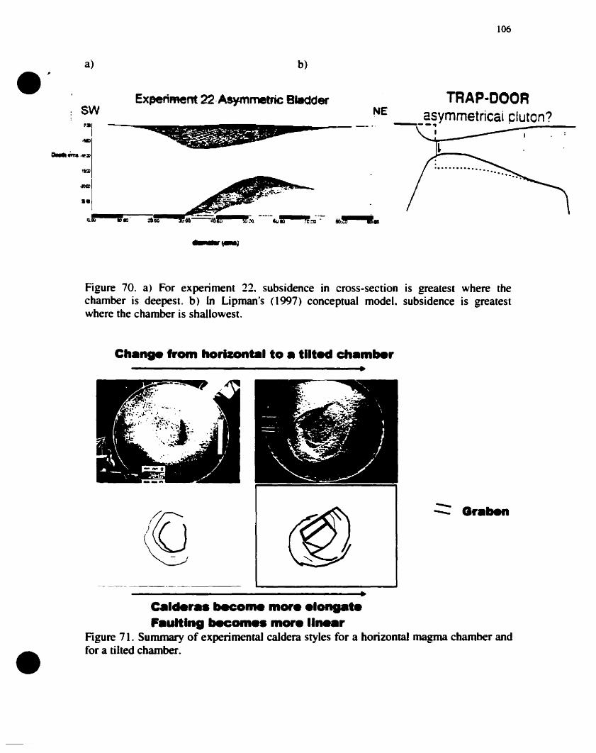
106
b)
Experiment 22·AsymmebicBledder TRAP-OOORNE asymmetricai clutcn?--------_ .. ---, ~'-----~~ ~I_~
a).;SW~:al
1...a.-. .......~
Il'll
..,=ae
IllK1 IDm
Figure 70. a) For experiment 22. subsidence in cross-section is greatest where thechamber is deepesl. b) ln Lipmants (1997) conceptual model. subsidence is greateslwhere the chamber is shallowest.
Ch.... 'rom horlzonbll to • tllted ch.mlle,
•
•C.lder•• become more .I t.F.ultlRg becCHII•• more Il '
Figure 71. Summary of experimental caldera styles for a horizontal magma chamber andfor a tilted chamber.
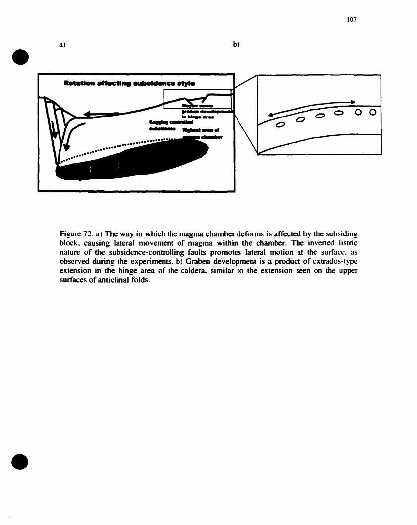
•a)
......... -"ectl nce atyle
b)
107
o 0 0 0
•
Figure 72. a) The way in which the magma chamber deforms is affected by the subsidingblock. causing laIerai movement of magma within the chamber. The invened listricnature of the subsidence-controlling faults promotes lateral motion at the surface. asobserved during the experiments. b) Graben development is a product of extrados-typeextension in the hinge area of the caldera. similar to the extension seen on the uppersurfaces of anticlinal folds .
•
•
108
chamber (Fig. 72). Graben development in the hïnge area was related to extrados-type
extension caused by bending of the crust (Fig. 7'1).
Discussion
The nature and origin of caldera faults
Caldera faults are frequently thought of as simple ring structures which are
vertical or inward dipping (Smith and Bailey. 1968: Lipman. 1984). More recent studies
have shown that this ring structure also may be outward dipping (Mori and McKee. 1987:
Ekstrom. 1994: Branney. 1995: Roche et aL 2000). Many models also have been
proposed for subsidence unrelated to ring faults (Walker. 1984~ Lipman. 1997; 2000). In
this section we demonstrate that simple piston-like ring faults rarely develop. and that the
subsidence-controlling faults form in a number of ways and orientations for different
reasons. The term ··ring fault'· may therefore not he suitable for many subsidence
controlling faults at calderas.
Homogeneous experimenta! conditions generally promote subsidence of a
coherent block. Under such conditions. circular ring faults have been produced (Roche et
al.. 2000). However. the results from our experiments show that circular ring faults rarely
form; the ring fau!t is frequently polygonal and constructed from connecting tinear or
sub-arcuate faults (Figs. 38-40). Such structures commonly are seen at eroded ring
complexes associated with calderas, such as the Ossipee cauldron. New Hampshire.
U.S.A. the Sande cauldron. Oslo region, Norway'O the Liruei ring complex'O Nigeria. and
the Ishizuchi cauldron.. southwestem Japan (Fig. 73). In these polygonal structures.
corners form where faults joïn. Where faults join. one fault may extend outside the ring
structure (Fig. 40)~ alternatively, faults may be seen to cross (Fig. 74). These corners are
preferred eruption conduits, as they represent fracture intersections and concentrations.
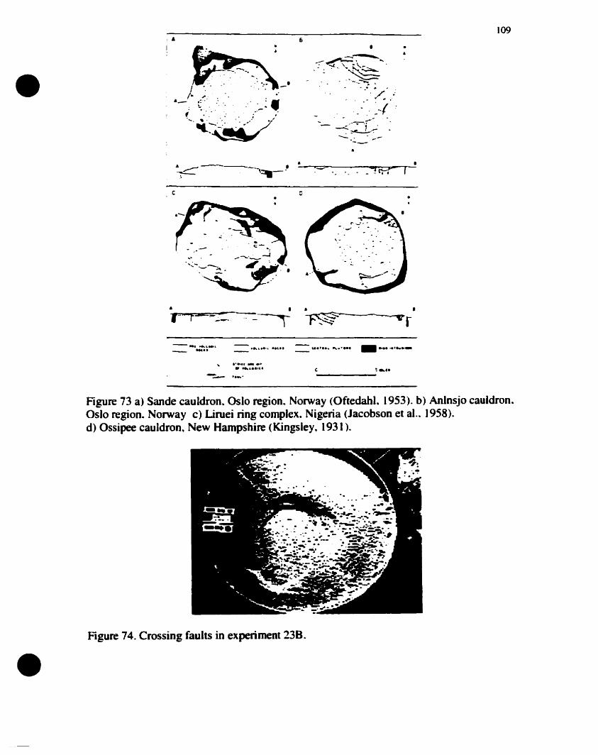
,.-
•.&
109
'-~-~ --- .
c
•--,- • •~r
--•• t ... " ,.
".'.... ~...... _ ...... f ...._
: •..-----
•
Figure 73 a) Sande cauIdron. Oslo region. Norway (Oftedahl. 1953). b) Anlnsjo cauldron.Oslo region. Norway c) Liruei ring complexe Nigeria (Jacobson et al.. 1958).d) Ossipee cauldron, New Hampshire (Kingsley, 1931).
Figure 74. Crossing faults in experiment 238.
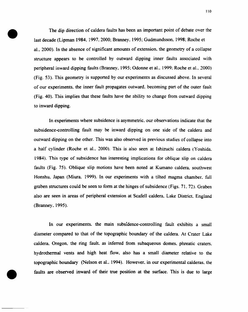
•110
The dip direction of caldera faults has been an important point of debate over the
last decade (Lipman 1984. 1997.2000; Branney. 1995; Gudmundsson. 1998; Roche et
al., 2000). In the absence of significant amounts of extension, the geometry of a collapse
structure appears to be controlled by outward dipping inner faults associated with
peripheral inward dipping faults (Branney, 1995; ûdonne et al.. 1999: Roche et al.. 1000)
(Fig. 53). This geometry is supported by our experiments as discussed above. In several
of our experiments. the inner fault propagates outward. becoming part of the outer tàult
(Fig. 40). This implies that these faults have the ability to change from outward dipping
to inward dipping.
In experiments where subsidence is asymmetric. our observations indicate that the
subsidence-controlling fault may be inward dipping on one side of the caldera and
outward dipping on the other. This was also observed in previous studies of collapse into
a half cylinder (Roche et al.. 2000). This is also seen at Ishizuchi caldera <Yoshida.
1984). This type of subsidence has interesting implications for oblique slip on caldera
faults (Fig. 75). Oblique slip motions have been noted at Kumano caldera.. southwest
Honshu. Japan (Miura.. 1999). In our experiments with a tilted magma chamber. full
graben structures could be seen to fonn at the hinges of subsidence (Figs. 71. 72). Graben
also are seen in areas of peripheral extension at Scafell caldera. Lake District. England
(Branney. (995).
In our experiments. the main subsidence-controlling fault exhibits a small
diameter compared to that of the topographie boundary of the caldera. At Crater Lake
caldera, Oregon. the ring fault. as inferred from subaqueous domes. phreatic craters.
hydrothennal vents and high heat flow. also has a small diameter relative to the
topographie boundary (Nelson et aL 1994). However. in our experimental calderas. the
• faults are observed inward of their true position al the surface. This is due to large
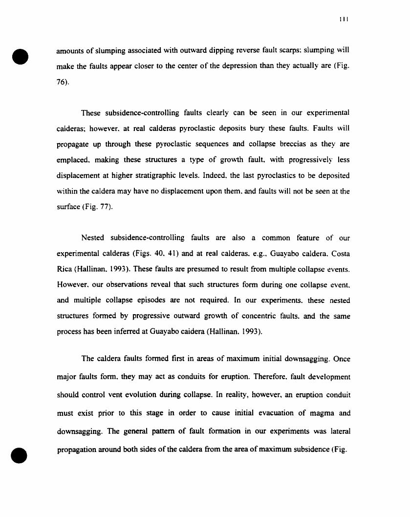
•
•
III
amounts of slumping associated with outward dipping reverse fault scarps: slumping will
make the faults appear closer to the center of the depression than they actually are (Fig.
76).
These subsidence·controlling faults clearly can be seen in our experimental
calderas; however. at real calderas pyroclastic deposits bury these faults. Faults will
propagate up through these pyroclastic sequences and collapse breccias as they are
emplaced. making these structures a type of growth fault. with progressively less
displacement at higher stratigraphie levels. Indeed. the last pyroclastics to be deposited
within the caldera may have no displacement upon them. and faults will not be seen at the
surface (Fig. 77).
Nested subsidence·controlling tàults are also a common feature of our
experimental calderas (Figs. 40. 41) and at real calderas. e.g.. Guayabo caldera. Costa
Rica (Hallinan. 1993). These faults are presumed to result from multiple collapse events.
However. our observations reveal that such structures fonn during one collapse event.
and multiple collapse episodes are not required. In our experiments. these nested
structures formed by progressive outward growth of concentric faults. and the same
process has been inferred at Guayabo caidera (Hallinan. 1993).
The caldera faults formed tirst in areas of maximum initial downsagging. Once
major faults fonn. they may act as conduits for eruption. Therefore. fault development
should control vent evolution during collapse. In reality, however. an eruption conduit
must exist prior to this stage in order to cause initial evacuation of magma and
downsagging. The general pattern of fault formation in our experiments was laterai
propagation around both sides of the caldera from the area of maximum subsidence (Fig.
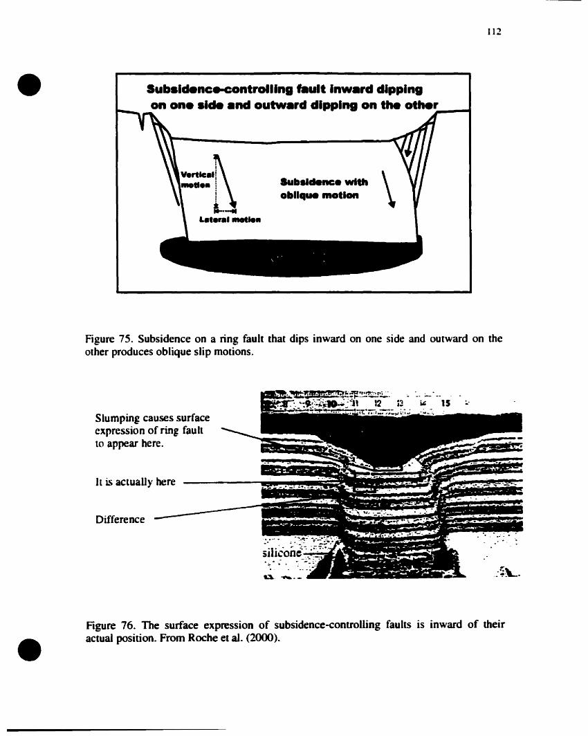
112
\Subsidence wltholtll..ue motion
V.rtlc.I~:........ i
i!W
L•••ql ........
Subs.cIence-controlllng flault Inw.rd dipplngon on. s.cIe .nd outw.rd dlpplng on the oth.r~--.•
Figure 75. Subsidence on a ring fault that dips inward on one side and outward on theother produces oblique slip motions.
Slumpinl causes surfaceexpression of ring fault(0 appear here.
Il is actually here
Difference
~. ,...-
.- ..-.
.~\....-. ..... .
•Figure 76. The surface expression of subsidence-controlling faults is inward of theiractual position. From Roche et al. (2000).
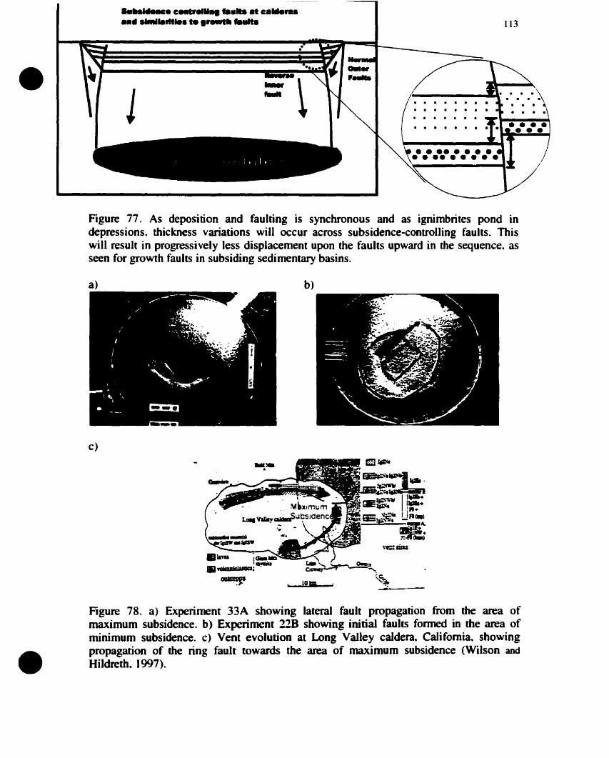
..
•......... cHtnlIl.. ta... al c....,................... te lro-tll tallits 113
Figure 77. As deposition and faulting is synchronous and as ignirnbrites pond indepressions. thickness variations will occur across subsidence-controlling faults. Thiswill result in progressively less displacement upon the faults upward in the sequence. asseen for growth faults in subsiding sedimentary basins.
a)
c)
h)
•Figure 78. a) Experiment 33A showing laIerai fault propagation from the area ofmaximum subsidence. b) Experiment 228 showing initial faults formed in the area ofminimum subsidence. c) Vent evolution at Long Valley caldera. Califomia. showingpropagation of the ring fault towards the area of maximum subsidence (Wilson and
Hildreth. 1997).
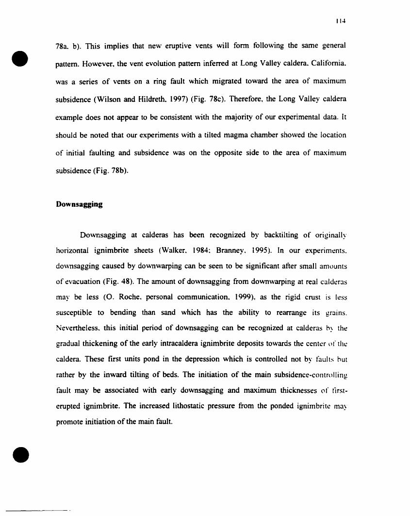
•
•
114
78a. b). This implies that new eruptive vents will form following the same general
pattern. However.. the vent evolution pattern inferred at Long Valley caldera. California.
was a series of vents on a ring fault which migrated toward the area of maximum
subsidence (Wilson and Hildreth. 1997) (Fig. 78c). Therefore.. the Long Valley caldera
example does not appear to be consistent with the majority of our experimental data. It
should be noted that our experiments with a tilted magma chamber showed the location
of initial fauiting and subsidence was on the opposite side to the area of maximum
subsidence (Fig. 78b).
Downsagging
Downsagging at calderas has been recognized by backtilting of originally
horizontal ignimbrite sheets (Walker. 1984: Branney. 1995). In our experiments.
downsagging caused by downwarping can be seen to be significant after small amounts
of evacuation (Fig. 48). The amount of do\vnsagging from downwarping at real calderas
may be less (O. Roche. personal communication. 1999). as the rigid crust is less
susceptible to bending than sand which has the ability to rearrange its g.r~llns.
Nevertheless.. this initial period of downsagging cao be recognized at calderas b~ the
graduaI thickening of the early intracaldera ignimbrite deposits towards the center u f tht:
caldera. These tirst units pond in the depression which is controlled not by faults hut
rather by the inward tiIting of beds. The initiation of the main subsidence-controlling
fault may be associated with early downsagging and maximum thicknesses of tirst
erupted ignimbrite. The increased lithostatic pressure from the ponded ignimbrite may
promote initiation of the main fault.
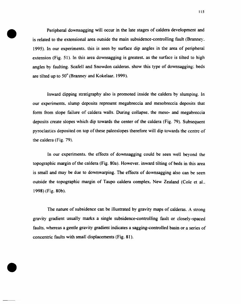
•
•
115
Peripheral downsagging will oecur in the late stages of caldera development and
is related to the extensional area outside the main subsidence~eontrolling fault (Branney.
1995). In our experiments. this is seen by surface dip angles in the area of peripheral
extension (Fig. 51). In this area downsagging is greatest. as the surfaee is tilted to high
angles by faulting. Scafell and Snowdon calderas. show this type of downsagging: beds
are tilted up to 50° (Branney and Kokelaar. 1999).
Inward dipping stratigraphy aiso is promoted inside the caldera by siumping. In
our experiments. siump deposits represent megabreccia and mesobreccia deposits that
fonn from siope failure of caldera walls. During collapse. the meso~ and megabreccia
deposits create slopes which dip towards the center of the caldera (Fig. 79). Subsequent
pyroclastics deposited on top of these paieosiopes therefore will dip towards the centre of
the caldera (Fig. 79).
[n our experiments. the effeets of downsagging could be seen well beyond the
topographie margin of the caldera (Fig. SOa). However. inward tilting of beds in this area
is small and may be due to downwarping. The effects of downsagging also can be seen
outside the topographie margin of Taupo caldera eomplex. New Zealand (Cole et al..
1995) (Fig. 80b).
The nature of subsidence ean be illustrated by gravitYmaps of calderas. A strong
gravity gradient usually marks a single subsidence~eontrolling fauIt or closely~spaced
faults. whereas a gentle gravity gradient indicates a sagging~controlled basin or a series of
concentric faults with small displaeements (Fig. 81 ).
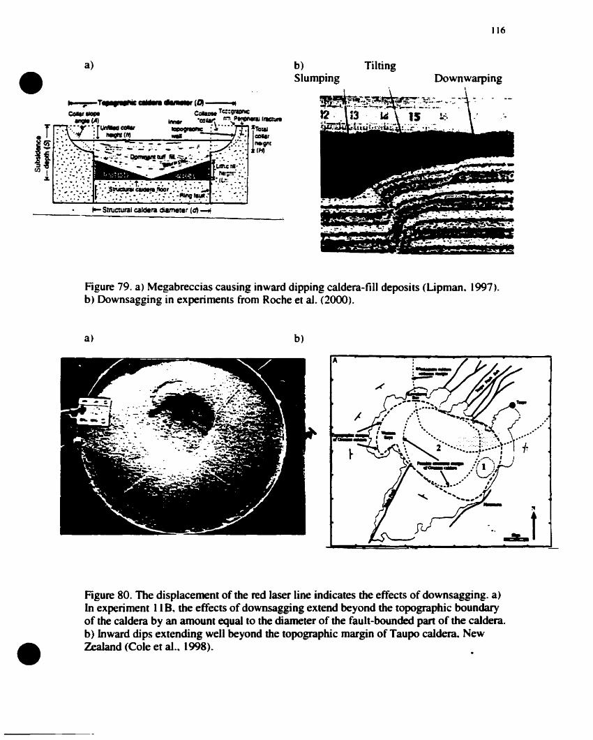
•a) Tilting
116
Figure 79. a) Megabreeeias eausing inward dipping caldera-fill deposits (Lipman. 1997).b) Downsagging in experiments from Roche et al. (2000).
a) b)
!li
........1
A
•Figure 80. The displaeement of the red laser line indicates the effects of downsagging. a)ln experiment II B. the effects of downsagging extend beyond the topographie boundaryof the ealdera by an amount equal to the diameter of the fault-bounded pan of the ealdera.b) Inward dips extending weil beyond the topographie margin of Taupo ealdera. NewZealand (Cole et al.• 1998).
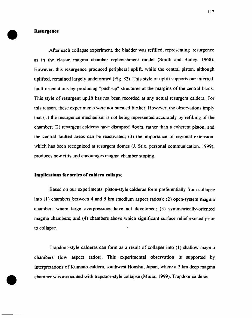
•
•
117
Resurgence
After each collapse experiment. the bladder was refilled. representing resurgence
as ln the classic magma chamber replenishment model (Smith and Bailey. 1968).
However. this resurgence produced peripheral uplift. while the central piston. although
uplifted. remained largely undefonned (Fig. 82). This style of uplift supports our inferred
fault orientations by producing "push-up" structures at the margins of the central block.
This style of resurgent uplift has not been recorded at any actual resurgent caldera. For
this reason. these experiments were not pursued further. However. the observations imply
that (1 ) the resurgence mechanism is not being represented accurately by refilling of the
chamber: (2) resurgent calderas have disrupted floors. rather than a coherent piston. and
the central faulted areas can be reactivated; (3) the importance of regional extension.
which has been recognized at resurgent domes (1. Stix. personal communication. 1999).
produces new rifts and encourages magma chamber stoping.
Implications for styles of caldera collapse
Based on our experiments. piston-style calderas form preferentially from collapse
into (1) chambers between 4 and 5 km (medium aspect ratios); (2) open-system magma
chambers where large overpressures have not developed: (3) symmetrically-oriented
magma chambers; and (4) chambers above which significant surface relief existed prior
to collapse.
Trapdoor-style calderas can form as a result of collapse into (1) shallow magma
chambers (low aspect ratios). This experimental observation is supported by
interpretations of Kumano caldera. southwest Honshu.. Japan. where a 2 km deep magma
chamber was associated with trapdoor-style collapse (Miura. (999). Trapdoor calderas
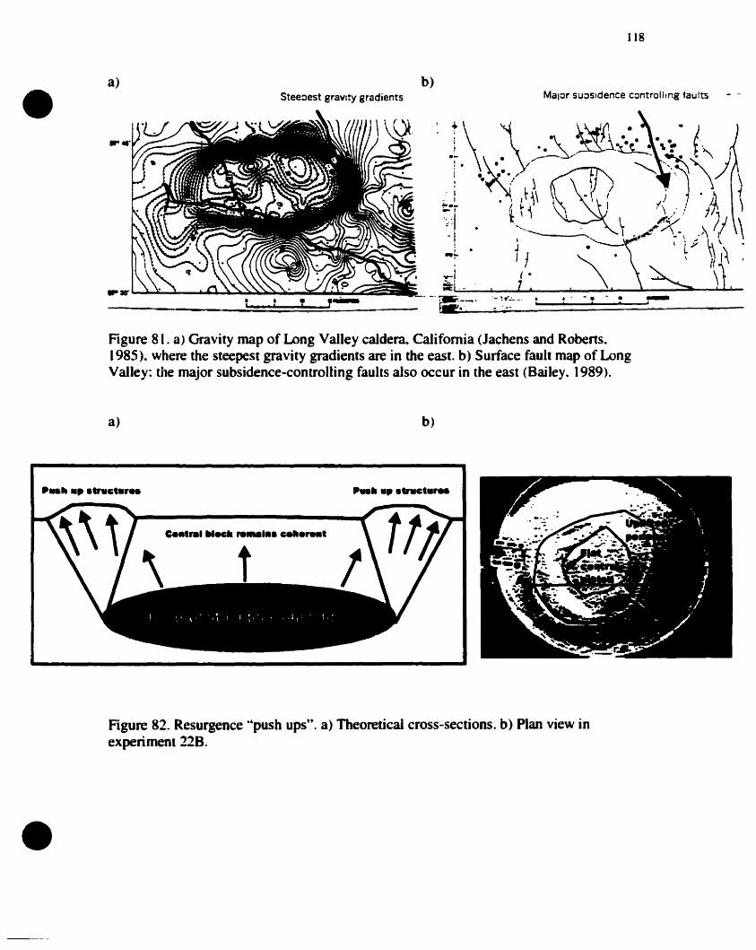
•a)
Steeoest gravlty gradients
b)
118
Major su:)sldence controlllng taults
'\.
.. -. •, , .Figure 81. a) Gravity map of Long Valley caJdera. Califomia <Jachens and Robens.1985). where the steepest gravity gradients are in the east. b) Surface fault map of LongValley: the major subsidence·controlling faults also occur in the east (Bailey. 1989).
a) b)
•
Figure 82. Resurgence o·push ups". a) Theoretical cross-sections. b) Plan view in
. "''''8expenment __ .
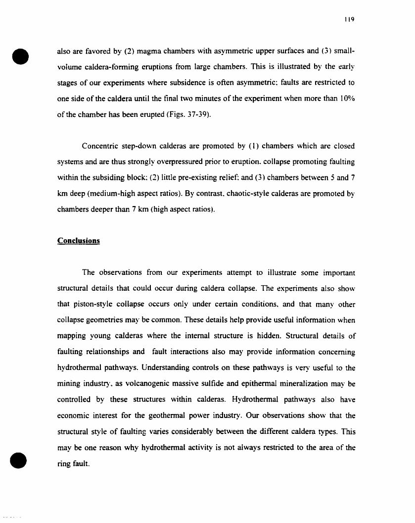
•119
also are favored by (2) magma chambers with asymmetric upper surfaces and (3) small
volume caldera-forming eruptions from large chambers. This is illustrated by the early
stages of our experiments where subsidence is often asymmetric; faults are restricted to
one side of the caldera until the tinal two minutes of the experiment when more than 100/0
of the chamber has been erupted (Figs. 37-39).
Concentric step-down calderas are promoted by (1) chambers which are closed
systems and are thus strongly overpressured prior to eruption. collapse promoting tàulting
within the subsiding block; (2) finIe pre-existing relief; and (3) chambers between 5 and 7
km deep (mediurn-high aspect ratios). By contrast. chaotic-style calderas are promoted by
chambers deeper than 7 km (high aspect ratios).
Conclusions
The observations from our experiments attempt to illustrate sorne important
structural details that could occur during caldera collapse. The experiments also show
that piston-style collapse occurs only under certain conditions. and that many other
collapse geornetries may be common. These details help provide useful information when
mapping young calderas where the internai structure is hidden. Structural details of
faulting relationships and fault interactions also May provide information conceming
hydrothermal pathways. Understanding controls on these pathways is very useful to the
mining industry. as volcanogenic massive sulfide and epithermal mineralization may be
controlled by these structures within calderas. Hydrothermal pathways also have
economic interest for the geothennal power industry. Our observations sho\v that the
structural style of faulting varies considerably between the different caldera types. This
may be one reason why hydrothermal activity is not always restricted to the area of the
• ring fault.
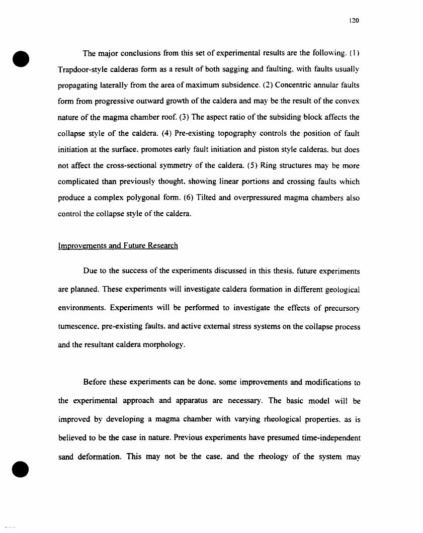
•
•
120
The major conclusions from this set of experimental results are the following. (1 )
Trapdoor-style calderas fonn as a result of both sagging and faulting. \Vith faults usually
propagating laterally from the area of maximum subsidence. (2) Concentric annular faults
form from progressive outward growth of the caldera and may be the result of the convex
nature of the magma chamber roof. (3) The aspect ratio of the subsiding block affects the
collapse style of the caldera. (4) Pre-existing topography contrais the position of fault
initiation at the surface. promotes early fault initiation and piston style calderas. but does
not affect the cross-sectional symmetry of the caldera. (5) Ring structures may be more
complicated than previously thought. sho\ving linear portions and crossing faults which
produce a complex polygonal forro. (6) Tilted and overpressured magma chambers also
control the collapse style of the caldera.
[mprovements and Future Research
Due to the success of the experiments discussed in this thesis. future experiments
are planned. These experiments will investigate caldera formation in different geological
environments. Experiments will he performed to investigate the effects of precursory
tumescence. pre-existing faults .. and active external stress systems on the collapse process
and the resultant caldera morphology.
Before these experiments can be done.. sorne improvements and modifications to
the experimental approach and apparatus are necessary. The basic model will be
improved by developing a magma chamber with varying rheological properties. as is
believed ta be the case in nature. Previous experirnents have presumed time-independent
sand deformation. This may Rot be the case.. and the rheology of the system may

•
•
121
dramatically affect the pattern of fracture development and thus the resultant
experimental calderas. By improving the scaling of viscosities of both the magma and the
wallrocks. the details of the resultant deformation should be more realistic. The
timescales of tumescence. tectonic movement. evacuation and resurgence aIso must be
scaled accurately if the deformation of the sand is found to be time-dependent.
The magma chamber will consist of water and silicone ofdifferent viscosities.
Water will represent hot magma and will be contained in a thick silicone jacket rath~r
than the rubber bladder previously used. The silicone jacket will represent the highly
viscous crystal mush that may represent a large proponion of the magma chamber.
particularly at its base and margins (Marsh. 2000). A data acquisition board and
peripherals will al10w the pressure within the chamber to be monitored continuously and
scaled correctly. since results from this thesis showed that magma chamber pressure \\as
an important control on the caldera morphology.
ln addition to the viscosity variability in the area immediately around the magma
chamber. the crustal block above the magma chamber also may have signilil.:ant
rheological differences (Burov and Guillou-Frottier. 1999). These rheological diflt:r~nl.:t:s
are shown by the ductile-to-brinle transition~ which can be represented in the modd h~
introducing a lower layer of mixed sand and clay representing a more ductile lay~r rdatt:d
to the magma chamber. and an overlying layer of pure sand representing a mor~ hrittle
surface layer. Both layers will obey the appropriate scaling considerations.
•
•
122
A further improvement to the basic model will he the addition of material to the
subsiding block: this material will represent the emplacement of ignimbrite sheets \vithin
the caldera as it is subsiding. Volumes~ rates. and densities \vill be calculated according to
the scaling considerations and the water evacuation rate from the chamber. The mass of
this material may have an important effect on the caldera fonning process and fault
formation at the surface (Burov and Guillou-Fronier. 1999).
For each group of experiments. we will perform several using layered sands.
Sections of these sands will be sampled after the experiment in order to reveal the
internai caldera structure of the model. The layering of the sand is time-consuming. and
tûr this reason only selected experiments will be chosen for sectioning.
The first set of experiments will use both the shallo\v magma chamber and a deep.
large-scale tumescent source to create precursory doming prior to collapse. Firstly. the
effect of precursory tumescence related to the main shallow chamber \vill be investigated.
Before collapse is initiated. a dome will be created by the addition of water ta the shallow
chamber. Secondly. the effect of precursory tumescence related to a deeper source will he
investigated. A large deep inflatable chamber will be introduced belo\v the pre-inflated
shallow chamber. This lower chamber will be gradually inflated prior to collapse.
The second set of experiments will involve pre-existing faults: specifically. the
effects of these faults on the collapse process in the absence of an external stress field
will be investigated. Firstly, the effect on collapse style of single faults. their dip
•
•
1, ..-.)
directions and spatial location will be investigated. Isolated linear faults. whose dip
directions are vertical~ steeply inward or steeply outward dipping. will be introduced in
various locations above magma chamber; collapse then will be initiated. Secondly. the
effect on collapse style of parallel and cross-cutting multiple faults will be investigated.
In contrast to the experiments involving isolated faults~ initially a series of parallel linear
faults also ~;ll be introduced~ the spacing of which \vill be varied. in order to examine the
effects of fault density on the collapse process. Further experiments will involve multiple
cross-cutting faults.
The third set of experiments will use mobile walls to create an extemal stress tield
that is active prior to or during collapse. Firstly. the effect of extension and precursory
rifting on collapse style will be investigated. Mobile walls will allow the production of an
active rift prior to and during collapse. Caldera collapse will be initiated at various stages
during the rifting process. e.g.. during early stages of rifting (narrow rifts) as opposed to
mature. wider rifts. Secondly. the effeet of precursory pull-apart basins on collapse style
will be investigated. Mobile walls and strike slip motion between basal plates will allow
the formation of an active pull-apart basin prior to and during collapse. Similar to the
rifting experiments't caldera collapse will he initiated at various stages during the
development of the pull-apart basin.
The fourth set of experiments will investigate the effects of resurgence on the
caldera structure. Firstly't the effect of regional detumescence on collapse style \vill be
•
•
124
investigated. The lower tumescent source~ as previously described above. will be deflated
to observe the effects at the surface. Secondly. the effect on collapse style of re-inflation
of the main magma chamber will he investigated. The main magma chamber will be
refilled after collapse of the caldera. This refilling could represent a simple replenishment
of magma or a volume increase in the chamber caused by magma input and/or
vesiculation. Thirdly. the effect of sill intrusion above the chamber on collapse style will
be investigated. A series of small. sill-like chambers will be introduced and intlated
above the main chamber. and their effect at the surface will be observed. Fourthly. the
etTect of resurgent doming on the different caldera types ",oil1 be investigated. These
experiments will he performed on the different caldera types created in previous
experiments. This approach will help to isolate the effects of caldera structure on the style
of resurgent doming.
•
•
125
REFERENCES
Acocella. V.. and R. Funiciello, The interaction between regional and local tectonicsduring resurgent doming: the case of the island Ischia. Italy. J Vo/canol. Geolherm. Res..88.109-123.1999.
Anderson. E.M.. The dynamics of the formation of cone-sheets. ring dykes and cauldronsusbsidences. Proc. R. Soc. Edinburgh. 56.128-157.1936.
Aramaki. S.. Formation of the Aira caldera. southern Kyushu. -22000 years ago. 1.Geophys. Res.. 89. 8485-8501. 1984.
Bacon. C.. Eruptive history of Mount Mazama and Crater lake caldera.. Cascade range.U.S.A. J. Vo/canol. Geolherm. Res.• 18.57-115. 1983.
Bailey R. A.. Geological map of the Long Valley caldera. Mono-Inyo craters volcanicchain. and vicinity. Eastern California. Miscellaneous Investigations Series. Departmentof the (nterior. V.S. Geological Survey. Map 1-933. 1989.
Bailey R. A.. G. B. Dalrymple. and M. A. Lanphere. Volcanism. structure. andgeochronology of Long Valley caldera. California. 1. Geophys. Res.. 81. 725-744. 1976.
Barben. F.. F. Innocenti. P. Landi. U. Rossi. M. Saïta. R. Santacroce. and LM. Villa. Theevolution of Latera caldera (Central Italy) in the light of subsurface data. Bull. Vo/cano!..47-1.125-141.1984.
Bower. S.. and A. Woods. Control of magma volatile content and chamber depth on themass erupted during explosive volcanic eruptions. 1. Geophys. Res.. 102. 10 .273-10.290.1997.
Branney. M.).. and P. Kokelaar. Volcanotectonic faulting.. soft state deformation. andrheomorphism of tuffs during development of a piecemeaI caldera. English Lake District.Geol. Soc. Am. Bull.. 106. 507-530. 1994.
Branney. l'vl.).• Downsag and extension al calderas. New perspectives on collapsegeometries from ice melt. mining and volcanic subsidence. Bull. Vo/canol.. 57.303-318.1995.
Branney M.J.. and P. Kokelaar.. Inside silicic calderas. Interactions of calderadevelopment. tectonism and hydrovolcanism. Field Guidebook of the I.A.V.C.E.1.Commission on Explosive Volcanism field workshop. 7-18 July 1999. 152 pp 6 colourplates.
Burov E.B. and L. Guillou-Frottier., Thermomechanical behaviour of large ash flowcalderas. J. ofGeophys. Res., 104., 23.081- 23 .. 109. 1999
•
•
126
Chesner, C.A., and. W.I. Rose Stratigraphy of the Toba Tuffs and the evolution of theToba Caldera Complex. Sumatra. Indonesia. Bull. Vo/canol.. 53. 343-356. 1991.
Clough, C.T.. H.B. Maufe. and E.R. Bailey. The cauldron subsidence of Glencoe and theassociated igneous phenomena. Q. J Geol. Soc. London. 65. 611-678.1909.
Cole, J.W., S.J.A. Brown. R.M. Burt. S.W. Beresford. and C.J.N. Wilson. Lithic types inignimbrites as a guide to the evolution of a caldera complex. Taupo volcanic centre. Ne\\'Zealand.J Vo/canol. Geotherm. Res.. 80.217-237.1998.
Chadwick. W.W.. and K.A. Howard. The pattern of eireumferential and radial eruptivefissure on the volcanoes of Fernandina and Isabela islands. Galapagos. Bull. Volcanol..53.259-275. 1991.
Chadwick Jr. W.W.. and J.H. Dieterich. Mechanical modeling of cireumferential andradial dike intrusion on Galapagos volcanoes. J Vo/canol. Geotherm. Res.. 66. 37-51.1995.
Christiansen. R.L.. Yellowstone magmatic evolution: hs bearing on understanding largevolume explosive volcanism. Studies in Geophysics/Explosive volcanism: Inception.Evolution. and Hazards. Washington D.C. National Academie Press. 84-95. 1984.
Druitt. T.• and R.S.J. Sparks. On the formation ofcalderas during ignimbrite eruptions.lVature. 310. 679-681. 1984.
Ekstrom. G., Anomolous earthquakes on volcano ring-fault structures. Earth Planet. Sci.Lett.. 128.707-712.1994.
Elston, W.E.. Mid-Tertiary ash flow tuff cauldrons. southwestem New ~fexico. JGeophys. Res.. 89. 8733-8750. 1984.
Fouqué. F.. Santorin et ses Eruptions. Paris. Masson. 440 pp.. 1879.
Francis, P.. Caldera complexes and complex calderas. Volcanoes a Planetary·Perspective. Oxford. Oxford University Press. 291-32 L 1993.
Fridrich! C.J., R.P. Smith, E.n. DeWitt, and E.H. McKee. Structural, eruptive, andintrusive evolution of Grizzly Peak caldera. Sawatch range, Colorado. Geol. Soc. Am.Bull.• 103, 1160-1170, 1991.
Geist, D., K.A. Howard, A.M. Jellinek, and S. Rayder. The volcanic history of VolcanAlcedo. Galapagos Archipelago: A case study ofrhyolitic ocean volcanism. Bull.Vo/canol.. 56. 243-260. 1994.
Gudmundsson~ A.~ Formation ofcollapse calderas. Geology. 16~ 808-810. 1988.
•
•
[27
Gudmundsson. A., J. Marti. and E. Turon. Stress field generating ring faults in volcanoes.Geophys. Res. Leu.. 24. 1559-1562. 1997.
Gudmundsson. A.. Formation and development ofnonnal fault calderas and the initiationof large explosive eruptions. Bull. Vo/cano/.. 60. 160-170. 1998.
Hallinan. S.. Non-chaotic collapse at funnel caldera: Gravity study of the ring fractures ofthe Guayabo caldera.. Costa Rica.. Ge%gy. 21. 367-370.. 1993.
Hallinan. S... and G. Brown.. Incrementai collapse and stratocone growth within a tùnnelshaped caldera.. Guayabo. Costa Rica.J. Vo/canol. Geotherm. Res.. 67:101-122.1995.
Hess. K.U.. and D.B. Dingwell. Viscosities ofhydrous leucogranitic melts: A oonArrhenian model. Am. Alineral.. 81. 1297-1300. 1996.
Jachens. R.C.. and W. Roberts. Temporal and areal gravity investigations at Long Valleycaldera. California. J. Geophys. Res.. 90. Il 210-11 218. 1985.
Jacobson.. R.R.E.. W.N. MacLeod.. R. Black. Ring complexes in the Younger Graniteprovince of northem Nigeria. Geol. Soc. London A'!em. 1. 71p. 1958.
Jaupart. C .. and C. Allegre. Gas content. eruption rate and instabilities of eruption regimein silicic volcanoes. Earth Planet. Sei. Lett. 102. 413-429. 1990.
Kamata. H.. Shishimuta caldera. the buried zone of the Yabakei pyroclastic flow in theHohi volcanic zone.. Japan. Bull. Vo/cano/.. 51.41-50. 1989.
Komuro. H... Y. Fujita. and K. Kodama. Numerical and experimental models on theformation of collapse basins during the Green Tuff Orogensis of Japan. Bull. Volc'lnul..47. 649-666. 1984.
Komuro H.. Experiment on cauldron foonation: A polygonal cauldron and ring fractures.J. Va/cano1. Geotherm. Res.• 31, 131-149, 1987.
Kennedy. B.. J. Stix. J. Vallance. and Y. Lavallée.Controls oncaldera stucture andmorphology results from experimental simulations. EOS. Trans. Am. Geophys.Union. 46.FI121.
Lagabrielle Y. and Garel E., ExtensionaI faulting and caldera collapse in the axial regionof fast spreading ridges: analogue modeling. Submined to J. Geopbys. Res... 2000.
Lipman! P.W.! The roots ofash flow calderas in western North America: windows iotothe tops of granitic batholiths! J. Geophys. Res., 89. 8801-8841. 1984.
Lipman~ P.W,! Subsidence ofash flow calderas: Relation to caldera size and magmachamber geometry, Bull. Va/canol.. 59. 198-218. 1997.
•
•
128
Lipman, P.W.. Calderas. In: H. Sigurdsson.. B. Houghton. S. MeNutt.. H. Rymer.. and J.Stix (Editors).. Encyc/opedia of vo/canoes. San Diego. Academie Press pp. 643-662.2000.
Marsh. B.. On the mechanics of caldera resurgenee.. J. Geophys. Res.. 89. 8245- 8241.1984.
Marsh. B.• 2000 Magma Chambers. In: H. Sigurdsson. B. Houghton. S. McNutt. H.Rymer. and J. Stix (Editors). Encyclopedia ofvo/canoes. San Diego. Academie Press pp.191-206. 2000.
Marti. J.. G.J. Albay.. L.T. Redshaw.. and R.S.J. Sparks, Experimental study of collapsecalderas. J. Geol. Soc. London.. 151. 919-929. 1994.
MassoI. H.. and C. Jaupart. The generation of gas overpressure in volcanic eruptions..Earth and Planelary Science let.. 166. 57-70. 1999.
McConnell V.S.• C. K. Shearer. J.C. Eiehelberger. M. J. Keskinen. P.W. Layer. and J. J.Papike. Rhyolite intrusions in the intraealdera Bishop Tuff. Long Valley Caldera.Califomia. J. Volcanol. Geotherm. Res.. 67.41-60.. 1995.
~tcLeod .. P.. The role of magma buoyaney in caldera forming eruptions. Geophys, Re."",Lei.. 26. 2299-2302.. 1999.
Merle. O.. and A. Borgia. Sealed Experiments ofvolcanic spreading.. J Geophys. Res ..101. 805- 817.1996.
Miura. D.. and M. Tamai.. Intracaldera structure and megabreeeias at Dorobu caldera.northwestem Honshu. Japan.. J. Volcanol. Geolherm. Res.. 80. 195-215. 1997.
Miura. D... Arcuate pyroclastic conduits. ring faults .. and coherent floor at Kumanocaldera. southwest Honshu.. Japan. J. Volcano/. Geotherm. Res.. 92.. 271-294. 1999.
~Ioore .. 1. .. and P. Kokelaar, Tectonically eontrolled pieeemeal ealdera eollapse. alGleneoe volcano, Scotland. Geol. Soc. Am. Bull... 110.. 1448-1466. 1998.
Mori.. J... and C. McKee, Otward-dipping ring-fault structure at Rabaul caldera as ShCl\\TI
by earthquake locations.. Science.. 235 .. 193-194.. 1987.
Mori. J... R. A. White, D. H. Harlow.. P. Okubo. J. A. Power. R. P. Hoblin, E. P. Laguerta.A. Lanuza. and B. C. Batistuta.. Volcanie earthquakes follo\ving the 1991 climacticeruption of Mt. Pinatubo: Strong seismieity during a waning eruption. Fire and .\;/ud:Eruptions and Lahars ofkit. Pinatubo, Philippines. Seattle, University ofWashingtonPress, 339-350, 1996.
•129
Munro, D.C., and S.K. Rowland, CaJdera morphology in the western Galâpagos andimplications for volcano eruptive behavior and mechanism of caledera formation. J.Vo/canol. Geotherm. Res.• 72,85·100,1995.
Nelson, C.H.• C.R. Bacon. S.W. Robinson. D.P. Adam. J.P. Bradbury. J.H.Barber. Jr.. D.Schwartz. and G. Vagenas. The volcanic, sedimentologic. and paleolimnologic history ofthe Crater Lake caldera tloor, Oregon: Evidence for smail caldera evolution. Geol. Soc.Am. Bull.• 106. 684-704, 1994.
Nielson. D.L.. and J.B. Hulen. Internai geology and evolution of the Redondo dome.Valles caldera. New Mexico. J Geophys. Res.. 89. 8695-8711. 1984.
Odonne. F., I. Ménard. G.J. Massonnat, and J.-P. Rolando. Abnormal reverse faultingabove a depleting reservoir. Ge%gy. 27,111-114. 1999.
Oftedahl. C.. Cauldrons of the Permian Oslo rift. J Va/cano1. Geotherm. Res.. 3. 343371, 1978.
Roche. O.. T.H. Druitt. and O. Merle. Experimental study of caldera formation. JGeophys. Res.. 105. 395-416. 2000.
Sandtord. A.L.. Analytical and experimental study of simple geologic structures. Geol.Soc. Am. Bul/.. 70. 19·52. 1959.
Sawada.. Y.. Subterranean structure of collapse caldera associated with andesitic anddacitic eruptions: Structural evolution of the Miocene Kakeya cauldron. southwest Japan.Bull. Vo/canol. . 47.551-568. 1984.
Scandone. R.. Chaotic collapse of calderas. J. Vo/canol. Geo{herm. Res.. 42. 285-302.1990.
Schimick. C.. P. Van der Bogaard. and H. Schmincke. Cone sheet formation andintrusive growth of an oceanic island- The Miocene Tejeda complex on Gran Canaria(Canary Islands). Ge%gy. 27. 207-210. 1999.
Schultz. R.A.• Relative scale and the strength and defonnability of rock masses. J Sin/cl.GeaI., 18. 1139-1149,1996.
Self, S., and P.W. Lipman. Large ignimbrites and caldera-forming eruptions. IAVCEIworking group on explosive volcanism and its products. Field workshop (11 WA) inJemez Mountains. New Mexico, and San Juan Mountains. Colorado. 128. 1989.
Sk.illing~ I.P.. Incrementai caldera collapse of Suswa volcano. Gregory Rift Valley.Kenya~ J. Geol. Soc. London. 150,885-896. 1993.
•
•
130
Simkin~ T.. and K.A. Howard~ Caldera collapse in the GaJapagos Islands. 1968. Science.169.429-437,1970.
Smith, R.L.. Ash flow magmatism. Geol. Soc. Am.• Spec. Pop. 180. 5-27. 1979.
Smith. R.L.. and R.A. Bailey. Resurgent cauldrons. Geol. Soc. Am. i\-rfem.. 116. 83-104.1968.
Spera.. f.l .. and J.A. Crisp. Eruption volume.. periodicity. and caldera area: Relationshipsand inferences on the development on compositional zoning in silicie magma chambers.J. Vo/canol. Geotherm. Res.. Il. 169-187.1981.
Takahashi.. M... Anatomy ofa middle Miocene Valles-type caldera cluster: Geology of theOkeueyama volcano-plutonic complex.. southwest Japan. J. Vocanol. Geotherm. Res.. 19.33-70. 1986.
Tait S.. C. Jaupart. and S. Vergniolle. Pressure. gas content and eruption periodicity of ashallow erystallizing magma chamber. Earth Planet. Sci. Leu. 92.. 107-123 .. 1989.
Ventura. G.. Tectonics. structural evolution and caldera formation on Vulcano Island(Aeolian Archipelago. southem Tyrrhenian Sea). J. Volcanol. Geotherm. Res.. 60. 107124. 1994.
Walker. G.P.L.. Downsag caJderas.. ring faults. caldera sizes and incremental calderagro\vth. J. Geophys. Res.. 89. 8407-8416. 1984.
Walker. G.P.L.. Three Hawaiian calderas: an ongin through loading by shallowintrusions? J. Geophys. Res.. 93. 14 773-14 784. 1988.
Watson. E.B.. Diffusion in volatile-bearing magmas, Rev. in Mineral.. vol. 30. 371-411.1994.
Westrich, H.R.. and T.M. Gerlach, Magmatic gas source for the stratospheric S02 cloudfrom the lune 15, 1991. eruption of Mount Pinatubo, Geology, 20. 867-870.1992.
Williams. H.• Calderas and their ongin. Bull. 25. pp.239-346. Dep. OfGeol. Sei.. Uni\'.of Calif.. Berkley. 1941.
Wilson. C.l.N., and W. Hildreth. The Bishop Tuff: New insights from eruptivestratigraphy, J. Geai., IDS. 407-439, 1997.
Withjack, M.O., and Scheiner, C.., Fault patterns associated with dornes-An experimentaIand analytical study. Am. Assoc. Petro/. Geo/. Bull., 66,302-316. 1982.
Yokoyama., L, and S. De la Cruz-Reyna.. Comments on ··Chaotic collapse ofcalderas" byR. Scandone., J. Vo/canol. Geotherm. Res.• 47. 349-357. 1991 .

•
•
Yoshida~ T.. Tertiary Ishizuki. cauldron.. southwestem Japan arc: formation by ringfracture subsidence.. .J Geophys. Res.• 89. 8502-8510.1984.
131