Embed Size (px)
Citation preview
*Corresponding author, e-mail: [email protected]
Research Article GU J Sci 31(3): 846-861 (2018)
Gazi University
Journal of Science
http://dergipark.gov.tr/gujs
Compensation of Harmonics in Neutral Current Using Active Power Filter for
Three Phase Four Wire System
Rajendrasinh JADEJA1,*, Akash FALDU1, Tapankumar TRIVEDI1, Siddharthsingh CHAUHAN2, Vinod PATEL3
1Marwadi Education Foundation’s Group of Institutions, Rajkot, Department of Electrical Engineering, Rajkot-Morbi Highway, Gauridad,
Gujarat, India-360003
2Nirma University, Institute of Technology, Ahmedabad- Gandhinagar Highway, Ahmedabad, Gujarat, India-382481
3Amtech Electronics India Ltd., Nr Kh-5 Circle, Sector-28, Gandhinagar, Gujarat, India-382027
Article Info
Abstract
Increased penetration of nonlinear loads like power electronic converter based systems have
aggravated issue of harmonic injection in the power system. Neutral current harmonics is an
issue of concern for three phase four wire system. This paper is focused on the elimination of
neutral current harmonics with the help of shunt active power filter based on the star-delta
transformer and single phase half bridge inverter. The presented active power filter eliminates
harmonics present in neutral current which in turn helps in mitigating third harmonics from the
supply mains. The topology has the advantage of reduced number of semiconducting devices
and switching losses as compared to conventional three phase active filter. Simulation studies
for the proposed active filter are presented and compared with the behavior of conventional
three phase active filter. Experimental results for DSP based laboratory prototype of the
proposed filter are shown to substantiate performance of system. Both simulations, as well as
experimental results, demonstrate effective compensation provided by single phase half bridge
inverter based active filter.
Received: 10/03/2017 Accepted: 12/05/2018
Keywords
Active Power Filter
Harmonics Neutral Current
1. INTRODUCTION
With the growth of active and nonlinear loads, including the increasing number of static power converters
and arc furnaces just to mention part of the problem, the performance has been considered as an essential
component in a power distribution installation [1]. Because of the presence of large number single phase
loads in three phase four wire systems, substantial amounts of triplen harmonics are also produced in
addition to other harmonics. The distorted load current even in the case of balanced loading condition
leads to flow of neutral current. While increased lower order harmonics affect the overall performance of
utility, the presence of triplen harmonics in the power line results in following problems:
1. Greater power losses due to higher harmonic currents on the source side.
2. Interference in the communication system.
3. Overheating of Neutral Conductor and/or severe damage to conductor
It is reported in a survey that 22.6% of the sites that have more no. of computer and single phase non-
linear loads show neutral current in excess of 100% of the phase current due to zero sequence nature of
triplen harmonics [2]. It is also reported that increased no. of neutral conductor failure is as a result of
flow of triplen harmonics in the system. Additionally, the flow of harmonics affects the sensitive
electronics equipment [3]. This makes it essential to eliminate neutral current harmonic from the system.
Passive filters have been conventionally used to control the flow of harmonics in the system.
847 Rajendrasinh JADEJA et al./ GU J Sci, 31(3): 846-861 (2018)
Passive harmonic filters comprise of passive components and are connected either in series/parallel
combinations for mitigation of harmonics. They have disadvantages like limited compensation, bulky,
etc. Active power filter (APF) is used to solve these issues [4-11]. The active harmonic filter is designed
and controlled such that current and/or voltage harmonics components are injected 1800 out of phase
resulting in elimination of compensation of harmonic components. In addition to this, active power filters
can also compensate reactive power, regulate terminal voltage, suppress flicker and improve voltage
balance in three wire as well as four wire systems. For neutral current harmonic elimination, traditionally
active power filters based on three-phase, four-wire inverter topology is implemented [12, 13]. A
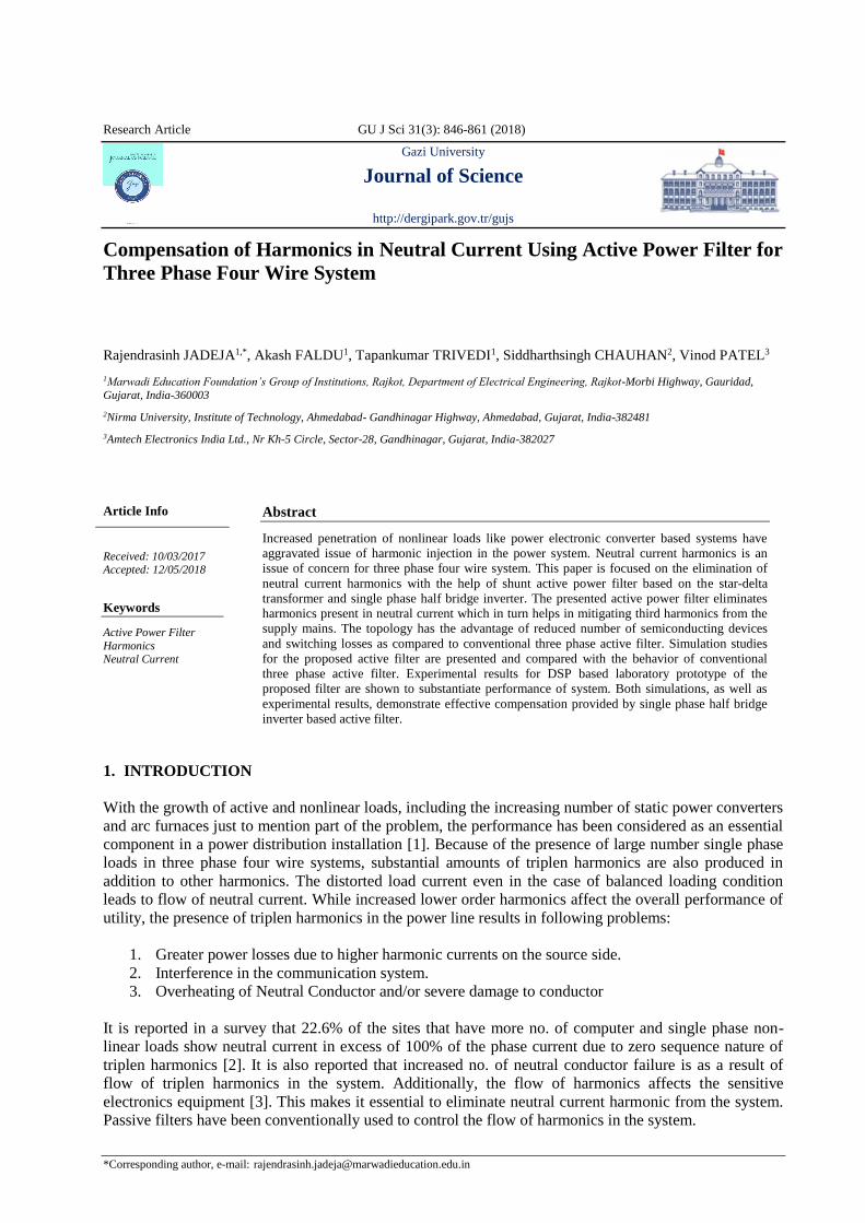
conventional three phase four wire split capacitor based topology is shown in Figure 1. On the other hand,
Transformer configurations for neutral current compensation have been reported in [14, 15]. While zig-
zag transformer based three phase inverter topology for compensation in three phase four wire is popular
[16], it requires additional winding for the realization of zig zag transformer. A T-connected transformer
based topology is proposed for harmonic reduction and neutral current reduction in [17]. The topology
not only requires three phase inverter but has complex control strategy. The use of transformers along
with APF for elimination of neutral current harmonics helps in reducing the rating of inverter topology
used for APF. However, most of the topologies which compensate triplen and as well as other harmonics
have disadvantages in terms of:
• Increased DC link voltage value (≈1.75VLL) which in turn increases rating of switches
• Increased switching losses
• More no. of switches
Additionally, use of magnetics will result in increased losses. This necessitates topology which uses less
no. of switches to justify efficiency of the overall system. On the other hand, flow of triplen harmonics in
the distribution system may be local phenomena where compensation of neutral current is essential while
TDD is still within limits for given short circuit capacity. The current topology is a feasible solution
where problems due to excessive third harmonics affect the overall performance of the system.
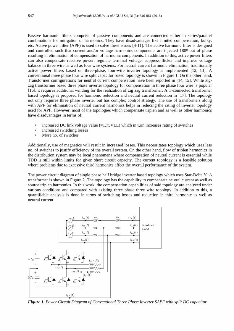
The power circuit diagram of single phase half bridge inverter based topology which uses Star-Delta Y−Δ
transformer is shown in Figure 2. The topology has the capability to compensate neutral current as well as
source triplen harmonics. In this work, the compensation capabilities of said topology are analyzed under
various conditions and compared with existing three phase three wire topology. In addition to this, a
quantifiable analysis is done in terms of switching losses and reduction in third harmonic as well as
neutral current.
Figure 1. Power Circuit Diagram of Conventional Three Phase Inverter SAPF with split DC capacitor
848 Rajendrasinh JADEJA et al./ GU J Sci, 31(3): 846-861 (2018)
Figure 2. Power Circuit Diagram of Single Phase Half Bridge Inverter based SAPF
The control of SAPF is crucial to generating effective compensating current for removal of third
harmonics from the system. The presented SAPF has simple as well as an effective active filtering
technique, thus compensating the neutral current and simultaneously reducing total harmonic distortion
(THD) of the system. To emphasize the concept, the performance of proposed SAPF is compared with
conventional three-phase SAPF. Simulation, as well as experimental studies, are presented to show
effectiveness of the SAPF. The paper is organized as follows: The compensation principle of half bridge
inverter based SAPF is described in section-II. The control philosophy and design of the system are key
points for feasibility of the topology. Hence, Design of the topology is presented in section III which is
followed by control strategy and flow chart for digital implementation in section IV. Simulation is carried
out and essential comparison is shown in section-V. The experimental prototype and results with neutral
current compensation limiter are described in section VI which is followed by conclusion.
2. COMPENSATION PRINCIPLE OF HALF BRIDGE INVERTER BASED SAPF
The three-phase distorted current waveform are given by,
1 12
( )
a a a an ann
i t I sin t I sin n t (1)
1 12
2 2( )
3 3
b b b bn bnn
i t I sin t I sin n t (2)
1 12
2 2( )
3 3
c c c cn cnn
i t I sin t I sin n t (3)
In addition to this, the neutral current in case of three phase four wire system is given by,
( ) ( ) ( ) ( ) n a b ci t i t i t i t (4)
849 Rajendrasinh JADEJA et al./ GU J Sci, 31(3): 846-861 (2018)
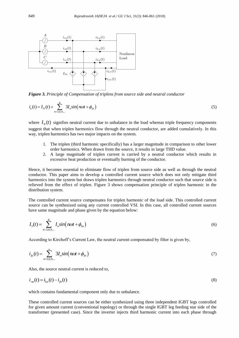
Figure 3. Principle of Compensation of triplens from source side and neutral conductor
8
33,6,9,...
( ) ( ) 3
n N n nn
i t I t I sin n t (5)
where ( )NI t signifies neutral current due to unbalance in the load whereas triple frequency components
suggest that when triplen harmonics flow through the neutral conductor, are added cumulatively. In this
way, triplen harmonics has two major impacts on the system.
1. The triplen (third harmonic specifically) has a larger magnitude in comparison to other lower
order harmonics. When drawn from the source, it results in large THD value.
2. A large magnitude of triplen current is carried by a neutral conductor which results in
excessive heat production or eventually burning of the conductor.
Hence, it becomes essential to eliminate flow of triplen from source side as well as through the neutral
conductor. This paper aims to develop a controlled current source which does not only mitigate third
harmonics into the system but draws triplen harmonics through neutral conductor such that source side is
relieved from the effect of triplen. Figure 3 shows compensation principle of triplen harmonic in the
distribution system.
The controlled current source compensates for triplen harmonic of the load side. This controlled current
source can be synthesized using any current controlled VSI. In this case, all controlled current sources
have same magnitude and phase given by the equation below:
8
3 33,6,9,...
( )
n nn
I t I sin n t (6)
According to Kirchoff’s Current Law, the neutral current compensated by filter is given by,
33,6,9,...
( ) 3
fa n nn
i t I sin n t (7)
Also, the source neutral current is reduced to,
( ) ( ) ( ) sa Ln fni t i t i t (8)
which contains fundamental component only due to unbalance.
These controlled current sources can be either synthesized using three independent IGBT legs controlled
for given amount current (conventional topology) or through the single IGBT leg feeding star side of the
transformer (presented case). Since the inverter injects third harmonic current into each phase through
850 Rajendrasinh JADEJA et al./ GU J Sci, 31(3): 846-861 (2018)
neutral point of star side of transformer, which is 1/3rd of the total neutral current, phase current values
will be revised to,
1 1 32 3,6,9,...
( )
a a a an an n nn n
i t I sin t I sin n t I sin n t (9)
1 1 32 3,6,9;...
2 2( )
3 3
b b b bn an n nn n
i t I sin t I sin n t I sin n t (10)
1 1 32 3,6,9;...
2 2( )
3 3
c c c cn cn n nn n
i t I sin t I sin n t I sin n t (11)
In this work, the objective of the inverter is to supply triplen current to the load. Hence, it becomes
necessary to extract triplen components which can be easily attained through Notch Filter. The transfer
function of the notch filter is given by,
2 2
0
2 200
( )
zH sH s
s sQ
(12)
The zero frequency ωz and pole frequency ω0 are made equal to realize the standard notch filter. In this
work, the filter is realized using the digital processor. This can be done by substituting Laplace operator
with
2 1
1
s
zs
T z (13)
Here, Ts is the sampling frequency of algorithm. The Eq. (12) is revised to
2
1 202
0
2002
1 20
2 20 00 0
11
1( )
2 22 2
1
2 2 2 2
s
s
Tz z
TH z
Qz z
Q Q
(14)
The appropriate value of pole frequency ω0 and width Q are taken as 314.16 rad/sec and 2.5 respectively.
The value of Ts depends on switching frequency of the system. The final transfer function for the given
system is,
1 2
0
1 2
1 0.90356430( )
1 1.994859444 0.994920081
H z zH z
z z (15)
3. DESIGN OF HALF BRIDGE INVERTER BASED SAPF
Considering the line to line source RMS voltage of Vs=415V, the phase voltage value is obtained as,
Vph=240V. A single phase nonlinear load is connected between one each phase and a neutral terminal.
The value of load resistance is taken as Rd=35Ω and filter components on DC side of the load are taken as
851 Rajendrasinh JADEJA et al./ GU J Sci, 31(3): 846-861 (2018)
Ld=2.5mH and Cd=470μF. After extracting third harmonic component from the load current, it is found
that the value is I3=8.3A.
The absolute rating of transformer used for compensation purpose will be
33
3 240 8.3
phS V I
S (16)
The absolute rating of the transformer is taken as S=5.976kVA. In addition to supplying harmonics, the
star-delta (Y/Δ) transformer also feeds negligible amount of active power to maintain DC link. Hence,
suitable de-rating is done which leads to transformer rating of 6.5 kVA. The transformer employed is a 2:1
transformer resulting into the voltage value of 120V on the secondary side (Delta side).
3.1. DC Capacitor Value
The dc side capacitors are designed to have minimum ripple in the output voltage. Based on the value of
peak to peak voltage ΔVpp, and frequency of rectifier, the filter value is calculated as:
3
p
pp
IV
C
In order to limit voltage ripple to 5% of the total voltage and current ripple to 50A, the capacitor value is
506241
3 314.16 8.5
C F
Due to availability, two 12mF capacitors are connected in series to obtain 6mF of capacitance.
3.2. Filter Inductor
The appropriate value of filter inductor used for coupling the inverter to neutral point of the transformer is
decided based on the DC link voltage value Vdc, modulation index mn, switching frequency fsw and current
ripple. The equation for filer inductor is given by,
0.5
6
dc n
f
sw N
V mL
f I (17)
Considering the DC link voltage of Vdc=170V, modulation index mn=0.7, switching frequency fsw of 5 kHz
and neutral current error ΔIN of 0.8A, the value of total filter inductance is given by Lf=2.48 mH is
obtained. Since the leakage inductance offered by the transformer is taken as 1.5 mH on 0.02 pu basis, an
external inductance of 1 mH is selected.
4. OPERATION OF SHUNT ACTIVE POWER FILTER
4.1. Half Bridge Inverter Based SAPF
A three phase inverter based SAPF requires six switches and corresponding gate driver circuits. Similar
performance for mitigation of triplen harmonics is achieved by the SAPF topology which utilizes a star-
delta transformer along with half bridge inverter [4]. As shown in Figure 2, star connected primary
winding of the transformer is connected to the supply while delta connected secondary is linked to three-
phase half bridge rectifier of the APF. The neutral current (iLn(t)) from the load neutral terminal is forced
to flow through the half bridge inverter and is denoted as (ifN(t)). Under steady state condition, the same
852 Rajendrasinh JADEJA et al./ GU J Sci, 31(3): 846-861 (2018)
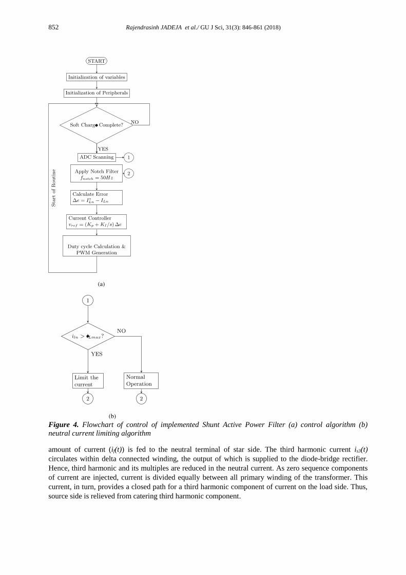
Figure 4. Flowchart of control of implemented Shunt Active Power Filter (a) control algorithm (b)
neutral current limiting algorithm
amount of current (if(t)) is fed to the neutral terminal of star side. The third harmonic current is3(t)
circulates within delta connected winding, the output of which is supplied to the diode-bridge rectifier.
Hence, third harmonic and its multiples are reduced in the neutral current. As zero sequence components
of current are injected, current is divided equally between all primary winding of the transformer. This
current, in turn, provides a closed path for a third harmonic component of current on the load side. Thus,
source side is relieved from catering third harmonic component.
853 Rajendrasinh JADEJA et al./ GU J Sci, 31(3): 846-861 (2018)
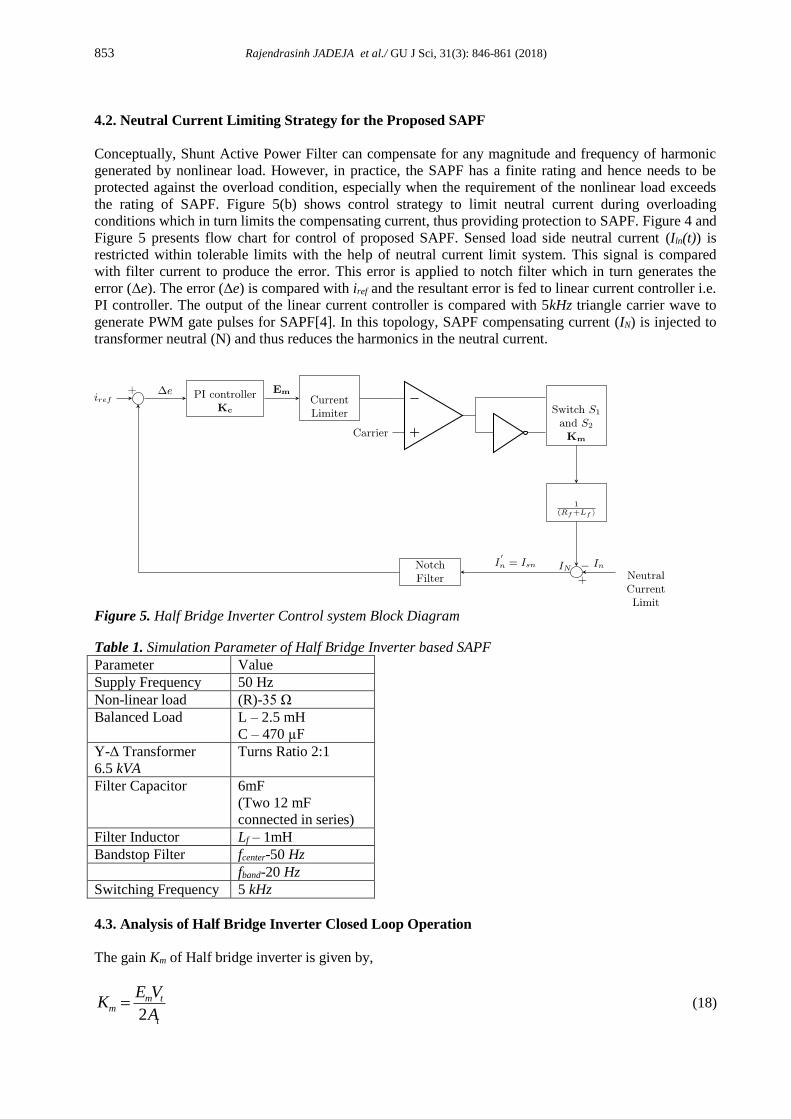
4.2. Neutral Current Limiting Strategy for the Proposed SAPF
Conceptually, Shunt Active Power Filter can compensate for any magnitude and frequency of harmonic
generated by nonlinear load. However, in practice, the SAPF has a finite rating and hence needs to be
protected against the overload condition, especially when the requirement of the nonlinear load exceeds
the rating of SAPF. Figure 5(b) shows control strategy to limit neutral current during overloading
conditions which in turn limits the compensating current, thus providing protection to SAPF. Figure 4 and
Figure 5 presents flow chart for control of proposed SAPF. Sensed load side neutral current (Iln(t)) is
restricted within tolerable limits with the help of neutral current limit system. This signal is compared
with filter current to produce the error. This error is applied to notch filter which in turn generates the
error (Δe). The error (Δe) is compared with iref and the resultant error is fed to linear current controller i.e.
PI controller. The output of the linear current controller is compared with 5kHz triangle carrier wave to
generate PWM gate pulses for SAPF[4]. In this topology, SAPF compensating current (IN) is injected to
transformer neutral (N) and thus reduces the harmonics in the neutral current.
Figure 5. Half Bridge Inverter Control system Block Diagram
Table 1. Simulation Parameter of Half Bridge Inverter based SAPF
Parameter Value
Supply Frequency 50 Hz
Non-linear load (R)-35 Ω
Balanced Load L – 2.5 mH
C – 470 µF
Y-Δ Transformer
6.5 kVA
Turns Ratio 2:1
Filter Capacitor 6mF
(Two 12 mF
connected in series)
Filter Inductor Lf – 1mH
Bandstop Filter fcenter-50 Hz
fband-20 Hz
Switching Frequency 5 kHz
4.3. Analysis of Half Bridge Inverter Closed Loop Operation
The gain Km of Half bridge inverter is given by,
2 m t
m
t
E VK
A (18)
854 Rajendrasinh JADEJA et al./ GU J Sci, 31(3): 846-861 (2018)
(a)
(b)
(c)
(d)
(e)
(f)
(g)
(h)
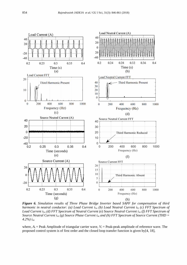
Figure 6. Simulation results of Three Phase Bridge Inverter based SAPF for compensation of third
harmonic in neutral conductor: (a) Load Current iLa (b) Load Neutral Current iln (c) FFT Spectrum of
Load Current iLa (d) FFT Spectrum of Neutral Current (e) Source Neutral Current isn (f) FFT Spectrum of
Source Neutral Current isn (g) Source Phase Current isa and (h) FFT Spectrum of Source Current (THD =
4.2%) isa
where, At = Peak Amplitude of triangular carrier wave, Vt = Peak-peak amplitude of reference wave. The
proposed control system is of first order and the closed loop transfer function is given by[4, 18],
855 Rajendrasinh JADEJA et al./ GU J Sci, 31(3): 846-861 (2018)
( )
( )
f fn N
N f f c m
R L sI I s
I s R L s K K (19)
The steady state error of closed loop transfer function is,
0
1( ) lim
1
sc m
f f
e sK K
R L s
(20)
The proportional constant Kp is defined as,
c mp
f
K KK
R (21)
Where Kp, Kc are PI controller constants, Km is inverter gain, Lf is inductor SAPF and Rf is resistance of
inductor.
5. SIMULATION RESULTS OF SHUNT ACTIVE POWER FILTER
5.1. Simulation Results of Three Phase Inverter Based SAPF
In order to compare the performance of presented SAPF with existing three phase three wire split
capacitor based SAPF, a model is simulated using MATLAB/ Simulink® software and where harmonic
contents are extracted with p−q theory and inverter is controlled using a linear current controller for
single phase nonlinear load. System parameters considered for simulation studies are mentioned in Table
1. The simulation results for the topology under balanced loading condition are shown in Figure 6. Load
current for all the phases, consisting of harmonics injected due to nonlinear load is shown in Figure 6.
FFT of the nonlinear load current is presented in Figure 6(b).
The presence of third harmonics, as well as other odd harmonics, is evident from the results. These
harmonics are injected in the source current and also causes issues of neutral currents as shown in Figure
6(c).
This SAPF compensates the neutral current harmonics and as a result, third harmonics other odd
harmonics are eliminated from the source current as shown in Figure 6(e). Neutral current without and
with compensation is shown in Figure 6(c) and Figure 6(d) respectively.
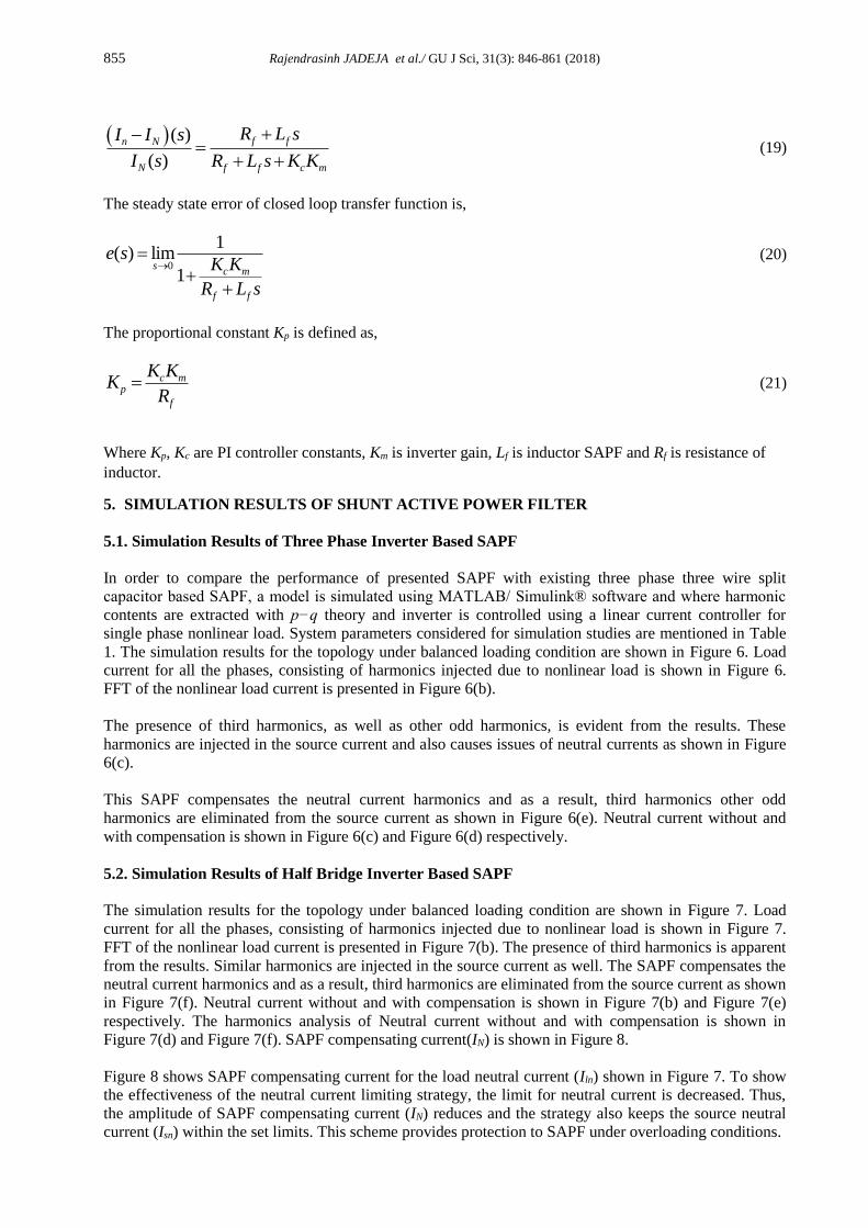
5.2. Simulation Results of Half Bridge Inverter Based SAPF
The simulation results for the topology under balanced loading condition are shown in Figure 7. Load
current for all the phases, consisting of harmonics injected due to nonlinear load is shown in Figure 7.
FFT of the nonlinear load current is presented in Figure 7(b). The presence of third harmonics is apparent
from the results. Similar harmonics are injected in the source current as well. The SAPF compensates the
neutral current harmonics and as a result, third harmonics are eliminated from the source current as shown
in Figure 7(f). Neutral current without and with compensation is shown in Figure 7(b) and Figure 7(e)
respectively. The harmonics analysis of Neutral current without and with compensation is shown in
Figure 7(d) and Figure 7(f). SAPF compensating current(IN) is shown in Figure 8.
Figure 8 shows SAPF compensating current for the load neutral current (Iln) shown in Figure 7. To show
the effectiveness of the neutral current limiting strategy, the limit for neutral current is decreased. Thus,
the amplitude of SAPF compensating current (IN) reduces and the strategy also keeps the source neutral
current (Isn) within the set limits. This scheme provides protection to SAPF under overloading conditions.
856 Rajendrasinh JADEJA et al./ GU J Sci, 31(3): 846-861 (2018)
(a)
(b)
(c)
(d)
(e)
(f)
(g)
(h)
Figure 7. Simulations results of Half bridge inverter based SAPF for third harmonic elimination in
neutral conductor : (a) Load Current iLa (b) Load Neutral Current iln (c) FFT Spectrum of Load Current
iLa (d) FFT Spectrum of Neutral Current (e) Source Neutral Current isn (f) FFT Spectrum of Source
Neutral Current isn (g) Source Phase Current isa and (h) FFT Spectrum of Source Current (THD =
36.6%) isa
The comparison of performance of both topology and strategy is given in Figure 9. In addition to this, the
performance of half bridge inverter based SAPF is tabulated in Table 2 under weak and strong grid
conditions. It is worth noting that under weak grid as well as strong grid conditions, the compensation
capabilities remain unaffected. The increased THD of source current after compensation is due to the fact
that nearest harmonics i.e. 5th and 7th remain unaffected. The magnitude of nearest harmonic has increased
in strong grid condition. Hence, it can be said that presented topology is a versatile solution under both
grid conditions.
0.2 0.24 0.28 0.32 0.36 0.4
Time (s)
0
-20
-40
20
40
Load Current (A)
0.2 0.24 0.28 0.32 0.36 0.4
Time (s)
0
-20
-40
20
40
Load Neutral Current (A)
0 200 400 600 800 1000
Frequency (Hz)
0
5
10
15
20
Load Current FFT (A)
0 200 400 600 800 1000
Frequency (Hz)
0
10
20
30
40
Load Neutral Current (A)
0.2 0.24 0.28 0.32 0.36 0.4
Time (s)
0
-20
-40
20
40
Source Neutral Current (A)
0 200 400 600 800 1000Frequency (Hz)
0
10
20
30
40Source Neutral Current (A)
0.2 0.24 0.28 0.32 0.36 0.4
Time (s)
0
-20
-40
20
40
Source Phase Current (A)
0 200 400 600 800 1000Frequency (Hz)
0
5
10
15
20
Source Phase Current (A)
Third Harmonic
Present Third Harmonic
Present
Third Harmonic Reduced
Third harmonic absent
857 Rajendrasinh JADEJA et al./ GU J Sci, 31(3): 846-861 (2018)
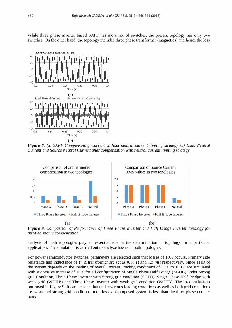
While three phase inverter based SAPF has more no. of switches, the present topology has only two
switches. On the other hand, the topology includes three phase transformer (magnetics) and hence the loss
(a)
(b)
Figure 8. (a) SAPF Compensating Current without neutral current limiting strategy (b) Load Neutral
Current and Source Neutral Current after compensation with neutral current limiting strategy
(a)
(b)
Figure 9. Comparison of Performance of Three Phase Inverter and Half Bridge Inverter topology for
third harmonic compensation
analysis of both topologies play an essential role in the determination of topology for a particular
application. The simulation is carried out to analyze losses in both topologies.
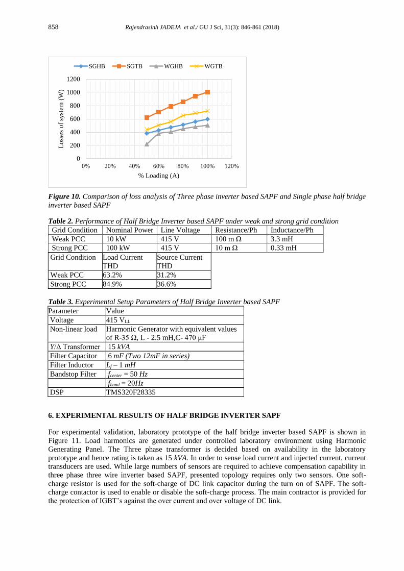
For power semiconductor switches, parameters are selected such that losses of 10% occurs. Primary side
resistance and inductance of Y−Δ transformer are set as 0.16 Ω and 1.5 mH respectively. Since THD of
the system depends on the loading of overall system, loading conditions of 50% to 100% are simulated
with successive increase of 10% for all configuration of Single Phase Half Bridge (SGHB) under Strong
grid Condition, Three Phase Inverter with Strong grid condition (SGTB), Single Phase Half Bridge with
weak grid (WGHB) and Three Phase Inverter with weak grid condition (WGTB). The loss analysis is
portrayed in Figure 9. It can be seen that under various loading conditions as well as both grid conditions
i.e. weak and strong grid conditions, total losses of proposed system is less than the three phase counter
parts.
0.2 0.24 0.28 0.32 0.36 0.4
Time (s)
0
-20
-40
20
40
SAPF Compensating Current (A)
0.2 0.24 0.28 0.32 0.36 0.4
Time (s)
0
-20
-40
20
40
Load Neutral Current Source Neutral Current (A)
0
0,5
1
1,5
2
Phase A Phase B Phase C Neutral
Comparison of 3rd harmonic
compensation in two topologies
Three Phase Inverter Half Bridge Inverter
0
5
10
15
20
Phase A Phase B Phase C Neutral
Comparison of Source Current
RMS values in two topologies
Three Phase Inverter Half Bridge Inverter
858 Rajendrasinh JADEJA et al./ GU J Sci, 31(3): 846-861 (2018)
Figure 10. Comparison of loss analysis of Three phase inverter based SAPF and Single phase half bridge
inverter based SAPF
Table 2. Performance of Half Bridge Inverter based SAPF under weak and strong grid condition
Grid Condition Nominal Power Line Voltage Resistance/Ph Inductance/Ph
Weak PCC 10 kW 415 V 100 m Ω 3.3 mH
Strong PCC 100 kW 415 V 10 m Ω 0.33 mH
Grid Condition Load Current
THD
Source Current
THD
Weak PCC 63.2% 31.2%
Strong PCC 84.9% 36.6%
Table 3. Experimental Setup Parameters of Half Bridge Inverter based SAPF
Parameter Value
Voltage 415 VLL
Non-linear load Harmonic Generator with equivalent values
of R-35 Ω, L - 2.5 mH,C- 470 μF
Y/Δ Transformer 15 kVA
Filter Capacitor 6 mF (Two 12mF in series)
Filter Inductor Lf – 1 mH
Bandstop Filter fcenter = 50 Hz
fband = 20Hz
DSP TMS320F28335
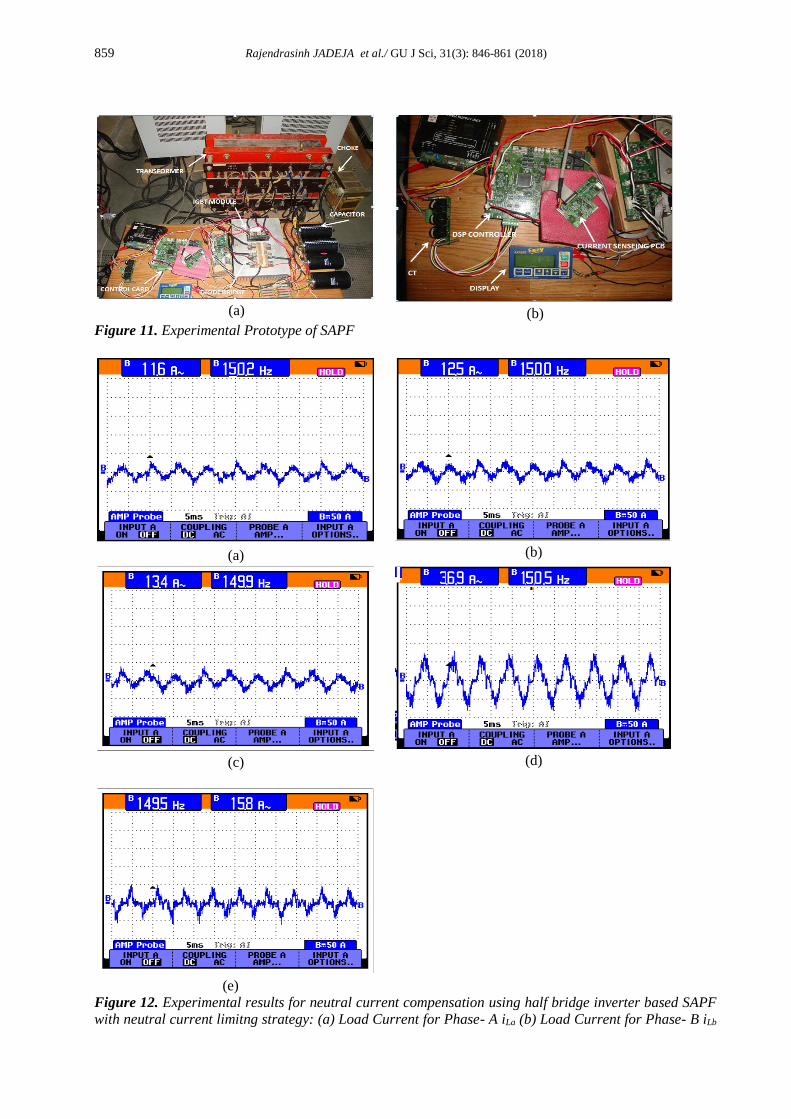
6. EXPERIMENTAL RESULTS OF HALF BRIDGE INVERTER SAPF
For experimental validation, laboratory prototype of the half bridge inverter based SAPF is shown in
Figure 11. Load harmonics are generated under controlled laboratory environment using Harmonic
Generating Panel. The Three phase transformer is decided based on availability in the laboratory
prototype and hence rating is taken as 15 kVA. In order to sense load current and injected current, current
transducers are used. While large numbers of sensors are required to achieve compensation capability in
three phase three wire inverter based SAPF, presented topology requires only two sensors. One soft-
charge resistor is used for the soft-charge of DC link capacitor during the turn on of SAPF. The soft-
charge contactor is used to enable or disable the soft-charge process. The main contractor is provided for
the protection of IGBT’s against the over current and over voltage of DC link.
0
200
400
600
800
1000
1200
0% 20% 40% 60% 80% 100% 120%
Lo
sses
of
syst
em (
W)
% Loading (A)
SGHB SGTB WGHB WGTB
859 Rajendrasinh JADEJA et al./ GU J Sci, 31(3): 846-861 (2018)
(a)
(b)
Figure 11. Experimental Prototype of SAPF
(a)
(b)
(c)
(d)
(e)
Figure 12. Experimental results for neutral current compensation using half bridge inverter based SAPF
with neutral current limitng strategy: (a) Load Current for Phase- A iLa (b) Load Current for Phase- B iLb
860 Rajendrasinh JADEJA et al./ GU J Sci, 31(3): 846-861 (2018)
(c) Load Current for Phase- C iLc (d) Load Neutral Current iLn (e) Source Current with limiting strategy
[X-axis: 5 ms/div, Y-axis: 50 A/div]
For control of SAPF, a 32-bit floating point processor DSP TMS320F28355 is programmed using C
Programming. Control card of DSP takes various feedback signals like load currents, filter currents,
supply voltages, and DC link voltage through a 12-bit Analog to Digital Converter. The event manager
module of DSP generates gate pulses for SAPF with the help of ePWM submodules. A separate
subroutine takes care of neutral current limiting strategy and entire control algorithm is operated at a
sample time of 100 μs. Load currents of all the phases Ila,Ilb & Ilc are shown in Figure 12, Figure 12(a),
Figure 12(b) and Figure 12(c), respectively. Load neutral current (Iln) is presented in Figure 12(d), while
Source side neutral current (IN) is shown in Figure 12(e). In this case, the limit for the compensating
current is considered as 16 Amp. Effective operation of the SAPF is illustrated from the experimental
results.
7. CONCLUSION
A star-delta transformer and half-bridge inverter based SAPF is implemented for elimination zero
sequence component in neutral due to triplens and thereby eliminating triplen from the source side. The
topology of SAPF utilizes less number of switches and thereby reducing SAPF rating as well as switching
losses. SAPF connected with supply through the star-delta transformer is used to mitigate neutral current
harmonics thereby eliminating third harmonics from the system. Unique control strategy for protecting
the SAPF in the case of overloading conditions is also presented. The behavior of the proposed SAPF is
compared with the performance of conventional three phase SAPF through simulation analysis. A DSP
based laboratory prototype of proposed SAPF is developed for validation. Experimental and simulation
results of the presented SAPF indicate that the solution works satisfactorily for mitigation of third
harmonic and neutral current.
CONFLICTS OF INTEREST
No conflict of interest was declared by the authors.
REFERENCES
[1] Dugan R. C., McGranaghan M. F., Wayne B.H., "Electrical power systems quality", TATA Mc-Graw
Hill India, (1996).
[2] Gruzs T. M., "A survey of neutral currents in three-phase computer power systems", IEEE
Transactions on Industry Applications, 26(4), 719-725, (1990).
[3] -, "Effects of Nonlinear Loads on Electrical Circuits and Equipment: Summary of a Symposium",
National Academy Press, (1991).
[4] Pitel I. J., Enjeti P., "Active harmonic power filter apparatus and method," 1996.
[5] Singh B., Al-Haddad K., Chandra A., "A review of active filters for power quality improvement",
IEEE Transactions on Industrial Electronics, 46(5), 960-971, (1999).
[6] Akagi H., "Instantaneous power theory and application to power conditioning", John Wiley & Sons,
(2004).
[7] Trivedi T. A., Jadeja R., Bhatt P., "A Review on Direct Power Control for Applications to Grid
Connected PWM Converters", Engineering, Technology & Applied Science Research, 5(4), 841-
849, (2015).
861 Rajendrasinh JADEJA et al./ GU J Sci, 31(3): 846-861 (2018)
[8] Sreenivasarao D., Agarwal P., Das B., "Neutral current compensation in three-phase, four-wire
systems: A review", Electric Power Systems Research, 86, 170-180, (2012).
[9] Saribulut L., Ahmet T., Meral M. E., Tumay M., "Active power filter: review of converter topologies
and control strategies", Gazi university journal of science, 24(2), 283-289, (2011).
[10]RodrÍguez P., Candela J. I., Luna A., Asiminoaei L., Teodorescu R., Blaabjerg F., "Current
Harmonics Cancellation in Three-Phase Four-Wire Systems by Using a Four-Branch Star Filtering
Topology", IEEE Transactions on Power Electronics, 24(8), 1939-1950, (2009).
[11]Bouzelata Y., Kurt E., Chenni R., Altın N., "Design and simulation of a unified power quality
conditioner fed by solar energy", International Journal of Hydrogen Energy, 40(44), 15267-15277,
(2015).
[12]Ucar M., Ozdemir E., "Control of a 3-phase 4-leg active power filter under non-ideal mains voltage
condition", Electric Power Systems Research, 78(1), 58-73, (2008).
[13]Kale M., Ozdemir E., "Harmonic and reactive power compensation with shunt active power filter
under non-ideal mains voltage", Electric Power Systems Research, 74(3), 363-370, (2005).
[14]Izhar M., Hadzer C. M., Syafrudin M., Taib S., Idris S., "An analysis and design of a star delta
transformer in series with active power filter for current harmonics reduction", PECon 2004.
Proceedings. National Power and Energy Conference, 94-98, (2004).
[15]Singh B., Jayaprakash P., Kothari D. P., "Magnetics for neutral current compensation in three-phase
four-wire distribution system", Joint International Conference on Power Electronics, Drives and
Energy Systems Power India, 1-7, (2010 ).
[16]Jayaprakash P., Singh B., Kothari D. P., "Digital Signal Processor Implementation of Isolated
Reduced-rating Voltage Source Converter Using a Zig-zag Transformer for Three-phase Four-wire
Distribution Static Compensator", Electric Power Components and Systems, 39(1), 15-30, (2011).
[17]Singh B., Jayaprakash P., Kothari D. P., "A T-Connected Transformer and Three-leg VSC Based
DSTATCOM for Power Quality Improvement", IEEE Transactions on Power Electronics, 23(6),
2710-2718, (2008).
[18]Quinn C. A., Mohan N., "Active filtering of harmonic currents in three-phase, four-wire systems with
three-phase and single-phase nonlinear loads", Applied Power Electronics Conference and
Exposition , Seventh Annual, 829-836, (1992).