Embed Size (px)
Citation preview

Nous sommes done conduits a 1 < /x < 2. Pour mesurer/x, nous avons trace la courbe
log10 s = f(loglQId)
On doit trouver la droite
Pour verifier, a posteriori, nos calculs, nous avons fait lasynthese de Id = f(ug)(a) en considerant comme etabli experimentalement que
s = f(Jd) etait de la forme eqn. 3(b) en supposant la validite de eqn. 1
(c) en calculant alors Id = f(ug) et en comparant aux resultatsexperimentaux; Idss et s0 sont obtenus par extrapolationde Id = f(ug) ets= f(ug), up par application de eqn. 2
Resultats: Us sont traduits par les courbes des Figs. la et b,relevees au moyen de l'appareillage Fig. \c.
(i) Pour les U1285 utilises, l'accord est tres satisfaisantsinon excellent et conduit a
l - 6 8 < / x < 1-72(ii) Pour les 2N3368, il est necessaire de prevoir un radia-
teur thermique du fait du fort courant drain et de la fortepente. Nous avons utilise une plaque de cuivre epaisse de5-10 mm et d'environ 10 cm2 de surface. Nous avonsobtenu
1 - 5 3 < J L C < 1-58
Precision des mesures: Les principales sources d'erreur sontl'extrapolation pour la determination de ,y0 et, a un titremoindre, la meme operation pour la determination de Idss.Ceci signifie que e'est sur up que Ton a la plus mauvaise preci-sion. D'autre part la precision sur le calcul de Id est fonctionde ug et est d'autant meilleure que ug est plus faible.
Pour les mesures que nous avons effectuees et pour laverification des resultats nous pouvons, au pire, compter surune precision de 5 %.
Conclusion: La methode proposee pour la mesure des pentesoffre des avantages certains:
(a) facilite d'utilisation et de mise au point(b) precision qui est celle des methodes de zero
Quant a l'etude faite sur les f.e.t, il est certain, contrairementa ce que pense Sevin,2 que l'exposant intervenant dans larelation Id = f(ug) peut prendre, selon le dopage du canal,des valeurs inferieures a 2.
R. GENINP. BREZEL
31st July 1967
Faculte des Sciences de BrestUniversite de RennesAvenue Le Gorgeu, 28 N Brest, France
References1 KRAKAUER, s.: 'Electrometer triode follower', Rev. Sci. lustrum.,
1953, 24, pp. 496-5002 SEVIN, L. J., JUN. : 'Field effect transistors' (Texas Instruments I n c -
McGraw-Hill, 1965), pp. 4-243 LAMMING, J. s.: 'Comparison of three simple field-effect-transistor
models', Electronics Letters, 1966, 2, pp. 147-148
LAUNCHING A SURFACE WAVE OVERTHE EARTH
It is pointed out that a recent proposal to launch a surfacewave over a homogeneous surface has some fundamentaldrawbacks. However, it is possible that such a device may beuseful as a launcher for trapped surface waves over a highlyinductive surface.
In an interesting letter,A Barlow proposes to launch a surfacewave over the Earth by an ingenious ferrite-loaded horndevice. If, indeed, the Earth would support a Zenneck-typesurface wave, such a device could have a real merit. Theinhomogeneous plane wave envisaged by Barlow is stated tohave a vertical-field-decay coefficient of 2-03 x 10~3 withthe field falling to 1/e of its surface value at a height of 492 m.Although such a wave may be supported by a dielectric- orferrite-loaded surface, it would not be excited over a homo-geneous conducting surface by any physical source.6
In order to discuss the question, we consider a uniform flatsurface which exhibits a surface impedance Zs. Choosing aCartesian-coordinate system xyz, we imagine that a verticallypolarised wave travels in the x direction and has no variationin the y direction. The Earth's surface is z = 0 and the zaxisis directed vertically upwards. It is a simple exercise to showthat the magnetic field has only a y component, which wedesignate H(x, z). In order to satisfy the surface-impedanceboundary conditions at z = 0, the field, for a time factorexp (ja)t), must have the form
H(x,z) = A ) exp {-jk(l - *} . (1)
where A = Zj 120TT is the normalised surface impedance andk = (€0/x0)
1/2o> is the free-space wavenumber.Now, it is true that the field decays with height when A has
a finite real part (i.e. for Xs > 0, where Zs = Rs + jXs).However, the important factor is that a surface wave of thetype exhibited by eqn. 1 is not excited by a source unlessRe (1 — A2)1/2 > 1. In other words, if a surface wave isexcited, it is a slow wave, in the sense that its phase velocityis less than that of c. This condition may be written in theequivalent form
arg {sin (̂ arc sin A)} > IT IA (2)
or, if |A|2 <̂ 1, this condition is arg A > TT/4. The restrictiongiven by eqn. 2 is also found from an asymptotic evaluationof the integral representation for a source-excited structure.2
For a homogeneous surface, the phase angle of A can neverbe greater than TT/4.
It is worth pointing out that a Zenneck wave, which ischaracterised by the condition Re (1 — A2)1/2 < 1, is a fastwave. Thus, it violates Barlow's and Brown's concept that asurface wave on a uniform structure does not radiate.c
It is doubtful if the horn device described by Barlow isany more effective, in launching ground waves over a homo-geneous surface, than a vertical-mast aerial of the samephysical height. In either case, the excited field is proportionalto the integral
r-Ga{z)G(z)dz (3)
where h0 is the height of the aperture, Ga(z) is the aperturedistribution and G(z) is the height-gain function for theradiated groundwave.2 The latter is given approximatelyby G{z) ~ 1 + ikkz, which has a fundamentally differentcharacter from Ga(z).
It is possible that, under certain conditions of Earthstratification, the surface impedance will be sufficientlyinductive for a slow trapped surface wave to be excited.B Itmay have a height-gain function not entirely unlike theexponential form at the exit aperture of Barlow's horn device.It seems that, if any attempts are made to construct such horridevices, they should be operated over highly inductivesurfaces such as ice-covered sea.
J. R. WAIT 4th August 1967
396
Environmental Science Services AdministrationBoulder, Colo. 80302, USA
ELECTRONICS LETTERS September 1967 Vol. 3 No. 9
ReferencesA BARLOW, H. M. : 'Launching a surface wave over the earth', Electronics
Letters, 1967, 3, pp. 304-305B WAIT, j . R.: 'Electromagnetic waves in stratified media' (Pergamon
Press, 1962), chap. 2c BARLOW, H. M., and BROWN, J.: 'Radio surface waves' (Clarendon
Press, 1962)
Wait postulates that a wave of the kind under considerationmust necessarily have a phase velocity along the interfaceless than that in free space. As far as I can see, this limitationdoes not derive from any boundary conditions that have to besatisfied in support of the wave, and relates exclusively toconsiderations of excitation by the source.
The problem therefore resolves itself into that of providinga suitable launching aerial putting as much of the radiatedenergy as possible into the required form.
As Wait has said, the Zenneck wave is a fast one whenpropagated over a smooth surface which is predominantlyconducting. In principle, there seems no reason to precludesuch a wave from realisation in practice. In any case, thenatural surface roughness of the earth would no doubt addthe very small reactance required to convert the wave to aslow one.
It is also relevant to recall that experiments0 on the axialcylindrical surface wave, which transforms to the Zenneckwave for a large-diameter guide, have shown without doubtthat it can exist as a fast wave as well as a slow one.
In denning a pure surface wave as one that propagatesalong an interface without radiation,E it seems undesirable,and indeed unnecessary, additionally to impose the condition,as applied by Wait, that the wave must be slow.
At the supporting surface, the resistive and reactivecomponents of the impedance presented to the wave tend tooperate in opposite senses, as far as the phase velocity alongthe interface is concerned, the former increasing it by addingtd the forward tilt of the wavefront, and the latter reducing itby augmenting the energy storage. Thus no great signi-ficance is necessarily attached to the fast-wave behaviour ofthe Zenneck wave over a smooth conducting flat surface,because this arises simply from the slight excess of resistanceover reactance in that case.
H. M. BARLOW 14th August 1967
Department of Electrical EngineeringUniversity College LondonTor ring ton Place, London WC1, England
ReferencesD BARLOW, H. M., and KARBOWIAK, A. E. : 'An experimental investigation
of axial cylindrical surface waves supported by capacitive surfaces',Proc. IEE, 1955, 102B, (5), pp. 313-322
E BARLOW, H. M., and BROWN, j . : 'Radio surface waves' (ClarendonPress, 1962)
VARIABLE EQUALISERSIt is shown that the well known Bode variable equaliser isone member of a family of four networks having broadlysimilar properties. Two of these members, one of whichappears to be new, have particular advantages for meetingrequirements that are specified in the time domain.
A requirement often arises for a variable equaliser in which thescale, and sometimes the sign, of the loss in a loss/frequencycharacteristic can be varied without seriously affecting itsshape. Networks which enable this to be done, under thecontrol of a single variable resistor, were first described byBode,1 and subsequent publications2'3 have described, inmore detail, suitable methods of design. This letter comparesthe Bode network with three other networks having similarconfigurations, and considers not only their frequencycharacteristics, but also their time responses.
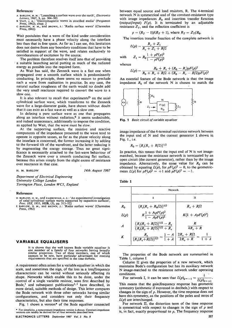
Fig. 1 shows a version* of the Bode equaliser connected
* For simplicity, a nonconstant-impedance version is shown. Constant-impedanceversions can readily be derived for all four networks described here
ELECTRONICS LETTERS September 1967 Vol. 3 No. 9
between equal source and load resistors, R. The 4-terminalnetwork N is symmetrical and of the constant-resistance typewith image impedances Ro and insertion transfer function(output/input) F(p). It is terminated by an adjustableresistance ZT, and the reflection coefficient is
p = (RT- 1)/(RT + 1), where RT = ZT/RQ.
The insertion transfer function of the complete network is
with Zx =
{+ R/2
PF(p)2
- PF{p)2
whence(Ro ~
Ro + Rs + R/2 + (RQ — Rs - R/2)pF(j>)2
An essential feature of the Bode network is that the imageimpedance Ro of the network N is chosen to match the
Fig. 1 Basic circuit of variable equaliser
image impedance of the 4-terminal resistance network betweenthe input end of N and the current generator I shown inFig. 1., i.e.
Ro = {RS(RS + RIDY'2
In practice, this means that the input end of N is not image-matched, because the resistance network is terminated by anopen circuit (the current generator), rather than by the imageimpedance. Alternatively, the same value for RQ can beobtained by equating L{p), for pF(j?)2 = 0, to the geometric-mean L(p) for pF(j))2 = +1 and pF(p)2 = - 1 .
Table 1
A
v-
I
{RS(RS + BJDYI*
1 +APF(p)2
A l -ApF(p)2
{RS(RS + R/2)y'2 -{RS(RS + R/2)yi2 4
Rs J{iJ/iJ.+i?/!)}1/2 1
Network
RsRs
- A+ A
h
2RS
2R
II
Rs + RI2
:{i + APF(J>)2}
R4RS + R
+ R\2 1S + R 1 + A
The properties of the Bode network are summarised inTable 1, column I
Column II gives the properties of a new network, whichmaintains Bode's configuration but has its auxiliary networkN image-matched to the resistance network under operatingconditions. j •
For network I, it can be seen that L(/7)p=-i =
+This means that the gain/frequency response has geometricsymmetry (arithmetic if expressed in decibels,) with respect tochanges in the sign of p. However, the time response does nothave this symmetry, as the positions of the poles and zeros ofL(p) are interchanged.
For network II, the distortion term of the time responseis symmetrical with respect to changes in the sign of p andis, in fact, exactly proportional to p. The frequency response
397