Embed Size (px)
Citation preview
Vol. 11, No. 1/January 1994/J. Opt. Soc. Am. A 197
Light scattering from multilayer optics.I. Tools of investigation
C. Amra
Laboratoire d'Optique des Surfaces et des Couches Minces, Unite de Recherche (1120) Associ6e au Centre Nationalde la Recherche Scientifique, Ecole Nationale Supgrieure de Physique de Marseille,
Domaine Universitaire de St. Jer6me, 13397 Marseille Cedex 20, France
Received December 14, 1992; revised manuscript received June 17, 1993; accepted June 17, 1993
We emphasize the role of correlated isotropy in the study of microroughness in high-quality optical coatings.First, cross correlation between surfaces and cross coherence between scattering sources are discussed andcompared. An isotropy degree of roughness is then introduced as a quantitative value to describe the angulardisorder of a surface connected with the polar dependence of scattering. We show how the frequency varia-tions of this isotropy degree allow one to solve the inverse problem and obtain a unique solution for the scatter-ing parameters that describe structural irregularities of the stacks. Light scattering can also be used to detectan oblique growth of the materials in thin-film form. Finally, we study the sensitivity of the investigationmethod to the stack parameters.
Key words: scattering, roughness, irregularity spectrum, cross correlation, cross coherence, isotropy degree,inverse problem, replication, microstructure, thin films, multilayers, oblique deposition
1. INTRODUCTION
Although many projects 4 have been devoted to the studyof light scattering in optical multilayers, there is still astrong demand to reduce this loss of light, and this is acritical point for current applications. Certainly the best-known effect is the retroscattering from the mirrors in alaser gyro system, but the problem is also significant forhigh-quality antireflection coatings and narrow-band fil-ters. In other words, scattering is a critical issue as longas an energy balance with an accuracy better than 10-3 isrequired.
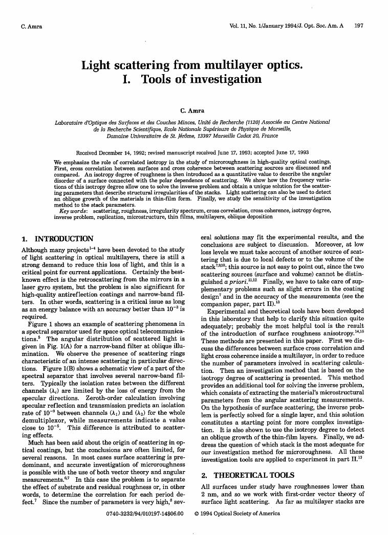
Figure 1 shows an example of scattering phenomena ina spectral separator used for space optical telecommunica-tions.5 The angular distribution of scattered light isgiven in Fig. 1(A) for a narrow-band filter at oblique illu-mination. We observe the presence of scattering ringscharacteristic of an intense scattering in particular direc-tions. Figure 1(B) shows a schematic view of a part of thespectral separator that involves several narrow-band fil-ters. Typically the isolation rates between the differentchannels (i) are limited by the loss of energy from thespecular directions. Zeroth-order calculation involvingspecular reflection and transmission predicts an isolationrate of 10-9 between channels (Al) and (A2) for the wholedemultiplexor, while measurements indicate a valueclose to 10-5. This difference is attributed to scatter-ing effects.
Much has been said about the origin of scattering in op-tical coatings, but the conclusions are often limited, forseveral reasons. In most cases surface scattering is pre-dominant, and accurate investigation of microroughnessis possible with the use of both vector theory and angularmeasurements.6'7 In this case the problem is to separatethe effect of substrate and residual roughness or, in otherwords, to determine the correlation for each period de-fect.7 Since the number of parameters is very high,8 sev-
eral solutions may fit the experimental results, and theconclusions are subject to discussion. Moreover, at lowloss levels we must take account of another source of scat-tering that is due to local defects or to the volume of thestack7'910; this source is not easy to point out, since the twoscattering sources (surface and volume) cannot be distin-guished a priori.11'12 Finally, we have to take care of sup-plementary problems such as slight errors in the coatingdesign7 and in the accuracy of the measurements (see thecompanion paper, part II).3
Experimental and theoretical tools have been developedin this laboratory that help to clarify this situation quiteadequately; probably the most helpful tool is the resultof the introduction of surface roughness anisotropy.4 ,5
These methods are presented in this paper. First we dis-cuss the differences between surface cross correlation andlight cross coherence inside a multilayer, in order to reducethe number of parameters involved in scattering calcula-tion. Then an investigation method that is based on theisotropy degree of scattering is presented. This methodprovides an additional tool for solving the inverse problem,which consists of extracting the material's microstructuralparameters from the angular scattering measurements.On the hypothesis of surface scattering, the inverse prob-lem is perfectly solved for a single layer, and this solutionconstitutes a starting point for more complex investiga-tion. It is also shown to use the isotropy degree to detectan oblique growth of the thin-film layers. Finally, we ad-dress the question of which stack is the most adequate forour investigation method for microroughness. All theseinvestigation tools are applied to experiment in part JJ.3
2. THEORETICAL TOOLS
All surfaces under study have roughnesses lower than2 nm, and so we work with first-order vector theory ofsurface light scattering. As far as multilayer stacks are
0740-3232/94/010197-14$06.00 © 1994 Optical Society of America
C. Amra
198 J. Opt. Soc. Am. A/Vol. 11, No. 1/January 1994
In these conditions the scattered intensity from ap-layer stack can be written as
pI(0, ) = Ci (0, 0)lYij(0 0)X
i'j
where Cij = CiCj are optical factors and Yij are cross-correlation spectra between interface profiles. 0 and kcharacterize scattering directions ( from the sample nor-mal and 4 from the polar angle). I(0, *) is often called theBRDF.cos 0 function,20 where the bidirectional reflectancedistribution function (BRDF) is equivalent to a luminance.
A. Incidence, Wavelength, and PolarizationSuppose that a family of parameters permits one to fit theangular loss of energy for particular illumination condi-tions. For verification of the validity or uniqueness ofthe solution, it is necessary to vary the incidence, thewavelength, or the polarization and compare the experi-ment with the prediction given by the same set of parame-ters. For this it is necessary to be familiar with thesethree effects.
F4 0 F2F1
Fig. 1. (A) Three-dimensional scattering distribution from anarrow-band filter at oblique illumination (i = 30°). The designis HL HL H 6L H LH LH. The illumination wavelength is equalto the design wavelength Ao. 1, R and T characterize the specu-lar directions of the incident, reflected, and transmitted flux.BRDF. cos 0 is the flux scattered per unit of surface and solidangle, normalized to the incident flux. 0 and q characterize ascattering direction ( from the sample normal, 0 from the polarangle). Note the presence of scattering rings characteristic ofthe Fabry-Perot design. (B) Scattering phenomena in an opticaldemultiplexer. Ao, Al, and A2 are the wavelengths to be sepa-rated. F indicate optical filters, most of which are multiple-cavity Fabry-Perot filters. For each filter the angular scatteringis plotted for the illumination wavelengths Ao (dotted curves), Al(dashed curves), and A2 (solid curves). The isolation rates arealtered because the scattered light does not follow the speculardirections given by Snell's laws. This effect is amplified whenwe bring the optical elements closer to one another to obtain acompact system, which decreases the demultiplexer performances.
concerned, two theories16 "7 have an essential place, andwe know that they lead to identical results.' 8 However,the validity of the theory must be kept in mind:
* The surface roughness is much less than the inci-dent wavelength (the wavelength under study is 632.8 nm).
* The slope of surface defects is much less than unity(this slope is given by the ratio of roughness to correlationlength; experimental results confirm this condition').
* The surfaces are free of local defects (dust, pits,scratches, etc.); this condition can be checked under opti-cal microscope observations.
1. PolarizationFor nonpolarized illumination, the optical terms must bewritten as
CN = (Cgy + C + CPS + C,>)
where the SP indicates P-polarized scattered light that isdue to an S-polarized incident beam. At normal illumina-tion (i = 0), we obtain
CjS = cos2 0 cos2 OCjS(0),
CP = coS2 OC~j(0),
CiPS
is
= tan2 ,is
In these conditions, and provided that surfaces andvolumes are isotropic in the stack ['yj(0, 4) = yjj(0)], someconclusions are immediate:
* IS and Isp can be deduced from I~s and Ipp, respec-tively, by a wr/2 rotation in the polar plane 4 (notice theabsence of cross-polarized light in the plane 0 = 0).
* If (N) is relative to nonpolarized incident or scat-tered light, then INS, INP, and INN are of revolution aroundthe sample normal. Moreover, INN can be written as
INN = INS + iNP =1 (ISS + IPS + ISP + IPP)2
=> INN(0) = 1 [Ss( 0,0) + IPP(0,0)].2
* If D indicates total scattering losses (integrated inwhole space), we obtain
Dss = Dps, DPP = Dsp => DNS = Dss, DNP = DPP
=> DNN = 1 (2DSS + 2D"'1) = DSS + DP± .2
* Finally, one can easily verify that, for a circular po-larized incident beam, scattering is zero in the plane10= V/4.
(A)1
T
(1)
C. Amra
Vol. 11, No. 1/January 1994/J. Opt. Soc. Am. A 199
BRDF.cosOe,
0 Xi = 400 nm
Xo =633 nm
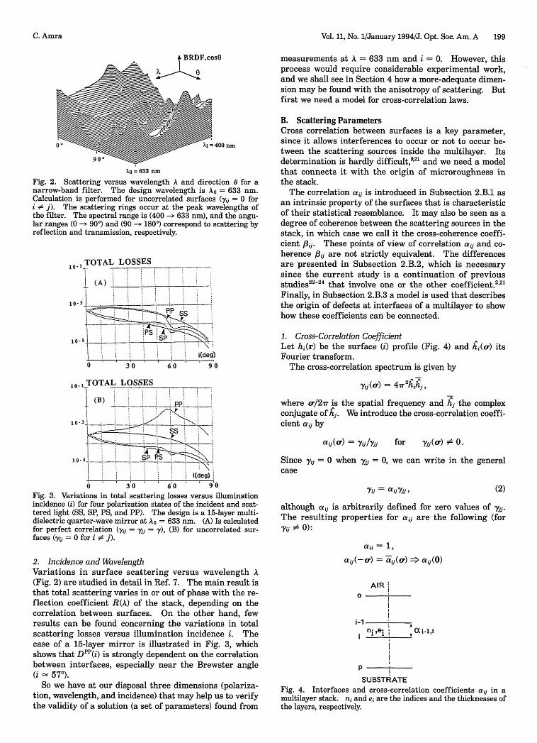
Fig. 2. Scattering versus wavelength A and direction 0 for anarrow-band filter. The design wavelength is A = 633 nm.Calculation is performed for uncorrelated surfaces ( = 0 fori #A j). The scattering rings occur at the peak wavelengths ofthe filter. The spectral range is (400 -> 633 nm), and the angu-lar ranges (0 -> 90') and (90 -- 180°) correspond to scattering byreflection and transmission, respectively.
- TOTAl
(A)
, .3
L LOSSES
* _ _ _ _ P ~ ~ ~~~~~~~~~~~~~~~~~~~~........
Ssi(deg)
0 30 60 90
(B)0 13 a V I
_ ___ ____ _____
!(deg)0 3o0 630 90
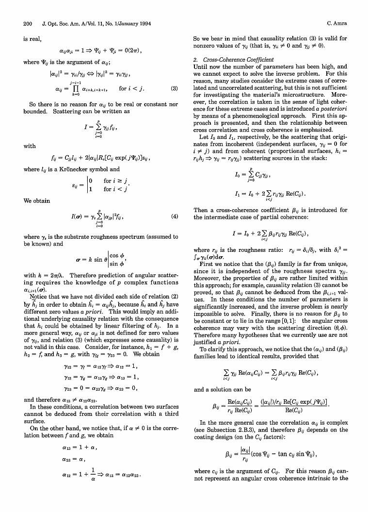
Fig. 3. Variations in total scattering losses versus illuminationincidence (i) for four polarization states of the incident and scat-tered light (SS, SP, PS, and PP). The design is a 15-layer multi-dielectric quarter-wave mirror at AO = 633 nm. (A) Is calculatedfor perfect correlation (yij = yj= ), (B) for uncorrelated sur-faces (Yi = 0 for i ;.
2. Incidence and WavelengthVariations in surface scattering versus wavelength A(Fig. 2) are studied in detail in Ref. 7. The main result isthat total scattering varies in or out of phase with the re-flection coefficient R(A) of the stack, depending on thecorrelation between surfaces. On the other hand, fewresults can be found concerning the variations in totalscattering losses versus illumination incidence i. Thecase of a 15-layer mirror is illustrated in Fig. 3, whichshows that DP"(i) is strongly dependent on the correlationbetween interfaces, especially near the Brewster angle(i 570).
So we have at our disposal three dimensions (polariza-tion, wavelength, and incidence) that may help us to verifythe validity of a solution (a set of parameters) found from
measurements at A = 633 nm and i = 0. However, thisprocess would require considerable experimental work,and we shall see in Section 4 how a more-adequate dimen-sion may be found with the anisotropy of scattering. Butfirst we need a model for cross-correlation laws.
B. Scattering ParametersCross correlation between surfaces is a key parameter,since it allows interferences to occur or not to occur be-tween the scattering sources inside the multilayer. Itsdetermination is hardly difficult,9 2 and we need a modelthat connects it with the origin of microroughness inthe stack.
The correlation aij is introduced in Subsection 2.B.1 asan intrinsic property of the surfaces that is characteristicof their statistical resemblance. It may also be seen as adegree of coherence between the scattering sources in thestack, in which case we call it the cross-coherence coeffi-cient f3ij. These points of view of correlation aij and co-herence 3ij are not strictly equivalent. The differencesare presented in Subsection 2.B.2, which is necessarysince the current study is a continuation of previousstudies 2 2
-24 that involve one or the other coefficient. 2 21
Finally, in Subsection 2.B.3 a model is used that describesthe origin of defects at interfaces of a multilayer to showhow these coefficients can be connected.
1. Cross-Correlation CoefficientLet hi(r) be the surface (i) profile (Fig. 4) and hi(o) itsFourier transform.
The cross-correlation spectrum is given by
Yu (a) = 4 hj,
where cr/2ir is the spatial frequency and hj the complexconjugate of hj. We introduce the cross-correlation coeffi-cient aij by
a (r) = yi/yj for y 1(or) =# 0.
Since y = 0 when yjj = 0, we can write in the generalcase
y, = a yi, (2)
although aij is arbitrarily defined for zero values of yi.The resulting properties for aij are the following (foryj # 0):
aii= 1,a i(-a) = cij(a) > aij(0)
AIR!0
P;
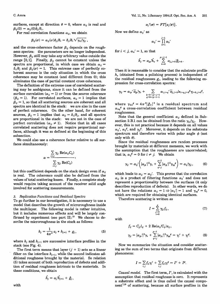
SUBSTRATEFig. 4. Interfaces and cross-correlation coefficients aij in amultilayer stack. n and ei are the indices and the thicknesses ofthe layers, respectively.
C. Amra
. V -
200 J. Opt. Soc. Am. A/Vol. 11, No. 1/January 1994
is real,
aijaji = 1 X 'tij + Tji = 0(27r),
where Tij is the argument of aij;
laid2 = ii/Vjj X IyiI2 = yiiy>,j-i-'
aij = H ai+k,i+k+l, for i < j. (3)k-0
So there is no reason for aij to be real or constant norbounded. Scattering can be written as
pI = Xyyg>
j=0i-o
with
fi = Cjjlij + 2aiJlRe[Cij exp j)]sij,
where lij is a Kronecker symbol and
0 fori jj 1 for i < j
We obtain
I(a) = js pl2fu, (4)j=0i
where y is the substrate roughness spectrum (assumed tobe known) and
r= k sin0 Cos 'sin 4
with k = 2/A. Therefore prediction of angular scatter-ing requires the knowledge of p complex functionsai,i+(or).
Notice that we have not divided each side of relation (2)by hj in order to obtain hi = aijhj, because hi and hj havedifferent zero values a priori. This would imply an addi-tional underlying causality relation with the consequencethat hi could be obtained by linear filtering of hj. In amore general way, aij or aji is not defined for zero valuesof i, and relation (3) (which expresses some causality) isnot valid in this case. Consider, for instance, hi = f + g,h 2 = f, and h3 = g, with fg = Y23 = 0. We obtain
V12 = yf = a12Yf a1 2 = 1,
13 = Vg = a 13Vg => a 13 = 1,
Y23 = 0 = 23Yg > a23 = 0,
and therefore a13 # a12a23-In these conditions, a correlation between two surfaces
cannot be deduced from their correlation with a thirdsurface.
On the other hand, we notice that, if a $A 0 is the corre-lation between f and g, we obtain
aii = 1 + a,
a23 = a,
a12 = 1 + -=> a 3 = a 2a23.ca
So we bear in mind that causality relation (3) is valid fornonzero values of yij (that is, yji # 0 and yjj =$ 0).
2. Cross-Coherence CoefficientUntil now the number of parameters has been high, andwe cannot expect to solve the inverse problem. For thisreason, many studies consider the extreme cases of corre-lated and uncorrelated scattering, but this is not sufficientfor investigating the material's microstructure. More-over, the correlation is taken in the sense of light coher-ence for these extreme cases and is introduced a posterioriby means of a phenomenological approach. First this ap-proach is presented, and then the relationship betweencross correlation and cross coherence is emphasized.
Let 1 and I, respectively, be the scattering that origi-nates from incoherent (independent surfaces, yij = 0 fori # j) and from coherent (proportional surfaces, hi =r,1h, => yi = ry,) scattering sources in the stack:
pIo = I CjjYjj,
j=0
I, = Io + 2 ryj Re(C,,).i<j
Then a cross-coherence coefficient f3ij is introduced forthe intermediate case of partial coherence:
I = Io + 2 2 ,_ r0ij yj Re(ij),i<j
where rij is the roughness ratio: rij = 6i/8y, with 8,2 -
fT Vii(c)do.First we notice that the ( 0 ) family is far from unique,
since it is independent of the roughness spectra yjj.Moreover, the properties of Pij are rather limited withinthis approach; for example, causality relation (3) cannot beproved, so that Sij cannot be deduced from the ~,Bii+l val-ues. In these conditions the number of parameters issignificantly increased, and the inverse problem is nearlyimpossible to solve. Finally, there is no reason for ij tobe constant or to lie in the range [0, 1]: the angular crosscoherence may vary with the scattering direction (0,4)).Therefore many hypotheses that we currently use are notjustified a priori.
To clarify this approach, we notice that the (a0 ) and (Pij)families lead to identical results, provided that
I yi Re(aij Cj) = Pijri yaj Re(C,),i<j i<
and a solution can be
Re(aijCij) (laijl)/rij Re[Cij exp(jij)]
P- rij Re(Cij) Re(Cij)
In the more general case the correlation aij is complex(see Subsection 2.B.3), and therefore Pij depends on thecoating design (on the Cij factors):
oui = 2 l (cosTij - tan cij sin ij),rii
where cij is the argument of Cij. For this reason Pij can-not represent an angular cross coherence intrinsic to the
C. Amra
Vol. 11, No. 1/January 1994/J. Opt. Soc. Am. A 201
surfaces, except at direction 0 = 0, where aij is real andPoi(0) = aj(O)8j18j.
For real correlation functions a, we obtain
P ii(0r) = a c)81 /i = >/6i Vyii/Vi,
and the cross-coherence factor P03j depends on the rough-ness spectra: the parameters are no longer independent.However, f3jj still may take any arbitrary value outside therange [0,1]. Finally, pi cannot be constant unless thespectra are proportional, in which case we obtain ai =3j/8j and 0ij(o-) = 1. This extreme case of perfectly co-herent sources is the only situation in which the crosscoherence may be constant (and different from 0); thiseliminates the case of partial constant cross coherence.
The definition of the extreme case of correlated scatter-ing may be ambiguous, since it can be defined from thesurface correlation (ai = 1) or from the ,source coherence(ij = 1). For correlated surfaces, aij = 1 implies that3ij= 1, so that all scattering sources are coherent and allspectra are identical in the stack: we are also in the caseof perfect coherence. On the other hand, for coherentsources, Pij = 1 implies that aij = 8i/8j, and all spectraare proportional in the stack: we are not in the case ofperfect correlation (aij $ 1). Notice that in all casescorrelated scattering does not require proportional sur-faces, although it was so defined at the beginning of thissubsection.
We could also use a coherence factor relative to all sur-faces simultaneously:
yjj Re(aijCij)i<
E ytj Re(C 0,)i<i
but this coefficient depends on the stack design even if ai,is real. The coherence could also be defined from thevalues of total scattering losses. Finally, a complete studywould require taking account of the receiver solid angleinvolved for scattering measurements.
3. Replication Functions and Residual SpectraTo go further in our investigation, it is necessary to use amodel that describes the growth of microroughness insidethe multilayer. The following model is rather intuitive,but it includes numerous effects and will be largely con-firmed by experiment (see part II).3 We choose to de-scribe the microroughness in the stack as follows:
hj = 1 aj * hj + gj, (5)
where hj and hj+l are successive interface profiles in thestack (see Fig. 4).
The first term means that layer (j + 1) acts as a linearfilter on the interface hj+1, while the second indicates ad-ditional roughness brought by the material. So relation(5) takes account of both reproduction of defects and addi-tion of residual roughness intrinsic to the materials. Inthese conditions, we obtain
h = a'h,+i +
with
aj'(a) = FT[aj(r)].
Now we define a0 ' as
j-1ai' = I ak'
k-i
for i < j, aii' = 1, so that
p-j-1h = ajp'h0 + a+kgj+k-
k=o
Then it is reasonable to consider that the substrate profileh, (obtained from a polishing process) is independent ofthe residual roughnesses gj, leading to the following ex-pression for cross-correlation spectra:
Y = aip' ajpys + E ai,i+q' ajj+k~ai+qj+kg-j+k,j1k Xk=O-p-j-1q=- p-i-1
where kkg = 421k kI2 is a residual spectrum andakq a cross-correlation coefficient between residualroughnesses.
Note that the general coefficient aij defined in Sub-section 2.B.1 can be obtained from the ratio yij/yjj. How-ever, this is not practical because it depends on all valuesai', a9, and yij. Moreover, it depends on the substratespectrum and therefore varies with polar angle (notonly with 0).
Since the residual roughnesses are random processesbrought by materials at different moments, we work withthe assumption that the roughnesses are uncorrelated;that is, aif = 0 for i # j. We obtain
yij = aij'lajp'l2^y + 2 aj |2,.y = a'yjj,q=j
(6)
which leads to aij = a'. This proves that the correlationaij is a product of filtering functions ak' and does notrepresent a proportionality between the surfaces (it onlydescribes reproduction of defects). In other words, we donot have the relations aij = 1 => aiI' = 1 and yqqg = 0,which are required for obtaining identical surfaces.
Therefore scattering is written as
p
I = >V jjfj,j=0i=O
(7)
with
= 1lij + 2 Re(a0j'C0j)s0j,
p-1Vii la.~l V + lajq
2 q = VJC + yV,,j = Ip, Is , Y q,
q=j(8)
Now we summarize the situation and consider scatter-ing as the sum of two terms that originate from differentphenomena:
I = 2fojjC + fojyjg = IC + Ig.i,j ij
Causal model. The first term, I, is calculated with theassumption that residual roughness is zero. It representsa substrate effect and is thus called the causal compo-nent7 8 of scattering, because all surface profiles in the
C. Amra
202 J. Opt. Soc. Am. A/Vol. 11, No. 1/January 1994
stack can be deduced from the substrate profile:
h= -,,h, > Vii = Vic = 1ajp'12 Vs.
We obtain
pIC = Vys I ajp 2 f ,j-Oi-O
with
-[fi = Cjjlij + 2 Re(aij'Cij)sij,
j-1-aij = H ak', ajj' = 1.
k-i
1. Surface Isotropy DegreeLet us first consider a one-dimensional surface h(x) withextent 1. From a deterministic point of view, the follow-ing function D(X) is characteristic of the disorder of theprofile:
D(= l [h(x) - h(x - ) dx,
with << 1. In fact D(X) compares h(x) and h(x - ).So the disorder is zero for = 0 and strictly increasesin average with X if h(x) is purely random. In otherwords, local extrema for D(X) reveal the presence ofpseudoperiodicities on the surface h(x). Finally, sincethe autocorrelation
For coatings produced at normal incidence deposition,we expect that all sinusoidal gratings at interfaces are re-produced (partially or perfectly) in phase, so that aij' isreal. For oblique incidence deposition, we consider thatthe profiles are reproduced with a lateral shift dj:
hj(r) = y-2 aj' * hj+1(r - dj),
so that a' is complex and given by aj' = aj'Iexp(-jo- dj). Therefore the argument of correlationaj j+l = aj' is linear with o-:
j(c) = o -dj.
Fr) = f h(x)h(x
(A) 90
(9)
In this case the grating periods are partially reproducedwith a constant shift dj. Experiment will prove thissituation.
Residual roughness. The second term, Ig, is calculatedwith the assumption that the substrate is ideally flat. Itrepresents a material effect and is thus called the residualor random component7 9 of scattering. We obtain
p-1
Vij = Vjg = 2 jajk |Ykk,k-j
and scattering is given by
pIg= E gfij.
j-0i-o
We shall see in Section 3 below how to calculate thegeneral expression I = IC + Ig with a reduced number ofparameters. For the moment, we keep in mind that I' isuniquely due to a substrate effect and Ig to residual ran-dom roughness brought by materials. For distinction be-tween these two effects, anisotropy will be a valuable tool.
C. Anisotropy of Surface RoughnessAnisotropy of scattering is a real signature of substratedefects and constitutes a valuable tool to point out theorigin of microroughness in the coatings. Level maps[Fig. 5(A)] permit this anisotropy to be described, but hereI prefer to work with angular functions in order not to belimited to a qualitative view. These functions give quan-titative values that describe the anisotropy relative to oneparticular defect or to all measurable period defects.Moreover, they allow one to separate the two componentsthat are the residual and the causal scattering.
1.0
0.6
0
1.0
0.64
0.2
Fig. 5.
- )dx
LEVELS7.OOE-045. OOE-042. OOE-04
_I 9. OOE-0590 6.OOE-05
3. OOE-05i.OOE-058.OE-06
6. OOE-065. OOE-06
ISOTROPY DEGREE
(C)' ' THETA(deg)
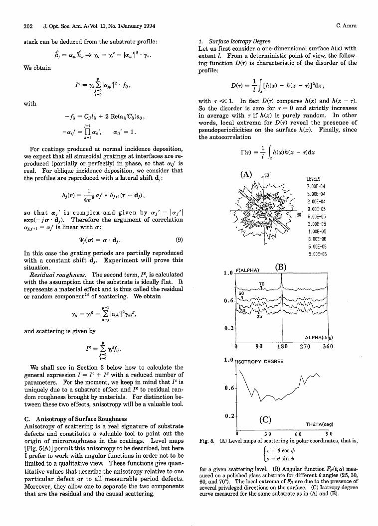
0 30 60 90(A) Level maps of scattering in polar coordinates, that is,
{x= 0 cos
y = 0 sin
for a given scattering level. (B) Angular function FN(0, a) mea-sured on a polished glass substrate for different 0 angles (25, 30,60, and 70°). The local extrema of FN are due to the presence ofseveral privileged directions on the surface. (C) Isotropy degreecurve measured for the same substrate as in (A) and (B).
C. Amra
Vol. 11, No. 1/January 1994/J. Opt. Soc. Am. A 203
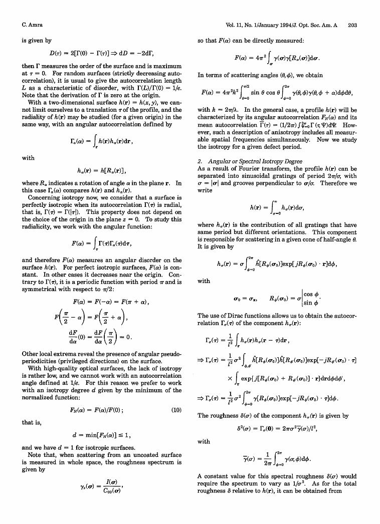
is given by
D(T) = 2[F(0) - r()] => dD = -2dF,
then F measures the order of the surface and is maximumat = 0. For random surfaces (strictly decreasing auto-correlation), it is usual to give the autocorrelation lengthL as a characteristic of disorder, with (L)/r(O) = 1/e.Note that the derivation of F is zero at the origin.
With a two-dimensional surface h(r) = h(x,y), we can-not limit ourselves to a translation - of the profile, and theradiality of h(r) may be studied (for a given origin) in thesame way, with an angular autocorrelation defined by
ra(a) = fh(r)ha(r)dr,
with
ha(r) =h[Ra(r)],
where Ra indicates a rotation of angle a in the plane r. Inthis case ra(a) compares h(r) and ha(r).
Concerning isotropy now, we consider that a surface isperfectly isotropic when its autocorrelation R(-) is radial,that is, r(T) = F(171). This property does not depend onthe choice of the origin in the plane z = 0. To study thisradialicity, we work with the angular function:
F(a) = f r(1)Ta(T)d T,
and therefore F(a) measures an angular disorder on thesurface h(r). For perfect isotropic surfaces, F(a) is con-stant. In other cases it decreases near the origin. Con-trary to F(r), it is a periodic function with period r and issymmetrical with respect to ir/2:
F(a) = F(-a) = F(7r + a),
F(f- _a) = F + a) ,
dF (0) = dF ir) = .da da \2
Other local extrema reveal the presence of angular pseudo-periodicities (privileged directions) on the surface.
With high-quality optical surfaces, the lack of isotropyis rather low, and we cannot work with an autocorrelationangle defined at l/e. For this reason we prefer to workwith an isotropy degree d given by the minimum of thenormalized function:
FN(a) = F(a)/F(0); (10)
that is,
d = min[FN(a)] < 1,
and we have d = 1 for isotropic surfaces.Note that, when scattering from an uncoated surface
is measured in whole space, the roughness spectrum isgiven by
I(0.)
C 00( a.)
so that F(a) can be directly measured:
F(a) = 4rJ y(o)y[Rc(o)]do .
In terms of scattering angles (0,4)), we obtain
C I/2 27T
F(a) = 47r2k2 J sin 0 cos O y(O,4)y(0,4) + a)ddO,
with k = 2ir/A. In the general case, a profile h(r) will becharacterized by its angular autocorrelation FN(a) and itsmean autocorrelation F(r) = (1/27r) f,0 r&(, T)dI How-ever, such a description of anisotropy includes all measur-able spatial frequencies simultaneously. Now we studythe isotropy for a given defect period.
2. Angular or Spectral Isotropy DegreeAs a result of Fourier transform, the profile h(r) can beseparated into sinusoidal gratings of period 2r/o, witho = Ioj and grooves perpendicular to o/o Therefore wewrite
h(r) = J h,(r)do-,
where h,(r) is the contribution of all gratings that havesame period but different orientations. This componentis responsible for scattering in a given cone of half-angle 0.It is given by
27h,(r) = crJ h[RA(ao)]exp[jRO(ao) r]d,
with
cOS 4)o010= 1Z, R (cro)j = 0-sin4)
The use of Dirac functions allows us to obtain the autocor-relation F0 (T) of the component h,(r):
F"I(T) = 12 fh(r)h,(r- )dr,
> F.(r) = 1 c2 f h[R (.O)]h[R (ao.)]exp[-jR (oo)* ]
X f exp{j[R,6(a0) + Ry(ao)] r}drddq',r
> F(T) = r2 f y[Rp(ar)]exp[- jR0(ro) * ]dO.
The roughness 8(o-) of the component h,(r) is given by
82(o.) = F(o) = ( )/2
with
1 2
-y(O,) =- y(o; O)do.27r "_o
A constant value for this spectral roughness 8(o-) wouldrequire the spectrum to vary as 1/cr2. As for the totalroughness 8 relative to h(r), it can be obtained from
C. Amra
204 J. Opt. Soc. Am. A/Vol. 11, No. 1/January 1994
82 = 12 - W (c)do =, f d,.
For an isotropic surface, y(a.) is radial, and we obtainthe autocorrelation
rf(T) = 2 7r 2Y(0)J ()
where Jo is the zeroth-order Bessel function. The spec-tral correlation length L(Co) varies as 1/a.
For a nonisotropic surface, we characterize the isotropyof the component ha(r) with the angular autocorrelationof Subsection 2.C.l:
F0 (a) = f F.(T)r&[Ra(T)]dT ,
X F0(a) = cr4I V(c0)WV( 4)' f exp[-jR.(ao-) ]
x exp[-jR(oo) R(T)]d.
Since R#(ao) R) = Ry_,(o 0 ) , we obtain
(2ff
F,(a) = 4 20r4 J y(VX,4)y(o,4) + a)d4,
and therefore we are able to define an isotropy degreed(Cr) for each spatial frequency:
d(o-) = min.[FN(o-, a)],
with
2ev
FN(0,) F,.(a) fV(0,A)y(0 4) + a)d)
2sr~~~~~o
C = sin 0. (11)A
Note that the expression of F,(a) is rather intuitive (ex-cept for the a' dependence), since it is a single integrationover the angle. Figures 5(B) and 5(C) give examples ofangular functions and an isotropy degree curve, respec-tively, measured on the same substrate. These functionscomplete the qualitative view of the level maps given inFig. 5(A). They allow us to detect approximately 10 spe-cific directions on the surface, whatever the spatialfrequency. However, depending on a, the anisotropy isless or more marked. We notice that the perfect sym-metry of the angular functions proves the quality of themeasurements.
3. Case of Multilayer StacksWith an optical coating we do not have any direct informa-tion on a particular interface, but we can work with angu-lar functions F' calculated from the scattering values:
F()= 2
F'(a) = k 2f 0Fo'(a)sin 0 cos 0 d, (12)
with
k = 2r/A,
J24
F'(a) = f= I(O, 0)I(O,, + a) d+.i =o
(13)
These functions are connected with the anisotropyof interface defects, provided that scattering is measuredat normal illumination (i = 0) and with a nonpolar-ized incident beam (isotropic scattering for isotropicsurfaces X real correlation aij).
With the normalized function FN'(a), the value of anisot-ropy depends on the weight of the optical terms C0j(0) andtherefore varies with the design of the stack. Moreover,owing to the sin 0 cos 0 factor, low spatial frequencieshave predominant weight and mask information relativeto higher spatial frequencies. For this reason we workessentially with the normalized angular function FN'(0, a).Note that, in the case of complex correlation, aj' dependson polar angle , and FN'(0, a) will have a period 2vr (insteadof ).
In Section 4 below we show how this angular anisotropyof the multilayer provides an additional equation forsolving the inverse problem.
3. NUMERICAL CALCULATION
For easy analysis of experiment, it is necessary to befamiliar with the effect of parameters, which is pre-sented here. In particular, it is shown how numericalcomputation can be performed with a reduced number ofparameters.
It is considered in this section that the substrate rough-ness spectrum has been measured before coating is done.
A. Causal Component
1. Cutoff FrequencyWhen the substrate effect is predominant, calculation ofthe causal scattering PC requires knowledge of the correla-tion functions aj'(o.) that describe reproduction of gratingsat interfaces.
As discussed in Ref. 7, the grating periods responsiblefor scattering at low 0 angles are much larger than thelayer thickness and tend to be perfectly replicated. Forsmaller defect periods, partial replication is involved, andwe consider that materials act as low-pass filters on theinterfaces. So laj'(o.)l = fj(c) = lajj+i'l is a decreasingfunction with unity value at the origin, and we chooseto write
fj(c) = 1 + ( C)]2 (14)
where cj is a cutoff frequency characteristic of the (j)-layer material. Notice that any other low-pass filter couldbe used.
Moreover, it is reasonable to expect that all layers of thesame material have the same action at interfaces in thestack, so that f,(c) = fH(0) or fL(r), where H and L desig-nate high- and low-index materials. In other words,prediction of causal scattering I' requires two cutoff fre-quencies, OeH and crL (for real correlation), for a stack oftwo materials, whatever the number of layers.
C. Amra
Vol. 11, No. 1/January 1994/J. Opt. Soc. Am. A 205
-310
10-10
-o6
107-7
10
100 30 60 s0
THETA(deg)
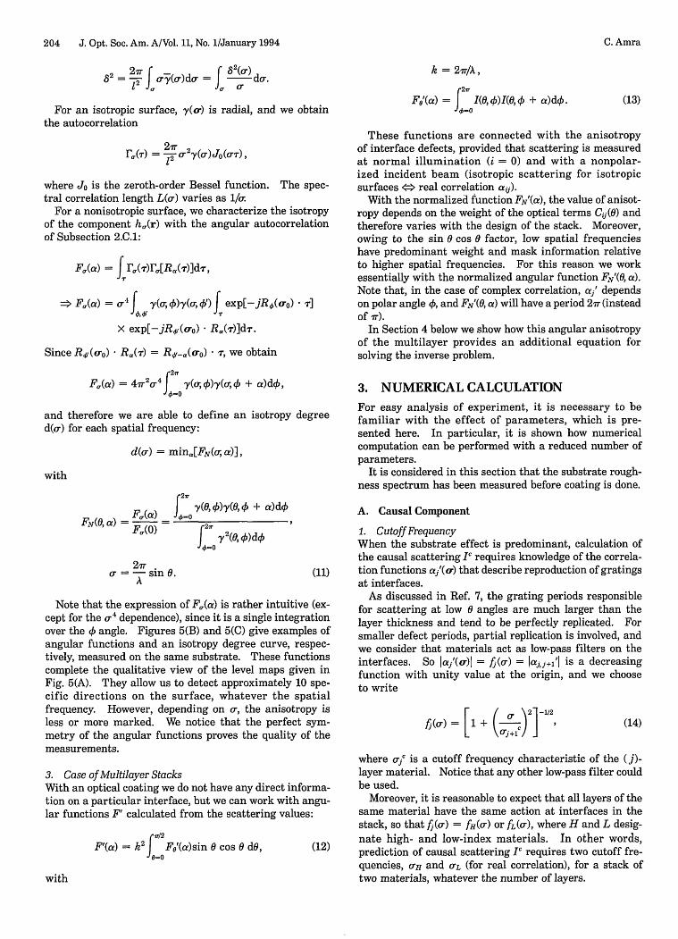
Fig. 6. Influence of cutoff frequency o-' on the angular causalscattering from a single (2H) layer of TiO2. The case o = isthat of perfect correlation.
the curve calculated with Pij = 1 and at large 0 it is closeto the curve calculated with Pij = 0. This clearly empha-sizes the limit of the (,Bij) model.
2. Correlation PhaseAs shown in Subsection 2.B, a'(ao) is complex when thedeposition of material is performed at oblique incidence(,B, ) ( from the sample normal, ; from the polar angle)on nonrotating substrates. Following Ref. 25, we con-sider that the layers grow under incidence (a, C) given bytan a = 1/2 tan P. Therefore layer (j) reproduces inter-faces (j) defects with a lateral shift:
10
102
10 2104
-a
10 A
,-6, 1107
10-10 30 60 90
THETA(deg)Fig. 7. Influence of ac on the angular scattering from a narrow-band filter (M5 6L M5). Curve 1 is calculated with the causalmodel and CH = YL = 12 Lm-'. Curves 2 and 3 are calculatedfrom the i83j model for f3ij = 1 and Sij = 0, respectively.
In fact, we must also take account of the influence ofthickness on the correlation; strictly speaking, cc" varieswith thickness e. However, experiment does not detectany difference in ocr, whether the optical thickness isAo/4 or 12AO/4. Moreover, since we work with classicalquarter-wave or half-wave stacks, all H or L layers havethe same thicknesses and involve only one value of oH(e)or L(e), respectively.
With single layers, finite values of em cause the angularscattering to have local minima (Fig. 6) at directions 0that verify that
laoiI2Coo + C11 + 2a0o Re(Col) 0.
All extrema lead to the correlation value a0j(0) 0.7 thathas to be connected with the antiscattering effect2 4 thatwas shown to occur for particular values of the layer opti-cal thickness. Indeed we know that scattering can be re-duced after coating, because of destructive interferencesamong the scattered waves. For a half-wave TiO2 layer,annulment of scattering may be obtained in the whole an-gular range, provided that the roughness ratio is 80/8 0.7. However, this effect requires the sources to be co-herent, that is, oi(c) = 1, which leads to a 1(c) = 0.7.This constant value of a0 l is no longer possible with ourlow-pass filter [f(r) = 1 at a = 0], unless we introduce anonunity gain for the filter. Therefore scattering can bezero only at particular angles given by a(Cr) - 0.7, withar $ a.
In Fig. 7 it is shown that, relative to a narrow-bandFabry-Perot filter, the influence of or' is rather high be-cause a'(r) is involved at a power k. At low 0 angles, a'(cr)is close to unity, but at large angles we have a'(cr)k << 1.This explains why at low 0 angular scattering is close to
dj = 1 ej tan P Cos 2 t n sin ~ (15)
where e is the layer thickness and the argument of corre-lation is
W (a) = a- dj.
Finally, correlation is written for quarter-wave stacks as
aH (a) = fH(r)exp(-ja dH)
or
aL (a) = fL(cr)exp(-jao dL)
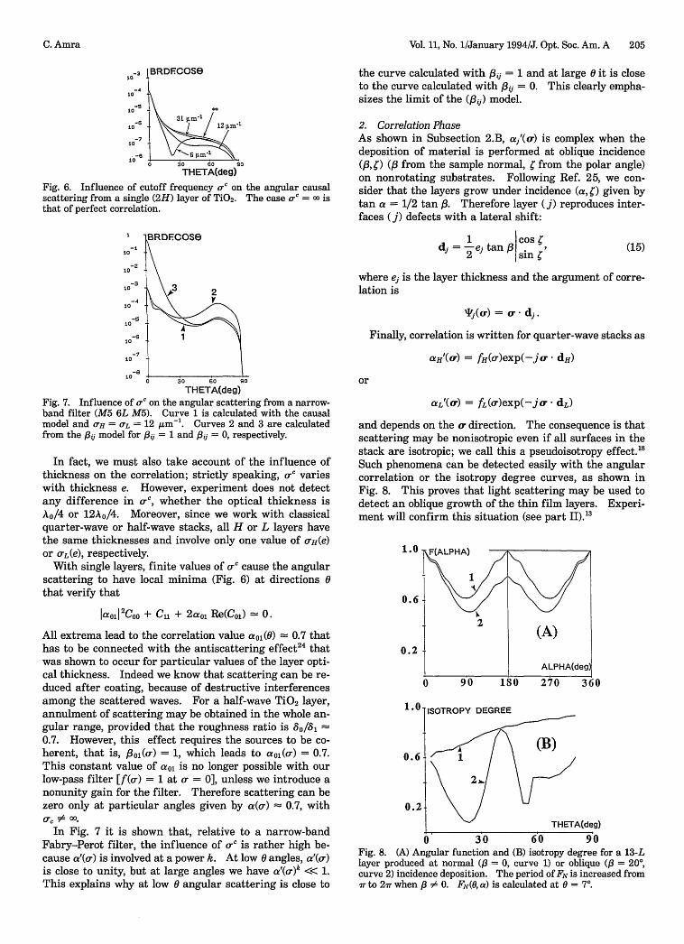
and depends on the a. direction. The consequence is thatscattering may be nonisotropic even if all surfaces in thestack are isotropic; we call this a pseudoisotropy effect."Such phenomena can be detected easily with the angularcorrelation or the isotropy degree curves, as shown inFig. 8. This proves that light scattering may be used todetect an oblique growth of the thin film layers. Experi-ment will confirm this situation (see part II)."3
1.0
0.6
0.2 4
) 4 9'0 180
1 .JISOTROPY DEGREE
0.6
0.2-
270 360
. THETA(deg)
0 30 60 90Fig. 8. (A) Angular function and (B) isotropy degree for a 13-Llayer produced at normal ( = 0, curve 1) or oblique ( = 20,curve 2) incidence deposition. The period of FN is increased fromir to 2ir when ,1 # 0. FN(, a) is calculated at O = 7°.
.F(ALPHA)
1
2I (A)
ALPHA(deg)C - l -
C. Amra
206 J. Opt. Soc. Am. A/Vol. 11, No. 1/January 1994
B-3 RDECOSe10
-4
i05 2 3
10-
0 30 60 s0
THETA(deg)
Fig. 9. Influence of residual roughness on the angular scatteringfrom a single layer. All residual spectra have autocorrelationlength Lg = 100 nm. Curve 1 is calculated for g = 0, curve 2for 8g = 0.2 nm, and curve 3 for 5g = 0.5 nm. All curves are thesum of the causal and residual scattering.
Note that in the polar plane = + r/2, scattering isnot altered by the pseudoisotropy effect.
B. Residual or Random ComponentCalculation of the residual scattering Ig requires two re-sidual spectra, yH9 and l9, whatever the stack. Thesespectra are isotropic and will be taken as Gaussian func-tions; for instance,
YH(0.) = 8H2LH' exp[-(crLH/2)2].4ir
(16)
The expressions of yH9 and yL9 involve four parameters,except if we consider that the spectra are constant.
For each spectrum the pair (g,Lg) is not necessarilyunique, because of the limited range of measurable spatialfrequencies. However, there is only one value for themeasurable residual roughness 8 , obtained by integrationof Yg:
8r2 = 2 fUWX cyg(a)dc,0min
where cmin = 2r/A sin Omin and max = 2r/A are the mea-surement limits. We obtain
8rj2 = 8g2 {exp[_(crminLg/2)2 ] - exp[-(crmaxLg/2) 2 ]}
> 8^ 2 tg2 {1 - exp[-('rLg/A)2]}.
The presence of 8r always increases the scattering in thewhole angular range (Fig. 9).
4. INVESTIGATION METHOD
The analytic functions that are used to describe the low-pass filters f(em) and the residual spectra y g(o-) were intro-duced for easier computation. In fact, experiment willgive the shape of these functions and validate our choice.Here we work with coatings produced at normal incidenceso that correlation is real and isotropic. Then, at eachdirection 0, measurement of the mean section 'm of angu-lar scattering provides a first equation:
Im(0) = IC[ s(0), aH(0),aL(0)]
+ I9[yHa(0)HyL9(0), aH(O), aL(0)], (17)
where X designates a mean value over polar angle k:
-(0) = (1/ 27Xf(0) = (1/2 7r) f0J X(0, O) d.
i o
The mean substrate spectrum (0) can be easily mea-sured for opaque substrates before coating," and thereforeat each direction 0 we have one equation for four un-knowns: afH(0), aL(0), yLg(O), and yHg(0). For non-isotropic substrates a second equation can be obtainedwith the polar dependence of scattering, and the methodis based on the following points:
* According to relations (1) and (13), the angular func-tion Fo'(a) calculated from the scattering values of themultilayer (see Subsection 2.C.3) may be written as
Fo'(a) = E Cij(0)Ck(0)f Yij(0,0)kj(O,4 + a)d4.i, j,k,l I=
When the substrate effect is predominant (causal model),we know that
yii = Viij = ,j,* Iaj, p' 2s.
Moreover, at normal-incidence deposition, aij' is real anddepends only on 0. In these conditions we obtain for theangular correlation of the causal scattering
Fo'(a) = Fo'"(a) = g(0) :: V(O, y O)y( 4) + )dO,
with
g(O) 2,Cij C aij' ahl' * aj p,2 atl t2i,j,k,l
and therefore we have
Fo"(a) Fo(a) =, FN"(0, a) = FN(0, a).Fo`'(0) -Fo(0)
(18)
This proves that, in the absence of residual roughness(Ig = 0), the angular function calculated from the scatter-ing values of the multilayer is identical to that calculatedfrom the substrate spectrum values (see Subsection 2.C.2).This result is valid whatever the low-pass filters at inter-faces and whatever the design of the stack.
* Consider now that Ig 0, and calculate the angularfunction of the multilayer. Separation of scattering be-tween the two components I and Ig leads to
Fo'(a) = F(a) + 4 Ig(0)7C(0) + 2jIg 2(0),
where F6" is obtained from the causal model; that is,FN"'(0, a) = FN(0, a). We obtain
FN'(0, ) =FN(0, a) + B(0)= 1 - 1 - N < 1E X1 +B(0) 1 +B (19)
with
B = tx(2 + x), x = II,, = ,2 (20)
First we note that
aFN 1 -FN, OB (1 + B)2
which proves that residual roughness increases the
C. Amra
Vol. 11, No. 1/January 1994/J. Opt. Soc. Am. A 207
isotropy of scattering. Moreover,
aFN' 1 aFN aFNda 1 + B a da
so that FN' and FN have same extrema: the effect of Igis to reduce the contrast of the angular function of thesubstrate.
* For our application the result of interest is that theisotropy degree curves measured before (d) and after (d')coating are given by
Eq. (19) * d'(0) = d(O) + B(6)1 + B(O)
so that the factor
B(0) = d'(0) - d(o)1 - d'(0)
is known. Therefore the ratio x of residual to causal scat-
tering can be directly measured:
Eq. (20) * x(0) = I = -1 + [1 + B(0)/(0)] , (21)
where is deduced from substrate measurements. Thelatter equation is the required additional equation for theinverse problem and proves that the residual spectra arefunctions of the low-pass filters:
[yH (0),^yL(0) = h[aH(O), aL(6)] -
Combining Eqs. (17) and (21) leads to
Im(0) = (1 + x)I" = [1 + B(0)/1(0)] 1 2
xI [- y(0), all(O), aL(0)] (22)
Therefore the angular scattering Im, of a multilayer can befitted with only two parameters, aH(O) and aL(O). Severalsolutions may still be possible and are described by aL =
k(aH), leading to
(yH1,yzj) = haH, k (aH)]-
However, the problem can be perfectly solved for singlelayers, for which reason they play an essential role andmust be the starting point for more-complex investigation.
Now let us summarize the situation. Experiment (seepart II3) will lead us to work in the following way:
* Mean sections and isotropy curves of scattering mustbe measured before and after coating. The substratespectrum ys(O0, 4) is extracted.
* Check that the angular functions FN'(0, a) are per-fectly symmetrical in the whole range of 0, in order to besure of measurement quality.
* Compare the isotropy degrees measured before (d)and after (d') coating: any difference observed betweenthese curves proves the presence of residual roughness,whatever the low-pass filters and whatever the design.
* When d(O) = d'(0) we can be sure that residualroughness is zero (I << I), although we have not per-formed calculations until now. Then it remains to fit themean section Lm(0) of scattering with the causal com-ponent I, that involves two correlation functions, aH(O)
and aL(O). The solution is immediate for single layers.For multilayers we use the single-layer parameters tostart the investigation.
* When d(O) < d'(0) we start the investigation withaH(O) = aL(O) = 1 and search for the residual spectraH1 g(0) and YLy(0) that allow us to fit the isotropy curve d'(0)
after coating. For a single layer, the solution (a,yg) isunique and the problem can be perfectly solved from rela-tion (22). Note that when a is decreased or increased, thesubstrate effect is decreased or increased, respectively,and a lower or higher, respectively, residual roughness isenough to explain the increase of isotropy after coating.Since both the causal and the residual scattering are re-duced or increased, respectively, the agreement is lost onthe mean section m (0) of angular scattering, which recallsthe uniqueness of the solution (a,yg).
5. SENSITIVITY OF THE STACKS
One question now is about the sensitivity of the method tothe microstructural parameters of the thin-film materials.Which design is the most sensitive to residual roughness?Does sensitivity increase with the number of layers?How can we reduce the substrate effect IP with respect tothe material effect Ig?
In fact, the sensitivity of angular scattering to residualroughness is given by the ratio of residual to causal scat-tering: x = (I - 1")/Ig Ig/I'. Following Eq. (7), weknow that
pI = Vjfi,
j=ow=o
with
f = Cijlij + 2 Re(ajjCk,)sij.
If we assume in the first stage that replication is perfectand that residual spectra are identical, we have
aH = aL = 1,
which leads to
Yj = Ys + (P - )yg = s + Y/g.
Therefore the sensitivity is given by
x = I/I" = S() L,Vs
with
S(6) = p - E f i/ t f(3 -
It can be seen immediately that a low substrate rough-ness is necessary for an increase in the sensitivity. Forinstance, a 3-nm substrate effect will completely mask(yg << y) the residual scattering intrinsic to fine micro-structure materials.
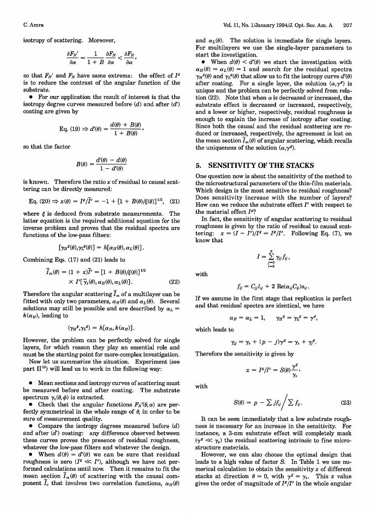
However, we can also choose the optimal design thatleads to a high value of factor S. In Table 1 we use nu-merical calculation to obtain the sensitivity x of differentstacks at direction 0 = 0, with yg = ys. This x valuegives the order of magnitude of Ig/1 c in the whole angular
C. Amra
YH =YZ = g,
(23)
208 J. Opt. Soc. Am. A/Vol. 11, No. 1/January 1994
Table 1. Values of the Sensitivity x of Angular Scattering to Residual Roughness, Calculated forDifferent Designsa
DesignH 2L Al 2H L M15 2H2L2H M5 6L M5
Sensitivity 0.16 0.26 1.0 10.0 10.7 12.0 20.0 5300
'Calculation is performed at the design wavelength for direction = 0, with yg = ys and o, = .
range ( -> 90°), except for the Fabry-Perot filter, whosesensitivity strongly decreases at large angles 0.
First we note that for single layers the 2H and L layersare largely the most sensitive to residual roughness(x 10); this result is due to an antiscattering effect thatoccurs for the causal scattering.2 4 On the other hand, theH and 2L layers could be eliminated for our investigation(x < 0.3). The case of an opaque Al layer does not modifythe sensitivity (x = 1), since calculation is performed forperfect replication and ys = 7 g. We note that for multi-layers, although the spectrum yjg is increased at each inter-face, no significant difference in sensitivity is observedbetween a 15-layer mirror and a 2H-layer mirror. This isan interesting result and proves that it is not worth usingcomplex stacks. Finally, the greatest sensitivity is ob-tained for the absentee-layer stack 2H2L2H, which leadsto x = 21. This result is due to the fact that the scatteredfields at interfaces are in phase opposition by pairs, whichreduces the substrate effect I with respect to residualscattering Ig. This sensitivity may be increased with thenumber of layers.26 Note that for the narrow-band filterthe high value (x = 5300) is due to the same phase opposi-tion of the scattered fields by pairs from each side of thespacer layer at direction 0 = 0. However, this value rap-idly falls to x 9 at direction = 30°.
We may also study the sensitivity of isotropy to residualroughness. Insofar as we have shown that the causalscattering does not modify the substrate isotropy, this sen-sitivity is given by
B 1-d 1- dI+B d d
It can immediately be seen that this sensitivity dependson the substrate isotropy. For instance, d > 0.5 leads toy < 1, and this is true whatever the stack design. There-fore it is easier to work with substrates that have a markedanisotropy.
The ratio y/x of the sensitivities of isotropy degree (y)and of mean section of angular scattering (x) to materialeffect is given by
1- d (2 + x)d 1 + ex(2 + x)
Consider a mirror (x 12) produced upon a substratesuch as d > 0.5. Therefore y < 1 and y/x < 1/x. In thiscase the angular scattering of the mirror is 10 times moresensitive to residual roughness than is the isotropy degree.This explains why the isotropy may appear not to be modi-fied by the coating, although the angular scattering isstrongly different from the causal scattering. In otherwords, we may fit the isotropy without fitting the angularscattering (or the inverse). On the other hand, whend < 0.5, the isotropy may be the most sensitive to residualscattering.
6. CONCLUSION
Scattering can be separated into two components thattake their origins from different phenomena. The firstone, I, is called the causal scattering and represents asubstrate effect; it is characteristic of the reproduction ofsubstrate defects at all interfaces of the stack. Its calcu-lation requires two low-pass filters that describe the actionat interfaces of the high- and low-index materials of thecoating. The second component, I, is called the residualscattering and represents a materials effect. It is due toa residual random roughness brought by and intrinsic tothe materials in thin-film form. Its calculation requirestwo residual spectra characteristic of the high- and low-index materials. These two components are in competi-tion, and their ratio depends on substrate and residualroughness values as well as on the design. It has beenshown that the greatest sensitivity to residual roughnessis obtained for absentee-layer stacks. Moreover, single 2Hor L layers should be used instead of more complex stacksto characterize the materials microstructure.
The angular isotropy of scattering appears to be a valu-able tool for separating these components. The main re-sult is that the substrate roughness spectrum and thecausal scattering have identical isotropy signatures, what-ever the low-pass filters at interfaces and whatever thedesign. In other words, any increase of isotropy aftercoating proves the presence of residual roughness. Thispolar dependence of scattering provides an additionalequation that allows the inverse problem to be perfectlysolved for a single layer. For each material, the extractionof the low-pass filter and of the residual spectrum consti-tutes the starting point for investigation of multilayers.
Light scattering may also be used to detect an obliquegrowth of the thin-film materials. Oblique depositionleads to complex correlation that modifies the causalisotropy signature. This is clearly illustrated with theangular functions or the isotropy degrees.
All these investigation tools permit a detailed analysisof the experiment, which is given in part II of this study."
APPENDIX A: LIST OF SYMBOLS
A Illumination wavelengthi0
PCi0(0, 4))I(0, )I,,,(0, 0)DX(0)IC(0, 4))
Illumination incidence angleScattering angle from the sample normalPolar scattering angleNumber of layers of the optical coatingOptical factor involved in scattering calculationCalculated angular scattering at direction (0,4O)Measured angular scatteringTotal scattering losses integrated in whole spaceMean value of function X(0, 4) over polar angle 4Substrate effect or causal component of the
angular scattering
C. Amra
Vol. 11, No. 1/January 1994/J. Opt. Soc. Am. A 209
g(O) Material effect or residual component of theangular scattering
r Cartesian coordinates (x, y) in the mean plane(z = 0) of the rough interface
hi(r) Interface (i) profileo/2ir Spatial frequencya' Modulus of a.hj (u) Fourier transform of hi(r)
hi(o) Conjugate complex of hi (a)yij (a) Cross-correlation spectrum between interfaces
(i) and (j)yjj ( ) Roughness spectrum of interface (j)Siy Roughness or root mean square of interface ()rii Roughness ratioai (0) Cross-correlation coefficient between interfaces
(i) and (j),8ij () Cross-coherence coefficient between scattering
sources at interfaces (i) and (j)aj(r) Replication function characteristic of layer
(j + 1)aj'(or) Fourier transform of the replication function
aj(r)aH (fa) Describes replication of defects at interfaces by
the high-index materialaL'(a) Describes replication of defects at interfaces by
the low-index materialTj (or) Argument of aj'(o-)aej+i" Cutoff frequency characteristic of a'(or)a '(o) Product of different aj'(u)dj Lateral shift of gratings resulting from oblique
growth of the layersh5(r) Substrate profileVs(O6) Substrate roughness spectrumVj"(o) Roughness spectrum of interface (j) that is
due only to replication of substrate roughnessthroughout the multilayer
gj(r) Residual random roughness brought by layer(j + ) at interface (j)
yjfg(o) Residual roughness spectrum brought by layer(j + 1) at interface (j)
yH9(o-) Residual roughness spectrum brought by thehigh-index material at interfaces
yLg(om) Residual roughness spectrum brought by thelow-index material at interfaces
a (o) Cross-correlation coefficient between residualroughnesses
Vyjg(o) Roughness spectrum of interface (j) that is dueonly to residual roughnesses brought by mate-rials and replicated throughout the multilayer
aig Root mean square of Gaussian autocorrelationfunction
Lg Autocorrelation length of Gaussian autocorrela-tion
Sr Residual roughness obtained by integration ofroughness spectrum brought by materials inthe optical-frequency bandwidth
FrT) Autocorrelation function of h(r)ra(a)F".(T)
F(a)FN(a)d
Angular correlation of h(r)Autocorrelation of h(r)Angular correlation of F(i)Normalized F(a) functionIsotropy degree of the bare substrate, that is, the
minimum of FN(a)
h,(r) Spectral component of h(r), including all gratingsthat have same period (21r/om) but different ori-
8(Cm)F-(a)FN(0, a)
entations r/mRoughness of ha(r)Angular correlation of 1*r)(Normalized F,(a) function
F'(a) Angular correlation of scattering I(0, ) over nor-mal (0) and polar () angles
Fe'(a) Angular correlation of scattering (0, 4) over polarangle
FN'(0, a) Normalized Fe'(a) functiond(8) Spectral isotropy degree of the bare substrate
roughness, that is, the minimum of FN(0, a) atdirection 0
d'(0) Spectral isotropy degree of scattering fromthe optical coating that is, the minimum ofFN'(0, a) at direction 0
B(O) Factor for calculating the increase of isotropyafter coating
Anisotropy constant characteristic of the baresubstrate
x Ratio of material effect to substrate effect, thatis, the sensitivity of angular scattering to re-sidual roughness
y Sensitivity of isotropy degree to residual rough-ness
/3 Incidence deposition angle, from the sample
a
normalPolar deposition angleDirection of growth of the layers from the
sample normal
REFERENCES1. J. M. Bennett and L. Mattsson, Introduction to Surface
Roughness and Scattering (Optical Society of America,Washington, D.C., 1989).
2. J. M. Eastman, "Surface scattering in optical interferencecoatings," Ph.D. dissertation (University of Rochester,Rochester, N.Y., 1974).
3. C. K. Carniglia, "Scalar scattering theory for multilayer opti-cal coatings," Opt. Eng. 18, 104-115 (1979).
4. S. J. Gourley and P. H. Lissberger, "Optical scattering inmultilayer thin films," Opt. Acta 26, 117-143 (1979).
5. C. Grezes-Besset, C. Amra, B. Cousin, G. Otrio, E. Pelletier,and R. Richier, "Etude de la diaphonie d'un systeme de d6-multiplexage par filtres interf6rentiels. Consequences de ladiffusion de la lumiere par les irregularites des surfaces op-tiques," Ann. Telecommun. 43, 135-141 (1988).
6. J. M. Elson, J. P. Rahn, and J. M. Bennett, "Light scatteringfrom multilayer optics: comparison of theory and experi-ment," Appl. Opt. 19, 669-679 (1980).
7. C. Amra, J. H. Apfel, and E. Pelletier, "Role of interface cor-relation in light scattering by a multilayer," Appl. Opt. 16,3134-3151 (1992).
8. J. M. Elson, J. P. Rahn, and J. Bennett, "Relationship of thetotal integrated scattering from multilayer-coated optics toangle of incidence, polarization, correlation-length, androughness cross-correlation properties," Appl. Opt. 22, 3207-3219 (1983).
9. C. Amra, "Scattering characterization of materials in thinfilm form," in Laser-Induced Damage in Optical Materials1989, H. E. Bennett, L. L. Chase, A. H. Guenther, B. E.Newnam, and H. J. Soileau, eds., Proc. Soc. Photo-Opt. In-strum. Eng. 1438, 309-323 (1990).
10. S. Kassam, A. Duparr6, K. Hehl, P. Bussemer, and J. Neubert,"Light scattering from the volume of optical thin films:theory and experiment," Appl. Opt. 31, 1304-1313 (1992).
11. C. Amra, "First-order vector theory of bulk scattering in op-tical multilayers," J. Opt. Soc. Am. A 10, 365-374 (1993).
C. Amra
210 J. Opt. Soc. Am. A/Vol. 11, No. 1/January 1994
12. C. Amra, L. Bruel, and C. Grezes-Besset, "Comparison ofsurface and bulk scattering in optical multilayers," Appl.Opt. 32, 5492-5503 (1993).
13. C. Amra, "Light scattering from multilayer optics. II.Application to experiment," J. Opt. Soc. Am. A 11, 211-226(1994).
14. C. Amra, D. Torricini, Y. Boucher, and E. Pelletier, "Scatter-ing from optical surfaces and coatings: an easy investiga-tion of microroughness," in Optical Thin Films andApplications, R. Herrmann, ed., Proc. Soc. Photo-Opt. In-strum. Eng. 1270, 72-81 (1990).
15. C. Amra, "Calculs et mesures de diffusion appliques a l'4tudede la rugosit6 dans les traitements optiques multicouches,"J. Opt. (Paris) 21, 83-98 (1990).
16. J. M. Elson, 'Angle resolved light scattering from compositeoptical surfaces," in Periodic Structures, Gratings, MoirePatterns, and Diffraction Phenomena 1, C. H. Chi, ed., Proc.Soc. Photo-Opt. Instrum. Eng. 240, 296-306 (1980).
17. P. Bousquet, F. Flory, and P. Roche, "Scattering from multi-layer thin films: theory and experiment," J. Opt. Soc. Am.71, 1115-1123 (1981).
18. C. Amra and P. Bousquet, "Scattering from surfaces andmultilayer coatings: recent advances for a better investiga-tion of experiment," in Surface Measurement and Character-ization, J. M. Bennett, ed., Proc. Soc. Photo-Opt. Instrum.Eng. 1009, 82-97 (1988).
19. C. Amra, C. Grezes-Besset, P. Roche, and E. Pelletier, "De-scription of a scattering apparatus: application to the prob-
lems of characterization of opaque surfaces," Appl. Opt. 28,2723-2730 (1989).
20. F. E. Nicodemus, "Directional reflectance and emissivity ofan opaque surface," Appl. Opt. 4, 767-773 (1965).
21. C. Amra, P. Roche, and E. Pelletier, "Interface roughnesscross-correlation laws deduced from scattering diagrammeasurements on optical multilayers: effect of the materialgrain size," J. Opt. Soc. Am. B 4, 1087-1093 (1987).
22. P. Roche, E. Pelletier, and G. Albrand, 'Antiscattering trans-parent monolayers: theory and experiment," J. Opt. Soc.Am. A 1, 1032-1033 (1984).
23. P. Roche, P. Bousquet, F. Flory, J. Garcin, E. Pelletier, andG. Albrand, "Determination of interface roughness cross-correlation properties of an optical coating from measure-ments of the angular scattering," J. Opt. Soc. Am. A 1,1028-1031 (1984).
24. C. Amra, G. Albrand, and P. Roche, "Theory and applicationof antiscattering single layers: antiscattering antireflectioncoatings," Appl. Opt. 25, 2695-2702 (1986).
25. A. G. Dirks and H. J. Leamy, "Columnar microstructure invapor-deposited thin films," Thin Solid Films 47, 219-223(1977).
26. C. Amra, "Scattering distribution from multilayer mirrors:theoretical research of a design for minimum losses," inLaser-Induced Damage in Optical Materials, H. E. Bennett,A. H. Guenther, D. Milam, and B. E. Newnam, eds., Natl.Inst. Stand. Technol. Spec. Publ. 752, 594-602 (1986).
C. Amra


![Objective analysis of typographies by image processing ... · Rabbetts, Bennett & Rabbetts’ Clinical Visual Optics, 4th Edt., Butterworth-Heinemann, Edinburgh, UK (2007). [2] ICO,](https://img.pdfslide.fr/doc/110x75/5fb2ca49c815773628379566/objective-analysis-of-typographies-by-image-processing-rabbetts-bennett-.jpg)