Embed Size (px)
Citation preview
1
N°d’ordre : 2014-ISAL-0138 Année 2014
THESE DE DOCTORAT
LUMIERE SUR LA ZIRCONE 3Y-TZP UTILISEE EN IMPLANTOLOGIE ORALE : ETUDE
DE LA RELATION ENTRE LA MICROSTRUCTURE ET LA DURABILITE
Présentée devant
L'Institut National Des Sciences Appliquées De Lyon
Pour obtenir
le grade de Docteur
Ecole doctorale
Matériaux de Lyon
Spécialité :
Science des Matériaux
Par
Clarisse SANON
Docteur en Odontologie
Soutenance prévue le 15 décembre 2014 devant la commission d’examen
Jury
Marc BOLLA Professeur (Faculté d’Odontologie, Nice) Examinateur
Francis CAMBIER Professeur (EMRA, Mons) Rapporteur
Jérôme CHEVALIER Professeur (INSA, Lyon) Directeur de thèse
Thierry DOUILLARD Ingénieur (CLYM, INSA Lyon) Membre invité
Patrick EXBRAYAT Docteur (Faculté d’Odontologie, Lyon) Membre invité
Laurent GREMILLARD Docteur (INSA, Lyon) Directeur de thèse
Bruno JACQUOT Docteur (Faculté d’Odontologie Montpellier) Examinateur
Corrado PICONI Professeur (COI, Rome) Rapporteur
Université de Lyon
MATEIS – UMR CNRS 5510 - INSA de LYON
20, avenue Albert Einstein, 69621 Villeurbanne cedex, France
Cette thèse est accessible à l'adresse : http://theses.insa-lyon.fr/publication/2014ISAL0138/these.pdf © [C. Sanon], [2015], INSA Lyon, tous droits réservés
2
INSA Direction de la Recherche - Ecoles Doctorales – Quinquennal 2011-2015
SIGLE ECOLE DOCTORALE NOM ET COORDONNEES DU RESPONSABLE
CHIMIE
CHIMIE DE LYON
http://www.edchimie-lyon.fr
Sec : Renée EL MELHEM Bat Blaise Pascal 3e etage 04 72 43 80 46 Insa : R. GOURDON [email protected]
M. Jean Marc LANCELIN Université de Lyon – Collège Doctoral Bât ESCPE
43 bd du 11 novembre 1918 69622 VILLEURBANNE Cedex Tél : 04.72.43 13 95 [email protected]
E.E.A.
ELECTRONIQUE,
ELECTROTECHNIQUE, AUTOMATIQUE
http://edeea.ec-lyon.fr
Sec : M.C. HAVGOUDOUKIAN [email protected]
M. Gérard SCORLETTI Ecole Centrale de Lyon 36 avenue Guy de Collongue 69134 ECULLY
Tél : 04.72.18 60.97 Fax : 04 78 43 37 17 [email protected]
E2M2
EVOLUTION, ECOSYSTEME, MICROBIOLOGIE, MODELISATION http://e2m2.universite-lyon.fr
Sec : Safia AIT CHALAL Bat Atrium- UCB Lyon 1 04.72.44.83.62 Insa : S. REVERCHON [email protected]
Mme Gudrun BORNETTE CNRS UMR 5023 LEHNA
Université Claude Bernard Lyon 1 Bât Forel 43 bd du 11 novembre 1918 69622 VILLEURBANNE Cédex
Tél : 06.07.53.89.13 e2m2@ univ-lyon1.fr
EDISS
INTERDISCIPLINAIRE SCIENCES-
SANTE
http://www.ediss-lyon.fr
Sec : Safia AIT CHALAL Bat Atrium – UCB Lyon 1 04 72 44 83 62 Insa : [email protected]
Mme Emmanuelle CANET-SOULAS INSERM U1060, CarMeN lab, Univ. Lyon 1 Bâtiment IMBL
11 avenue Jean Capelle INSA de Lyon 696621 Villeurbanne Tél : 04.72.68.49.09 Fax :04 72 68 49 16 [email protected]
INFOMATHS
INFORMATIQUE ET
MATHEMATIQUES http://infomaths.univ-lyon1.fr
Sec :Renée EL MELHEM Bat Blaise Pascal 3e etage [email protected]
Mme Sylvie CALABRETTO LIRIS – INSA de Lyon
Bat Blaise Pascal 7 avenue Jean Capelle 69622 VILLEURBANNE Cedex Tél : 04.72. 43. 80. 46 Fax 04 72 43 16 87
Matériaux
MATERIAUX DE LYON http://ed34.universite-lyon.fr
Sec : M. LABOUNE PM : 71.70 –Fax : 87.12 Bat. Saint Exupéry [email protected]
M. Jean-Yves BUFFIERE INSA de Lyon MATEIS Bâtiment Saint Exupéry
7 avenue Jean Capelle 69621 VILLEURBANNE Cedex Tél : 04.72.43 71.70 Fax 04 72 43 85 28 [email protected]
MEGA
MECANIQUE, ENERGETIQUE, GENIE
CIVIL, ACOUSTIQUE
http://edmega.universite-lyon.fr/
Sec : M. LABOUNE PM : 71.70 –Fax : 87.12 Bat. Saint Exupéry [email protected]
M. Philippe BOISSE INSA de Lyon Laboratoire LAMCOS Bâtiment Jacquard
25 bis avenue Jean Capelle 69621 VILLEURBANNE Cedex Tél : 04.72 .43.71.70 Fax : 04 72 43 72 37 [email protected]
ScSo
ScSo*
http://recherche.univ-lyon2.fr/scso/
Sec : Viviane POLSINELLI Brigitte DUBOIS
Mme Isabelle VON BUELTZINGLOEWEN Université Lyon 2 86 rue Pasteur 69365 LYON Cedex 07
Tél : 04.78.77.23.86 Fax : 04.37.28.04.48
Cette thèse est accessible à l'adresse : http://theses.insa-lyon.fr/publication/2014ISAL0138/these.pdf © [C. Sanon], [2015], INSA Lyon, tous droits réservés
3
Insa : J.Y. TOUSSAINT [email protected]
*ScSo : Histoire, Géographie, Aménagement, Urbanisme, Archéologie, Science politique, Sociologie, Anthropologie
Cette thèse est accessible à l'adresse : http://theses.insa-lyon.fr/publication/2014ISAL0138/these.pdf © [C. Sanon], [2015], INSA Lyon, tous droits réservés
4
« L’oreille n’est pas faite pour entendre.
On ne dira pas que le lit et le dessin des rives sont faits pour le fleuve ?
Le son a fait l’oreille.
Etudie l’oreille pour connaitre le son, étudie l’œil pour connaitre la lumière »
R.A. Schwaller De Lubicz
Cette thèse est accessible à l'adresse : http://theses.insa-lyon.fr/publication/2014ISAL0138/these.pdf © [C. Sanon], [2015], INSA Lyon, tous droits réservés
5
« Lumières sur la zircone 3Y-TZP utilisée en Implantologie
Orale : étude de la relation entre la microstructure et la
durabilité »
Cette thèse est accessible à l'adresse : http://theses.insa-lyon.fr/publication/2014ISAL0138/these.pdf © [C. Sanon], [2015], INSA Lyon, tous droits réservés
6
Table des matières
INTRODUCTION ....................................................................................................................................... 9
PREMIERE PARTIE : LES IMPLANTS DENTAIRES EN ZIRCONE 3Y-TZP : ETAT DES CONNAISSANCES
ACTUELLES ............................................................................................................................................. 11
1.Historique des implants en céramique .................................................................................. 11
2. Origine et minéralogie de la zircone .................................................................................... 13
3. Structure cristalline de la zircone ......................................................................................... 13
4. Transformation de phase de la zircone 3Y-TZP ..................................................................... 14
4.1 Renforcement par transformation de phase........................................................................... 14
4.2 Dégradation par transformation de phase ou vieillissement .................................................. 15
5. Propriétés de la zircone 3Y-TZP............................................................................................ 17
5.1 Propriétés mécaniques ............................................................................................................ 17
5.2 Propriétés thermiques, électriques et optiques...................................................................... 19
6. La zircone 3Y-TZP en implantologie orale ............................................................................. 20
6.1 Généralités .............................................................................................................................. 20
6.2. Elaboration et mise en forme des implants dentaires en zircone ......................................... 23
6.3 Géométrie ................................................................................................................................ 24
7. Comportement des implants en zircone 3Y-TZP dans l’environnement biologique à court
terme ..................................................................................................................................... 26
7.1 Réactions d’adsorption ............................................................................................................ 26
7.2 Adsorption d’eau et d’ions de la matrice extracellulaire ........................................................ 26
7.3 Adsorption de protéines de la matrice extracellulaire ............................................................ 26
7.4 Réactions d’adhésion cellulaire ............................................................................................... 26
7.5 Réaction tissulaire : l’ostéointégration.................................................................................... 26
7.6 Synthèse des études cliniques réalisées sur les implants en zircone ...................................... 29
8. Comportement des implants dentaires en zircone 3Y-TZP dans l’environnement biologique à long
terme : étude de la durabilité .................................................................................................... 30
8.1 Résistance mécanique des implants en zircone 3Y-TZP ........................................................... 30
8.2 Influence vieillissement des implants dentaires en zircone 3Y-TZP sur leur durabilité ............ 31
9. Conclusion de la première partie ............................................................................................ 32
10. Références bibliographiques de la première partie............................................................. 32
DEUXIEME PARTIE : ETUDE DU MECANISME DE VIEILLISSEMENT ET DE SES EFFETS SUR LA
RESISTANCE MECANIQUE ...................................................................................................................... 37
1 Introduction ........................................................................................................................ 37
2. “Low temperature degradation and reliability of one-piece ceramic oral implants with a
porous surface” ...................................................................................................................... 38
Cette thèse est accessible à l'adresse : http://theses.insa-lyon.fr/publication/2014ISAL0138/these.pdf © [C. Sanon], [2015], INSA Lyon, tous droits réservés
7
2.2 Introduction ............................................................................................................................. 38
2.3 Materials and Methods ........................................................................................................... 40
2.4 Results ..................................................................................................................................... 42
2.5 Discussion ................................................................................................................................ 49
2.6 Conclusions .............................................................................................................................. 51
2.7 Acknowledgments: .................................................................................................................. 51
2.8 Réferences bibliographiques de la deuxième partie ............................................................... 51
TROISIEME PARTIE: DEVELOPPEMENT D’UN PROTOCOLE D’EVALUATION POUR LES IMPLANTS
DENTAIRES EN ZIRCONE ........................................................................................................................ 53
1. Introduction........................................................................................................................ 53
2. “A new testing protocol for zirconia dental implants” .......................................................... 53
2.1 Abstract ................................................................................................................................... 53
2.2 Introduction: ............................................................................................................................ 53
2.3 Materials and method ............................................................................................................. 55
2.4 Results ..................................................................................................................................... 57
2.5 Discussion ................................................................................................................................ 66
2.6 Conclusion ............................................................................................................................... 68
2.7 Acknowledgements ................................................................................................................. 69
3. Apport du FIB à la quantification du phénomène de vieillissement ....................................... 69
3.1 Objectif .................................................................................................................................... 70
3.2 Matériel et méthode ............................................................................................................... 70
3.3 Résultats : Caractérisation de l’implant Zir-Roc ..................................................................... 75
3.4 Discussion ................................................................................................................................ 78
3.5 Conclusion ............................................................................................................................... 80
4 References bibliographique de la troisième partie ................................................................ 80
QUATRIEME PARTIE: MISE EN EVIDENCE DU PHENOMENE DE VIEILLISSEMENT IN VIVO .................... 83
1 Introduction ........................................................................................................................ 83
2 “Study of a type of 3Y-TZP zirconia dental implant presenting in vivo accelerated aging” ....... 83
2.1 Abstract ................................................................................................................................... 83
2.2 Introduction ............................................................................................................................. 84
2.3 Materials and methods ........................................................................................................... 85
2.5 Discussion ................................................................................................................................ 95
2.6 Conclusion ............................................................................................................................... 96
2.7 Références bibliographiques de la 4ème partie ...................................................................... 97
CINQUIEME PARTIE : CONCLUSION ....................................................................................................... 99
ANNEXES .............................................................................................................................................. 101
Cette thèse est accessible à l'adresse : http://theses.insa-lyon.fr/publication/2014ISAL0138/these.pdf © [C. Sanon], [2015], INSA Lyon, tous droits réservés
8
1.Table des figures ................................................................................................................. 101
2. Table des tableaux ............................................................................................................. 103
Cette thèse est accessible à l'adresse : http://theses.insa-lyon.fr/publication/2014ISAL0138/these.pdf © [C. Sanon], [2015], INSA Lyon, tous droits réservés
9
INTRODUCTION
En réponse à une demande esthétique de plus en plus exigeante et face à certains débats concernant
l’innocuité des biomatériaux métalliques, l’approche « sans métal » prend une place importante dans
la thérapeutique odontologique. Les reconstructions « tout céramique » rencontrent un franc succès
auprès des patients et des praticiens, mais pouvons-nous étendre en toute sécurité cette approche «
sans métal » à l’implantologie orale ?
Pour l’application en implantologie orale, la zircone 3Y -TZP semble être un matériau extrêmement
prometteur: elle allie une biocompatibilité à un aspect esthétique satisfaisant et présente aussi des
propriétés mécaniques très supérieures aux autres céramiques. Ces bonnes propriétés mécaniques
sont intimement liées à la microstructure du matériau, elle-même directement liée aux procédés
d’élaboration comme nous l’a rappelé l’alarmante série de ruptures de plus de 800 têtes de
prothèses de hanche en zircone au début des années 2000, et cela quelques années voir quelques
mois seulement après implantation. Cet épisode nous a montré que les procédés de fabrication de la
zircone devraient être parfaitement maitrisés avant l’utilisation à des fins thérapeutiques.
Il existe actuellement dans le commerce, une dizaine de systèmes d’implants dentaires en zircone 3Y-
TZP ; chaque fabriquant développe son propre procédé d’élaboration aboutissant à une
microstructure spécifique. A ce jour, aucune étude n’a été publiée sur la relation existant entre les
microstructures des différents implants et leur durabilité ; par contre des études cliniques font
quelquefois état d’un taux d’échec important, à court terme pour certains implants dentaires.
Notre premier objectif consiste en la mise au point d’un protocole permettant l’évaluation de leur
résistance mécanique tout en prenant en compte la géométrie, la topographie de l’implant et la
direction des forces masticatoires. La stabilité microstructurale au cours du temps pourra être
également évaluée et comparée à celle de la zircone 3Y-TZP dense et polie classiquement étudiée
dans la littérature. C’est ici un objectif qui se veut pragmatique, avec dans cette optique, une grande
volonté de reproductibilité du protocole, afin de permettre l’extension voir la généralisation de son
utilisation par les chercheurs mais également par les différents acteurs du marché de l’implantologie
de la zircone, ce qui permettrait dans un premier temps de s’assurer de la fiabilité du produit fini
utilisé dans les thérapeutiques proposées aux patients.
Notre second objectif, plus fondamental, est la recherche de connaissances sur le comportement de
la zircone 3Y-TZP, en développant de nouvelles méthodes de caractérisation. Cela s’est effectué dans
le cadre d’une recherche associant une approche pluridisciplinaire, des collaborations internationales
faisant intervenir des leaders d’opinion dans ce domaine, par l’utilisation d’outils technologiques
innovants et performants et enfin par la coopération de certains acteurs du milieu industriel
concernés par cette problématique.
Tout ceci a favorisé la recherche au niveau de différentes interfaces, lieux privilégiés de genèse des
innovations.
Ce travail de thèse a été financé par l’Institut Universitaire de France dont le Pr Jérôme Chevalier est
membre depuis novembre 2009, au titre de ses travaux sur la zircone 3Y-TZP en Orthopédie ainsi que
pour son rayonnement international.
Cette thèse est accessible à l'adresse : http://theses.insa-lyon.fr/publication/2014ISAL0138/these.pdf © [C. Sanon], [2015], INSA Lyon, tous droits réservés
10
Ce travail de thèse a été co-encadré par le Pr Jérôme Chevalier et le Dr Laurent Gremillard du
laboratoire Mateis de l’INSA de Lyon, enrichi par l’investissement de Thierry Douillard (CLYM, Mateis)
et par nos collaborations avec le Pr Ralf J. Kohal de la faculté de chirurgie dentaire de Fribourg
(Allemagne), les Dr Guy Courbebaisse et Dr Ricarco Corredor du laboratoire Créatis, laboratoire de
traitement d’image appartenant à l’INSA de Lyon, les Dr Susanne S. Scherer et Dr Maria Catani de la
Faculté de Medecine dentaire de Genève (Suisse), le Dr Nelson R.F.A. Da Silva de la Faculté de
Chirurgie Dentaire de Minas Gerais (Brésil), le Dr Jenni Hjerppe de la Faculté de Chirurgie Dentaire de
New York (Etats-Unis).
Ce travail de thèse s’inscrit dans une des principales thématiques du laboratoire Mateis, laboratoire
de Science des Matériaux, à savoir : établir les relations existant entre paramètres d’élaboration et la
microstructure obtenue puis comprendre et prédire le comportement macroscopique du matériau
en service dans des domaines d’application très variés tels que la santé, l’aéronautique, l’énergie,
etc…
Ce travail de thèse, associant principalement des chirurgiens-dentistes et des chercheurs en Science
des Matériaux, exprime une volonté forte du laboratoire Mateis de se rapprocher du monde dentaire
et plus généralement de l’application biomédicale des matériaux, manifestant ainsi son implication
dans le domaine de la Santé, qui est aujourd’hui une des priorités nationales et européennes.
Dans une première partie, nous présentons de façon exhaustive, l’état des connaissances actuelles
sur les implants dentaires en zircone 3Y-TZP. Cette partie a été extraite d’un chapitre rédigé par
l’auteur, dans l’ouvrage : « Le traité de chirurgie maxillofaciale et d’implantologie orale » qui sera
publié très prochainement par la maison d’édition Elsevier-Masson.
Dans une deuxième partie, nous présentons, sous forme d’une publication internationale dans la
revue Dental materials, les travaux effectués sur la mise en évidence des relations existant entre le
procédé d’élaboration, la microstructure, le comportement mécanique et la sensibilité au
vieillissement à basse température (Low Temperature Degradation) pour un type donné d’implant
dentaire. Il nous semblait primordial de démontrer l’existence de ces interrelations bien connues en
sciences des matériaux mais partiellement en Implantologie Orale.
Dans une troisième partie, nous présentons le protocole développé au cours de nos travaux,
également sous forme d’une publication internationale dans la revue Dental materials. La création
d’un tel protocole à usage préclinique était essentielle au vu des taux d’échecs élevés lors de certains
essais cliniques. Ceci représente donc un intérêt pour les patients et pour les fabricants dans le but
d’optimiser leur produit avant la mise en place sur le marché.
Les conséquences du vieillissement de la zircone 3Y-TZP (LTD) sont assez bien connu en sciences des
matériaux, également en orthopédie mais ceci de façon inopinée, suite à la série de rupture des
prothèses de hanche au début des années 2000. En implantologie orale, les études cliniques publiées
ne prennent toujours pas en compte ce phénomène. L’analyse d’explants issus d’essais cliniques et
l’utilisation de technologies d’imagerie de pointe associées à un traitement numérique des images
ont permis de mettre en évidence l’occurrence de ce phénomène in vivo afin de sensibiliser les
différents acteurs sur cette problématique. C’est donc le sujet de la quatrième partie, qui est
également présentée sous la forme d’un projet de publication.
La cinquième partie représente la synthèse et la discussion des travaux menés dans le cadre de notre
thèse d’Université.
Cette thèse est accessible à l'adresse : http://theses.insa-lyon.fr/publication/2014ISAL0138/these.pdf © [C. Sanon], [2015], INSA Lyon, tous droits réservés
11
PREMIERE PARTIE : LES IMPLANTS DENTAIRES EN ZIRCONE 3Y-TZP : ETAT DES
CONNAISSANCES ACTUELLES
1. Historique des implants en céramique Lors de ces dernières années, les évolutions technologiques concernant les matériaux céramiques, la
demande esthétique accrue de la part des patients et la sensibilisation à la notion de
biocompatibilité ont conduit à développer des matériaux céramiques capables de répondre à la fois
au besoin d’esthétisme et aux sollicitations mécaniques inhérentes à la mastication. Désormais, il
devient possible de remplacer, dans certains cas, les traditionnelles restaurations céramo-
métalliques par des restaurations céramo-céramiques. Le domaine de l’implantologie a également
bénéficié de ces avancées.
Le grand essor de l’implantologie dentaire, telle que nous la connaissons actuellement, débute au
XXème siècle, grâce à l’avancée des techniques chirurgicales et au développement des matériaux. En
effet à cette époque, les chercheurs s’intéressent aux réactions tissulaires des différents matériaux.
En 1977, le professeur P. Bränemark décrit le phénomène d’ostéointégration avec l’utilisation du
titane [1]. Les implants en titane connaissent un grand succès et l’implantologie orale devient le «
gold standard » de la thérapeutique chirurgicale avec un taux de réussite de 96% sur 10 ans [2].
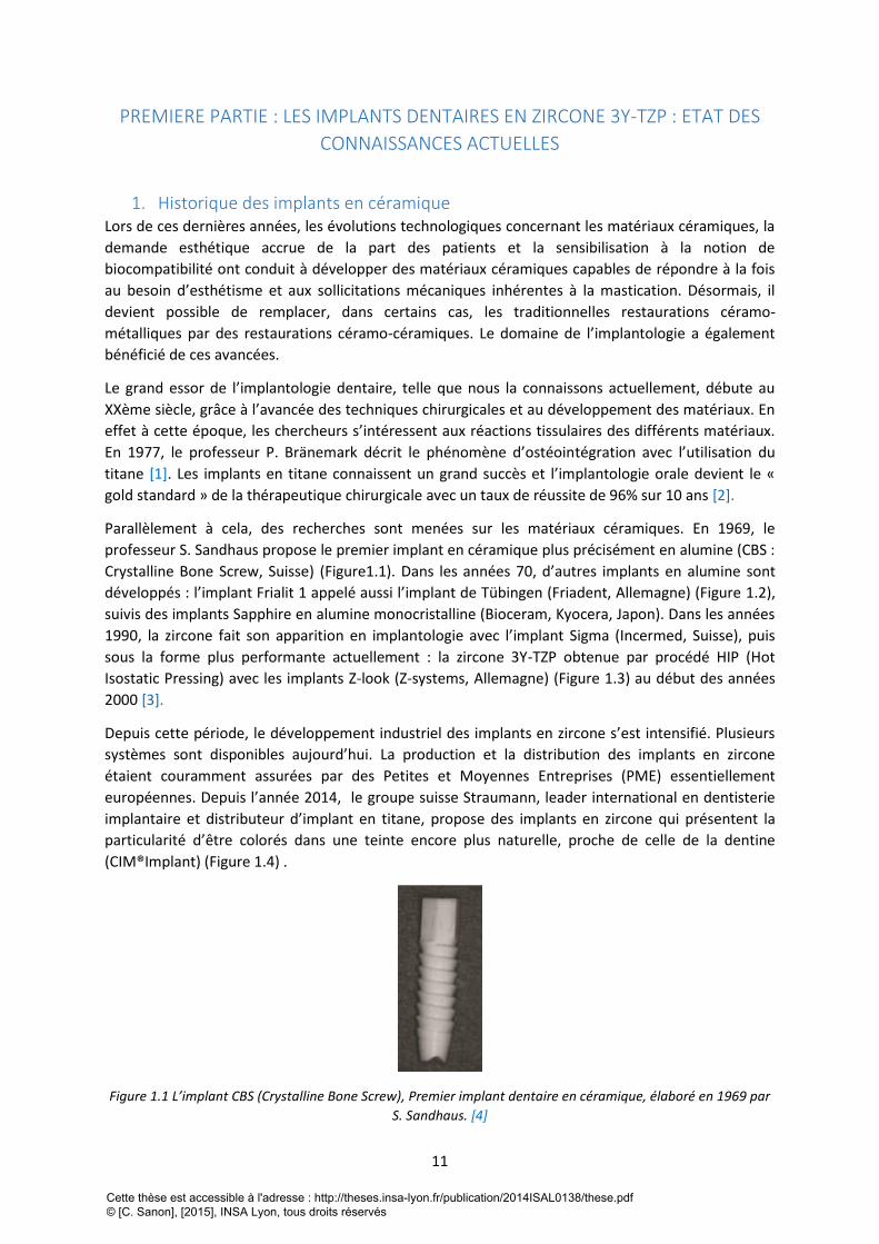
Parallèlement à cela, des recherches sont menées sur les matériaux céramiques. En 1969, le
professeur S. Sandhaus propose le premier implant en céramique plus précisément en alumine (CBS :
Crystalline Bone Screw, Suisse) (Figure1.1). Dans les années 70, d’autres implants en alumine sont
développés : l’implant Frialit 1 appelé aussi l’implant de Tübingen (Friadent, Allemagne) (Figure 1.2),
suivis des implants Sapphire en alumine monocristalline (Bioceram, Kyocera, Japon). Dans les années
1990, la zircone fait son apparition en implantologie avec l’implant Sigma (Incermed, Suisse), puis
sous la forme plus performante actuellement : la zircone 3Y-TZP obtenue par procédé HIP (Hot
Isostatic Pressing) avec les implants Z-look (Z-systems, Allemagne) (Figure 1.3) au début des années
2000 [3].
Depuis cette période, le développement industriel des implants en zircone s’est intensifié. Plusieurs
systèmes sont disponibles aujourd’hui. La production et la distribution des implants en zircone
étaient couramment assurées par des Petites et Moyennes Entreprises (PME) essentiellement
européennes. Depuis l’année 2014, le groupe suisse Straumann, leader international en dentisterie
implantaire et distributeur d’implant en titane, propose des implants en zircone qui présentent la
particularité d’être colorés dans une teinte encore plus naturelle, proche de celle de la dentine
(CIM®Implant) (Figure 1.4) .
Figure 1.1 L’implant CBS (Crystalline Bone Screw), Premier implant dentaire en céramique, élaboré en 1969 par
S. Sandhaus. [4]
Cette thèse est accessible à l'adresse : http://theses.insa-lyon.fr/publication/2014ISAL0138/these.pdf © [C. Sanon], [2015], INSA Lyon, tous droits réservés
12
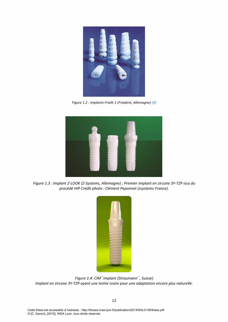
Figure 1.2 : Implants Frialit 1 (Friadent, Allemagne) [4]
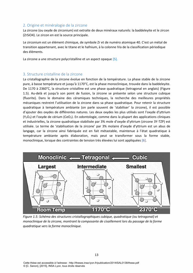
Figure 1.3 : Implant Z-LOOK (Z-Systems, Allemagne) ; Premier implant en zircone 3Y-TZP issu du procédé HIP Crédit photo : Clément Peponnet (zsystems France).
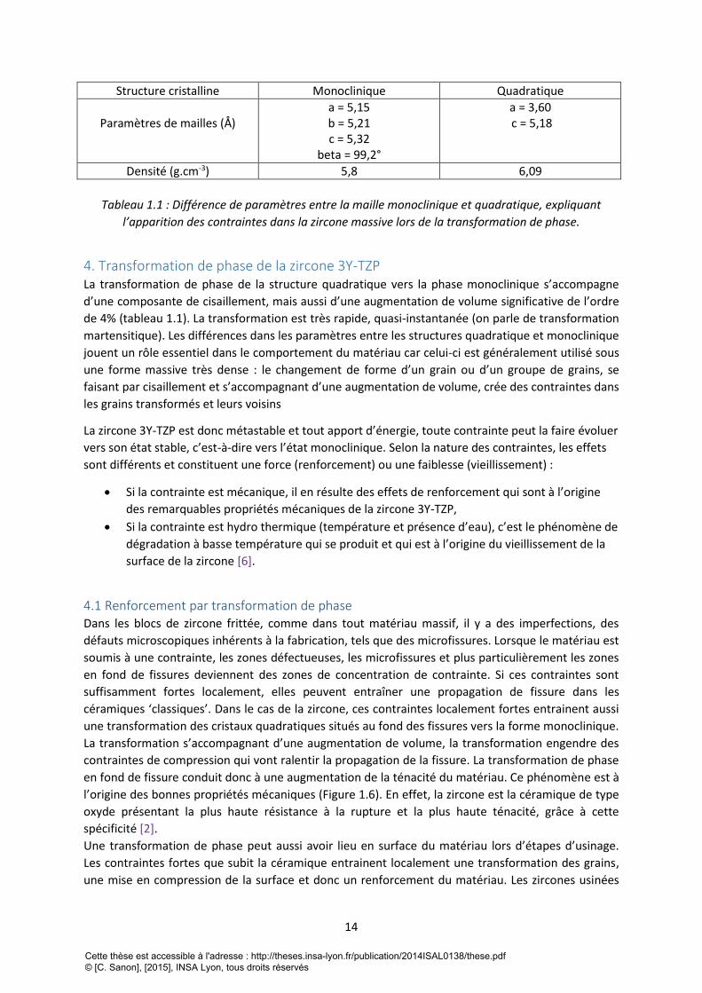
Figure 1.4: CIM®implant (Straumann®, Suisse) Implant en zircone 3Y-TZP ayant une teinte ivoire pour une adaptation encore plus naturelle.
Cette thèse est accessible à l'adresse : http://theses.insa-lyon.fr/publication/2014ISAL0138/these.pdf © [C. Sanon], [2015], INSA Lyon, tous droits réservés
13
2. Origine et minéralogie de la zircone La zircone (ou oxyde de zirconium) est extraite de deux minéraux naturels: la baddeleyite et le zircon
(ZrSiO4). Le zircon en est la source principale.
Le zirconium est un élément chimique, de symbole Zr et de numéro atomique 40. C'est un métal de
transition appartenant, avec le titane et le hafnium, à la colonne IVa de la classification périodique
des éléments.
La zircone a une structure polycristalline et un aspect opaque [5].
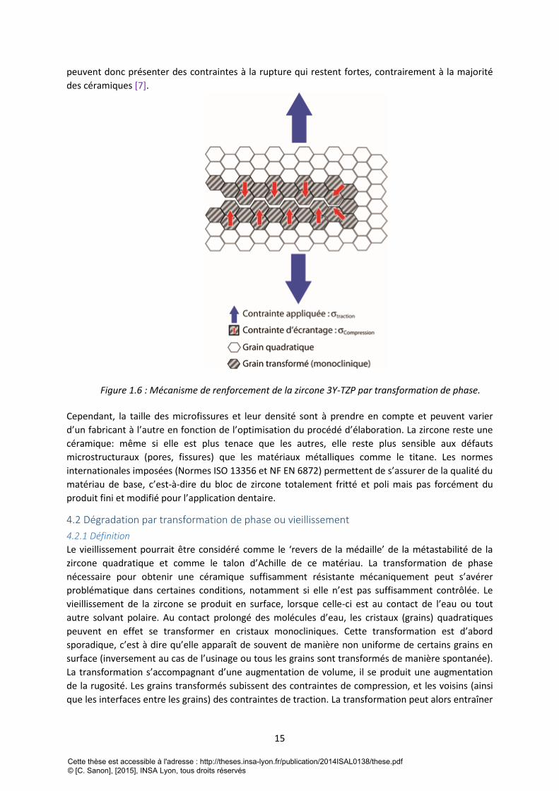
3. Structure cristalline de la zircone La cristallographie de la zircone évolue en fonction de la température. La phase stable de la zircone
pure, à basse température et jusqu’à 1170°C, est la phase monoclinique, trouvée dans la baddeleyite.
De 1170 à 2360°C, la structure cristalline est une phase quadratique (tetragonal en anglais) (Figure
1.5). Au-delà et jusqu’à son point de fusion, la zircone se présente selon une structure cubique
(fluorite). Dans le domaine des céramiques techniques, la recherche des meilleures propriétés
mécaniques restreint l’utilisation de la zircone dans sa phase quadratique. Pour retenir la structure
quadratique à température ambiante (on parle souvent de ‘stabiliser’ la zircone), il est possible
d’ajouter des oxydes de différentes natures. Les deux oxydes les plus utilisés sont l’oxyde d’yttrium
(Y2O3) et l’oxyde de cérium (CeO2). En odontologie, comme dans la plupart des applications cliniques
et industrielles, la zircone quadratique stabilisée par 3% mole d’oxyde d’yttrium (zircone 3Y-TZP) est
utilisée. Le terme de ‘stabilisation de la zircone’ par 3% molaire d’oxyde d’yttrium est un abus de
langage, car la zircone ainsi fabriquée est en fait métastable, maintenue à l’état quadratique à
température ambiante après élaboration, mais peut se transformer sous la forme stable,
monoclinique, lorsque des contraintes de tension très élevées lui sont appliquées [6].
Figure 1.5: Schéma des structures cristallographiques cubique, quadratique (ou tetragonal) et
monoclinique de la zircone, montrant la composante de cisaillement lors du passage de la forme
quadratique vers la forme monoclinique.
Cette thèse est accessible à l'adresse : http://theses.insa-lyon.fr/publication/2014ISAL0138/these.pdf © [C. Sanon], [2015], INSA Lyon, tous droits réservés
14
Structure cristalline Monoclinique Quadratique
Paramètres de mailles (Å)
a = 5,15 b = 5,21 c = 5,32
beta = 99,2°
a = 3,60 c = 5,18
Densité (g.cm-3) 5,8 6,09
Tableau 1.1 : Différence de paramètres entre la maille monoclinique et quadratique, expliquant
l’apparition des contraintes dans la zircone massive lors de la transformation de phase.
4. Transformation de phase de la zircone 3Y-TZP La transformation de phase de la structure quadratique vers la phase monoclinique s’accompagne
d’une composante de cisaillement, mais aussi d’une augmentation de volume significative de l’ordre
de 4% (tableau 1.1). La transformation est très rapide, quasi-instantanée (on parle de transformation
martensitique). Les différences dans les paramètres entre les structures quadratique et monoclinique
jouent un rôle essentiel dans le comportement du matériau car celui-ci est généralement utilisé sous
une forme massive très dense : le changement de forme d’un grain ou d’un groupe de grains, se
faisant par cisaillement et s’accompagnant d’une augmentation de volume, crée des contraintes dans
les grains transformés et leurs voisins
La zircone 3Y-TZP est donc métastable et tout apport d’énergie, toute contrainte peut la faire évoluer
vers son état stable, c’est-à-dire vers l’état monoclinique. Selon la nature des contraintes, les effets
sont différents et constituent une force (renforcement) ou une faiblesse (vieillissement) :
Si la contrainte est mécanique, il en résulte des effets de renforcement qui sont à l’origine
des remarquables propriétés mécaniques de la zircone 3Y-TZP,
Si la contrainte est hydro thermique (température et présence d’eau), c’est le phénomène de
dégradation à basse température qui se produit et qui est à l’origine du vieillissement de la
surface de la zircone [6].
4.1 Renforcement par transformation de phase Dans les blocs de zircone frittée, comme dans tout matériau massif, il y a des imperfections, des
défauts microscopiques inhérents à la fabrication, tels que des microfissures. Lorsque le matériau est
soumis à une contrainte, les zones défectueuses, les microfissures et plus particulièrement les zones
en fond de fissures deviennent des zones de concentration de contrainte. Si ces contraintes sont
suffisamment fortes localement, elles peuvent entraîner une propagation de fissure dans les
céramiques ‘classiques’. Dans le cas de la zircone, ces contraintes localement fortes entrainent aussi
une transformation des cristaux quadratiques situés au fond des fissures vers la forme monoclinique.
La transformation s’accompagnant d’une augmentation de volume, la transformation engendre des
contraintes de compression qui vont ralentir la propagation de la fissure. La transformation de phase
en fond de fissure conduit donc à une augmentation de la ténacité du matériau. Ce phénomène est à
l’origine des bonnes propriétés mécaniques (Figure 1.6). En effet, la zircone est la céramique de type
oxyde présentant la plus haute résistance à la rupture et la plus haute ténacité, grâce à cette
spécificité [2].
Une transformation de phase peut aussi avoir lieu en surface du matériau lors d’étapes d’usinage.
Les contraintes fortes que subit la céramique entrainent localement une transformation des grains,
une mise en compression de la surface et donc un renforcement du matériau. Les zircones usinées
Cette thèse est accessible à l'adresse : http://theses.insa-lyon.fr/publication/2014ISAL0138/these.pdf © [C. Sanon], [2015], INSA Lyon, tous droits réservés
15
peuvent donc présenter des contraintes à la rupture qui restent fortes, contrairement à la majorité
des céramiques [7].
Figure 1.6 : Mécanisme de renforcement de la zircone 3Y-TZP par transformation de phase.
Cependant, la taille des microfissures et leur densité sont à prendre en compte et peuvent varier
d’un fabricant à l’autre en fonction de l’optimisation du procédé d’élaboration. La zircone reste une
céramique: même si elle est plus tenace que les autres, elle reste plus sensible aux défauts
microstructuraux (pores, fissures) que les matériaux métalliques comme le titane. Les normes
internationales imposées (Normes ISO 13356 et NF EN 6872) permettent de s’assurer de la qualité du
matériau de base, c’est-à-dire du bloc de zircone totalement fritté et poli mais pas forcément du
produit fini et modifié pour l’application dentaire.
4.2 Dégradation par transformation de phase ou vieillissement
4.2.1 Définition
Le vieillissement pourrait être considéré comme le ‘revers de la médaille’ de la métastabilité de la
zircone quadratique et comme le talon d’Achille de ce matériau. La transformation de phase
nécessaire pour obtenir une céramique suffisamment résistante mécaniquement peut s’avérer
problématique dans certaines conditions, notamment si elle n’est pas suffisamment contrôlée. Le
vieillissement de la zircone se produit en surface, lorsque celle-ci est au contact de l’eau ou tout
autre solvant polaire. Au contact prolongé des molécules d’eau, les cristaux (grains) quadratiques
peuvent en effet se transformer en cristaux monocliniques. Cette transformation est d’abord
sporadique, c’est à dire qu’elle apparaît de souvent de manière non uniforme de certains grains en
surface (inversement au cas de l’usinage ou tous les grains sont transformés de manière spontanée).
La transformation s’accompagnant d’une augmentation de volume, il se produit une augmentation
de la rugosité. Les grains transformés subissent des contraintes de compression, et les voisins (ainsi
que les interfaces entre les grains) des contraintes de traction. La transformation peut alors entraîner
Cette thèse est accessible à l'adresse : http://theses.insa-lyon.fr/publication/2014ISAL0138/these.pdf © [C. Sanon], [2015], INSA Lyon, tous droits réservés
16
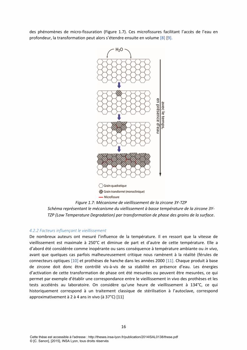
des phénomènes de micro-fissuration (Figure 1.7). Ces microfissures facilitant l’accès de l’eau en
profondeur, la transformation peut alors s’étendre ensuite en volume [8] [9].
Figure 1.7: Mécanisme de vieillissement de la zircone 3Y-TZP
Schéma représentant le mécanisme du viellissement à basse température de la zircone 3Y-
TZP (Low Temperature Degradation) par transformation de phase des grains de la surface.
4.2.2 Facteurs influençant le vieillissement
De nombreux auteurs ont mesuré l’influence de la température. Il en ressort que la vitesse de
vieillissement est maximale à 250°C et diminue de part et d’autre de cette température. Elle a
d’abord été considérée comme inopérante ou sans conséquence à température ambiante ou in vivo,
avant que quelques cas parfois malheureusement critique nous ramènent à la réalité (férules de
connecteurs optiques [10] et prothèses de hanche dans les années 2000 [11]. Chaque produit à base
de zircone doit donc être contrôlé vis-à-vis de sa stabilité en présence d’eau. Les énergies
d’activation de cette transformation de phase ont été mesurées ou peuvent être mesurées, ce qui
permet par exemple d’établir une correspondance entre le vieillissement in vivo des prothèses et les
tests accélérés au laboratoire. On considère qu’une heure de vieillissement à 134°C, ce qui
historiquement correspond à un traitement classique de stérilisation à l’autoclave, correspond
approximativement à 2 à 4 ans in vivo (à 37°C) [11]
Cette thèse est accessible à l'adresse : http://theses.insa-lyon.fr/publication/2014ISAL0138/these.pdf © [C. Sanon], [2015], INSA Lyon, tous droits réservés
17
La microstructure résultante du procédé d’élaboration influence grandement la cinétique de
vieillissement. Nous savons aujourd’hui que la taille des grains, l’homogénéité de la microstructure
ainsi que l’état de surface jouent un rôle prépondérant sur la vitesse de vieillissement [12, 13].
Pour leurs applications dentaires, la plupart des produits disponibles en zircone 3Y-TZP subissent un
ou plusieurs traitements de surfaces par exemple, les infrastructures pour couronnes sont souvent
traitées sablage par le prothésiste pour améliorer la liaison avec la céramique cosmétique et le
collage aux tissus dentaires ou aux autres pièces prothétiques. Les implants dentaires en zircone 3Y-
TZP sont aussi sujets au traitement de surface pour améliorer l’ostéointégration. Ces modifications
de surface peuvent modifier le comportement à long terme de la zircone et doivent être contrôlées.
De simples essais de vieillissement accélérés en autoclave sur les surfaces représentatives devraient
être réalisés systématiquement pour valider chaque traitement de surface, alors que la norme ISO
13356 ne l’impose pas [14].
5. Propriétés de la zircone 3Y-TZP
Les propriétés physiques, thermiques, chimiques et mécaniques des matériaux sont toujours reliées
à la nature des liaisons interatomiques et à leur arrangement cristallographique. Les liaisons
interatomiques dans la zircone sont des liaisons fortes, de type plutôt ionique. Ces liaisons
impliquent tous les électrons de valence des atomes, c’est-à-dire des électrons fortement liés au
réseau ce qui se traduit par un certains nombres de caractéristiques retrouvées dans les céramiques
massives.
D’un point de vue mécanique, ces liaisons fortes entrainent une rigidité importante, une dureté
élevées, et une résistance à la rupture dissymétrique en fonction du type de contraintes appliquées:
les céramiques résistent mieux en compression qu’en traction [15].
5.1 Propriétés mécaniques
5.1.1 Rigidité et plasticité
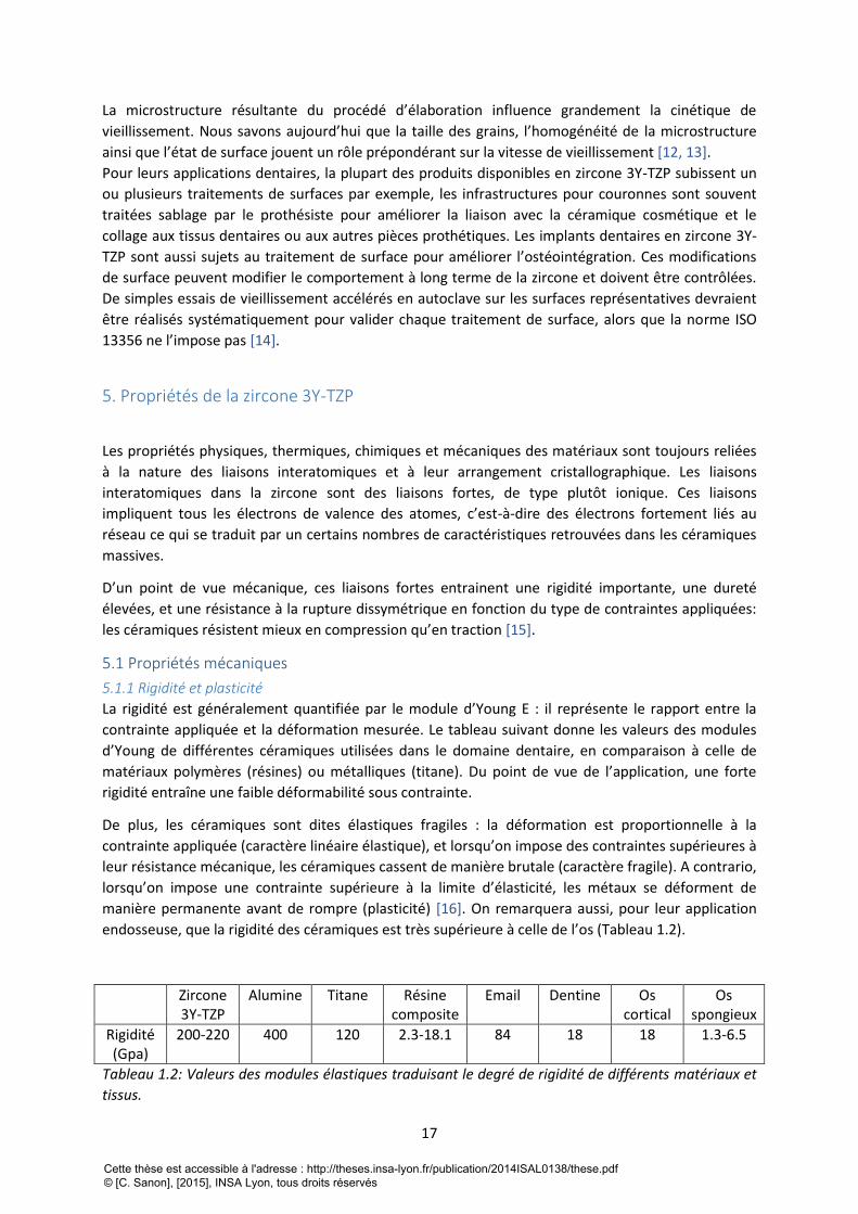
La rigidité est généralement quantifiée par le module d’Young E : il représente le rapport entre la
contrainte appliquée et la déformation mesurée. Le tableau suivant donne les valeurs des modules
d’Young de différentes céramiques utilisées dans le domaine dentaire, en comparaison à celle de
matériaux polymères (résines) ou métalliques (titane). Du point de vue de l’application, une forte
rigidité entraîne une faible déformabilité sous contrainte.
De plus, les céramiques sont dites élastiques fragiles : la déformation est proportionnelle à la
contrainte appliquée (caractère linéaire élastique), et lorsqu’on impose des contraintes supérieures à
leur résistance mécanique, les céramiques cassent de manière brutale (caractère fragile). A contrario,
lorsqu’on impose une contrainte supérieure à la limite d’élasticité, les métaux se déforment de
manière permanente avant de rompre (plasticité) [16]. On remarquera aussi, pour leur application
endosseuse, que la rigidité des céramiques est très supérieure à celle de l’os (Tableau 1.2).
Zircone 3Y-TZP
Alumine Titane Résine composite
Email Dentine Os cortical
Os spongieux
Rigidité (Gpa)
200-220 400 120 2.3-18.1 84 18 18 1.3-6.5
Tableau 1.2: Valeurs des modules élastiques traduisant le degré de rigidité de différents matériaux et
tissus.
Cette thèse est accessible à l'adresse : http://theses.insa-lyon.fr/publication/2014ISAL0138/these.pdf © [C. Sanon], [2015], INSA Lyon, tous droits réservés
18
5.1.2 Une dureté élevée
Une dureté élevée traduit une forte résistance à l’abrasion, ce qui est souvent un avantage (peu
d’usure). Dans le cas d’une application dentaire, il faudra cependant veiller à l’équilibre des contacts
occlusaux afin de ne pas endommager la dent antagoniste.
5.1.3 Résistance à la rupture dissymétrique
De façon générale, les céramiques sont bien plus résistantes en compression qu’en traction. On
considère qu’il y a un facteur 10 environ entre les valeurs de contraintes maximales admissible en
compression et en traction. Aussi, on cherche généralement à minimiser les zones sujettes à de la
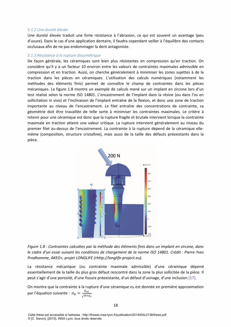
traction dans les pièces en céramiques. L’utilisation des calculs numériques (notamment les
méthodes des éléments finis) permet de connaître le champ de contraintes dans les pièces
mécaniques. La figure 1.8 montre un exemple de calculs mené sur un implant en zircone lors d’un
test réalisé selon la norme ISO 14801. L’encastrement de l’implant dans la résine (ou dans l’os en
sollicitation in vivo) et l’inclinaison de l’implant entraîne de la flexion, et donc une zone de traction
importante au niveau de l’encastrement. Le filet entraîne des concentrations de contrainte, sa
géométrie doit être travaillée de telle sorte à minimiser les contraintes maximales. Le critère à
retenir pour une céramique est donc que la rupture fragile et brutale intervient lorsque la contrainte
maximale en traction atteint une valeur critique. La rupture intervient généralement au niveau du
premier filet au-dessus de l’encastrement. La contrainte à la rupture dépend de la céramique elle-
même (composition, structure cristalline), mais aussi de la taille des défauts préexistants dans la
pièce.
Figure 1.8 : Contraintes calculées par la méthode des éléments finis dans un implant en zircone, dans
le cadre d’un essai suivant les conditions de chargement de la norme ISO 14801. Crédit : Pierre-Yves
Prodhomme, AKEO+, projet LONGLIFE (rhttp://longlife-project.eu).
La résistance mécanique (ou contrainte maximale admissible) d’une céramique dépend
essentiellement de la taille du plus gros défaut rencontré dans la zone la plus sollicitée de la pièce. Il
peut s’agir d’une porosité, d’une fissure préexistante, d’un défaut d’usinage, d’une inclusion [17].
On montre que la contrainte à la rupture d’une céramique R est donnée en première approximation
par l’équation suivante : 𝜎𝑅 =𝐾𝐼𝐶
√𝜋×𝑎𝑐
Cette thèse est accessible à l'adresse : http://theses.insa-lyon.fr/publication/2014ISAL0138/these.pdf © [C. Sanon], [2015], INSA Lyon, tous droits réservés
19
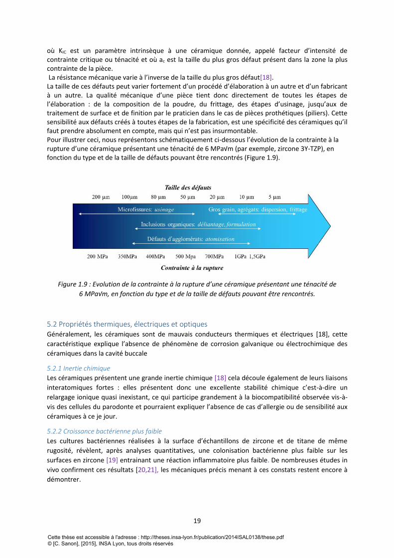
où KIC est un paramètre intrinsèque à une céramique donnée, appelé facteur d’intensité de contrainte critique ou ténacité et où ac est la taille du plus gros défaut présent dans la zone la plus contrainte de la pièce. La résistance mécanique varie à l’inverse de la taille du plus gros défaut[18]. La taille de ces défauts peut varier fortement d’un procédé d’élaboration à un autre et d’un fabricant à un autre. La qualité mécanique d’une pièce tient donc directement de toutes les étapes de l’élaboration : de la composition de la poudre, du frittage, des étapes d’usinage, jusqu’aux de traitement de surface et de finition par le praticien dans le cas de pièces prothétiques (piliers). Cette sensibilité aux défauts créés à toutes étapes de la fabrication, est une spécificité des céramiques qu’il faut prendre absolument en compte, mais qui n’est pas insurmontable. Pour illustrer ceci, nous représentons schématiquement ci-dessous l’évolution de la contrainte à la rupture d’une céramique présentant une ténacité de 6 MPa√m (par exemple, zircone 3Y-TZP), en fonction du type et de la taille de défauts pouvant être rencontrés (Figure 1.9).
Figure 1.9 : Evolution de la contrainte à la rupture d’une céramique présentant une ténacité de
6 MPa√m, en fonction du type et de la taille de défauts pouvant être rencontrés.
5.2 Propriétés thermiques, électriques et optiques Généralement, les céramiques sont de mauvais conducteurs thermiques et électriques [18], cette
caractéristique explique l’absence de phénomène de corrosion galvanique ou électrochimique des
céramiques dans la cavité buccale
5.2.1 Inertie chimique
Les céramiques présentent une grande inertie chimique [18] cela découle également de leurs liaisons
interatomiques fortes : elles présentent donc une excellente stabilité chimique c’est-à-dire un
relargage ionique quasi inexistant, ce qui participe grandement à la biocompatibilité observée vis-à-
vis des cellules du parodonte et pourraient expliquer l’absence de cas d’allergie ou de sensibilité aux
céramiques à ce je jour.
5.2.2 Croissance bactérienne plus faible
Les cultures bactériennes réalisées à la surface d’échantillons de zircone et de titane de même
rugosité, révèlent, après analyses quantitatives, une colonisation bactérienne plus faible sur les
surfaces en zircone [19] entrainant une réaction inflammatoire plus faible. De nombreuses études in
vivo confirment ces résultats [20,21], les mécaniques précis menant à ces constats restent encore à
démontrer.
Cette thèse est accessible à l'adresse : http://theses.insa-lyon.fr/publication/2014ISAL0138/these.pdf © [C. Sanon], [2015], INSA Lyon, tous droits réservés
20
5.2.3 Aspect esthétique
Du fait de sa couleur blanche, la zircone s’intègre totalement dans la sphère buccale. De plus, la
zircone peut être colorée et certains fabricants (Straumann, CIM implant®) proposent des teintes
parfaitement adaptée à l’environnement tissulaire ce qui permet l’obtention d’un résultat esthétique
quel que soit le biotype parodontal. Ce n’est pas toujours le cas avec les implants en titane. En
revanche, les effets de la coloration sur les propriétés de durabilité de la zircone sont encore mal
connus et peu étudiés.
6. La zircone 3Y-TZP en implantologie orale
6.1 Généralités Du fait de son aspect esthétique, de sa résistance mécanique supérieure aux autres céramiques et de
sa biocompatibilité, la zircone 3Y-TZP a été placée comme la « céramique favorite » pour
l’implantologie. Elle est même perçue par certains comme l’alternative au titane. En effet, le titane
peut trouver ses limites d’un point de vue esthétique lorsque les conditions mucco-gingivales ne sont
pas optimales, c’est-à-dire : lorsque les tissus péri-implantaires sont fins, la couleur grise du métal
peut transparaître à travers ces tissus et donner un aspect inesthétique au sourire, d’autant plus
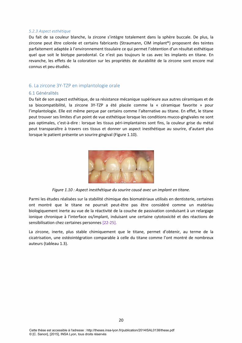
lorsque le patient présente un sourire gingival (Figure 1.10).
Figure 1.10 : Aspect inesthétique du sourire causé avec un implant en titane.
Parmi les études réalisées sur la stabilité chimique des biomatériaux utilisés en dentisterie, certaines
ont montré que le titane ne pourrait peut-être pas être considéré comme un matériau
biologiquement inerte au vue de la réactivité de la couche de passivation conduisant à un relargage
ionique chronique à l’interface os/implant, induisant une certaine cytotoxicité et des réactions de
sensibilisation chez certaines personnes [22-25].
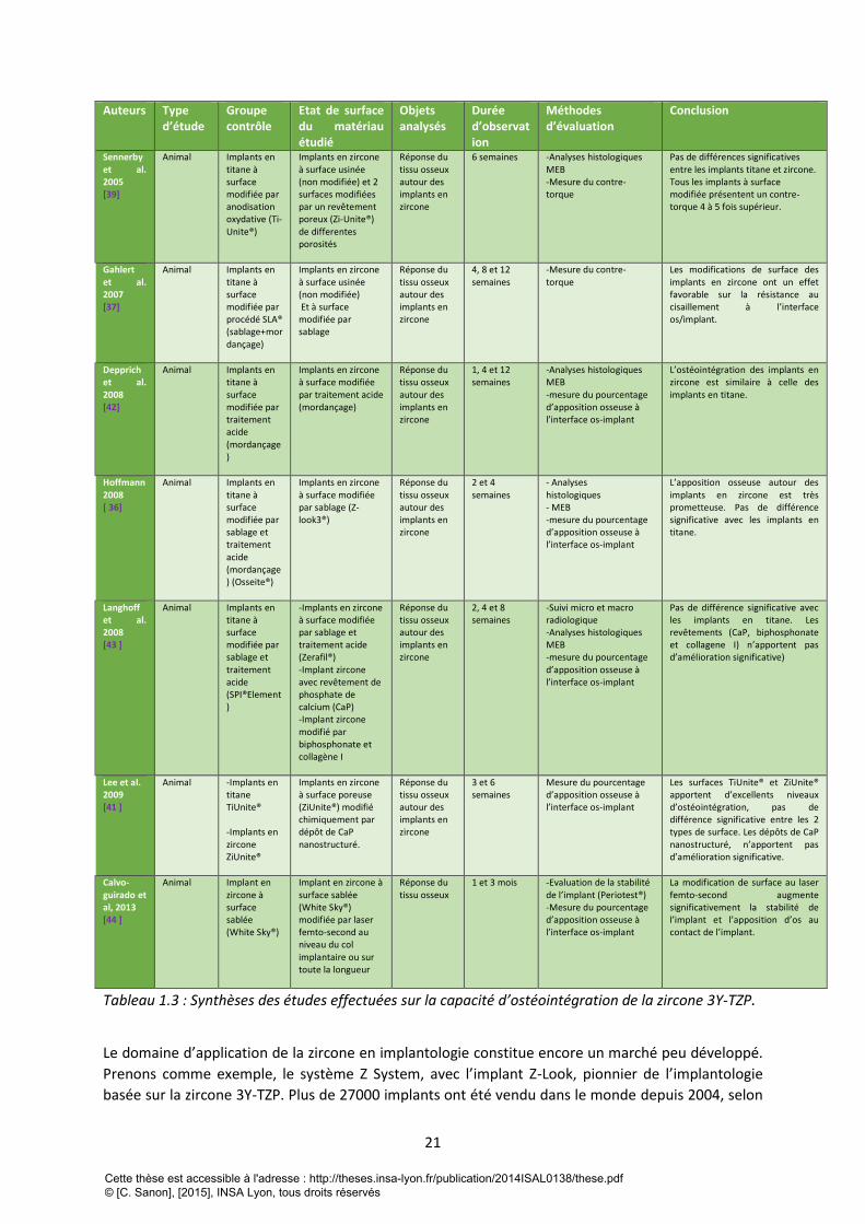
La zircone, inerte, plus stable chimiquement que le titane, permet d’obtenir, au terme de la
cicatrisation, une ostéointégration comparable à celle du titane comme l’ont montré de nombreux
auteurs (tableau 1.3).
Cette thèse est accessible à l'adresse : http://theses.insa-lyon.fr/publication/2014ISAL0138/these.pdf © [C. Sanon], [2015], INSA Lyon, tous droits réservés
21
Auteurs Type d’étude
Groupe contrôle
Etat de surface du matériau étudié
Objets analysés
Durée d’observation
Méthodes d’évaluation
Conclusion
Sennerby et al. 2005 [39]
Animal Implants en titane à surface modifiée par anodisation oxydative (Ti-Unite®)
Implants en zircone à surface usinée (non modifiée) et 2 surfaces modifiées par un revêtement poreux (Zi-Unite®) de differentes porosités
Réponse du tissu osseux autour des implants en zircone
6 semaines -Analyses histologiques MEB -Mesure du contre-torque
Pas de différences significatives entre les implants titane et zircone. Tous les implants à surface modifiée présentent un contre-torque 4 à 5 fois supérieur.
Gahlert et al. 2007 [37]
Animal Implants en titane à surface modifiée par procédé SLA® (sablage+mordançage)
Implants en zircone à surface usinée (non modifiée) Et à surface modifiée par sablage
Réponse du tissu osseux autour des implants en zircone
4, 8 et 12 semaines
-Mesure du contre-torque
Les modifications de surface des implants en zircone ont un effet favorable sur la résistance au cisaillement à l’interface os/implant.
Depprich et al. 2008 [42]
Animal Implants en titane à surface modifiée par traitement acide (mordançage)
Implants en zircone à surface modifiée par traitement acide (mordançage)
Réponse du tissu osseux autour des implants en zircone
1, 4 et 12 semaines
-Analyses histologiques MEB -mesure du pourcentage d’apposition osseuse à l’interface os-implant
L’ostéointégration des implants en zircone est similaire à celle des implants en titane.
Hoffmann 2008 [ 36]
Animal Implants en titane à surface modifiée par sablage et traitement acide (mordançage) (Osseite®)
Implants en zircone à surface modifiée par sablage (Z-look3®)
Réponse du tissu osseux autour des implants en zircone
2 et 4 semaines
- Analyses histologiques - MEB -mesure du pourcentage d’apposition osseuse à l’interface os-implant
L’apposition osseuse autour des implants en zircone est très prometteuse. Pas de différence significative avec les implants en titane.
Langhoff et al. 2008 [43 ]
Animal Implants en titane à surface modifiée par sablage et traitement acide (SPI®Element)
-Implants en zircone à surface modifiée par sablage et traitement acide (Zerafil®) -Implant zircone avec revêtement de phosphate de calcium (CaP) -Implant zircone modifié par biphosphonate et collagène I
Réponse du tissu osseux autour des implants en zircone
2, 4 et 8 semaines
-Suivi micro et macro radiologique -Analyses histologiques MEB -mesure du pourcentage d’apposition osseuse à l’interface os-implant
Pas de différence significative avec les implants en titane. Les revêtements (CaP, biphosphonate et collagene I) n’apportent pas d’amélioration significative)
Lee et al. 2009 [41 ]
Animal -Implants en titane TiUnite® -Implants en zircone ZiUnite®
Implants en zircone à surface poreuse (ZiUnite®) modifié chimiquement par dépôt de CaP nanostructuré.
Réponse du tissu osseux autour des implants en zircone
3 et 6 semaines
Mesure du pourcentage d’apposition osseuse à l’interface os-implant
Les surfaces TiUnite® et ZiUnite® apportent d’excellents niveaux d’ostéointégration, pas de différence significative entre les 2 types de surface. Les dépôts de CaP nanostructuré, n’apportent pas d’amélioration significative.
Calvo-guirado et al, 2013 [44 ]
Animal Implant en zircone à surface sablée (White Sky®)
Implant en zircone à surface sablée (White Sky®) modifiée par laser femto-second au niveau du col implantaire ou sur toute la longueur
Réponse du tissu osseux
1 et 3 mois -Evaluation de la stabilité de l’implant (Periotest®) -Mesure du pourcentage d’apposition osseuse à l’interface os-implant
La modification de surface au laser femto-second augmente significativement la stabilité de l’implant et l’apposition d’os au contact de l’implant.
Tableau 1.3 : Synthèses des études effectuées sur la capacité d’ostéointégration de la zircone 3Y-TZP.
Le domaine d’application de la zircone en implantologie constitue encore un marché peu développé.
Prenons comme exemple, le système Z System, avec l’implant Z-Look, pionnier de l’implantologie
basée sur la zircone 3Y-TZP. Plus de 27000 implants ont été vendu dans le monde depuis 2004, selon
Cette thèse est accessible à l'adresse : http://theses.insa-lyon.fr/publication/2014ISAL0138/these.pdf © [C. Sanon], [2015], INSA Lyon, tous droits réservés
22
le fabricant. Ces chiffres sont à mettre en relations avec les 1,7 millions d’implants en titane posés en
2007 aux Etats-Unis [26].
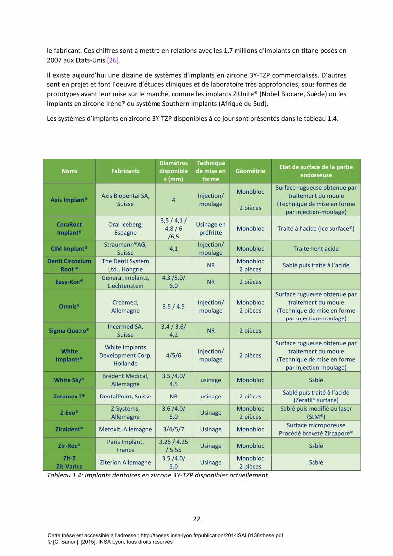
Il existe aujourd’hui une dizaine de systèmes d’implants en zircone 3Y-TZP commercialisés. D’autres
sont en projet et font l’oeuvre d’études cliniques et de laboratoire très approfondies, sous formes de
prototypes avant leur mise sur le marché, comme les implants ZiUnite® (Nobel Biocare, Suède) ou les
implants en zircone Irène® du système Southern Implants (Afrique du Sud).
Les systèmes d’implants en zircone 3Y-TZP disponibles à ce jour sont présentés dans le tableau 1.4.
Noms Fabricants Diamètres disponible
s (mm)
Technique de mise en
forme Géométrie
Etat de surface de la partie endosseuse
Axis Implant® Axis Biodental SA,
Suisse 4
Injection/ moulage
Monobloc
2 pièces
Surface rugueuse obtenue par traitement du moule
(Technique de mise en forme par injection-moulage)
CeraRoot Implant®
Oral Iceberg, Espagne
3,5 / 4,1 / 4,8 / 6
/6,5
Usinage en préfritté
Monobloc Traité à l’acide (Ice surface®)
CIM Implant® Straumann®AG,
Suisse 4,1
Injection/ moulage
Monobloc Traitement acide
Denti Circonium Root ®
The Denti System Ltd., Hongrie
NR Monobloc 2 pièces
Sablé puis traité à l’acide
Easy-Kon® General Implants,
Liechtenstein 4.3 /5.0/
6.0 NR 2 pièces
Omnis® Creamed, Allemagne
3.5 / 4.5 Injection/ moulage
Monobloc 2 pièces
Surface rugueuse obtenue par traitement du moule
(Technique de mise en forme par injection-moulage)
Sigma Quatro® Incermed SA,
Suisse 3,4 / 3,6/
4,2 NR 2 pièces
White Implants®
White Implants Development Corp,
Hollande 4/5/6
Injection/ moulage
2 pièces
Surface rugueuse obtenue par traitement du moule
(Technique de mise en forme par injection-moulage)
White Sky® Bredent Medical,
Allemagne 3.5 /4.0/
4.5 usinage Monobloc Sablé
Zeramex T® DentalPoint, Suisse NR usinage 2 pièces Sablé puis traité à l’acide
(Zerafil® surface)
Z-Evo® Z-Systems, Allemagne
3.6 /4.0/ 5.0
Usinage Monobloc 2 pièces
Sablé puis modifié au laser (SLM®)
Ziraldent® Metoxit, Allemagne 3/4/5/7 Usinage Monobloc Surface microporeuse
Procédé breveté Zircapore®
Zir-Roc® Paris Implant,
France 3.25 / 4.25
/ 5.55 Usinage Monobloc Sablé
Zit-Z Zit-Varioz
Ziterion Allemagne 3.5 /4.0/
5.0 Usinage
Monobloc 2 pièces
Sablé
Tableau 1.4: Implants dentaires en zircone 3Y-TZP disponibles actuellement.
Cette thèse est accessible à l'adresse : http://theses.insa-lyon.fr/publication/2014ISAL0138/these.pdf © [C. Sanon], [2015], INSA Lyon, tous droits réservés
23
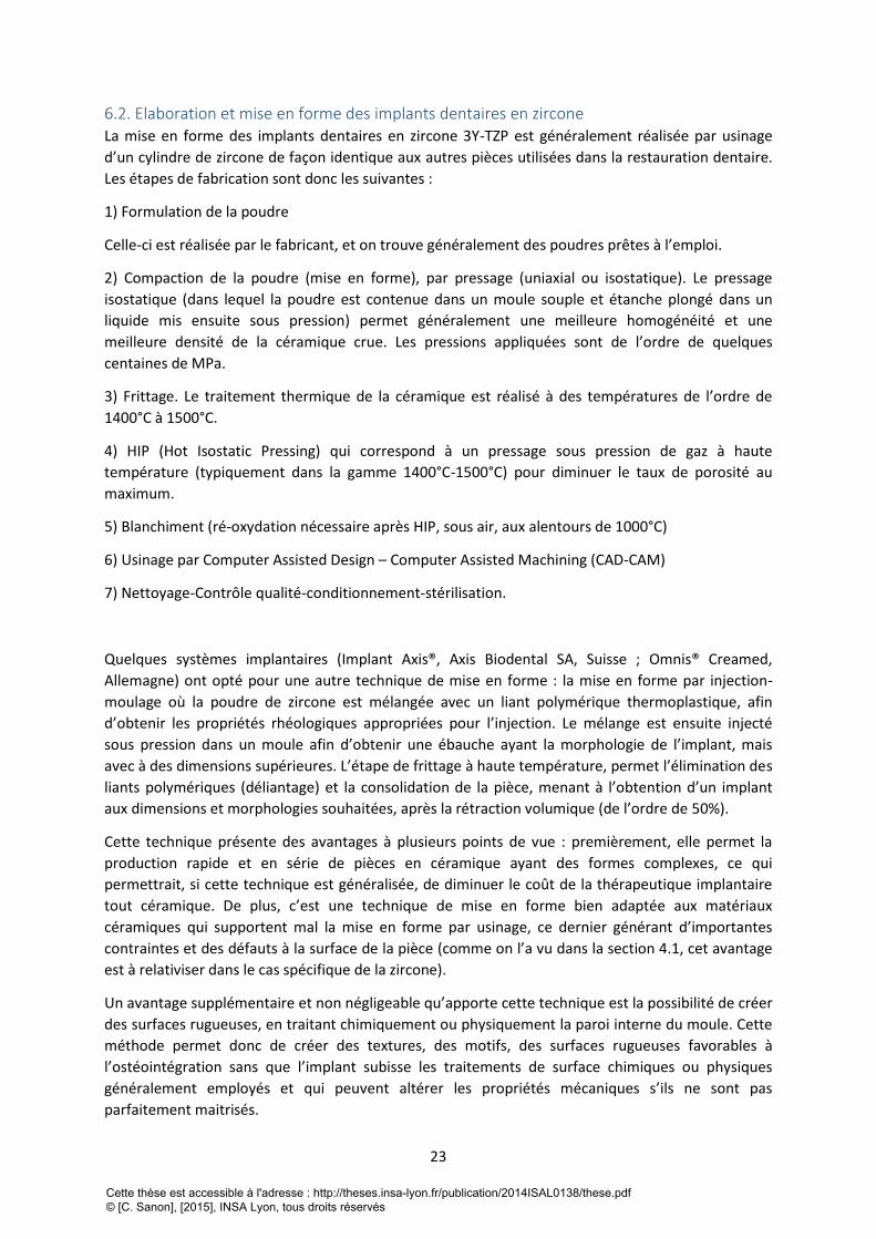
6.2. Elaboration et mise en forme des implants dentaires en zircone La mise en forme des implants dentaires en zircone 3Y-TZP est généralement réalisée par usinage
d’un cylindre de zircone de façon identique aux autres pièces utilisées dans la restauration dentaire.
Les étapes de fabrication sont donc les suivantes :
1) Formulation de la poudre
Celle-ci est réalisée par le fabricant, et on trouve généralement des poudres prêtes à l’emploi.
2) Compaction de la poudre (mise en forme), par pressage (uniaxial ou isostatique). Le pressage
isostatique (dans lequel la poudre est contenue dans un moule souple et étanche plongé dans un
liquide mis ensuite sous pression) permet généralement une meilleure homogénéité et une
meilleure densité de la céramique crue. Les pressions appliquées sont de l’ordre de quelques
centaines de MPa.
3) Frittage. Le traitement thermique de la céramique est réalisé à des températures de l’ordre de
1400°C à 1500°C.
4) HIP (Hot Isostatic Pressing) qui correspond à un pressage sous pression de gaz à haute
température (typiquement dans la gamme 1400°C-1500°C) pour diminuer le taux de porosité au
maximum.
5) Blanchiment (ré-oxydation nécessaire après HIP, sous air, aux alentours de 1000°C)
6) Usinage par Computer Assisted Design – Computer Assisted Machining (CAD-CAM)
7) Nettoyage-Contrôle qualité-conditionnement-stérilisation.
Quelques systèmes implantaires (Implant Axis®, Axis Biodental SA, Suisse ; Omnis® Creamed,
Allemagne) ont opté pour une autre technique de mise en forme : la mise en forme par injection-
moulage où la poudre de zircone est mélangée avec un liant polymérique thermoplastique, afin
d’obtenir les propriétés rhéologiques appropriées pour l’injection. Le mélange est ensuite injecté
sous pression dans un moule afin d’obtenir une ébauche ayant la morphologie de l’implant, mais
avec à des dimensions supérieures. L’étape de frittage à haute température, permet l’élimination des
liants polymériques (déliantage) et la consolidation de la pièce, menant à l’obtention d’un implant
aux dimensions et morphologies souhaitées, après la rétraction volumique (de l’ordre de 50%).
Cette technique présente des avantages à plusieurs points de vue : premièrement, elle permet la
production rapide et en série de pièces en céramique ayant des formes complexes, ce qui
permettrait, si cette technique est généralisée, de diminuer le coût de la thérapeutique implantaire
tout céramique. De plus, c’est une technique de mise en forme bien adaptée aux matériaux
céramiques qui supportent mal la mise en forme par usinage, ce dernier générant d’importantes
contraintes et des défauts à la surface de la pièce (comme on l’a vu dans la section 4.1, cet avantage
est à relativiser dans le cas spécifique de la zircone).
Un avantage supplémentaire et non négligeable qu’apporte cette technique est la possibilité de créer
des surfaces rugueuses, en traitant chimiquement ou physiquement la paroi interne du moule. Cette
méthode permet donc de créer des textures, des motifs, des surfaces rugueuses favorables à
l’ostéointégration sans que l’implant subisse les traitements de surface chimiques ou physiques
généralement employés et qui peuvent altérer les propriétés mécaniques s’ils ne sont pas
parfaitement maitrisés.
Cette thèse est accessible à l'adresse : http://theses.insa-lyon.fr/publication/2014ISAL0138/these.pdf © [C. Sanon], [2015], INSA Lyon, tous droits réservés
24
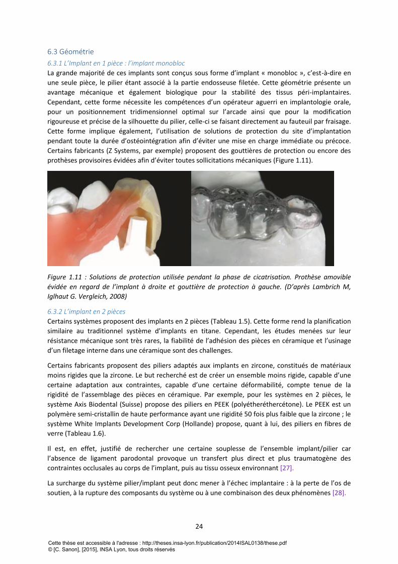
6.3 Géométrie
6.3.1 L’Implant en 1 pièce : l’implant monobloc
La grande majorité de ces implants sont conçus sous forme d’implant « monobloc », c’est-à-dire en
une seule pièce, le pilier étant associé à la partie endosseuse filetée. Cette géométrie présente un
avantage mécanique et également biologique pour la stabilité des tissus péri-implantaires.
Cependant, cette forme nécessite les compétences d’un opérateur aguerri en implantologie orale,
pour un positionnement tridimensionnel optimal sur l’arcade ainsi que pour la modification
rigoureuse et précise de la silhouette du pilier, celle-ci se faisant directement au fauteuil par fraisage.
Cette forme implique également, l’utilisation de solutions de protection du site d’implantation
pendant toute la durée d’ostéointégration afin d’éviter une mise en charge immédiate ou précoce.
Certains fabricants (Z Systems, par exemple) proposent des gouttières de protection ou encore des
prothèses provisoires évidées afin d’éviter toutes sollicitations mécaniques (Figure 1.11).
Figure 1.11 : Solutions de protection utilisée pendant la phase de cicatrisation. Prothèse amovible
évidée en regard de l’implant à droite et gouttière de protection à gauche. (D’après Lambrich M,
Iglhaut G. Vergleich, 2008)
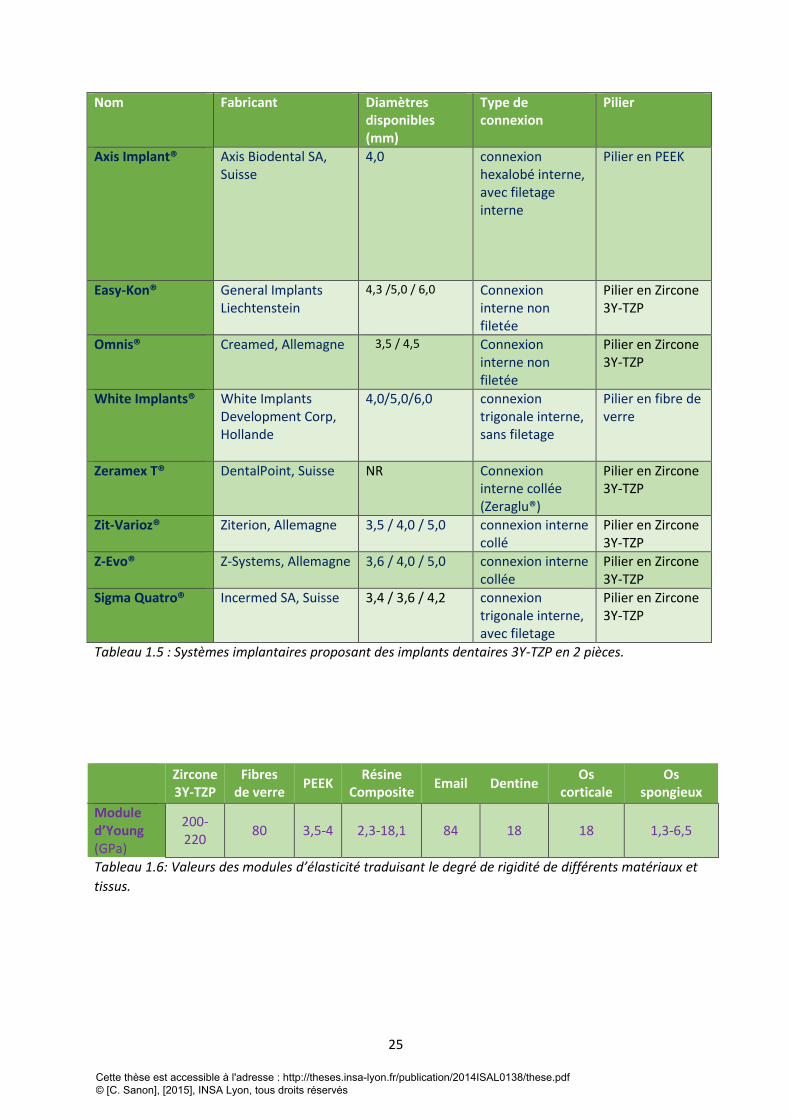
6.3.2 L’implant en 2 pièces
Certains systèmes proposent des implants en 2 pièces (Tableau 1.5). Cette forme rend la planification
similaire au traditionnel système d’implants en titane. Cependant, les études menées sur leur
résistance mécanique sont très rares, la fiabilité de l’adhésion des pièces en céramique et l’usinage
d’un filetage interne dans une céramique sont des challenges.
Certains fabricants proposent des piliers adaptés aux implants en zircone, constitués de matériaux
moins rigides que la zircone. Le but recherché est de créer un ensemble moins rigide, capable d’une
certaine adaptation aux contraintes, capable d’une certaine déformabilité, compte tenue de la
rigidité de l’assemblage des pièces en céramique. Par exemple, pour les systèmes en 2 pièces, le
système Axis Biodental (Suisse) propose des piliers en PEEK (polyétheréthercétone). Le PEEK est un
polymère semi-cristallin de haute performance ayant une rigidité 50 fois plus faible que la zircone ; le
système White Implants Development Corp (Hollande) propose, quant à lui, des piliers en fibres de
verre (Tableau 1.6).
Il est, en effet, justifié de rechercher une certaine souplesse de l’ensemble implant/pilier car
l’absence de ligament parodontal provoque un transfert plus direct et plus traumatogène des
contraintes occlusales au corps de l’implant, puis au tissu osseux environnant [27].
La surcharge du système pilier/implant peut donc mener à l’échec implantaire : à la perte de l’os de
soutien, à la rupture des composants du système ou à une combinaison des deux phénomènes [28].
Cette thèse est accessible à l'adresse : http://theses.insa-lyon.fr/publication/2014ISAL0138/these.pdf © [C. Sanon], [2015], INSA Lyon, tous droits réservés
25
Nom Fabricant Diamètres disponibles (mm)
Type de connexion
Pilier
Axis Implant® Axis Biodental SA, Suisse
4,0 connexion hexalobé interne, avec filetage interne
Pilier en PEEK
Easy-Kon® General Implants Liechtenstein
4,3 /5,0 / 6,0 Connexion interne non filetée
Pilier en Zircone 3Y-TZP
Omnis® Creamed, Allemagne 3,5 / 4,5
Connexion interne non filetée
Pilier en Zircone 3Y-TZP
White Implants® White Implants Development Corp, Hollande
4,0/5,0/6,0 connexion trigonale interne, sans filetage
Pilier en fibre de verre
Zeramex T® DentalPoint, Suisse NR Connexion interne collée (Zeraglu®)
Pilier en Zircone 3Y-TZP
Zit-Varioz® Ziterion, Allemagne 3,5 / 4,0 / 5,0 connexion interne collé
Pilier en Zircone 3Y-TZP
Z-Evo® Z-Systems, Allemagne 3,6 / 4,0 / 5,0 connexion interne collée
Pilier en Zircone 3Y-TZP
Sigma Quatro® Incermed SA, Suisse 3,4 / 3,6 / 4,2 connexion trigonale interne, avec filetage
Pilier en Zircone 3Y-TZP
Tableau 1.5 : Systèmes implantaires proposant des implants dentaires 3Y-TZP en 2 pièces.
Zircone 3Y-TZP
Fibres de verre
PEEK Résine
Composite Email Dentine
Os corticale
Os spongieux
Module d’Young (GPa)
200-220
80 3,5-4 2,3-18,1 84 18 18 1,3-6,5
Tableau 1.6: Valeurs des modules d’élasticité traduisant le degré de rigidité de différents matériaux et
tissus.
Cette thèse est accessible à l'adresse : http://theses.insa-lyon.fr/publication/2014ISAL0138/these.pdf © [C. Sanon], [2015], INSA Lyon, tous droits réservés
26
7. Comportement des implants en zircone 3Y-TZP dans l’environnement biologique à
court terme
7.1 Réactions d’adsorption La zircone, et le titane pur ou allié, implantés dans l’os, sont capables d’interagir avec les tissus
environnants grâce à des mécanismes d’adsorption qui se produisent dès les premières minutes.
C’est par leur couche de passivation, constituée majoritairement de dioxyde de titane, que les
implants en titane interagissent avec les éléments de la matrice extracellulaire. La zircone, elle, est
entièrement constituée d’oxydes (oxyde de zirconium), et possède également cette capacité
d’interagir avec les éléments de la matrice extracellulaire par un phénomène d’adsorption :
adsorption d’eau, d’ions et de protéines.
7.2 Adsorption d’eau et d’ions de la matrice extracellulaire L’adsorption d’eau à la surface de la zircone, spécifiquement sur certains types cristallographiques de
surfaces, conduit à la formation de radicaux hydroxyles (R-OH) en surface [28] ce qui peut favoriser
dans un deuxième temps l’adsorption d’ions calcium et phosphate. Lors de tests in vitro, il est
montré que ces ions se concentrent en surface, précipitent en phosphate de calcium puis
s’organisent sous forme d’apatite similaire à celle du minéral osseux. La croissance de l’apatite en
surface, n’est pas un phénomène exclusif aux oxydes de titane et de zirconium. En effet, tous les
oxydes forment des groupements hydroxyle en surface lorsqu’ils sont immergés dans un milieu
aqueux [29,30].
7.3 Adsorption de protéines de la matrice extracellulaire Par la suite, des protéines telles que l’ostéocalcine, l’ostéopontine, la sialoprotéine osseuse et la
fibronectine sont également adsorbées à la surface du matériau, elles influent sur la croissance
cristalline de l’apatite et sur l’adhésion des ostéoblastes à la surface implantaire. Par exemple,
l’ostéopontine favorise la cohésion entre le tissu et l’implant, tandis que la sialoprotéine osseuse
favorise la nucléation du minéral osseux [31-34].
7.4 Réactions d’adhésion cellulaire De nombreuses études ont mis en évidence la capacité d’adhésion, de prolifération et de
différenciation des cellules ostéoblastiques à la surface de la zircone, ceci par la formation de contact
focaux et de façon similaire aux implants en titane [35].
Par ailleurs, des cultures bactériennes réalisées à la surface d’échantillons de zircone et de titane de
même rugosité, révèlent, après analyses quantitatives, une colonisation bactérienne plus faible sur
les surfaces en zircone [19]. De nombreuses études in vivo confirment ces résultats [20,21].
7.5 Réaction tissulaire : l’ostéointégration Les essais in vivo, sur différents modèles animaux, ont permis de valider la capacité
d’ostéointégration de la zircone après l’implantation dans un tissus osseux. Ce phénomène a été
évalué de façon qualitative d’une part, par des analyses microscopiques de coupes histologiques [35-
37] et d’autre part, de façon quantitative, par mesure de l’ancrage mécanique et plus précisément du
contre-torque après un temps déterminé de cicatrisation [38,39]. L’ostéointégration peut être
également quantifiée par mesure du pourcentage d’apposition osseuse à l’interface os-implant [40-
42].
Toutes ces études montrent que l’ostéointégration des implants en zircone ne présente pas de
différence significative par rapport à celle des implants en titane et montrent que le facteur
Cette thèse est accessible à l'adresse : http://theses.insa-lyon.fr/publication/2014ISAL0138/these.pdf © [C. Sanon], [2015], INSA Lyon, tous droits réservés
27
déterminant de l’ostéointégration pour ces deux matériaux est l’état de surface. En effet, de
nombreuses études ont été réalisées sur l’ostéointégration de la zircone, les principaux types de
traitement de surface de la zircone ont été testés en comparant avec le titane et toutes les études
s’accordent sur le fait que les surfaces rugueuses favorisent l’ostéointégration (tableau 1.3).
La zircone est donc un matériau hautement biocompatible et favorable à l’ostéointégration au même
titre que le titane.
Cette thèse est accessible à l'adresse : http://theses.insa-lyon.fr/publication/2014ISAL0138/these.pdf © [C. Sanon], [2015], INSA Lyon, tous droits réservés

28
Cette thèse est accessible à l'adresse : http://theses.insa-lyon.fr/publication/2014ISAL0138/these.pdf © [C. Sanon], [2015], INSA Lyon, tous droits réservés
29
7.6 Synthèse des études cliniques réalisées sur les implants en zircone Au vu de nombreux avantages en termes de résultats esthétiques, de comportement biologique et
mécanique, la zircone 3Y-TZP est un matériau prometteur en implantologie orale mais l’implication
des systèmes actuellement commercialisés dans les études cliniques reste faible [45].
En effet, des études cliniques portant seulement sur 4 systèmes ont été publiés à ce jour sur les 14
systèmes mis en vente : ce sont les systèmes Z-Systems (Allemagne) [46-50] Ceraroot (Espagne)
[51,52], Bredent Medical (Allemagne) [53-57] et Ziterion (Allemagne) [58]. Z-Systems comptabilise le
plus grand nombres d’études réalisées (5), suivi du Système Céraroot, qui comptabilise le plus grand
nombre d’implants testés (948) mais un manque d’objectivité pourrait leur être reproché du fait de
l’implication des fabricants dans la réalisation de ces études (toutes les études publiées sur les
implants Ceraroot® étant réalisées par les concepteurs et distributeurs du système). Le système
Zitérion est le seul à avoir réalisé des études cliniques sur des implants en 2 pièces.
Le niveau de preuve globale de toutes ces études cliniques reste faible, ce sont la plupart du temps
des études rétrospectives. La comparaison avec des implants en titane de géométrie identique (1
pièce) n’est toujours pas faite. Les précisions sur les critères de sélection et d’exclusion des patients,
les données concernant les sites d’implantation, les dimensions des implants, les modes de
cicatrisation (recours à des techniques de régénération osseuse, mode de mise en charge) et sur les
critères de réussite du traitement ne sont pas toujours révélées. Ces points permettraient dans un
premier temps de donner les indications et les limites d’utilisation des implants en zircone, afin de
guider la pratique clinique qui est déjà existante. Les données bibliographiques montrent que les
fabricants de Z-Systems et Bredent Medical ont publié les études cliniques ayant les niveaux de
preuves les plus élevés mais la comparaison avec des implants en titane de même géométrie fait
toujours défaut.
Pour les implants en zircone, les études cliniques affichent des taux de réussite qui s’étalent de 74% à
97% sur des périodes d’observation de 1 à 5 ans. Malgré un taux de réussite encourageant, des
progrès sont encore à fournir sur le niveau de preuves et sur les durées d’observation des études,
celle-ci doivent en effet être prolongées pour avoir l’assurance de la fiabilité à long terme des
implants dentaires en zircone, vis-à-vis du comportement au vieillissement et de la résistance
mécanique. A noter que de simples études expérimentales pré-cliniques comprenant des analyses
microstructurales, des essais de rupture et de vieillissement artificiel et ceci, réalisés directement sur
les implants (et non sur des échantillons standardisés (comme des barres ou des disques polis),
comme le recommande la Norme ISO 13356), apporteraient de précieuses informations sur le
comportement mécanique et la durabilité de chaque type d’implant.
Certains auteurs ont bien compris la nécessité de guider, de cerner l’utilisation d’implants en zircone,
en d’autres termes, d’éduquer les praticiens désirant adopter cette « nouvelle implantologie » [46,
59-61]. En effet, la réussite de ce type de traitement passe par une sélection rigoureuse des patients
(principalement : la réhabilitation des régions antérieures chez les patients ayant un biotype fin, le
type d’occlusion et le positionnement de l’implant), par l’utilisation d’un système implantaire
reconnu et éprouvé par les normes actuelles et les études expérimentales pré-cliniques mentionnées
ci-dessus.
De plus, le positionnement tridimensionnel optimal d’implants monoblocs requiert les compétences
professionnelles d’un opérateur aguerri en implantologie orale.
Cette thèse est accessible à l'adresse : http://theses.insa-lyon.fr/publication/2014ISAL0138/these.pdf © [C. Sanon], [2015], INSA Lyon, tous droits réservés
30
8. Comportement des implants dentaires en zircone 3Y-TZP dans l’environnement
biologique à long terme : étude de la durabilité
8.1 Résistance mécanique des implants en zircone 3Y-TZP Le comportement mécanique d’un implant dentaire en zircone dépend des caractéristiques de la
microstructure et de la géométrie obtenue au terme du procédé de fabrication. Les conditions
cliniques dans lesquelles les implants vont être sollicités mécaniquement influencent également la
durabilité.
8.1.1 Influence de la microstructure de l’implant sur sa durabilité
Les relations existant entre la microstructure et la durabilité de la zircone 3Y-TZP ont largement été
étudiées en sciences des matériaux [62,63] mais ces études n’ont pas été systématiquement
étendues aux implants en zircone 3Y-TZP où la microstructure interne et la topographie peuvent
varier d’un fabricant à l’autre.
8.1.2 Influence de la situation clinique de l’implant sur sa durabilité
Le positionnement tridimensionnel de l’implant dans l’arcade dentaire, mais aussi la charge occlusale
reçue lors de la mastication, lors du serrage interarcade, influencent aussi le comportement
mécanique de l’implant.
Ainsi, Sevila et coll. [64] montrent que l’angulation d’un implant (Z-Look®) de 15° par rapport à l’axe
d’application de la charge occlusale diminue la résistance à la rupture de 32% ; une angulation de 30°
diminue la résistance de 78%. La résorption osseuse autour de l’implant, ou cratérisation, a un
également un impact important sur la résistance à la rupture en augmentant l’effet de bras de levier.
Ainsi, les mêmes auteurs montrent qu’une résorption osseuse de 3 mm diminue de 10% la résistance
à la rupture. Cette étude montre également que ce type d’implant supporte des charges de 400N
pendant 1 million de cycles qui représentent 5 années de fonctionnement in vivo. Les auteurs
concluent que cette résistance à la rupture est acceptable pour la réhabilitation des secteurs
antérieurs mais reste limitée pour les régions postérieures.
Les forces maximales de serrage s’étalent de 250 à 400 N dans le secteur postérieur, et de 140 à 170
N dans le secteur antérieur. Les forces normales de mastication sont comprises entre 110 et 125N
dans les régions postérieures et entre 60 à 75N en antérieur [65]. Dans une étude in vitro de
simulation de mastication, Andreiotelli 2009 et coll. [66] montrent également que les implants en
zircone testés ont une résistance mécanique acceptable pour la réhabilitation des secteurs
antérieurs, mais restent limités pour les régions postérieures. Ces mêmes auteurs attirent l’attention
sur les risques de fragilisation de l’implant lors de la préparation du pilier.
Certains auteurs insistent sur l’existence d'un « diamètre critique » pour un type d’implant donné (Z-
Look®, ZSystems) en dessous duquel l’incidence de fracture est élevée. Ainsi, dans une étude clinique
rétrospective, Galhert et coll. [46] signale un taux de fracture de 10% après 3 ans de fonctionnement
in vivo, et déconseille l’utilisation d’implant de diamètre inférieur à 3,5 mm. Ce diamètre critique doit
être déterminé à l’avance, pour chaque type d’implant, en fonction des propriétés intrinsèques du
matériau utilisé, de la géométrie et de l’état de surface. Des études pré-cliniques de type essais
mécaniques associés aux calculs numériques par la méthode des éléments finis permettent à l’heure
actuelle d’obtenir ces données.
Cette thèse est accessible à l'adresse : http://theses.insa-lyon.fr/publication/2014ISAL0138/these.pdf © [C. Sanon], [2015], INSA Lyon, tous droits réservés
31
Dans une autre étude clinique, les auteurs analysent le comportement mécanique d’implants en
zircone servant pour l’ancrage d’une réhabilitation maxillaire totale. Les mêmes essais sont réalisés
avec des implants en titane de géométrie identique. Le taux de réussite est de 90,9% pour les
implants en zircone alors qu’il est de 95,8% pour les implants en titane. En conclusion, les auteurs
déconseillent l’utilisation de ce type d’implants en zircone (système Southern Implants, Afrique du
Sud) pour supporter une réhabilitation maxillaire totale [60]. Les autres systèmes implantaires
doivent également donner les indications précises, les limites d’utilisation de leurs implants en
s’appuyant sur des études publiées. Par ailleurs, Osman et al [61] déconseillent la mise en place
d’implant en zircone dans un os de forte densité.
Dans toutes les études relatives à la résistance mécaniques des implants en zircone 3Y-TZP, la durée
d’observation n’excède pas 5 ans pour des études in vitro par technique de simulation de mastication
[62,66] ou des études cliniques [46, 60, 61].
Le recul est donc très faible pour recommander leur utilisation clinique quotidienne. Cependant,
constatant l’existence de cette activité en réponse à la demande grandissante de réhabilitation sans
métal, nous suggérons une attention particulière pour le choix de l’implant (système implantaire
éprouvé, état de surface contrôlée, diamètre adapté) ainsi que sur les critères de sélection et
d’exclusion des patients pour ce type de réhabilitation (réhabilitation des régions antérieures, type
d’occlusion, positionnement de l’implant). Comme pour toutes les pièces en céramique, les
retouches doivent se faire de façon rigoureuse pour ne pas créer de défauts susceptibles de fragiliser
la pièce.
Enfin, la conception des pièces (leur design), notamment au niveau des zones de fortes contraintes
(notamment filets) doit respecter certaines règles et tenir compte de la spécificité des céramiques
vis-à-vis du risque de rupture. Le design des implants en céramique ne peut pas être copié
directement de celui d’implants en titane du fait du caractère fragile des céramiques.
8.2 Influence vieillissement des implants dentaires en zircone 3Y-TZP sur leur durabilité
8.2.1 influence du vieillissement sur l’intégrité de l’interface os-implant.
Etant constamment au contact des fluides biologiques, l’implant ostéointégré est susceptible de subir
le phénomène de vieillissement pendant lequel la microfissuration de la surface pourrait affecter la
stabilité de l’interface os-implant.
Il n’y a pas d’étude traitant de ce risque, de plus, les périodes d’observation des études cliniques
portant sur les implants en zircone n’excèdent pas 5 ans, ce qui reste limité pour l’observation des
éventuels effets du vieillissement
8.2.2 Influence du vieillissement sur la résistance mécanique
Couramment, le phénomène de vieillissement est associé à une diminution des propriétés
mécaniques du fait de la microfissuration accompagnant la transformation de phase [67]. Rares sont
les études menées sur les implants à ce jour.
Cette thèse est accessible à l'adresse : http://theses.insa-lyon.fr/publication/2014ISAL0138/these.pdf © [C. Sanon], [2015], INSA Lyon, tous droits réservés
32
9. Conclusion de la première partie
Cette synthèse bibliographique, extraite du chapitre « Les céramiques dans le traitement
implantaire » du « Traité de chirurgie maxillofaciale et d’implantologie orale », allie pour la première
fois, les connaissances acquises sur la zircone 3Y-TZP en tant que matériau, à celles des spécificités
de son application en implantologie orale.
Elle met en lumière le manque d’études sur les interrelations existant entre la microstructure, le
comportement mécanique et le phénomène de vieillissement in vitro et in vivo des implants en
zircone 3Y-TZP.
10. Références bibliographiques de la première partie
[1] Brånemark PI. Osseointegration and its experimental background. J Prosthet Dent 1983 ; 50 (3) :
399-410.
[2] Karoussis I K, Salvi GE, Heitz-Mayfield LJA, Brägger U, Hämmerle CHF, Lang NP. Long-term implant
prognosis in patients with and without a history of chronic periodontitis: a 10-year prospective
cohort study of the ITI® Dental Implant System. Clin Oral Implants Res 2003;14(3): 329-39.
[3] Piconi C, Condo SG, Kosmač T. Alumina- and zirconia-based ceramics for load-bearing
applications. In: Advanced Ceramics for Dentistry. Ed by Shen J, Kosmač T. Amsterdam : Elsevier ;
2014 : 219-53.
[4] Piconi C, Rimondini L. Cerroni L. La zirconia in odontoiatria. Elsevier Masson, Milano (2008)
[5] Laurent Gremillard. Relations microstructure-durabilité dans une zircone biomédicale. THESE
INSA Lyon, 2002, 181p
[6] S. Deville. Etude des mécanismes de renforcement et de dégradation des céramiques
biomédicales à base de zircone: du macroscopique au nanoscopique. Contribution de la microscopie
à force atomique. THESE INSA Lyon, 2004. 255 p
[7] Chevalier, Jérôme-Jean-Marie. Etude de la propagation des fissures dans une zircone 3Y-TZP pour
applications biomédicales/ Thèses Doctorat Lyon/INSA, 1996. 167 p.
[8]Chevalier J. What future for zirconia as a biomaterial? Biomaterials 2006; 27 (4) : 535–43.
[9] Lawson S. Environmental degradation of zirconia ceramics. J Eur Ceram Soc 1995 ; 15 (6) : 485-
502.
[10] Lance MJ, Vogel EM, Reith LA, Cannon WR. Low‐temperature aging of zirconia ferrules for
optical connectors. J Am Ceram Soc 2001 ; 84(11) : 2731-3.
[11] Chevalier J, Gremillard L. Ceramics for medical applications: A picture for the next 20 years. J Eur
Ceram Soc 2009 ; 29(7) : 1245-55.
[12] Lughi V, Sergo V. Low temperature degradation -aging- of zirconia: a critical review of the
relevant aspects in dentistry. Dent Mater 2010 ; 26 (8) : 807-20
Cette thèse est accessible à l'adresse : http://theses.insa-lyon.fr/publication/2014ISAL0138/these.pdf © [C. Sanon], [2015], INSA Lyon, tous droits réservés
33
[13] Borchers L, Stiesch M, Bach FW, Buhl JC, Hübsch C, Kellner T, Kohorst P, Jendras M. Influence of
hydrothermal and mechanical conditions on the strength of zirconia. Acta Biomater 2010 ; 6 (12) :
4547-52.
[14] Sanon C, Chevalier J, Douillard T, Kohal RJ, Coelho PG, Hjerppe J, Silva NRFA. Low temperature
degradation and reliability of one-piece ceramic oral implants with a porous surface. Dent Mater
2013; 29 (4): 389-97.
[15] Chevalier J, Loh J, Gremillard L, Meille S, Adolfson E. Low-temperature degradation in zirconia
with a porous surface. Acta Biomater 2011 ; 7 (7) : 2986-93.
[16] Ashby M, Jones RH, Brechet Y, Courbon J, Dupeux M. Matériaux 2, Microstructure et mise en
oeuvre. Paris : Edition Dunod ; 1991
[17]Baïlon JP, Dorlot JM. Des matériaux. Montréal : Edition Presses Internationales Polytechniques ;
2003.
[18] Callister WD. Sciences et génie des matériaux, 5ème édition. Paris: Dunod ; 2001.
[19]Scarano A, Piattelli M, Caputi S, Favero GA, Piattelli A. Bacterial adhesion on commercially pure
titanium and zirconium oxide disks: an in vivo human study. J Periodontol 2004; 75 (2): 292-6.
[20]Rimondini L, Cerroni L, Carrassi A, Torricelli P. Bacterial colonization of zirconia ceramic surfaces:
an in vitro and in vivo study. Int J Oral Maxillofacial Implants 2002; 17 (6) : 793-8.
[21]Degidi M, Artese L, Scarano A, Perrotti V, Gehrke P, Piattelli A. Inflammatory infiltrate,
expression, and proliferative activity in peri-implant soft tissues around titanium and zirconium oxide
healing caps. J Periodont 2006; 77 (1): 73-80.microvessel density, nitric oxide synthase expression,
vascular endothelial growth factor
[22]Okazaki Y, Gotoh E. Comparison of metal release from various metallic biomaterials in vitro.
Biomaterials 2005; 26 (1): 11-21.
[23]Vamanu CI, Hol PJ, Allouni ZE, Elsayed S, Gjerdet NR. Formation of potential titanium antigens
based on protein binding to titanium dioxide nanoparticles. Int J Nanomedicine 2008; 3 (1): 69-74.
[24]Virtanen S, Milošev I, Gomez-Barrena E, Trebše R, Salo J, Konttinen YT. Special modes of
corrosion under physiological and simulated physiological conditions. Acta Biomater 2008; 4 (3): 468-
76.
[25]Sedarat C, Harmand MF, Naji A, Nowzari H. In vitro kinetic evaluation of titanium alloy
biodegradation. J Periodontal Res 2001; 36 (5): 269-74.
[26]Babbush CA, Hahn JA, Krauser JT, Rosenlicht JL. Dental implants: the art and science. Maryland
Heights: Saunders/Elsevier; 2011.
[27] Le Gall MG, Lauret JF. La fonction occlusale: implications cliniques. Paris: Editions CdP ; 1998.
[28] Hanawa, T. Surface modification of metallic biomaterials. Materia Japan 1998; 37(10): 853-5.
[29] Kokubo T, Kim HM, Kawashita M. Novel bioactive materials with different mechanical properties.
Biomaterials 2003; 24 (13) : 2161-75.
[30] Hao L, Lawrence J. On the role of CO2 laser treatment in the human serum albumin and human
plasma fibronectin adsorption on zirconia (MGO-PSZ) bioceramic surface. J Biomed Mater Res A
2004; 69 (4) : 748-56.
Cette thèse est accessible à l'adresse : http://theses.insa-lyon.fr/publication/2014ISAL0138/these.pdf © [C. Sanon], [2015], INSA Lyon, tous droits réservés
34
[31] Nanci A, Wuest JD, Peru L, Brunet P, Sharma V, Zalzal S, McKee MD. Chemical modification of
titanium surfaces for covalent attachment of biological molecules. J Biomed Mater Res 1998; 40 (2) :
324-35.
[32] Raffaelli L, Rossi Iommetti P, Piccioni E, Toesca A, Serini S, Resci F, Missori M, De Spirito M,
Manicone PF, Calviello G. Growth, viability, adhesion potential, and fibronectin expression in
fibroblasts cultured on zirconia or feldspatic ceramics in vitro. J Biomed Mater Res A 2008 ; 86 (4) :
959-68.
[33] Milleding P, Carlén A, Wennerberg A, Karlsson S. Protein characterisation of salivary and plasma
biofilms formed in vitro on non-corroded and corroded dental ceramic materials. Biomaterials 2001 ;
22 (18) : 2545-55.
[34] Rosengren Å, Pavlovic E, Oscarsson S, Krajewski A, Ravaglioli A, Piancastelli A. Plasma protein
adsorption pattern on characterized ceramic biomaterials. Biomaterials 2002; 23 (4) : 1237-47.
[35] Depprich R, Ommerborn M, Zipprich H, Naujoks C, Handschel J, Wiesmann HP, Kübler NR, Meyer
U. Behavior of osteoblastic cells cultured on titanium and structured zirconia surfaces. Head Face
Med 2008; 4: 29.
[36]Hoffmann O, Angelov N, Gallez F, Jung RE, Weber FE. The zirconia implant-bone interface: a
preliminary histologic evaluation in rabbits. Int J Oral Maxillofac Implants 2008 ; 23 (4) : 691-5.
[37]Gahlert M, Gudehus T, Eichhorn S, Steinhauser E, Kniha H, Erhardt W. Biomechanical and
histomorphometric comparison between zirconia implants with varying surface textures and a
titanium implant in the maxilla of miniature pigs. Clin Oral Implants Res 2007 ; 18 (5) : 662-8.
[38]Gahlert M, Roehling S, Sprecher CM, Kniha H, Milz S, Bormann K. In vivo performance of Zirconia
and titanium implants: a histomorphometric study in mini pig maxillae. Clin Oral Implants Res 2012 ;
23 (3) : 281-6.
[39]Sennerby L, Dasmah A, Larsson B, Iverhed M. Bone tissue responses to surface modified zirconia
implants: a histomorphometric and removal torque study in the rabbit. Clinical Implants Dentistry
and Related Research 2005 ; 7 (Suppl 1) : S13-20.
[40]Rocchietta I, Fontana F, Addis A, Schüpbach P, Simion M. Surface-modified zirconia implants:
tissue response in rabbits. Clin Oral Implants Res 2009 ; 20 (8) : 844-50.
[41]Lee J, Sieweke JH, Rodriguez NA, Schüpbach P, Lindström H, Susin C, Wikesjö UM. Evaluation of
nano-technology-modified zirconia oral implants: a study in rabbits. J Clin Periodontol 2009 ; 36 (7) :
610-7.
[42]Depprich R, Zipprich H, Ommerborn M, Naujoks C, Wiesmann HP, Kiattavorncharoen S, Lauer HC,
Meyer U, Kübler NR, Handschel J. Osseointegration of zirconia implants compared with titanium: an
in vivo study. Head Face Med 2008 ; 4 : 30.
[43] Langhoff JD, Voelter K, Scharnweber D, Schnabelrauch M, Schlottig F, Hefti T, Kalchofner K, Nuss
K, Von Rechenberg B. Comparison of chemically and pharmaceutically modified titanium and zirconia
implant surfaces in dentistry: a study in sheep. Int J Oral Maxillofac Surg 2008 ; 37 (12) : 1125-32.
[44]Calvo-Guirado JL, Perez-Albacete Martínez C, Negri B, Delgado-Ruíz RA, Ramirez-Fernández P.,
Mate-Sánchez JE, Abooud M, Gargallo albiol J, Satorres Nieto M. Mechanical, histological and
histomorphometric evaluation of modified by femtosecond laser zirconia implants versus titanium
implants. An experimental study in dogs at three months. J Osseointegr 2013 ; 5(2):19-26.
Cette thèse est accessible à l'adresse : http://theses.insa-lyon.fr/publication/2014ISAL0138/these.pdf © [C. Sanon], [2015], INSA Lyon, tous droits réservés
35
[45] Depprich R, Naujoks C, Ommerborn M, Schwarz F, Kübler NR, Handschel J. Current findings regarding zirconia implants. Clin Implant Dent Relat Res 2014 ; 16 (1) : 124-37. [46] Gahlert M, Burtscher D, Grunert I, Kniha H, Steinhauser E. Failure analysis of fractured dental
zirconia implants. Clin Oral Implants Res 2012 ; 23 (3) : 287-93.
[47]Blaschke C, Volz U. Soft and hard tissue response to zirconium dioxide implants - a clinical study
in man. Neuro Endocrinol Lett 2006 ; 27 (Suppl 1) : 69–72.
[48]Mellinghoff J. Erste klinische Ergebnisse zu dentalen Schraubenimplantaten aus Zirkonoxid. Z
Zahnärztl Impl 2006 ; 22 (4) : 288-93.
[49]Lambrich M, Iglhaut G. Vergleich der Überlebensrate von Zirkondioxid- und Titanimplantaten.
Zeitschrift für Zahnärztliche Implantologie 2008 ; 24 : 182-91.
[50]Cannizzaro G, Torchio C, Felice P, Leone M, Esposito M. Immediate occlusal versus non-occlusal
loading of single zirconia implants. A multicentre pragmatic randomized clinical trial. Eur J Oral
Implantol 2010 ; 3 (2) : 111-20.
[51]Oliva J, Oliva X, Oliva JD. One-year follow-up of first consecutive 100 zirconia dental implants in
humans: a comparison of 2 different rough surfaces. Int Journal Oral Maxillofac Implants 2007 ; 22
(3) : 430-5.
[52]Oliva J, Oliva X, Oliva JD. Five-year success rate of 831 consecutively placed zirconia dental
implants in humans: a comparison of three different rough surfaces. Int J Oral Maxillofac Implants
2010 ; 25 (2) : 336-44.
[53]Aydin C, Yilmaz H, Ata SO. Single-tooth zirconia implant located in anterior maxilla. A clinical
report. N Y State Dent J 2010 ; 76 (1) : 30-3.
[55]Borgonovo AE, Arnaboldi O, Censi R, Dolci M, Santoro G. Edentulous jaws rehabilitation with
yttrium-stabilized zirconium dioxide implants: two years follow-up experience. Minerva Stomatol
2010 ; 59 (7-8) :381-92.
[56]Borgonovo A, Censi R, Dolci M, Vavassori V, Bianchi A, Maiorana C. Use of endosseous one-piece
yttrium-stabilized zirconia dental implants in premolar region: a two-year clinical preliminary report.
Minerva Stomatol 2011 ; 60 (5) : 229-41.
[57]Payer M, Arnetzl V, Kirmeier R, Koller M, Arnetzl G, Jakse N. Immediate provisional restoration of
single-piece zirconia implants: a prospective case series - results after 24 months of clinical function.
Clin Oral Implants Res 2013 ; 24 (5) : 569-75.
[58]Nevins M, Camelo M, Nevins ML, Schupbach P, Kim DM. Pilot clinical and histologic evaluations
of a two-piece zirconia implant. Int J Periodontics Restorative Dent 2011 ; 31 (2) : 157-63.
[59]Kohal RJ, Knauf M, Larsson B, Sahlin H, Butz F. One-piece zirconia oral implants: 1 year results
from a prospective cohort study. 1. Single tooth replacement. J Clinical Periodontol 2012 ; 39 (6) :
590-7.
[60] Osman RB, Swain MV, Atieh M, Ma S, Duncan W. Ceramic implants (Y-TZP): are they a viable
alternative to titanium implants for the support of overdentures? A randomized clinical trial. Clin Oral
Impl Res 2013 Oct 10
Cette thèse est accessible à l'adresse : http://theses.insa-lyon.fr/publication/2014ISAL0138/these.pdf © [C. Sanon], [2015], INSA Lyon, tous droits réservés
36
[61]Osman RB, Ma S, Duncan W, De Silva RK, Siddiqi A, Swain MV. Fractured zirconia implants and
related implant designs: scanning electron microscopy analysis. Clin Oral Impl Res 2013 ; 24 (5) : 592-
7.
[62] Kosmac T, Oblak C, Jevnikar P, Funduk N, Marion L. The effect of surface grinding and
sandblasting on flexural strength and reliability of Y-TZP zirconia ceramic. Dent Mater 1999 ; 15 (6) :
426-33.
[63] Chintapalli RK, Marro FG, Jimenez-Pique E, Anglada M. Phase transformation and subsurface
damage in 3Y-TZP after sandblasting. Dent Mater 2013 ; 29 (5) : 566-72.
[64] Sevilla P, Sandino C, Arciniegas M, Martínez-Gomis J, Peraire M, Gil FJ. Evaluating mechanical
properties and degradation of YTZP dental implants. Mater Sci Eng C 2010 ; 30 (1) : 14-9.
[65] Fontijn-Tekamp FA, Slagter AP, Van Der Bilt A, Van ’T Hof MA, Witter DJ, Kalk W, Jansen JA.
Biting and chewing in overdentures, full dentures, and natural dentitions. J Dent Res 2000 ; 79 (7) :
1519-24.
[66] Andreiotelli M, Kohal RJ. Fracture strength of zirconia implants after artificial aging. Clin Implant
Dent Relat Res 2009 ; 11 (2) : 158-66.
[67] M. Cattani-Lorente, S.S. Scherrer, S. Durual, C. Sanon, T. Douillard, L. Gremillard, J. Chevalier, A.
Wiskott, Effect of different surface treatments on the hydrothermal degradation of a 3Y-TZP ceramic
for dental implants, Dental Materials, Volume 30, Issue 10, October 2014, Pages 1136-1146, ISSN
0109-5641
Cette thèse est accessible à l'adresse : http://theses.insa-lyon.fr/publication/2014ISAL0138/these.pdf © [C. Sanon], [2015], INSA Lyon, tous droits réservés
37
DEUXIEME PARTIE : ETUDE DU MECANISME DE VIEILLISSEMENT ET DE SES
EFFETS SUR LA RESISTANCE MECANIQUE
1 Introduction Il s’agit ici d’étudier les relations existant entre le procédé d’élaboration, la microstructure, le
comportement mécanique, la sensibilité au vieillissement à basse température (Low Temperature
Degradation) et ses effets sur la résistance mécanique pour un type donné d’implant dentaire.
Comme on l’a vu dans la section 8.1.2 de la première partie, dans toutes les études relatives à la
résistance mécaniques des implants en zircone 3Y-TZP, la durée d’observation n’excède 5 ans pour
aucune étude in vitro par technique de simulation de mastication ni pour aucune étude clinique.
Le recul est donc très faible pour recommander leur utilisation clinique quotidienne vis-à-vis du
comportement au vieillissement et de la résistance mécanique. Des essais de rupture associés au
vieillissement artificiel réalisés directement sur les implants (et non sur des échantillons standardisés
(comme des barres ou des disques polis), comme le recommande la Norme ISO 13356),
apporteraient de précieuses informations sur le comportement mécanique et la durabilité de chaque
type d’implant.
Les analyses rigoureuses de la microstructure d’implants neufs puis d’implants vieillis à différentes
durées pourraient contribuer à la compréhension du mécanisme de vieillissement pour un type
d’implant donné. C’est ce que nous avons réalisé pour un lot particulier d’implants en zircone à
revêtement poreux. Les résultats de cette étude ont été publiés en février 2013 dans la revue Dental
Materials volume 29, numéro 4, page 389-97
Cette thèse est accessible à l'adresse : http://theses.insa-lyon.fr/publication/2014ISAL0138/these.pdf © [C. Sanon], [2015], INSA Lyon, tous droits réservés
38
2. “Low temperature degradation and reliability of one-piece ceramic oral implants
with a porous surface”
1.1 Abstract
Low temperature degradation of zirconia (3Y-TZP) oral implants and its effect on fatigue reliability is
poorly documented.
Objective: The aim of this investigation was to follow the aging process occurring at the surface of
implants exhibiting a porous coating and to assess its influence on their mechanical (fatigue)
properties.
Methods: Tetragonal to monoclinic transformation (t–m) was evaluated during accelerated aging
tests up to 100 h in autoclave (134 ◦C, 2 bars) by X-ray diffraction (XRD) and focused ion beam (FIB).
A series of implants were steam-aged for 20 h before fatigue testing. Such temperature–time
conditions would correspond roughly to 40 years in vivo. The aged specimens and a non-aged control
group were step-stress fatigued until failure or survival.
Results: The evolution of XRD surface monoclinic content was slow, i.e. 16% and 35% for 20 and
100 h respectively. However, FIB revealed a significant transformation, initiated at the interface
between the porous layer and the bulk, preferentially growing towards the bulk. FIB is therefore
better indicated than XRD to follow aging in such implants. Higher average fatigue strength (aged
1235 N versus non-aged 826 N) and reliability levels were observed for the 20 h aged group.
Significance: After aging for durations compatible with clinical use, 3Y-TZP with porous surface
presented higher fatigue performance. This is in contrast to previous studies where loss of strength
due to aging was often reported. Generalizations must therefore be avoided when considering aging
of zirconia dental products and every new material/process combination should be tested before
drawing conclusions.
Keywords Dental implants, zirconia, transformation, reliability, fatigue, surface modification, cracks, Focused Ion Beam
2.2 Introduction
Yttria-doped Tetragonal Zirconia Polycrystal (Y-TZP) was introduced as an implant biomaterial (femoral heads) in orthopedics over 30 years ago, because of its high fracture toughness and strength [1]. The orthopedic application was, however, abandoned after 15 years of use, after a series of catastrophic failures in specific batches manufactured with a new process [2]. In contrast, zirconia is increasingly used in dental applications. It is due to its excellent strength and toughness, but also undoubtedly due to its aesthetical properties, its biocompatibility and its ability to be manufactured by CAD/CAM procedures [3]. Dental zirconia is mainly found in the form of yttria-stabilized zirconia crowns, bridges and abutments and several companies are developing zirconia implants as an alternative to the standard biomedical grade titanium. The in vivo studies on microbial colonization on titanium and zirconia discs showed that zirconia is gathering less plaque on the surface
Cette thèse est accessible à l'adresse : http://theses.insa-lyon.fr/publication/2014ISAL0138/these.pdf © [C. Sanon], [2015], INSA Lyon, tous droits réservés
39
compared to titanium [4, 5]. Previous in vivo and in vitro experiments on zirconia implants showed desirable osseointegration, cell metabolism and soft tissue response [6, 7]. Zirconia may be preferred to titanium in some cases, when the grayish color of titanium implants is perceived through a thin gingiva, causing some aesthetic drawbacks [8]. At last, many patients also ask for completely metal-free dental reconstructions. However, zirconia is a complex material because it is meta-stable at room temperature [9]. On one hand, its excellent mechanical properties (the best of oxide ceramics) are due to the transformation of metastable tetragonal grains to the monoclinic phase under stress (for example in the vicinity of a crack). It is accompanied by a volume expansion and induces compressive stresses, which may hinder crack propagation. This phenomenon is known as phase transformation toughening. On the other hand, this meta-stability leads to a possible transformation of grains in contact with water (or body fluids) with time. This phenomenon is often referred as Low Temperature Degradation (LTD) or aging. Aging is a progressive tetragonal to monoclinic transformation at the surface triggered by water molecules, which often results in surface modification (roughening) and micro cracking [10] and thereby potentially decreasing the device physicochemical and mechanical properties. Tetragonal to monoclinic phase transformation proceeds most rapidly at temperatures of 200 – 300 °C. However, aging may occur also in vivo, as it was clearly observed for femoral heads in orthopaedics [10]. The experience of zirconia in this field gave some important indications on how aging may proceed, the potential impact of the transformation and the conditions by which it may be triggered. The transformation proceeds from the surface in contact with water to the bulk of the material. The kinetics by which the transformation occurs is highly dependent on process conditions and resulting microstructure. Without indicating strict limits, it is for example accepted that large grain size (due to high sintering temperatures) generally triggers the transformation, while open porosity (due to incomplete sintering or the presence of large pores) helps water to diffuse towards greater depth [9]. Aging did occur in vivo for a large number of hip joint heads, processed under several conditions. The consequence of aging for hip joint heads was either a progressive increase of surface roughness (and grain pull out) with time after some years or even more dramatic events like fractures in the case of Prozyr® heads processed under specific conditions (sintering in a tunnel furnace leading to open porosities) [9,10]. Most of the research on zirconia dental ceramics today focused on mechanical properties of the devices [11], their fatigue resistance [12] and surface modifications that could enhance bone in-growth [13-15]. This is particularly the case of oral implants, where a direct contact with bone is present. The search for better implant-bone integration has led researchers and companies to develop methods to increase surface roughness and/or to create micro-porosity. Among them, we may cite sandblasting [13], chemical-etching [14], spray drying of a bioactive phase or coating by a porous zirconia layer [15]. All these surface modifications may have a positive effect on bone apposition and bone in-growth, but also could lead to a modification of the stability of the tetragonal phase under humid atmosphere. One should also keep in mind that the zirconia used today in dentistry (3Y-TZP) is the same as that used for orthopaedics years ago, therefore exhibiting the same dependency against process variations. The only variation is the addition of 0.25 wt% of alumina, which is believed to limit the kinetics of aging (www.tosoh.com/Products/basic_grades.htm). There is no report available so far on the coupling between aging and fatigue resistance of oral implants, while this is the case in vivo: oral implants are indeed in contact with body
Cette thèse est accessible à l'adresse : http://theses.insa-lyon.fr/publication/2014ISAL0138/these.pdf © [C. Sanon], [2015], INSA Lyon, tous droits réservés
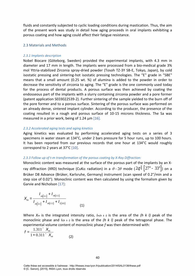
40
fluids and constantly subjected to cyclic loading conditions during mastication. Thus, the aim of the present work was study in detail how aging proceeds in oral implants exhibiting a porous coating and how aging could affect their fatigue resistance.
2.3 Materials and Methods
2.3.1 Implants description
Nobel Biocare (Göteborg, Sweden) provided the experimental implants, with 4.3 mm in diameter and 17 mm in length. The implants were processed from a bio-medical grade 3% mol Yttria-stabilized Zirconia spray-dried powder (Tosoh TZ-3Y SB-E, Tokyo, Japan), by cold isostatic pressing and sintering-hot isostatic pressing technologies. The “E‟ grade in “SBE‟ means that a small amount (0.25 wt. %) of alumina is added to the powder in order to decrease the sensitivity of zirconia to aging. The “E‟ grade is the one commonly used today for the process of dental products. A porous surface was then achieved by coating the endosseous part of the implants with a slurry containing zirconia powder and a pore former (patent application SE03022539-2). Further sintering of the sample yielded to the burn off of the pore former and to a porous surface. Sintering of the porous surface was performed on an already dense, sintered implant cylinder. According to the producer, the presence of the coating resulted in a rough and porous surface of 10-15 microns thickness. The Sa was measured in a prior work, being of 1.24 μm [16].
2.3.2 Accelerated aging tests and aging kinetics
Aging kinetics was evaluated by performing accelerated aging tests on a series of 3 specimens in water steam at 134°C, under 2 bars pressure for 5 hour runs, up to 100 hours. It has been reported from our previous records that one hour at 134°C would roughly correspond to 2 years at 37°C [10].
2.3.3 Follow up of t-m transformation of the porous coating by X-Ray Diffraction:
Monoclinic content was measured at the surface of the porous part of the implants by an X-
ray diffraction (XRD) technique (CuK radiation) in a mode ( ) on a
Brüker D8 Advance (Brüker, Karlsruhe, Germany) instrument (scan speed of 0.2°/min and a step size of 0.02°). Monoclinic content was then calculated by using the formalism given by Garvie and Nicholson [17]:
(1) Where Xm is the integrated intensity ratio, Im(h k l) is the area of the (h k l) peak of the monoclinic phase and It(h k l) is the area of the (h k l) peak of the tetragonal phase. The experimental volume content of monoclinic phase f was then determined with:
(2)
2 2q Î 27° - 33°[ ]
Xm =I
m 111( )+ I
m 111( )
Im 111( )
+ Im 111( ) + I
t 101( )
f =1.311 ´ Xm
1+ 0.311 ´ Xm
Cette thèse est accessible à l'adresse : http://theses.insa-lyon.fr/publication/2014ISAL0138/these.pdf © [C. Sanon], [2015], INSA Lyon, tous droits réservés
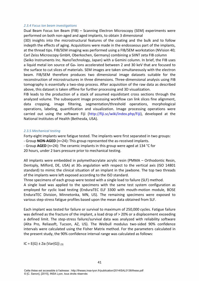
41
2.3.4 Focus Ion beam investigations
Dual Beam Focus Ion Beam (FIB) – Scanning Electron Microscopy (SEM) experiments were performed on both non-aged and aged implants, to obtain 3 dimensional (3D) insights into the microstructural features of the coating and the bulk and to follow indepth the effects of aging. Acquisitions were made in the endosseous part of the implants, at the thread tips. FIB/SEM imaging was performed using a FIB/SEM workstation (NVision 40; Carl Zeiss Microscopy GmbH, Oberkochen, Germany) combining a SIINT zeta FIB column (Seiko Instruments Inc. NanoTechnology, Japan) with a Gemini column. In brief, the FIB uses a liquid metal ion source of Ga+ ions accelerated between 2 and 30 keV that are focused to the surface to cut slices of materials. SEM images are taken simultaneously with the electron beam. FIB/SEM therefore produces two dimensional image datasets suitable for the reconstruction of microstructures in three dimensions. Three-dimensional analysis using FIB tomography is essentially a two-step process. After acquisition of the raw data as described above, this dataset is taken offline for further processing and 3D visualization. FIB leads to the production of a stack of assumed equidistant cross sections through the analyzed volume. The subsequent image processing workflow can link slices fine alignment, data cropping, image filtering, segmentation/threshold operations, morphological operations, labeling, quantification and visualization. Image processing operations were carried out using the software Fiji (http://fiji.sc/wiki/index.php/Fiji), developed at the National Institutes of Health (Bethesda, USA).
2.3.5 Mechanical testing
Forty-eight implants were fatigue tested. The implants were first separated in two groups: - Group NON-AGED (n=24): This group represented the as-received implants. - Group AGED (n=24): The ceramic implants in this group were aged at 134 °C for 20 hours, under 2 bars pressure prior to mechanical testing. All implants were embedded in polymethacrylate acrylic resin (PMMA – Orthodontic Resin, Dentsply, Milford, DE, USA) at 30o angulation with respect to the vertical axis (ISO 14801 standard) to mimic the clinical situation of an implant in the jawbone. The top two threads of the implants were left exposed according to the ISO standard. Three specimens of each group were tested with a single load to failure (SLF) method. A single load was applied to the specimens with the same test system configuration as employed for cyclic load testing (EnduraTEC ELF 3300 with mouth-motion module, BOSE EnduraTEC Division, Minnetonka, MN, US). The remaining specimens were exposed to various step-stress fatigue profiles based upon the mean data obtained from SLF. Each implant was tested for failure or survival to maximum of 250,000 cycles. Fatigue failure was defined as the fracture of the implant, a load drop of > 20% or a displacement exceeding a defined limit. The step-stress failure/survival data was analyzed with reliability software (Alta Pro, Reliasoft, Tucson, AZ, US). The Weibull modulus two-sided 90% confidence intervals were calculated using the Fisher Matrix method. For the parameters calculated in the present study, the 90% confidence interval range was calculated as follows: IC = E(G) ± Zα (Var(G)) (3)
Cette thèse est accessible à l'adresse : http://theses.insa-lyon.fr/publication/2014ISAL0138/these.pdf © [C. Sanon], [2015], INSA Lyon, tous droits réservés
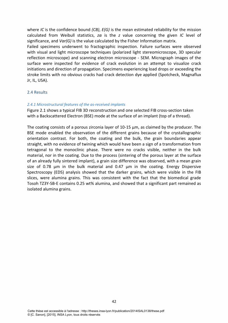
42
where IC is the confidence bound (CB), E(G) is the mean estimated reliability for the mission calculated from Weibull statistics, zα is the z value concerning the given IC level of significance, and Var(G) is the value calculated by the Fisher Information matrix. Failed specimens underwent to fractographic inspection. Failure surfaces were observed with visual and light microscope techniques (polarized light stereomicroscope, 3D specular reflection microscope) and scanning electron microscope - SEM. Micrograph images of the surface were inspected for evidence of crack evolution in an attempt to visualize crack initiations and direction of propagation. Specimens experiencing load drops or exceeding the stroke limits with no obvious cracks had crack detection dye applied (Spotcheck, Magnaflux Jr, IL, USA).
2.4 Results
2.4.1 Microstructural features of the as-received implants
Figure 2.1 shows a typical FIB 3D reconstruction and one selected FIB cross-section taken with a Backscattered Electron (BSE) mode at the surface of an implant (top of a thread). The coating consists of a porous zirconia layer of 10-15 μm, as claimed by the producer. The BSE mode enabled the observation of the different grains because of the crystallographic orientation contrast. For both, the coating and the bulk, the grain boundaries appear straight, with no evidence of twining which would have been a sign of a transformation from tetragonal to the monoclinic phase. There were no cracks visible, neither in the bulk material, nor in the coating. Due to the process (sintering of the porous layer at the surface of an already fully sintered implant), a grain size difference was observed, with a mean grain size of 0.78 μm in the bulk material and 0.47 μm in the coating. Energy Dispersive Spectroscopy (EDS) analysis showed that the darker grains, which were visible in the FIB slices, were alumina grains. This was consistent with the fact that the biomedical grade Tosoh TZ3Y-SB-E contains 0.25 wt% alumina, and showed that a significant part remained as isolated alumina grains.
Cette thèse est accessible à l'adresse : http://theses.insa-lyon.fr/publication/2014ISAL0138/these.pdf © [C. Sanon], [2015], INSA Lyon, tous droits réservés
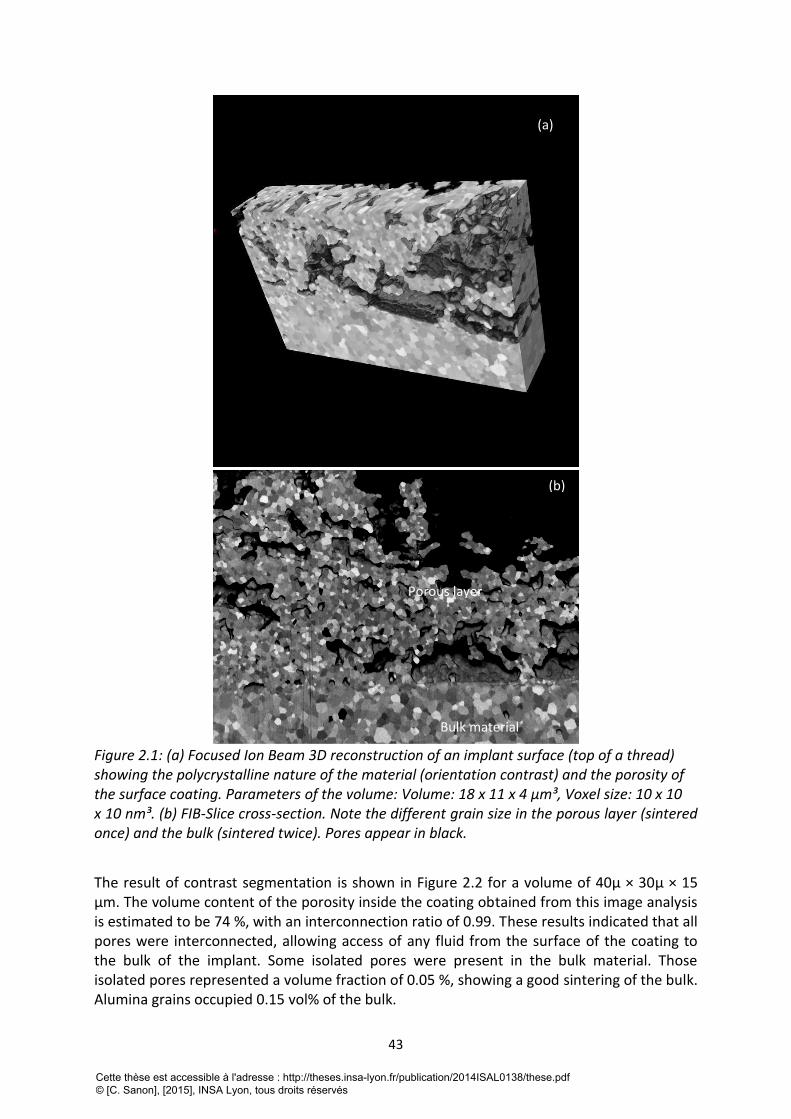
43
Figure 2.1: (a) Focused Ion Beam 3D reconstruction of an implant surface (top of a thread) showing the polycrystalline nature of the material (orientation contrast) and the porosity of the surface coating. Parameters of the volume: Volume: 18 x 11 x 4 μm³, Voxel size: 10 x 10 x 10 nm³. (b) FIB-Slice cross-section. Note the different grain size in the porous layer (sintered once) and the bulk (sintered twice). Pores appear in black.
The result of contrast segmentation is shown in Figure 2.2 for a volume of 40µ × 30µ × 15 μm. The volume content of the porosity inside the coating obtained from this image analysis is estimated to be 74 %, with an interconnection ratio of 0.99. These results indicated that all pores were interconnected, allowing access of any fluid from the surface of the coating to the bulk of the implant. Some isolated pores were present in the bulk material. Those isolated pores represented a volume fraction of 0.05 %, showing a good sintering of the bulk. Alumina grains occupied 0.15 vol% of the bulk.
(a)
(b)
Porous layer
Bulk material
Cette thèse est accessible à l'adresse : http://theses.insa-lyon.fr/publication/2014ISAL0138/these.pdf © [C. Sanon], [2015], INSA Lyon, tous droits réservés
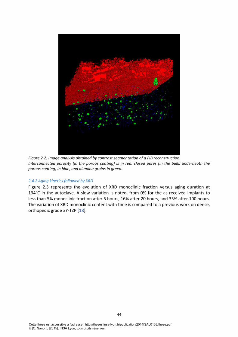
44
Figure 2.2: Image analysis obtained by contrast segmentation of a FIB reconstruction. Interconnected porosity (in the porous coating) is in red, closed pores (in the bulk, underneath the porous coating) in blue, and alumina grains in green.
2.4.2 Aging kinetics followed by XRD
Figure 2.3 represents the evolution of XRD monoclinic fraction versus aging duration at 134°C in the autoclave. A slow variation is noted, from 0% for the as-received implants to less than 5% monoclinic fraction after 5 hours, 16% after 20 hours, and 35% after 100 hours. The variation of XRD monoclinic content with time is compared to a previous work on dense, orthopedic grade 3Y-TZP [18].
Cette thèse est accessible à l'adresse : http://theses.insa-lyon.fr/publication/2014ISAL0138/these.pdf © [C. Sanon], [2015], INSA Lyon, tous droits réservés
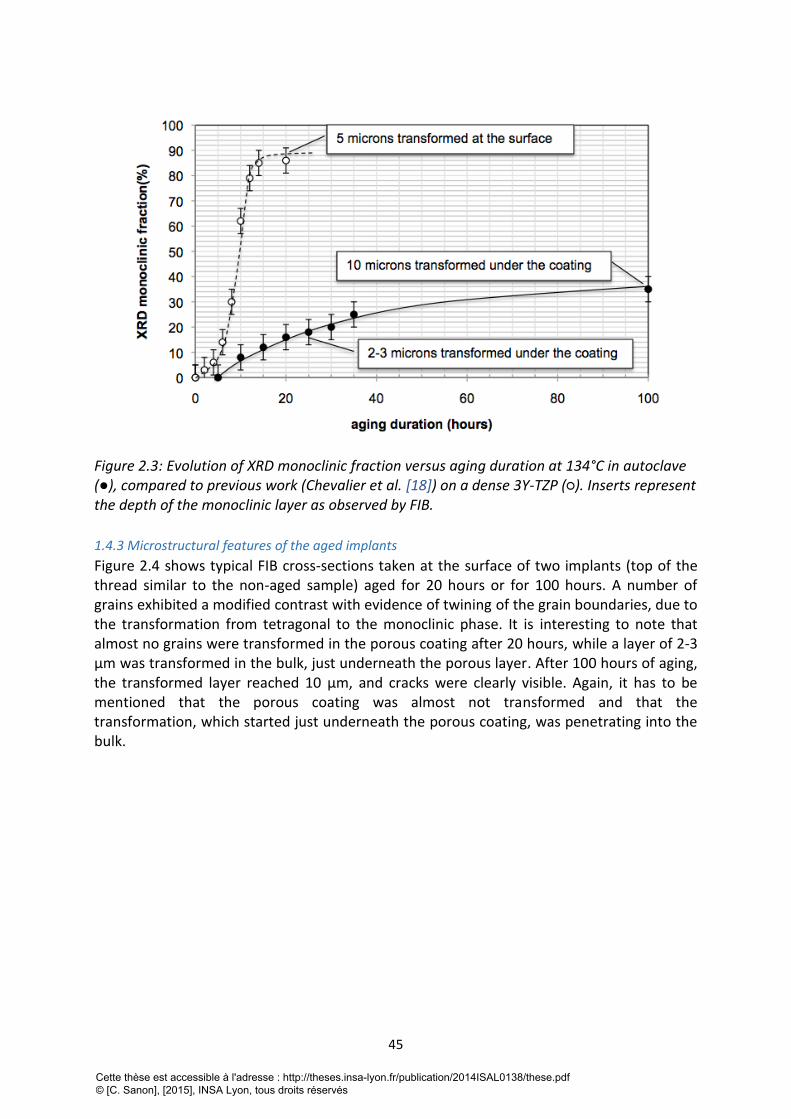
45
Figure 2.3: Evolution of XRD monoclinic fraction versus aging duration at 134°C in autoclave (●), compared to previous work (Chevalier et al. [18]) on a dense 3Y-TZP (○). Inserts represent the depth of the monoclinic layer as observed by FIB.
1.4.3 Microstructural features of the aged implants
Figure 2.4 shows typical FIB cross-sections taken at the surface of two implants (top of the thread similar to the non-aged sample) aged for 20 hours or for 100 hours. A number of grains exhibited a modified contrast with evidence of twining of the grain boundaries, due to the transformation from tetragonal to the monoclinic phase. It is interesting to note that almost no grains were transformed in the porous coating after 20 hours, while a layer of 2-3 μm was transformed in the bulk, just underneath the porous layer. After 100 hours of aging, the transformed layer reached 10 μm, and cracks were clearly visible. Again, it has to be mentioned that the porous coating was almost not transformed and that the transformation, which started just underneath the porous coating, was penetrating into the bulk.
Cette thèse est accessible à l'adresse : http://theses.insa-lyon.fr/publication/2014ISAL0138/these.pdf © [C. Sanon], [2015], INSA Lyon, tous droits réservés
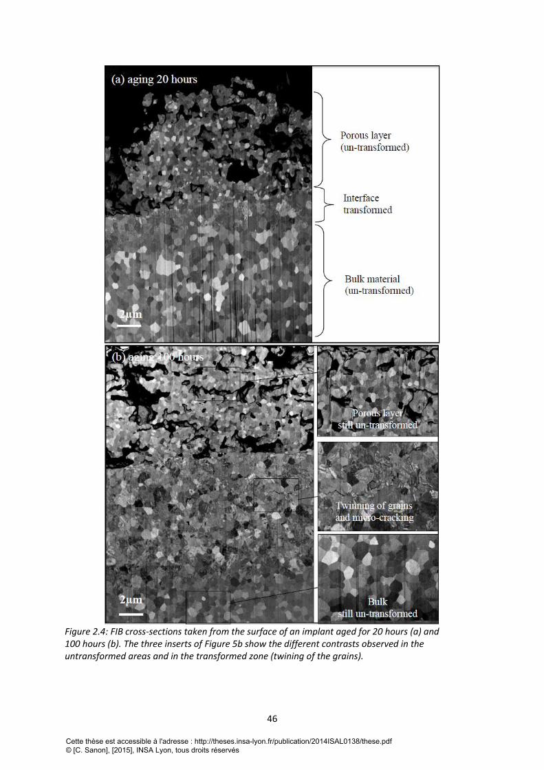
46
Figure 2.4: FIB cross-sections taken from the surface of an implant aged for 20 hours (a) and 100 hours (b). The three inserts of Figure 5b show the different contrasts observed in the untransformed areas and in the transformed zone (twining of the grains).
Cette thèse est accessible à l'adresse : http://theses.insa-lyon.fr/publication/2014ISAL0138/these.pdf © [C. Sanon], [2015], INSA Lyon, tous droits réservés
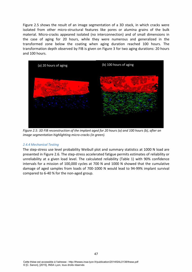
47
Figure 2.5 shows the result of an image segmentation of a 3D stack, in which cracks were isolated from other micro-structural features like pores or alumina grains of the bulk material. Micro-cracks appeared isolated (no interconnection) and of small dimensions in the case of aging for 20 hours, while they were numerous and generalized in the transformed zone below the coating when aging duration reached 100 hours. The transformation depth observed by FIB is given on Figure 3 for two aging durations: 20 hours and 100 hours.
Figure 2.5: 3D FIB reconstruction of the implant aged for 20 hours (a) and 100 hours (b), after an image segmentation highlighting micro-cracks (in green).
2.4.4 Mechanical Testing
The step-stress use level probability Weibull plot and summary statistics at 1000 N load are presented in Figure 2.6. The step-stress accelerated fatigue permits estimates of reliability or unreliability at a given load level. The calculated reliability (Table 1) with 90% confidence intervals for a mission of 100,000 cycles at 700 N and 1000 N showed that the cumulative damage of aged samples from loads of 700-1000 N would lead to 94-99% implant survival compared to 6-40 % for the non-aged group.
(a) 20 hours of aging (b) 100 hours of aging
Cette thèse est accessible à l'adresse : http://theses.insa-lyon.fr/publication/2014ISAL0138/these.pdf © [C. Sanon], [2015], INSA Lyon, tous droits réservés
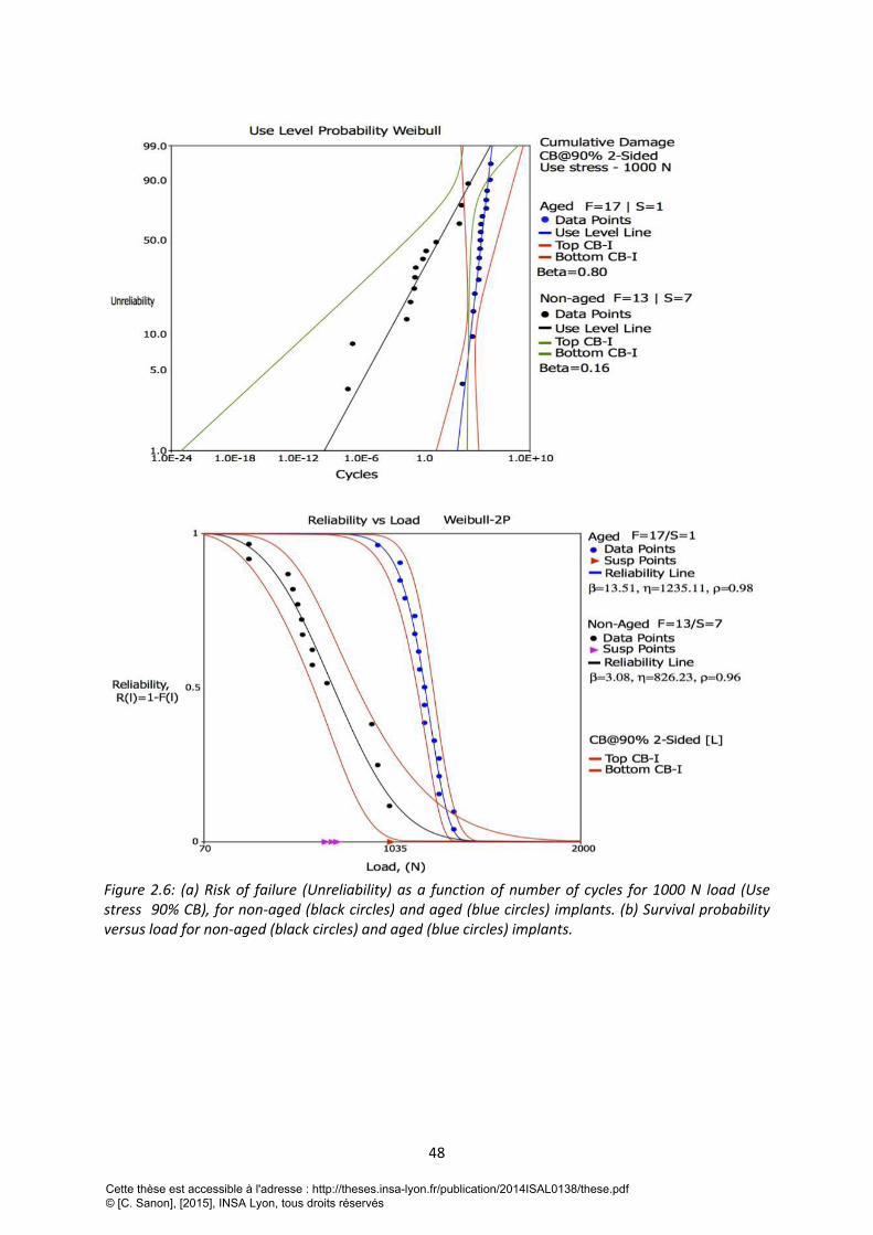
48
Figure 2.6: (a) Risk of failure (Unreliability) as a function of number of cycles for 1000 N load (Use stress 90% CB), for non-aged (black circles) and aged (blue circles) implants. (b) Survival probability versus load for non-aged (black circles) and aged (blue circles) implants.
Cette thèse est accessible à l'adresse : http://theses.insa-lyon.fr/publication/2014ISAL0138/these.pdf © [C. Sanon], [2015], INSA Lyon, tous droits réservés
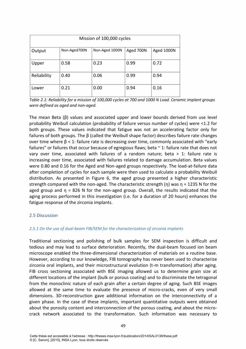
49
Mission of 100,000 cycles
Output
Non-Aged700N Non-Aged 1000N Aged 700N Aged 1000N
Upper
0.58 0.23 0.99 0.72
Reliability
0.40 0.06 0.99 0.94
Lower 0.21 0.00 0.94 0.16
Table 2.1: Reliability for a mission of 100,000 cycles at 700 and 1000 N Load. Ceramic implant groups were defined as aged and non-aged.
The mean Beta (β) values and associated upper and lower bounds derived from use level probability Weibull calculation (probability of failure versus number of cycles) were <1.2 for both groups. These values indicated that fatigue was not an accelerating factor only for failures of both groups. The β (called the Weibull shape factor) describes failure rate changes over time where β < 1: failure rate is decreasing over time, commonly associated with “early failures” or failures that occur because of egregious flaws; beta ~ 1: failure rate that does not vary over time, associated with failures of a random nature; beta > 1: failure rate is increasing over time, associated with failures related to damage accumulation. Beta values were 0.80 and 0.16 for the Aged and Non-aged groups respectively. The load-at-failure data after completion of cycles for each sample were then used to calculate a probability Weibull distribution. As presented in Figure 6, the aged group presented a higher characteristic strength compared with the non-aged. The characteristic strength (η) was η = 1235 N for the aged group and η = 826 N for the non-aged group. Overall, the results indicated that the aging process performed in this investigation (i.e. for a duration of 20 hours) enhances the fatigue response of the zirconia implants.
2.5 Discussion
2.5.1 On the use of dual-beam FIB/SEM for the characterization of zirconia implants
Traditional sectioning and polishing of bulk samples for SEM inspection is difficult and tedious and may lead to surface deterioration. Recently, the dual-beam focused ion beam microscope enabled the three-dimensional characterization of materials on a routine base. However, according to our knowledge, FIB tomography has never been used to characterize zirconia oral implants, and their microstructural evolution (t-m transformation) after aging. FIB cross sectioning associated with BSE imaging allowed us to determine grain size at different locations of the implant (bulk or porous coating) and to discriminate the tetragonal from the monoclinic nature of each grain after a certain degree of aging. Such BSE images allowed at the same time to evaluate the presence of micro-cracks, even of very small dimensions. 3D-reconstruction gave additional information on the interconnectivity of a given phase. In the case of these implants, important quantitative outputs were obtained about the porosity content and interconnection of the porous coating, and about the micro-crack network associated to the transformation. Such information was necessary to
Cette thèse est accessible à l'adresse : http://theses.insa-lyon.fr/publication/2014ISAL0138/these.pdf © [C. Sanon], [2015], INSA Lyon, tous droits réservés
50
understand the behavior of these specific implants versus aging. The evolution of XRD monoclinic content versus time was apparently low, and much lower than previously published kinetics on the same material [18]. Without any further analysis, one could have argued that the present implants exhibited a slow transformation after 20 or even after 100 hours. However, the volume fraction obtained by XRD is an average integrated volume fraction on the penetration depth of the X-Rays. In dense zirconia, the penetration depth of the X-Rays is of 5 μm (calculations with AbsorbDX software, DIFFRACplus BASIC Evaluation Package, Bruker, Karlsruhe, Germany). For a zirconia ceramic with 26 % density – as it is with the porous coating the penetration depth of the X-Rays is calculated to be 15 μm. FIB experiments showed that the tetragonal to monoclinic transformation occurred generally not in the coating area but underneath, below the interface coating – bulk material. Since the XRD penetrates only between 5 – 15 μm into the material and the coating itself has a thickness of 10 – 15 μm, XRD was unable to characterize properly the transformation rate features throughout the bulk of the implant below the coating. In other words, XRD data only would lead to a strong underestimation of the transformation in the bulk material. Alone, as it is often conducted in most of studies, XRD is not able to capture all the features of the t-m transformation occurring at or near the surface of zirconia implants. Therefore, as FIB/SEM is becoming an accessible tool in materials science, we urge the community to utilize such technique in the panoply of techniques to investigate t-m transformation in zirconia. The transformation started at the interface between the porous coating and the bulk, and propagated into the bulk. Such observations are easily explained by the larger grain size of the zirconia grains in the bulk, and by the fact that large grains at the interface are in contact with water thanks to the interconnected porosity of the coating.
2.5.2 On the mechanical performances of aged zirconia implants
There was evidence that the zirconia implants of the present study possessed higher fatigue resistance and strength after 20 hours aging. This is in apparent contrast with the common thinking that the t-m transformation associated to aging decreases the strength of zirconia by producing a micro-crack zone. However, some previous reports showed that substantial degree of transformation did not lead necessarily to a decrease in strength [19] or even led to a substantial increase in strength and/or reliability [20,21]. The outstanding review performed by Piconi and Maccauro more than 10 years ago on orthopedic implants shows that the strength of zirconia can decrease or increase with aging time [22]. Indeed, strength variation with LTD depends on the balance between accumulation of residual compressive stresses and micro cracking in the monoclinic layer. Compressive stresses of monoclinic grains are generated by their 4% volume expansion during t-m transformation. On the other side, micro cracks are generated by tensile stresses at the interface with tetragonal grains, which would act to decrease strength. Therefore aging cannot be systematically associated with a loss in strength. In the case of the present implants, FIB/SEM investigation showed that, after 20 hours of aging in the autoclave, micro cracks were limited in number and size, not connected and parallel to the surface. The number of cracks was increasing with aging duration, reaching a high density for an aging treatment of 100 hours in the autoclave. Small isolated cracks (as it was the case for 20 hours of aging), which were not subjected to tensile
Cette thèse est accessible à l'adresse : http://theses.insa-lyon.fr/publication/2014ISAL0138/these.pdf © [C. Sanon], [2015], INSA Lyon, tous droits réservés
51
stresses in bending, did not act as critical defects being able to decrease the strength. Fatigue tests were not performed for implants after 100 hours of aging, since it would have been certainly un-relevant as far as the lifetime of real components is concerned, but it would have probably led to a strong drop of strength because the density and the size of cracks would have reached a critical degree. Having an increase in strength and fatigue resistance is also not sufficient to claim that aging has no negative influence on the structural integrity of such zirconia implants. Indeed, such micro cracks, might continue by slow crack growth during mastication and lead to delamination and loss of the porous coating. Investigations on in-vivo oral implant explants are currently conducted to assess this potential delamination issue. With this latter aspect in mind, we strongly believe that aging should be avoided, even if it seemed to increase strength or fatigue resistance as presented in the present investigation.
2.6 Conclusions
- Combined FIB/SEM was powerful for the investigation of t-m transformation in zirconia oral implants. It provided 3D-quantitative characterizations that could not be obtained with other techniques such as XRD. In the case of the present implants, only FIB allowed to describe the transformation features and their consequences on mechanical performances. - In contrast with common thinking and previous results performed on bend bars, aging was not associated with a loss of bending strength or fatigue resistance. Strength obviously resulted from a balance between compressive stresses and micro cracking occurring in the transformed areas. Aging, however, showed a loss in structural integrity of which we do not yet comprehend the possible clinical consequences. - Our results confirm that generalizations must be avoided when considering aging of zirconia dental products and that every new material/process combination should be tested before drawing conclusions.
2.7 Acknowledgments:
Thanks are due to the CLYM (Centre Lyonnais de Microscopie: www.clym.fr) for the access to the microscope FIB ZEISS, NVISION 40. CLYM is supported by the CNRS, the “Grand Lyon” and the “Rhône-Alpes Region”. The authors thank Nobel Biocare for providing the implant prototypes for this study. Dr. Leandro M. Martins from Federal University of Manus, Brazil is acknowledged for his contribution during the fatigue testing. The fatigue test and data calculation were performed in the Department of Biomaterials and Biomimetics at New York University College of Dentistry, USA.
2.8 Réferences bibliographiques de la deuxième partie
[1] Christel P, Meunier A, Dorlot JM, Crolet JM, Witvoet J, Sedel L, Boutin P. Biomechanical compatibility and design of ceramic implants for orthopedic surgery. Ann NY Acad Sci, 1988;523:234-256. [2] Chevalier J. What future for zirconia as a biomaterial? Biomater, 2006;27:535-543.
Cette thèse est accessible à l'adresse : http://theses.insa-lyon.fr/publication/2014ISAL0138/these.pdf © [C. Sanon], [2015], INSA Lyon, tous droits réservés
52
[3] Koutayas SO, Vagkopoulou T, Pelekanos S, Koidis P, Strub JR. Zirconia in Dentistry: Part 2. Evidence-based clinical breakthrough. Eur J Esthet Dent, 2009;4: 348-380. [4] Rimondini L, Cerroni L, Carrassi A, Torricelli P. Bacterial colonization of zirconia ceramic surfaces: an in vitro and in vivo study. Int J Oral Maxillofac Implants, 2002;17:793-8. [5] Scarano A, Piattelli M, Caputi S, Favero GA, Piattelli A. Bacterial adhesion on commercially pure titanium and zirconium oxide disks: an in vivo human study. J Periodontol,2004;75:292-6. [6] Blaschke C, Volz U (2006). Soft and hard tissue response to zirconium dioxide dental implants-a clinical study in man. Neuro Endocrinol Lett,2006 ;27 Suppl 1: 69-72. [7] Kohal RJ, Weng D, Bächle M, Strub JR. Loaded custom-made zirconia and titanium implants show similar osseointegration: an animal experiment. J Periodontol,2004;75:1262- 1268. [8] Dunn DB. The use of a zirconia custom implant-supported fixed partial denture prosthesis to treat implant failure in the anterior maxilla: A clinical report. J Prosthet Dent,2008;100:415-21. [9] Chevalier J, Gremillard L, Virkar A, Clarke DR. The tetragonal-monoclinic transformation in zirconia: Lessons learned and future trends. J Am Ceram Soc,2009;92:1901-1920. [10] Chevalier J, Gremillard L, Deville S. Low-temperature degradation of zirconia and implications for biomedical implants. Ann Rev Mater Res,2007;37:1-32. [11] Manicone P, Rossi Iommetti P, Raffaelli L (2007). An overview of zirconia ceramics: Basic properties and clinical applications. J Dent,2007;35:819-826. [12] Studart A, Filser F, Kocher P, Gauckler L. Fatigue of zirconia under cyclic loading in water and its implications for the design of dental bridges. Dent Mat, 2007;23:106–14. [13] Yamashita D, Machigashira M, Miyamoto M, Takeuchi H, Noguchi K, Izumi Y, Ban S. Effect of surface roughness on initial responses of osteoblast-like cells on two types of zirconia. Dent Mater J,2009;28:461-470. [14] Depprich R, Zipprich H, Ommerborn M, Naujoks C, Wiesmann HP, Kiattavorncharoen S, Lauer HC, Meyer U, Kübler NR, Handschel J. Osseointegration of zirconia implants compared with titanium: An in vivo study. Head Face Med,2008;4: art.30. [15] Sennerby L, Dasmah A, Larsson B, Iverhed M (2005). Bone tissue responses to surfacemodified zirconia implants: A histomorphometric and removal torque study in the rabbit. Clin Implant Dent Relat Res, 2005;7:13-20. [16] Kohal RJ, Knauf M, Larsson B, Sahlin H, Butz F. One-piece zirconia oral implants: Oneyear results from a prospective cohort study. 1. Single tooth replacement. J Clin Periodontol, 2012;39:590-597. [17] Garvie RC, Nicholson PS. Phase analysis in zirconia systems. J Am Ceram Soc, 1972;55:303-305. [18] Chevalier J, Cales B, Drouin JM. Low-temperature aging of Y-TZP ceramics. J Am Ceram Soc,1999;82:2150-2154. [19] Borchers L, Stiesch M, Bac FW, Buhl JC, Hübsch C, Kellner T, Kohorst P, Jendras M. Influence of hydrothermal and mechanical conditions on the strength of zirconia. Acta Biomater, 2010;6:4547-4552. [20] Chevalier J, Loh J, Gremillard L, Meille S, Adolfson E. Low Temperature Degradation in zirconia with a porous surface. Acta Biomater,2011;7: 2986-2993. [21] Marro FG, Anglada M. Strengthening of Vickers indented 3Y-TZP by hydrothermal ageing. J Eur Ceram Soc,2012;32: 317–324. [22] Piconi C, Maccauro G. Zirconia as a ceramic biomaterial. Biomater,1999;20:1-25.
Cette thèse est accessible à l'adresse : http://theses.insa-lyon.fr/publication/2014ISAL0138/these.pdf © [C. Sanon], [2015], INSA Lyon, tous droits réservés
53
TROISIEME PARTIE: DEVELOPPEMENT D’UN PROTOCOLE D’EVALUATION POUR
LES IMPLANTS DENTAIRES EN ZIRCONE
1. Introduction Après avoir établi la relation existant entre la microstructure et le comportement de l’implant Ziunite
au cours du temps, et avoir détecté certaines limites des techniques d’évaluation et des
recommandations actuelles, nous souhaitions développer un protocole d’évaluation reproductible,
qui permettrait de caractériser les implants et de suivre simultanément l’évolution de la résistance
mécanique et la microstructure au cours du temps. Ce protocole est présenté, également sous forme
d’une publication internationale, actuellement en édition dans la revue Dental materials. Cette
publication est complétée par une discussion sur l’apport de la microscopie à faisceaux d’ions
focalisés (FIB) à l’analyse et la quantification de la transformation de phase de la zircone.
2. “A new testing protocol for zirconia dental implants”
2.1 Abstract
Objectives: Based on the current lack of standards concerning zirconia dental implants, we aim at developing a protocol to validate their functionality and safety prior their clinical use. The protocol is designed to account for the specific brittle nature of ceramics and the specific behavior of zirconia in terms of phase transformation.
Methods: Several types of zirconia dental implants with different surface textures (porous, alveolar, rough) were assessed. The implants were first characterized in their as-received state by Scanning Electron Microscopy (SEM), Focused Ion Beam (FIB), X-Ray Diffraction (XRD). Fracture tests following a method adapted from ISO 14801 were conducted to evaluate their initial mechanical properties. Accelerated aging was performed on the implants, and XRD monoclinic content measured directly at their surface instead of using polished samples as in ISO 13356. The implants were then characterized again after aging.
Results: Implants with an alveolar surface presented large defects. The protocol shows that such defects compromise the long-term mechanical properties. Implants with a porous surface exhibited sufficient strength but a significant sensitivity to aging. Even if associated to micro cracking clearly observed by FIB, aging did not decrease mechanical strength of the implants.
Significance: As each dental implant company has its own process, all zirconia implants may behave differently, even if the starting powder is the same. Especially, surface modifications have a large influence on strength and aging resistance, which is not taken into account by the current standards. Protocols adapted from this work could be useful.
Keywords: zirconia, implants, phase transformation, fracture, surface, aging.
2.2 Introduction:
Oral implants offer an effective treatment for replacement of missing teeth. Since the
pioneering works of Brånemark in the 60’s 1, several millions of titanium implants have been produced. It is reported that the oral implant number will grow at a rate of 6% per year
Cette thèse est accessible à l'adresse : http://theses.insa-lyon.fr/publication/2014ISAL0138/these.pdf © [C. Sanon], [2015], INSA Lyon, tous droits réservés
54
from 2010 to 2015, since there is a tendency to propose more and more implants to patients
to improve their quality of life (aesthetic, but also mastication and long-term stability) 2. Current long-term clinical investigations (more than 10 years of follow-up) report very favorable survival rates, which places titanium and its biomedical alloys as the gold standard
3. However, in some cases, the greyish color of a titanium implant may be perceived
through the peri-implant mucosa causing some aesthetic drawbacks 4. Furthermore, in
rare cases, metals (including titanium) may induce sensitization or allergic reactions 5,6. Finally, some patients also ask for completely metal-free dental reconstructions. Thus, implants fabricated with ceramic materials are gaining popularity and might have a certain clinical and industrial success if they prove to be strong enough, stable over time and well integrated in the jawbone. Especially, yttria-doped zirconia ceramics (often referred as 3Y-TZP, standing for 3 mol.% Yttria doped Zirconia Tetragonal Polycristals) are often presented
as the alternative to titanium 7. These ceramics possess good mechanical strength 8,
excellent tissue compatibility and show osseointegration comparable to that of titanium 9.
A further advantage of zirconia is the reduced formation of plaque 10. Moreover, the white-opaque ZrO2 ceramic better resembles the tooth in terms of color, and thus provides good esthetics even with a thin gingiva or with soft-tissue recessions.
Worldwide, there are more than 10 companies producing zirconia dental implants and each manufacturer develops its process, its implant design and its own surface features to promote osseointegration. It is generally accepted that rough surfaces improve osseointegration and favor mechanical anchorage with bone. Several strategies are explored to process rough or porous surface implant i.e. machining, acid etching, sandblasting,
molding or coating with a porous layer 11-13. Although zirconia has good initial mechanical properties (high fracture toughness and bending strength), it remains a ceramic material with a significant sensitivity to surface defects. The above-mentioned surface treatments may generate cracks and/or defects which could be detrimental for mechanical properties of these zirconia implants. Moreover, screw design allows mechanical anchorage of dental implant into the bone but is challenging for ceramics material because of stress
concentration at sharp edges 14. All these aspects are poorly documented in the recent literature on zirconia dental implants. It has also to be recalled at this stage that 3Y-TZP was introduced as an implant biomaterial (femoral heads) in orthopedics over 30 years ago, but was abandoned after 15 years of use, after a series of failures in specific batches
manufactured with a new process 15. Zirconia is a complex material because it is meta-stable at room temperature. On the one hand, its excellent mechanical properties (the best of oxide ceramics) are due to the transformation of metastable tetragonal grains to the monoclinic phase under stress (for example in the vicinity of a crack). The development of this transformation zone is accompanied by an increase of crack resistance, which is known
as phase transformation toughening 16. On the other hand, this meta-stability leads to a possible transformation of grains in contact with water (or body fluids) with time. This phenomenon is often referred as to Low Temperature Degradation (LTD) or aging. Aging is a progressive tetragonal to monoclinic transformation at the surface triggered by the presence
of water 16, which often results in surface roughening and micro cracking and thereby potentially decreases the device physicochemical and mechanical properties. The experience of zirconia in orthopedics field gave some important indications on how aging may proceed, on the potential impact of the transformation and on the conditions by which it may be triggered. The transformation proceeds from the surface in contact with water to the bulk of
Cette thèse est accessible à l'adresse : http://theses.insa-lyon.fr/publication/2014ISAL0138/these.pdf © [C. Sanon], [2015], INSA Lyon, tous droits réservés
55
the material. The kinetics by which the transformation occurs is highly dependent on process
conditions and resulting microstructure 17. Surface modifications for example may have a positive effect on bone apposition and bone in-growth, but also could facilitate the water penetration into the bulk and/or lead to a modification of the stability of the tetragonal phase under humid atmosphere. Except few
recent works, including one from the authors of the current paper 18, the risk of lifetime reduction associated to surface modification of implants is barely discussed. There is today no standardized protocol that allows assessing the mechanical properties of the implant, to determine the aging kinetics and the effects of aging on the mechanical properties for a
given type of implant. The only ISO standard 19 concerning medical grade zirconia is based on mechanical strength and aging kinetics measured on bending bars or discs, which are polished and therefore not relevant for dental implants. To bridge this gap, we aim at proposing a protocol to validate the functionality and safety of zirconia implants prior their clinical use. The protocol is designed to account for the specific brittle nature of ceramics (sensitive to surface defects and slow crack growth) and the specific behavior of zirconia in terms of phase transformation.
2.3 Materials and method
2.3.1 Implant description
For this research, Axis Biodental provided two types of 3Y-TZP dental implants processed by injection molding, with either a structured rough surface, which will be referred as ‘Axis-rough’ or with an additional proprietary porous zirconia coating here referred as ‘Axis-alveolar’ in relation with their surface texture. Axis-rough surface was obtained after surface treatment of the mold inner and the alveolar one, after deposition and sintering of a mixture of zirconia powder and polymer beads (patent application EP 1924300 B1). Only the ‘Axis-rough’ implants were commercial implants, while ‘Axis-alveolar’ were prototypes in the development phase.
Nobel Biocare provided zirconia implant prototypes with a porous surface (ZiUnite®). The porous surface was achieved after sintering, by coating the endosseous part of the implants with a slurry containing zirconia powder and a pore former (patent application SE03022539-2). Further sintering of the implants yielded to the burn off of the pore former and to a porous surface. The presence of the coating gave rise to a rough and porous, 15 μm-thick surface layer according to the manufacturer.
It is to note that all implants were processed from a biomedical grade 3% mol. yttria-stabilized zirconia powder (Tosoh TZ-3Y-E, Tokyo, Japan).
2.3.2 Microstructural characterization
Microstructural aspect of the two types of implants was investigated using a Scanning Electron Microscope (Supra 40, Carl Zeiss AG, Oberkochen, Germany) to analyze the surface and a dual beam Focus Ion Beam (FIB) for further investigation in-depth. FIB acquisitions were made on the endosseous part of the implants. FIB/SEM imaging was performed using a FIB/SEM workstation (NVision 40; Carl Zeiss Microscopy GmbH, Oberkochen, Germany) combining a SIINT zeta FIB column (Seiko Instruments Inc. NanoTechnology, Japan) with a
Cette thèse est accessible à l'adresse : http://theses.insa-lyon.fr/publication/2014ISAL0138/these.pdf © [C. Sanon], [2015], INSA Lyon, tous droits réservés
56
Gemini column. In brief, the FIB uses a liquid metal ion source of Ga+ ions accelerated between 2 and 30 keV that are focused to the surface to cut slices of materials. SEM images are taken simultaneously with the electron beam. FIB/SEM therefore produces two dimensional image datasets that can be used as cross-sections, but that are also suitable for the reconstruction of microstructures in three dimensions. Three-dimensional analysis using FIB tomography is essentially a two-step process. After acquisition of the raw data as described above, this dataset is taken offline for further processing and 3D visualization. FIB leads to the production of a stack of assumed equidistant cross sections (distance between two cross-sections: 10 nm) through the analyzed volume. The subsequent image processing workflow can link slices fine alignment, data cropping, image filtering, segmentation/threshold operations, morphological operations, labeling, quantification and visualization. Image processing operations were carried out using the software Fiji (http://fiji.sc/wiki/index.php/Fiji), developed at the National Institutes of Health (Bethesda, USA).
2.3.3 Aging kinetics
Aging tests were performed in water steam at 134°C, under 2 bars pressure for durations up to 100 hours. It has been reported from our previous records that one hour at 134°C would roughly correspond to 2 years at 37°C. This is a rough estimation that can be debated but which gives an idea of treatment durations relevant for the application. Monoclinic content was measured at the surface the endosseous part of the implants by an X-ray diffraction
(XRD) technique (CuK radiation) in a mode ( ) on a Brüker D8
Advance (Brüker, Karlsruhe, Germany) instrument (scan speed of 0.2°/min and a step size of 0.02°). Monoclinic content was then calculated by using the formalism given by Garvie and Nicholson:
(1)
Where Xm is the integrated intensity ratio, Im(h k l) is the area of the (h k l) peak of the monoclinic phase and It(h k l) is the area of the (h k l) peak of the tetragonal phase. The experimental volume content of monoclinic phase f was then determined with:
(2)
The procedure was generally conducted directly at the surface of the implants, on the threaded (endosseous) area. However, in order to assess the influence of surface preparation on aging kinetics, the kinetics was also measured on sectioned and mirror-polished implants, as it is still recommended by the ISO 13356 standard.
Effects of aging were specially examined after 5 hours of artificial aging at 134°C, because this aging duration represents the range of the lifetime expected for endosseous implants. 5 hours corresponds to 10-20 years in vivo.
2.3.4 Mechanical characterization
Only Axis implants were characterized in terms of load to failure. Indeed, the objective was not to compare the mechanical strength of different types of implants (they do not present
2 2q Î 27° - 33°[ ]
Xm =I
m 111( )+ I
m 111( )
Im 111( )
+ Im 111( ) + I
t 101( )
f =1.311 ´ Xm
1+ 0.311 ´ Xm
Cette thèse est accessible à l'adresse : http://theses.insa-lyon.fr/publication/2014ISAL0138/these.pdf © [C. Sanon], [2015], INSA Lyon, tous droits réservés
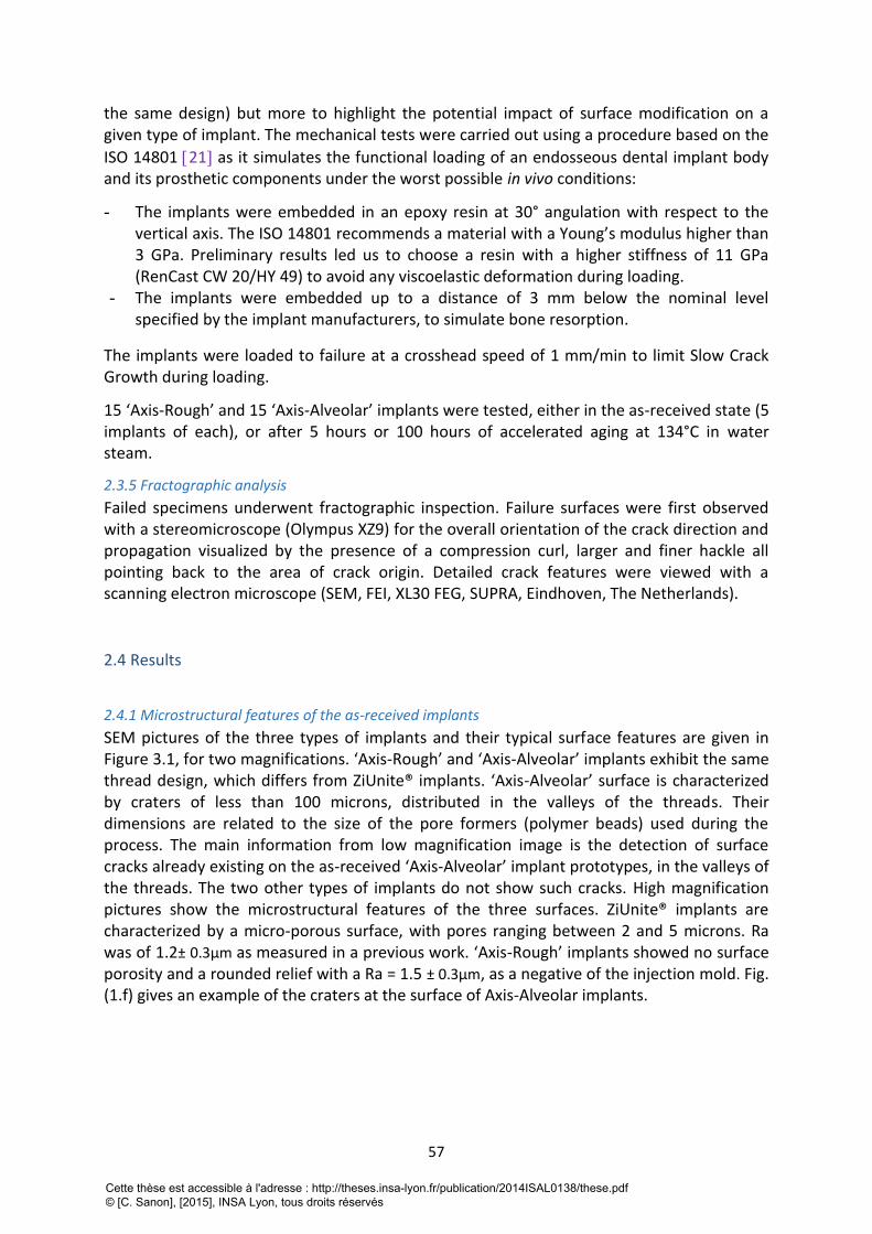
57
the same design) but more to highlight the potential impact of surface modification on a given type of implant. The mechanical tests were carried out using a procedure based on the
ISO 14801 21 as it simulates the functional loading of an endosseous dental implant body and its prosthetic components under the worst possible in vivo conditions:
- The implants were embedded in an epoxy resin at 30° angulation with respect to the vertical axis. The ISO 14801 recommends a material with a Young’s modulus higher than 3 GPa. Preliminary results led us to choose a resin with a higher stiffness of 11 GPa (RenCast CW 20/HY 49) to avoid any viscoelastic deformation during loading.
- The implants were embedded up to a distance of 3 mm below the nominal level specified by the implant manufacturers, to simulate bone resorption.
The implants were loaded to failure at a crosshead speed of 1 mm/min to limit Slow Crack Growth during loading.
15 ‘Axis-Rough’ and 15 ‘Axis-Alveolar’ implants were tested, either in the as-received state (5 implants of each), or after 5 hours or 100 hours of accelerated aging at 134°C in water steam.
2.3.5 Fractographic analysis
Failed specimens underwent fractographic inspection. Failure surfaces were first observed with a stereomicroscope (Olympus XZ9) for the overall orientation of the crack direction and propagation visualized by the presence of a compression curl, larger and finer hackle all pointing back to the area of crack origin. Detailed crack features were viewed with a scanning electron microscope (SEM, FEI, XL30 FEG, SUPRA, Eindhoven, The Netherlands).
2.4 Results
2.4.1 Microstructural features of the as-received implants
SEM pictures of the three types of implants and their typical surface features are given in Figure 3.1, for two magnifications. ‘Axis-Rough’ and ‘Axis-Alveolar’ implants exhibit the same thread design, which differs from ZiUnite® implants. ‘Axis-Alveolar’ surface is characterized by craters of less than 100 microns, distributed in the valleys of the threads. Their dimensions are related to the size of the pore formers (polymer beads) used during the process. The main information from low magnification image is the detection of surface cracks already existing on the as-received ‘Axis-Alveolar’ implant prototypes, in the valleys of the threads. The two other types of implants do not show such cracks. High magnification pictures show the microstructural features of the three surfaces. ZiUnite® implants are characterized by a micro-porous surface, with pores ranging between 2 and 5 microns. Ra was of 1.2± 0.3μm as measured in a previous work. ‘Axis-Rough’ implants showed no surface porosity and a rounded relief with a Ra = 1.5 ± 0.3μm, as a negative of the injection mold. Fig. (1.f) gives an example of the craters at the surface of Axis-Alveolar implants.
Cette thèse est accessible à l'adresse : http://theses.insa-lyon.fr/publication/2014ISAL0138/these.pdf © [C. Sanon], [2015], INSA Lyon, tous droits réservés
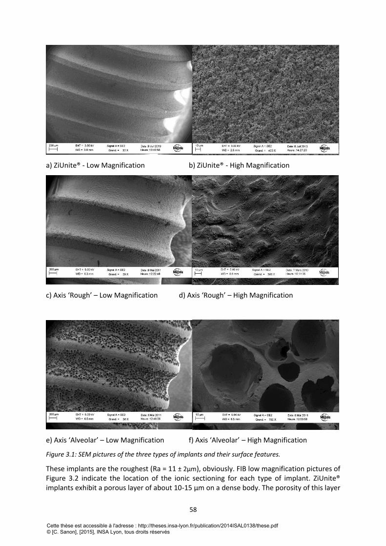
58
a) ZiUnite® - Low Magnification b) ZiUnite® - High Magnification
c) Axis ‘Rough’ – Low Magnification d) Axis ‘Rough’ – High Magnification
e) Axis ‘Alveolar’ – Low Magnification f) Axis ‘Alveolar’ – High Magnification
Figure 3.1: SEM pictures of the three types of implants and their surface features.
These implants are the roughest (Ra = 11 ± 2μm), obviously. FIB low magnification pictures of Figure 3.2 indicate the location of the ionic sectioning for each type of implant. ZiUnite® implants exhibit a porous layer of about 10-15 μm on a dense body. The porosity of this layer
Cette thèse est accessible à l'adresse : http://theses.insa-lyon.fr/publication/2014ISAL0138/these.pdf © [C. Sanon], [2015], INSA Lyon, tous droits réservés
59
is more visible at high magnification (figure 3.2b). At still higher magnification (Figure 3.3), it is obvious that the majority of the zirconia grains appear un-facetted, with straight boundaries indicating they remained in the tetragonal symmetry after their fabrication. However, grains around pores show clear evidence of twinning, which is a sign of a transformation from tetragonal to the monoclinic phase. In other words, as received ZiUnite® implant prototypes are already partially transformed, preferentially around pores. An example of 3D reconstruction is given in Fig. 3b for this particular type of implants, after isolation of only the surface layer and after contrast segmentation, from an initial volume of 40µm X 30µm X 15µm. Only 3D analysis allows obtaining the porosity content and its interconnectivity. For ZiUnite® implants, the porosity inside the ZiUnite® porous coating is estimated to be 74%, with an interconnection ratio of 0.99 (all pores are interconnected). FIB trenches performed on ‘Axis-Rough’ and ‘Axis-Alveolar’ implants are shown in Fig. (2.c) to (2.f). Zirconia grains appear as non-transformed for both types of AXIS implants, except very few surface grains that might be already transformed.
Cette thèse est accessible à l'adresse : http://theses.insa-lyon.fr/publication/2014ISAL0138/these.pdf © [C. Sanon], [2015], INSA Lyon, tous droits réservés
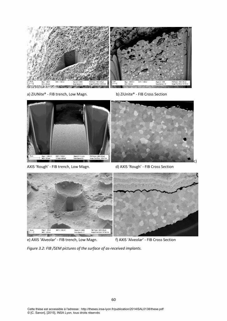
60
a) ZiUNite® - FIB trench, Low Magn. b) ZiUnite® - FIB Cross Section
c)
AXIS ‘Rough’ - FIB trench, Low Magn. d) AXIS ‘Rough’ - FIB Cross Section
e) AXIS ‘Alveolar’ - FIB trench, Low Magn. f) AXIS ‘Alveolar’ - FIB Cross Section
Figure 3.2: FIB /SEM pictures of the surface of as-received implants.
Cette thèse est accessible à l'adresse : http://theses.insa-lyon.fr/publication/2014ISAL0138/these.pdf © [C. Sanon], [2015], INSA Lyon, tous droits réservés
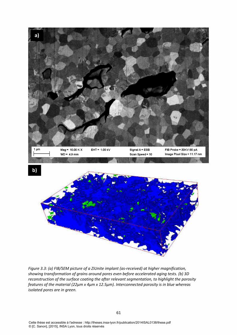
61
Figure 3.3: (a) FIB/SEM picture of a ZiUnite implant (as-received) at higher magnification, showing transformation of grains around pores even before accelerated aging tests. (b) 3D reconstruction of the surface coating the after relevant segmentation, to highlight the porosity features of the material (22μm x 4μm x 12.5μm). Interconnected porosity is in blue whereas isolated pores are in green.
a)
b)
Cette thèse est accessible à l'adresse : http://theses.insa-lyon.fr/publication/2014ISAL0138/these.pdf © [C. Sanon], [2015], INSA Lyon, tous droits réservés
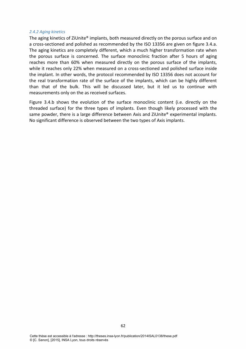
62
2.4.2 Aging kinetics
The aging kinetics of ZiUnite® implants, both measured directly on the porous surface and on a cross-sectioned and polished as recommended by the ISO 13356 are given on figure 3.4.a. The aging kinetics are completely different, which a much higher transformation rate when the porous surface is concerned. The surface monoclinic fraction after 5 hours of aging reaches more than 60% when measured directly on the porous surface of the implants, while it reaches only 22% when measured on a cross-sectioned and polished surface inside the implant. In other words, the protocol recommended by ISO 13356 does not account for the real transformation rate of the surface of the implants, which can be highly different than that of the bulk. This will be discussed later, but it led us to continue with measurements only on the as received surfaces.
Figure 3.4.b shows the evolution of the surface monoclinic content (i.e. directly on the threaded surface) for the three types of implants. Even though likely processed with the same powder, there is a large difference between Axis and ZiUnite® experimental implants. No significant difference is observed between the two types of Axis implants.
Cette thèse est accessible à l'adresse : http://theses.insa-lyon.fr/publication/2014ISAL0138/these.pdf © [C. Sanon], [2015], INSA Lyon, tous droits réservés
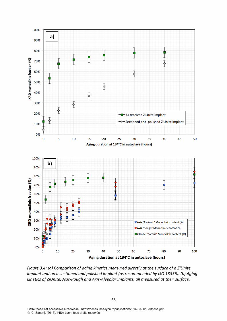
63
Figure 3.4: (a) Comparison of aging kinetics measured directly at the surface of a ZiUnite implant and on a sectioned and polished implant (as recommended by ISO 13356). (b) Aging kinetics of ZiUnite, Axis-Rough and Axis-Alveolar implants, all measured at their surface.
a)
b)
Cette thèse est accessible à l'adresse : http://theses.insa-lyon.fr/publication/2014ISAL0138/these.pdf © [C. Sanon], [2015], INSA Lyon, tous droits réservés
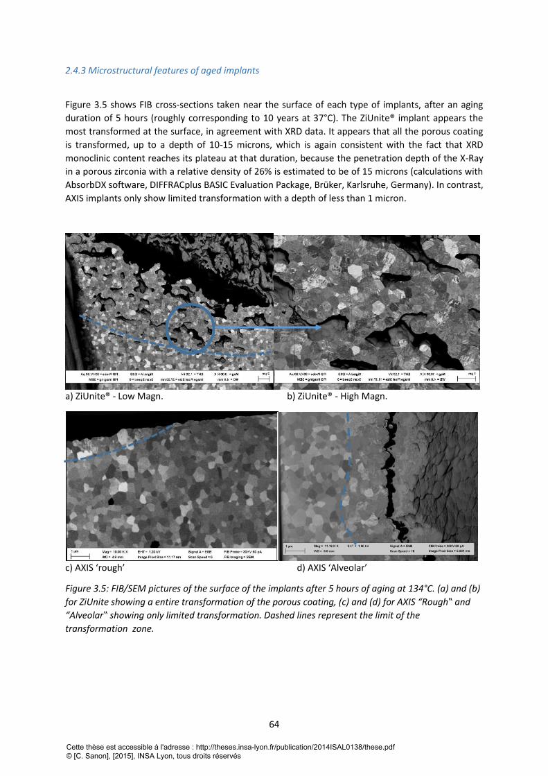
64
2.4.3 Microstructural features of aged implants
Figure 3.5 shows FIB cross-sections taken near the surface of each type of implants, after an aging
duration of 5 hours (roughly corresponding to 10 years at 37°C). The ZiUnite® implant appears the
most transformed at the surface, in agreement with XRD data. It appears that all the porous coating
is transformed, up to a depth of 10-15 microns, which is again consistent with the fact that XRD
monoclinic content reaches its plateau at that duration, because the penetration depth of the X-Ray
in a porous zirconia with a relative density of 26% is estimated to be of 15 microns (calculations with
AbsorbDX software, DIFFRACplus BASIC Evaluation Package, Brüker, Karlsruhe, Germany). In contrast,
AXIS implants only show limited transformation with a depth of less than 1 micron.
a) ZiUnite® - Low Magn. b) ZiUnite® - High Magn.
c) AXIS ‘rough’ d) AXIS ‘Alveolar’
Figure 3.5: FIB/SEM pictures of the surface of the implants after 5 hours of aging at 134°C. (a) and (b)
for ZiUnite showing a entire transformation of the porous coating, (c) and (d) for AXIS “Rough‟ and
“Alveolar‟ showing only limited transformation. Dashed lines represent the limit of the
transformation zone.
Cette thèse est accessible à l'adresse : http://theses.insa-lyon.fr/publication/2014ISAL0138/these.pdf © [C. Sanon], [2015], INSA Lyon, tous droits réservés
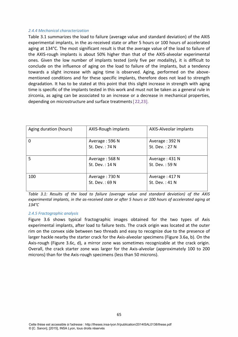
65
2.4.4 Mechanical characterization
Table 3.1 summarizes the load to failure (average value and standard deviation) of the AXIS experimental implants, in the as-received state or after 5 hours or 100 hours of accelerated aging at 134°C. The most significant result is that the average value of the load to failure of the AXIS-rough implants is about 50% higher than that of the AXIS-alveolar experimental ones. Given the low number of implants tested (only five per modality), it is difficult to conclude on the influence of aging on the load to failure of the implants, but a tendency towards a slight increase with aging time is observed. Aging, performed on the above-mentioned conditions and for these specific implants, therefore does not lead to strength degradation. It has to be stated at this point that this slight increase in strength with aging time is specific of the implants tested in this work and must not be taken as a general rule in zirconia, as aging can be associated to an increase or a decrease in mechanical properties,
depending on microstructure and surface treatments 22,23.
Aging duration (hours) AXIS-Rough implants AXIS-Alveolar implants
0 Average : 596 N St. Dev. : 74 N
Average : 392 N St. Dev. : 27 N
5 Average : 568 N St. Dev. : 14 N
Average : 431 N St. Dev. : 59 N
100 Average : 730 N St. Dev. : 69 N
Average : 417 N St. Dev. : 41 N
Table 3.1: Results of the load to failure (average value and standard deviation) of the AXIS experimental implants, in the as-received state or after 5 hours or 100 hours of accelerated aging at 134°C
2.4.5 Fractographic analysis
Figure 3.6 shows typical fractographic images obtained for the two types of Axis experimental implants, after load to failure tests. The crack origin was located at the outer rim on the convex side between two threads and easy to recognize due to the presence of larger hackle nearby the starter crack for the Axis-alveolar specimens (Figure 3.6a, b). On the Axis-rough (Figure 3.6c, d), a mirror zone was sometimes recognizable at the crack origin. Overall, the crack starter zone was larger for the Axis-alveolar (approximately 100 to 200 microns) than for the Axis-rough specimens (less than 50 microns).
Cette thèse est accessible à l'adresse : http://theses.insa-lyon.fr/publication/2014ISAL0138/these.pdf © [C. Sanon], [2015], INSA Lyon, tous droits réservés
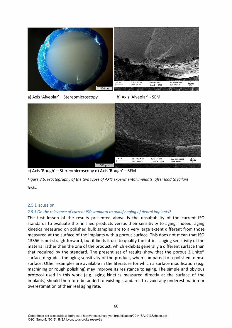
66
a) Axis ‘Alveolar’ – Stereomicroscopy b) Axis ‘Alveolar’ - SEM
c) Axis ‘Rough’ – Stereomicroscopy d) Axis ‘Rough’ – SEM
Figure 3.6: Fractography of the two types of AXIS experimental implants, after load to failure
tests.
2.5 Discussion
2.5.1 On the relevance of current ISO standard to qualify aging of dental implants?
The first lesson of the results presented above is the unsuitability of the current ISO standards to evaluate the finished products versus their sensitivity to aging. Indeed, aging kinetics measured on polished bulk samples are to a very large extent different from those measured at the surface of the implants with a porous surface. This does not mean that ISO 13356 is not straightforward, but it limits it use to qualify the intrinsic aging sensitivity of the material rather than the one of the product, which exhibits generally a different surface than that required by the standard. The present set of results show that the porous ZiUnite® surface degrades the aging sensitivity of the product, when compared to a polished, dense surface. Other examples are available in the literature for which a surface modification (e.g. machining or rough polishing) may improve its resistance to aging. The simple and obvious protocol used in this work (e.g. aging kinetics measured directly at the surface of the implants) should therefore be added to existing standards to avoid any underestimation or overestimation of their real aging rate.
Cette thèse est accessible à l'adresse : http://theses.insa-lyon.fr/publication/2014ISAL0138/these.pdf © [C. Sanon], [2015], INSA Lyon, tous droits réservés
67
2.5.2 Effect of surface modification on aging kinetics
As already demonstrated in previous publications, we show that different surface features lead to highly different aging kinetics, in particular at the initial stage of the t-m
transformation 17,24. Dual-Beam FIB/SEM appears once again as a powerful tool to highlight microstructural changes and investigate how the transformation initiates and propagates inside the material. The main origin of the apparent sensitivity of ZiUnite® prototypes to aging is clearly related to the features of the porous zirconia layer. The interconnected porosity offers a path for the transformation to start at every surface accessible by water, so that the overall porous layer can be transformed in a short period of time (even partially in the as received state). This is not captured by XRD, which gives only an integrated average monoclinic content over the penetration depth of the X-Rays (which depends itself to the density /porosity of the surface), and which makes comparisons impossible on the mode of transformation. XRD conducted on flat surfaces might be useful to characterize and qualify a given zirconia against its ‘intrinsic’ stability versus aging, but not to determine how the transformation may proceed for a given type of implant. XRD gives also a convoluted, average value of the monoclinic content over the penetration depth of the X-Rays (which depends on the porosity of the material, by the way). Without
sophisticated techniques (grazing angles) and mathematical de-convolution 25, XRD hardly gives a full picture of the transformation features, while FIB cross-sections give a clear insight on where the transformation starts and how it proceeds. It is recognized that FIB is still not widely spread, and that, even if more time-consuming and more tricky in terms of preparation, very careful cross-sectioning and SEM imaging might be able to give useful insight on how the transformation proceeds in zirconia dental implants.
2.5.2 Effect of surface modification on mechanical properties
The set of results present in this article confirms that some surface modifications may compromise the load to failure of ceramic products, when they lead to an increase of the critical defect size. For the same geometry of implants, the ‘Axis-Alveolar’ prototypes are fractured for a much lower load than the ‘Axis-Rough’ implants, and this is consistent with a larger initial defect size. Starting with the well-known critical stress intensity factor– defect size relation:
(1)
Where KIC is the critical stress intensity factor (or toughness), f the strength and ac the critical defect size, and assuming a similar toughness for both type of Axis implants, the ratio of strength between the two types of implants is given by:
(2)
The Axis implants design being of the same, the ratio can be translated into load to failure:
Pf 1
Pf 2
=ac2
ac1
(3)
Cette thèse est accessible à l'adresse : http://theses.insa-lyon.fr/publication/2014ISAL0138/these.pdf © [C. Sanon], [2015], INSA Lyon, tous droits réservés
68
In the present experimental case, and (considering the defect sizes
estimated with the fractographic analysis), which is highly consistent. The simple protocol of mechanical testing the implants is therefore able to capture the effect of the initial defect size on implants integrity.
2.5.3 Evaluation of the fatigue limit from simple load to failure tests
Zirconia, as all ceramic materials, is sensitive to Slow Crack Growth. In other words, defects can propagate at low rate even if they are submitted to a stress intensity factor below KIC and lead to delayed failure of the implants. Going into details into the mechanisms of SCG is beyond the scope of the present paper, and the reader could refer to existing references, such as [26, 27]. In brief, SCG occurs in the presence of water or body fluid, and may be accelerated by cyclic fatigue. Fortunately, the presence of a threshold stress intensity factor KI0, below which no propagation occurs, has been claimed in several inorganic materials, both by atomic scale modeling and experiments [28, 29]. The value of KIC and KI0 of 3Y-TZP
(with a grain size similar to the materials tested in this work) are K IC = 6.0MPa m and
K I 0 = 3.0MPa m under cyclic fatigue, respectively [29]. The fatigue limit P0 of an implant
could therefore be roughly anticipated from the load to failure Pf by:
(4)
where P0 and σ0 refer to the fatigue load and stress limit respectively, and Pf and σf are the load and stress to failure during fast fracture tests.
In the case of the ‘Axis-Alveolar’ prototypes, the average value of the load to failure is of 396 N, which would mean that roughly 50% of the implants would resist to 198N (and thus 50% would fail), this load value being on the order of the reported average mastication forces
30. Given the limit of the present analysis (especially because there is a variability on the implant position and on the mastication forces), it would anyway certainly show that the risk of failure is too important with this combination of design and surface features. The producer, based on the analysis above, has abandoned this type of implant design associated to the alveolar structure. With a larger number of experimental implants, statistical evaluation (probability of failure) of the delayed failure risk under a given applied load (i.e. under a given clinical situation) could be anticipated by the mechanical tests proposed in this work. It has to be recalled that such tests are not included in current ISO standards for zirconia as material for dental implants. Such tests are easy to run, with simple testing machines, and would give a good first estimation of the fatigue limit of newly developed zirconia dental implants. As far as lifetime under cyclic conditions is concerned, they could be complemented with real cyclic fatigue tests under the same testing geometry.
2.6 Conclusion
Zirconia being sensitive to slow crack growth and aging, it is important to include relevant tests in future protocol to insure long-term performance and safety of dental implants. The present work shows the limit of current ISO 13356 standard to insure the reliability and lifetime of zirconia dental implants and the need to include complementary methods to XRD to follow more in details aging kinetics. New protocols should therefore include:
Cette thèse est accessible à l'adresse : http://theses.insa-lyon.fr/publication/2014ISAL0138/these.pdf © [C. Sanon], [2015], INSA Lyon, tous droits réservés
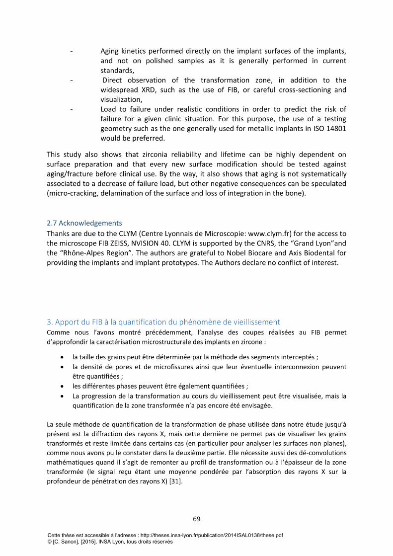
69
- Aging kinetics performed directly on the implant surfaces of the implants, and not on polished samples as it is generally performed in current standards,
- Direct observation of the transformation zone, in addition to the widespread XRD, such as the use of FIB, or careful cross-sectioning and visualization,
- Load to failure under realistic conditions in order to predict the risk of failure for a given clinic situation. For this purpose, the use of a testing geometry such as the one generally used for metallic implants in ISO 14801 would be preferred.
This study also shows that zirconia reliability and lifetime can be highly dependent on surface preparation and that every new surface modification should be tested against aging/fracture before clinical use. By the way, it also shows that aging is not systematically associated to a decrease of failure load, but other negative consequences can be speculated (micro-cracking, delamination of the surface and loss of integration in the bone).
2.7 Acknowledgements
Thanks are due to the CLYM (Centre Lyonnais de Microscopie: www.clym.fr) for the access to the microscope FIB ZEISS, NVISION 40. CLYM is supported by the CNRS, the “Grand Lyon”and the “Rhône-Alpes Region”. The authors are grateful to Nobel Biocare and Axis Biodental for providing the implants and implant prototypes. The Authors declare no conflict of interest.
3. Apport du FIB à la quantification du phénomène de vieillissement Comme nous l’avons montré précédemment, l’analyse des coupes réalisées au FIB permet
d’approfondir la caractérisation microstructurale des implants en zircone :
la taille des grains peut être déterminée par la méthode des segments interceptés ;
la densité de pores et de microfissures ainsi que leur éventuelle interconnexion peuvent
être quantifiées ;
les différentes phases peuvent être également quantifiées ;
La progression de la transformation au cours du vieillissement peut être visualisée, mais la
quantification de la zone transformée n’a pas encore été envisagée.
La seule méthode de quantification de la transformation de phase utilisée dans notre étude jusqu’à
présent est la diffraction des rayons X, mais cette dernière ne permet pas de visualiser les grains
transformés et reste limitée dans certains cas (en particulier pour analyser les surfaces non planes),
comme nous avons pu le constater dans la deuxième partie. Elle nécessite aussi des dé-convolutions
mathématiques quand il s’agit de remonter au profil de transformation ou à l’épaisseur de la zone
transformée (le signal reçu étant une moyenne pondérée par l’absorption des rayons X sur la
profondeur de pénétration des rayons X) [31].
Cette thèse est accessible à l'adresse : http://theses.insa-lyon.fr/publication/2014ISAL0138/these.pdf © [C. Sanon], [2015], INSA Lyon, tous droits réservés
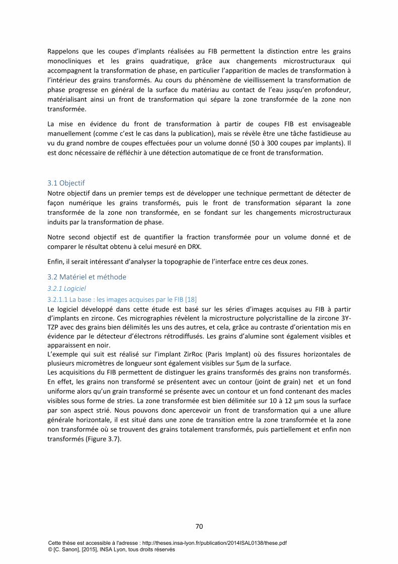
70
Rappelons que les coupes d’implants réalisées au FIB permettent la distinction entre les grains
monocliniques et les grains quadratique, grâce aux changements microstructuraux qui
accompagnent la transformation de phase, en particulier l’apparition de macles de transformation à
l’intérieur des grains transformés. Au cours du phénomène de vieillissement la transformation de
phase progresse en général de la surface du matériau au contact de l’eau jusqu’en profondeur,
matérialisant ainsi un front de transformation qui sépare la zone transformée de la zone non
transformée.
La mise en évidence du front de transformation à partir de coupes FIB est envisageable
manuellement (comme c’est le cas dans la publication), mais se révèle être une tâche fastidieuse au
vu du grand nombre de coupes effectuées pour un volume donné (50 à 300 coupes par implants). Il
est donc nécessaire de réfléchir à une détection automatique de ce front de transformation.
3.1 Objectif Notre objectif dans un premier temps est de développer une technique permettant de détecter de
façon numérique les grains transformés, puis le front de transformation séparant la zone
transformée de la zone non transformée, en se fondant sur les changements microstructuraux
induits par la transformation de phase.
Notre second objectif est de quantifier la fraction transformée pour un volume donné et de
comparer le résultat obtenu à celui mesuré en DRX.
Enfin, il serait intéressant d’analyser la topographie de l’interface entre ces deux zones.
3.2 Matériel et méthode
3.2.1 Logiciel
3.2.1.1 La base : les images acquises par le FIB [18]
Le logiciel développé dans cette étude est basé sur les séries d’images acquises au FIB à partir d’implants en zircone. Ces micrographies révèlent la microstructure polycristalline de la zircone 3Y-TZP avec des grains bien délimités les uns des autres, et cela, grâce au contraste d’orientation mis en évidence par le détecteur d’électrons rétrodiffusés. Les grains d’alumine sont également visibles et apparaissent en noir. L’exemple qui suit est réalisé sur l’implant ZirRoc (Paris Implant) où des fissures horizontales de plusieurs micromètres de longueur sont également visibles sur 5µm de la surface. Les acquisitions du FIB permettent de distinguer les grains transformés des grains non transformés.
En effet, les grains non transformé se présentent avec un contour (joint de grain) net et un fond
uniforme alors qu’un grain transformé se présente avec un contour et un fond contenant des macles
visibles sous forme de stries. La zone transformée est bien délimitée sur 10 à 12 μm sous la surface
par son aspect strié. Nous pouvons donc apercevoir un front de transformation qui a une allure
générale horizontale, il est situé dans une zone de transition entre la zone transformée et la zone
non transformée où se trouvent des grains totalement transformés, puis partiellement et enfin non
transformés (Figure 3.7).
Cette thèse est accessible à l'adresse : http://theses.insa-lyon.fr/publication/2014ISAL0138/these.pdf © [C. Sanon], [2015], INSA Lyon, tous droits réservés
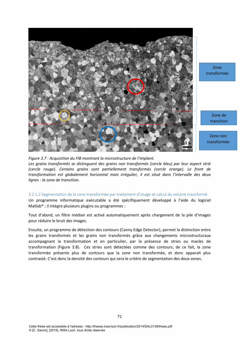
71
Figure 3.7 : Acquisition du FIB montrant la microstructure de l’implant. Les grains transformés se distinguent des grains non transformés (cercle bleu) par leur aspect strié (cercle rouge). Certains grains sont partiellement transformés (cercle orange). Le front de transformation est globalement horizontal mais irrégulier, il est situé dans l’intervalle des deux lignes : la zone de transition.
3.2.1.2 Segmentation de la zone transformée par traitement d’image et calcul du volume transformé
Un programme informatique exécutable a été spécifiquement développé à l’aide du logiciel
Matlab® ; il intègre plusieurs plugins ou programmes :
Tout d’abord, un filtre médian est activé automatiquement après chargement de la pile d’images
pour réduire le bruit des images.
Ensuite, un programme de détection des contours (Canny Edge Detector), permet la distinction entre
les grains transformés et les grains non transformés grâce aux changements microstructuraux
accompagnant la transformation et en particulier, par la présence de stries ou macles de
transformation (Figure 3.8). Ces stries sont détectées comme des contours, de ce fait, la zone
transformée présente plus de contours que la zone non transformée, et donc apparait plus
contrasté. C’est donc la densité des contours qui sera le critère de segmentation des deux zones.
1 µ
Zone
transformée
Zone de
transition
Zone non
transformée
Cette thèse est accessible à l'adresse : http://theses.insa-lyon.fr/publication/2014ISAL0138/these.pdf © [C. Sanon], [2015], INSA Lyon, tous droits réservés
72
Figure 3.8 : Image traité par le module de détection de contours « Canny edge detector ». Les deux zones se distinguent aisément par la différence de densité de contour créant un contraste.
L’amplification du contraste est faite par une série d’érosions et de dilatations (Figure 3.9).
Figure 3.9 : Résultats obtenues au cours des opérations d’érosion et de dilatation.
Cette thèse est accessible à l'adresse : http://theses.insa-lyon.fr/publication/2014ISAL0138/these.pdf © [C. Sanon], [2015], INSA Lyon, tous droits réservés
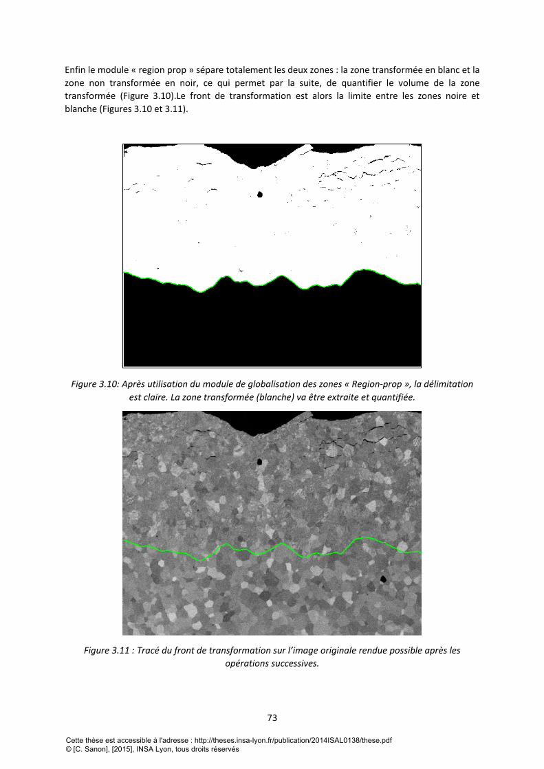
73
Enfin le module « region prop » sépare totalement les deux zones : la zone transformée en blanc et la
zone non transformée en noir, ce qui permet par la suite, de quantifier le volume de la zone
transformée (Figure 3.10).Le front de transformation est alors la limite entre les zones noire et
blanche (Figures 3.10 et 3.11).
Figure 3.10: Après utilisation du module de globalisation des zones « Region-prop », la délimitation
est claire. La zone transformée (blanche) va être extraite et quantifiée.
Figure 3.11 : Tracé du front de transformation sur l’image originale rendue possible après les
opérations successives.
Cette thèse est accessible à l'adresse : http://theses.insa-lyon.fr/publication/2014ISAL0138/these.pdf © [C. Sanon], [2015], INSA Lyon, tous droits réservés
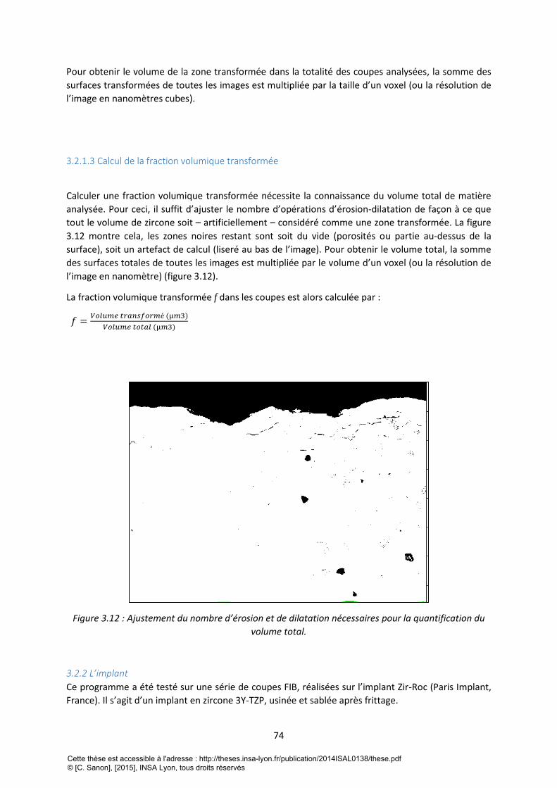
74
Pour obtenir le volume de la zone transformée dans la totalité des coupes analysées, la somme des
surfaces transformées de toutes les images est multipliée par la taille d’un voxel (ou la résolution de
l’image en nanomètres cubes).
3.2.1.3 Calcul de la fraction volumique transformée
Calculer une fraction volumique transformée nécessite la connaissance du volume total de matière
analysée. Pour ceci, il suffit d’ajuster le nombre d’opérations d’érosion-dilatation de façon à ce que
tout le volume de zircone soit – artificiellement – considéré comme une zone transformée. La figure
3.12 montre cela, les zones noires restant sont soit du vide (porosités ou partie au-dessus de la
surface), soit un artefact de calcul (liseré au bas de l’image). Pour obtenir le volume total, la somme
des surfaces totales de toutes les images est multipliée par le volume d’un voxel (ou la résolution de
l’image en nanomètre) (figure 3.12).
La fraction volumique transformée f dans les coupes est alors calculée par :
𝑓 =𝑉𝑜𝑙𝑢𝑚𝑒 𝑡𝑟𝑎𝑛𝑠𝑓𝑜𝑟𝑚é (µ𝑚3)
𝑉𝑜𝑙𝑢𝑚𝑒 𝑡𝑜𝑡𝑎𝑙 (µ𝑚3)
Figure 3.12 : Ajustement du nombre d’érosion et de dilatation nécessaires pour la quantification du
volume total.
3.2.2 L’implant
Ce programme a été testé sur une série de coupes FIB, réalisées sur l’implant Zir-Roc (Paris Implant,
France). Il s’agit d’un implant en zircone 3Y-TZP, usinée et sablée après frittage.
Cette thèse est accessible à l'adresse : http://theses.insa-lyon.fr/publication/2014ISAL0138/these.pdf © [C. Sanon], [2015], INSA Lyon, tous droits réservés
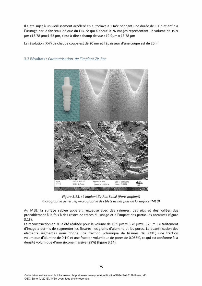
75
Il a été sujet à un vieillissement accéléré en autoclave à 134°c pendant une durée de 100h et enfin à
l’usinage par le faisceau ionique du FIB, ce qui a abouti à 76 images représentant un volume de 19.9
µm x13.78 µmx1.52 µm, c’est-à-dire : champ de vue : 19.9µm x 13.78 µm
La résolution (X-Y) de chaque coupe est de 20 nm et l’épaisseur d’une coupe est de 20nm
3.3 Résultats : Caractérisation de l’implant Zir-Roc
Figure 3.13. : L’implant Zir Roc Sablé (Paris Implant) Photographie générale, micrographie des filets usinés puis de la surface (MEB).
Au MEB, la surface sablée apparait rugueuse avec des rainures, des pics et des vallées dus probablement à la fois à des restes de traces d’usinage et à l’impact des particules abrasives (figure 3.13). La reconstruction en 3D a été réalisée pour le volume de 19.9 µm x13.78 µmx1.52 µm. Le traitement d’image a permis de segmenter les fissures, les grains d’alumine et les pores. La quantification des éléments segmentés nous donne une fraction volumique de fissures de 0.4% ; une fraction volumique d’alumine de 0.1% et une fraction volumique de pores de 0.056%, ce qui est conforme à la densité volumique d’une zircone massive (99%) (figure 3.14).
Cette thèse est accessible à l'adresse : http://theses.insa-lyon.fr/publication/2014ISAL0138/these.pdf © [C. Sanon], [2015], INSA Lyon, tous droits réservés
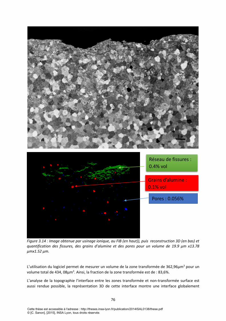
76
Figure 3.14 : Image obtenue par usinage ionique, au FIB (en haut)), puis reconstruction 3D (en bas) et quantification des fissures, des grains d’alumine et des pores pour un volume de 19.9 µm x13.78 µmx1.52 µm. L’utilisation du logiciel permet de mesurer un volume de la zone transformée de 362,96µm3 pour un
volume total de 434, 08µm3. Ainsi, la fraction de la zone transformée est de : 83,6%.
L’analyse de la topographie l’interface entre les zones transformée et non-transformée surface est
aussi rendue possible, la représentation 3D de cette interface montre une interface globalement
1 µ
Réseau de fissures :
0.4% vol
Grains d’alumine :
0.1% vol
Pores : 0.056%
Cette thèse est accessible à l'adresse : http://theses.insa-lyon.fr/publication/2014ISAL0138/these.pdf © [C. Sanon], [2015], INSA Lyon, tous droits réservés
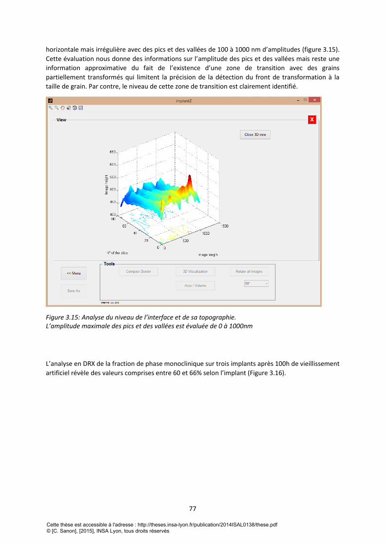
77
horizontale mais irrégulière avec des pics et des vallées de 100 à 1000 nm d’amplitudes (figure 3.15).
Cette évaluation nous donne des informations sur l’amplitude des pics et des vallées mais reste une
information approximative du fait de l’existence d’une zone de transition avec des grains
partiellement transformés qui limitent la précision de la détection du front de transformation à la
taille de grain. Par contre, le niveau de cette zone de transition est clairement identifié.
Figure 3.15: Analyse du niveau de l’interface et de sa topographie. L’amplitude maximale des pics et des vallées est évaluée de 0 à 1000nm
L’analyse en DRX de la fraction de phase monoclinique sur trois implants après 100h de vieillissement
artificiel révèle des valeurs comprises entre 60 et 66% selon l’implant (Figure 3.16).
Cette thèse est accessible à l'adresse : http://theses.insa-lyon.fr/publication/2014ISAL0138/these.pdf © [C. Sanon], [2015], INSA Lyon, tous droits réservés
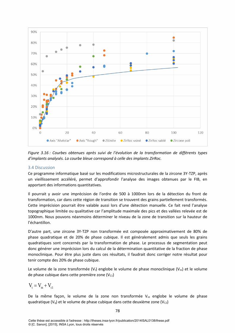
78
Figure 3.16 : Courbes obtenues après suivi de l’évolution de la transformation de différents types
d’implants analysés. La courbe bleue correspond à celle des implants ZirRoc.
3.4 Discussion Ce programme informatique basé sur les modifications microstructurales de la zircone 3Y-TZP, après
un vieillissement accéléré, permet d’approfondir l’analyse des images obtenues par le FIB, en
apportant des informations quantitatives.
Il pourrait y avoir une imprécision de l’ordre de 500 à 1000nm lors de la détection du front de
transformation, car dans cette région de transition se trouvent des grains partiellement transformés.
Cette imprécision pourrait être valable aussi lors d’une détection manuelle. Ce fait rend l’analyse
topographique limitée ou qualitative car l’amplitude maximale des pics et des vallées relevée est de
1000nm. Nous pouvons néanmoins déterminer le niveau de la zone de transition sur la hauteur de
l’échantillon.
D’autre part, une zircone 3Y-TZP non transformée est composée approximativement de 80% de
phase quadratique et de 20% de phase cubique. Il est généralement admis que seuls les grains
quadratiques sont concernés par la transformation de phase. Le processus de segmentation peut
donc générer une imprécision lors du calcul de la détermination quantitative de la fraction de phase
monoclinique. Pour être plus juste dans ces résultats, il faudrait donc corriger notre résultat pour
tenir compte des 20% de phase cubique.
Le volume de la zone transformée (Vt) englobe le volume de phase monoclinique (Vm) et le volume
de phase cubique dans cette première zone (VC1)
t m c1V V V
De la même façon, le volume de la zone non transformée Vnt englobe le volume de phase
quadratique (Vq) et le volume de phase cubique dans cette deuxième zone (VC2)
Cette thèse est accessible à l'adresse : http://theses.insa-lyon.fr/publication/2014ISAL0138/these.pdf © [C. Sanon], [2015], INSA Lyon, tous droits réservés
79
nt q c2V V V
En appelant FC le taux volumique de phase cubique (en première approximation constant dans les 2
zones), on obtient :
c1c
m c1
VF
V V
, d’où on tire c
c1 m
c
FV V
1 F
.
De la même manière, cc2 q
c
FV V
1 F
Et donc, la fraction volumique transformée (ft) calculée par le logiciel est :
t m
cm
c
c cm
c c
c1t
t nt m c1 q c2
q
FV 1
1 F
F FV 1 V 1
1 F 1 F
V V Vf
V V V V V V
et donc :
mt
m q
Vf
V V
D’autre part, la fraction de phase monoclinique obtenue en diffraction des rayons X (fm,DRX) est
donnée par :
mm,DRX
m q c
Vf
V V V
Où VC est le volume total de phase cubique (Vc=Vc1+Vc2). D’après les équations précédentes, on a
cc c1 c2 m q
c
FV V V V V
1 F
On en déduit donc que :
c mmm,DRX
c m qm q m q
c
1 F VVf
F V VV V V V
1 F
Ainsi, la relation entre la fraction volumique de la zone transformée (ft) calculée par le logiciel et la
fraction volumique de phase monoclinique (fm, DRX) calculée par diffraction des rayons X est donnée
par : m,DRX c tf 1 F f
La fraction transformée calculée à partir du logiciel doit donc être multipliée par (1-Fc) (où Fc est la
fraction de phase cubique dans le matériau, ici 20%) pour être comparable à la fraction de phase
monoclinique telle que mesurée par DRX. On obtient donc ici une fraction corrigée de phase
monoclinique de 83%x(1-0,2) = 66,4%.
Cette thèse est accessible à l'adresse : http://theses.insa-lyon.fr/publication/2014ISAL0138/these.pdf © [C. Sanon], [2015], INSA Lyon, tous droits réservés
80
Pour obtenir un résultat plus précis encore, il faudrait également corriger les effets d’absorption des
Rayons X dans la matière, qui font que les zones les plus profondes sont moins prises en compte dans
le signal total, et s’assurer que la profondeur des coupes FIB est cohérente avec la profondeur
analysée en diffraction X, ce qui n’est pas tout à fait le cas ici (on peut estimer que, dans la zircone,
90% du signal en DRX provient des 5 premiers microns sous la surface, alors que la zone analysée en
FIB a une profondeur d’environ 10 µm)
La valeur de fraction transformée après soustraction des 20% de phase cubique de la zone
transformée est donc cohérente à celle mesurée en DRX. Cependant, le volume usiné par le FIB étant
faible, nous ne pouvons pas généraliser à ce stade la cohérence de ce résultat, plusieurs essais sont
nécessaires pour cela.
Cela ouvre néanmoins des perspectives intéressantes pour l’association de ces deux méthodes de
quantification.
3.5 Conclusion L’utilisation d’une méthodologie associant les techniques de caractérisation des sciences des
matériaux (FIB, DRX) et les techniques de traitement d’image, ont permis d’approfondir la
caractérisation du vieillissement des implants dentaires en zircone 3Y-TZP et d’obtenir pour cet
exemple, une corrélation entre la technique du FIB qui permet de visualiser la transformation de
phase ainsi que l’épaisseur transformé sur un échantillon et le DRX qui permet l’analyse
cristallographique des différentes phases.
4 References bibliographique de la troisième partie 1 Branemark P I. Osseointegration and its experimental background. The Journal of prosthetic
dentistry,1983;50:(3), 399-410.
2 Babbush CA, Hahn JA, Krauser JT, Rosenlicht JL. Dental implants: the art and science. Maryland
Heights: Saunders/Elsevier ; 2011.
3 Karoussis I K, Salvi GE, Heitz-Mayfield LJA, Brägger U, Hämmerle CHF, Lang NP. Long-term implant
prognosis in patients with and without a history of chronic periodontitis: a 10-year prospective
cohort study of the ITI® Dental Implant System. Clin Oral Implants Res 2003;14 (3): 329-39.
4 Dunn DB. The use of a zirconia custom implant-supported fixed partial denture prosthesis to treat
implant failure in the anterior maxilla: a clinical report. Journal of Prosthetic Dentistry 2008;100:415–
21
5 Vamanu, C. I., Høl, P. J., Allouni, Z. E., Elsayed, S., & Gjerdet, N. R. (2008). Formation of potential
titanium antigens based on protein binding to titanium dioxide nanoparticles. International journal of
nanomedicine, 3(1), 69.
6 Sicilia, A., Cuesta, S., Coma, G., Arregui, I., Guisasola, C., Ruiz, E., & Maestro, A. (2008). Titanium
allergy in dental implant patients: a clinical study on 1500 consecutive patients. Clinical oral implants
research, 19(8), 823-835.
7 Oliva, J., Oliva, X., & Oliva, J. D. (2009). Five-year success rate of 831 consecutively placed Zirconia
dental implants in humans: a comparison of three different rough surfaces. The International journal
of oral & maxillofacial implants, 25(2), 336-344.
Cette thèse est accessible à l'adresse : http://theses.insa-lyon.fr/publication/2014ISAL0138/these.pdf © [C. Sanon], [2015], INSA Lyon, tous droits réservés
81
8Manicone, P. F., Rossi Iommetti, P., & Raffaelli, L. (2007). An overview of zirconia ceramics: basic
properties and clinical applications. Journal of dentistry, 35(11), 819-826.
9 Gahlert M, Gudehus T, Eichhorn S, Steinhauser E, Kniha H, Erhardt W. Biomechanical and
histomorphometric comparison between zirconia implants with varying surface textures and a
titanium implant in the maxilla of miniature pigs. Clin Oral Implants Res 2007 ; 18 (5) : 662-8.
10 Scarano A, Piattelli M, Caputi S, Favero GA, Piattelli A. Bacterial adhesion on commercially pure
titanium and zirconium oxide disks: an in vivo human study. J Periodontol 2004 ; 75 (2) : 292-6.
11 Sennerby L, Dasmah A, Larsson B, Iverhed M. Bone tissue responses to surface-modified zirconia
implants: a histomorphometric and removal torque study in the rabbit. Clinical Implant Dentistry and
Related Research 2005;7:13–20, 2005.
12 Depprich R, Zipprich H, Ommerborn M, Naujoks C, Wiesmann HP, Kiattavorncharoen S, et al.,
Meyer U, Handschel J. Osseointegration of zirconia implants compared with titanium: an in vivo
study. Head and Face Medicine 2008;4, art. 30.
13 Yamashita D, Machigashira M, Miyamoto M, Takeuchi H, Noguchi K, Izumi Y, et al. Effect of
surface roughness on initial responses of osteoblast-like cells on two types of zirconia. Dental
Materials Journal 2009;28:461–70.
14 Ullman, D. G. (1992). The mechanical design process (Vol. 2). New York: McGraw-Hill.
15 Chevalier J, Gremillard L, Virkar A, Clarke DR. The tetragonal-monoclinic transformation in
zirconia: lessons learned and future trends. Journal of the American Ceramic Society 2009;92:1901–
20.
16 Garvie, R. C., R. H. Hannink, and R. T. Pascoe. "Ceramic steel?." (1975): 703-704.
17 Chevalier, J., Loh, J., Gremillard, L., Meille, S., & Adolfson, E. (2011). Low-temperature
degradation in zirconia with a porous surface. Acta biomaterialia,7(7), 2986-2993.
18 Sanon C, Chevalier J, Douillard T, Kohal RJ, Coelho PG, Hjerppe J, Silva NRFA. Low temperature
degradation and reliability of one-piece ceramic oral implants with a porous surface. Dent Mater
2013; 29 (4) : 389-97.
19 ISO 13356:2008. Implants for surgery -- Ceramic materials based on yttria-stabilized tetragonal
zirconia (Y-TZP).
20 Chevalier J, Gremillard L, Deville S. Low-temperature degradation of zirconia and implications for
biomedical implants. Annual Review of Materials Research 2007;37:1–32.
21 ISO 14801:2007. Dentistry -- Implants -- Dynamic fatigue test for endosseous dental implants.
22 Kosmač, T., Oblak, C., Marion, L. The effects of dental grinding and sandblasting on ageing and
fatigue behavior of dental zirconia (Y-TZP) ceramic, Journal of the European Ceramic Society, 2008,
28 (5), pp. 1085-1090.
23 Marro, F.G., Mestra, A., Anglada, M. Weibull strength statistics of hydrothermally aged 3 mol%
yttria-stabilised tetragonal zirconia (2014) Ceramics International, 40 (8 PART B), pp. 12777-12782.
24 Deville S, Chevalier J, Gremillard L. Influence of surface finish and residual stresses on the ageing
sensitivity of biomedical grade zirconia. Biomaterials 2006 ; 27(10) : 2186-2192.
Cette thèse est accessible à l'adresse : http://theses.insa-lyon.fr/publication/2014ISAL0138/these.pdf © [C. Sanon], [2015], INSA Lyon, tous droits réservés
82
25 Gremillard, L., Grandjean, S., Chevalier, J. A new method to measure monoclinic depth profde in
zirconia-based ceramics from X-ray diffraction data. Journal of Materials Research
2010, 101 (1), pp. 88-94.
26 B. R. Lawn, Fracture of Brittle solids. 2n ed. 1993, Cambridge: Cambridge University Press.
27 C. Olagnon, J. Chevalier, and V. Pauchard, Global description of crack propagation in ceramics.
Journal of the European Ceramic Society, 2006. 26: 3051-2059.
28 Zhu T, Li J, Lin X and Yip S Stress-dependent molecular pathways of silica–water reaction J.
Mech. Phys. Solids, 2005, 53 : 1597–623.
29 Chevalier, J., Aza, A. H. D., Fantozzi, G., Schehl, M. and Torrecillas, R., Extending the Lifetime of
Ceramic Orthopaedic Implants. Adv. Mater., 2000, 12: 1619–1621.
30 Andreiotelli, M., Wenz, H. J., & Kohal, R. J. (2009). Are ceramic implants a viable alternative to
titanium implants? A systematic literature review. Clinical Oral Implants Research, 2010, 20(s4), 32-
47.
[31] Gremillard et al. International Journal of Materials Research, 2010,101 (1), pp. 88-94)
Cette thèse est accessible à l'adresse : http://theses.insa-lyon.fr/publication/2014ISAL0138/these.pdf © [C. Sanon], [2015], INSA Lyon, tous droits réservés
83
QUATRIEME PARTIE: MISE EN EVIDENCE DU PHENOMENE DE VIEILLISSEMENT
IN VIVO
1 Introduction Dans cette quatrième partie, l’analyse d’explants issus d’essais cliniques, en particulier à l’aide des
technologies d’imagerie numérique présentées dans la partie précédente, permet de mettre en
évidence, pour la première fois sur des implants dentaires, l’occurrence effective du mécanisme de
vieillissement in vivo.
Cette quatrième partie est présentée sous la forme d’un projet d’article dont la soumission est
prévue prochainement.
2 “Study of a type of 3Y-TZP zirconia dental implant presenting in vivo accelerated
aging”
2.1 Abstract
Introduction. The standard material in oral implantology is the biomedical grade titanium. However,
aesthetic considerations and contemporary demand for metal free materials in dentistry have
catalyzed the search for alternatives to titanium.
Yttria-stabilised zirconia implants have been proposed since the 2000 years, because of its tooth-like
color associated to its high mechanical properties for a ceramic and its excellent biocompatibility.
Moreover, several animal studies show that zirconia implants exhibit an osseointegration
comparable to titanium implants.
In order to favor bone in-growth and osseointegration, surface treatments may be applied to zirconia
implants. Among them, the most common are sandblasting, acid-etching, and deposition of a porous
coating or using surface-structured molds. If surface modification improve bone in-growth, they
could also impact the stability of the tetragonal phase under humid atmosphere. It has been shown,
already in the 80’s, that zirconia could transform with time in the presence of water (i.e. at the
surface). This phenomenon called “Low Temperature Degradation” (LTD) or “aging”, can lead in
certain cases to micro-cracking and could reduce the lifetime of zirconia implant. In vitro studies have
recently highlighted the occurrence of LTD on zirconia dental implants [1] but the scientific backup
on the LTD in vivo of such implants is non-existent although this phenomenon have led to series of
failure of femoral heads made of Yttria-stabilised zirconia in the early 2000s. This paper shows that
LTD could occur in vivo for a specific type of zirconia dental implants.
Experimental. As received 3Y-TZP dental implants with porous coating and explanted implants of the
same type were assessed. The as-received implants were first characterized by Scanning Electron
Microscopy (SEM), X-Ray Diffraction (XRD), and Focused Ion Beam (FIB) enabling 3D reconstruction.
Accelerated aging was performed on these implants and the evolution of monoclinic content with
time followed by XRD. The implants were then characterized again after aging by FIB and XRD.
Explanted implants were characterized by SEM, FIB and XRD. Osseointegrated areas were
characterized by Optical Microscopy (OM), FIB and EDX (Energy Dispersive X-ray spectrometry). A
Cette thèse est accessible à l'adresse : http://theses.insa-lyon.fr/publication/2014ISAL0138/these.pdf © [C. Sanon], [2015], INSA Lyon, tous droits réservés
84
specific Matlab® software was developed to highlight and quantify the thickness of the
transformation zone on the explanted implants.
Results and discussions. The series of tests done on as received implants shows that the porous
coating accelerates LTD. Explanted implants present a residual coating, which is completely
transformed and highly micro-cracked. Osseointegrated part of implant present also a transformed
zone. DRX quantification and FIB sections highlight the occurrence of accelerated LTD for this specific
case of implants after artificial aging (in vitro) and after few years in vivo.
As each dental implant company has its own process, all zirconia implants may behave differently,
even if the composition is the same. Especially, surface modifications can have a large influence on
the kinetic of LTD and could lead, in certain case to a loss of osseointegration after few years of use.
2.2 Introduction Oral implants offer an effective treatment for replacement of missing teeth. Since the pioneering
works of Brånemark in the 60‟s [1], several millions of titanium implants have been produced. It is
reported that the oral implant number will grow at a rate of 6% per year from 2010 to 2015, since
there is a tendency to propose more and more implants to patients to improve their quality of life
(aesthetic, but also mastication and long-term stability) [2]. Current long-term clinical investigations
(more than 10 years of follow-up) report very favorable survival rates, which places titanium and its
biomedical alloys as the gold standard [3].
However, in some cases, the greyish color of a titanium implant may be perceived through the peri-
implant mucosa causing some aesthetic drawbacks [4]. Furthermore, in rare cases, metals (including
titanium) may induce sensitization or allergic reactions [5,6]. Finally, some patients also ask for
completely metal-free dental reconstructions. Thus, implants fabricated with ceramic materials are
gaining popularity and might have a certain clinical and industrial success if they prove to be strong
enough, stable over time and well integrated in the jawbone.
Especially, yttria-doped zirconia ceramics (often referred as 3Y-TZP, standing for 3 mol.% Yttria doped
Zirconia Tetragonal Polycristals) are often presented as the alternative to titanium [7]. These
ceramics present the best mechanical properties of all oxide ceramics[8], they also present an
excellent tissue compatibility and show osseointegration comparable to that of titanium [9]. A
further advantage of zirconia is the reduced formation of plaque [10]. Moreover, zirconia exhibits
color properties closely related to teeth for optimal aesthetics in patients with thin gingival biotypes,
which cannot be met using titanium implants.
However, zirconia is a complex material because it is metastable at room temperature [11]. On one
hand, its excellent mechanical properties are due to the transformation of meta-stable tetragonal
grains to the monoclinic phase under stress (for example in the vicinity of a crack). It is accompanied
by a volume expansion and induces compressive stresses that shield the crack tip from the applied
stresses. This phenomenon is known as transformation toughening. On the other hand, this meta-
stability leads to a possible transformation of grains in contact with water (or body fluids) with time.
This phenomenon is often referred to as low temperature degradation (LTD) or aging and conducted
to failure of several orthopedic head in the beginning 2000 year. Aging is a progressive tetragonal to
monoclinic transformation at the surface triggered by water molecules, which often results in surface
modification (roughening) and micro cracking [12] therefore potentially decreasing the
physicochemical and mechanical properties of the device
Cette thèse est accessible à l'adresse : http://theses.insa-lyon.fr/publication/2014ISAL0138/these.pdf © [C. Sanon], [2015], INSA Lyon, tous droits réservés
85
Worldwide, there are more than 10 companies producing zirconia dental implants and each
manufacturer develops its process, its implant design and its own surface features to promote
osseointegration. It is generally accepted that rough surfaces improve osseointegration and favor
mechanical anchorage with bone. Several strategies are explored to process rough or porous surface
implant i.e. machining, acid etching, sandblasting, molding or coating with a porous layer [13-15 ]. As
already demonstrated in vitro [REF], some surface treatments may affect mechanical strength or/and
lead to accelerated aging. Although this could be detrimental for the bone-implant interface, this
critical point is under-emphasized by zirconia dental implants manufacturers.
Nobel Biocare, a dental implants companies which is very implicated in R&D, has developed a
prototype of 3Y-TZP zirconia dental implant coated by a porous surface (ZiUniteTM surface
technology, Nobel Biocare®) which have been the main subject of a series of studies dealing with
several aspects of the implants, mainly microstructural stability, biological behavior and mechanical
behavior. ZiUnite® implants are actually the dental zirconia implants which have been the most
investigated and characterized, by several research laboratories in Europe and USA (France,
Germany, Italy, Sweden, USA). More generally, the extensive work conducted on ZiUnite® has
provided a better understanding of the behavior of zirconia 3Y-TZP materials in dental fields. A
summary of the main results available on ZiUnite® implants is exposed below.
Their mechanical behavior was validated by in vitro thermocyclic tests in aqueous media [16].
Biomechanical and histological studies conducted in animal models have shown the ability of the
porous surface to enhance short-term bone ingrowth after 3 and 6 weeks of healing [17, 18].
However, one year clinical investigations on twenty eight patients [19], shown a high frequency of
increased radiographic bone loss (>2 mm), leading the authors to conclude that these zirconia
implants may perform worse than conventional titanium implants because of the instability of the
bone-implant interface.
It is generally accepted that peri-implant bone loss is a multifactorial phenomenon including such
factors as loading stress and bacterial colonization. Surface metastability of 3Y-TZP material could be
an additional cause of dental implant failure. In vitro microstructural stability of the porous coating
has thus been investigated [20, 21], highlighting the effect of all processing steps on aging kinetics
and fracture strength. In particular, theses in vitro studies shown that the main origin of the apparent
sensitivity of ZiUnite® prototypes to LTD is clearly related to the features of the porous zirconia layer.
The interconnected porosity offers a path for the transformation, which could start at every surface
accessible by water, so that the overall porous layer could be transformed in a short period of time.
After a clinical study conducted by Kohal, several ZiUnite® implants had to be removed due to the
loss of bone-implant interface leading to a high mobility.
The objective of the present study was to assess the role of LTD in the failure of these removed
ZiUnite® implants (or explants).
2.3 Materials and methods
Cette thèse est accessible à l'adresse : http://theses.insa-lyon.fr/publication/2014ISAL0138/these.pdf © [C. Sanon], [2015], INSA Lyon, tous droits réservés
86
2.3.1 Implant description
This research was conducted on prototype zirconia implants with a porous surface manufactured by Nobel Biocare (ZiUnite®). The porous surface was deposited on sintered implants, by coating the endosseous part with a slurry containing zirconia powder and a pore former (patent application SE03022539-2). A second sintering of the implants yielded to the burn off of the pore former and to a porous surface. The presence of the coating gave rise to a rough and porous, 15 μm-thick surface layer according to the manufacturer. Implant source The implants assessed during this investigation were failing implants that had been removed due to peri-implant bone breakdown. The implants were placed for a prospective clinical cohort investigation to investigate the clinical and radiographic outcome of a one-piece zirconia oral implant [19] [22]. In this clinical investigation 93 patients were enrolled and a total of 121 implants were installed. All patients were treated with a one-stage implant surgery, i.e. the implants were placed in a transmucosal way. 65 patients received single tooth implants and 28 patients one three-unit bridge each. All implants were immediately temporized. A total of 65 implants were placed in the 65 single implant patients and 56 implants were inserted in the 28 three-unit bridge patients. 29 of the implants were placed in the maxilla and 92 of the implants were placed in the mandible. Twelve implants were placed in the anterior tooth area (from canine to canine) and 109 implants in the posterior zone (premolars and molars). 10 implants were inserted immediately after tooth removal (immediate implant installation) and 111 implants were inserted in areas where the soft and hard tissues were healed (late implant installation). Concerning the surgical approach of implant installation, 11 implants were placed without raising a flap, for 24 implants the punch technique was used, 62 implants were placed using a flap without releasing incisions, and 25 implants were inserted with a flap and releasing incisions. Of the 121 implants 4 implants failed due to non-integration. Therefore, 117 implants were restored with 63 single crowns and 27 three-unit bridges. The reconstructions were fabricated using zirconia frameworks (Procera® Zirconia, Nobel Biocare®, Goteborg, Sweden) hand-layered with a silicate ceramic (NobelRondo™ Zirconia, Nobel Biocare®). The 1-year cumulative implant survival rate in the single implant group was 95.4%, and in the three-unit bridge group 98.2% [19] [22]. This survival results were not different compared to investigations using titanium two-piece implants. However, after one year, an increased radiographic bone loss could be observed in both groups. In the single implant cohort, 14% of the implants lost more than 3 mm peri-implant bone, and 32% of implants in the three-unit bridge cohort lost more than 3 mm. The implants that were not osseointegrated had to be removed. Up to date, 29 implants from 21 patients had to be removed using a flapped approach and a trephine burr. The mean time period the removed implants were in situ was 47.7 months. Thus the failure rate after 4 years is around 25%. After removal of the implants, the implants were immediately immersed in 4% buffered formalin and subsequently embedded in a chemically polymerizing methylmetacrylate (Technovit 9100, Heraeus Kulzer, Wehrheim, Germany). The polymerized, non-decalcified specimens were cut using a diamond saw and afterwards grounded Exakt Apparatebau, Norderstedt, Germany), polished. One half of a specimen was used to perform histology (data unpublished) and the other half of the specimens was used to evaluate the ageing of the implant material in vivo. In the framework of this investigation, microstructural analyses were performed on 18 of the 29 explants.
Cette thèse est accessible à l'adresse : http://theses.insa-lyon.fr/publication/2014ISAL0138/these.pdf © [C. Sanon], [2015], INSA Lyon, tous droits réservés
87
2.3.2 Microstructural characterization
Optical microscopy was used on 14 sectioned explants to detect areas of explants still covered by bone and to give a global vision of relationship between residual bone and surface of the explant. Microstructural aspect of 4 explants (Explants n° 5, 57, 67, 91) was investigated using a Scanning Electron Microscope (Supra 40, Carl Zeiss AG, Oberkochen, Germany) to analyze the surface and a dual beam Focus Ion Beam (FIB, NVision 40; Carl Zeiss Microscopy GmbH, Oberkochen, Germany) for further investigation below the surfaces. All FIB acquisitions were made on the endosseous part of the implants and especially on residual osteo-integrated areas of explanted devices. FIB/SEM imaging was performed using a FIB/SEM workstation combining a SIINT zeta FIB column (Seiko Instruments Inc. NanoTechnology, Japan) with a Gemini column. In brief, the FIB uses a liquid metal ion source of Ga+ ions accelerated between 2 and 30 keV that are focused to the surface to cut slices of materials. SEM images are taken simultaneously with the electron beam. FIB/SEM therefore produces two dimensional image datasets that can be used as cross-sections, but that are also suitable for the reconstruction of microstructures in three dimensions. Three-dimensional analysis using FIB tomography is essentially a two-step process. After acquisition of the raw data as described above, this dataset is taken offline for further processing and 3D visualization. FIB leads to the production of a stack of assumed equidistant cross sections through the analyzed volume. The subsequent image processing workflow can link slices fine alignment, data cropping, image filtering, segmentation/threshold operations, morphological operations, labeling, quantification and visualization. Image processing operations were carried out using the software Fiji (http://fiji.sc/wiki/index.php/Fiji), developed at the National Institutes of Health (Bethesda, USA).Chemical analysis of bone/explant interface was also conducted on the FIB slices using Energy Dispersive X-Ray Spectroscopy (EDX) with an illuminating electron beam at 10 keV.
2.3.3 Numerical image analysis
LTD usually nucleates at the surface and then propagates on the surface and into the bulk of 3Y-TZP
zirconia materials. Observing cross-sections of an aged material, one can visually detect and trace
manually the frontier zone separating the transformed zone from the untransformed zone; this is a
fastidious work because of the high number of slides generated by the analysis of a representative
volume (typically around 200 to 300 slides). Moreover, one cannot extract quantitative information
with manual work. At this stage, it’s important to note that, there is always a transition zone
between the transformed zone and the untransformed zone measuring 0.5 to 1µ because at this
location, there are grains which are partially transformed, but we can locate an horizontal area
where t-m transformation starts to stop.
Specific Matlab® software was developed to highlight the transition zone between the transformed (monoclinic) and intact (tetragonal) zones in the FIB slices, and also to quantify the volume of transformed area in zirconia explants. Numerical analysis of transformed part of a zirconia explants became possible thanks to the microstructural changes following the 3Y-TZP tetragonal to monoclinic (t-m) transformation. This software runs in main three steps. First, a pre-processing using a median filter is necessary to decrease the noise on the images. Second, the edges are detected in the image using a plugin with Canny method (Canny edged detector). These edges correspond physically to grain boundaries and edges of transformation twinning inside transformed grains. Edges are used here as the criteria of
Cette thèse est accessible à l'adresse : http://theses.insa-lyon.fr/publication/2014ISAL0138/these.pdf © [C. Sanon], [2015], INSA Lyon, tous droits réservés
88
segmentation. After applying this plugin, the binary image contains roughly two areas visible by the difference of edges density: one with many edges, corresponding to the transformed part, and one with few edges representing the untransformed part of zirconia. At these steps, manual setting are possible for a better adaption. Finally, a clear separation of the transformed and untransformed zones is realized by dilatations and erosions mathematical operations to enhance the differences between these two areas. Thus a plugin called “region-prop” is used to keep only two distinct areas: the transformed part and the untransformed part. Then, the transformed part is extracted and finally submitted to a post-processing consisting in quantitative analysis of stack of slides, statistic calculations and 3D visualization of the transformed/non transformed interface.
2.3.4 Evaluation of state of aging of explants
To evaluate if surface aging could be involved in this failure, monoclinic fraction was measured at the surface the endosseous part of explants by X-ray diffraction (XRD) in Bragg-Brentano configuration, using a Brüker D8 Advance instrument (Brüker, Karlsruhe, Germany) with the following parameters: CuKα radiation, 2Ѳ[27° - 33°], scan speed of 0.2°/min and step size of 0.02°. Monoclinic content was then calculated with Garvie and Nicholson equation [REF]:
(1) Where Xm is the integrated intensity ratio, Im(h k l) is the area of the (h k l) peak of the monoclinic phase and It(h k l) is the area of the (h k l) peak of the tetragonal phase. The experimental monoclinic/(monoclinic+tetragonal) volume ratio fm was then determined using Toraya’s calibration, by [REF]:
(2)
2.4 Results
2.4.1 Characterization of as received ZiUnite implant
Characterization of as received ZiUnite Implant was performed in a previous study [23] and results
showed that the porous coating lead to an accelerated aging compared to polished surfaces. This
result is clearly related to the features of the porous zirconia layer. The interconnected
porosity offers a path for the transformation to start at every surface accessible by water, so
that the overall porous layer can be transformed in a short period of time after an aging
duration of 5 hours (roughly corresponding to 10 years at 37°C).
Xm =I
m 111( )+ I
m 111( )
Im 111( )
+ Im 111( ) + I
t 101( )
f =1.311 ´ Xm
1+ 0.311 ´ Xm
Cette thèse est accessible à l'adresse : http://theses.insa-lyon.fr/publication/2014ISAL0138/these.pdf © [C. Sanon], [2015], INSA Lyon, tous droits réservés
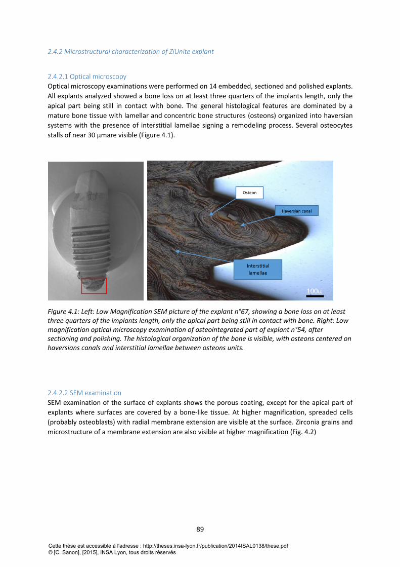
89
2.4.2 Microstructural characterization of ZiUnite explant
2.4.2.1 Optical microscopy
Optical microscopy examinations were performed on 14 embedded, sectioned and polished explants.
All explants analyzed showed a bone loss on at least three quarters of the implants length, only the
apical part being still in contact with bone. The general histological features are dominated by a
mature bone tissue with lamellar and concentric bone structures (osteons) organized into haversian
systems with the presence of interstitial lamellae signing a remodeling process. Several osteocytes
stalls of near 30 µmare visible (Figure 4.1).
Figure 4.1: Left: Low Magnification SEM picture of the explant n°67, showing a bone loss on at least three quarters of the implants length, only the apical part being still in contact with bone. Right: Low magnification optical microscopy examination of osteointegrated part of explant n°54, after sectioning and polishing. The histological organization of the bone is visible, with osteons centered on haversians canals and interstitial lamellae between osteons units.
2.4.2.2 SEM examination
SEM examination of the surface of explants shows the porous coating, except for the apical part of
explants where surfaces are covered by a bone-like tissue. At higher magnification, spreaded cells
(probably osteoblasts) with radial membrane extension are visible at the surface. Zirconia grains and
microstructure of a membrane extension are also visible at higher magnification (Fig. 4.2)
Haversian canal
Interstitial
lamellae
Osteon
100µ
Cette thèse est accessible à l'adresse : http://theses.insa-lyon.fr/publication/2014ISAL0138/these.pdf © [C. Sanon], [2015], INSA Lyon, tous droits réservés
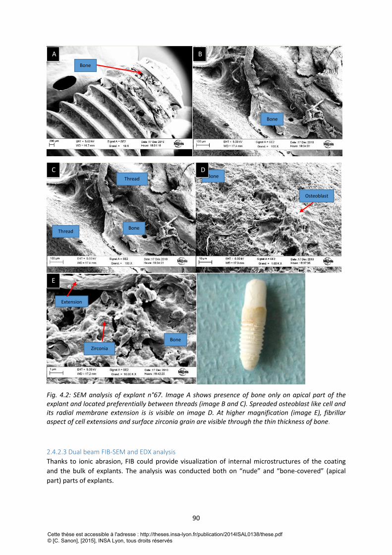
90
Fig. 4.2: SEM analysis of explant n°67. Image A shows presence of bone only on apical part of the explant and located preferentially between threads (image B and C). Spreaded osteoblast like cell and its radial membrane extension is is visible on image D. At higher magnification (image E), fibrillar aspect of cell extensions and surface zirconia grain are visible through the thin thickness of bone.
2.4.2.3 Dual beam FIB-SEM and EDX analysis
Thanks to ionic abrasion, FIB could provide visualization of internal microstructures of the coating
and the bulk of explants. The analysis was conducted both on “nude” and “bone-covered” (apical
part) parts of explants.
A B
C
E
Bone
Bone
Bone
Bone
Osteoblast
D
Extension
Zirconia
Bone
Thread
Thread
Cette thèse est accessible à l'adresse : http://theses.insa-lyon.fr/publication/2014ISAL0138/these.pdf © [C. Sanon], [2015], INSA Lyon, tous droits réservés
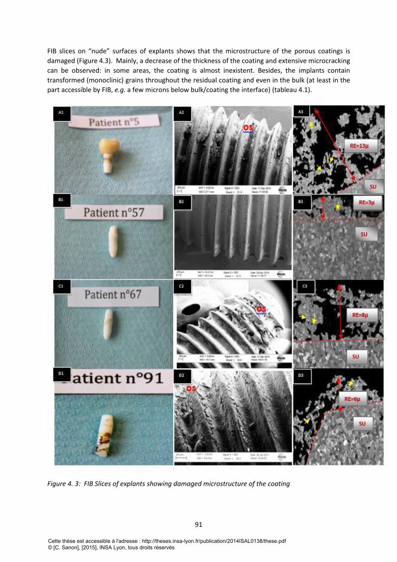
91
FIB slices on “nude” surfaces of explants shows that the microstructure of the porous coatings is
damaged (Figure 4.3). Mainly, a decrease of the thickness of the coating and extensive microcracking
can be observed: in some areas, the coating is almost inexistent. Besides, the implants contain
transformed (monoclinic) grains throughout the residual coating and even in the bulk (at least in the
part accessible by FIB, e.g. a few microns below bulk/coating the interface) (tableau 4.1).
Figure 4. 3: FIB Slices of explants showing damaged microstructure of the coating
Cette thèse est accessible à l'adresse : http://theses.insa-lyon.fr/publication/2014ISAL0138/these.pdf © [C. Sanon], [2015], INSA Lyon, tous droits réservés
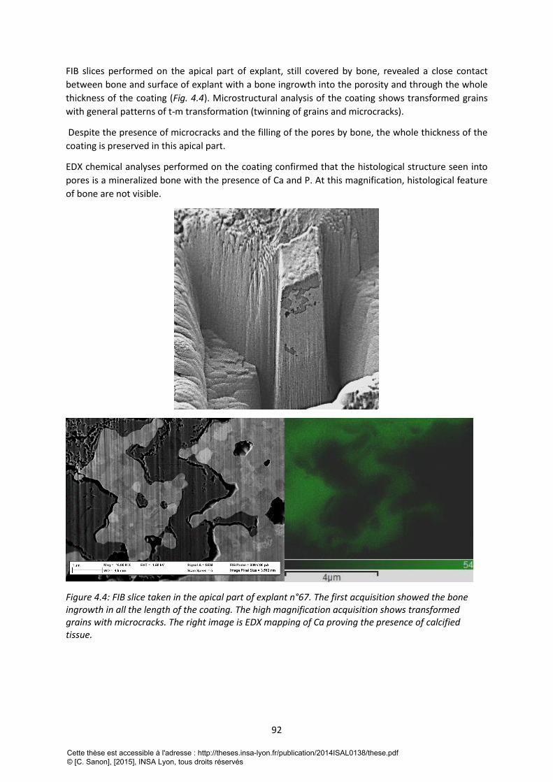
92
FIB slices performed on the apical part of explant, still covered by bone, revealed a close contact
between bone and surface of explant with a bone ingrowth into the porosity and through the whole
thickness of the coating (Fig. 4.4). Microstructural analysis of the coating shows transformed grains
with general patterns of t-m transformation (twinning of grains and microcracks).
Despite the presence of microcracks and the filling of the pores by bone, the whole thickness of the
coating is preserved in this apical part.
EDX chemical analyses performed on the coating confirmed that the histological structure seen into
pores is a mineralized bone with the presence of Ca and P. At this magnification, histological feature
of bone are not visible.
Figure 4.4: FIB slice taken in the apical part of explant n°67. The first acquisition showed the bone ingrowth in all the length of the coating. The high magnification acquisition shows transformed grains with microcracks. The right image is EDX mapping of Ca proving the presence of calcified tissue.
Cette thèse est accessible à l'adresse : http://theses.insa-lyon.fr/publication/2014ISAL0138/these.pdf © [C. Sanon], [2015], INSA Lyon, tous droits réservés
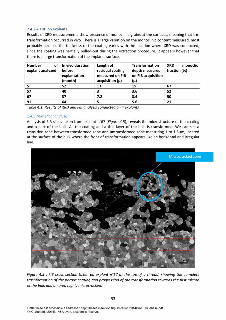
93
2.4.2.4 XRD on explants
Results of XRD measurements show presence of monoclinic grains at the surfaces, meaning that t-m
transformation occurred in vivo. There is a large variation on the monoclinic content measured, most
probably because the thickness of the coating varies with the location where XRD was conducted,
since the coating was partially pulled-out during the extraction procedure. It appears however that
there is a large transformation of the implants surface.
Number of explant analyzed
In vivo duration before explantation (month)
Length of residual coating measured on FIB acquisition (µ)
Transformation depth measured on FIB acquisition (µ)
XRD monoclic fraction (%)
5 52 13 15 67
57 40 3 3.6 52
67 37 7.2 8.4 50
91 64 5 5.6 21
Table 4.1: Results of XRD and FIB analysis conducted on 4 explants
2.4.3 Numerical analysis
Analysis of FIB slices taken from explant n°67 (Figure 4.5), reveals the microstructure of the coating and a part of the bulk. All the coating and a thin layer of the bulk is transformed. We can see a transition zone between transformed zone and untransformed zone measuring 1 to 1.5µm, located at the surface of the bulk where the front of transformation appears like an horizontal and irregular line.
Figure 4.5 : FIB cross section taken on explant n°67 at the top of a thread, showing the complete
trasnformation of the porous coating and progression of the transformation towards the first micron
of the bulk and an area highly microcracked.
1µ
Microcracked zone
Cette thèse est accessible à l'adresse : http://theses.insa-lyon.fr/publication/2014ISAL0138/these.pdf © [C. Sanon], [2015], INSA Lyon, tous droits réservés
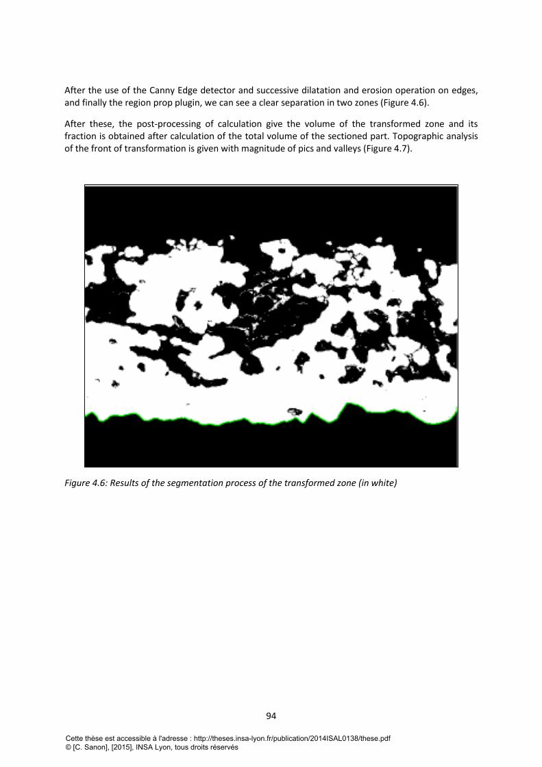
94
After the use of the Canny Edge detector and successive dilatation and erosion operation on edges, and finally the region prop plugin, we can see a clear separation in two zones (Figure 4.6).
After these, the post-processing of calculation give the volume of the transformed zone and its fraction is obtained after calculation of the total volume of the sectioned part. Topographic analysis of the front of transformation is given with magnitude of pics and valleys (Figure 4.7).
Figure 4.6: Results of the segmentation process of the transformed zone (in white)
Cette thèse est accessible à l'adresse : http://theses.insa-lyon.fr/publication/2014ISAL0138/these.pdf © [C. Sanon], [2015], INSA Lyon, tous droits réservés
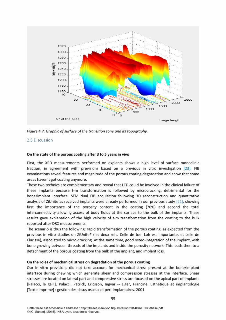
95
Figure 4.7: Graphic of surface of the transition zone and its topography.
2.5 Discussion
On the state of the porous coating after 3 to 5 years in vivo
First, the XRD measurements performed on explants shows a high level of surface monoclinic
fraction, in agreement with previsions based on a previous in vitro investigation [23]. FIB
examinations reveal features and magnitude of the porous coating degradation and show that some
areas haven’t got coating anymore.
These two technics are complementary and reveal that LTD could be involved in the clinical failure of
these implants because t-m transformation is followed by microcracking, detrimental for the
bone/implant interface. SEM dual FIB acquisition following 3D reconstruction and quantitative
analysis of ZiUnite as received implants were already performed in our previous study [21], showing
first the importance of the porosity content in the coating (76%) and second the total
interconnectivity allowing access of body fluids at the surface to the bulk of the implants. These
results gave explanation of the high velocity of t-m transformation from the coating to the bulk
reported after DRX measurements.
The scenario is thus the following: rapid transformation of the porous coating, as expected from the
previous in vitro studies on ZiUnite® (les deux refs. Celle de Joel Loh est importante, et celle de
Clarisse), associated to micro-cracking. At the same time, good osteo-integration of the implant, with
bone growing between threads of the implants and inside the porosity network. This leads then to a
detachment of the porous coating from the bulk of the implant, and implant loss.
On the roles of mechanical stress on degradation of the porous coating
Our in vitro previsions did not take account for mechanical stress present at the bone/implant
interface during chewing which generate shear and compression stresses at the interface. Shear
stresses are located on lateral part and compressive stress are focused on the apical part of implants
[Palacci, le gall,]. Palacci, Patrick, Ericsson, Ingvar -- Liger, Francine. Esthétique et implantologie
[Texte imprimé] : gestion des tissus osseux et péri-implantaires. 2001.
Cette thèse est accessible à l'adresse : http://theses.insa-lyon.fr/publication/2014ISAL0138/these.pdf © [C. Sanon], [2015], INSA Lyon, tous droits réservés
96
It is known that shear stresses can be detrimental for the bone/implant interface [24,25]. This may
be especially true in the case of porous coating and even more in the case of aged coating which is
brittler with microcracks
However, compressive stresses could be beneficial for the bone/implant interface, strengthening
anchorage of bone into the coating and closing microcracks of the coating.
All explants analyzed here present an apical part still covered by bone, although the coating at the
apical part is completely transformed; this is compatible to an apical area of implants subjected to
very low shear stresses and/or to compressive stresses, as it is generally accepted in literature [26-
29].
On the contrary, only few tissue was found on the lateral parts of the implants, and at this location
the coating is highly damaged (microcracked and even pulled-out), which is compatible with the high
shear stresses expected from the literature [26-29]
As we noted, LTD could lead to a microcracking of the coating, leading to the loss of bone/implant
integration and subparticles created during the microcracking of the porous coating could lead to an
inflammation of peri-implant tissue that’s to say to a peri-implantitis which finally conducted to bone
resorption.
With this, an additional bacterial colonization of the gap between the bone and the implant is
possible.
On the innovating numerical technology for 3Y-TZP zirconia materials
So far, no clinical study was conducted on zirconia dental implants with an emphasis on LTD although
several cases of failures related to t-m transformation were reported for zirconia heads in orthopedic
fields. The microstructural investigation of the surface and sub-surface damage by XRD and FIB
allowed us to assess the degree of transformation, micro-cracking and delamination of the porous
ZiUnite® coating after some years in vivo, which could explain the high level of implant failures
clinically.
As we already said, the numerical approach is powerful for deeper characterization of zirconia but it
could be enhanced if untransformed grains in transformed zone could be detected and quantified
and more if we could detect the transformed fraction in a grain in transition zone, where grains are
not totally transformed or in the case of toughening transformation induce by mechanical stress
which lead to partially transformed grains [30].
2.6 Conclusion This experiment shows first, that we could learn a lot with deeper study of explants, secondly, that
interdisciplinary methods offers an unlimited way to expand our knowledge on material
characterization.
We have highlighted in this study, the existence and significance of in vivo LTD on zirconia materials,
even after a short in vivo duration. LTD could be implicated in the loss of osteointégration by
delamination of the coating and or release of zirconia particles causing inflammatory reaction and
peri-implant bone resorption. It should be not accepted to not take into account for the possibility of
this failure mode in clinical studies relating on zirconia implants.
Cette thèse est accessible à l'adresse : http://theses.insa-lyon.fr/publication/2014ISAL0138/these.pdf © [C. Sanon], [2015], INSA Lyon, tous droits réservés
97
2.7 Références bibliographiques de la 4ème partie [1] Branemark P I. Osseointegration and its experimental background. The Journal of prosthetic
dentistry,1983;50:(3), 399-410.
[2]Babbush CA, Hahn JA, Krauser JT, Rosenlicht JL. Dental implants: the art and science.Maryland
Heights: Saunders/Elsevier ; 2011.
[3]Karoussis I K, Salvi GE, Heitz-Mayfield LJA, Brägger U, Hämmerle CHF, Lang NP. Long-term implant
prognosis in patients with and without a history of chronic periodontitis: a 10-year prospective
cohort study of the ITI® Dental Implant System. Clin Oral Implants Res 2003;14 (3): 329-39.
[4] Dunn DB. The use of a zirconia custom implant-supported fixed partial denture prosthesis to treat
implant failure in the anterior maxilla: a clinical report. Journal of Prosthetic Dentistry 2008;100:415–
21
[5]Vamanu, C. I., Høl, P. J., Allouni, Z. E., Elsayed, S., & Gjerdet, N. R. (2008). Formation of potential
titanium antigens based on protein binding to titanium dioxide nanoparticles. International journal of
nanomedicine, 3(1), 69.
[6] Sicilia, A., Cuesta, S., Coma, G., Arregui, I., Guisasola, C., Ruiz, E., & Maestro, A. (2008). Titanium
allergy in dental implant patients: a clinical study on 1500 consecutive patients. Clinical oral implants
research, 19(8), 823-835.
[7] Oliva, J., Oliva, X., & Oliva, J. D. (2009). Five-year success rate of 831 consecutively placed Zirconia
dental implants in humans: a comparison of three different rough surfaces. The International journal
of oral & maxillofacial implants, 25(2), 336-344.
[8] Manicone, P. F., Rossi Iommetti, P., & Raffaelli, L. (2007). An overview of zirconia ceramics: basic
properties and clinical applications. Journal of dentistry, 35(11), 819-826.
[9] Gahlert M, Gudehus T, Eichhorn S, Steinhauser E, Kniha H, Erhardt W. Biomechanical and
histomorphometric comparison between zirconia implants with varying surface textures and a
titanium implant in the maxilla of miniature pigs. Clin Oral Implants Res 2007 ; 18 (5): 662-8.
[10] Scarano A, Piattelli M, Caputi S, Favero GA, Piattelli A. Bacterial adhesion on commercially pure
titanium and zirconium oxide disks: an in vivo human study. J Periodontol 2004 ; 75 (2) : 292-6.
[11] Chevalier J, Gremillard L, Virkar A, Clarke DR. The tetragonal-monoclinic transformation in
zirconia: Lessons learned and future trends. J Am Ceram Soc,2009;92:1901-1920.
[12] Chevalier J. What future for zirconia as a biomaterial? Biomater, 2006;27:535-543.
[13] Sennerby L, Dasmah A, Larsson B, Iverhed M. Bone tissue responses to surface-modified zirconia
implants: a histomorphometric and removal torque study in the rabbit. Clinical Implant Dentistry and
Related Research 2005;7:13–20, 2005.
[14] Depprich R, Zipprich H, Ommerborn M, Naujoks C, Wiesmann HP, Kiattavorncharoen S, et al.,
Meyer U, Handschel J. Osseointegration of zirconia implants compared with titanium: an in vivo
study. Head and Face Medicine 2008;4, art. 30.
[15] Yamashita D, Machigashira M, Miyamoto M, Takeuchi H, Noguchi K, Izumi Y, et al. Effect of
surface roughness on initial responses of osteoblast-like cells on two types of zirconia. Dental
Materials Journal 2009;28:461–70.
Cette thèse est accessible à l'adresse : http://theses.insa-lyon.fr/publication/2014ISAL0138/these.pdf © [C. Sanon], [2015], INSA Lyon, tous droits réservés
98
[16] Andreiotelli M, Kohal RJ. Fracture strength of zirconia implants after artificial aging. Clin Implant
Dent Relat Res 2009 ; 11 (2) : 158-66.
[17] Sennerby L, Dasmah A, Larsson B, Iverhed M. Bone tissue responses to surface modified zirconia
implants: a histomorphometric and removal torque study in the rabbit. Clinical Implants Dentistry
and Related Research 2005 ; 7 (Suppl 1) : S13-20.
[18] Rocchietta I, Fontana F, Addis A, Schüpbach P, Simion M. Surface-modified zirconia implants:
tissue response in rabbits. Clin Oral Implants Res 2009 ; 20 (8) : 844-50.
[19] Kohal RJ, Knauf M, Larsson B, Sahlin H, Butz F. One-piece zirconia oral implants: 1 year results
from a prospective cohort study. 1. Single tooth replacement. J Clinical Periodontol 2012 ; 39 (6) :
590-7.
[20] Chevalier J, Loh J, Gremillard L, Meille S, Adolfson E. Low-temperature degradation in zirconia
with a porous surface. Acta Biomater 2011 ; 7 (7) : 2986-93.
[21] Sanon C, Chevalier J, Douillard T, Kohal RJ, Coelho PG, Hjerppe J, Silva NRFA. Low temperature
degradation and reliability of one-piece ceramic oral implants with a porous surface. Dent Mater
2013; 29 (4) : 389-97.
[22] Kohal RJ1, Patzelt SB, Butz F, Sahlin H.: One-piece zirconia oral implants: one-year results from a
prospective case series. 2. Three-unit fixed dental prosthesis (FDP) reconstruction.J Clin Periodontol.
2013 May;40(5):553-62. doi: 10.1111/jcpe.12093. Epub 2013 Mar 18.).
[23] Sanon, C., Chevalier, J., Douillard, T., Cattani-Lorente, M., Scherrer, S. S., & Gremillard, L. (2014).
A new testing protocol for zirconia dental implants. Dental Materials. Article in press.
[24] Palacci, Patrick, Ericsson, Ingvar -- Liger, Francine. Esthétique et implantologie [Texte imprimé] :
gestion des tissus osseux et péri-implantaires. 2001.
[25] Le Gall MG, Lauret JF. La fonction occlusale: implications cliniques. Paris: Editions CdP ; 1998.
[26] G. Grégoire et C. Séverin. Elaboration, caractérisation et biointégration. Journal de Biomatériaux
Dentaires, vol.9, 1994
[27] Gross M. D., & Nissan, J. (2001). Stress distribution around maxillary implants in anatomic
photoelastic models of varying geometry. Part II. The Journal of prosthetic dentistry, 85(5), 450-454.
[28] Sevimay, M., Turhan, F., Kiliçarslan, M. A., & Eskitascioglu, G. (2005). Three-dimensional finite
element analysis of the effect of different bone quality on stress distribution in an implant-supported
crown. The Journal of prosthetic dentistry, 93(3), 227-234.
[29] Koca, O. L., Eskitascioglu, G., & Usumez, A. (2005). Three-dimensional finite-element analysis of
functional stresses in different bone locations produced by implants placed in the maxillary posterior
region of the sinus floor. The Journal of prosthetic dentistry, 93(1), 38-44.
[30] Muñoz-Tabares, J. A., Jiménez-Piqué, E., Reyes-Gasga, J., & Anglada, M. (2012). Microstructural
changes in 3Y-TZP induced by scratching and indentation. Journal of the European Ceramic Society,
32(15), 3919-3927.
Cette thèse est accessible à l'adresse : http://theses.insa-lyon.fr/publication/2014ISAL0138/these.pdf © [C. Sanon], [2015], INSA Lyon, tous droits réservés
99
CINQUIEME PARTIE : CONCLUSION
Dans la première partie, la synthèse bibliographique nous montre, au préalable, que les
connaissances accumulées dans chacune des disciplines abordées sont à la fois étendue et
spécifique, et cette tendance à la spécialisation fractionne finalement les savoirs entrainant un
manque de communication entre les différents domaines. Prenons pour exemple, le phénomène de
vieillissement de la zircone 3Y-TZP qui a été découvert au début des années 1980 et qui est encore
sous-estimé dans le domaine de l’implantologie orale, alors que des implants en zircone 3Y-TZP sont
commercialisés depuis le début des années 2000.
Il était donc primordial de valider et d’appliquer les connaissances acquises dans le domaine des
sciences des matériaux sur la zircone 3Y-TZP et de l’histoire de celle-ci en orthopédie pour son
application en implantologie oral. C’est l’objectif de notre première publication : “Low temperature
degradation and reliability of one-piece ceramic oral implants with a porous surface” où nous avons
mis en évidence l’influence du procédé d’élaboration sur le comportement mécanique et la stabilité
microstructurale des implants et en particulier, l’influence de la taille des grains sur la cinétique de
vieillissement, puis l’effet du vieillissement sur les propriétés mécaniques. Nous avons constaté que
chaque procédé d’élaboration aboutit à une microstructure particulière, qui par la suite, influence la
durabilité du produit fini. Concernant l’implant étudié dans cette publication, nous avons observé
entre autres, une microfissuration de la surface au cours du vieillissement, ce qui, in vivo, pourrait
entrainer une délamination de la surface de l’implant et une libération de particules de revêtement,
défavorables au maintien de l’ostéointégration.
Dans notre deuxième publication : “A new testing protocol for zirconia dental implants”, nous
proposons un protocole d’évaluation prenant réellement en compte les spécificités du produit fini. Il
permet dans un premier temps, d’évaluer l’effet de l’état de surface et de la microstructure sur la
résistance mécanique d’implants neufs, puis de suivre leurs cinétiques de vieillissement tout en
analysant l’évolution de la microstructure et son influence sur la résistance mécanique au cours du
vieillissement, tout cela permettant in fine, de prédire la durabilité d’un type d’implant. Les résultats
de notre étude montrent que les surfaces alvéolaires et poreuses, développées dans l’optique
d’améliorer l’ostéointégration, peuvent être délétères pour la durabilité de l’implant, dans un cas
affectant la résistance mécanique par la présence de défauts critiques, et dans l’autre cas accélérant
le phénomène de vieillissement du fait de l’importance de la porosité et de son interconnexion. De
ce fait, aucune généralisation ne peut être faite, chaque type d’implant doit faire l’objet d’une étude
approfondie intégrant l’analyse de la microstructure et l’évaluation de la durabilité.
Les cinétiques de vieillissement ont été réalisées par des mesures périodique en DRX, les résultats
sont globalement cohérents avec les estimations retrouvées dans la littérature, mais ce suivi pourrait
être amélioré par l’utilisation de la spectrométrie Raman, du fait de la géométrie complexe des
implants dentaires. Par ailleurs, l’utilisation de la technologie innovante du FIB permet d’approfondir
la caractérisation microstructurale des implants grâce à la possibilité de traitements d’image donnant
accès à la quantification de la microstructure et de son évolution. Nous avons pu ainsi quantifier des
paramètres tels que la porosité, l’interconnexion de cette porosité et les différentes phases en
présence, et cela a grandement apporté à la compréhension du comportement microstructural et
mécanique des implants étudiés.
En exploitant cette possibilité de traitement des images acquises par le FIB, nous avons développé un
programme informatique (sur le logiciel Matlab®) permettant la détection et la quantification du
vieillissement pour un volume donné. Cette détection de la zone vieillie ou transformée est fondée
Cette thèse est accessible à l'adresse : http://theses.insa-lyon.fr/publication/2014ISAL0138/these.pdf © [C. Sanon], [2015], INSA Lyon, tous droits réservés
100
sur les modifications microstructurales engendrées lors du vieillissement et qui sont bien visibles sur
les acquisitions du FIB. Les résultats obtenus en termes de quantification pourraient être affinés, en
développant d’avantage la méthode de segmentation de la zone vieillie.
Alors que l’ensemble de notre travail de thèse concernait jusqu’à présent l’étude d’implants en
zircone 3Y-TZP vieillis artificiellement, nous proposons dans la quatrième partie, l’analyse d’explants
en zircone 3Y-TZP issus d’une étude clinique. Ils ont été extraits de l’alvéole osseuse après 3 à 5 ans
de mastication à la suite du constat clinique de la mobilité des implants dans leur alvéole,
témoignant de la perte d’ostéointégration de l’implant. Notre objectif était d’étudier l’implication du
phénomène de vieillissement sur cette perte d’ostéointégration. Dans un premier temps, nous avons
montré après quantification et visualisation, que ces explants avaient été sujet au vieillissement in
vivo et présentaient une surface transformée, microfissurée et délaminée. Le vieillissement
pourraient donc être impliqué dans cette perte d’ostéointégration, soit du fait de la délamination
(c’est-à-dire de la désintégration de la surface, conduisant à la perte de contact avec l’os), soit du fait
de la libération de particules de zircone (entrainant une réaction inflammatoire, à l’origine d’une
résorption de l’os péri-implantaire).
Nous avons pu mettre en évidence les relations ou réactions existant entre l’os et l’implant à trois
niveaux :
- d’abord à un niveau biochimique par la transformation de phase de la zircone au contact
des fluides biologiques contenus dans l’os,
- puis à un niveau histologique, mettant en évidence la capacité de biocompatibilité et
d’ostéointégration de la zircone, avec la formation d’un tissu osseux mature autour de l’implant
- enfin, à un niveau biomécanique avec l’action des différentes composantes des forces
masticatoires s’exerçant à la surface de l’implant et conduisant à une perte osseuse peri-implantaire
caractéristique.
Nous avons pu également appliquer le logiciel informatique de traitement d’image développé afin
de mettre en lumière et d’expliciter l’existence de ce phénomène de vieillissement in vivo, qui n’est
toujours pas pris en compte dans les études cliniques.
Ce travail de thèse met en outre, en lumière, cette nécessité de créer des liens, des interfaces entre
les différentes disciplines impliquées dans cette application, dans le but de sensibiliser les acteurs de
ce marcher aux problématiques rencontrées et d’optimiser de ce dispositif médical, à la lumière des
connaissances actuelles. Sans l’apport de praticiens, d’experts en science des matériaux céramiques
et en microscopie et de spécialistes du traitement de l’image, ce travail n’aurait pas pu être aussi
complet.
Cette thèse est accessible à l'adresse : http://theses.insa-lyon.fr/publication/2014ISAL0138/these.pdf © [C. Sanon], [2015], INSA Lyon, tous droits réservés
101
ANNEXES
1.Table des figures Figure 1.1 L’implant CBS (Crystalline Bone Screw).
Figure 1.2 : Implants Frialit 1 (Friadent, Allemagne).
Figure 1.3 : Implant Z-LOOK (Z-Systems, Allemagne).
Figure 1.4: CIM® implant (Straumann®, Suisse)
Figure 1.5: Schéma des structures cristallographiques quadratique (ou tetragonal) et monoclinique de
la zircone, montrant la composante de cisaillement lors du passage de la forme quadratique vers la
forme monoclinique.
Figure1.6 : Mécanisme de renforcement de la zircone 3Y-TZP par transformation de phase.
Figure 1.7: Mécanisme de vieillissement de la zircone 3Y-TZP
Figure 1.8 : Contraintes calculées par la méthode des éléments finis dans un implant en zircone, dans
le cadre d’un essai suivant les conditions de chargement de la norme ISO 14801. Crédit : Pierre-Yves
Prodhomme, AKEO+.
Figure 1.9 : Evolution de la contrainte à la rupture d’une céramique présentant une ténacité de 6
MPa√m, en fonction du type et de la taille de défauts pouvant être rencontrés.
Figure 1.10 : Aspect inesthétique du sourire causé avec un implant en titane.
Figure 1.11 : Solutions de protection utilisée pendant la phase de cicatrisation. Prothèse amovible
évidée en regard de l’implant à droite et gouttière de protection à gauche.
Figure 2.1: (a) Focused Ion Beam 3D reconstruction of an implant surface (top of a thread) showing
the polycrystalline nature of the material (orientation contrast) and the porosity of the surface
coating. Parameters of the volume: Volume: 18 x 11 x 4 μm³, Voxel size: 10 x 10 x 10 nm³. (b) FIB-Slice
cross-section. Note the different grain size in the porous layer (sintered once) and the bulk (sintered
twice). Pores appear in black
Figure 2.2: Image analysis obtained by contrast segmentation of a FIB reconstruction. Interconnected
porosity (in the porous coating) is in red, closed pores (in the bulk, underneath the porous coating) in
blue, and alumina grains in green.
Figure 2.3: Evolution of XRD monoclinic fraction versus aging duration at 134°C in autoclave (●),
compared to previous work (Chevalier et al. [18]) on a dense 3Y-TZP (○). Inserts represent the depth of
the monoclinic layer as observed by FIB.
Figure 2.4: FIB cross-sections taken from the surface of an implant aged for 20 hours (a) and 100
hours (b). The three inserts of Figure 5b show the different contrasts observed in the untransformed
areas and in the transformed zone (twining of the grains).
Figure 2.5: 3D FIB reconstruction of the implant aged for 20 hours (a) and 100 hours (b), after an
image segmentation highlighting micro-cracks (in green).
Cette thèse est accessible à l'adresse : http://theses.insa-lyon.fr/publication/2014ISAL0138/these.pdf © [C. Sanon], [2015], INSA Lyon, tous droits réservés
102
Figure 2.6: (a) Risk of failure (Unreliability) as a function of number of cycles for 1000 N load (Use
stress 90% CB), for non-aged (black circles) and aged (blue circles) implants. (b) Survival probability
versus load for non-aged (black circles) and aged (blue circles) implants.
Figure 3.1: SEM pictures of the three types of implants and their surface features.
Figure 3.2: FIB /SEM pictures of the surface of as-received implants.
Figure 3.3: (a) FIB/SEM picture of a ZiUnite implant (as-received) at higher magnification, showing
transformation of grains around pores even before accelerated aging tests. (b) 3D reconstruction of
the surface coating the after relevant segmentation, to highlight the porosity features of the material
(22μm x 4μm x 12.5μm). Interconnected porosity is in blue whereas isolated pores are in green.
Figure 3.4: (a) Comparison of aging kinetics measured directly at the surface of a ZiUnite implant and
on a sectioned and polished implant (as recommended by ISO 13356). (b) Aging kinetics of ZiUnite,
Axis-Rough and Axis-Alveolar implants, all measured at their surface.
Figure 3.5: FIB/SEM pictures of the surface of the implants after 5 hours of aging at 134°C. (a) and (b)
for ZiUnite showing a entire transformation of the porous coating, (c) and (d) for AXIS „Rough‟ and
“Alveolar‟ showing only limited transformation. Dashed lines represent the limit of the
transformation zone.
Figure 3.6: Fractography of the two types of AXIS experimental implants, after load to failure tests.
Figure 3.7 : Acquisition du FIB montrant la microstructure de l’implant. Les grains transformés se
distinguent des grains non transformés (cercle bleu) par leur aspect strié (cercle rouge). Certains
grains sont partiellement transformés (cercle orange). Le front de transformation est horizontal mais
irrégulier, il est situé dans l’intervalle des deux lignes : la zone de transition.
Figure 3.8 : Image traité par le module de détection de contours « Canny edge detector ». Les deux
zones se distinguent aisément par la différence de densité de contour créant un contraste.
Figure 3.9 : Résultats obtenues après plusieurs opérations d’érosion/dilatation.
Figure 3.10: Après utilisation du module de globalisation des zones « Region-prop », la délimitation
est claire. La zone transformée (blanche) va être extraite et quantifiée.
Figure 3.11 : Tracé du front de transformation sur l’image originale rendue possible après les
opérations successives.
Figure 3.12 : Ajustement du nombre d’érosion et de dilatation nécessaires pour la quantification du
volume total.
Figure 3.13. : L’implant Zir Roc Sablé (Paris Implant). Photographie générale, micrographie des filets
usinés puis de la surface (MEB).
Figure 3.14 : Image obtenue par usinage ionique, au FIB (en haut)), puis reconstruction 3D (en bas) et
quantification des fissures, des grains d’alumine et des pores pour un volume de 19.9 µm x13.78
µmx1.52 µm.
Figure 3.15 : Analyse du niveau de l’interface et de sa topographie. L’amplitude maximale des pics et
des vallées est évaluée de 0 à 1000nm
Figure 3.16 : Courbes obtenues après suivi de l’évolution de la transformation de différents types
d’implants analysés. La courbe bleue correspond à celle des implants ZirRoc.
Cette thèse est accessible à l'adresse : http://theses.insa-lyon.fr/publication/2014ISAL0138/these.pdf © [C. Sanon], [2015], INSA Lyon, tous droits réservés
103
Figure 4.1: Left: Low Magnification SEM picture of the explant n°67, showing a bone loss on at least three quarters of the implants length, only the apical part being still in contact with bone. Right: Low magnification optical microscopy examination of osteointegrated part of explant n°54, after sectioning and polishing. The histological organization of the bone is visible, with osteons centered on haversians canals and interstitial lamellae between osteons units.
Fig. 4.2: SEM analysis of explant n°67. Image A shows presence of bone only on apical part of the explant and located preferentially between threads (image B and C). Spreaded osteoblast like cell and its radial membrane extension is is visible on image D. At higher magnification (image E), fibrillar aspect of cell extensions and surface zirconia grain are visible through the thin thickness of bone.
Figure 4. 3: FIB Slices of explants showing damaged microstructure of the coating
Figure 4.4: FIB slice taken in the apical part of explant n°67. The first acquisition showed the bone ingrowth in all the length of the coating. The high magnification acquisition shows transformed grains with microcracks. The right image is EDX mapping of Ca proving the presence of calcified tissue.
Figure 4.5 : FIB cross section taken on explant n°67 at the top of a thread, showing the complete
trasnformation of the porous coating and progression of the transformation towards the first micron
of the bulk and an area highly microcracked.
Figure 4.6: Results of the segmentation process of the transformed zone (in white)
Figure 4.7: Graphic of surface of the transition zone and its topography.
2. Table des tableaux Tableau 1.1 : Différence de paramètres entre la maille monoclinique et quadratique, expliquant
l’apparition des contraintes dans la zircone massive lors de la transformation de phase.
Tableau 1.2: Valeurs des modules élastiques traduisant le degré de rigidité de différents matériaux et
tissus.
Tableau 1.3 : Synthèses des études effectuées sur la capacité d’ostéointégration de la zircone 3Y-TZP.
Tableau 1.4: Implants dentaires en zircone 3Y-TZP disponibles actuellement.
Tableau 1.5: Systèmes implantaires proposant des implants dentaires 3Y-TZP en 2 pièces.
Tableau 1.6 : Valeurs des modules d’élasticité traduisant le degré de rigidité de différents matériaux
et tissus.
Table 2.1: Reliability for a mission of 100,000 cycles at 700 and 1000 N Load. Ceramic implant groups
were defined as aged and non-aged.
Table 3.1: Results of the load to failure (average value and standard deviation) of the AXIS
experimental implants, in the as-received state or after 5 hours or 100 hours of accelerated aging at
134°C
Table 4.1: Results of XRD and FIB analysis conducted on 4 explants
Cette thèse est accessible à l'adresse : http://theses.insa-lyon.fr/publication/2014ISAL0138/these.pdf © [C. Sanon], [2015], INSA Lyon, tous droits réservés
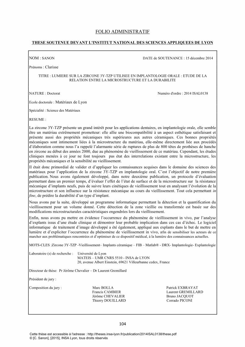
104
FOLIO ADMINISTRATIF
THESE SOUTENUE DEVANT L'INSTITUT NATIONAL DES SCIENCES APPLIQUEES DE LYON
NOM : SANON DATE de SOUTENANCE : 15 décembre 2014
Prénoms : Clarisse
TITRE : LUMIERE SUR LA ZIRCONE 3Y-TZP UTILISEE EN IMPLANTOLOGIE ORALE : ETUDE DE LA
RELATION ENTRE LA MICROSTRUCTURE ET LA DURABILITE
NATURE : Doctorat Numéro d'ordre : 2014 ISAL0138
Ecole doctorale : Matériaux de Lyon
Spécialité : Science des Matériaux
RESUME :
La zircone 3Y-TZP présente un grand intérêt pour les applications dentaires, en implantologie orale, elle semble
être un matériau extrêmement prometteur: elle allie une biocompatibilité à un aspect esthétique satisfaisant et
présente aussi des propriétés mécaniques très supérieures aux autres céramiques. Ces bonnes propriétés
mécaniques sont intimement liées à la microstructure du matériau, elle-même directement liée aux procédés
d’élaboration comme nous l’a rappelé l’alarmante série de ruptures de plus de 800 têtes de prothèses de hanche
en zircone au début des années 2000, due au phénomène de vieillissement de ce matériau. Cependant, les études
cliniques menées à ce jour ne font toujours pas état des interrelations existant entre la microstructure, les
propriétés mécaniques et la sensibilité au vieillissement.
Il était donc primordial de valider et d’appliquer les connaissances acquises dans le domaine des sciences des
matériaux pour l’application de la zircone 3Y-TZP en implantologie oral. C’est l’objectif de notre première
publication. Nous avons également développé, dans notre deuxième publication, un protocole d’évaluation
permettant dans un premier temps, d’évaluer l’effet de l’état de surface et de la microstructure sur la résistance
mécanique d’implants neufs, puis de suivre leurs cinétiques de vieillissement tout en analysant l’évolution de la
microstructure et son influence sur la résistance mécanique au cours du vieillissement. Tout cela permettant in
fine, de prédire la durabilité d’un type d’implant.
Nous avons par la suite, développé un programme informatique permettant la détection et la quantification du
vieillissement pour un volume donné. Cette détection de la zone vieillie ou transformée est basée sur des
modifications microstructurales caractéristiques engendrées lors du vieillissement.
Enfin, nous avons pu mettre en évidence l’occurrence du phénomène de vieillissement in vivo, par l’analyse
d’explants issus d’une étude clinique et démontrer leur probable implication dans ces cas d’échec. Le logiciel
informatique de traitement d’image développé a été également, appliqué aux explants dans le but de mettre en
lumière et d’expliciter l’occurrence du phénomène de vieillissement in vivo, afin de sensibiliser les acteurs de ce
marcher aux problématiques rencontrées et d’optimiser de ce dispositif médical, à la lumière des connaissances actuelles.
MOTS-CLES :Zircone 3Y-TZP -Vieillissement– Implants céramique – FIB – Matlab® - DRX- Implantologie- Explantologie
Laboratoire (s) de recherche : Université de Lyon
MATEIS – UMR CNRS 5510 - INSA de LYON
20, avenue Albert Einstein, 69621 Villeurbanne cedex, France
Directeur de thèse: Pr Jérôme Chevalier – Dr Laurent Gremillard
Président de jury :
Composition du jury : Marc BOLLA Patrick EXBRAYAT
Francis CAMBIER Laurent GREMILLARD
Jérôme CHEVALIER Bruno JACQUOT
Thierry DOUILLARD Corrado PICONI
Cette thèse est accessible à l'adresse : http://theses.insa-lyon.fr/publication/2014ISAL0138/these.pdf © [C. Sanon], [2015], INSA Lyon, tous droits réservés