Embed Size (px)
Citation preview
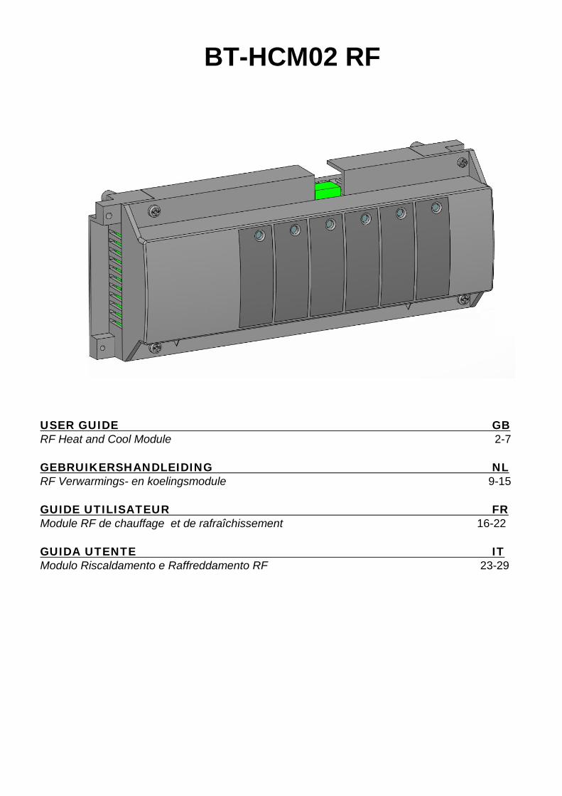
USER GUIDE GB RF Heat and Cool Module 2-7 GEBRUIKERSHANDLEIDING NL RF Verwarmings- en koelingsmodule 9-15 GUIDE UTILISATEUR FR Module RF de chauffage et de rafraîchissement 16-22 GUIDA UTENTE IT Modulo Riscaldamento e Raffreddamento RF 23-29
BT-HCM02 RF
2
1. USER GUIDE Heat & cool module BT-HCM02-RF is specially designed to control your Under Floor Heating & Cooling system. It is linked to your installation in RF (868MHz) via the BT-M6Z02 RF. BT-HCM02-RF can get Heat/Cool signal from different sources: - input free contact from Heat Pump output - input free contact for a manual switch - a NTC sensor to measure the water temperature inlet - from the BT-CT02-RF (BT-HCM02-RF configured in slave mode) BT-HCM02-RF has also some outputs for: - global pump of the system - Dehumidifier outputs in case of humidity default detected (in association with BT-D(P)02-RF RH thermostats) - Heat and Cool outputs to switch installation in Heating / Cooling
2. TECHNICAL CHARACTERISTICS
BT-HCM02 RF Operating Temperature 0°C to 50°C Supply Voltage 230VAC +- 10% 50Hz
Outputs: Heating and cooling Humidity drier Pump
2 x Relay => 5A / 250VAC (Free contact) 1 x Relay => 5A / 250VAC (Free contact) 1 x Relay => 5A / 230 VAC ( L, N)
Input: HC
HC input could be connected to • a free contact for a manual switch or Heat Pump output • a CTN 10K to measure the water temperature
Radio Frequency
868,3 MHz <10mW. Range of approximately 180 meters in open space. Range of approximately 50 meters in residential environment.
CE Directives Your product has been designed in conformity with the European Directives.
R&TTE 1999/5/EC LVD 2006/95/EC
EMC 2004/108/EC RoHS 2011/65/EU
Protection IP 30 Combination Only with BT-M6Z02-RF
3
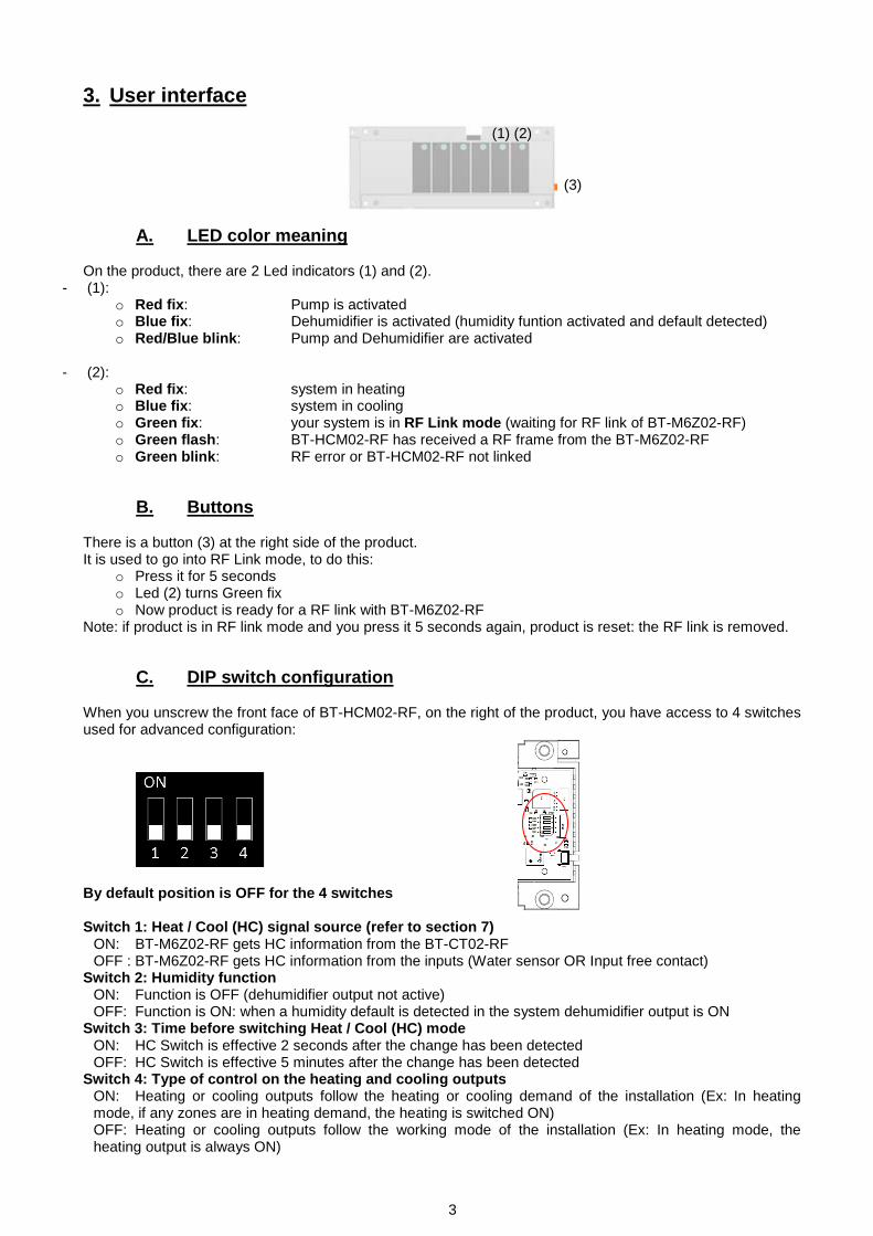
3. User interface
A. LED color meaning On the product, there are 2 Led indicators (1) and (2).
- (1): o Red fix: Pump is activated o Blue fix: Dehumidifier is activated (humidity funtion activated and default detected) o Red/Blue blink: Pump and Dehumidifier are activated
- (2):
o Red fix: system in heating o Blue fix: system in cooling o Green fix: your system is in RF Link mode (waiting for RF link of BT-M6Z02-RF) o Green flash: BT-HCM02-RF has received a RF frame from the BT-M6Z02-RF o Green blink: RF error or BT-HCM02-RF not linked
B. Buttons There is a button (3) at the right side of the product. It is used to go into RF Link mode, to do this:
o Press it for 5 seconds o Led (2) turns Green fix o Now product is ready for a RF link with BT-M6Z02-RF
Note: if product is in RF link mode and you press it 5 seconds again, product is reset: the RF link is removed.
C. DIP switch configuration When you unscrew the front face of BT-HCM02-RF, on the right of the product, you have access to 4 switches used for advanced configuration:
By default position is OFF for the 4 switches Switch 1: Heat / Cool (HC) signal source (refer to section 7)
ON: BT-M6Z02-RF gets HC information from the BT-CT02-RF OFF : BT-M6Z02-RF gets HC information from the inputs (Water sensor OR Input free contact)
Switch 2: Humidity function ON: Function is OFF (dehumidifier output not active) OFF: Function is ON: when a humidity default is detected in the system dehumidifier output is ON
Switch 3: Time before switching Heat / Cool (HC) mode ON: HC Switch is effective 2 seconds after the change has been detected OFF: HC Switch is effective 5 minutes after the change has been detected
Switch 4: Type of control on the heating and cooling outputs ON: Heating or cooling outputs follow the heating or cooling demand of the installation (Ex: In heating mode, if any zones are in heating demand, the heating is switched ON) OFF: Heating or cooling outputs follow the working mode of the installation (Ex: In heating mode, the heating output is always ON)
(1) (2)
(3)
4
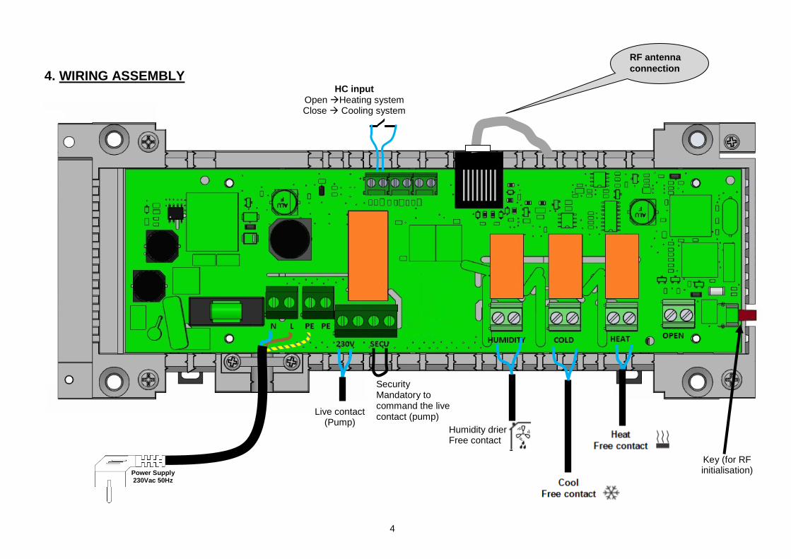
4. WIRING ASSEMBLY
RF antenna connection
HC input Open Heating system Close Cooling system
Humidity drier Free contact
Live contact (Pump)
Key (for RF initialisation) Power Supply
230Vac 50Hz
Security Mandatory to command the live contact (pump)
5
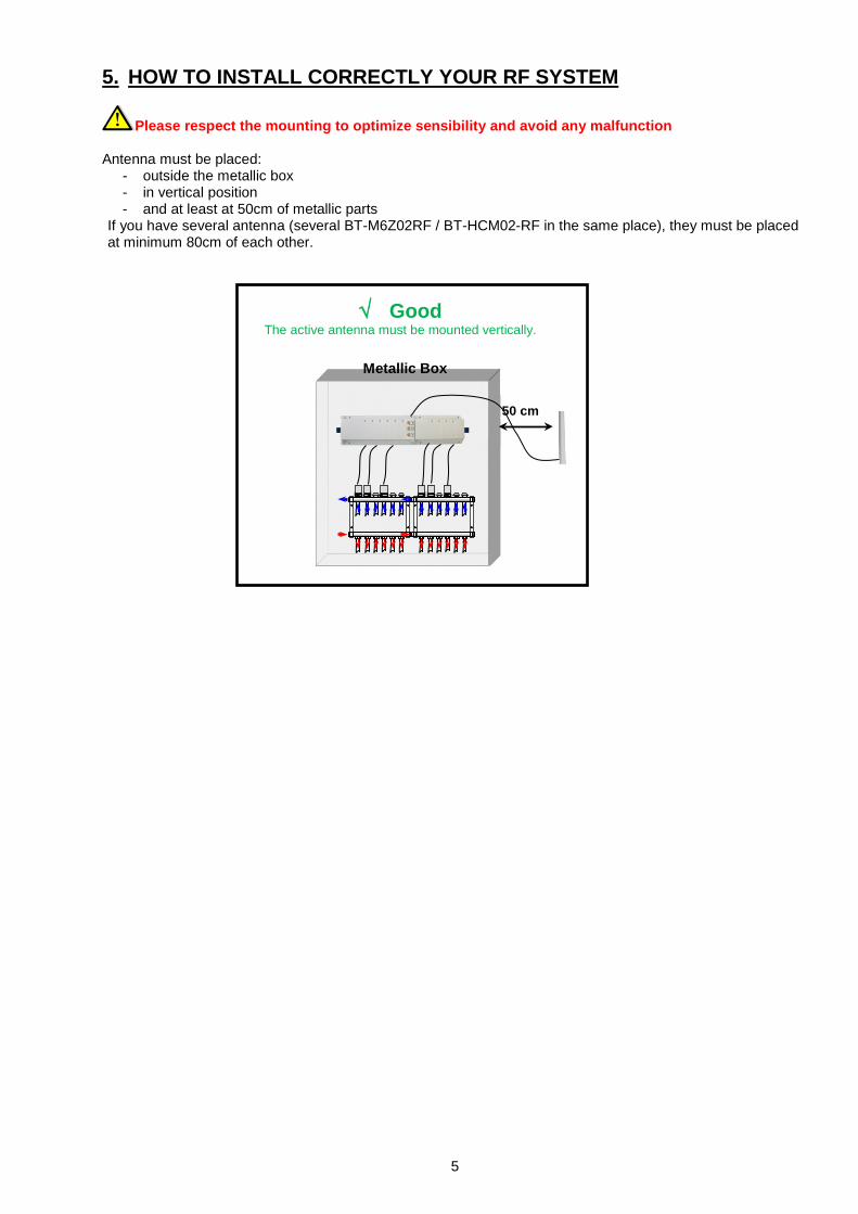
5. HOW TO INSTALL CORRECTLY YOUR RF SYSTEM
Please respect the mounting to optimize sensibility and avoid any malfunction Antenna must be placed:
- outside the metallic box - in vertical position - and at least at 50cm of metallic parts
If you have several antenna (several BT-M6Z02RF / BT-HCM02-RF in the same place), they must be placed at minimum 80cm of each other.
√ Good The active antenna must be mounted vertically.
Metallic Box
50 cm
6
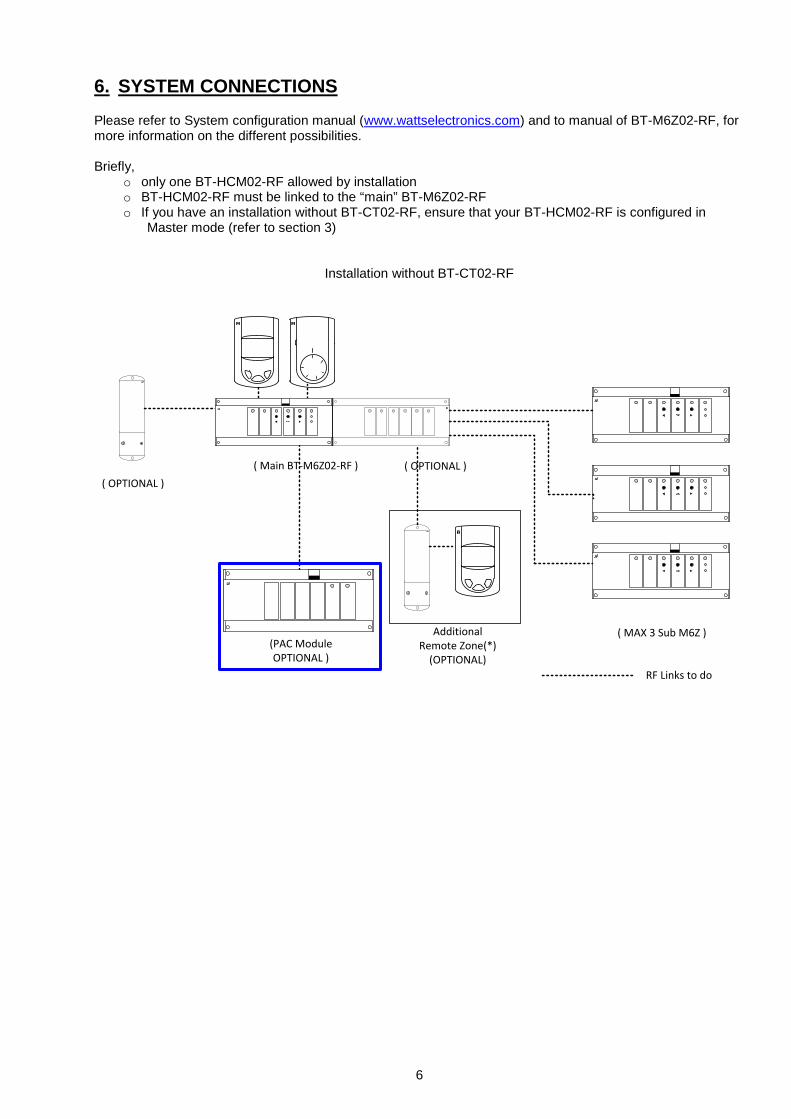
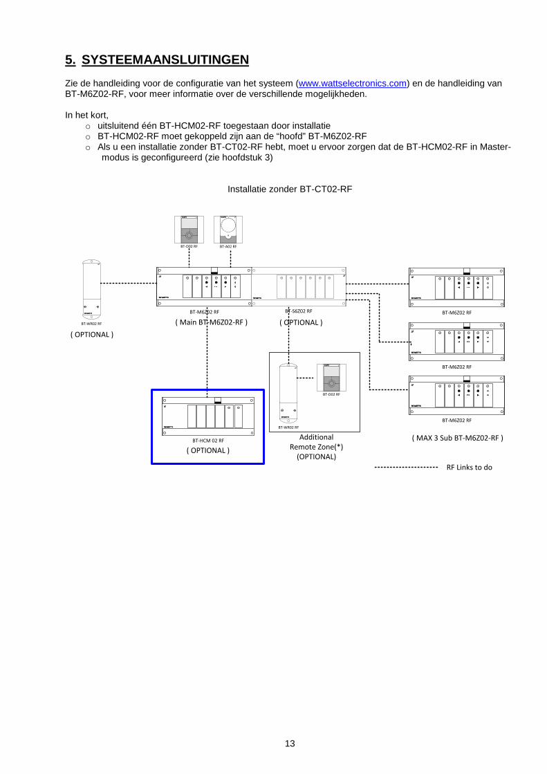
6. SYSTEM CONNECTIONS Please refer to System configuration manual (www.wattselectronics.com) and to manual of BT-M6Z02-RF, for more information on the different possibilities. Briefly,
o only one BT-HCM02-RF allowed by installation o BT-HCM02-RF must be linked to the “main” BT-M6Z02-RF o If you have an installation without BT-CT02-RF, ensure that your BT-HCM02-RF is configured in
Master mode (refer to section 3)
Installation without BT-CT02-RF
( OPTIONAL )
(PAC Module OPTIONAL )
( OPTIONAL )
RF Links to do
Additional Remote Zone(*)
(OPTIONAL)
( MAX 3 Sub M6Z )
( Main BT-M6Z02-RF )
30
5
2520
15
10
7
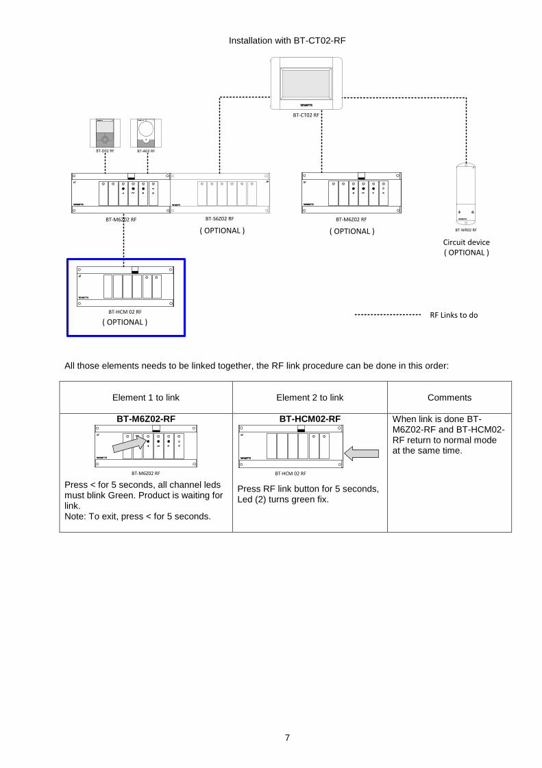
Installation with BT-CT02-RF
BT-M6Z02 RF
BT-A02 RFBT-D02 RF
BT-HCM 02 RF
BT-S6Z02 RF
( OPTIONAL )
( OPTIONAL )
RF Links to do
BT-M6Z02 RF
BT-WR02 RF
Circuit device( OPTIONAL )
( OPTIONAL )
BT-CT02 RF
All those elements needs to be linked together, the RF link procedure can be done in this order:
Element 1 to link
Element 2 to link
Comments
BT-M6Z02-RF
BT-M6Z02 RF Press < for 5 seconds, all channel leds must blink Green. Product is waiting for link. Note: To exit, press < for 5 seconds.
BT-HCM02-RF
BT-HCM 02 RF
Press RF link button for 5 seconds, Led (2) turns green fix.
When link is done BT-M6Z02-RF and BT-HCM02-RF return to normal mode at the same time.
8
7. FUNCTIONS - Heat Cool input signal (Master mode switch 1 OFF)
When BT-HCM02 RF is in master mode for Heat/Cool, it decides if system is in heating mode or in cooling mode according to H&C imputs:
o Free contact input (manual switch or automatic from heat pump): if contact is opened then system is in heating mode if contact is closed then system is in cooling mode
o NTC Sensor 10K connected on the water inlet: if temperature > 24°C, system is in heating mode if temperature < 20°C, system is in cooling mode
Heating or cooling switch is delayed 2sec / 5minutes depending on the state of DIP switch 3. For system initialisation, when you are using a water sensor, unplug the sensor to trigger the system in the proper mode, then plug the sensor.
- Heat output: (free contact) Heat relay is closed when system is in heating mode.
- Cold output: (free contact) Cold relay is closed when system is in cooling mode.
- Dehumidifier output: (free contact) Humidity relay is closed when
o system is in cooling mode o AND there is a detection of humidity on at least one of thermostat with humidity sensor BT-D(P)02-
RF RH (refer to its instruction manual to have more information about humidity configuration) o AND humidity function is activate (DIP switch 2 OFF)
- 230V Pump output: (live contact)
230V relay is closed when there is at least one demand on the system, a typpical application to this output is Pump output. Note: to use this output, installer needs to strap the “SECU” connector
1. GEBRUIKERSHANDLEIDING Verwarmings- & koelingsmodule BT-HCM02-RF is speciaal ontworpen voor de bediening van uw vloerverwarmings-/koelingssysteem. Zij is d.m.v. RF (868MHz) met uw installatie verbonden via de BT-M6Z02 RF. BT-HCM02-RF kan een signaal voor verwarmen/koelen uit verschillende bronnen krijgen: - ingang vrij contact vanaf uitgang warmtepomp - ingang vrij contact voor handmatige schakeling - een NTC-sensor om de watertemperatuur bij de inlaat te meten - vanaf de BT-CT02-RF (BT-HCM02-RF geconfigureerd in slave-modus) BT-HCM02-RF heeft ook enkele uitgangen voor: - algemene pomp van het systeem - Uitgangen ontvochtiger, mocht er een afwijkende vochtigheid zijn waargenomen (in samenwerking met BT-
D(P)02-RF RH thermostaten) - Uitgangen voor verwarmen en koelen om de installatie naar verwarmen / koelen te schakelen
2. TECHNISCHE SPECIFICATIES
BT-HCM02 RF Gebruikstemperatuur 0°C tot 50°C Voedingsspanning 230VAC +- 10% 50Hz
Uitgangen: Verwarmen en koelen Ontvochtiger Pomp
2 x Relais => 5A / 250VAC (vrij contact) 1 x Relais => 5A / 250VAC (vrij contact) 1 x Relais => 5 A / 230 VAC (L, N)
Ingang: HC
HC-ingang kan worden aangesloten op • een vrij contact voor een handmatige schakeling of
uitgang warmtepomp • een CTN 10K om de watertemperatuur te meten
Radiofrequentie
868,3 MHz <10mW. Bereik circa 180 meter zonder obstakels. Bereik circa 50 meters in een woonomgeving.
CE-richtlijnen Dit product voldoet aan de Europese Richtlijnen.
R&TTE 1999/5/EG LVD 2006/95/EG
EMC 2004/108/EG RoHS 2011/65/EU
Beschermingsgraad IP30 Combinatie Uitsluitend met BT-M6Z02-RF
10
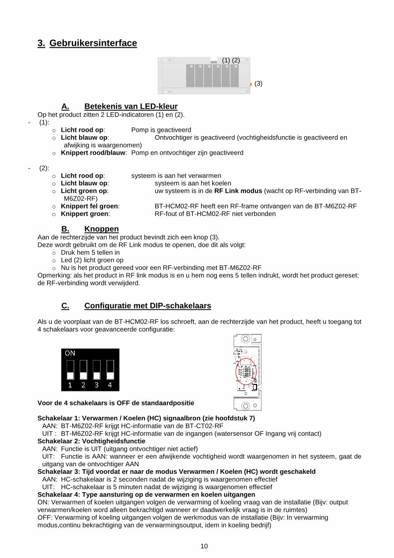
3. Gebruikersinterface
A. Betekenis van LED-kleur Op het product zitten 2 LED-indicatoren (1) en (2).
- (1): o Licht rood op: Pomp is geactiveerd o Licht blauw op: Ontvochtiger is geactiveerd (vochtigheidsfunctie is geactiveerd en
afwijking is waargenomen) o Knippert rood/blauw: Pomp en ontvochtiger zijn geactiveerd
- (2):
o Licht rood op: systeem is aan het verwarmen o Licht blauw op: systeem is aan het koelen o Licht groen op: uw systeem is in de RF Link modus (wacht op RF-verbinding van BT-
M6Z02-RF) o Knippert fel groen: BT-HCM02-RF heeft een RF-frame ontvangen van de BT-M6Z02-RF o Knippert groen: RF-fout of BT-HCM02-RF niet verbonden
B. Knoppen Aan de rechterzijde van het product bevindt zich een knop (3). Deze wordt gebruikt om de RF Link modus te openen, doe dit als volgt:
o Druk hem 5 tellen in o Led (2) licht groen op o Nu is het product gereed voor een RF-verbinding met BT-M6Z02-RF
Opmerking: als het product in RF link modus is en u hem nog eens 5 tellen indrukt, wordt het product gereset: de RF-verbinding wordt verwijderd.
C. Configuratie met DIP-schakelaars Als u de voorplaat van de BT-HCM02-RF los schroeft, aan de rechterzijde van het product, heeft u toegang tot 4 schakelaars voor geavanceerde configuratie:
Voor de 4 schakelaars is OFF de standaardpositie Schakelaar 1: Verwarmen / Koelen (HC) signaalbron (zie hoofdstuk 7)
AAN: BT-M6Z02-RF krijgt HC-informatie van de BT-CT02-RF UIT : BT-M6Z02-RF krijgt HC-informatie van de ingangen (watersensor OF Ingang vrij contact)
Schakelaar 2: Vochtigheidsfunctie AAN: Functie is UIT (uitgang ontvochtiger niet actief) UIT: Functie is AAN: wanneer er een afwijkende vochtigheid wordt waargenomen in het systeem, gaat de uitgang van de ontvochtiger AAN
Schakelaar 3: Tijd voordat er naar de modus Verwarmen / Koelen (HC) wordt geschakeld AAN: HC-schakelaar is 2 seconden nadat de wijziging is waargenomen effectief UIT: HC-schakelaar is 5 minuten nadat de wijziging is waargenomen effectief
Schakelaar 4: Type aansturing op de verwarmen en koelen uitgangen ON: Verwarmen of koelen uitgangen volgen de verwarming of koeling vraag van de installatie (Bijv: output verwarmen/koelen word alleen bekrachtigd wanneer er daadwerkelijk vraag is in de ruimtes) OFF: Verwarming of koeling uitgangen volgen de werkmodus van de installatie (Bijv: In verwarming modus,continu bekrachtiging van de verwarmingsoutput, idem in koeling bedrijf)
(1) (2)
(3)
11
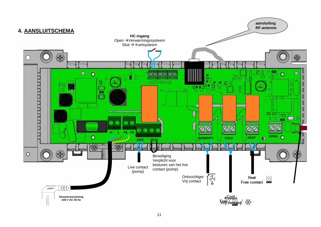
4. AANSLUITSCHEMA
aansluiting RF-antenne
HC-ingang Open Verwarmingssysteem
Sluit Koelsysteem
Ontvochtiger Vrij contact
Live contact (pomp)
Beveiliging Verplicht voor besturen van het live contact (pomp)
Koelen Vrij contact
Stroomvoorziening 230 V AC 50 Hz
12
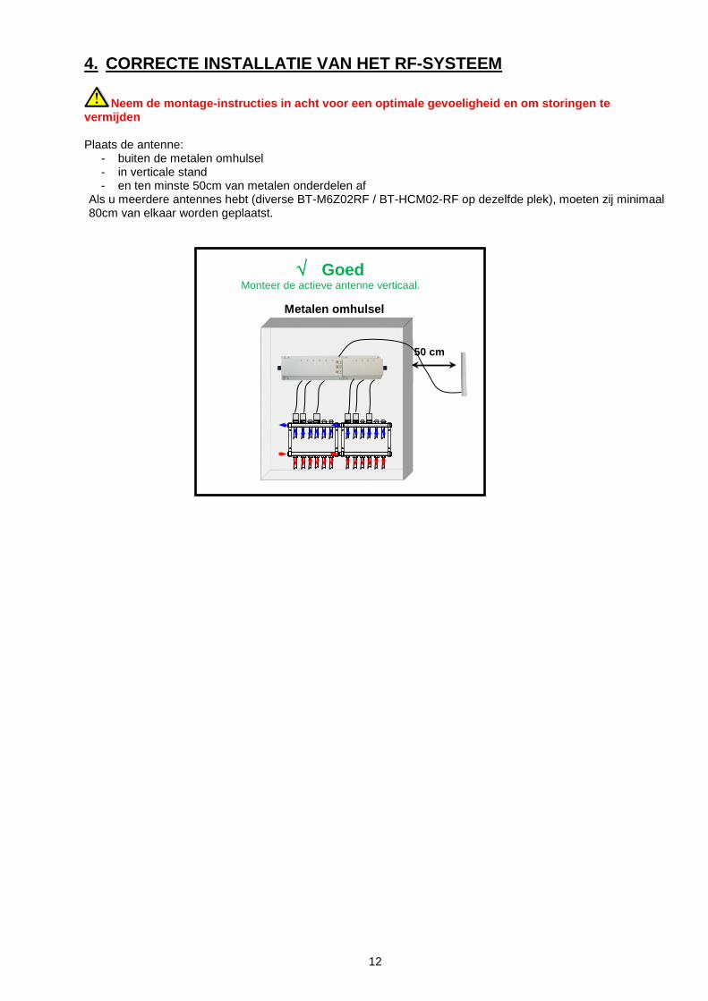
4. CORRECTE INSTALLATIE VAN HET RF-SYSTEEM
Neem de montage-instructies in acht voor een optimale gevoeligheid en om storingen te vermijden Plaats de antenne:
- buiten de metalen omhulsel - in verticale stand - en ten minste 50cm van metalen onderdelen af
Als u meerdere antennes hebt (diverse BT-M6Z02RF / BT-HCM02-RF op dezelfde plek), moeten zij minimaal 80cm van elkaar worden geplaatst.
√ Goed Monteer de actieve antenne verticaal.
Metalen omhulsel
50 cm
13
5. SYSTEEMAANSLUITINGEN Zie de handleiding voor de configuratie van het systeem (www.wattselectronics.com) en de handleiding van BT-M6Z02-RF, voor meer informatie over de verschillende mogelijkheden. In het kort,
o uitsluitend één BT-HCM02-RF toegestaan door installatie o BT-HCM02-RF moet gekoppeld zijn aan de “hoofd” BT-M6Z02-RF o Als u een installatie zonder BT-CT02-RF hebt, moet u ervoor zorgen dat de BT-HCM02-RF in Master-
modus is geconfigureerd (zie hoofdstuk 3)
Installatie zonder BT-CT02-RF
BT-M6Z02 RF
BT-A02 RFBT-D02 RF
BT-HCM 02 RF
BT-WR02 RF
BT-D02 RF
BT-WR02 RF
BT-S6Z02 RF
( OPTIONAL )
( OPTIONAL )
( OPTIONAL )
RF Links to do
BT-M6Z02 RF
BT-M6Z02 RF
BT-M6Z02 RF
Additional Remote Zone(*)
(OPTIONAL)
( MAX 3 Sub BT-M6Z02-RF )
( Main BT-M6Z02-RF )
14
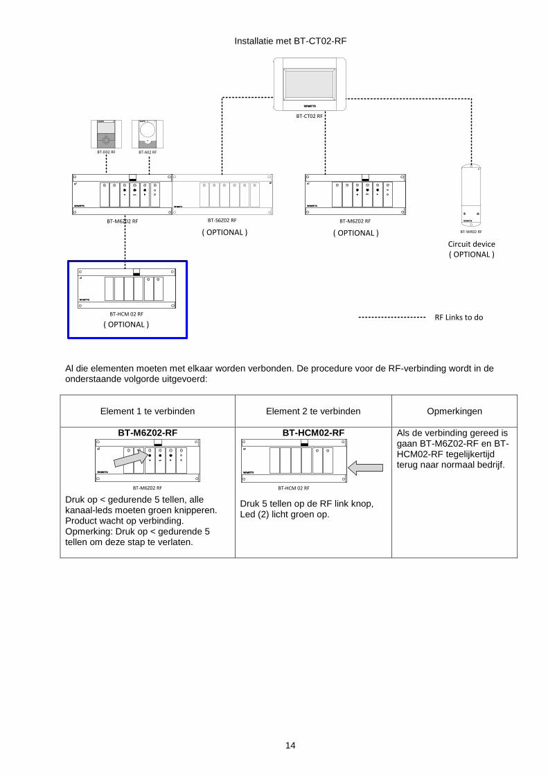
Installatie met BT-CT02-RF
BT-M6Z02 RF
BT-A02 RFBT-D02 RF
BT-HCM 02 RF
BT-S6Z02 RF
( OPTIONAL )
( OPTIONAL )
RF Links to do
BT-M6Z02 RF
BT-WR02 RF
Circuit device( OPTIONAL )
( OPTIONAL )
BT-CT02 RF
Al die elementen moeten met elkaar worden verbonden. De procedure voor de RF-verbinding wordt in de onderstaande volgorde uitgevoerd:
Element 1 te verbinden
Element 2 te verbinden
Opmerkingen
BT-M6Z02-RF
BT-M6Z02 RF Druk op < gedurende 5 tellen, alle kanaal-leds moeten groen knipperen. Product wacht op verbinding. Opmerking: Druk op < gedurende 5 tellen om deze stap te verlaten.
BT-HCM02-RF
BT-HCM 02 RF
Druk 5 tellen op de RF link knop, Led (2) licht groen op.
Als de verbinding gereed is gaan BT-M6Z02-RF en BT-HCM02-RF tegelijkertijd terug naar normaal bedrijf.
15
6. FUNCTIES - Verwarmen Koelen ingangssignaal (Master-modus schakelaar 1 UIT)
Als BT-HCM02 RF in master-modus is voor verwarmen/koelen, beslist deze of het systeem verwarmt of koelt in overeenstemming met de H&C-ingangen:
o Vrij contact ingang (handmatige schakeling of automatisch vanaf warmtepomp): als contact is geopend is het systeem in verwarmingsmodus als contact is gesloten is het systeem in koelmodus
o NTC Sensor 10K aangesloten op de waterinlaat: als temperatuur > 24°C, is het systeem niet in verwarmingsmodus als temperatuur < 20°C, is het systeem niet in koelmodus
Schakeling tussen verwarmen of koelen wordt 2sec / 5minuten vertraagd, afhankelijk van de status van DIP-schakelaar 3. Om het systeem te initialiseren, als u een watersensor gebruikt, moet u de sensor lostrekken om het systeem in de juiste modus te triggeren, en vervolgens de sensor weer aansluiten.
- Warmte-uitgang: (vrij contact) Warmte-relais is gesloten wanneer het systeem in verwarmingsmodus is
- Koude-uitgang: (vrij contact) Koude-relais is gesloten wanneer het systeem in koelmodus is
- Ontvochtiger uitgang: (vrij contact) Vochtigheids-relais is gesloten wanneer
o het systeem in koelmodus is. o EN er sprake is van vochtigheidswaarneming op ten minste één van de thermostaten met
vochtigheidssensor BT-D(P)02-RF RH (zie de instructiehandleiding voor meer informatie over vochtigheidsconfiguratie)
o EN vochtigheidsfunctie is geactiveerd (DIP-schakelaar 2 UIT)
- 230V Pomp uitgang: (live contact) 230V relais is gesloten als er ten minste één vraag is op het systeem, een typische applicatie bij deze uitgang is Pompuitgang. Opmerking: om deze uitgang te gebruiken moet de installateur de “SECU” verbinden
1. Guide utilisateur Le module BT-HCM02 RF a été désigné pour contrôler votre système de plancher hydraulique chauffant et rafraichissant en RF (868 MHz) via le BT-M6Z02 RF. Le BT-HCM02-RF peut obtenir le signal de chauffage ou de rafraîchissement de différentes sources: - Entrée contact libre provenant de la pompe à chaleur - Entrée contact libre d’un interrupteur - Une sonde NTC qui mesure la température entrante de l’eau - D’une unité centrale BT-CT02 RF (BT-HCM02-RFconfiguré en mode esclave) BT-HCM02-RF a également des sorties à destination: - Du circulateur global du système (contact alimenté) - Du déshumidificateur en cas de détection d’humidité en association avec les thermostats BT-D(P)02 RH RF
(Contact alimenté) - De la pompe à chaleur ou de vannes motorisées afin de commuter l’installation en chauffage ou en
rafraichissement (contact libre)
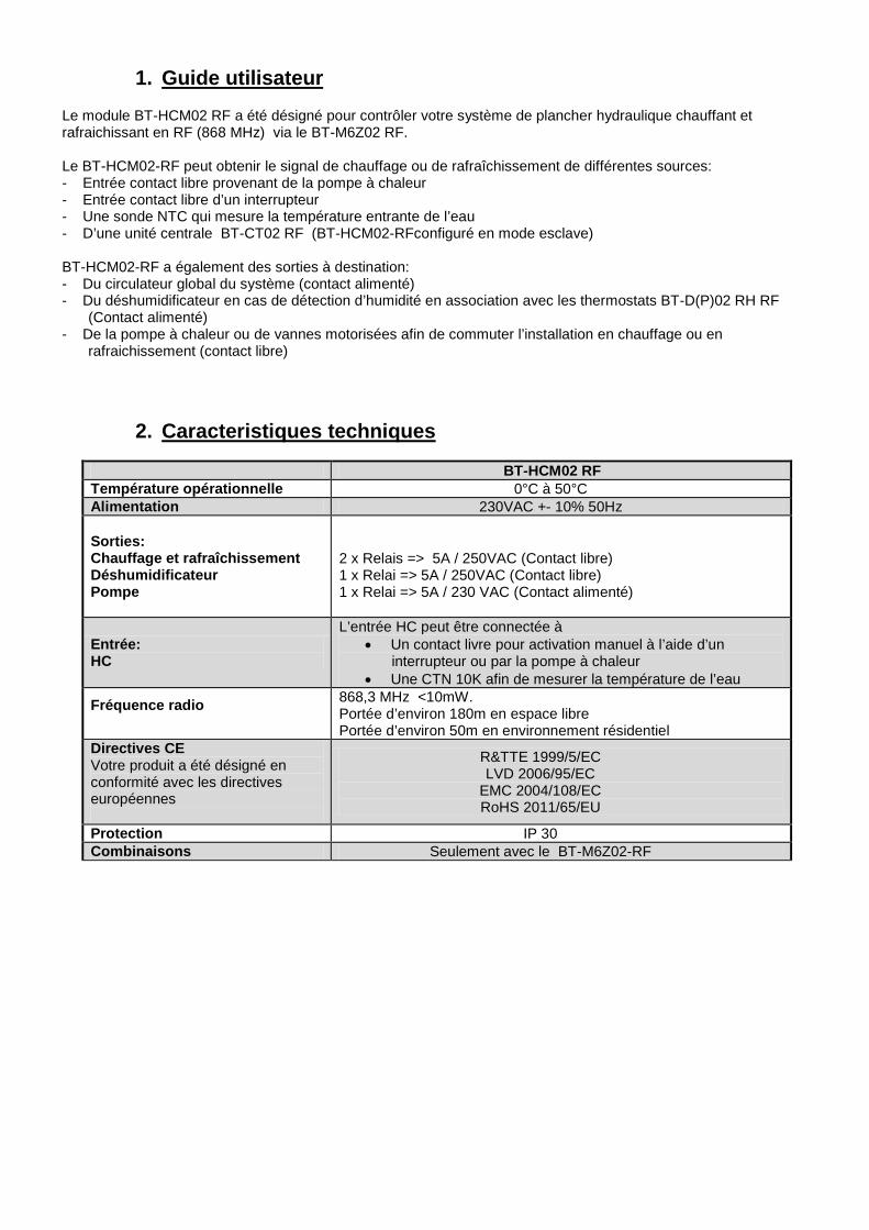
2. Caracteristiques techniques
BT-HCM02 RF Température opérationnelle 0°C à 50°C Alimentation 230VAC +- 10% 50Hz
Sorties: Chauffage et rafraîchissement Déshumidificateur Pompe
2 x Relais => 5A / 250VAC (Contact libre) 1 x Relai => 5A / 250VAC (Contact libre) 1 x Relai => 5A / 230 VAC (Contact alimenté)
Entrée: HC
L’entrée HC peut être connectée à • Un contact livre pour activation manuel à l’aide d’un
interrupteur ou par la pompe à chaleur • Une CTN 10K afin de mesurer la température de l’eau
Fréquence radio
868,3 MHz <10mW. Portée d’environ 180m en espace libre Portée d’environ 50m en environnement résidentiel
Directives CE Votre produit a été désigné en conformité avec les directives européennes
R&TTE 1999/5/EC LVD 2006/95/EC
EMC 2004/108/EC RoHS 2011/65/EU
Protection IP 30 Combinaisons Seulement avec le BT-M6Z02-RF
17
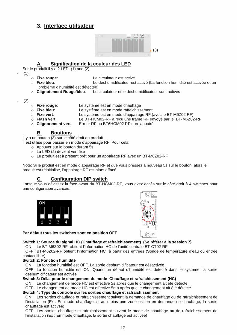
3. Interface utilsateur
A. Signification de la couleur des LED Sur le produiit il y a 2 LED (1) and (2).
- (1): o Fixe rouge: Le circulateur est activé o Fixe bleu: Le deshumidificateur est activé (La fonction humidité est activée et un
problème d’humidité est détectée) o Clignotement Rouge/bleu: Le circulateur et le déshumidificateur sont activés
- (2):
o Fixe rouge: Le système est en mode chauffage o Fixe bleu: Le système est en mode raffaichissement o Fixe vert: Le système est en mode d’appairage RF (avec le BT-M6Z02 RF) o Flash vert: Le BT-HCM02-RF a recu une trame RF envoyé par le BT-M6Z02-RF o Clignorement vert: Erreur RF ou BT6HCM02 RF non appairé
B. Bouttons Il y a un bouton (3) sur le côté droit du produit Il est utilisé pour passer en mode d’appairage RF. Pour cela:
o Appuyer sur le bouton durant 5s o La LED (2) devient vert fixe o Le produit est à présent prêt pour un appairage RF avec un BT-M6Z02-RF
Note: Si le produit est en mode d’appairage RF et que vous pressez à nouveau 5s sur le bouton, alors le produit est réinitialisé, l’appairage RF est alors effacé.
C. Configuration DIP switch Lorsque vous dévissez la face avant du BT-HCM02-RF, vous avez accès sur le côté droit à 4 switches pour une configuration avancée:
Par défaut tous les switches sont en position OFF Switch 1: Source du signal HC (Chauffage et rafraichissement) (Se référer à la session 7)
ON: Le BT-M6Z02-RF obtient l’information HC de l’unité centrale BT-CT02-RF OFF : BT-M6Z02-RF obtient l’information HC à partir des entrées (Sonde de température d’eau ou entrée
contact libre) Switch 2: Fonction humidité
ON : La fonction humidité est OFF. La sortie déshumidificateur est désactivée OFF : La fonction humidité est ON. Quand un défaut d’humidité est détecté dans le système, la sortie déshumidificateur est activée
Switch 3: Délai pour le changement de mode Chauffage et rafraichissement (HC) ON: Le changement de mode HC est effective 2s après que le changement ait été détecté. OFF: Le changement de mode HC est effective 5mn après que le changement ait été détecté.
Switch 4: Type de contrôle sur les sorties chauffage et rafraichissement ON: Les sorties chauffage et rafraichissement suivent la demande de chauffage ou de rafraichissement de l’installation (Ex : En mode chauffage, si au moins une zone est en en demande de chauffage, la sortie chauffage est activée) OFF: Les sorties chauffage et rafraichissement suivent le mode de chauffage ou de rafraichissement de l’installation (Ex : En mode chauffage, la sortie chauffage est activée)
(1) (2)
(3)
18
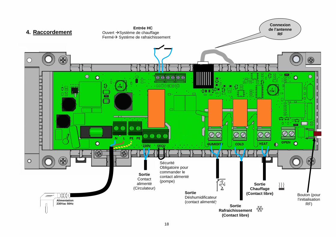
4. Raccordement
Connexion de l’antenne
RF Entrée HC
Ouvert Système de chauffage Fermé Système de rafraichissement
Sortie Contact alimenté
(Circulateur)
Bouton (pour l’initialisation
RF) Alimentation 230Vac 50Hz
Sécurité Obligatoire pour commander le contact alimenté (pompe)
Sortie Déshumidificateur (contact alimenté)
Sortie Rafraichissement
(Contact libre)
Sortie Chauffage
(Contact libre)
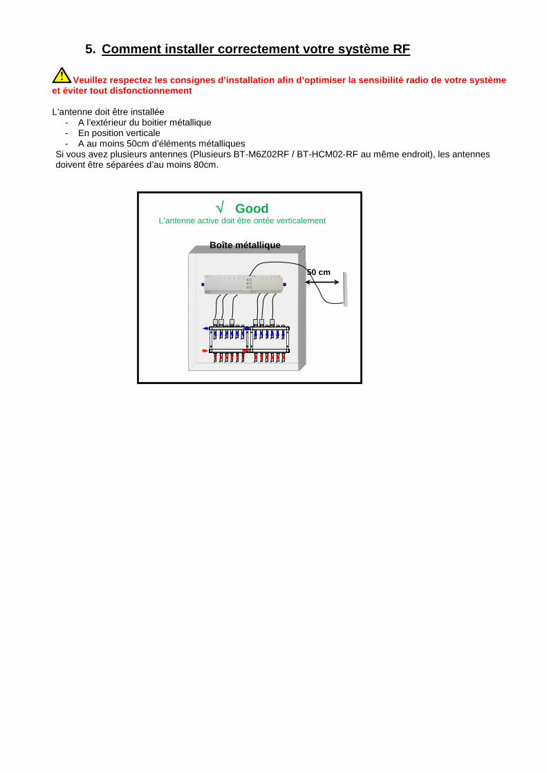
5. Comment installer correctement votre système RF
Veuillez respectez les consignes d’installation afin d’optimiser la sensibilité radio de votre système et éviter tout disfonctionnement L’antenne doit être installée
- A l’extérieur du boitier métallique - En position verticale - A au moins 50cm d’éléments métalliques
Si vous avez plusieurs antennes (Plusieurs BT-M6Z02RF / BT-HCM02-RF au même endroit), les antennes doivent être séparées d’au moins 80cm.
√ Good L’antenne active doit être ontée verticalement
Boîte métallique
50 cm
20
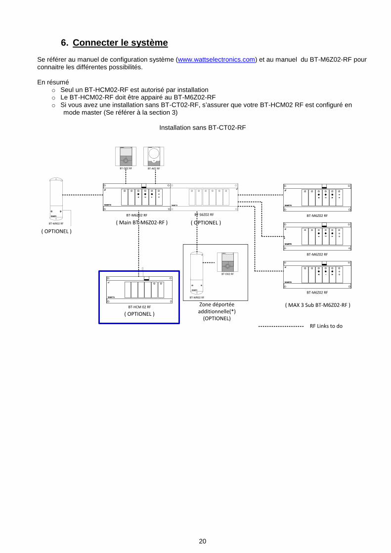
6. Connecter le système Se référer au manuel de configuration système (www.wattselectronics.com) et au manuel du BT-M6Z02-RF pour connaitre les différentes possibilités. En résumé
o Seul un BT-HCM02-RF est autorisé par installation o Le BT-HCM02-RF doit être appairé au BT-M6Z02-RF o Si vous avez une installation sans BT-CT02-RF, s’assurer que votre BT-HCM02 RF est configuré en
mode master (Se référer à la section 3)
Installation sans BT-CT02-RF
BT-M6Z02 RF
BT-A02 RFBT-D02 RF
BT-HCM 02 RF
BT-WR02 RF
BT-D02 RF
BT-WR02 RF
BT-S6Z02 RF
( OPTIONEL )
( OPTIONEL )
( OPTIONEL )
RF Links to do
BT-M6Z02 RF
BT-M6Z02 RF
BT-M6Z02 RF
Zone déportée additionnelle(*)
(OPTIONEL)
( MAX 3 Sub BT-M6Z02-RF )
( Main BT-M6Z02-RF )
21
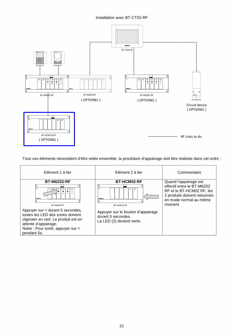
Installation avec BT-CT02-RF
BT-M6Z02 RF
BT-A02 RFBT-D02 RF
BT-HCM 02 RF
BT-S6Z02 RF
( OPTIONEL )
( OPTIONEL )
RF Links to do
BT-M6Z02 RF
BT-WR02 RF
Circuit device( OPTIONEL )
( OPTIONEL )
BT-CT02 RF
Tous ces éléments nécessitent d’être reliés ensemble, la procédure d’appairage doit être réalisée dans cet ordre :
Elément 1 à lier
Elément 2 à lier
Commentaire
BT-M6Z02-RF
BT-M6Z02 RF Appuyer sur < durant 5 secondes, toutes les LED des zones doivent clignoter en vert. Le produit est en attente d’appairage. Notre : Pour sortir, appuyer sur < pendant 5s.
BT-HCM02-RF
BT-HCM 02 RF
Appuyer sur le bouton d’appairage durant 5 secondes. La LED (2) devient verte.
Quand l’appairage est effectif entre le BT-M6Z02 RF et le BT-HCM02 RF, les 2 produits doivent retournés en mode normal au même moment
22
7. FONCTIONS
- Signal d’entrée chauffage raffraichissement (Mode Master switch 1 OFF) Quand le BT-HCM02 RF est en mode master pour le chauffage / raffraichissement, il décide du mode chauffage ou raffraichissment en fonction des entrées HC:
o Entrée contact libre (Interupteur manuel ou automatique par la pompe à chaleur): Si le contact est ouvert, le système est en mode chauffage Si le contact est fermé, le système est en mode raffraichissement
o Sonde NTC 10K mesurant la température de l’eau en entrée Si la temperature > 24°C, le système est en mode chauffage Si la temperature < 20°C, le système est en mode raffraichissement
Le basculement Chauffage/Raffraichissement est retardé de 2s /5mn suivant la valeur du DIP switch 3. A l’initilalisation du système, lorsque vous utilisez une sonde d’eau, déconnecté la sonde pour basculer le système dans le mode approprié, puis reconnecté la sonde.
- Sortie Chauffage: (contact libre) Le relais chauffage est fermé quand le système est en mode chauffage.
- Sortie raffraichissement: (contact libre) Le relais raffraichissement est fermé quand le système est en mode raffraichissement.
- Sortie déshumidificateur: (contact libre)
Le relais humidité est fermé quand o Le système est en mode rafraichissment o ET il y a une détection d’humidité dans au moins un thermostat embarquant un capteur d’humidité BT-
D02 RH Rf ou BT-DP02 RH RF (se référer à la notice des thermostats pour la configuration) o ET la fonction humidité est activée (DIP switch 2 OFF)
- 230V Sortie de circulateur: (contact alimenté)
Le relais 230V est fermé quand il y a au moins une demande de chauffe dans le système. Elle peut servir pour activer un circulateur. Note: Pour utiliser cette sortie, l’installeur doit s’assurer qu’un pont est raccordé au connecteur « SECU ».
23
1. GUIDA UTENTE Il modulo di riscaldamento e raffreddamento BT-HCM02-RF è studiato appositamente per controllare il sistema di riscaldamento e raffreddamento a pavimento. È collegato all'impianto RF (868MHz) attraverso il BT-M6Z02 RF. Il BT-HCM02-RF può ricevere il segnale di riscaldamento o raffreddamento da diversi punti: - contatto pulito in ingresso dall'uscita della pompa di calore; - contatto pulito in ingresso da un interruttore manuale; - sensore NTC per la misurazione della temperatura dell'acqua in ingresso; - dal BT-CT02-RF (BT-HCM02-RF configurato in modalità slave). Il BT-HCM02-RF è dotato inoltre di alcune uscite per: - La pompa dell'intero impianto. - Le uscite del deumidificatore in caso di rilevamento di problemi di umidità, in associazione con i termostati BT-
D(P)02-RF. - Le uscite Riscaldamento/Raffreddamento per commutare l'impianto da una funzione all'altra.
2. CARATTERISTICHE TECNICHE
BT-HCM02 RF Temperatura d'esercizio Da 0 a 50 °C Tensione d'alimentazione 230 VCA +/-10% 50 Hz
Uscite: Riscaldamento e raffreddamento Deumidificatore Pompa
2 x relè => 5 A/250 VCA (contatto pulito) 1 x relè => 5 A/250 VCA (contatto pulito) 1 x relè => 5 A/230 VCA (L, N)
Ingresso: HC
L'ingresso HC mostrato in Figura nel capitolo CABLAGGIO, è usato come consenso esterno per attivazione modalità Raffrescamento o Riscaldamento e può essere collegato ad:
• Un contatto pulito proveniente da un interruttore manuale o dall'uscita di una pompa di calore.
• Un sensore NTC 10K per la misurazione della temperatura dell'acqua all’interno delle tubazioni di mandata (PPLELE06019). Maggiori dettagli in capitolo. FUNZIONI:
Radiofrequenza
868,3 MHz <10 mW. Funzionamento a una distanza di circa 180 m in spazi aperti. Funzionamento a una distanza di circa 50 m in ambiente residenziale.
Direttive CE Il prodotto è stato progettato in conformità alle Direttive europee
R&TTE 1999/5/CE LVD 2006/95/CE
EMC 2004/108/CE RoHS 2011/65/UE
Protezione IP 30 Combinazione Solo con BT-M6Z02-RF
24
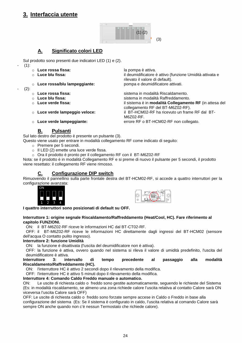
3. Interfaccia utente
A. Significato colori LED Sul prodotto sono presenti due indicatori LED (1) e (2).
- (1): o Luce rossa fissa: la pompa è attiva. o Luce blu fissa: il deumidificatore è attivo (funzione Umidità attivata e
rilevato il valore di default). o Luce rossa/blu lampeggiante: pompa e deumidificatore attivati.
- (2): o Luce rossa fissa: sistema in modalità Riscaldamento. o Luce blu fissa: sistema in modalità Raffreddamento. o Luce verde fissa: il sistema è in modalità Collegamento RF (in attesa del
collegamento RF del BT-M6Z02-RF). o Luce verde lampeggio veloce: il BT-HCM02-RF ha ricevuto un frame RF dal BT-
M6Z02-RF. o Luce verde lampeggiante: errore RF o BT-HCM02-RF non collegato.
B. Pulsanti Sul lato destro del prodotto è presente un pulsante (3). Questo viene usato per entrare in modalità collegamento RF come indicato di seguito:
o Premere per 5 secondi. o Il LED (2) emette una luce verde fissa. o Ora il prodotto è pronto per il collegamento RF con il BT-M6Z02-RF
Nota: se il prodotto è in modalità Collegamento RF e si preme di nuovo il pulsante per 5 secondi, il prodotto viene resettato: il collegamento RF viene rimosso.
C. Configurazione DIP switch Rimuovendo il pannellino sulla parte frontale destra del BT-HCM02-RF, si accede a quattro interruttori per la configurazione avanzata:
I quattro interruttori sono posizionati di default su OFF. Interruttore 1: origine segnale Riscaldamento/Raffreddamento (Heat/Cool, HC). Fare riferimento al capitolo FUNZIONI.
ON: il BT-M6Z02-RF riceve le informazioni HC dal BT-CT02-RF. OFF: il BT-M6Z02-RF riceve le informazioni HC direttamente dagli ingressi del BT-HCM02 (sensore
dell'acqua O contatto pulito ingresso). Interruttore 2: funzione Umidità
ON: la funzione è disattivata (l'uscita del deumidificatore non è attiva). OFF: la funzione è attiva, ovvero quando nel sistema si rileva il valore di umidità predefinito, l'uscita del deumidificatore è attiva.
Interruttore 3: intervallo di tempo precedente al passaggio alla modalità Riscaldamento/Raffreddamento (HC).
ON: l'interruttore HC è attivo 2 secondi dopo il rilevamento della modifica. OFF: l'interruttore HC è attivo 5 minuti dopo il rilevamento della modifica.
Interruttore 4: Comando Caldo Freddo manuale o automatico. ON: Le uscite di richiesta caldo o freddo sono gestite automaticamente, seguendo le richieste del Sistema (Es: in modalità riscaldamento, se almeno una zona richiede calore l’uscita relativa al contatto Calore sarà ON viceversa l’uscita Calore sarà OFF) OFF: Le uscite di richiesta caldo o freddo sono forzate sempre accese in Caldo o Freddo in base alla configurazione del sistema (Es: Se il sistema è configurato in caldo, l’uscita relativa al comando Calore sarà sempre ON anche quando non c’è nessun Termostato che richiede calore).
(1) (2)
(3)
25
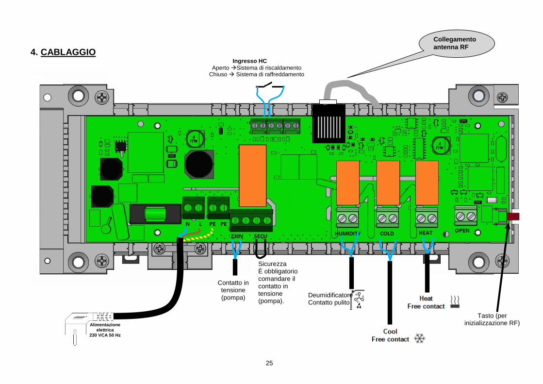
4. CABLAGGIO
Collegamento antenna RF
Ingresso HC Aperto Sistema di riscaldamento
Chiuso Sistema di raffreddamento
Deumidificatore Contatto pulito
Contatto in tensione (pompa)
Tasto (per inizializzazione RF) Alimentazione
elettrica 230 VCA 50 Hz
Sicurezza È obbligatorio comandare il contatto in tensione (pompa).
26
4. COME INSTALLARE CORRETTAMENTE IL SISTEMA RF
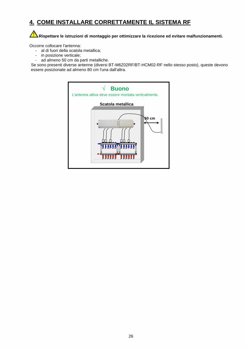
Rispettare le istruzioni di montaggio per ottimizzare la ricezione ed evitare malfunzionamenti. Occorre collocare l'antenna:
- al di fuori della scatola metallica; - in posizione verticale; - ad almeno 50 cm da parti metalliche.
Se sono presenti diverse antenne (diversi BT-M6Z02RF/BT-HCM02-RF nello stesso posto), queste devono essere posizionate ad almeno 80 cm l'una dall'altra.
√ Buono L'antenna attiva deve essere montata verticalmente.
Scatola metallica
50 cm
27
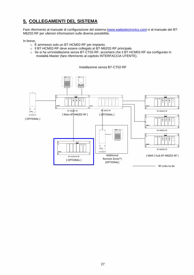
5. COLLEGAMENTI DEL SISTEMA Fare riferimento al manuale di configurazione del sistema (www.wattselectronics.com) e al manuale del BT-M6Z02-RF per ulteriori informazioni sulle diverse possibilità. In breve,
o È ammesso solo un BT-HCM02-RF per impianto. o Il BT-HCM02-RF deve essere collegato al BT-M6Z02-RF principale. o Se si ha un'installazione senza BT-CT02-RF, accertarsi che il BT-HCM02-RF sia configurato in
modalità Master (fare riferimento al capitolo INTERFACCIA UTENTE).
Installazione senza BT-CT02-RF
BT-M6Z02 RF
BT-A02 RFBT-D02 RF
BT-HCM 02 RF
BT-WR02 RF
BT-D02 RF
BT-WR02 RF
BT-S6Z02 RF
( OPTIONAL )
( OPTIONAL )
( OPTIONAL )
RF Links to do
BT-M6Z02 RF
BT-M6Z02 RF
BT-M6Z02 RF
Additional Remote Zone(*)
(OPTIONAL)
( MAX 3 Sub BT-M6Z02-RF )
( Main BT-M6Z02-RF )
28
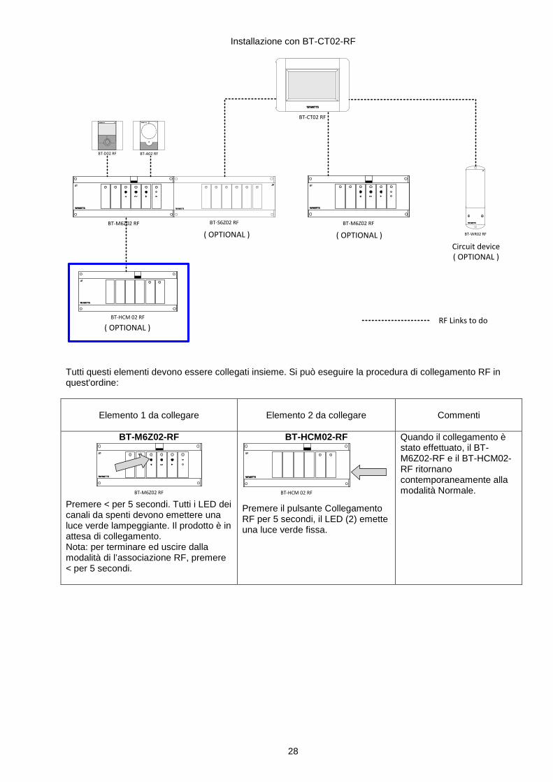
Installazione con BT-CT02-RF
BT-M6Z02 RF
BT-A02 RFBT-D02 RF
BT-HCM 02 RF
BT-S6Z02 RF
( OPTIONAL )
( OPTIONAL )
RF Links to do
BT-M6Z02 RF
BT-WR02 RF
Circuit device( OPTIONAL )
( OPTIONAL )
BT-CT02 RF
Tutti questi elementi devono essere collegati insieme. Si può eseguire la procedura di collegamento RF in quest'ordine:
Elemento 1 da collegare
Elemento 2 da collegare
Commenti
BT-M6Z02-RF
BT-M6Z02 RF Premere < per 5 secondi. Tutti i LED dei canali da spenti devono emettere una luce verde lampeggiante. Il prodotto è in attesa di collegamento. Nota: per terminare ed uscire dalla modalità di l’associazione RF, premere < per 5 secondi.
BT-HCM02-RF
BT-HCM 02 RF
Premere il pulsante Collegamento RF per 5 secondi, il LED (2) emette una luce verde fissa.
Quando il collegamento è stato effettuato, il BT-M6Z02-RF e il BT-HCM02-RF ritornano contemporaneamente alla modalità Normale.
29
6. FUNZIONI - Segnale in ingresso Riscaldamento/Raffreddamento (interruttore 1 modalità Master OFF)
Quando il BT-HCM02 RF è in modalità Master per Riscaldamento/Raffreddamento, decide se il sistema è in modalità Riscaldamento o Raffreddamento secondo gli input H&C:
o Input contatto pulito (interruttore manuale o automatico dalla pompa di calore): Se il contatto è aperto, il sistema è in modalità Riscaldamento. Se il contatto è chiuso, il sistema è in modalità Raffreddamento.
o Il sensore NTC 10K è collegato all'ingresso dell'acqua: Se la temperatura è > 24 °C, il sistema è in modalità Riscaldamento. Se la temperatura è < 20 °C, il sistema è in modalità Raffreddamento.
L'interruttore di riscaldamento o raffreddamento ha 2 s/5 min di ritardo a seconda dello stato del DIP switch 3. Per l'inizializzazione del sistema, quando si usa un sensore per l'acqua, scollegare il sensore per attivare il sistema nella modalità adeguata, quindi collegare il sensore.
- Uscita Riscaldamento: (contatto pulito) Quando il sistema è in modalità Riscaldamento, il relè del calore è chiuso.
- Uscita Raffreddamento: (contatto pulito) Quando il sistema è in modalità Raffreddamento, il relè del freddo è chiuso.
- Uscita deumidificatore: (contatto pulito) Il relè dell'umidità è chiuso quando
o il sistema è in modalità Raffreddamento o E almeno un termostato con sensore di umidità BT-D(P)02-RF RH rileva la presenza di umidità.
Fare riferimento al relativo manuale di istruzioni per avere maggiori informazioni sulla configurazione dell'umidità.
o E la funzione Umidità è attivata (DIP switch 2 OFF).
- Uscita pompa 230 V: (contatto in tensione) Il relè a 230 V è chiuso quando nel sistema arriva almeno una richiesta. Un'applicazione tipica di quest'uscita è il collegamento della pompa. Nota: per usare quest'uscita, l'installatore deve ponticellare il connettore "SECU".

30

31

32
PPLIMW15289Ba


![K32 DN 20 - viessmann.com · 2015/02 9932053VIE0x-mub-fr – V01 7 3.2.2 Découpleur hydraulique [Expert] ... 14 9932053VIE0x-mub-fr – V01 2015/02 3.2.4 Servomoteur de vanne 2 Nm](https://img.pdfslide.fr/doc/110x75/5b9aa2b009d3f22d2a8bc90b/k32-dn-20-201502-9932053vie0x-mub-fr-v01-7-322-decoupleur-hydraulique.jpg)