Embed Size (px)
Citation preview
GREX 2004 : NICE 27 - 29 octobre 2004
Pierre Touboul & Manuel RodriguesONERA - Physics and Instrumentation DepartmentBP 72 F-92322 Châtillon -
MISSION & INSTRUMENT
1 -P
ierr
e To
ubou
l-Ec
ole
d’ét
éG
éodé
sie
spat
iale
-2 s
epte
mbr
e20
02 -
2
MICROSCOPE Team
ONERA G. Bodovillé, G. Campergue, D. Chauvin, R. Chhun, P. Flinoise,B. Foulon, C. Gageant, E. Guiu, P. Kayser, D. Horrière, D. Hudson,V.Josselin, P.Leseur, M. Rodrigues (Payload PM), N. Tanguy, P. Touboul (PI)
OCA P. Berio, P. Exertier, G. Métris (Co-Pi), F. Mignard
ZARM Bremen H. Dittus (Co-I), H. Selig, S. Theil
PTB Brünswick V. Jaeger, F. Löffler
CNES Y. André, H. Conessa, J.B. Dubois (Mission PM), E. Fournier, S. Léon-Hirtz,B. Pouilloux, P. Prieur, P.G. Tizien, O. Vandermarcq, et al.
ESA D. Nicolini
1 -P
ierr
e To
ubou
l-Ec
ole
d’ét
éG
éodé
sie
spat
iale
-2 s
epte
mbr
e20
02 -
3
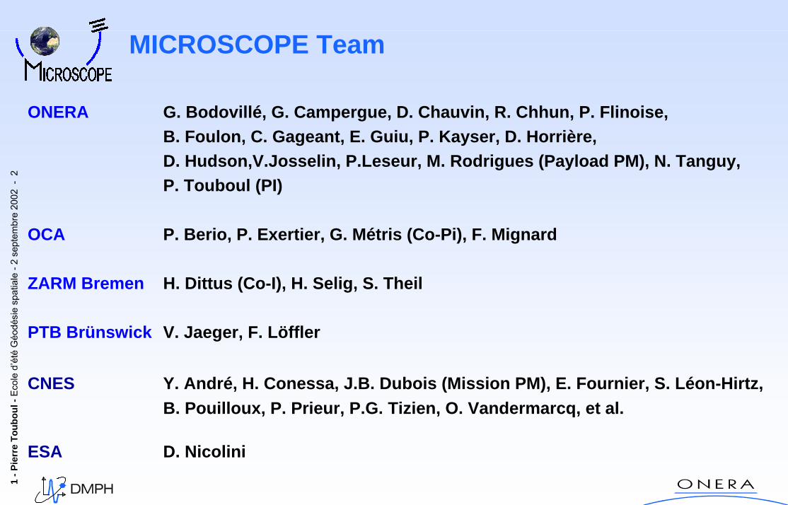
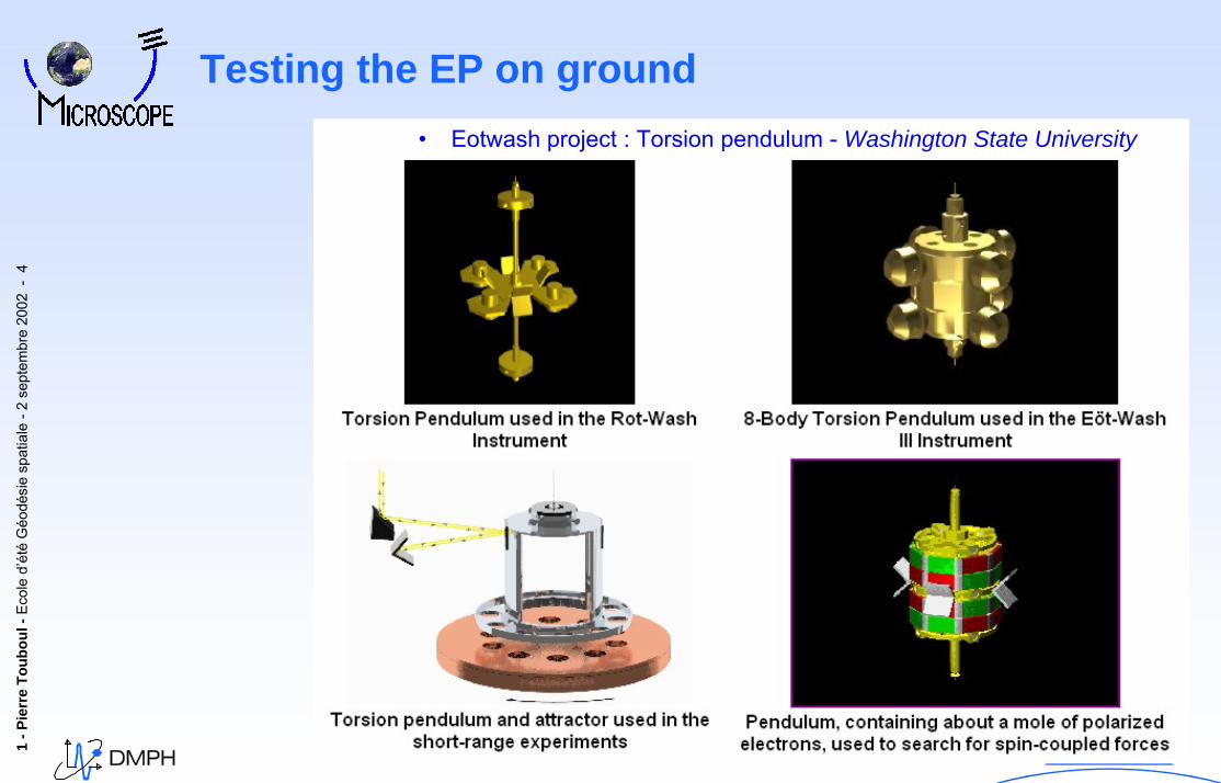
FromFrom Eötvös Eötvös ExperimentExperiment To:To:In In laboratorylaboratory::• Baessler S., Heckel B. , Alderberger E., Gundlach J.,…• Eotwash project : Torsion pendulum• Washington State University
Ref: Short-range tests of the equivalence principleG. L. Smith, C. D. Hoyle, J. H. Gundlach, E. G. Adelberger, B. R. Heckel, and H. E. SwansonDepartment of Physics, University of Washington, Seattle, Washington 98195PHYSICAL REVIEW D, VOLUME 61, 022001
13
wepMI
G
EI
G 104410MM
MM −×±=⎥
⎦
⎤⎢⎣
⎡−⎥
⎦
⎤⎢⎣
⎡)..(
[ ] Sun) thetoward ms109352aa 23MoonEarth (./ −−×=+
Testing the EP on ground
1 -P
ierr
e To
ubou
l-Ec
ole
d’ét
éG
éodé
sie
spat
iale
-2 s
epte
mbr
e20
02 -
4
Testing the EP on ground• Eotwash project : Torsion pendulum - Washington State University
1 -P
ierr
e To
ubou
l-Ec
ole
d’ét
éG
éodé
sie
spat
iale
-2 s
epte
mbr
e20
02 -
5
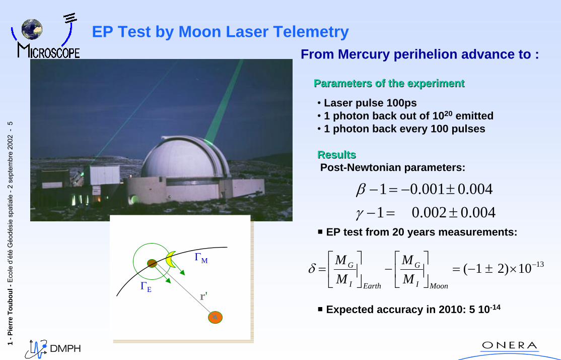
EP Test by Moon Laser TelemetryFrom Mercury perihelion advance to :
Parameters of the experimentParameters of the experiment
• Laser pulse 100ps• 1 photon back out of 1020 emitted• 1 photon back every 100 pulses
ResultsResultsPost-Newtonian parameters:
EP test from 20 years measurements:
Expected accuracy in 2010: 5 10-14
004.0002.01004.0001.01
±=−±−=−
γβ
1310)21( −×±−=⎥⎦
⎤⎢⎣
⎡−⎥
⎦
⎤⎢⎣
⎡=
MoonI
G
EarthI
G
MM
MMδ
ΓE
ΓM
r'
1 -P
ierr
e To
ubou
l-Ec
ole
d’ét
éG
éodé
sie
spat
iale
-2 s
epte
mbr
e20
02 -
6
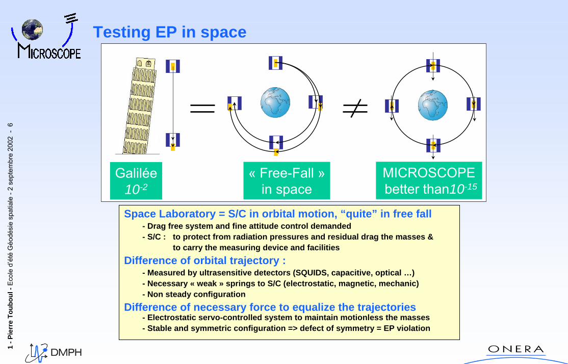
Testing EP in space
Space Laboratory = S/C in orbital motion, “quite” in free fall- Drag free system and fine attitude control demanded- S/C : to protect from radiation pressures and residual drag the masses &
to carry the measuring device and facilitiesDifference of orbital trajectory :
- Measured by ultrasensitive detectors (SQUIDS, capacitive, optical …) - Necessary « weak » springs to S/C (electrostatic, magnetic, mechanic)- Non steady configuration
Difference of necessary force to equalize the trajectories- Electrostatic servo-controlled system to maintain motionless the masses- Stable and symmetric configuration => defect of symmetry = EP violation
Galilée10-2
MICROSCOPEbetter than10-15
« Free-Fall »in space
1 -P
ierr
e To
ubou
l-Ec
ole
d’ét
éG
éodé
sie
spat
iale
-2 s
epte
mbr
e20
02 -
7
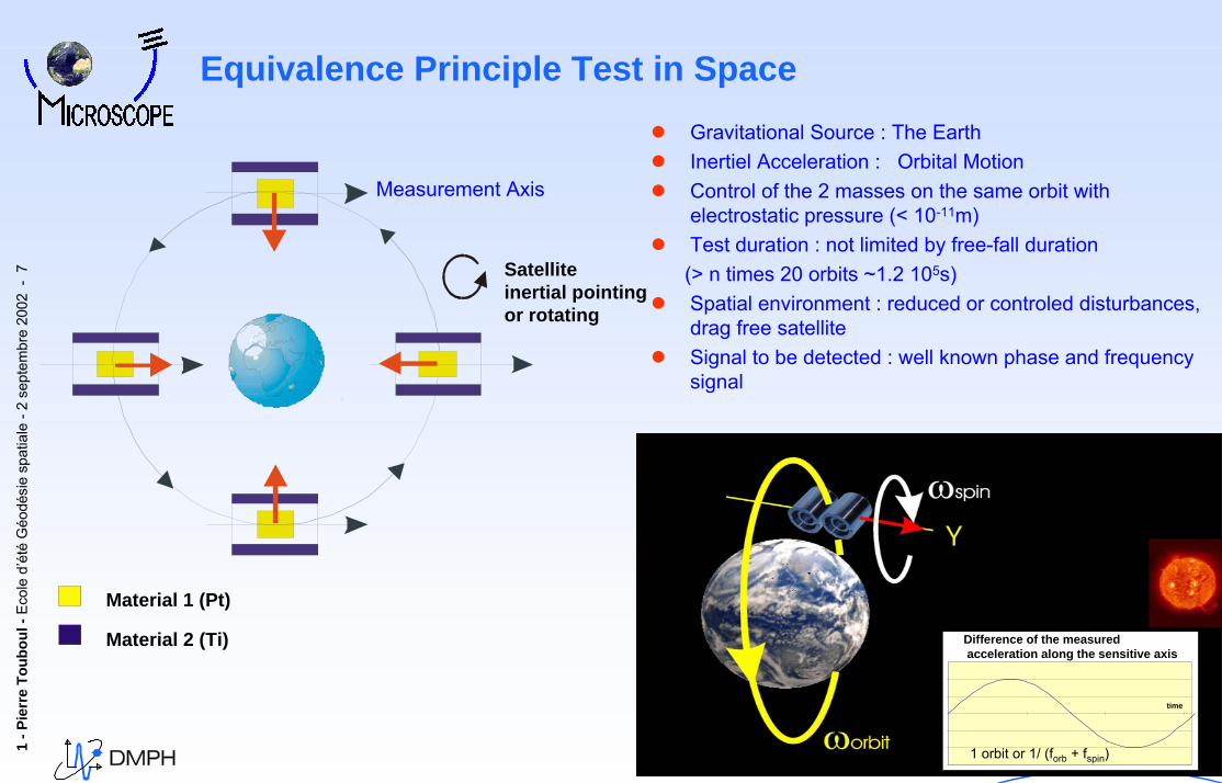
Equivalence Principle Test in SpaceGravitational Source : The EarthInertiel Acceleration : Orbital MotionControl of the 2 masses on the same orbit with electrostatic pressure (< 10-11m)Test duration : not limited by free-fall duration(> n times 20 orbits ~1.2 105s)Spatial environment : reduced or controled disturbances, drag free satelliteSignal to be detected : well known phase and frequency signal
Measurement Axis
Material 1 (Pt)
Material 2 (Ti)
Satelliteinertial pointingor rotating
Difference of the measuredacceleration along the sensitive axis
time
1 orbit or 1/ (forb + fspin)
Difference of the measuredacceleration along the sensitive axis
time
1 orbit or 1/ (forb + fspin)
1 -P
ierr
e To
ubou
l-Ec
ole
d’ét
éG
éodé
sie
spat
iale
-2 s
epte
mbr
e20
02 -
8
RS
ΩRI
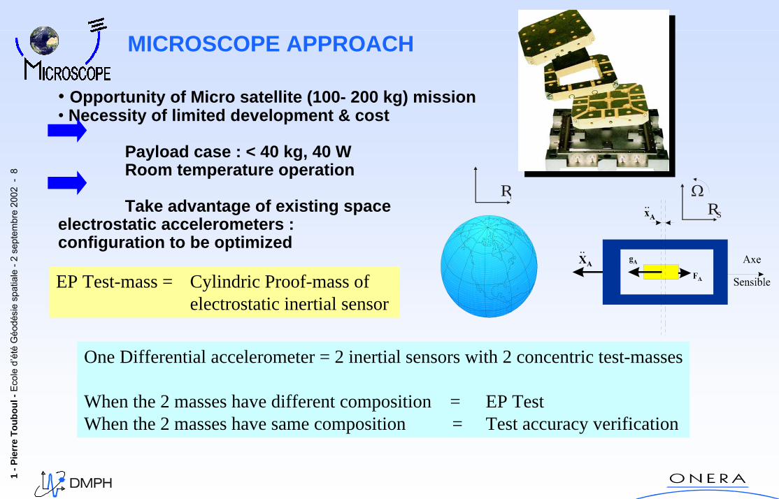
EP Test-mass = Cylindric Proof-mass ofelectrostatic inertial sensor
One Differential accelerometer = 2 inertial sensors with 2 concentric test-masses
When the 2 masses have different composition = EP TestWhen the 2 masses have same composition = Test accuracy verification
• Opportunity of Micro satellite (100- 200 kg) mission• Necessity of limited development & cost
Payload case : < 40 kg, 40 WRoom temperature operation
Take advantage of existing spaceelectrostatic accelerometers :configuration to be optimized
MICROSCOPE APPROACH
1 -P
ierr
e To
ubou
l-Ec
ole
d’ét
éG
éodé
sie
spat
iale
-2 s
epte
mbr
e20
02 -
9
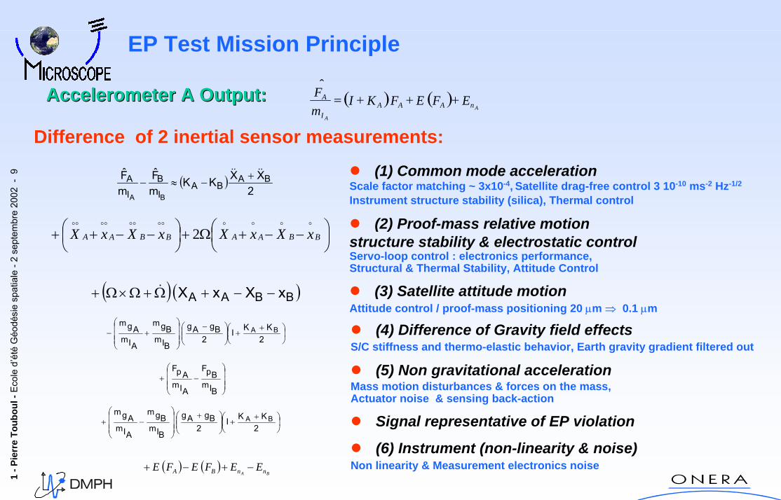
EP Test Mission Principle
(4) Difference of Gravity field effectsS/C stiffness and thermo-elastic behavior, Earth gravity gradient filtered out
(5) Non gravitational accelerationMass motion disturbances & forces on the mass, Actuator noise & sensing back-action
Signal representative of EP violation
(6) Instrument (non-linearity & noise)Non linearity & Measurement electronics noise
⎟⎠⎞
⎜⎝⎛ +
+⎟⎟⎠
⎞⎜⎜⎝
⎛ +
⎟⎟⎟
⎠
⎞
⎜⎜⎜
⎝
⎛−+
2KKI
2BgAg
BI
mBgm
AIm
AgmBA
Difference of 2 inertial sensor measurements:
( ) ( )BA nnBA EEFEFE −+−+
⎟⎠⎞
⎜⎝⎛ +
+⎟⎟⎠
⎞⎜⎜⎝
⎛ −
⎟⎟⎟
⎠
⎞
⎜⎜⎜
⎝
⎛+−
2KKI
2BgAg
BI
mBgm
AIm
AgmBA
⎟⎟⎟
⎠
⎞
⎜⎜⎜
⎝
⎛−+
BIm
BpF
AIm
ApF
(1) Common mode accelerationScale factor matching ~ 3x10⁻⁴, Satellite drag-free control 3 10-10 ms-2 Hz-1/2
Instrument structure stability (silica), Thermal control
(2) Proof-mass relative motionstructure stability & electrostatic controlServo-loop control : electronics performance, Structural & Thermal Stability, Attitude Control
(3) Satellite attitude motionAttitude control / proof-mass positioning 20 µm ⇒ 0.1 µm
( )2
XXKKmF
mF BA
BAI
B
I
A
BA
&&&& +−≈−
⎟⎠⎞
⎜⎝⎛ −−+Ω+⎟
⎠⎞
⎜⎝⎛ −−++ BBAABBAA xXxXxXxX
oooooooooooo
2
( ) ( )BBAA xXxX −−+Ω+Ω×Ω+ &
Accelerometer A Output:Accelerometer A Output: ( ) ( )A
A
nAAAI
A EFEFKImF +++=ˆ
1 -P
ierr
e To
ubou
l-Ec
ole
d’ét
éG
éodé
sie
spat
iale
-2 s
epte
mbr
e20
02 -
10
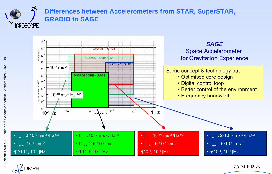
Differences between Accelerometers from STAR, SuperSTAR, GRADIO to SAGE
Same concept & technology but • Optimised core design• Digital control loop• Better control of the environment• Frequency bandwidth
• Γn :3·10-9 ms-2 /Hz1/2
• Γmax :10-4 ms-2
•[2·10-4; 10-1 ]Hz
• Γn :10-10 ms-2 /Hz1/2
• Γmax : 5·10-5 ms-2
•[10-4; 10-1 ]Hz
• Γn : 2·10-12 ms-2 /Hz1/2
• Γmax : 6·10-6 ms-2
•[5·10-3; 10-1 ]Hz
1 Hz10-5 Hz
10-6 ms-2
10-10 ms-2 Hz-1/2
MICROSCOPE – SAGE
• Γn :10-12 ms-2 /Hz1/2
• Γmax :2.5 10-7 ms-2
•[10-4; 5 10-3 ]Hz
SAGESpace Accelerometer
for Gravitation Experience
1 -P
ierr
e To
ubou
l-Ec
ole
d’ét
éG
éodé
sie
spat
iale
-2 s
epte
mbr
e20
02 -
11
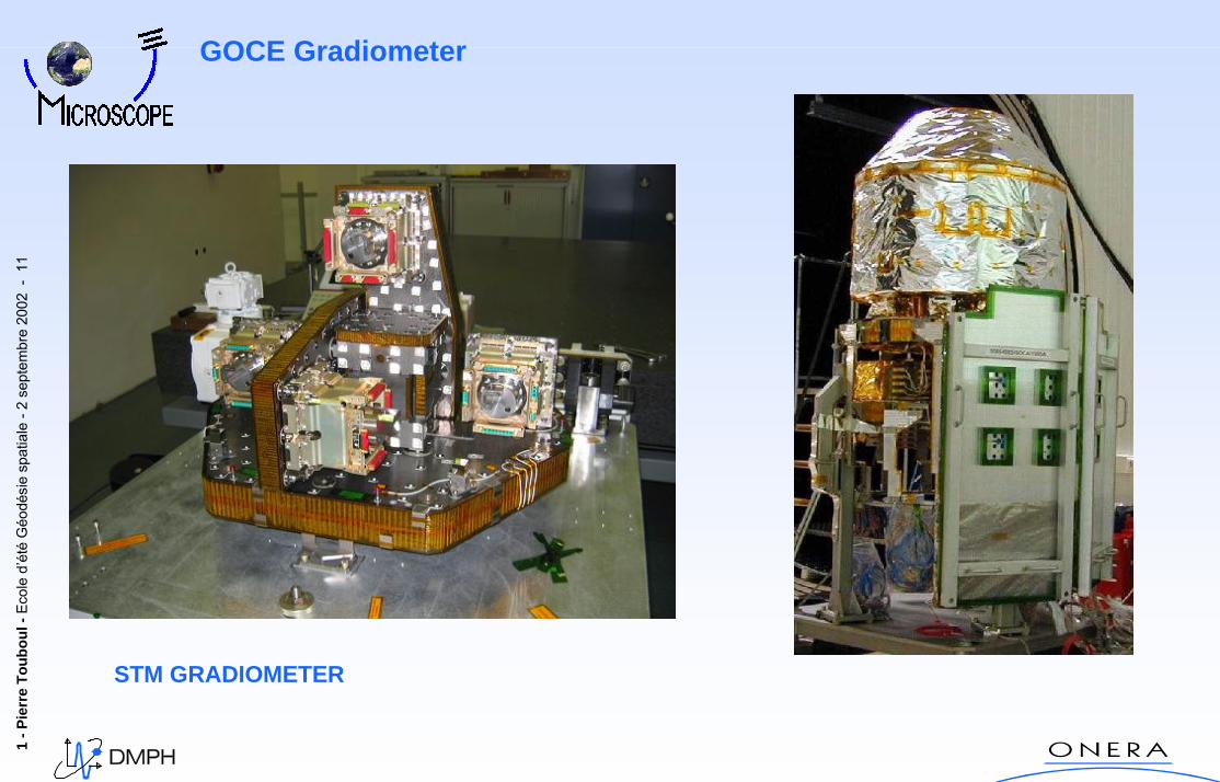
GOCE Gradiometer
STM GRADIOMETER
1 -P
ierr
e To
ubou
l-Ec
ole
d’ét
éG
éodé
sie
spat
iale
-2 s
epte
mbr
e20
02 -
12
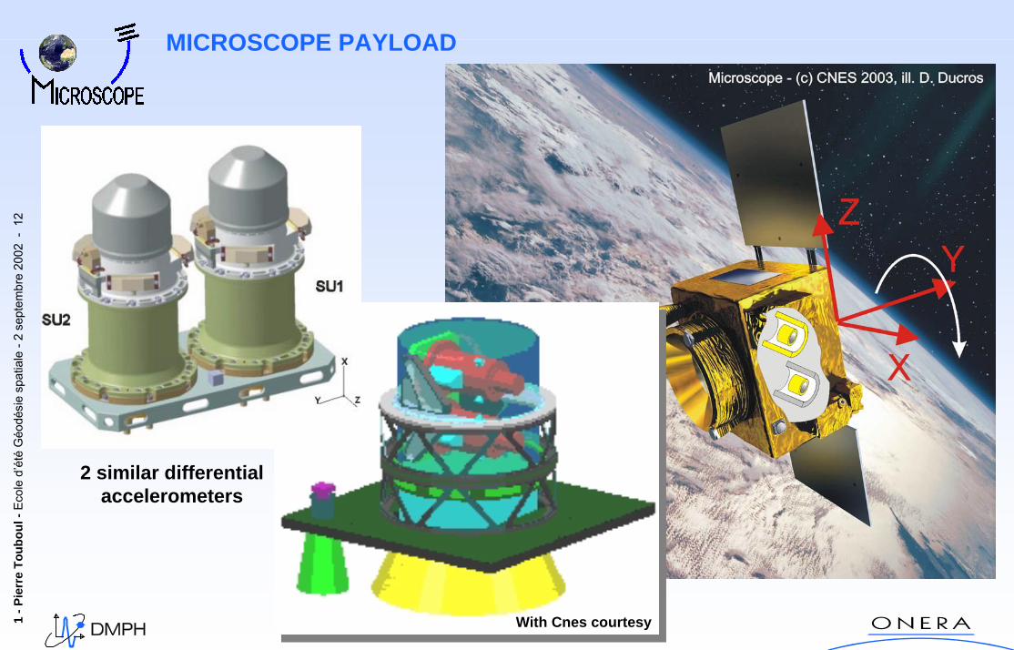
MICROSCOPE PAYLOAD
With Cnes courtesy
2 similar differentialaccelerometers
1 -P
ierr
e To
ubou
l-Ec
ole
d’ét
éG
éodé
sie
spat
iale
-2 s
epte
mbr
e20
02 -
13
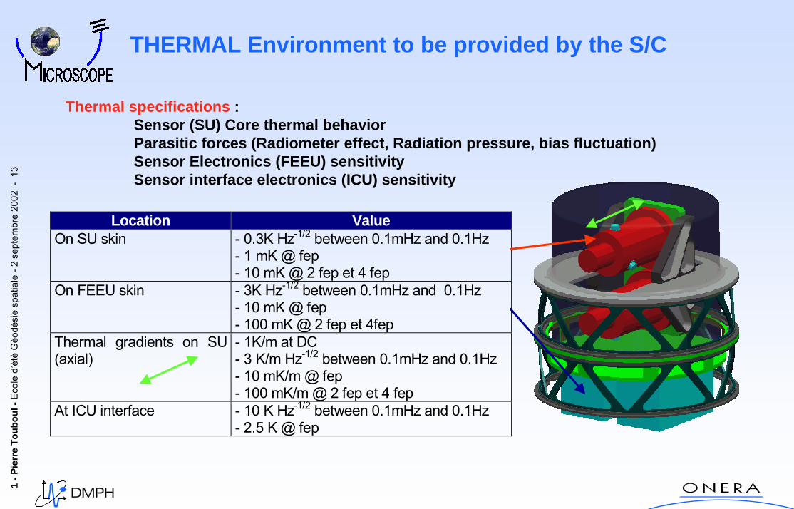
THERMAL Environment to be provided by the S/C
Thermal specifications : Sensor (SU) Core thermal behaviorParasitic forces (Radiometer effect, Radiation pressure, bias fluctuation)Sensor Electronics (FEEU) sensitivitySensor interface electronics (ICU) sensitivity
Location ValueOn SU skin - 0.3K Hz-1/2 between 0.1mHz and 0.1Hz
- 1 mK @ fep- 10 mK @ 2 fep et 4 fep
On FEEU skin - 3K Hz-1/2 between 0.1mHz and 0.1Hz- 10 mK @ fep- 100 mK @ 2 fep et 4fep
Thermal gradients on SU(axial)
- 1K/m at DC- 3 K/m Hz-1/2 between 0.1mHz and 0.1Hz- 10 mK/m @ fep- 100 mK/m @ 2 fep et 4 fep
At ICU interface - 10 K Hz-1/2 between 0.1mHz and 0.1Hz- 2.5 K @ fep
1 -P
ierr
e To
ubou
l-Ec
ole
d’ét
éG
éodé
sie
spat
iale
-2 s
epte
mbr
e20
02 -
14
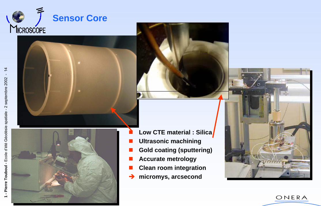
Sensor Core
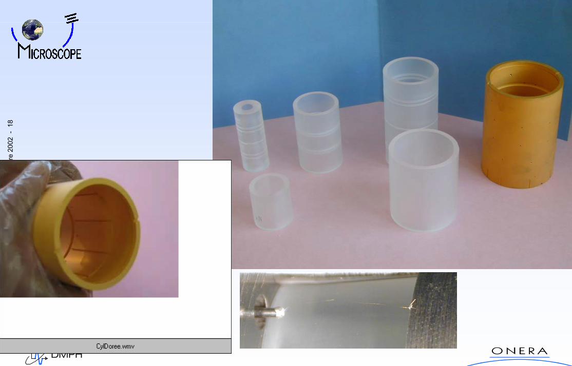
Low CTE material : SilicaUltrasonic machiningGold coating (sputtering)Accurate metrologyClean room integrationmicromys, arcsecond
1 -P
ierr
e To
ubou
l-Ec
ole
d’ét
éG
éodé
sie
spat
iale
-2 s
epte
mbr
e20
02 -
15
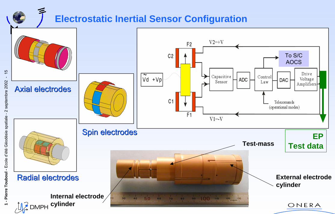
Electrostatic Inertial Sensor Configuration
Spin electrodesSpin electrodes EPTest data
To S/CAOCS
Axial electrodesAxial electrodes
Radial electrodesRadial electrodes
Internal electrode cylinder
Test-mass
External electrode cylinder
1 -P
ierr
e To
ubou
l-Ec
ole
d’ét
éG
éodé
sie
spat
iale
-2 s
epte
mbr
e20
02 -
16
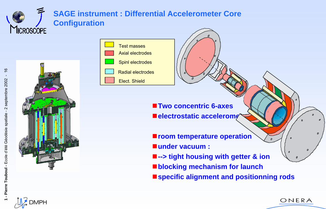
SAGE instrument : Differential Accelerometer CoreConfiguration
Two concentric 6-axeselectrostatic accelerometers
room temperature operationunder vacuum :--> tight housing with getter & ion blocking mechanism for launchspecific alignment and positionning rods
Radial electrodes
Elect. Shield
Spinl electrodes
Axial electrodesTest masses
1 -P
ierr
e To
ubou
l-Ec
ole
d’ét
éG
éodé
sie
spat
iale
-2 s
epte
mbr
e20
02 -
17
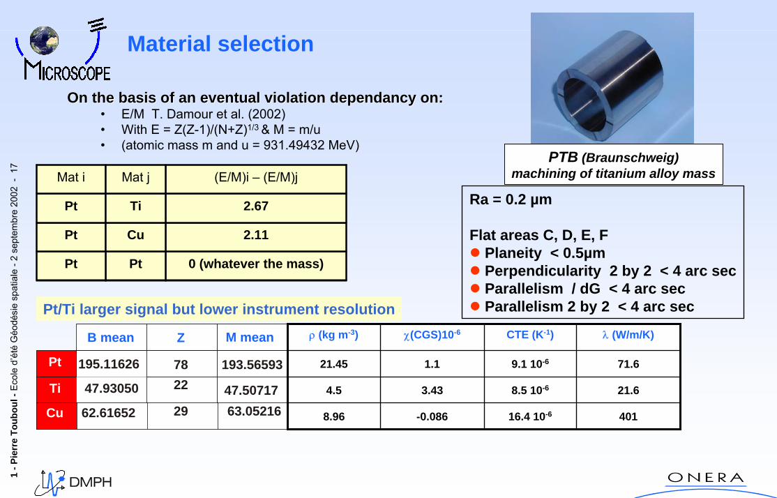
On On thethe basis basis ofof an an eventualeventual violation violation dependancydependancy on:on:• E/M T. Damour et al. (2002)• With E = Z(Z-1)/(N+Z)1/3 & M = m/u • (atomic mass m and u = 931.49432 MeV)
0 (whatever the mass)PtPt
Pt
Pt
Mat i
2.11Cu
2.67Ti
(E/M)i – (E/M)jMat j
Pt
Ti
B mean Z
47.93050 22 47.50717
195.11626 78 193.56593
Cu 62.61652 29 63.05216
M mean
16.4 10-6
8.5 10-6
9.1 10-6
CTE (K-1)
-0.086
3.43
1.1
χ(CGS)10-6
4018.96
21.64.5
71.621.45
λ (W/m/K)ρ (kg m-3)
Pt/Ti larger signal but lower instrument resolution
PTB (Braunschweig)machining of titanium alloy mass
Ra = 0.2 µm
Flat areas C, D, E, FPlaneity < 0.5µmPerpendicularity 2 by 2 < 4 arc secParallelism / dG < 4 arc secParallelism 2 by 2 < 4 arc sec
Material selection
1 -P
ierr
e To
ubou
l-Ec
ole
d’ét
éG
éodé
sie
spat
iale
-2 s
epte
mbr
e20
02 -
18
1 -P
ierr
e To
ubou
l-Ec
ole
d’ét
éG
éodé
sie
spat
iale
-2 s
epte
mbr
e20
02 -
19
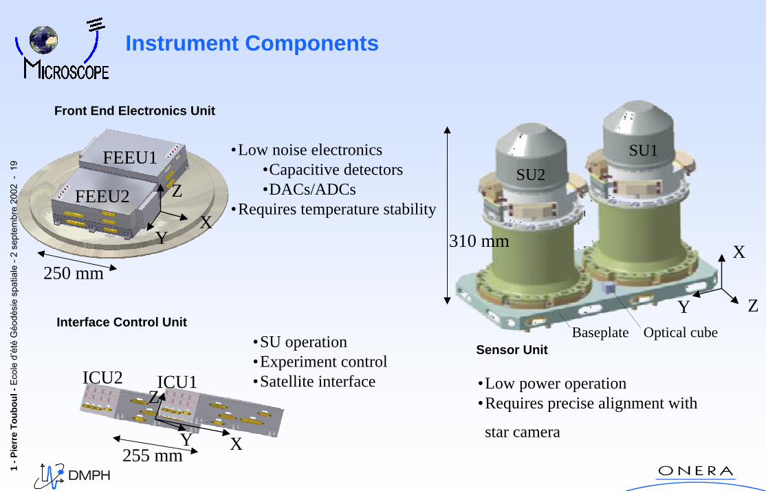
Instrument Components
Sensor Unit
Front End Electronics Unit
Interface Control Unit
•Low noise electronics •Capacitive detectors•DACs/ADCs
•Requires temperature stability
•SU operation•Experiment control•Satellite interface •Low power operation
•Requires precise alignment with
star camera
FEEU1
FEEU2
YX
Z
250 mm
ICU1ICU2
Y X
Z
Baseplate Optical cube
Y
X
Z
SU2SU1
310 mm
255 mm
1 -P
ierr
e To
ubou
l-Ec
ole
d’ét
éG
éodé
sie
spat
iale
-2 s
epte
mbr
e20
02 -
20
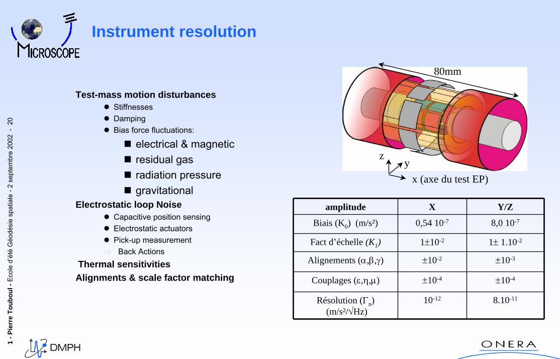
Instrument resolution
80mm
x (axe du test EP)
zy
Test-mass motion disturbancesStiffnessesDampingBias force fluctuations:
electrical & magneticresidual gasradiation pressuregravitational
Electrostatic loop NoiseCapacitive position sensingElectrostatic actuatorsPick-up measurement
⇒ Back ActionsThermal sensitivities
Alignments & scale factor matching
8.10-1110-12Résolution (Γn)(m/s²/√Hz)
±10-4±10-4Couplages (ε,η,µ)
±10-3±10-2Alignements (α,β,γ)
1± 1.10-21±10-2Fact d’échelle (K1)
8,0 10-70,54 10-7Biais (K0) (m/s²)
Y/ZXamplitude
1 -P
ierr
e To
ubou
l-Ec
ole
d’ét
éG
éodé
sie
spat
iale
-2 s
epte
mbr
e20
02 -
21
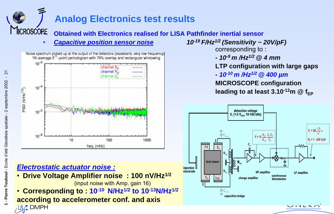
Analog Electronics test results• Obtained with Electronics realised for LISA Pathfinder inertial sensor• Capacitive position sensor noise 10-19 F/Hz1/2 (Sensitivity ~ 20V/pF)
corresponding to :- 10-9 m /Hz1/2 @ 4 mmLTP configuration with large gaps- 10-10 m /Hz1/2 @ 400 µmMICROSCOPE configurationleading to at least 3.10-12m @ fEP
Electrostatic actuator noise :• Drive Voltage Amplifier noise : 100 nV/Hz1/2
(input noise with Amp. gain 16)• Corresponding to : 10-10 N/Hz1/2 to 10-13N/Hz1/2
according to accelerometer conf. and axis
S
S
Npri
CB
CA
CF
Npri
C -CA B
CF
Npri
Nsec
xε0Se2
Cstray
Cstray
l-x
l+x
1 -P
ierr
e To
ubou
l-Ec
ole
d’ét
éG
éodé
sie
spat
iale
-2 s
epte
mbr
e20
02 -
22
1 .10 5 1 .10 4 1 .10 3 0.01 0.1 1 101 .10 13
1 .10 12
1 .10 11
1 .10 10
1 .10 9
requirementinner accelerometer axial resolutionouter accelerometer axial resolution
Hz
m/s
^2/H
z^1/
2
10 9−
3.08365 10 13−×
requirement
resol 0 f k,( )
resol 1 f k,( )
10 100×1 10 5−× f k
fep
Titanium
Platinum
Capacitive sensor
Wire damping
Temp. gradient fluc.
m/s2/Hz1/2
10-12
10-10
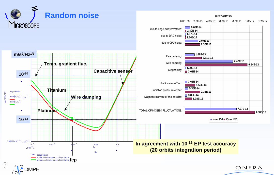
In agreement with 10-15 EP test accuracy(20 orbits integration period)
8.08E-14
1.57E-14
2.07E-13
1.48E-13
7.42E-13
1.39E-14
3.61E-14
5.36E-14
3.85E-14
7.97E-13
2.30E-14
1.34E-14
2.35E-13
2.61E-13
9.64E-13
3.61E-14
1.59E-13
2.36E-13
1.08E-13
1.08E-12
0.0E+00 2.0E-13 4.0E-13 6.0E-13 8.0E-13 1.0E-12 1.2E-12
due to cage dissymmetries:
due to DAC noise:
due to CPD noise:
Gas damping:
Wire damping:
Outgassing:
Radiometer effect:
Radiation pressure effect:
Magnetic moment of the satellite:
TOTAL OF NOISE & FLUCTUATIONS:
m/s^2/Hz^1/2
Inner PM Outer PM
Random noise
1 -P
ierr
e To
ubou
l-Ec
ole
d’ét
éG
éodé
sie
spat
iale
-2 s
epte
mbr
e20
02 -
23
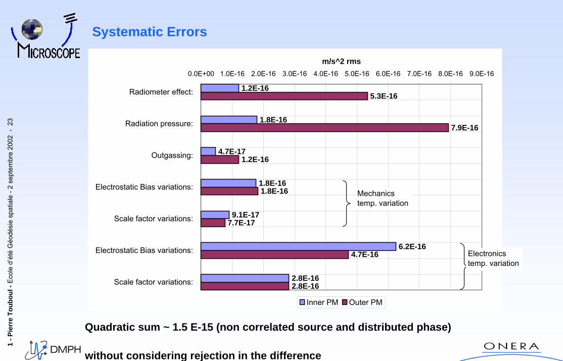
Systematic Errors
Quadratic sum ~ 1.5 E-15 (non correlated source and distributed phase)
without considering rejection in the difference
1.2E-16
1.8E-16
4.7E-17
1.8E-16
9.1E-17
6.2E-16
2.8E-16
5.3E-16
7.9E-16
1.2E-16
1.8E-16
7.7E-17
4.7E-16
2.8E-16
0.0E+00 1.0E-16 2.0E-16 3.0E-16 4.0E-16 5.0E-16 6.0E-16 7.0E-16 8.0E-16 9.0E-16
Radiometer effect:
Radiation pressure:
Outgassing:
Electrostatic Bias variations:
Scale factor variations:
Electrostatic Bias variations:
Scale factor variations:
m/s^2 rms
Inner PM Outer PM
Mechanicstemp. variation
Electronicstemp. variation
1 -P
ierr
e To
ubou
l-Ec
ole
d’ét
éG
éodé
sie
spat
iale
-2 s
epte
mbr
e20
02 -
24
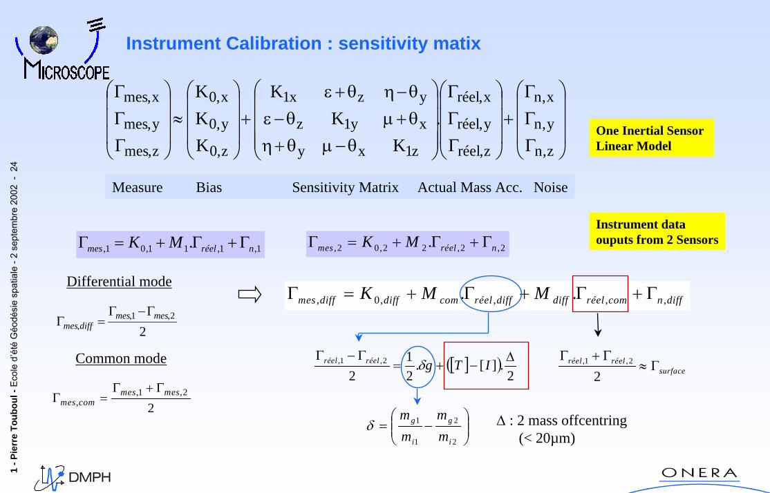
Instrument Calibration : sensitivity matix
⎟⎟⎟
⎠
⎞
⎜⎜⎜
⎝
⎛
ΓΓΓ
+⎟⎟⎟
⎠
⎞
⎜⎜⎜
⎝
⎛
ΓΓΓ
⎟⎟⎟⎟
⎠
⎞
⎜⎜⎜⎜
⎝
⎛
θ−µθ+ηθ+µθ−εθ−ηθ+ε
+⎟⎟⎟
⎠
⎞
⎜⎜⎜
⎝
⎛
≈⎟⎟⎟
⎠
⎞
⎜⎜⎜
⎝
⎛
ΓΓΓ
zn
yn
xn
zréel
yréel
xréel
z1xy
xy1z
yzx1
z0
y0
x0
zmes
ymes
xmes
KK
K
KKK
,
,
,
,
,
,
,
,
,
,
,
,.
One Inertial SensorLinear Model
Measure Bias Sensitivity Matrix Actual Mass Acc. Noise
Instrument dataouputs from 2 Sensors
1,1,11,01, . nréelmes MK Γ+Γ+=Γ 2,2,22,02, . nréelmes MK Γ+Γ+=Γ
Differential modediffncomréeldiffdiffréelcomdiffdiffs MMK ,,,,0, ..
∆ : 2 mass offcentring(< 20µm)
me Γ+Γ+Γ+=
[ ]( )2
.][.21
22,1, ∆
−+=Γ−Γ
ITgréelréel δ surfaceréelréel Γ≈
Γ+Γ2
2,1,
Γ
22,1,
,mesmes
diffmesΓ−Γ
=Γ
⎟⎟⎠
⎞⎜⎜⎝
⎛−=
2
2
1
1
i
g
i
g
mm
mm
δ
Common mode
22,1,
,mesmes
commesΓ+Γ
=Γ
1 -P
ierr
e To
ubou
l-Ec
ole
d’ét
éG
éodé
sie
spat
iale
-2 s
epte
mbr
e20
02 -
25
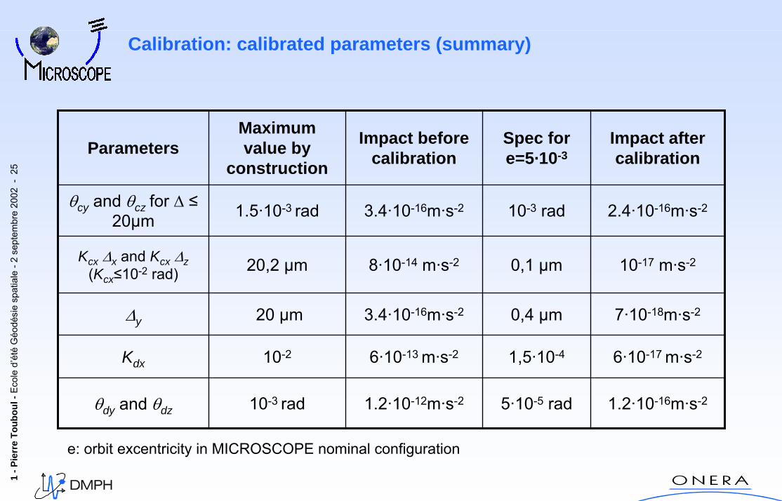
Calibration: calibrated parameters (summary)
5·10-5 rad
1,5·10-4
0,4 µm
0,1 µm
10-3 rad
Spec for e=5·10-3
1.2·10-12m·s-2
6·10-13 m·s-2
3.4·10-16m·s-2
8·10-14 m·s-2
3.4·10-16m·s-2
Impact before calibration
6·10-17 m·s-210-2Kdx
1.2·10-16m·s-210-3 radθdy and θdz
7·10-18m·s-220 µm∆y
10-17 m·s-220,2 µmKcx·∆x and Kcx·∆z(Kcx≤10-2 rad)
2.4·10-16m·s-21.5·10-3 radθcy and θcz for ∆ ≤20µm
Impact after calibration
Maximum value by
constructionParameters
e: orbit excentricity in MICROSCOPE nominal configuration
1 -P
ierr
e To
ubou
l-Ec
ole
d’ét
éG
éodé
sie
spat
iale
-2 s
epte
mbr
e20
02 -
26
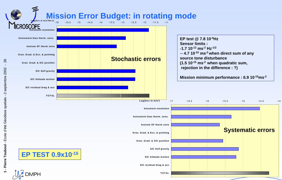
Mission Error Budget: in rotating mode
EP test @ 7.8 10-4HzSensor limits : -1.7 10-12 ms-2 Hz-1/2
-- 4.7 10-15 ms-2 when direct sum of anysource tone disturbance(1.5 10-15 ms-2 when quadratic sum,rejection in the difference : ?)
Mission minimum performance : 6.9 10-15ms-2
EP TEST 0.9x10⁻¹⁵
-16 -15.5 -15 -14.5 -14 -13.5 -13 -12.5 -12 -11.5 -11
Intrument resolution
Instrument bias therm. sens.
Instrum SF therm sens
Grav. Grad. & Ecc. & pointing
Grav. Grad. & S/C position
S/C Self gravity
S/C Attitude motion
S/C residual drag & acc
TOTAL
Log(Acc in m /s²/Hz½ )
-17 -16.5 -16 -15.5 -15 -14.5 -14
Intrument resolution
Instrument bias therm. sens.
Instrum SF therm sens
Grav. Grad. & Ecc. & pointing
Grav. Grad. & S/C position
S/C Self gravity
S/C Attitude motion
S/C residual drag & acc
TOTAL
Log(Acc in m /s²)
Stochastic errors
Systematic errors
1 -P
ierr
e To
ubou
l-Ec
ole
d’ét
éG
éodé
sie
spat
iale
-2 s
epte
mbr
e20
02 -
27
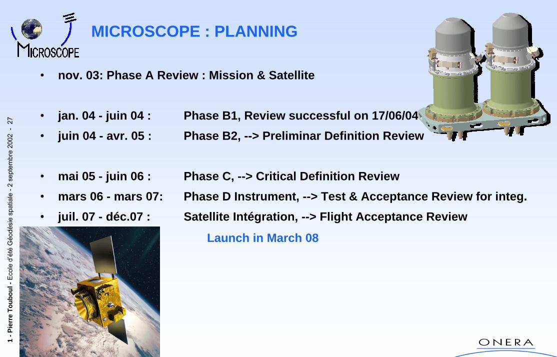
• nov. 03: Phase A Review : Mission & Satellite
• jan. 04 - juin 04 : Phase B1, Review successful on 17/06/04• juin 04 - avr. 05 : Phase B2, --> Preliminar Definition Review
• mai 05 - juin 06 : Phase C, --> Critical Definition Review• mars 06 - mars 07: Phase D Instrument, --> Test & Acceptance Review for integ.• juil. 07 - déc.07 : Satellite Intégration, --> Flight Acceptance Review
Launch in March 08
MICROSCOPE : PLANNING