Embed Size (px)
Citation preview

FR - Notice de fonctionnement GB - User’s manual
MPC 25
pH MÈTRE / CONDUCTIMÈTRE pH METER / CONDUCTIMETER

Français
2 pH mètre / Conductimètre MPC 25
Vous venez d’acquérir un pH mètre / Conductimètre MPC 25 et nous vous remercions de votre confiance. Pour obtenir le meilleur service de votre appareil :
• lisez attentivement cette notice de fonctionnement, • respectez les précautions d’emploi
SIGNIFICATION DES SYMBOLES UTILISÉS
ATTENTION, risque de DANGER ! L’opérateur doit consulter la présente notice à chaque fois que ce symbole de danger est rencontré.
Le marquage CE indique la conformité aux directives européennes, notamment DBT et CEM.
La poubelle barrée signifie que, dans l’Union Européenne, le produit fait l’objet d’une collecte sélective conformément à la directive DEEE 2002/96/EC : ce matériel ne doit pas être traité comme un déchet ménager.

Français
pH mètre / Conductimètre MPC 25 3
SOMMAIRE
1. CARACTÉRISTIQUES TECHNIQUES..................................................................... 4
2. DESCRIPTIF DE L’APPAREIL ................................................................................. 5 2.1 FACE SUPÉRIEURE .................................................................................................... 5 2.2 FACE ARRIÈRE ........................................................................................................... 6 2.3 FACE INFÉRIEURE ..................................................................................................... 6 3. UTILISATION............................................................................................................... 7 3.1 BRANCHEMENT ET MISE EN MARCHE .................................................................. 7 3.2 RÉGLAGE ET MESURE DU PH .................................................................................. 7
3.2.1 CORRECTION MANUELLE DE TEMPÉRATURE ..................................... 7 3.2.2 TARAGE ET RÉGLAGE DE L’ÉCHELLE DE PH : .................................... 7
3.3 MESURE DES POTENTIELS :..................................................................................... 8 4. PRINCIPE DE LA MESURE DE CONDUCTIVITÉ .............................................. 10 4.1 CARACTÉRISTIQUES DE LA CELLULE DE MESURE : ....................................... 10 4.2 ÉTALONNAGE DE LA CHAÎNE DE MESURE : ...................................................... 11 4.3 DÉTERMINATION DU COEFFICIENT DE CELLULE :.......................................... 11 4.4 RÉGLAGE ET MESURE DE LA CONDUCTIVITÉ .................................................. 11 4.5 TABLEAU : CONDUCTIVITÉ DES SOLUTIONS DE CHLORURE DE
POTASSIUM .............................................................................................................. 12 4.5.1 VARIATION DE LA CONDUCTIVITÉ EN FONCTION DE LA
TEMPÉRATURE....................................................................................... 12 4.5.2 CONDUCTIVITÉ À 20°C DES SOLUTIONS ÉTALONS DE CHLORURE
DE POTASSIUM ...................................................................................... 13 5. SORTIE ENREGISTREUR ....................................................................................... 13
6. DIFFÉRENTES ANOMALIES POSSIBLES ........................................................... 14
7. RÈGLES DE SÉCURITÉ ........................................................................................... 15
8. MAINTENANCE ......................................................................................................... 16 8.1 NETTOYAGE ............................................................................................................. 16 8.2 VÉRIFICATION MÉTROLOGIQUE ......................................................................... 16 8.3 RÉPARATIONS .......................................................................................................... 16 9. POUR COMMANDER ............................................................................................... 17 9.1 ÉTAT DE LIVRAISON ............................................................................................... 17

Français
4 pH mètre / Conductimètre MPC 25
1. CARACTÉRISTIQUES TECHNIQUES
Affichage à cristaux liquides 2000 points
Gammes : pH mV Conductivité
0,00 à 14,00 pH -1999 à + 1999mV 0-200mS/cm, 0-20mS/cm, 0-2000µS/cm, 0-200µS/cm
Tension aux bornes de la cellule de conductivité
100mV / 680Hz
Précision ± 1%
Compensation manuelle de température (pour le pH)
0 à 100°C
Température d’utilisation 0 à 50°C
Altitude limite 2000m
Humidité 5 à 80% à 35°C
Classe de pollution Catégorie 2
Catégorie d’utilisation 2
CONFORMITÉ AUX NORMES :
Sécurité Avec l’alimentation livrée : NF EN 61010-1 Conditions d’environnement normales (utilisation en intérieur)
CEM NF EN 61326 appareil de classe B, fonctionnement discontinu.
Consommation 0,5W
Dimensions 275 x 208 x 51 mm
Poids 800g Le MPC 25 est fourni avec un bloc d’alimentation. Alimentation 230V – 50/60Hz
Sortie 9V

Français
pH mètre / Conductimètre MPC 25 5
2. DESCRIPTIF DE L’APPAREIL
2.1 FACE SUPÉRIEURE 1. Afficheurs à cristaux liquides 2. Bouton de réglage de la température 3. Bouton de réglage de l’échelle 4. Bouton de réglage du coefficient de cellule 5. Bouton de réglage du tarage 6. Bouton de commutation pH/mV 7. Commutateur de gamme à 4 positions

Français
6 pH mètre / Conductimètre MPC 25
2.2 FACE ARRIÈRE
1. Noire - Borne 4mm isolée pour sortie enregistreur conductivité
2. Rouge - Borne 4mm isolée pour sortie enregistreur conductivité
3. Noire - Borne 4mm isolée pour sortie enregistreur pH/mV
4. Rouge - Borne 4mm isolée pour sortie enregistreur pH/mV 5. Prise du bloc d’alimentation 6. Fiche BNC pour cellule de conductivité 7. Fiche BNC pour électrode pH/mV 8. Entrée pour électrode de référence séparée
2.3 FACE INFÉRIEURE Étiquette d’identification.
Français
pH mètre / Conductimètre MPC 25 7
3. UTILISATION
3.1 BRANCHEMENT ET MISE EN MARCHE Déballer l’appareil, le bloc d’alimentation, les solutions et le manuel d’utilisation. Mesure pH/mV : Brancher l’éléctrode combinée de pH ou une autre électrode combinée sur la fiche « Electrode », fiche BNC située à l’arrière de l’appareil. Pour les électrodes séparées, connecter l’électrode de verre ou métallique sur la fiche « Electrode », et l’électrode de référence sur la borne jaune. Mesure de la conductivité : Connecter la cellule de conductivité sur la fiche « Conductivity cell », fiche BNC à l’arrière de l’appareil. Enfin brancher le bloc d’alimentation dans la prise « Power ». (Le MPC 25 doit être utilisé uniquement avec le bloc d’alimentation fourni).
3.2 RÉGLAGE ET MESURE DU pH A l’aide du commutateur, se placer sur la position pH.
3.2.1 CORRECTION MANUELLE DE TEMPERATURE Relever la température de l’échantillon à analyser. Amener le repère du bouton « Temperature » à la température du milieu à analyser ou de la solution tampon. Remarque : Idéalement, les solutions tampons utilisées pour l’étalonnage de la chaîne de mesure (pH mètre-électrode) doivent être à cette température.
3.2.2 TARAGE ET REGLAGE DE L’ECHELLE DE pH :
3.2.2.1 Vérifications / précautions concernant les électrodes : Avant chaque opération de mesure de pH s’assurer que :
la boule de verre de l’électrode ne contient pas de bulle d’air, l’électrode de référence à électrolyte liquide est correctement remplie
avec une solution de chlorure de potassium de concentration adéquate (KCI 1 mol.L-1),
le bouchon de l’orifice de remplissage de l’électrode de référence est ouvert,
les électrodes sont bien branchées.

Français
8 pH mètre / Conductimètre MPC 25
3.2.2.2 Étalonnage Exemple : Utilisation de solutions tampon pH4.00 et pH7.00.
Rincer l’électrode combinée pH (ou les deux électrodes séparées) à l’eau distillée.
Plonger l’électrode dans la solution tampon de pH7.00 (toujours en premier).
Lorsque le signal est stabilisé, à l’aide du bouton « Offset » amener la valeur affichée à 7.00
Rincer l’électrode à l’eau distillée. Plonger l’électrode dans une solution tampon pH4.00. Lorsque le signal est stabilisé, à l’aide du bouton « Slope » amener la
valeur à 4.00 Rincer l’électrode à l’eau distillée. Plonger l’électrode dans le milieu à analyser.
3.3 MESURE DES POTENTIELS : A l’aide du commutateur se placer sur la position mV. Exemple : Utilisation de la solution Michaëlis. Composition de la solution : KCI K3 [Fe(CN)6] K4 [Fe(CN)6] ATTENTION : ne pas acidifier. Couple électrochimique en jeu : [Fe(CN)6]3- + 1ē [Fe(CN)6]4- Le potentiel d’oxydo-réduction E d’une solution est égal au potentiel lu (E lu) augmenté du potentiel de l’électrode de référence (E réf). Pour une électrode de référence (Ag, AgCI, KCI 1 mol.L-1) E réf = 236mV à 25°C (Cf. tableau p 9). Pour une solution étalon Michaëlis E = 382mV. Donc E lu = 382 – 236 = 146mV.
Rincer à l’eau distillée l’électrode combinée ou les électrodes séparées (par exemple : une électrode de platine et une électrode de référence).
Plonger l’électrode dans la solution de Michaëlis. A l’aide du bouton « Offset » amener si nécessaire l’affichage à + 146. Rincer l’électrode à l’eau distillée. Plonger l’électrode dans le milieu à analyser.
Si l’on travaille à une température autre que 25°C ou avec une électrode de référence autre que (Ag, AgCl, KCl 1 mol.L-1) le potentiel E lu sera différent de celui indiqué sur l’étiquette. Voici le tableau applicable à la solution Michaëlis :

Français
pH mètre / Conductimètre MPC 25 9
DIFFÉRENCE DE POTENTIEL ENTRE L’ÉLECTRODE DE PLATINE ET L’ÉLECTRODE DE RÉFÉRENCE PLONGÉES DANS LA SOLUTION DE MICHAËLIS DILUÉE (voir étiquette)
Électrode de référence
Température
(Ag, AgCI, KCI, 1mol.L-1)
(Ag, AgCI, KCI, 3mol.L-1)
(Ag, AgCI, KCI, 3,5mol.L-1)
(Ag, AgCI, KCI, saturé)
(Hg, Hg2, CI2 KCI 1mol.L-1)
(Hg, Hg2, CI2 KCI saturé)
(Hg, Hg2, SO4 K2 SO4 1mol.L-1)
15°C 164mV 192mV 195mV 198mV 121mV 156mV
20°C 155mV 183mV 187mV 191mV 111mV 147mV
25°C 146mV 174mV 177mV 183mV 99mV 138mV -276mV
30°C 135mV 165mV 168mV 175mV 87mV 128mV
INCERTITUDE ± 4mV ± 4mV ± 4mV ± 4mV ± 4mV ± 4mV ± 4mV

Français
10 pH mètre / Conductimètre MPC 25
4. PRINCIPE DE LA MESURE DE CONDUCTIVITÉ
La conductance électrique G d’un liquide dépend de la géométrie du volume de liquide considéré. C’est l’inverse de la résistance R. Elle s’exprime en Siemens (S).
G = 1 / R ; 1 S = 1 Ω-1
La conductivité γ est l’inverse de la résistivité ρ. Elle s’exprime en Siemens par
centimètre. La conductivité γ est une caractéristique spécifique d’un liquide. C’est la conductivité d’une colonne de liquide d’une section de 1cm2 et d’une longueur de 1cm. La conductivité d’un électrolyte ne dépend que de sa nature et de sa concentration.
γ = 1 / ρ ; 1 S.cm-1 = 1 (Ω.cm)-1 De même que la résistance et la résistivité sont reliées par la formule : R = ρ (I/S)
La conductance et la conductivité sont reliées par la formule : G = γ (S / I) Avec G conductance en Siemens
γ conductivité en S.cm-1. S surface en cm2. I longueur en cm.
Pour mesurer la conductivité d’un électrolyte, il suffit de maintenir une tension alternative fixe aux bornes de la cellule et de mesurer le courant qui la traverse.
4.1 CARACTÉRISTIQUES DE LA CELLULE DE MESURE : La cellule de conductimétrie est constituée de deux plaques carrées (5mm de côté) de platine platiné, planes parallèles et distantes de 4mm. Les plaques de platine lisses sont platinées. C’est-à-dire recouverte de dendrites de platine formant ainsi une surface développée poreuse. Cette opération a pour objectif de limiter les phénomènes de polarisation des électrodes. La valeur de conductance mesurée pour une solution électrolytique dépend non seulement de la conductivité du strict volume de solution compris entre les plaques du capteur mais également de la solution présente à proximité de ce volume cubique puisque la cellule de mesure est immergée dans un volume de solution plus important.

Français
pH mètre / Conductimètre MPC 25 11
4.2 ÉTALONNAGE DE LA CHAÎNE DE MESURE : Dans la pratique, la « constante de cellule » de la chaîne de mesure ne peut être obtenue que par étalonnage en plongeant la cellule utilisée dans une solution étalon de conductivité connue à une température donnée (par exemple : solution aqueuse de chlorure de potassium décimolaire). Le capteur fourni ayant une constante de cellule voisine de l’unité, un léger réglage au moyen du bouton de coefficient de cellule permet d’ajuster la valeur de conductance, initialement obtenue, à la valeur réelle de conductivité de la solution étalon (voir tables de conductivité en fonction de la température). La chaîne de mesure est alors étalonnée et donne directement la valeur de conductivité du milieu étudié.
4.3 DÉTERMINATION DU COEFFICIENT DE CELLULE : Si toutefois l’utilisateur souhaite obtenir la valeur réelle de la constante de cellule d’une sonde isolée, il est alors nécessaire d’utiliser une résistance pure. Dans un premier temps, on effectue le réglage du conductimètre connecté à cette résistance pure. Ensuite, la sonde, connectée au même appareil réglé, est plongée dans la solution étalon. La constante de cellule réelle de cette sonde est alors obtenue par le calcul du rapport de la valeur de conductance affichée sur la valeur de conductivité connue de cette solution étalon mesurée.
Gaffichée / γétalon = Constante de cellule réelle
4.4 RÉGLAGE ET MESURE DE LA CONDUCTIVITÉ Il est conseillé d’effectuer le réglage de la cellule avec une solution étalon de la même gamme que celle de la solution à mesurer. Exemple : Solution de KCI 0,1mol.L-1 Positionner le commutateur de gamme sur la position : 20mS. Tremper la cellule dans la solution KCI 0,1mol.L-1. A l’aide du bouton « Cell coeff. » amener l’affichage à la valeur donnée par le tableau ci-joint en fonction de la température de la solution. (exemple : 12.97mS à 25°C) Rincer la cellule dans de l’eau distillée. Plonger la cellule dans le milieu à analyser.

Français
12 pH mètre / Conductimètre MPC 25
4.5 TABLEAU : CONDUCTIVITÉ DES SOLUTIONS DE CHLORURE DE POTASSIUM
4.5.1 VARIATION DE LA CONDUCTIVITÉ EN FONCTION DE LA TEMPÉRATURE
Dilution
au 10ème Dilution au 50ème
Dilution au 100ème
Dilution au 1000ème
KCl 0,1 mol.L-1 KCl 0,02 mol.L-1 KCl 0,01 mol.L-1 KCl 0,001 mol.L-1 TEMPERATURE °C Conductivité Conductivité Conductivité Conductivité mS/cm mS/cm µS/cm µS/cm
15 10,410 2,242 1 147 119,1 16 10,670 2,293 1 174 121,9 17 10,930 2,347 1 199 124,5 18 11,190 2,398 1 224 127,1 19 11,430 2,451 1 250 129,6 20 11,700 2,500 1 279 132,5 21 11,960 2,551 1 305 135,3 22 12,220 2,604 1 331 138,1 23 12,470 2,659 1 359 140,9 24 12,730 2,710 1 387 143,8 25 12,970 2,769 1 412 146,5

Français
pH mètre / Conductimètre MPC 25 13
4.5.2 CONDUCTIVITÉ À 20°C DES SOLUTIONS ÉTALONS DE CHLORURE DE POTASSIUM
Concentration (mol.L-1) Dilution Conductivité
mS/cm
1 Chlorure de potassium ………… 74.56g Eau distillée .....……….. q.s.p. 1 000 mL 112,359
Volume de solution Eau distillée 1 mol.L-1 (mL) (mL)
0,400 40 q.s.p. 100 41,660 0,200 20 100 22,070 0,150 15 100 16,390 0,100 10 100 11,700 0,067 6,6 100 7,812 0,050 5 100 5,988 0,040 4 100 4,807 0,033 3,3 100 4,032 0,025 2,5 100 3,048
Volume de solution 0,1 mol. L-1 (mL)
Eau distillée (mL)
Conductivité µS/cm
0,020 20 q.s.p. 100 2 510 0,015 15 100 1 851 0,010 10 100 1 279 0,008 8 100 1 000 0,0067 6,6 100 843,8 0,005 5 100 653,5 0,004 4 100 512,8 0,0033 3,3 100 430,1 0,0025 2,5 100 325,2 0,002 2 100 298,5 0,0015 1,5 100 196 0,001 1 100 132,5
Nota : Prendre toutes les précautions indispensables pour obtenir des mesures exactes et des solutions homogènes.
5. SORTIE ENREGISTREUR
Les sorties enregistreurs se trouvent sur la face arrière de l’appareil.
Bornes noires et rouges pour fiche banane 4mm isolée. En conductivité : Affichage : 0 - 2000 (quelque soit la gamme)
Sortie enregistreur : 0-5000 mV (0-5V)
En pH : 0-14pH Sortie enregistreur : 0-5000mV (0-5V) En mV : -2000 / +2000mV Sortie enregistreur : 0-5000mV (0-5V)
Français
14 pH mètre / Conductimètre MPC 25
6. DIFFÉRENTES ANOMALIES POSSIBLES
ANOMALIES CONSEILS
Pas d’affichage Vérifier l’alimentation 230 V.
Vérifier le branchement du bloc d’alimentation dans la prise d’alimentation « Power ».
Pas de stabilisation du pH quelque soit la solution mesurée.
Vérifier que l’électrode de pH est correctement immergée (pont d’écoulement, boule de verre).
Vérifier le branchement de cette électrode.
Lors de l’étalonnage dans la solution tampon pH7.00, impossibilité d’amener l’affichage à la valeur 7.00
Potentiomètre « Offset » en butée.
Vérifier le niveau de l’électrolyte de référence.
Changer l’électrolyte de l’électrode de référence kCl 1 mol.L-1 (si électrolyte liquide).
Lors de l’étalonnage dans la solution tampon pH4.00 ou pH9.00, impossibilité d’amener l’affichage aux valeurs 4.00 et 9.00 respectivement.
Potentiomètre « Slope » en butée.
Vérifier la position du potentiomètre de température.
Nettoyer l’électrode en la plongeant quelques heures dans une solution diluée d’acide chlorhydrique HCl (0,1 mol.L-1).
Pas de stabilisation de la conductivité quelque soit la solution mesurée.
Aucune variation de la conductivité quelque soit la solution mesurée.
Vérifier si la cellule de conductivité est correctement immergée.
Vérifier le branchement de cette cellule.
L’appareil va en saturation.
(l’afficheur indique 1)
Vous êtes en dépassement de gamme.
Placez le commutateur de gamme sur la gamme supérieure.
Dans solution étalon potentiomètre de réglage cellule en butée.
Nettoyer la cellule
Français
pH mètre / Conductimètre MPC 25 15
7. RÈGLES DE SÉCURITÉ
L’alimentation secteur doit respecter les caractéristiques : 230 V ± 10%
50-60 Hz - 5W.
L’intérieur de l’appareil doit toujours être maintenu propre et sec.
Si l’appareil est utilisé d’une façon qui n’est pas conforme aux spécifications, la protection assurée par l’appareil peut être compromise.
Débrancher l’appareil avant toute ouverture du boîtier.
Le bloc d’alimentation tient lieu de sectionneur de tension.
Le pH-mètre conductimètre MPC25 est destiné à des personnes
connaissant les bonnes pratiques de laboratoire. Si le MPC25 n’est pas utilisé conformément à ces instructions d’utilisation, la protection offerte par le matériel peut être réduite.
Le fonctionnement de l’appareil peut présenter des perturbations de
fonctionnement sous l’effet de champs électriques rayonnés ou d’émissions conduites.
L’appareil ne doit pas êre utilisé dans le cadre d’un fonctionnement
permanent sans contrôle humain. Cet appareil produit, utilise et peut émettre une énergie sous forme de
radio fréquence et s’il n’est pas installé et utilisé conformément à la notice d’utilisation, il peut causer des interférences avec les communications radio.
Dans une zone résidentielle, l’utilisateur de ce matériel causera
probablement des interférences ; auquel cas, l’utilisateur devra à ses propres frais, prendre toutes les mesures requises pour remédier à l’interférence.
Français
16 pH mètre / Conductimètre MPC 25
8. MAINTENANCE
L’instrument ne comporte aucune pièce susceptible d’être remplacée par un personnel non formé et non agréé. Toute intervention non agréée ou tout remplacement de pièce par des équivalences risque de compromettre gravement la sécurité.
8.1 NETTOYAGE Utilisez un chiffon humidifié avec de l’eau propre ou avec un détergent neutre pour essuyer l’émetteur, et utilisez ensuite un chiffon sec pour l’essuyer de nouveau. N’utilisez de nouveau l’appareil que lorsqu’il est complètement sec.
8.2 VÉRIFICATION MÉTROLOGIQUE Comme tous les appareils de mesure ou d’essais, une vérification périodique est nécessaire. Nous vous conseillons une vérification annuelle de cet appareil. Pour les vérifications et étalonnages, adressez- vous à nos laboratoires de métrologie accrédités (renseignements et coordonnées sur demande) ou à l’agence de votre pays.
8.3 RÉPARATIONS Pour les réparations sous garantie et hors garantie, contactez votre agence commerciale Chauvin Arnoux la plus proche ou votre centre technique régional Manumesure qui établira un dossier de retour et vous communiquera la procédure à suivre. Coordonnées disponibles sur notre site : http://www.chauvin-arnoux.com ou par téléphone aux numéros suivants : 02 31 64 51 55 (centre technique Manumesure), 01 44 85 44 85 (Chauvin Arnoux). Pour les réparations hors de France métropolitaine, sous garantie et hors garantie, retournez l’appareil à votre agence Chauvin Arnoux locale ou à votre distributeur.

Français
pH mètre / Conductimètre MPC 25 17
9. POUR COMMANDER
9.1 ÉTAT DE LIVRAISON • 1 pH mètre / Conductimètre MPC 25 • 1 notice de fonctionnement • 2 solutions tampon pH • 1 solution KCI 1Mol/l de 125ml • 1 solution Michaëlis • 1 Alimentation 9V • 1 Adaptateur 2mm/4mm Le tout conditionné dans une boîte en carton.

English
18 pH METER / Conductimeter MPC 25
You have just puchased a MPC 25 pH meter / Conductimeter, and we thank you. For best results with your device:
• Read these operating instructions carefully, • Observe the precautions of use.
MEANINGS OF THE SYMBOLS USED
WARNING, risk of DANGER! The operator must refer to this user’s manual whenever this danger symbol appears.
The CE marking indicates conformity with European directives, in particular LVD and EMC.
The rubbish bin with a line through it indicates that, in the European Union, the product must undergo selective disposal in compliance with Directive WEEE 2002/96/EC. This equipment must not be treated as household waste.

English
pH METER / Conductimeter MPC 25 19
CONTENTS
1. TECHNICAL SPECIFICATIONS ............................................................................ 20
2. DESCRIPTION OF THE INSTRUMENT ................................................................ 21 2.1 TOP .............................................................................................................................. 21 2.2 REAR PANEL ............................................................................................................. 22 2.3 BOTTOM .................................................................................................................... 22 3. USE ............................................................................................................................... 23 3.1 CONNECTION AND STARTING UP ........................................................................ 23 3.2 ADJUSTMENT AND MEASUREMENT OF THE PH ............................................... 23
3.2.1 MANUAL TEMPERATURE CORRECTION .............................................. 23 3.2.2 CALIBRATION AND ADJUSTMENT OF THE PH SCALE: ..................... 23
3.3 MEASUREMENT OF POTENTIALS: ....................................................................... 24 4. PRINCIPLE OF THE CONDUCTIVITY MEASUREMENT ................................ 26 4.1 CHARACTERISTICS OF THE MEASUREMENT CELL: ........................................ 26 4.2 CALIBRATING THE MEASUREMENT SYSTEM: .................................................. 27 4.3 DETERMINING THE CELL COEFFICIENT:............................................................ 27 4.4 ADJUSTMENT AND MEASUREMENT OF THE CONDUCTIVITY ...................... 27 4.5 TABLE: CONDUCTIVITY OF POTASSIUM CHLORIDE SOLUTIONS ................ 28
4.5.1 CONDUCTIVITY VS. TEMPERATURE .................................................... 28 4.5.2 CONDUCTIVITY OF REFERENCE SOLUTIONS OF POTASSIUM
CHLORIDE AT 20°C ................................................................................ 29 5. RECORDER OUTPUT ............................................................................................... 29
6. VARIOUS POSSIBLE PROBLEMS ......................................................................... 30
7. SAFETY RULES ......................................................................................................... 31
8. MAINTENANCE ......................................................................................................... 32 8.1 CLEANING ................................................................................................................. 32 8.2 METROLOGICAL CHECK ........................................................................................ 32 8.3 REPAIRS ..................................................................................................................... 32 9. TO ORDER .................................................................................................................. 33 9.1 DELIVERY CONDITION ........................................................................................... 33

English
20 pH METER / Conductimeter MPC 25
1. TECHNICAL SPECIFICATIONS
2000-point liquid crystal display
Ranges: pH mV Conductivity
0,00 to 14,00 pH -1999 to + 1999mV 0-200mS/cm, 0-20mS/cm, 0-2000µS/cm, 0-200µS/cm
Voltage across the terminals of the conductivity cell.
100mV / 680Hz
Accuracy ± 1%
Manual temperature compensation ( for the pH)
0 to 100°C
Temperature of use 0 to 50°C
Maximum altitude 2000m
Humidity 5 to 80% at 35°C
Pollution class Category 2
Category of use 2
COMPLIANCE WITH STANDARDS:
Safety With the power supply provided: EN 61010-1. Normal environmental conditions (indoor use)
CEM EN 61326, class B instrument, intermittent operation.
Consumption 0,5W
Dimensions 275 x 208 x 51 mm
Weight 800g The MPC 25 is provided with a power supply unit. Power supply 230V – 50/60Hz
Output 9V

English
pH METER / Conductimeter MPC 25 21
2. DESCRIPTION OF THE INSTRUMENT
2.1 TOP 1. Liquid crystal display units 2. Temperature adjustment knob 3. Scale adjustment knob 4. Cell coefficient adjusment knob 5. Calibration adjustment knob 6. pH/mV switch 7. 4-position range switch

English
22 pH METER / Conductimeter MPC 25
2.2 REAR PANEL
1. Black - Insulated 4mm terminal for conductivity recorder output
2. Red - Insulated 4mm terminal for conductivity recorder output
3. Black - Insulated 4mm terminal for pH/mV recorder output
4. Red - Insulated 4mm terminal for pH/mV recorder output 5. Connector for the power supply unit 6. BNC connector for conductivity cell 7. BNC connector for pH/mV electrode 8. Input for separate reference electrode
2.3 BOTTOM Identification label.

English
pH METER / Conductimeter MPC 25 23
3. USE
3.1 CONNECTION AND STARTING UP Unpack the instrument, the power supply unit, the solutions, and the operating manual. pH/mV measurement: Connect the combined pH electrode or another combined electrode to the "Electrode" connector (BNC connector on the back of the instrument). With the separate electrodes, connect the glass or metal electrode to the "Electrode" jack and the reference electrode to the yellow terminal. Conductivity measurement: Connect the conductivity cell to the "Conductivity cell" connector (BNC connector on the back of the instrument). Finally, connect the power supply unit to the "Power" connector. (The MPC 25 must be used only with the power supply unit provided).
3.2 ADJUSTMENT AND MEASUREMENT OF THE pH Set the switch to pH.
3.2.1 MANUAL TEMPERATURE CORRECTION Note the temperature of the sample to be analyzed. Set the mark on the "Temperature" knob to the temperature of the medium to be analyzed or of the buffer solution. Remark: Ideally, the buffer solutions used to calibrate the measurement system (pH meter-electrode) should be at this same temperature.
3.2.2 CALIBRATION AND ADJUSTMENT OF THE pH SCALE:
3.2.2.1 Checks/precautions concerning the electrodes: Before each pH measurement operation, make sure that:
the glass bulb of the electrode does not contain any air bubble, the liquid electrolyte reference electrode is correctly filled with a
potassium chloride solution of the right concentration (KCl, 1 mol.L-1), the plug of the filling orifice of the reference electrode is open, the electrodes are correctly connected.

English
24 pH METER / Conductimeter MPC 25
3.2.2.2 Calibration Example: Use of pH4 and pH7 buffer solutions.
Rinse the combined pH electrode (or the two separate electrodes) in distilled water.
Immerse the electrode in the pH7 buffer solution (always first). When the signal stabilizes, use the "Offset" knob to adjust the value
displayed to 7.00 Rinse the electrode in distilled water. Immerse the electrode in a pH4 buffer solution. When the signal stabilizes, use the "Slope" knob to adjust the reading to
4.00 Rinse the electrode in distilled water. Immerse the electrode in the medium to be analyzed.
3.3 MEASUREMENT OF POTENTIALS: Set the switch to mV. Example: Use of the Michaelis solution. Composition of the solution: KCI K3 [Fe(CN)6] K4 [Fe(CN)6] ATTENTION: do not acidify. Electrochemical couple involved: [Fe(CN)6]3- + 1ē [Fe(CN)6]4- The oxidation-reduction potential E of a solution is equal to the potential read (E read) plus the potential of the reference electrode (E ref). For a reference electrode (Ag, AgCI, KCI 1 mol.L-1) E ref = 236mV at 25°C (Cf. table on p 9). For Michaelis reference solution, E = 382mV. Therefore E read = 382 – 236 = 146mV.
Rinse the combined electrode or the separate electrodes (for example: a platinum electrode and a reference electrode) in distilled water.
Immerse the electrode in the Michaelis solution. Use the "Offset" knob to adjust the display to +146 if necessary. Rinse the electrode in distilled water. Immerse the electrode in the medium to be analyzed.
If the work is done at a temperature other than 25°C or with a reference electrode other than (Ag, AgCl, 1 mol.L-1 KCl), the potential E read will be different from that indicated on the label. Here is the table applicable to the Michaelis solution:

English
pH METER / Conductimeter MPC 25 25
POTENTIAL DIFFERENCE BETWEEN THE PLATINUM ELECTRODE AND THE REFERENCE ELECTRODE IMMERSED IN THE DILUTED MICHAELIS SOLUTION (see label)
Reference electrode
Temperature
(Ag, AgCI, KCI, 1mol.L-1)
(Ag, AgCI, KCI, 3mol.L-1)
(Ag, AgCI, KCI, 3,5mol.L-1)
(Ag, AgCI, KCI, full)
(Hg, Hg2, CI2 KCI 1mol.L-1)
(Hg, Hg2, CI2 KCI full)
(Hg, Hg2, SO4 K2 SO4 1mol.L-1)
15°C 164mV 192mV 195mV 198mV 121mV 156mV
20°C 155mV 183mV 187mV 191mV 111mV 147mV
25°C 146mV 174mV 177mV 183mV 99mV 138mV -276mV
30°C 135mV 165mV 168mV 175mV 87mV 128mV
UNCERTAINTY ± 4mV ± 4mV ± 4mV ± 4mV ± 4mV ± 4mV ± 4mV

English
26 pH METER / Conductimeter MPC 25
4. PRINCIPLE OF THE CONDUCTIVITY MEASUREMENT
The electrical conductance, G, of a liquid depends on the geometry of the volume of liquid involved. It is the reciprocal of the resistance, R. It is expressed in Siemens (S).
G = 1 / R ; 1 S = 1 Ω-1
The conductivity γ is reciprocal of the resistivity ρ. It is expressed in Siemens per
centimetre. The conductivity γ is a specific characteristic of a liquid. It is the conductivity of a column of liquid 1cm long having a cross-sectional area of 1cm2. The conductivity of an electrolyte depends only on its nature and its concentration.
γ = 1 / ρ ; 1 S.cm-1 = 1 (Ω.cm)-1 Just as the resistance and the resistivity are related by the formula: R = ρ (I/S)
The conductance and the conductivity are related by the formula: G = γ (S / I) Where G conductance in Siemens
γ conductivity in S.cm-1. S area in cm2. I length in cm.
The conductivity of an electrolyte can be measured simply by maintaining a fixed alternating voltage on the terminals of the cell and measuring the current that flows through it.
4.1 CHARACTERISTICS OF THE MEASUREMENT CELL: The conductometry cell comprises two square plates (5mm on a side) of platinum-plated platinum, plane, parallel, and 4mm apart. The smooth platinum plates are platinum-plated, in other words covered with platinum dendrites to form a large porous surface area. The purpose of this operation is to limit polarization of the electrodes. The measured conductance of an electrolytic solution depends not only on the conductivity of the volume of solution exactly between the plates of the sensor, but also on the solution near this cubic volume, because the measurement cell is immersed in a larger volume of solution.
English
pH METER / Conductimeter MPC 25 27
4.2 CALIBRATING THE MEASUREMENT SYSTEM: In practice, the "cell constant" of the measurement line can be determined only by calibration, by immersing the cell used in a standard solution having a known conductivity at a given temperature (for example: decimolar aqueous solution of potassium chloride). Since the sensor provided has a cell constant close to unity, a small adjustment using the cell coefficient knob is sufficient to adjust the initial conductance reading to the true conductivity of the reference solution (see tables of conductivity vs. temperature). The measurement system is then calibrated and gives a direct reading of the conductivity of the medium studied.
4.3 DETERMINING THE CELL COEFFICIENT: However, if the user wants to determine the true cell constant of an insulated probe, a pure resistance must be used. First, the conductimeter connected to this pure resistance is adjusted. Then, the probe, connected to the same adjusted instrument, is immersed in the reference solution. The true cell constant of the probe is then found by calculating the ratio of the conductance displayed to the known (measured) conductivity of this reference solution.
Gdisplayed / γreference = True cell constant
4.4 ADJUSTMENT AND MEASUREMENT OF THE CONDUCTIVITY We recommend adjusting the cell using a reference solution in the same range as the solution to be measured. Example : 0.1mol.L-1 solution of KCI Set the range switch to: 20mS. Immerse the cell in the 0.1mol.L-1 KCI solution Use the "Cell coefficient" knob to adjust the display to the value given by the table below as a function of the temperature of the solution. (example : 12.97mS to 25°C) Rinse the cell in distilled water. Immerse the cell in the medium to be analyzed.

English
28 pH METER / Conductimeter MPC 25
4.5 TABLE: CONDUCTIVITY OF POTASSIUM CHLORIDE SOLUTIONS
4.5.1 CONDUCTIVITY VS. TEMPERATURE
Dilution to 1/10
Dilution to 1/50
Dilution to 1/100
Dilution to 1/1000
KCl 0.1 mol.L-1 KCl 0.02 mol.L-1 KCl 0.01 mol.L-1 KCl 0.001 mol.L-1 TEMPERATURE °C Conductivity Conductivity Conductivity Conductivity mS/cm mS/cm µS/cm µS/cm
15 10.410 2.242 1,147 119.1 16 10.670 2.293 1,174 121.9 17 10.930 2.347 1,199 124.5 18 11.190 2.398 1,224 127.1 19 11.430 2.451 1,250 129.6 20 11.700 2.500 1,279 132.5 21 11.960 2.551 1,305 135.3 22 12.220 2.604 1,331 138.1 23 12.470 2.659 1,359 140.9 24 12.730 2.710 1,387 143.8 25 12.970 2.769 1,412 146.5
English
pH METER / Conductimeter MPC 25 29
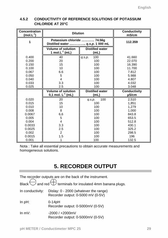
4.5.2 CONDUCTIVITY OF REFERENCE SOLUTIONS OF POTASSIUM CHLORIDE AT 20°C
Concentration (mol.L-1) Dilution Conductivity
mS/cm
1 Potassium chloride ………… 74.56g Distilled water .....……….. q.s.p. 1 000 mL 112.359
Volume of solution Distilled water 1 mol.L-1 (mL) (mL)
0.400 40 q.s.p. 100 41.660 0.200 20 100 22.070 0.150 15 100 16.390 0.100 10 100 11.700 0.067 6.6 100 7.812 0.050 5 100 5.988 0.040 4 100 4.807 0.033 3.3 100 4.032 0.025 2.5 100 3.048
Volume of solution 0,1 mol. L-1 (mL)
Distilled water (mL)
Conductivity µS/cm
0.020 20 q.s.p. 100 2,510 0.015 15 100 1,851 0.010 10 100 1,279 0.008 8 100 1,000 0.0067 6,6 100 843.8 0.005 5 100 653.5 0.004 4 100 512.8 0.0033 3.3 100 430.1 0.0025 2.5 100 325.2 0.002 2 100 298.5 0.0015 1.5 100 196 0.001 1 100 132.5
Nota : Take all essential precautions to obtain accurate measurements and homogeneous solutions.
5. RECORDER OUTPUT
The recorder outputs are on the back of the instrument.
Black and red terminals for insulated 4mm banana plugs. In conductivity: Dislay: 0 - 2000 (whatever the range)
Recorder output: 0-5000 mV (0-5V)
In pH: 0-14pH Recorder output: 0-5000mV (0-5V) In mV: -2000 / +2000mV Recorder output: 0-5000mV (0-5V)

English
30 pH METER / Conductimeter MPC 25
6. VARIOUS POSSIBLE PROBLEMS
PROBLEM ADVICE
No display Check the 230V supply.
Check the connection of the power supply unit to the power connector.
The pH fails to stabilize in all solutions measured.
Check that the pH electrode is correctly immersed (reference jonction, glass bulb).
Check the connection of this electrode.
During calibration in the pH7 buffer solution, impossible to adjust the display to 7.00
Offset potentiometer at stop.
Check the level of the reference electrolyte.
Replace the electrolyte of the 1 mol.L-1 kCl reference electrode (if liquid electrolyte).
During calibration in the pH4 or pH9 buffer solution, impossible to adjust the display to 4.00 and 9.00, respectively.
Slope potentiometer at stop.
Check the position of the temperature potentiometer.
Clean the electrode by dipping it a few times in a dilute hydrochloric acid solution (0.1 mol.L-1 HCl).
Conductivity fails to stabilize in all solutions measured.
Conductivity reading the same in all solutions measured.
Check that the conductivity cell is correctly immersed.
Check the connection of this cell.
The instrument reaches saturation.
(the display unit indicates 1)
You are over the range limit.
Set the range switch to the next higher range.
In the reference solution, cell adjustment potentiometer at stop.
Clean the cell.

English
pH METER / Conductimeter MPC 25 31
7. SAFETY RULES
The mains supply must have the following characteristics: 230 V ± 10%
50-60 Hz - 5W.
The interior of the instrument must always be kept clean and dry.
If the instrument is used in a way not in conformity with the specifications, the protection provided by the instrument may be impaired.
Disconnect the instrument before opening the housing.
The power supply unit serves as voltage disconnect device.
The MPC25 pH-meter/conductimeter is designed for people familiar with
good laboratory practice. If the MPC25 is not used in accordance with these operating instructions, the protection provided by the equipment may be impaired.
The operation of the instrument can be perturbed by radiated electric
fields or conducted emissions.
The instrument must not be used in a context requiring permanent operation without human supervision.
This instrument produces, uses, and can emit RF energy, and if not
installed and used in accordance with the operating instructions, it can interfere with radio communications.
In a residential area, the user of this equipment will probably cause
interference, in which case the user must, at his/her own expense, do everything necessary to remedy the interference.

English
32 pH METER / Conductimeter MPC 25
8. MAINTENANCE
The instrument contains no parts that can be replaced other than by trained and accredited personnel. Any unauthorized repair or replacement of a part by an "equivalent" may gravely impair safety.
8.1 CLEANING Use a cloth moistened with clean water or a neutral detergent to wipe the instrument, then wipe with a dry cloth. Do not use the instrument again until it is completely dry.
8.2 METROLOGICAL CHECK Like all measuring or testing devices, the instrument must be checked regularly. This instrument should be checked at least once a year. For checking and calibration, contact one of our accredited metrology laboratories (information and contact details available on request), at our Chauvin Arnoux subsidiary or the branch in your country.
8.3 REPAIRS For all repairs before or after expiry of warranty, please return the device to your distributor.

English
pH METER / Conductimeter MPC 25 33
9. TO ORDER
9.1 DELIVERY CONDITION • 1 MPC 25 pH meter / Conductimeter • 1 user manual • 2 pH buffer solutions • 125ml of 1Mol/l KCI solution • 1 Michaelis solution • 1 9V power supply unit • 1 2mm to 4mm banana plug adapter All packed in a cardboard box.

HE
I000
190
– E
d. 2
– 1
0/20
15
©
Cha
uvin
Arn
oux
- All
right
s re
serv
ed a
nd re
prod
uctio
n pr
ohib
ited