Embed Size (px)
Citation preview
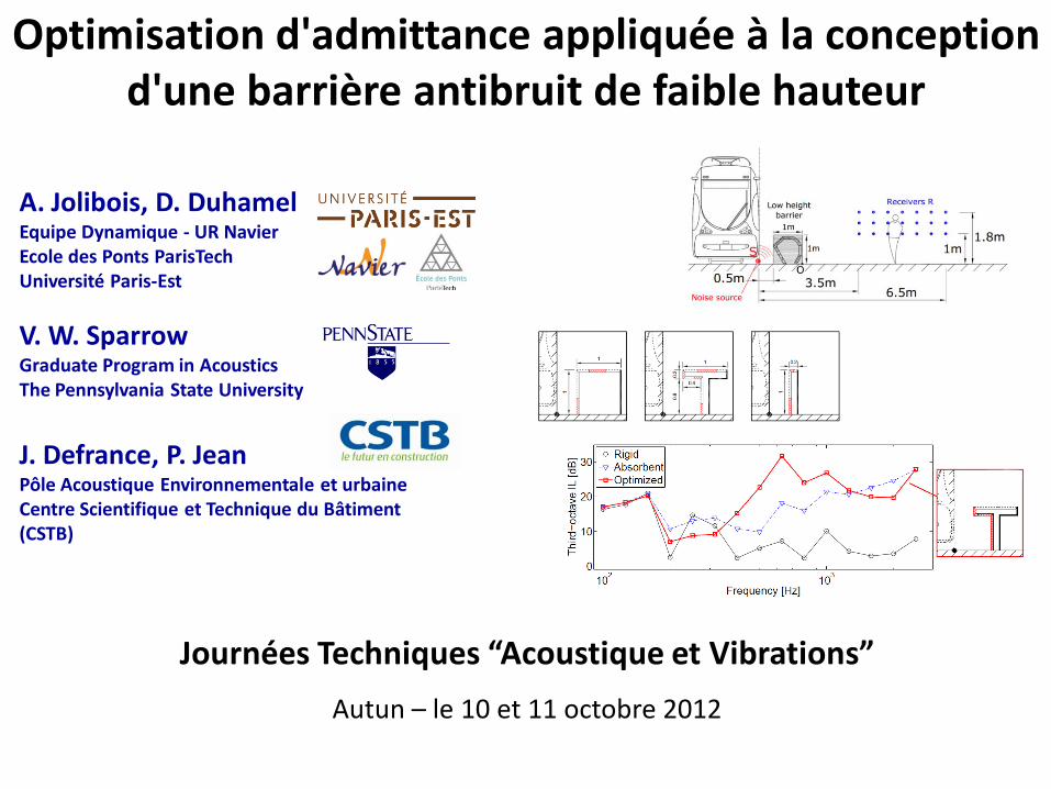
A. Jolibois, D. DuhamelEquipe Dynamique - UR NavierEcole des Ponts ParisTechUniversité Paris-Est
V. W. SparrowGraduate Program in AcousticsThe Pennsylvania State University
J. Defrance, P. JeanPôle Acoustique Environnementale et urbaineCentre Scientifique et Technique du Bâtiment (CSTB)
Optimisation d'admittance appliquée à la conception d'une barrière antibruit de faible hauteur
Journées Techniques “Acoustique et Vibrations”
Autun – le 10 et 11 octobre 2012
2
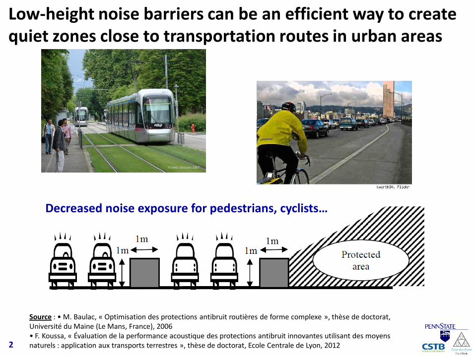
Decreased noise exposure for pedestrians, cyclists…
Low-height noise barriers can be an efficient way to create quiet zones close to transportation routes in urban areas
Source : • M. Baulac, « Optimisation des protections antibruit routières de forme complexe », thèse de doctorat, Université du Maine (Le Mans, France), 2006• F. Koussa, « Évaluation de la performance acoustique des protections antibruit innovantes utilisant des moyens naturels : application aux transports terrestres », thèse de doctorat, Ecole Centrale de Lyon, 2012
3
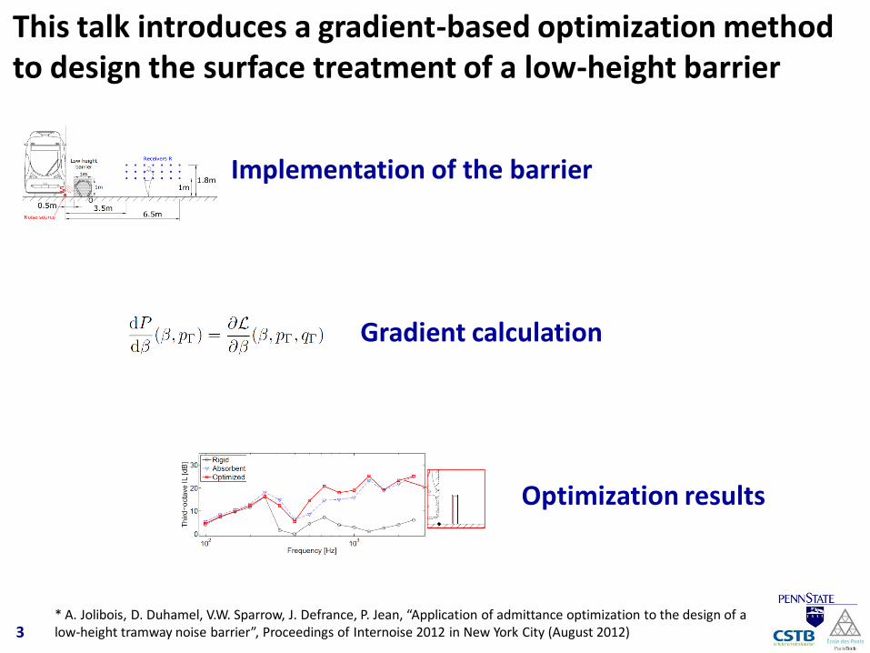
This talk introduces a gradient-based optimization method to design the surface treatment of a low-height barrier
Optimization results
Implementation of the barrier
Gradient calculation
* A. Jolibois, D. Duhamel, V.W. Sparrow, J. Defrance, P. Jean, “Application of admittance optimization to the design of a low-height tramway noise barrier”, Proceedings of Internoise 2012 in New York City (August 2012)
4
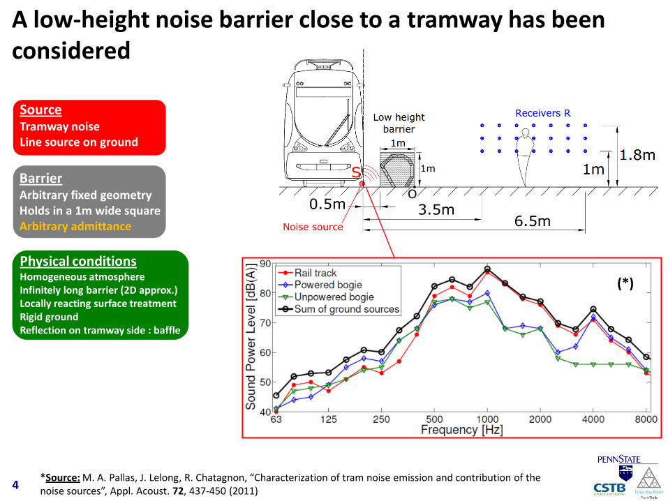
A low-height noise barrier close to a tramway has been considered
*Source: M. A. Pallas, J. Lelong, R. Chatagnon, “Characterization of tram noise emission and contribution of the noise sources”, Appl. Acoust. 72, 437-450 (2011)
SourceTramway noiseLine source on ground
BarrierArbitrary fixed geometryHolds in a 1m wide squareArbitrary admittance
Physical conditionsHomogeneous atmosphereInfinitely long barrier (2D approx.)Locally reacting surface treatmentRigid groundReflection on tramway side : baffle
(*)
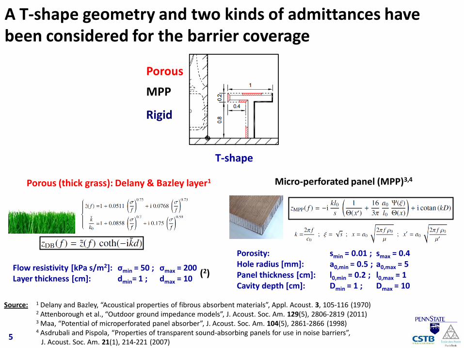
A T-shape geometry and two kinds of admittances have been considered for the barrier coverage
T-shape
Micro-perforated panel (MPP)3,4
Porosity: smin = 0.01 ; smax = 0.4Hole radius [mm]: a0,min = 0.5 ; a0,max = 5Panel thickness [cm]: l0,min = 0.2 ; l0,max = 1Cavity depth [cm]: Dmin = 1 ; Dmax = 10
5
Source: 1 Delany and Bazley, “Acoustical properties of fibrous absorbent materials”, Appl. Acoust. 3, 105-116 (1970)2 Attenborough et al., “Outdoor ground impedance models”, J. Acoust. Soc. Am. 129(5), 2806-2819 (2011)3 Maa, “Potential of microperforated panel absorber”, J. Acoust. Soc. Am. 104(5), 2861-2866 (1998)4 Asdrubali and Pispola, “Properties of transparent sound-absorbing panels for use in noise barriers”,
J. Acoust. Soc. Am. 21(1), 214-221 (2007)
Porous
MPP
Rigid
Porous (thick grass): Delany & Bazley layer1
Flow resistivity [kPa s/m2]: σmin = 50 ; σmax = 200Layer thickness [cm]: dmin= 1 ; dmax = 10
(2)
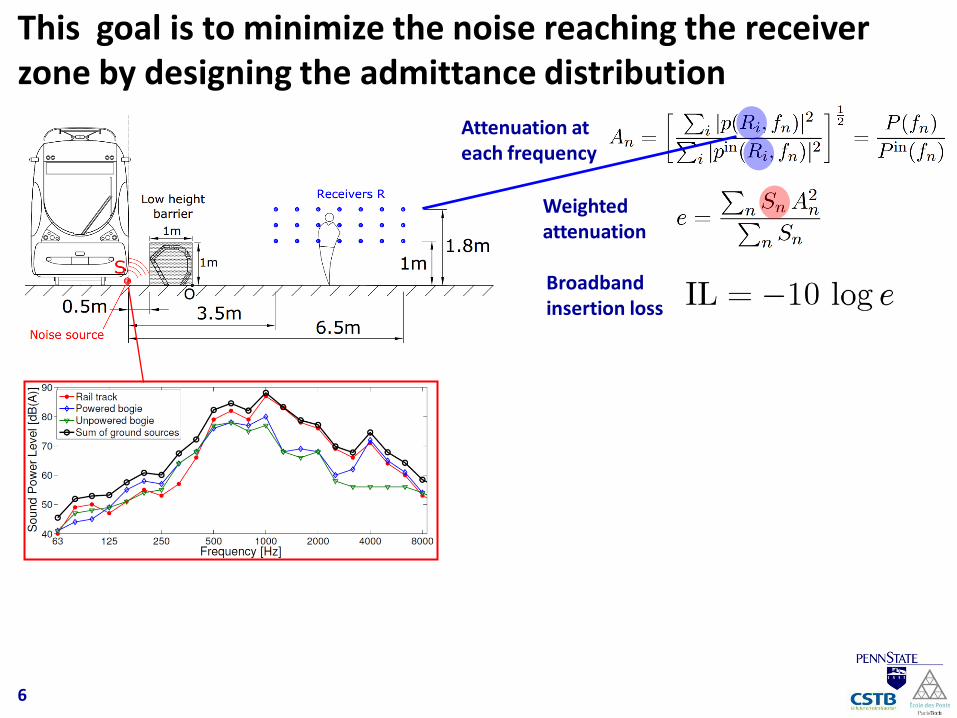
This goal is to minimize the noise reaching the receiver zone by designing the admittance distribution
6
Attenuation at each frequency
Weighted attenuation
Broadband insertion loss
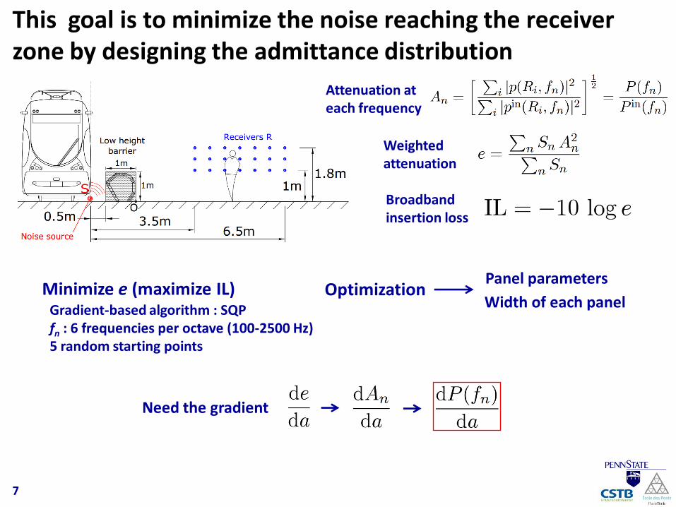
This goal is to minimize the noise reaching the receiver zone by designing the admittance distribution
7
Attenuation at each frequency
Weighted attenuation
Minimize e (maximize IL)
Broadband insertion loss
OptimizationPanel parameters
Width of each panel
Need the gradient
Gradient-based algorithm : SQPfn : 6 frequencies per octave (100-2500 Hz)5 random starting points
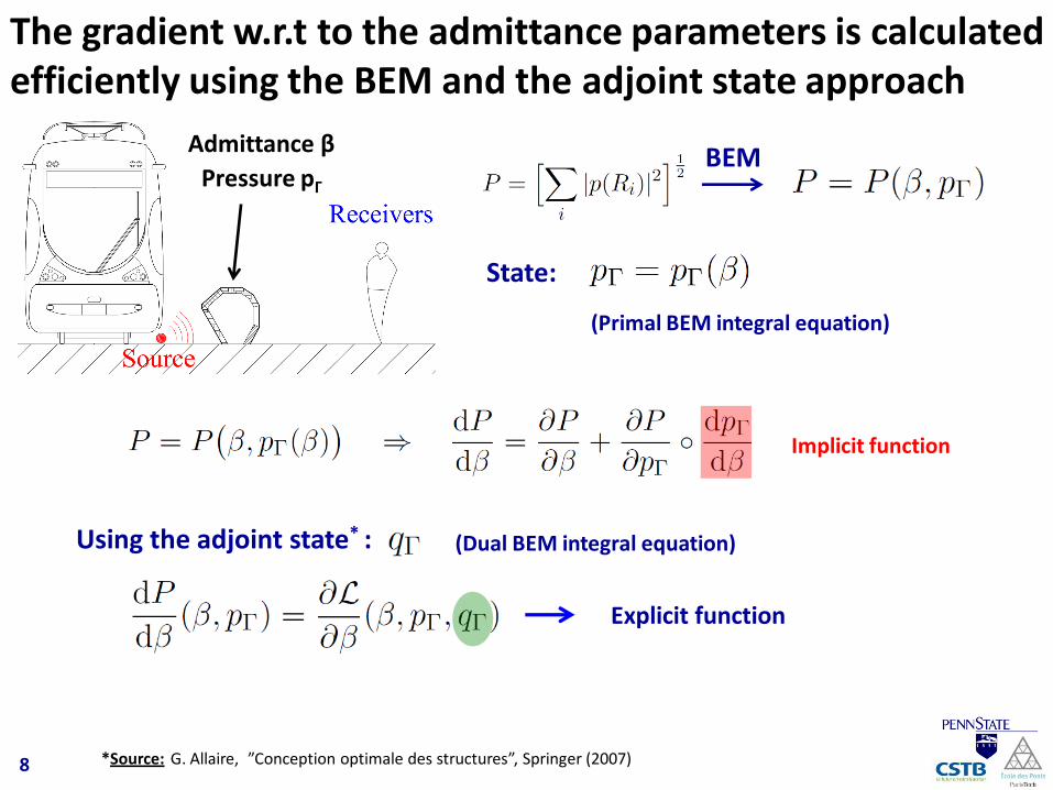
The gradient w.r.t to the admittance parameters is calculated efficiently using the BEM and the adjoint state approach
BEM
(Primal BEM integral equation)
Admittance β
Pressure pΓ
Implicit function
Explicit function
State:
Using the adjoint state* : (Dual BEM integral equation)
8 *Source: G. Allaire, ”Conception optimale des structures”, Springer (2007)
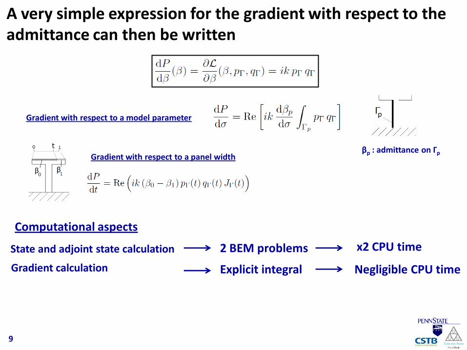
A very simple expression for the gradient with respect to the admittance can then be written
9
Gradient with respect to a model parameter
βp : admittance on ΓpGradient with respect to a panel width
Computational aspects
State and adjoint state calculation
Gradient calculation
2 BEM problems
Explicit integral
x2 CPU time
Negligible CPU time
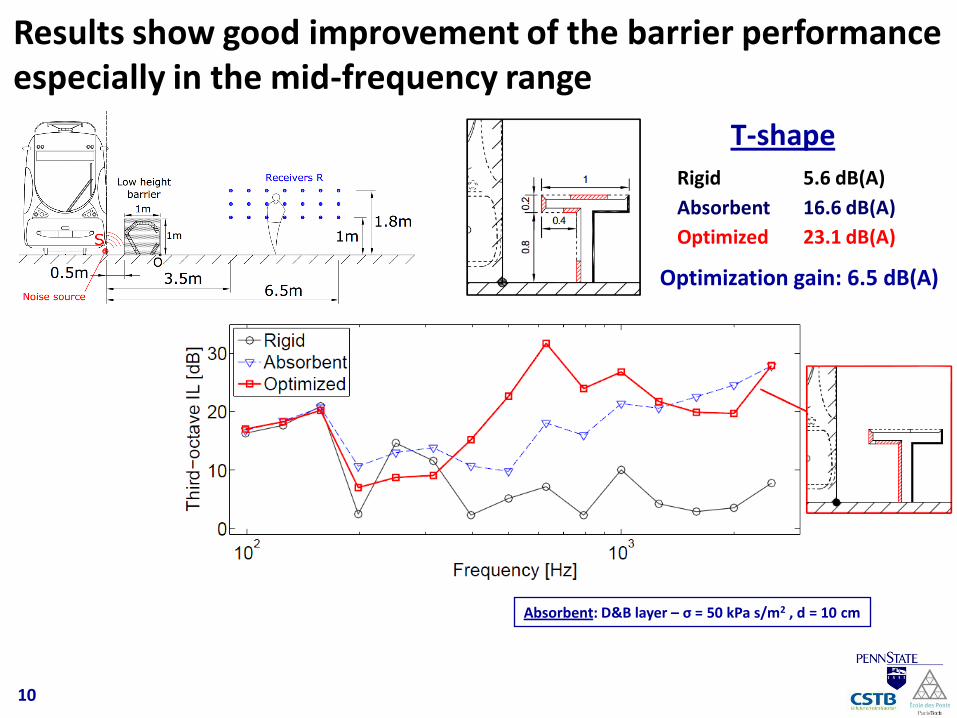
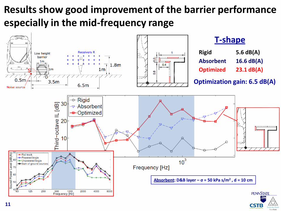
T-shapeRigid 5.6 dB(A)
Absorbent 16.6 dB(A)
Optimized 23.1 dB(A)
Optimization gain: 6.5 dB(A)
Results show good improvement of the barrier performance especially in the mid-frequency range
10
Absorbent: D&B layer – σ = 50 kPa s/m2 , d = 10 cm
T-shapeRigid 5.6 dB(A)
Absorbent 16.6 dB(A)
Optimized 23.1 dB(A)
Optimization gain: 6.5 dB(A)
Results show good improvement of the barrier performance especially in the mid-frequency range
11
Absorbent: D&B layer – σ = 50 kPa s/m2 , d = 10 cm
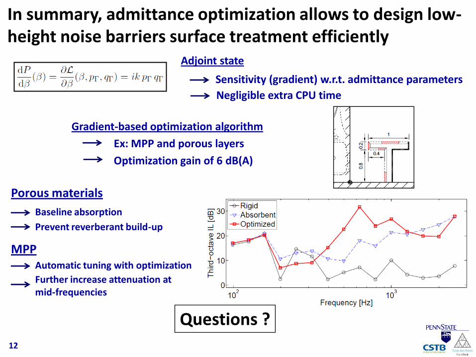
In summary, admittance optimization allows to design low-height noise barriers surface treatment efficiently
Adjoint state
Sensitivity (gradient) w.r.t. admittance parameters
Negligible extra CPU time
Gradient-based optimization algorithm
Porous materials
Ex: MPP and porous layers
Baseline absorption
Prevent reverberant build-up
MPPAutomatic tuning with optimization
Further increase attenuation at mid-frequencies
Questions ?
Optimization gain of 6 dB(A)
12
BACKUP SLIDES
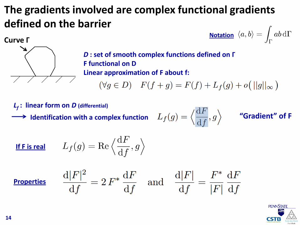
The gradients involved are complex functional gradients defined on the barrier
Curve Γ
D : set of smooth complex functions defined on ΓF functional on DLinear approximation of F about f:
Lf : linear form on D (differential)
If F is real
“Gradient” of F
14
Identification with a complex function
Notation
Properties
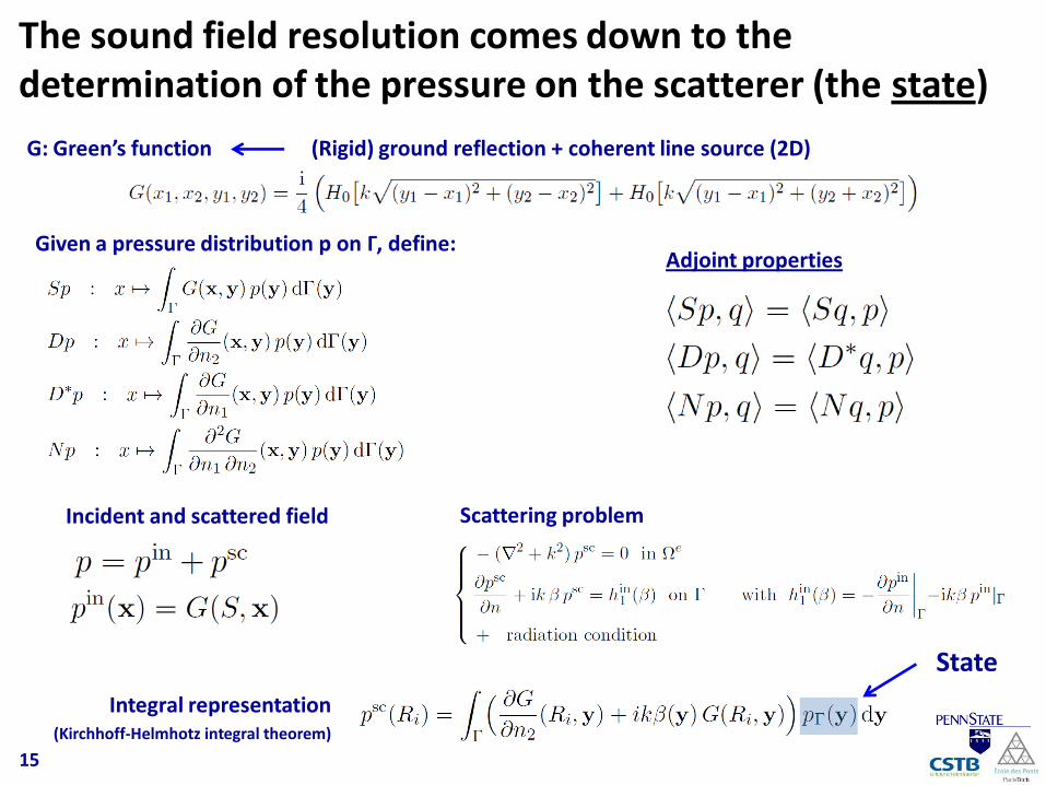
The sound field resolution comes down to the determination of the pressure on the scatterer (the state)
G: Green’s function (Rigid) ground reflection + coherent line source (2D)
Given a pressure distribution p on Γ, define:Adjoint properties
Scattering problem
Integral representation(Kirchhoff-Helmhotz integral theorem)
State
15
Incident and scattered field
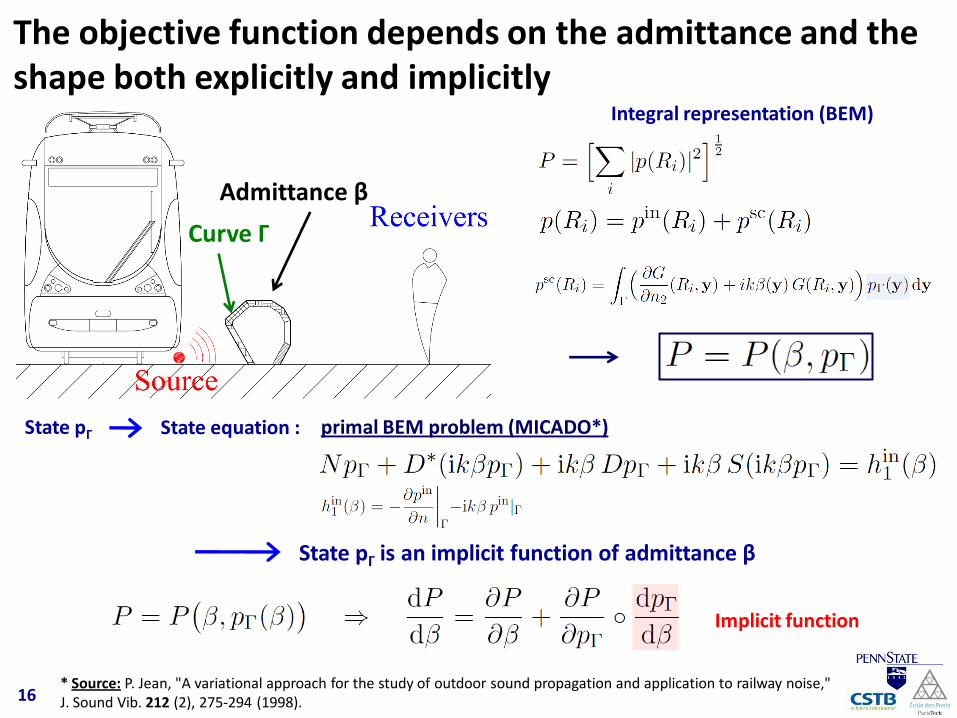
The objective function depends on the admittance and the shape both explicitly and implicitly
Curve Γ
Admittance β
State pΓ State equation :
State pΓ is an implicit function of admittance β
Implicit function
16* Source: P. Jean, "A variational approach for the study of outdoor sound propagation and application to railway noise," J. Sound Vib. 212 (2), 275-294 (1998).
Integral representation (BEM)
primal BEM problem (MICADO*)
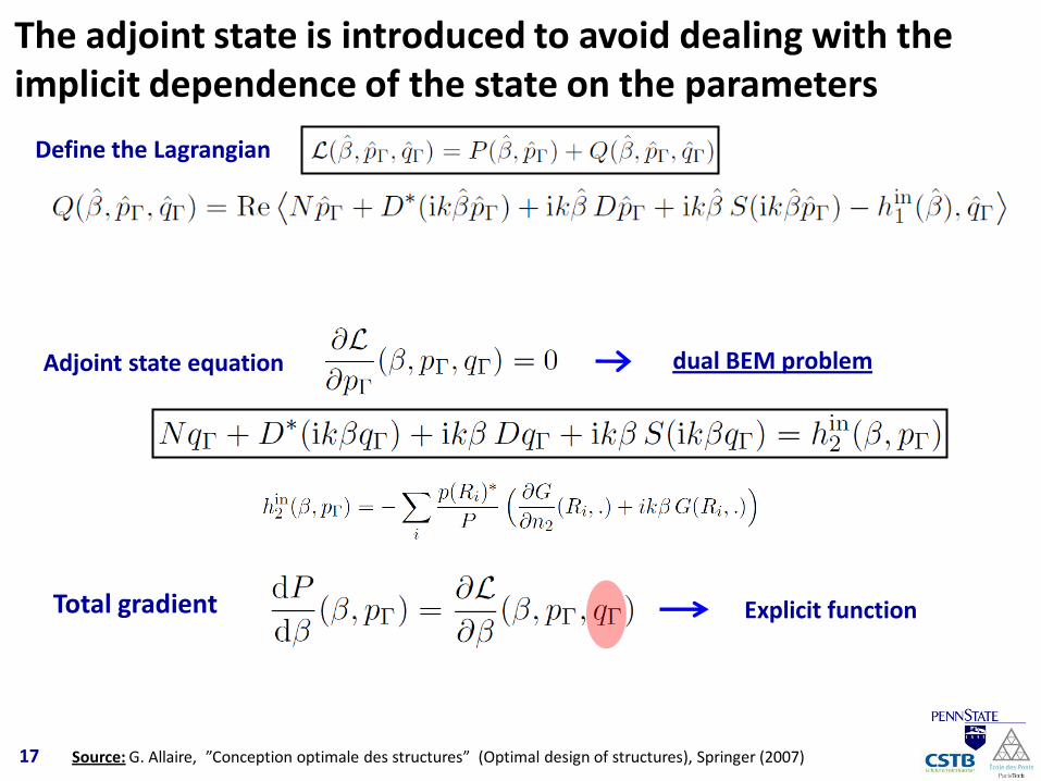
The adjoint state is introduced to avoid dealing with the implicit dependence of the state on the parameters
Define the Lagrangian
Adjoint state equation
Total gradient
17 Source: G. Allaire, ”Conception optimale des structures” (Optimal design of structures), Springer (2007)
dual BEM problem
Explicit function
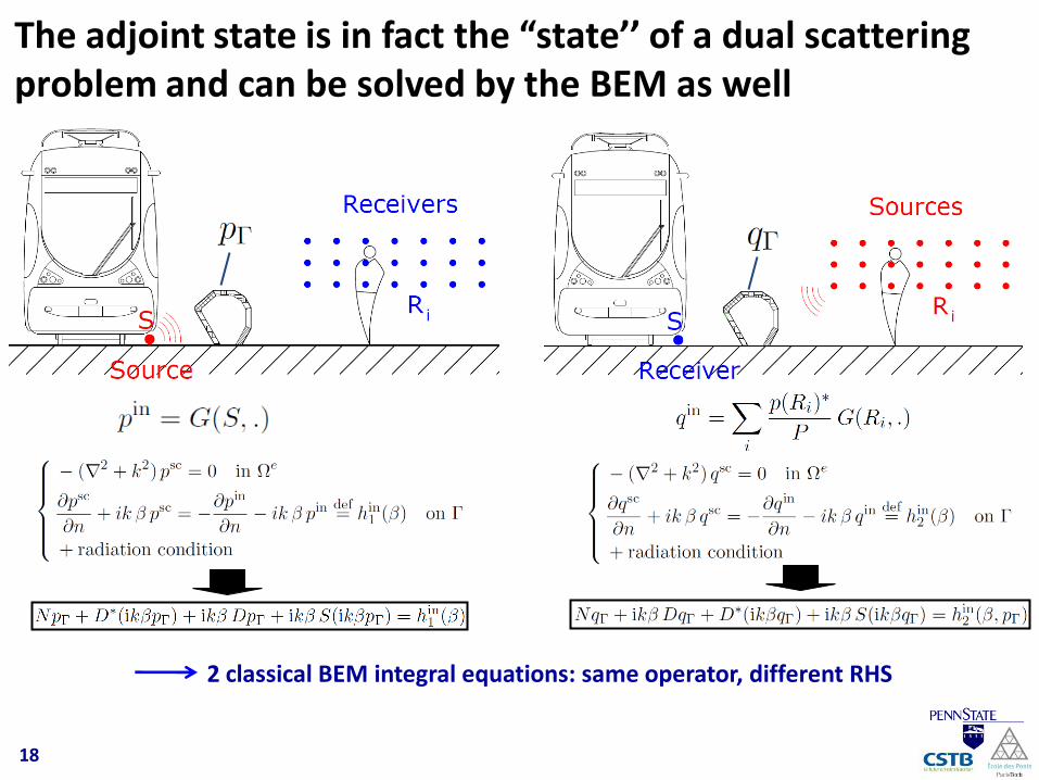
The adjoint state is in fact the “state’’ of a dual scattering problem and can be solved by the BEM as well
2 classical BEM integral equations: same operator, different RHS
18
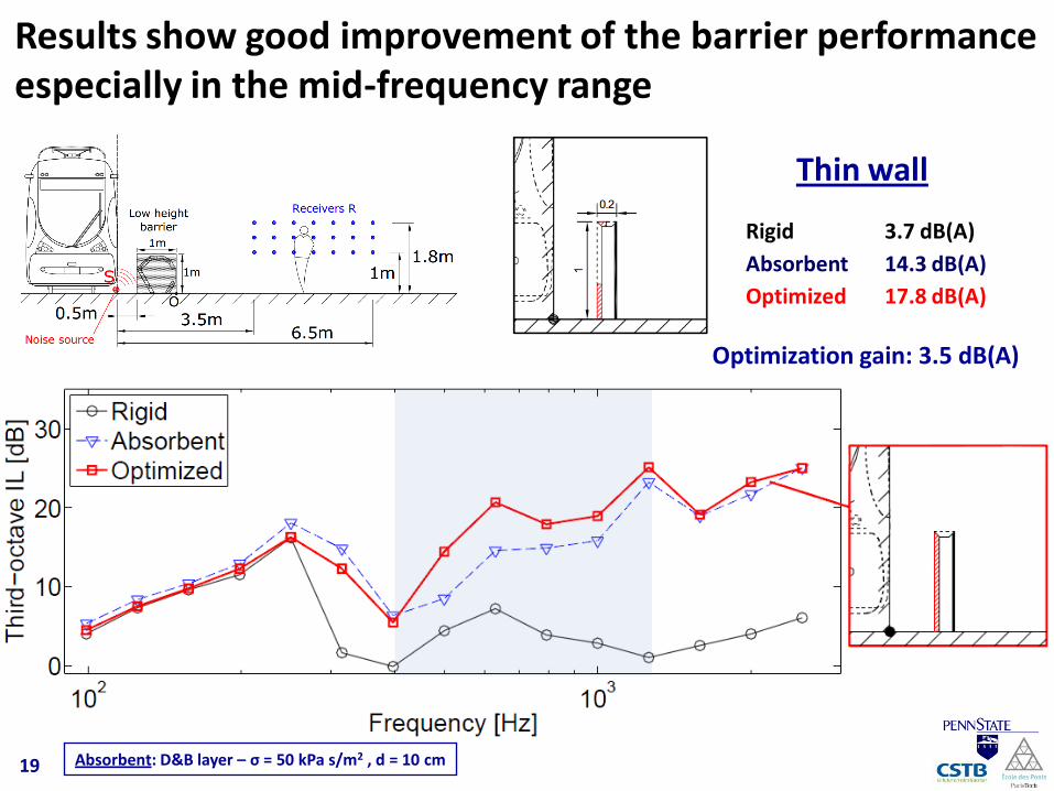
Results show good improvement of the barrier performance especially in the mid-frequency range
Thin wall
Rigid 3.7 dB(A)
Absorbent 14.3 dB(A)
Optimized 17.8 dB(A)
Optimization gain: 3.5 dB(A)
19 Absorbent: D&B layer – σ = 50 kPa s/m2 , d = 10 cm
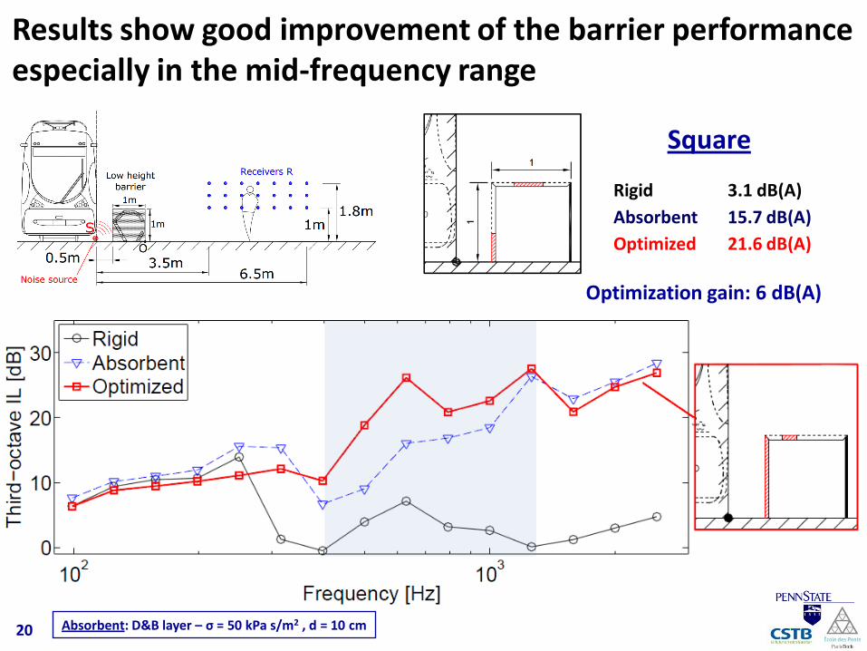
Square
Rigid 3.1 dB(A)
Absorbent 15.7 dB(A)
Optimized 21.6 dB(A)
Optimization gain: 6 dB(A)
Results show good improvement of the barrier performance especially in the mid-frequency range
20 Absorbent: D&B layer – σ = 50 kPa s/m2 , d = 10 cm
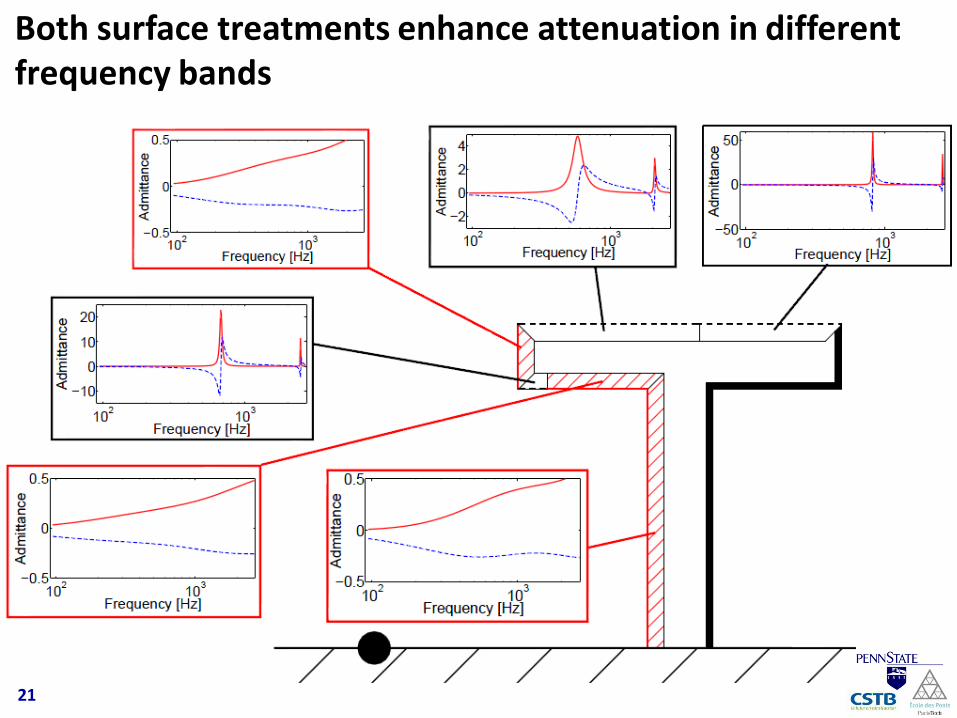
Both surface treatments enhance attenuation in different frequency bands
21
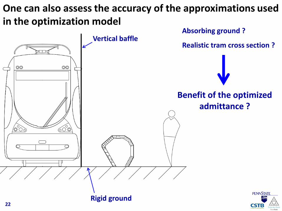
One can also assess the accuracy of the approximations used in the optimization model
Absorbing ground ?
Realistic tram cross section ?Vertical baffle
Rigid ground
Benefit of the optimized admittance ?
22
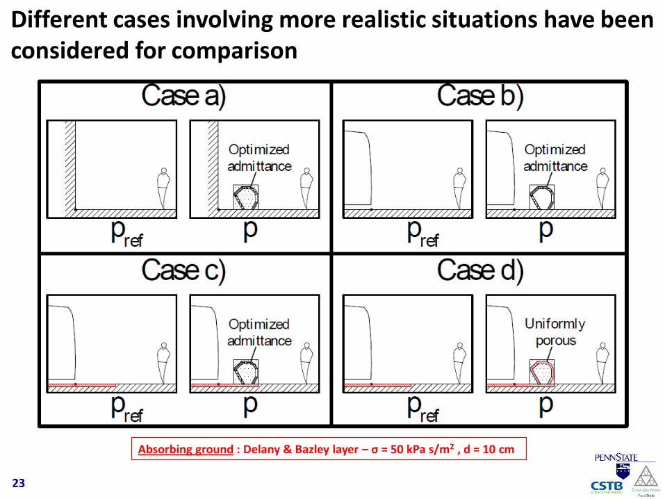
Different cases involving more realistic situations have been considered for comparison
23
Absorbing ground : Delany & Bazley layer – σ = 50 kPa s/m2 , d = 10 cm
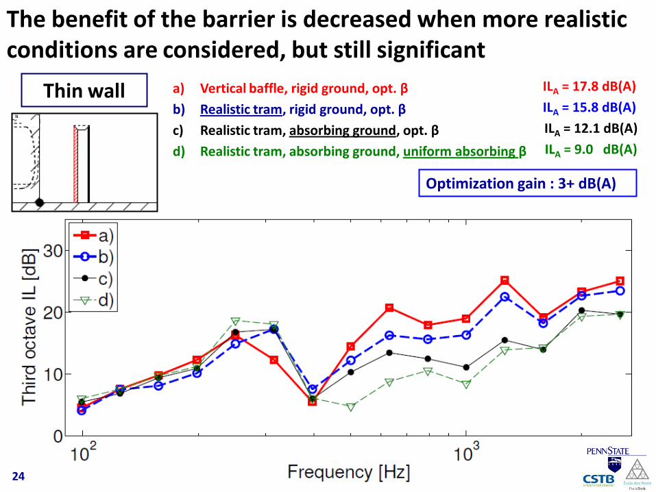
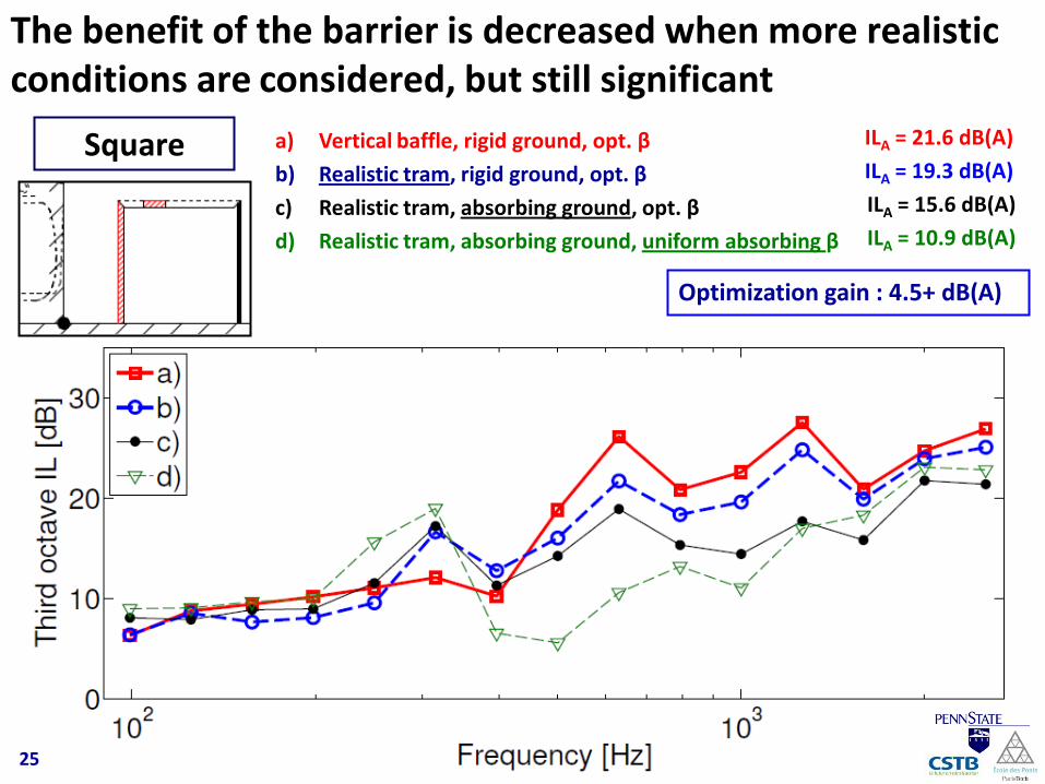
The benefit of the barrier is decreased when more realistic conditions are considered, but still significant
24
a) Vertical baffle, rigid ground, opt. β
b) Realistic tram, rigid ground, opt. β
c) Realistic tram, absorbing ground, opt. β
d) Realistic tram, absorbing ground, uniform absorbing β
ILA = 17.8 dB(A)
ILA = 15.8 dB(A)
ILA = 12.1 dB(A)
ILA = 9.0 dB(A)
Optimization gain : 3+ dB(A)
Thin wall
The benefit of the barrier is decreased when more realistic conditions are considered, but still significant
25
a) Vertical baffle, rigid ground, opt. β
b) Realistic tram, rigid ground, opt. β
c) Realistic tram, absorbing ground, opt. β
d) Realistic tram, absorbing ground, uniform absorbing β
ILA = 21.6 dB(A)
ILA = 19.3 dB(A)
ILA = 15.6 dB(A)
ILA = 10.9 dB(A)
Optimization gain : 4.5+ dB(A)
Square
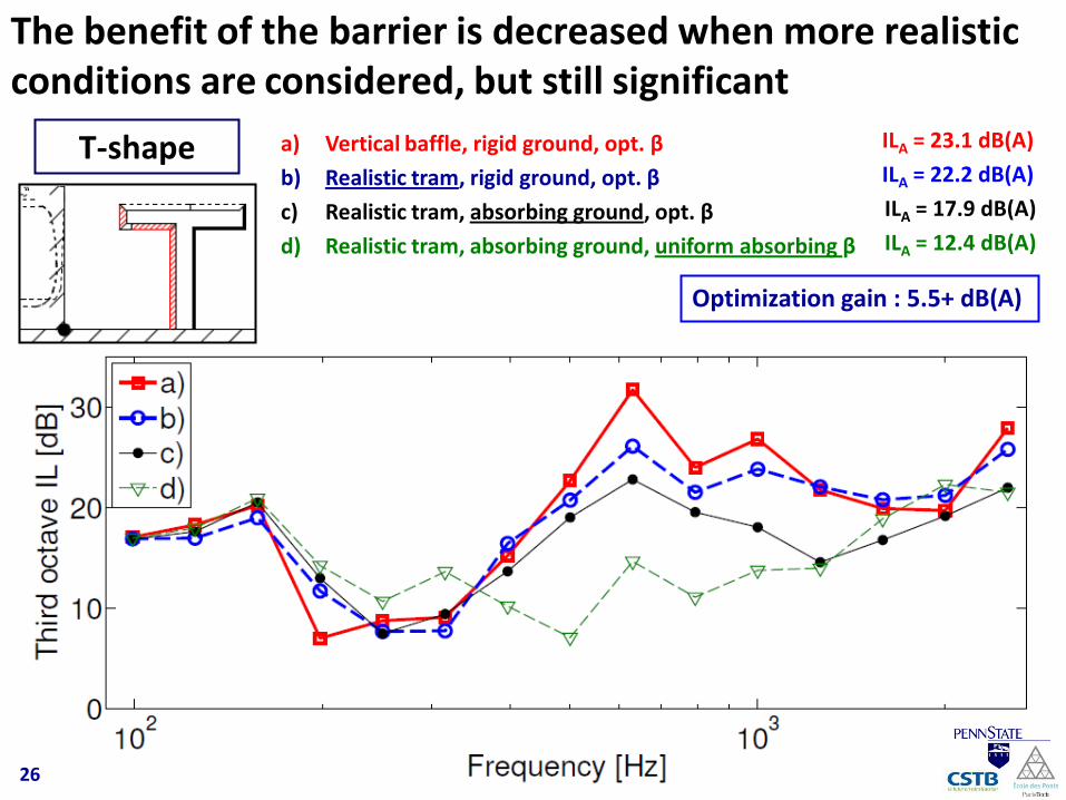
The benefit of the barrier is decreased when more realistic conditions are considered, but still significant
26
a) Vertical baffle, rigid ground, opt. β
b) Realistic tram, rigid ground, opt. β
c) Realistic tram, absorbing ground, opt. β
d) Realistic tram, absorbing ground, uniform absorbing β
ILA = 23.1 dB(A)
ILA = 22.2 dB(A)
ILA = 17.9 dB(A)
ILA = 12.4 dB(A)
Optimization gain : 5.5+ dB(A)
T-shape