Embed Size (px)
Citation preview
Photoelastic modulator for the infrared J. C. Canit and J. N. Chazalviel
J. C. Canit is with Ecole Superieure de Physique et de Chimie Industrielles, Laboratoire d'Optique Physique (CNRS ER 5), 10 rue Vauquelin, 75231 Paris CEDEX 05, France, and J. N. Chazalviel is with Ecole Polytechnique, Laboratoire PMC (CNRS GR 05 0038), Route de Saclay, 91128 Palaiseau CEDEX, France. Received 16 July 1986. 0003-6935/87/010022-02$02.00/0. © 1987 Optical Society of America. Polarization modulation1 has been widely used for about
twenty years for the measurements of circular or linear di-chroism, birefringence, rotatory power, and more recently for ellipsometric studies, e.g., in electrochemistry2 or for monitoring thin-film growth.3 This technique is also used now for high frequency (50 kHz) light chopping, which may be of interest for large diameter and large aperture beams as well as for laser beams. This modulation technique makes it necessary to use a birefringent modulator. Among such modulators, the Pockels cell which requires small aperture beams is no longer frequently used. By contrast, photoelastic devices4-10 are now very popular since they accommodate large aperture beams, require only low voltages, and suffer optical misalignments. We describe here the extension of our previously developed design'7,8 for its use in the infrared region. By comparison with similar existing modulators,9,10
the setting up that we propose here is very easy to build and highly reliable, it exhibits no sizable parasitic birefringence and allows infrared light modulation to larger wavelengths.
A photoelastic piece (P) of polycrystalhne ZnSe is mechanically excited by two piezoelectric transducers (PZT) glued to P at the centers of two opposite faces [Fig. 1(a)]. The transducers, driven by an electric field applied alongy, oscillate along z and produce shear stresses which induce longitudinal standing vibrations in P, at a mechanical eigenfre-quency ƒ. Here P resonates in the fundamental Λ/2 longitudinal bulk mode; the dynamic stress and strain are shown in Fig. 1(a).
In the same figure we show another design which enables the obtention of a higher stress, hence a modulation to higher wavelengths. This is realized by coupling the above piece with two identical silica blocks (b) by means of a soft adhesive compound. Each silica block is itself excited by two piezoelectric ceramic transducers. All six transducers are then fed with such a frequency that the whole system oscil-
22 APPLIED OPTICS / Vol. 26, No. 1 / 1 January 1987
Fig. 1. (a) ZnSe photoelastic modulator. (a) and (b) ZnSe-SiO2 photoelastic modulator.
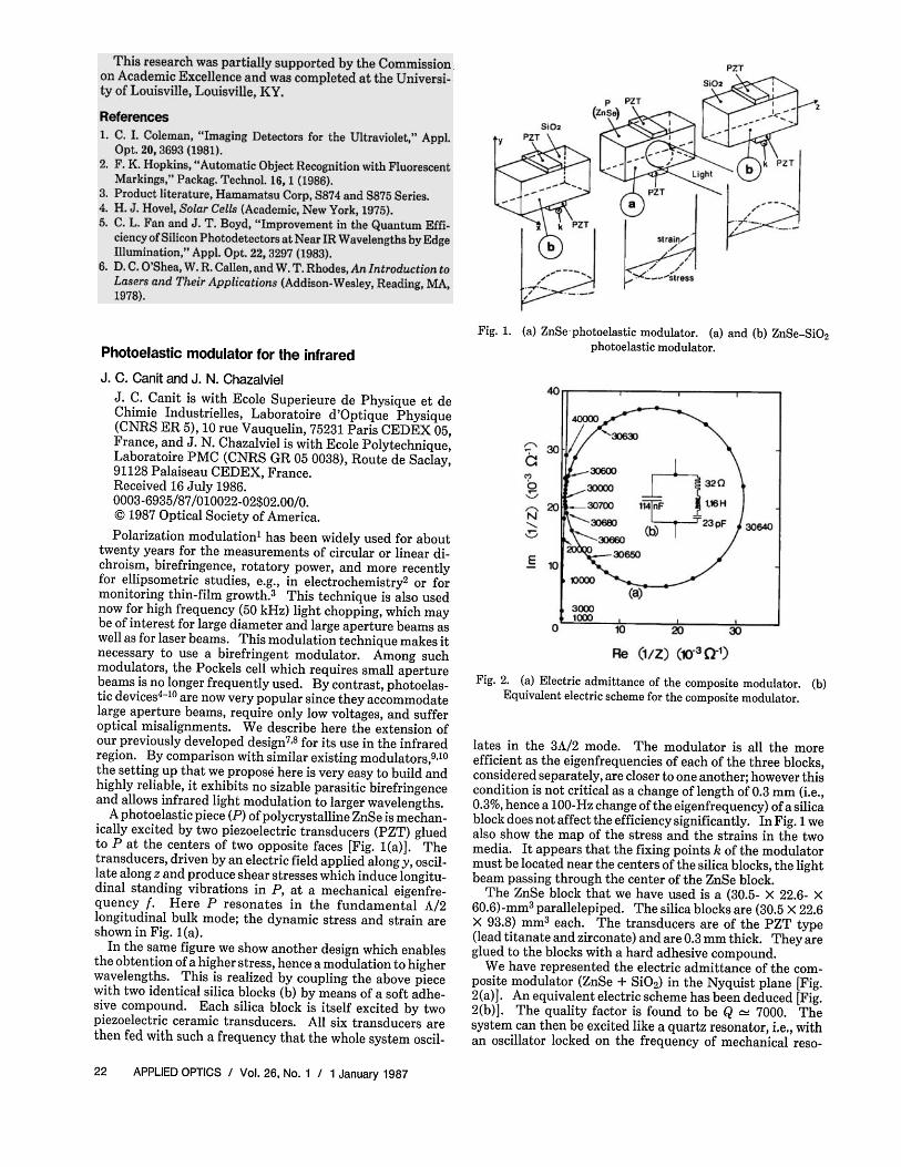
Fig. 2. (a) Electric admittance of the composite modulator. (b) Equivalent electric scheme for the composite modulator.
lates in the 3Λ/2 mode. The modulator is all the more efficient as the eigenfrequencies of each of the three blocks, considered separately, are closer to one another; however this condition is not critical as a change of length of 0.3 mm (i.e., 0.3%, hence a 100-Hz change of the eigenfrequency) of a silica block does not affect the efficiency significantly. In Fig. 1 we also show the map of the stress and the strains in the two media. It appears that the fixing points k of the modulator must be located near the centers of the silica blocks, the Hght beam passing through the center of the ZnSe block.
The ZnSe block that we have used is a (30.5- × 22.6- × 60.6)-mm3 parallelepiped. The silca blocks are (30.5 X 22.6 X 93.8) mm3 each. The transducers are of the PZT type (lead titanate and zirconate) and are 0.3 mm thick. They are glued to the blocks with a hard adhesive compound.
We have represented the electric admittance of the composite modulator (ZnSe + SiO2) in the Nyquist plane [Fig. 2(a)]. An equivalent electric scheme has been deduced [Fig. 2(b)]. The quality factor is found to be Q ≃ 7000. The system can then be excited like a quartz resonator, i.e., with an oscillator locked on the frequency of mechanical reso-
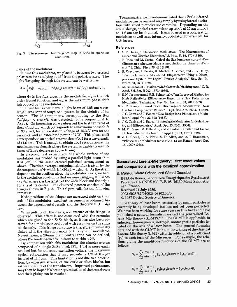
Fig. 3. Time-averaged birefringence map in ZnSe in operating conditions.
nance of the modulator. To test this modulator, we placed it between two crossed
polarizers, its axes lying at 45° from the polarizer axes. The light flux going through this system can be written as
where ф0 is the flux crossing the modulator, Jn is the nth order Bessel function, and φm is the maximum phase shift introduced by the modulator.
In a first test experiment, a light beam of 1.05-μm wavelength was sent through the system in the vicinity of its center. The 2ƒ component, corresponding to the flux ф0J2(φm) × cos4πƒt, was detected. it is proportional to J2(φm). On increasing φm we observed the first ten zeros of the J 2 function, which corresponds to a maximum phase shift of 33.7 rad, for an excitation voltage of 15.3-V rms on the ceramics, and an associated power of 7 W. This phase shift corresponds to an optical retardation of λ/2 for a wavelength of 11.6 μm. This is enough to obtain a λ/4 retardation at the maximum wavelength where the system is usable (transmit-tance of ZnSe decreases above 15 μm).
In a second test experiment, the whole surface of the modulator was probed by using a parallel light beam (λ = 0.64 μm) in the same crossed-polarized arrangement as above. The time-averaged outgoing light flux is given by the dc component of φ, which is l/2ф0[l - J0(φm)] . As the strain depends on the position along the modulator z axis, we had, in the excitation conditions that we were using, φm = 38.5 cos (ΠZ) /L , where L is the length of the ZnSe block and the origin for 2 is at its center. The observed pattern consists of the fringes shown in Fig. 3, This figure calls for the following remarks:
If the positions of the fringes are measured right on the z axis of the modulator, excellent agreement is obtained between the experimental results and the theoretical (1 — J0) law.
When getting off the z axis, a curvature of the fringes is observed. This effect is not associated with the ceramics which are glued to the ZnSe block, as it has also been observed for a modulator equipped with ceramics on the silica blocks only. This fringe curvature is therefore intrinsically linked with the vibration mode of this type of modulator. Nevertheless, a 20-mm diam central zone can be defined, where the birefringence is uniform to within ±7%.
By comparison with this modulator the simpler system composed of a single ZnSe block [Fig. 1(a)] is more easily realized but for the same excitation voltage, the maximum optical retardation that it may provide is λ/2 at 6.5 μm instead of 11.6 μm. This limitation is not due to a destruction, by excessive strains, of the ZnSe or silica blocks, but rather to failure of the transducers. Improved performance may then be hoped if a better optimization of the transducers and their gluing can be reached.
To summarize, we have demonstrated that a ZnSe infrared modulator can be reahzed very simply by using lateral excitation with glued piezoelectric ceramics. Depending on the actual design, optical retardations up to λ/4 at 15 μm and λ/2 at 11.6 μm can be obtained. It can be used as a polarization modulator as well as an intensity modulator, for example, for CO2 lasers.
References 1. A. F. Drake, "Polarization Modulation. The Measurement of
Linear and Circular Dichroism," J. Phys. E. 19,170 (1986). 2. F. Chao and M. Costa, "Calcul du flux lumineux sortant d'un
ellipsometre photometrique a modulation de phase et d'azi-mut," J. Chim. Phys. 78, 411 (1981).
3. B. Drevillon, J. Perrin, R. Marbot, A. Violet, and J. L. Dalby, "Fast Polarization Modulated Ellipsometer Using a Microprocessor System for Digital Fourier Analysis," Rev. Sci. lustrum. 53, 969 (1982).
4. M. Billardon et J. Badoz, "Modulateur de birefringence," C. R. Acad. Sci. Ser. B 262, 1672 (1966).
5. S. N. Jasperson and S. E. Schnatterly, "An Improved Method for High Reflectivity Ellipsometry Based on a New Polarization Modulation Technique," Rev. Sci. Instrum. 40, 761 (1969).
6. J. C. Kemp, "Piezo-Optical Birefringence Modulators: New Use for a Long-Known Effect," J. Opt. Soc. Am. 59, 950 (1969).
7. J. C. Canit and J. Badoz, "New Design for a Photoelastic Modulator," Appl. Opt. 22, 592 (1983).
8. J. C. Canit and J. Badoz, "Photoelastic Modulator for Polarime-try and Ellipsometry," Appl. Opt. 23, 2861 (1984).
9. M. F. Russel, M. Billardon, and J. Badoz "Circular and Linear Dichromator for the Near ir," Appl. Opt. 11, 2375 (1972).
10. J. C. Cheng, L. A. Nafie, S. D. Allen, and A. I. Braunstein, "Photoelastic Modulator for the 0.55- 13-μm Range," Appl. Opt. 15, 1960 (1976).
1 January 1987 / Vol. 26, No. 1 / APPLIED OPTICS 23


![The Herschel-Heterodyne Instrument for the Far-Infrared ... · and Observations of red-shifted [CII]. 2.1 Observations of Water Water is a key ingredient in many environments, including](https://img.pdfslide.fr/doc/110x75/6019355fe47631421832c635/the-herschel-heterodyne-instrument-for-the-far-infrared-and-observations-of.jpg)