Embed Size (px)
Citation preview
Planar waveguide obtained by burying a Ge22As20Se58fiber in As2S3 glass
Quentin Coulombier, Shaoqian Zhang, Xianghua Zhang,* Bruno Bureau,Jacques Lucas, Catherine Boussard-Plédel, Johan Trolès, Laurent Calvez,
Hongli Ma, Sébastien Maurugeon, and Erwan GuillevicLaboratoire des Verres et Céramiques, UMR CNRS 6226 « Sciences Chimiques de Rennes », Université de Rennes I,
Campus de Beaulieu, 35042 Rennes, France
*Corresponding author: xzhang@univ‑rennes1.fr
Received 28 May 2008; revised 3 September 2008; accepted 5 September 2008;posted 9 September 2008 (Doc. ID 96452); published 21 October 2008
We demonstrate the possibility of fabricating an infrared transmitting waveguide by burying fiber inchalcogenide glasses. Two highly mature chalcogenide glasses are used for these experiments. GASIRglass from Umicore IR Glass, Olen, Belgium, with the composition of Ge22As20Se58 is used to draw fibersthat are then buried in an As2S3 glass substrate. The glasses we used are compatible, and we obtained ahigh quality interface. We performed a transmission test with a CO2 laser at 9:3 μm. The potential forextremely low loss planar waveguides is discussed. © 2008 Optical Society of America
OCIS codes: 130.3120, 130.3060.
1. Introduction
Infrared transmitting waveguides are actively stu-died for many potential applications ranging frompollutant detection to exoplanets search [1–4]. TheEuropean space mission DARWIN [5] is conceivedfor the first direct search of terrestrial exoplanetsand to achieve unprecedented spatial resolution inthe infrared wavelength region. The goal is to findplanets with life conditions by detecting the presenceof ozone, water, and carbon dioxide in the atmo-sphere of these planets. These substances, whichare necessary for life, have their fingerprint absorp-tion in the 6–20 μm region. Another reason why theDARWINmission works at this wavelength region isthat there is a much lower emission intensity differ-ence between the planet and the nearby star [5]. Oneof the most important components is a single-modewaveguide that functions between the 6 and 20 μmrange for wavefront filtering to perform destructiveinterference for light from the star and to revealthe planets with much less light emission.
Chalcogenide glasses are transparent in the near-and mid-infrared regions of the spectrum (0:5–10 μmfor sulfides, 0:8–12 μm for selenides, and up to 20 μmfor tellurides [6,7]). The glasses have already beenapplied as different optical material, such as prisms,plates, filters, lenses, and coatings. We are particu-larly interested in telluride glasses, because of theirlarge spectral range. The commonly used techniquesfor fabrication of waveguides are fiber drawing andthin-film deposition [8–10]. The main advantagesof fibers are associated with the highly circularwaveguide with low optical losses.
2. Waveguide Fabrication
We propose to use an innovative technique to fabri-cate an integrated optics device by fiber burying inglass substrates. To demonstrate the feasibility, weselected two highly mature glasses: the GASIR glasscommercialized by Umicore IR Glass, Olen, Belgium,with the composition of Ge22As20Se58 and the well-known As2S3 glass. The experimental procedurefor fabrication of chalcogenide glasses and fibershas been described elsewhere [11] and consists ofputting high purity raw materials into a silica tubethat is sealed under vacuum. The tube that contains
0003-6935/08/315750-03$15.00/0© 2008 Optical Society of America
5750 APPLIED OPTICS / Vol. 47, No. 31 / 1 November 2008
the mixture is homogenized in a rocking furnace, anda glass rod is then obtained by cooling the tube in air.Glass substrates are obtained by slicing the rod intodisks and then polishing the slices. Fibers are pro-duced by drawing the rod.Table 1 shows the glass transition temperature Tg
and refractive index n for the two selected glasses. Itis important to have a Tg of the fiber significantlyhigher than that of the substrate to prevent deforma-tion of the fiber during a burying process by heatingthe substrate to a softening temperature. The twoglasses have compatible refractive indices to formthe core and the cladding of the waveguide. It is im-portant to point out that the refractive index can bemodified on a large scale by making a slight changein the glass composition. The As2S3 substrate has ahigher thermal expansion coefficient than theGe22As20Se58 glass fiber, which means there is a com-pression on the fiber that makes it favorable to in-crease the strength of the component.The fiber burying process is schematically repre-
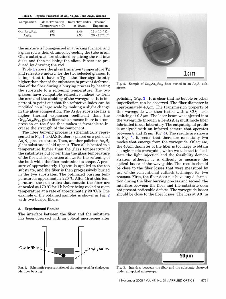
sented in Fig. 1: a GASIR fiber is placed on a polishedAs2S3 glass substrate. Then, another polished As2S3glass substrate is laid upon it. Then all is heated to atemperature higher than the glass temperature ofthe substrates but lower than the glass temperatureof the fiber. This operation allows for the softening ofthe bulk while the fiber maintains its shape. A pres-sure of approximately 10 g=cm is applied to the topsubstrate, and the fiber is then progressively buriedin the two substrates. The optimized burying tem-perature is appoximately 220 °C. After 1h at this tem-perature, the substrates that contain the fiber areannealed at 170 °C for 1 h before being cooled to roomtemperature at a rate of approximately 20 °C=h. Oneexample of the obtained samples is shown in Fig. 2with two buried fibers.
3. Experimental Results
The interface between the fiber and the substratehas been observed with an optical microscope after
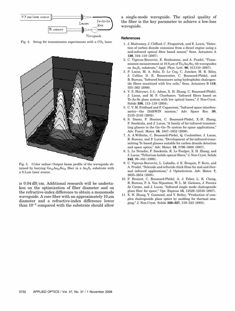
polishing (Fig. 3). It is clear that no bubble or otherimperfection can be observed. The fiber diameter isapproximately 40 μm. The transmission property ofthis waveguide was then tested with a CO2 laseremitting at 9:3 μm. The laser beam was injected intothe waveguide through a Te2As3Se5 multimode fiberfabricated in our laboratory. The output signal profileis analyzed with an infrared camera that operatesbetween 8 and 12 μm (Fig. 4). The results are shownin Fig. 5. It seems that there are essentially twomodes that emerge from the waveguide. Of course,the 40 μm diameter of the fiber is too large to obtaina single-mode waveguide, which we selected to facil-itate the light injection and the feasibility demon-stration although it is difficult to measure theoptical losses of the waveguide. The results shouldbe close to the fiber losses that were measured byuse of the conventional cutback technique for tworeasons. First, the fiber does not have any deforma-tion during the fiber burying process and second, theinterface between the fiber and the substrate doesnot present noticeable defects. The waveguide lossesshould be close to the fiber losses. The loss at 9:3 μm
Table 1. Physical Properties of Ge22As20Se58 and As2S3 Glasses
Composition Glass TransitionTemperature (°C)
Refractive Indexat 10 μm
ThermalExpansion
Ge22As20Se58 292 2.49 17 × 10−6 K−1
As2S3 170 2.38 20 × 10−6 K−1
Fig. 1. Schematic representation of the setup used for chalcogen-ide fiber burying.
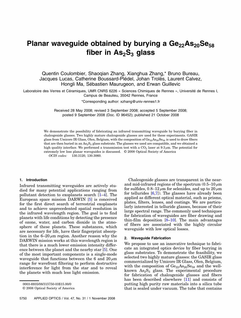
Fig. 2. Sample of Ge22As20Se58 fiber buried in an As2S3 sub-strate.
Fig. 3. Interface between the fiber and the substrate observedunder an optical microscope.
1 November 2008 / Vol. 47, No. 31 / APPLIED OPTICS 5751
is 0:04dB=cm. Additional research will be underta-ken on the optimization of fiber diameter and onthe refractive-index difference to obtain a monomodewaveguide. A core fiber with an approximately 10 μmdiameter and a refractive-index difference lowerthan 10−2 compared with the substrate should allow
a single-mode waveguide. The optical quality ofthe fiber is the key parameter to achieve a low-losswaveguide.
References
1. J. Mulrooney, J. Clifford, C. Fitzpatrick, and E. Lewis, “Detec-tion of carbon dioxide emissions from a diesel engine using amid-infrared optical fibre based sensor,” Sens. Actuators A136, 104–110 (2007).
2. C. Vigreux-Bercovici, E. Bonhomme, and A. Pradel, “Trans-mission measurement at 10:6 μm of Te2As3Se5 rib waveguideson As2S3 substrate,” Appl. Phys. Lett. 90, 011110 (2007).
3. P. Lucas, M. A. Solis, D. Le Coq, C. Juncker, M. R. Riley,J. Collier, D. E. Boesewetter, C. Boussard-Plédel, andB. Bureau, “Infrared biosensors using hydrophobic chalcogen-ide fibers sensitized with live cells,” Sens. Actuators B 119,355–362 (2006).
4. V. S. Shiryaev, J.-L. Adam, X. H. Zhang, C. Boussard-Plédel,J. Lucas, and M. F. Churbanov, “Infrared fibers based onTe-As-Se glass system with low optical losses,” J. Non-Cryst.Solids 336, 113–119 (2004).
5. C. V. M. Fridlund and F. Capaccioni, “Infrared space interfero-metry—the DARWIN mission,” Adv. Space Res. 30,2135–2145 (2002).
6. S. Danto, P. Houizot, C. Boussard-Plédel, X.-H. Zhang,F. Smektala, and J. Lucas, “A family of far-infrared transmit-ting glasses in the Ga–Ge–Te system for space applications,”Adv. Funct. Mater. 16, 1847–1852 (2006).
7. A. A.Wilhelm, C. Boussard-Plédel, Q. Coulombier, J. Lucas,B. Bureau, and P. Lucas, “Development of far-infrared-trans-mitting Te based glasses suitable for carbon dioxide detectionand space optics,” Adv. Mater. 19, 3796–3800 (2007).
8. L. Le Neindre, F. Smektala, K. Le Foulgoc, X. H. Zhang, andJ. Lucas, “Tellurium halide optical fibers,” J. Non-Cryst. Solids242, 99–103 (1998).
9. C. Vigreux-Bercovici, L. Labadie, J. E. Broquin, P. Kern, andA. Pradel, “Selenide and telluride thick films for mid and ther-mal infrared applications,” J. Optoelectron. Adv. Mater. 7,2625–2634 (2005).
10. P. Houizot, C. Boussard-Plédel, A. J. Faber, L. K. Cheng,B. Bureau, P. A. Van Nijnatten, W. L. M. Gielesen, J. Pereirado Carmo, and J. Lucas, “Infrared single mode chalcogenideglass fiber for space,” Opt. Express 15, 12529–12538 (2007).
11. X. H. Zhang, Y. Guimond, and Y. Bellec, “Production of com-plex chalcogenide glass optics by molding for thermal ima-ging,” J. Non-Cryst. Solids 326–327, 519–523 (2003).
Fig. 4. Setup for transmission experiments with a CO2 laser.
Fig. 5. (Color online) Output beam profile of the waveguide ob-tained by burying Ge22As20Se58 fiber in a As2S3 substrate witha 9:3 μm laser source.
5752 APPLIED OPTICS / Vol. 47, No. 31 / 1 November 2008