Embed Size (px)
Citation preview
Preparation of Transparent PMMA/Fe(IO3)3 Nanocomposite Films fromMicroemulsion Polymerization
Latifa Houf,1 Yannick Mugnier,1 Didier Rouxel,2 Ronan Le Dantec,1 Laurent Badie,2 Brice Vincent,2
C�ecile Coustal,3 Sandrine Beauquis,1 Charlotte Thevenet,3 Christine Galez1
1Universit�e de Savoie, SYMME, BP 80439, 74944, Annecy Le Vieux, Cedex, France2D�epartement P2M-UMR CNRS n�7198, Institut Jean Lamour, Universite Henri Poincar�e Nancy 1, BP 239, 54506,Vandoeuvre-les-Nancy, Cedex, France3PLASTIPOLIS, Pole de comp�etitivit�e Plasturgie, BP 10029 Bellignat, 180 rue Pierre et Marie Curie, 01115 Oyonnax,Cedex, FranceCorrespondence to: Y. Mugnier (E -mail: [email protected]).
ABSTRACT: Polymethyl methacrylate (PMMA)/Fe(IO3)3 nanocomposite thin films are obtained by in situ particle generation in
microemulsions and subsequent photopolymerization of a mixture containing methyl methacrylate, trimethylolpropane triacrylate,
and crystallized iron iodate (Fe(IO3)3) nanorods. Hyper-Rayleigh scattering measurements combined with X-ray diffraction,
transmission electron microscopy, and dynamic light scattering are first used to probe in situ the crystallization kinetics of iron iodate
nanorods in water-in-oil microemulsions prepared with methyl methacrylate as the oil phase and marlophen NP12 as a surfactant.
Trimethylolpropane triacrylate is then added as a crosslinker before spin-coating. Films are deposited on glass substrates for the
nonlinear optical characterizations and on silicon wafers for the piezoelectric and mechanical measurements. Nanocomposite films
treated by corona discharge are finally characterized through optical microscopy, laser Doppler vibrometry, and Brillouin spectroscopy.
VC 2013 Wiley Periodicals, Inc. J. Appl. Polym. Sci. 130: 1203–1211, 2013
KEYWORDS: colloids; crystallization; nanoparticles; nanowires and nanocrystals; nanostructured polymers; dielectric properties
Received 27 December 2012; accepted 9 March 2013; Published online 19 April 2013DOI: 10.1002/app.39271
INTRODUCTION
As an alternative to bulk materials, organic/inorganic polymers
and clay-based nanocomposites can find promising appli-
cations in nonlinear optics1–3 and in the field of piezoelectric
sensors.4–6 Synthesis and microstructuring of bulk crystals, for
instance lithium niobate, indeed require expensive and delicate
steps7 so that the nanocomposite approach receives more and
more attention due to the conformability, versatility, lower den-
sity, and easy shaping of the polymer matrix as well as the pos-
sibility to benefit from the intrinsic functional properties of its
inorganic constituents.8–11 However, as far as noncentrosymmet-
ric fillers are concerned, the “tensorial nature” of piezoelectricity
and nonlinear optics implies a homogeneous dispersion of the
nanoparticles within the matrix together with a strict control of
their individual orientation in order to obtain a significant con-
tribution of the inorganic fillers.12
Because of its polar structure and facile synthesis from copreci-
pitation in aqueous solution, iron iodate is here chosen as a
model material for the inorganic part.13,14 The nonlinear optical
properties of Fe(IO3)3 were already demonstrated from powder
measurements15 and also at the single nanocrystal scale in a se-
ries of proof-of-concept experiments16–18 focused on the use of
nanometer-sized acentric nanocrystals, also called “harmonic
labels,” as new nonresonant exogenous biomarkers for second
harmonic generation (SHG) microscopy.19 Fe(IO3)3 nanopar-
ticles crystallize in the space group P63 so that piezoelectric
properties are allowed by the crystal structure even though
measurements are not yet available because of the difficulty of
obtaining quantitative values on nanocrystals by piezoresponse
force microscopy and of growing bulk single crystals.20 On the
other hand, the needle-like Fe(IO3)3 crystalline nanoparticles
obtained so far by coprecipitation of Fe(NO3)3A9H2O and
HIO3 in various sodium bis(2-ethylhexyl) sulfosuccinate (AOT)/
alkane/water ternary systems are good candidates to prepare
transparent functional polymers with optimized piezoelectric
response.12 The growth mechanism from water-in-oil microe-
mulsions, clearly associated to an aggregation-induced crystalli-
zation of 10–20 nm amorphous precursor particles, leads to the
formation of small crystalline nanorods with diameter and
VC 2013 Wiley Periodicals, Inc.
WWW.MATERIALSVIEWS.COM WILEYONLINELIBRARY.COM/APP J. APPL. POLYM. SCI. 2013, DOI: 10.1002/APP.39271 1203
length below 30 and 200 nm, respectively.21 The nanometer size
and the absence of aggregation are strong requirements in order
to keep the transparency of the resulting nanocomposite
material.8
In terms of preparation methods, polymer nanocomposites are
always obtained after a primary dispersion of nanoparticles in a
liquid, which can be a polymer melt, a polymer solvent or a
monomer.8 If dry powders are used as starting materials, power-
ful sonication treatments22 are helpful to reduce the size of pri-
mary agglomerates. However, residual aggregates can limit the
optical transparency, deteriorate the homogenized mechanical
properties and here, prevent a unique particle orientation. Addi-
tionally, phase separation and sedimentation are commonly
observed with inorganic nanoparticles that often tend to ag-
glomerate. Two strategies were thus developed to preserve a ho-
mogeneous dispersion, namely the “in-situ polymerization” and
the “in-situ particle generation” approaches.8,11 In the former
case, particles are dispersed in a monomer solvent after surface
modification by using grafting techniques or by adsorption of
amphiphilic molecules or polymerizable surfactants. For the lat-
ter, if inorganic nanocrystals can be synthesized by a coprecipi-
tation reaction in water, polymerization of reverse w/o
monomer microemulsions is very convenient due to the tem-
plating-effect associated with the reaction medium and to the
availability of various surfactants. This technique was already
successfully applied by Henle and Kaskel for the preparation of
transparent photochromic nanocomposites based on BiOX
(X 5Cl, I)10 and by Althues et al. for luminescent YVO4:Eu/
polymer nanocomposites.9 A similar route is used in this work
combined with a corona discharge treatment to promote the
orientation of the polar Fe(IO3)3 nanofillers. After photopoly-
merization, the polymer matrix consists in polymethyl methac-
rylate (PMMA), a well-known transparent thermoplastic
polymer for which the incorporation of inorganic (centrosym-
metric) fillers like SiO2 was already described.23,24 Similarly, the
homogeneous dispersion of inorganic acentric fillers such as
ZnO nanocrystals appears very pertinent for the development
of transparent PMMA nanocomposites for UV-shielding appli-
cations.25,26 However, implementation of a stable, long-lasting
noncentrosymmetry in a polymer matrix like PMMA is still a
challenge. To our knowledge, only two recent interesting
attempts can be mentioned concerning the incorporation of
KTiOPO4 nanocrystals27 and of DAST chromophores28 in
PMMA.
EXPERIMENTAL
Chemicals
Iron nitrate nonahydrate (Fe(NO3)3.9H2O, �99.99%) and iodic
acid (HIO3, �99.5%) as reactants, AOT (sodium bis(2-ethyl-
hexyl) sulfosuccinate, C20H37NaO7S �99%) as a surfactant,
Trimethylol propanetriacrylate (TMPTA) as a crosslinker and
methyl methacrylate (MMA) as a monomer were purchased
from Sigma-Aldrich (France). Marlophen NP12 (ethoxylated
NonylPhenyl ether with 12 EO units in average) as a nonionic
surfactant and phenyl bis(2,4,6-trim�ethylzol) phosphine
(IrgacureVR
819) as a photoinitiator were provided free of charge
by SASOL and BASF (France), respectively. All chemicals were
used without further purification.
Synthesis and Characterization of Fe(IO3)3 Nanorods
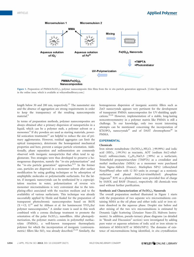
The overall preparation method illustrated in Figure 1 starts
with the preparation of two separate w/o microemulsions con-
taining MMA as the oil phase and either iodic acid or iron ni-
trate dissolved in the aqueous phase. Droplet size before and
after mixing of the two w/o microemulsions is estimated by
Dynamic Light Scattering (Zetasizer Nano-ZS, Malvern Instru-
ments). In addition, pseudo-ternary phase diagrams (as detailed
in “Result and Discussion” section) were investigated by adding
pure water or aqueous solutions of iodic acid or iron nitrate to
mixtures of MMA/AOT or MMA/NP12. The domains of exis-
tence of microemulsions being identified, in situ crystallization
Figure 1. Preparation of PMMA/Fe(IO3)3 polymer nanocomposite thin films from the in situ particle generation approach. [Color figure can be viewed
in the online issue, which is available at wileyonlinelibrary.com.]
ARTICLE
1204 J. APPL. POLYM. SCI. 2013, DOI: 10.1002/APP.39271 WILEYONLINELIBRARY.COM/APP
of iron iodate nanorods in microemulsions is then probed by
time-dependent hyper-rayleigh scattering (HRS) measurements.
The experimental setup was already detailed in a previous
work.21 After centrifugation (Sigma 2–16 centrifuge) of the
reaction medium, the crystalline structure of nanorods is con-
firmed by X-Ray Diffraction (XRD) with Co-Ka (INEL CPS 120
with a position sensitive detector). The size and morphology of
Fe(IO3)3 nanorods are finally investigated by transmission elec-
tron microscopy (Philips CN200) after dispersion in ethanol
and drying of a drop in ambient conditions on a carbon-film-
coated copper grid.
Preparation and Characterization of Nanocomposite Films
After coprecipitation between reactants and formation of crys-
tallized nanoparticles, TMPTA (30.6 wt %), as a crosslinker to
improve the mechanical properties of the PMMA/Fe(IO3)3
nanocomposites,29 and the photoinitiator (3.4 wt % IrgacureVR
819) are added to the MMA microemulsion (the % refers to
the MMA weight content). The mixture is then spin-coated on
standard microscope slides or on silicon wafers. In addition, as
piezoelectric and nonlinear optical properties of the nanocom-
posite films strongly depend on the individual particle orienta-
tion, a corona discharge treatment (10 kV at 7 mm from the film
surface and for 40 min at 75�C) is applied before the polymer-
ization step. The radical photopolymerization of the monomer
is then performed by UV irradiation (DP40, 12*15W, C.I.F.) for
30 min. Note also that the chemical structure of the resulting
nanocomposites were not specifically investigated in this study
because similar drying and UV irradiation conditions are al-
ready known to yield well-polymerized samples.9,30,31
Optical and piezoelectric properties of PMMA/Fe(IO3)3 nano-
composite thin films, treated or not by corona discharge, are
investigated as follows. Detection of a nonlinear optical response
is performed using the Maker-fringes technique. The experi-
mental setup is the same as the one used for HRS21 except that
the signal at 2x is detected in transmission (and not perpendic-
ularly to the incident laser beam) and that the sample is placed
on a rotation plate. Piezoelectric performances of the different
films are assessed with a piezo-d meter (SS01-01, Sensor Technol-
ogy limited, Canada) to estimate the d33 piezoelectric coefficient
and also with laser vibrometry (SIOS SP-S 120, Polytec). Sput-
tered-gold electrodes are first deposited and amplitudes of the me-
chanical vibrations are measured versus the applied voltage.
Finally, mechanical properties of nanocomposite films are char-
acterized by Brillouin spectroscopy. The elastic constants c11
(longitudinal modulus) and c44 (shear modulus) are determined
from the acoustic phonons frequencies measured within the
films with an accuracy of 60.2 GHz.
RESULTS AND DISCUSSION
Large amounts of reactants, and subsequently of dispersed
nanoparticles, are needed to obtain a significant response in
terms of SHG properties and piezoelectricity.12,23 Pseudo-ter-
nary phase diagrams are thus first studied in the following with
MMA as the oil phase and either with AOT as an anionic sur-
factant or with Marlophen NP12 as a nonionic one to find out
the optimum experimental synthesis conditions.
Ternary Phase Diagrams with MMA as the Oil Phase
In regard to AOT, stability regions in the MMA/AOT/water ter-
nary system were already identified at room temperature by the
group of Kaskel and coworkers.23 Following this work, iodic
acid and iron nitrate were dissolved in water and their effects
on the existence of reverse microemulsions were studied. The
concentration of AOT was fixed at 0.5M and we then adjusted
the concentration of iodic acid and iron nitrate, in stoichiomet-
ric amounts, from 6 to 0.3M and from 2 to 0.1M, respectively.
As shown in Table I, the ternary system containing MMA and
AOT does not stabilize large amounts of water. The microemul-
sion phase boundary is even reduced in the presence of aqueous
reactants31 with the consequence that the yield of nanorods is
small. In addition, a low concentration of reactants results in
very slow crystallization kinetics. Typically, for sample D1 (see
Table I), the apparition of Fe(IO3)3 crystalline nanorods is not
detected through HRS measurements before 60 h, even at tem-
perature above 50�C. Besides, after such a period, the viscosity
is high and prevents any spin-coating. We demonstrated earlier
that an increase in temperature and in the concentration of
reactants and surfactants strongly reduces the crystallization
time but such variations are not conceivable here.21 Another
possibility is to reduce the strong binding interactions at the or-
ganic–inorganic interface between surfactants and the surface of
primary amorphous precursors.32 AOT is thus replaced by Mar-
lophen NP12 because nonionic surfactants quicken the overall
crystallization mechanism and also allow higher water contents
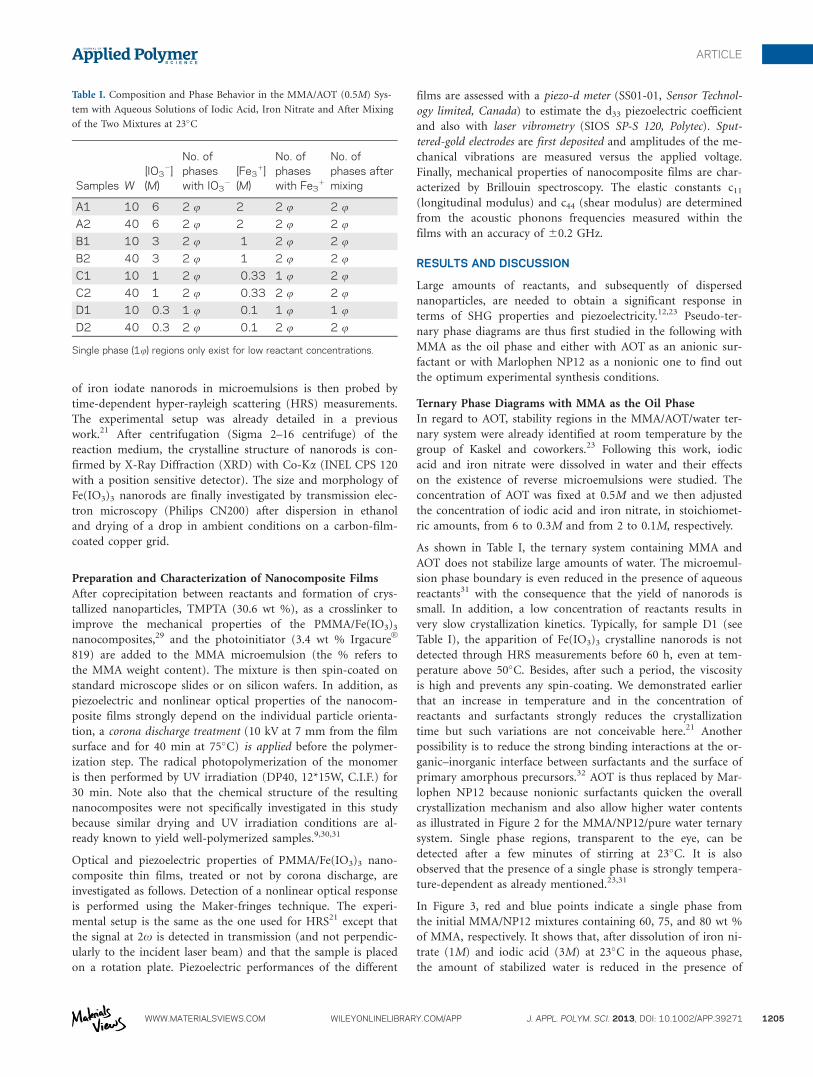
as illustrated in Figure 2 for the MMA/NP12/pure water ternary
system. Single phase regions, transparent to the eye, can be
detected after a few minutes of stirring at 23�C. It is also
observed that the presence of a single phase is strongly tempera-
ture-dependent as already mentioned.23,31
In Figure 3, red and blue points indicate a single phase from
the initial MMA/NP12 mixtures containing 60, 75, and 80 wt %
of MMA, respectively. It shows that, after dissolution of iron ni-
trate (1M) and iodic acid (3M) at 23�C in the aqueous phase,
the amount of stabilized water is reduced in the presence of
Table I. Composition and Phase Behavior in the MMA/AOT (0.5M) Sys-
tem with Aqueous Solutions of Iodic Acid, Iron Nitrate and After Mixing
of the Two Mixtures at 23�C
Samples W[IO3
2](M)
No. ofphaseswith IO3
2
[Fe31]
(M)
No. ofphaseswith Fe3
1
No. ofphases aftermixing
A1 10 6 2 u 2 2 u 2 u
A2 40 6 2 u 2 2 u 2 u
B1 10 3 2 u 1 2 u 2 u
B2 40 3 2 u 1 2 u 2 u
C1 10 1 2 u 0.33 1 u 2 u
C2 40 1 2 u 0.33 2 u 2 u
D1 10 0.3 1 u 0.1 1 u 1 u
D2 40 0.3 2 u 0.1 2 u 2 u
Single phase (1u) regions only exist for low reactant concentrations.
ARTICLE
WWW.MATERIALSVIEWS.COM WILEYONLINELIBRARY.COM/APP J. APPL. POLYM. SCI. 2013, DOI: 10.1002/APP.39271 1205
Fe31 ions. On the contrary, a relatively high concentration of
aqueous iodic acid (3M) has almost no influence and a single
phase region is still obtained for large amounts of water and,
more generally, at high iodic acid concentrations when com-
pared with AOT.
Growth Mechanism of Fe(IO3)3 Nanorods with MMA as the
Oil Phase
Growth mechanisms of iron iodate nanocrystals are studied at
23�C from two mixtures of initial composition given in Table
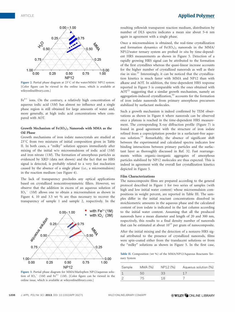
II. In both cases, a “milky” solution appears immediately after
mixing of the initial w/o microemulsions of iodic acid (3M)
and iron nitrate (1M). The formation of amorphous particles as
evidenced by XRD (data not shown) and the fact that no HRS
signal is detected, is probably related to a very fast nucleation
caused by the absence of a single phase (i.e., a microemulsion)
in the reaction medium (see Figure 4).
The lack of transparency precludes any optical applications
based on crystallized noncentrosymmetric fillers. However, we
observe that the addition in excess of an aqueous solution of
IO32 (3M) allows one to obtain a microemulsion as shown in
Figure 4. 10 and 3.5 wt % are thus necessary to recover the
transparency of sample 1 and sample 2, respectively. In the
resulting yellowish transparent reaction medium, distribution by
number of DLS spectra indicates a mean size about 5–6 nm
again in agreement with a single phase.
Once a microemulsion is obtained, the real-time crystallization
and formation dynamics of Fe(IO3)3 nanorods in the MMA/
NP12/water ternary system are probed in situ by time-depend-
ent HRS measurements as shown in Figure 5. Detection of a
rapidly growing HRS signal can be attributed to the formation
of the first crystallites whereas the quasi-linear increase accounts
for the higher number of crystallized nanorods as well as their
rise in size.21 Interestingly, it can be noticed that the crystalliza-
tion kinetics is much faster with MMA and NP12 than with
alkane and AOT. In addition, the time-dependent HRS response
reported in Figure 5 is comparable with the ones obtained with
AOT21 suggesting that a similar growth mechanism, namely an
aggregation-induced crystallization,33 accounts for the formation
of iron iodate nanorods from primary amorphous precursors
stabilized by surfactant molecules.
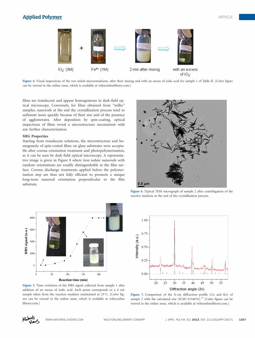
Such a growth mechanism is indeed confirmed by TEM obser-
vations as shown in Figure 6 where nanorods can be observed
once a plateau is reached in the time-dependent HRS measure-
ment. The corresponding X-ray diffraction profile (Figure 7) is
found in good agreement with the structure of iron iodate
refined from a coprecipitation powder in a surfactant-free aque-
ous solution.13 Remarkably, the absence of significant shift
between the experimental and calculated spectra indicates low
binding interactions between primary particles and the surfac-
tant layer as thoroughly discussed in Ref. 32. Fast rearrange-
ments within organic–inorganic aggregates of amorphous
particles stabilized by NP12 molecules are thus expected. This is
indeed in agreement with the overall fast crystallization kinetics
depicted in Figure 5.
Film Characterizations
The nanocomposite films are prepared according to the general
protocol described in Figure 1 for two series of samples (with
high and low initial water content) whose microemulsion com-
positions in weight percent, are reported in Table III. The sam-
ples differ in the initial reactant concentrations dissolved in
stoichiometric amounts in the aqueous phase and the calculated
content of iron iodate is indicated in the last column according
to the initial water content. Assuming that all the produced
nanorods have a mean diameter and length of 20 and 300 nm,
respectively, this results to a final density number of nanorods
that can be estimated at about 1013 per gram of nanocomposite.
After the initial mixing and the detection of a nonzero HRS sig-
nal attributed to the presence of crystallized nanorods, films
were spin-coated either from the translucent solutions or from
the “milky” solutions as shown in Figure 5. In the first case,
Figure 2. Partial phase diagram at 23�C of the water/MMA/ NP12 system.
[Color figure can be viewed in the online issue, which is available at
wileyonlinelibrary.com.]
Figure 3. Partial phase diagram for MMA/Marlophen NP12/aqueous solu-
tion of IO32 (3M) and Fe31 (1M). [Color figure can be viewed in the
online issue, which is available at wileyonlinelibrary.com.]
Table II. Composition (wt %) of the MMA/NP12/Aqueous Reactants Ter-
nary System
Sample MMA (%) NP12 (%) Aqueous solution (%)
1 50 33 17
2 75 18 7
ARTICLE
1206 J. APPL. POLYM. SCI. 2013, DOI: 10.1002/APP.39271 WILEYONLINELIBRARY.COM/APP
films are translucent and appear homogeneous in dark-field op-
tical microscopy. Conversely, for films obtained from “milky”
samples, nanorods at the end the crystallization process tend to
sediment more quickly because of their size and of the presence
of agglomerates. After deposition by spin-coating, optical
inspections of films reveal a microstructure inconsistent with
any further characterization.
SHG Properties
Starting from translucent solutions, the microstructure and ho-
mogeneity of spin-coated films on glass substrates were accepta-
ble after corona orientation treatment and photopolymerization,
as it can be seen by dark-field optical microscopy. A representa-
tive image is given in Figure 8 where iron iodate nanorods with
random orientations are readily distinguishable at the film sur-
face. Corona discharge treatments applied before the polymer-
ization step are thus not fully efficient to promote a unique
long-term nanorod orientation perpendicular to the film
substrate.
Figure 4. Visual inspections of the two initial microemulsions, after their mixing and with an excess of iodic acid for sample 1 of Table II. [Color figure
can be viewed in the online issue, which is available at wileyonlinelibrary.com.]
Figure 5. Time evolution of the HRS signal collected from sample 1 after
addition of an excess of iodic acid. Each point corresponds to a 4 mL
sample taken from the reaction medium maintained at 23�C. [Color fig-
ure can be viewed in the online issue, which is available at wileyonline
library.com.]
Figure 6. Typical TEM micrograph of sample 2 after centrifugation of the
reactive medium at the end of the crystallization process.
Figure 7. Comparison of the X-ray diffraction profile (Co and Ka) of
sample 2 with the calculated one (ICSD #154674).13 [Color figure can be
viewed in the online issue, which is available at wileyonlinelibrary.com.]
ARTICLE
WWW.MATERIALSVIEWS.COM WILEYONLINELIBRARY.COM/APP J. APPL. POLYM. SCI. 2013, DOI: 10.1002/APP.39271 1207
The absence of electric field-induced orientation for spin-coated
films on glass substrates is also evidenced with the Maker-
fringes technique. A constant SH signal is indeed recorded in
Figure 9 for an incident angle varying between 240� and 140�.The decrease on both sides originates from higher Fresnel coef-
ficients. This optically incoherent SHG response can however,
be attributed to the presence of iron iodate nanorods. At per-
pendicular incidence, a qualitative linear increase (data not
shown) is observed from sample F to D and then from sample
C to A in agreement with a higher content of nonlinear scatter-
ing particles.34,35 For each sample, it is also noticed that the SH
intensity increases with a quadratic dependence on the input
laser power, as expected.
Mechanical Characterizations
Most potential applications for these nanocomposites, in piezo-
electric devices as well as in nonlinear optics, require films with
a sufficient mechanical strength. This mechanical behavior can
be expressed in terms of tensile strength or wear resistance of
the polymer film. Several studies have shown that the presence
of nanoparticles could greatly enhance the adhesion of a poly-
mer film by reducing its wear24 or by reducing the formation
and propagation of cracks. In this study, Brillouin spectroscopy
is used to check that films retain a reasonable mechanical stiff-
ness in spite of the eventual inclusions of water within the poly-
mer matrix after the polymerization step. This technique,
particularly attractive for the determination of elastic properties
in solids and liquids, was successfully applied to transparent
crystals and oligomers.36,37 Other works also report that the
sensitivity of Brillouin spectroscopy is also well suited for thin
(thickness in the micrometer range) polymer nanocomposite
films.24,38,39 Here, because a highly reflecting substrate is
required, PMMA/Fe(IO3)3 nanocomposite films are deposited
on silicon wafers. The influence of TMPTA, water and iron
iodate nanorods is studied separately.
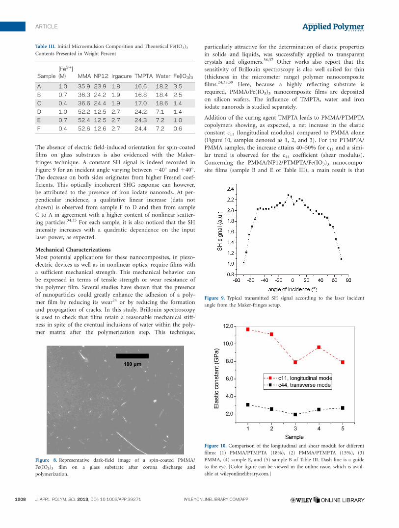
Addition of the curing agent TMPTA leads to PMMA/PTMPTA
copolymers showing, as expected, a net increase in the elastic
constant c11 (longitudinal modulus) compared to PMMA alone
(Figure 10, samples denoted as 1, 2, and 3). For the PTMPTA/
PMMA samples, the increase attains 40–50% for c11 and a simi-
lar trend is observed for the c44 coefficient (shear modulus).
Concerning the PMMA/NP12/PTMPTA/Fe(IO3)3 nanocompo-
site films (sample B and E of Table III), a main result is that
Table III. Initial Microemulsion Composition and Theoretical Fe(IO3)3
Contents Presented in Weight Percent
Sample[Fe31](M) MMA NP12 Irgacure TMPTA Water Fe(IO3)3
A 1.0 35.9 23.9 1.8 16.6 18.2 3.5
B 0.7 36.3 24.2 1.9 16.8 18.4 2.5
C 0.4 36.6 24.4 1.9 17.0 18.6 1.4
D 1.0 52.2 12.5 2.7 24.2 7.1 1.4
E 0.7 52.4 12.5 2.7 24.3 7.2 1.0
F 0.4 52.6 12.6 2.7 24.4 7.2 0.6
Figure 8. Representative dark-field image of a spin-coated PMMA/
Fe(IO3)3 film on a glass substrate after corona discharge and
polymerization.
Figure 9. Typical transmitted SH signal according to the laser incident
angle from the Maker-fringes setup.
Figure 10. Comparison of the longitudinal and shear moduli for different
films: (1) PMMA/PTMPTA (18%), (2) PMMA/PTMPTA (15%), (3)
PMMA, (4) sample E, and (5) sample B of Table III. Dash line is a guide
to the eye. [Color figure can be viewed in the online issue, which is avail-
able at wileyonlinelibrary.com.]
ARTICLE
1208 J. APPL. POLYM. SCI. 2013, DOI: 10.1002/APP.39271 WILEYONLINELIBRARY.COM/APP
the annealing temperature of 75�C applied during the poling
step seems efficient to reduce the initial water content associated
to the microemulsion process. The resulting mechanical proper-
ties are thus not significantly reduced comparatively to PMMA/
PTMTA copolymers. On the contrary, a reinforcement of 7% is
measured for sample E (sample 4 in Figure 10) in relation to
pure PMMA. Interestingly, for a higher initial water and surfac-
tant content, the elastic constant c11 for sample B (sample 5 in
Figure 10), is similar to that of PMMA because of the compen-
sating effect of PTMPTA.
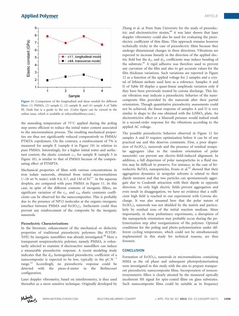
Mechanical properties of films with various concentrations in
iron iodate nanorods, obtained from initial microemulsions
(�18 wt % water) with 0.4, 0.7, and 1M of Fe31 in the aqueous
droplets, are compared with pure PMMA in Figure 11. In this
case, in spite of the different contents of inorganic fillers, no
significant variation of the c11 and c44 elastic constants coeffi-
cients can be observed for the nanocomposites. This is probably
due to the presence of NP12 molecules at the organic–inorganic
interface between PMMA and Fe(IO3)3. Surfactants could thus
prevent any reinforcement of the composite by the inorganic
nanorods.
Piezoelectric Characterizations
In the literature, enhancement of the mechanical or dielectric
properties of traditional piezoelectric polymers like P(VDF-
TrFE) by inorganic nanofillers was already investigated.38 Here a
transparent nonpiezoelectric polymer, namely PMMA, is volun-
tarily selected to examine if electroactive nanofillers can induce
a measurable piezoelectric response. A recent modeling study
indicates that the d33 homogenized piezoelectric coefficient of a
nanocomposite is expected to be low, typically in the pC.N21
range.12 Accordingly, no piezoelectric response could be
detected with the piezo-d-meter in the Berlincourt
configuration.
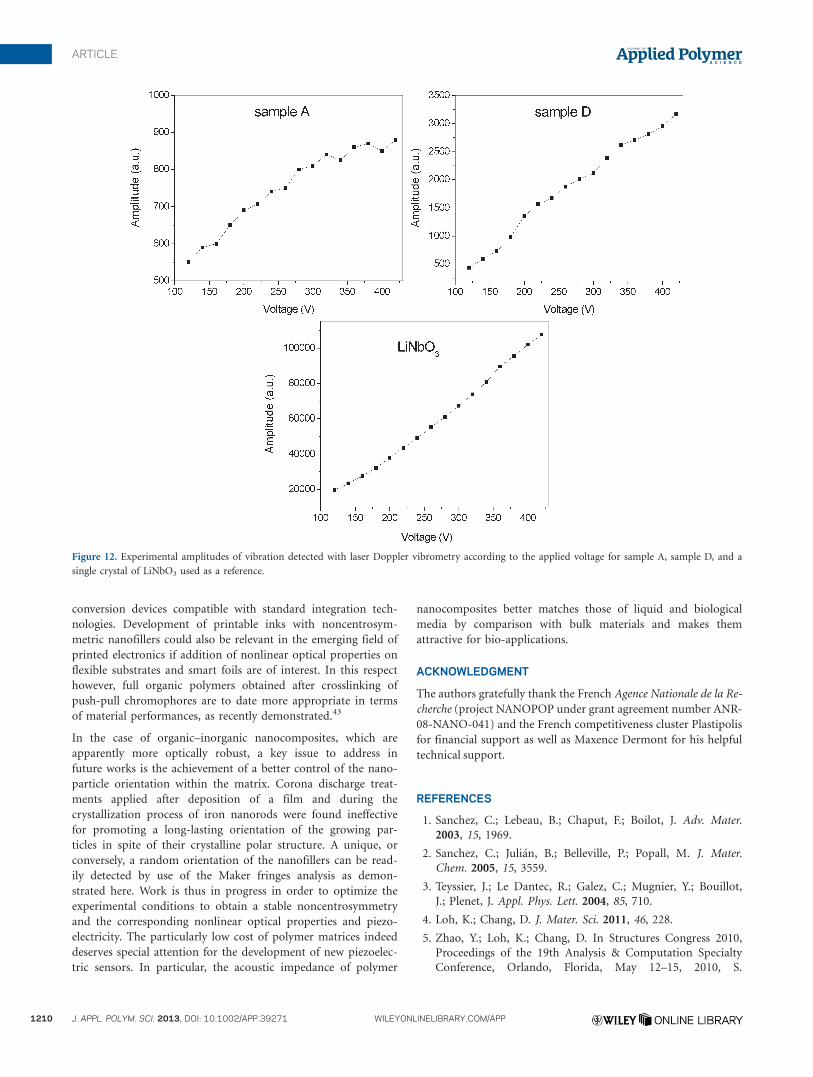
Laser doppler vibrometry, based on interferometry, is thus used
thereafter as a more sensitive technique. Originally developed by
Zhang et al. at Penn State University for the study of piezoelec-
tric and electrostrictive strains,40 it was later shown that laser
doppler vibrometry could also be used for evaluating the piezo-
electric coefficient of thin films. This approach remains however
technically tricky in the case of piezoelectric films because they
undergo dimensional changes in three directions. Vibrations are
expected to increase linearly in the direction of the applied elec-
tric field but the d31 and d32 coefficients may induce bending of
the substrate.41 A rigid adhesive was therefore used to prevent
any curvature of the film and also to get accurate values for the
film thickness variations. Such variations are reported in Figure
12 as a function of the applied voltage for 2 samples and a crys-
tal of lithium niobate used here as a reference. Samples A and
D of Table III display a quasi-linear amplitude variation only if
they have been previously treated by corona discharge. This lin-
ear vibration may indicate a piezoelectric behavior of the nano-
composite film provided by the nanorods after their partial
orientation. Though quantitative piezoelectric assessments could
not be achieved, the linear response of samples A and D is very
similar in shape to the one obtained with the LiNbO3 plate. An
electrostrictive effect or a Maxwell pressure would indeed result
in a second-order response for the vibrations according to the
applied AC voltage.
The possible piezoelectric behavior observed in Figure 12 for
samples A and D requires optimization before it can be of any
practical use and this deserves comments. First, a poor disper-
sion of Fe(IO3)3 nanorods and the presence of residual nonpo-
lar aggregates (due to the random orientation of polar
nanorods) can prevent any electric-field-induced alignment. In
addition, a full dispersion of polar nanoparticles in a fluid ma-
trix may be difficult to preserve. For instance, in the case of fer-
roelectric BaTiO3 nanoparticles, Evans et al.42 showed that their
aggregation dynamics in nonpolar solvents is related to their
dipole moment and that two particles can spontaneously aggre-
gate due to Coulomb attraction with their dipole in opposite
direction. As only high electric fields prevent aggregation and
even result in disaggregation, we have no evidence that a suffi-
cient high field is reached in our experiment with Corona dis-
charge. It was also assumed here that the polar nature of
Fe(IO3)3 nanorods was not shielded by the matrix and particu-
larly by residual ions of the initial reaction medium. More
importantly, in these preliminary experiments, a disruption of
the nanoparticle orientation may probably occur during the po-
lymerization step after reorganization of the polymer. Optimal
conditions for the poling and photo-polymerization under dif-
ferent cycling temperature, which could not be simultaneously
implemented in this study for technical reasons, are thus
foreseen.
CONCLUSION
Formation of Fe(IO3)3 nanorods in microemulsions containing
MMA as the oil phase and subsequent photopolymerization
were investigated in this study with the aim to prepare transpar-
ent piezoelectric nanocomposite films. Incorporation of noncen-
trosymmetric fillers is clearly attested by the measured optically
incoherent SH signal for spin-coated films on glass substrates.
Such nanocomposite films could be suitable as in frequency
Figure 11. Comparison of the longitudinal and shear moduli for different
films: (1) PMMA, (2) sample C, (3) sample B, and (4) sample A of Table
III. Dash line is a guide to the eye. [Color figure can be viewed in the
online issue, which is available at wileyonlinelibrary.com.]
ARTICLE
WWW.MATERIALSVIEWS.COM WILEYONLINELIBRARY.COM/APP J. APPL. POLYM. SCI. 2013, DOI: 10.1002/APP.39271 1209
conversion devices compatible with standard integration tech-
nologies. Development of printable inks with noncentrosym-
metric nanofillers could also be relevant in the emerging field of
printed electronics if addition of nonlinear optical properties on
flexible substrates and smart foils are of interest. In this respect
however, full organic polymers obtained after crosslinking of
push-pull chromophores are to date more appropriate in terms
of material performances, as recently demonstrated.43
In the case of organic–inorganic nanocomposites, which are
apparently more optically robust, a key issue to address in
future works is the achievement of a better control of the nano-
particle orientation within the matrix. Corona discharge treat-
ments applied after deposition of a film and during the
crystallization process of iron nanorods were found ineffective
for promoting a long-lasting orientation of the growing par-
ticles in spite of their crystalline polar structure. A unique, or
conversely, a random orientation of the nanofillers can be read-
ily detected by use of the Maker fringes analysis as demon-
strated here. Work is thus in progress in order to optimize the
experimental conditions to obtain a stable noncentrosymmetry
and the corresponding nonlinear optical properties and piezo-
electricity. The particularly low cost of polymer matrices indeed
deserves special attention for the development of new piezoelec-
tric sensors. In particular, the acoustic impedance of polymer
nanocomposites better matches those of liquid and biological
media by comparison with bulk materials and makes them
attractive for bio-applications.
ACKNOWLEDGMENT
The authors gratefully thank the French Agence Nationale de la Re-
cherche (project NANOPOP under grant agreement number ANR-
08-NANO-041) and the French competitiveness cluster Plastipolis
for financial support as well as Maxence Dermont for his helpful
technical support.
REFERENCES
1. Sanchez, C.; Lebeau, B.; Chaput, F.; Boilot, J. Adv. Mater.
2003, 15, 1969.
2. Sanchez, C.; Juli�an, B.; Belleville, P.; Popall, M. J. Mater.
Chem. 2005, 15, 3559.
3. Teyssier, J.; Le Dantec, R.; Galez, C.; Mugnier, Y.; Bouillot,
J.; Plenet, J. Appl. Phys. Lett. 2004, 85, 710.
4. Loh, K.; Chang, D. J. Mater. Sci. 2011, 46, 228.
5. Zhao, Y.; Loh, K.; Chang, D. In Structures Congress 2010,
Proceedings of the 19th Analysis & Computation Specialty
Conference, Orlando, Florida, May 12–15, 2010, S.
Figure 12. Experimental amplitudes of vibration detected with laser Doppler vibrometry according to the applied voltage for sample A, sample D, and a
single crystal of LiNbO3 used as a reference.
1210 J. APPL. POLYM. SCI. 2013, DOI: 10.1002/APP.39271 WILEYONLINELIBRARY.COM/APP
ARTICLE
Senapathi, Ed.; American Society of Civil Engineers, 2010;
pp 117–127.
6. Dodds, J.; Meyers, F.; Loh, K. IEEE Sens. J. 2011, 12, 1889.
7. Mailis, S.; Sones, C.; Scott, J.; Barry, I.; Smith, P.; Eason, R.
Recent Res. Dev. Appl. Phys. 2004, 7, 334.
8. Althues, H.; Henle, J.; Kaskel, S. Chem. Soc. Rev. 2007, 36,
1454.
9. Althues, H.; Simon, P.; Kaskel, S. J. Mater. Chem. 2007, 17,
758.
10. Henle, J.; Kaskel, S. J. Mater. Chem. 2007, 17, 4964.
11. Chai, R.; Lian, H.; Li, C.; Cheng, Z.; Hou, Z.; Huang, S.;
Lin, J. J. Phys. Chem. C 2009, 113, 8070.
12. Chambion, B.; Goujon, L.; Badie, L.; Mugnier, Y.; Barthod,
C.; Galez, C.; Wiebel, S.; Venet, C. Smart Mater. Struct.
2011, 20, 115006.
13. Galez, C.; Mugnier, Y.; Bouillot, J.; Lambert, Y.; Le Dantec,
R. J. Alloys Compd. 2006, 416, 261.
14. Eschbach, J.; Rouxel, D.; Vincent, B.; Mugnier, Y.; Galez, C.;
Le Dantec, R.; Bourson, P.; Kr€uger, J.; Elmazria, O.; Alnot,
P. Mater. Sci. Eng. C 2007, 27, 1260.
15. Phanon, D.; Mosset, A.; Gautier-Luneau, I. J. Mater. Chem.
2007, 17, 1123.
16. Bonacina, L.; Mugnier, Y.; Courvoisier, F.; Le Dantec, R.;
Extermann, J.; Lambert, Y.; Boutou, V.; Galez, C.; Wolf, J.
Appl. Phys. B: Lasers Opt. 2007, 87, 399.
17. Extermann, J.; Bonacina, L.; Courvoisier, F.; Kiselev, D.;
Mugnier, Y.; Le Dantec, R.; Galez, C.; Wolf, J. Opt. Express
2008, 16, 10405.
18. Extermann, J.; Bonacina, L.; Cuna, E.; Kasparian, C.; Mug-
nier, Y.; Feurer, T.; Wolf, J. Opt. Express 2009, 17, 15342.
19. Staedler, D.; Magouroux, T.; Hadji, R.; Joulaud, C.; Exter-
mann, J.; Schwung, S.; Passemard, S.; Kasparian, C.; Clarke,
G.; Gerrmann, M.; Le Dantec, R.; Mugnier, Y.; Rytz, D.; Cie-
pielewski, D.; Galez, C.; Gerber-Lemaire, S.; Juillerat-Jean-
neret, L.; Bonacina, L.;Wolf, J. ACS Nano 2012, 6, 2542.
20. Nassau, K.; Shiever, J.; Prescott, B. J. Solid State Chem. 1973,
7, 186.
21. Mugnier, Y.; Houf, L.; El-Kass, M.; Le Dantec, R.; Hadji, R.;
Vincent, B.; Djanta, G.; Badie, L.; Joulaud, C.; Eschbach, J.;
Rouxel, D.; Galez, C. J. Phys. Chem. C 2011, 115, 23.
22. Nguyen, V.; Rouxel, D.; Hadji, R.; Vincent, B.; Fort, Y.
Ultrason. Sonochem. 2011, 18, 382.
23. Palkovits, R.; Althues, H.; Rumplecker, A.; Tesche, B.; Dreier,
A.; Holle, U.; Fink, G.; Cheng, C.; Shantz, D.; Kaskel, S.
Langmuir 2005, 21, 6048.
24. Rouxel, D.; Eschbach, J.; Vincent, B.; Kouitat, R. Int. J. Surf.
Sci. Eng. 2010, 4, 322.
25. Liu, P.; Su, Z. J. Macromol. Sc. Part B: Phys. 2006, 45, 131.
26. Sun, D.; Miyatake, N.; Sue, H. Nanotechnology 2007,
DOI:10.1088/0957–4484/18/21/215606.
27. Galceran, M.; Pujol, M.; Carvajal, J.; Tkaczyk, S.; Kityk, I.;
D�az, F.; Aguil�o, M.; Nanotechnology 2009, DOI:10.1088/
0957–4484/20/3/035705.
28. Macchi, R.; Cariati, E.; Marinotto, D.; Roberto, D.; Tordin,
E.; Ugo, R.;Bozio, R.; Cozzuol, M.; Pedron, D.; Mattei, G. J.
Mater. Chem. 2010, 20, 1885.
29. Liu, H.; Ye, H.; Zhang, Y.; Tang, X. Dyes Pigm. 2008, 79,
236.
30. Lin, D.-J.; Don, T.-M.; Chen, C.-C.; Lin, B.-Y.; Lee, C.-K.;
Cheng, L.-P. J. Appl. Polym. Sci. 2008, 107, 1179.
31. Althues, H. Lumineszierende, transparente Nanokomposite-
Synthese und Charakterisierung. Ph.D. Thesis,Technischen
Universit€at Dresden, 2007.
32. Ladj, R.; El-Kass, M.; Mugnier, Y.; Le Dantec, R.; Fessi, M.;
Galez, C.; Elaissari, H. Cryst. Growth Des. 2012, 12, 5387.
33. C€olfen, H.; Mann, S. Angew. Chem. Int. Ed. 2003, 42, 2350.
34. Delahaye, E.; Tancrez, N.; Yi, T.; Ledoux, I.; Zyss, J.; Brasse-
let, S.; Cl�ement, R. Chem. Phys. Lett. 2006, 429, 533.
35. Delahaye, E.; Sandeau, N.; Tao, Y.; Brasselet, S.; Cl�ement, R.
J. Phys. Chem. C 2009, 113, 9092.
36. Vincent, B.; Kr€uger, J.; Elmazria, O.; Bouvot, L.; Mainka, J.;
Sanctuary, R.; Rouxel, D.; Alnot, P. J. Phys. D: Appl. Phys.
2005, DOI:10.1088/0022–3727/38/12/026.
37. Bactavatchalou, R.; Alnot, P.; Bailer, J.; Kolle, M.; M€uller, U.;
Philipp, M.; Possart, W.; Rouxel, D.; Sanctuary, R.; Tsch€ope,
A. J. Phys.: Conf. Ser. 2006, DOI:10.1088/1742–6596/40/1/014.
38. Hadji, R.; Nguyen, V.; Vincent, B.; Rouxel, D.; Bauer, F.
IEEE Trans. Ultrason. Eng. 2012, 59, 163.
39. Vigolo, B.; Vincent, B.; Eschbach, J.; Bourson, P.; Mar�ech�e,
J.; McRae, E.; M€uller, A.; Soldatov, A.; Hiver, J.; Dahoun, A.
J. Phys. Chem. C 2009, 113, 17648.
40. Q. Zhang, W. Pan, L. Cross, J. Appl. Phys. 1988, 63,
2492–2496.
41. Herdier, R.; Jenkins, D.; Dogheche, E.; Remiens, D.; Sulc, M.
Rev. Sci. Instrum. 2006, 77, 093905.
42. Evans, D.; Basun, S.; Cook, G.; Pinkevych, I.; Reshetnyak, V.
Phys. Rev. B 2011, 84, 174111.
43. Centore, R.; Borbone, F.; Fusco, S.; Carella, A.; Roviello, A.;
Stracci, G.; Gianvito, A. J. Polym. Sci. Part B: Polym. Phys.
2012, 50, 650.
ARTICLE
WWW.MATERIALSVIEWS.COM WILEYONLINELIBRARY.COM/APP J. APPL. POLYM. SCI. 2013, DOI: 10.1002/APP.39271 1211