Embed Size (px)
Citation preview
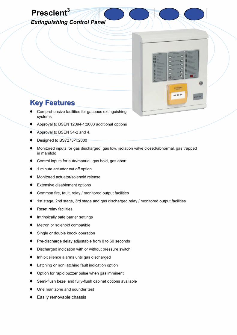
Prescient3 Extinguishing Control Panel
Key FeaturesKey Features
♦ Comprehensive facilities for gaseous extinguishing systems
♦ Approval to BSEN 12094-1:2003 additional options
♦ Approval to BSEN 54-2 and 4.
♦ Designed to BS7273-1:2000
♦ Monitored inputs for gas discharged, gas low, isolation valve closed/abnormal, gas trapped in manifold
♦ Control inputs for auto/manual, gas hold, gas abort
♦ 1 minute actuator cut off option
♦ Monitored actuator/solenoid release
♦ Extensive disablement options
♦ Common fire, fault, relay / monitored output facilities
♦ 1st stage, 2nd stage, 3rd stage and gas discharged relay / monitored output facilities
♦ Reset relay facilities
♦ Intrinsically safe barrier settings
♦ Metron or solenoid compatible
♦ Single or double knock operation
♦ Pre-discharge delay adjustable from 0 to 60 seconds
♦ Discharged indication with or without pressure switch
♦ Inhibit silence alarms until gas discharged
♦ Latching or non latching fault indication option
♦ Option for rapid buzzer pulse when gas imminent
♦ Semi-flush bezel and fully-flush cabinet options available
♦ One man zone and sounder test
♦ Easily removable chassis
From the UK's leading control panel manufacturer
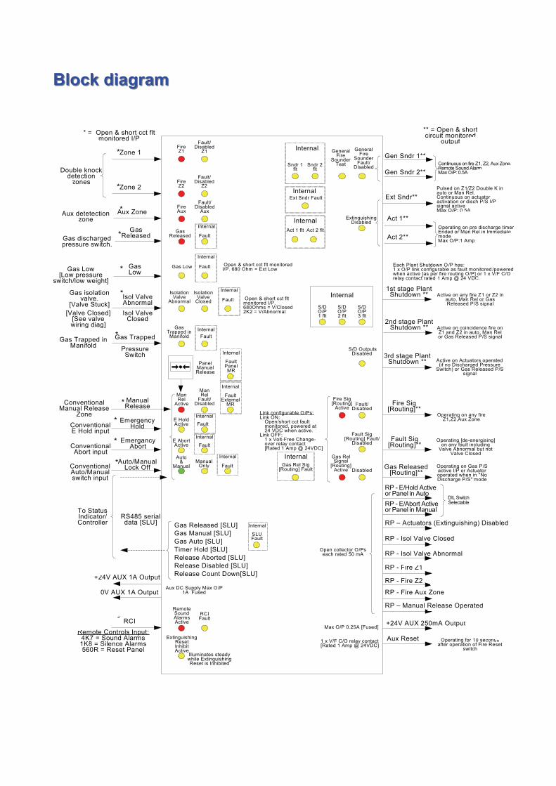
Panel OverviewPanel Overview General The Prescient3 gaseous extinguishant control panel is powerful yet user-friendly and is designed and manufactured to a high standard. The panel features approval to BSEN 12094-1:2003, BSEN 54-2 and 4 and is designed to BS7273 part 1. The panel has extensive configuration options but is easy to install, programme and operate. The removable chassis enables the engineer to “first fix” an empty cabinet and then fit the chassis at the commissioning stage. This is supported by comprehensive documentation on commissioning, operating, maintenance and fault finding. In addition there is a comprehensive range of compatible accessories available to meet most customer requirements. Operation Three fully-monitored detection zones are provided. Zones 1 and 2 normally provide first stage and second stage fire conditions to allow extinguishant discharge (coincidence detection zones). Zone 3 is an auxiliary zone for detection only purposes. Zone 4 is used as a manual release zone. Facilities Three fully-monitored alarm circuits are provided, each rated at 0.5A with various configuration options via the engineers’ DIL switch settings. Two circuits are designed to provide audible warning of any fire condition and one circuit to provide an individually distinct audible warnings of the of pre-discharge, discharged and emergency hold condition. Two fully-monitored actuator/solenoid circuits, each rated at 1A, operate simultaneously upon “extinguishant release”. An RS485 multi-drop circuit link supports up to 7 Status Controller/Indicators of either type [basic or fully functional] mixed on the communication path. Additional terminals and configuration options allows the engineer to configure the manual release, abort and hold switches to either data comms or hard wired inputs as required. Normally-open inputs provide for remote evacuate, silence alarms, system reset, lock-off input, low pressure and gas discharged pressure switch input. Outputs are provided for first stage signalling, second stage signalling, system Discharged, common fire and common fault . These outputs may be configured as either VF C/O contacts or monitored 24V (50mA) outputs. A system reset VF relay is also provided. Configuration The use of DIL switches on the internal motherboard enables the engineer to easily configure the extensive options available and view the panel’s configuration upon any return visit. The DIL switch functions are listed in the technical specification of this leaflet.
Zone 1
Zone 2
Aux Zone
Gas Released
Gas Low
Isol Valve AbnormalIsol Valve
Closed
Act 1**
Act 2**
Gen Sndr 1**
Gen Sndr 2**
Ext Sndr**
Gas Released [Routing]**
Gas Released [SLU]Gas Manual [SLU]Gas Auto [SLU]
1st stage Plant Shutdown **
Fire Sig [Routing]**
Fault Sig [Routing]**
Timer Hold [SLU]Release Aborted [SLU]
+24V AUX 1A Output
2nd stage Plant Shutdown **
Aux Reset
Double knock detection
zones
Aux detetection zone
PanelManualRelease
Gas discharged pressure switch.
Gas Low[Low pressure
switch/low weight]
[Valve Closed][See valvewiring diag]
Gas isolationvalve.
[Valve Stuck]
Fire Z1
Fault/Disabled
Z1
Fire Z2
Fault/Disabled
Z2
Fire Aux
Fault/Disabled
Aux
Gas Released Fault
Gas Low
* = Open & short cct flt monitored I/P
*
*
*
Open & short cct flt monitored I/P. 680 Ohm = Ext Low
Open & short cct flt monitored I/P. 680Ohms = V/Closed2K2 = V/Abnormal
General Fire
Sounder Test
General Fire
Sounder Fault/
DisabledSndr 1 flt
Sndr 2 flt
Internal
Act 1 flt Act 2 flt
Internal Extinguishing Disabled
Aux DC Supply Max O/P1A Fused
Active on any fire Z1 or Z2 in auto, Man Rel or Gas Released P/S signal
Pulsed on Z1/Z2 Double K in auto or Man Rel.Continuous on actuator activation or disch P/S I/P signal activeMax O/P: 0.5A
** = Open & short circuit monitored
output
Active on coincidence fire on Z1 and Z2 in auto, Man Rel or Gas Released P/S signal
Fire Sig [Routing]
ActiveFault/
Disabled
Fault Sig[Routing] Fault/
Disabled
S/D Outputs Disabled
Gas Rel Signal
[Routing] Active Disabled
Operating on any fire Z1,Z2,Aux Zone
Link configurable O/Ps:Link ON:
Open/short cct fault monitored, powered at 24 VDC when active.
Link OFF:1 x Volt-Free Change-over relay contact[Rated 1 Amp @ 24VDC]
Operating [de-energising] on any fault including
Valve Abnormal but not Valve Closed
Operating on Gas P/S active I/P or Actuator operated when in "No Discharge P/S" mode
Open collector O/Ps each rated 50 mA
1 x V/F C/O relay contact [Rated 1 Amp @ 24VDC]
Operating for 10 seconds after operation of Fire Reset
switch
*
*
*
3rd stage Plant Shutdown ** Active on Actuators operated
(if no Discharged Pressure Switch) or Gas Released P/S
signal
Each Plant Shutdown O/P has:1 x O/P link configurable as fault monitored /powered when active [as per fire routing O/P] or 1 x V/F C/O relay contact rated 1 Amp @ 24 VDC.
S/DO/P1 flt
Internal
S/DO/P2 flt
S/DO/P3 flt
Gas Trapped
Pressure Switch
Gas Trapped in Manifold
+24V AUX 250mA OutputMax O/P 0.25A [Fused]
InternalExt Sndr Fault
Release Disabled [SLU]
RP - E/Hold Active or Panel in AutoRP - E/Abort Active or Panel in Manual
RP - Isol Valve Closed
RP - Isol Valve Abnormal
RP – Actuators (Extinguishing) Disabled
Internal
Fault
Internal
Auto&
ManualManual
Only Fault
Internal
E Abort Active Fault
Internal
E Hold Active Fault
Internal
IsolationValve
Abnormal
Isolation Valve
Closed Fault
Internal
Gas Trapped in Manifold Fault
Internal
0V AUX 1A Output
Release Count Down[SLU]
RS485 serial data [SLU]
To Status Indicator/Controller
SLUFault
Internal
Man Rel
Active
ManRel
Fault/Disabled
InternalGas Rel Sig
[Routing] Fault
ConventionalManual Release
Zone
Manual Release
ConventionalE Hold input
Emergency Hold
ConventionalAbort input
Emergancy Abort
*
*
*
*
ConventionalAuto/Manualswitch input
Auto/ManualLock Off
*
RCIRemote Controls Input:
4K7 = Sound Alarms1K8 = Silence Alarms560R = Reset Panel
Remote Sound AlarmsActive
RCIFault*
RP - Fire Z1
RP - Fire Z2
RP - Fire Aux Zone
RP – Manual Release Operated
DIL Switch Selectable
Continuous on fire Z1, Z2, Aux Zone,Remote Sound AlarmMax O/P: 0.5A
Operating on pre discharge timerEnded or Man Rel in ImmediatemodeMax O/P:1 Amp
Internal
FaultPanel MR
Internal
FaultExternal
MR
ExtinguishingResetInhibitActive
Illuminates steady while Extinguishing Reset is Inhibited
Block diagramBlock diagram
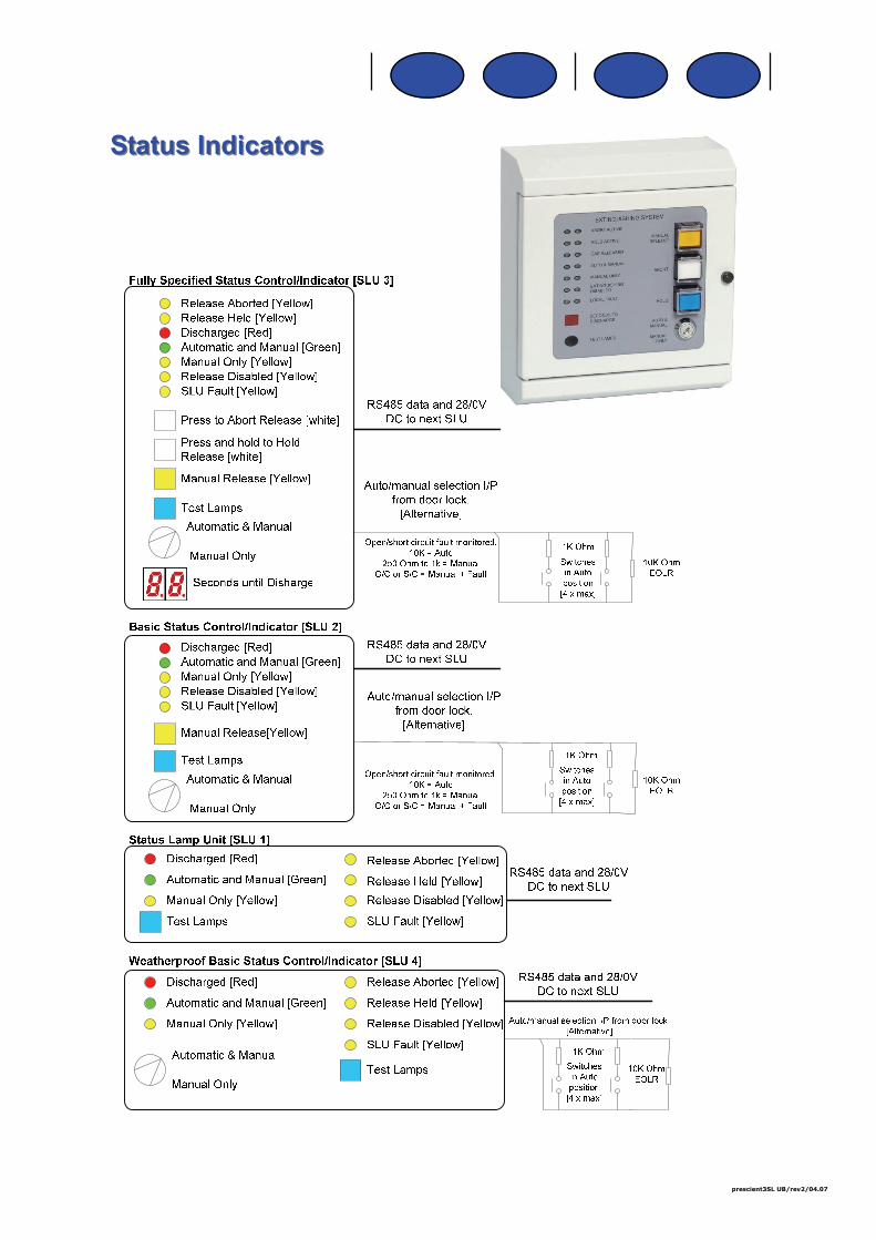
Status IndicatorsStatus Indicators
prescient3SL UB/rev2/04.07