Embed Size (px)
Citation preview
Retrofit Engineering for Steel Bridge Structures in Japan
Takuyo KonishiVisiting Associate Professor of CivilEngineering, Tokyo Institute of Technol-ogy, Tokyo , J apan , k o n [email protected]
Chitoshi Miki, bornin1947, receive civilengineering doctordegree from the To-kyo Institute of Tech-nology. Currently avice president for ed-ucation.
Chitishi MikiProfessor of Civil Engineering, TokyoInstitute of Technology, Tokyo, Japan,[email protected]
Takuyo Konishi, bornin 1960, receive civilengineering doctordegree from the To-kyo Institute of Tech-nology.
SummaryThe cases of fatigue damage, repair and retrofit applied are presented. The causes of fatigue damageare categorized as follows. (a) welding defects were remained during fabrication, (b) inappropriatestructural details of low fatigue strength were adopted, (c) stresses and deformations unforeseen indesign occurred at joints of members (d) structures behavior in a manner not expected, such as vibra-tion due to wind. Case studies include girder bridges, orthotropic steel bridge decks, steel bridge pierstructures and others.
Keywords: fatigue, retrofit, repair, improvement
1. IntroductionA number of steel bridges have been suffering fatigue cracking which sometimes resulted in brittlefracture since sixties of the last century. The occurrences of these accidents have been increasingmore and more. How to manage fatigue related problems have been important and urgent assign-ment to bridge engineers. Since elements of the social infrastructure are constructed in order of demand, major roads and raillines were provided first. In other words, the greater the importance of the line under bridges arebuilt, the earlier the technology used to built it, moreover, the bridges are likely to be subject togreater loads. These are vital data from the view point of bridge maintenance, particularly, fatigueand fracture control of steel bridges, and bridge engineers involved in the maintenance of bridgesmust be aware of them. This paper introduces the cases of fatigue damage, the repair and retrofit methods applied. Becausethe causes of failures and repair measures for the cases are often referred from the repair casesreported in the past, it is very useful to obtain knowledge from the past case studies and it is expectedthat such accumulated information will be of use in the maintenance technology. The causes of these are widely varied, relating with design construction and maintenance. Thecauses of fatigue of steel bridges may be categorized as follows:
(a) Welding defects were included at the time of fabrication.
(b) An inappropriate structural detail of low fatigue strength had been adopted.
IABSE Symposium, Weimar 2007
(c) Stresses and deformations unforeseen in design occurred at joints of members.
(d) The structure behaved in a manner not expected, such as due to vibration.
Fatigue cracking cases of bridge structures are provided from the view point of these categories.
2. Girder Bridges
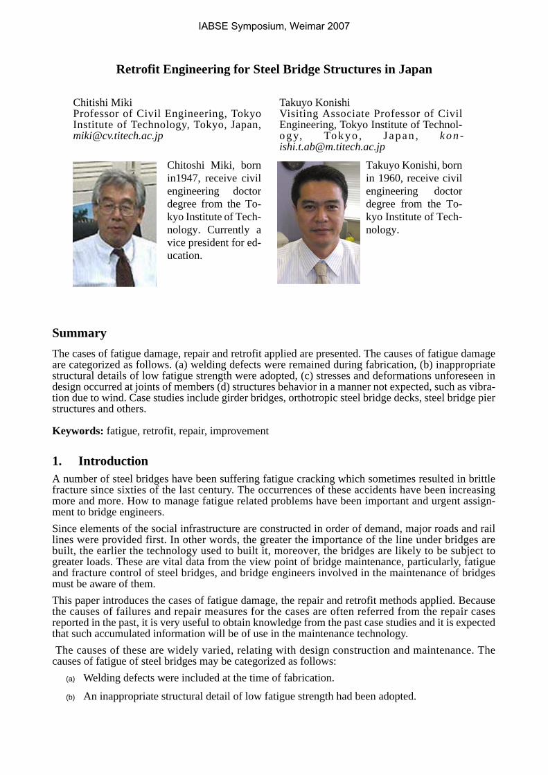
2.1 Butt welded joints in the bottom flange of plate girder; category (a)There are cases of girders failing due to fatigue cracks occurring from welding defects unintention-ally fabricated in the welds of the plate joints at the bottom flanges of plate girders. Normally, such ajoint is subjected to X-ray inspection after welding so that occurrences of damage are rare. A fatiguecrack, after propagating through the bottom flange, passes the fillet weld between the flange and weband penetrates to the web. Brittle failure will occur in the event the fracture toughness of the steel islow. Fig. 1is a case of a bottom flange failing due to insufficient penetration of a butt weld [13].There are also cases reported of cracking of welds being a cause besides lack of penetration [12]. Such structural details would be no problem at all if there were no defects, and it may be said that itwould suffice to perform welding so that a joint with sound quality is again obtained. However, thiswelding would be done in the field, and in many cases it will be difficult to secure working condi-tions under which sound welded joints can be obtained. There are also many cases in which brittlefracture has gone through the web and has stopped immediately under the top flange. If welding isapplied for repairing, there are many problems such as removal of cracks, groove preparation, orhandling of the start-restart part of welding. Consequently, in such cases, distortion due to cracking isremoved by a method such as jack-up, after which repair is done by splicing using high-strengthbolts [12](Fig. 2).
Fig. 1 Fatigue Crack propagating in girder Flange
Fig. 2 Retrofit Detail for flange crack
Weld Crack
Lower Flange
FillerPLAdd.Splice PL
Web
IABSE Symposium, Weimar 2007
It is close to impossible to predict the appearance of fatigue damage caused by a defect. However,after a single case has occurred, it is possible to take measures such as intensive inspection of jointsmade in the same factory around the same time using the same welding details. In the case of Fig. 1,as a result of inspecting butt welds made in the same factory for the same bridge, a large number ofincomplete penetration defects were discovered.
2.2 Sole Plate at Girder End; category (b)
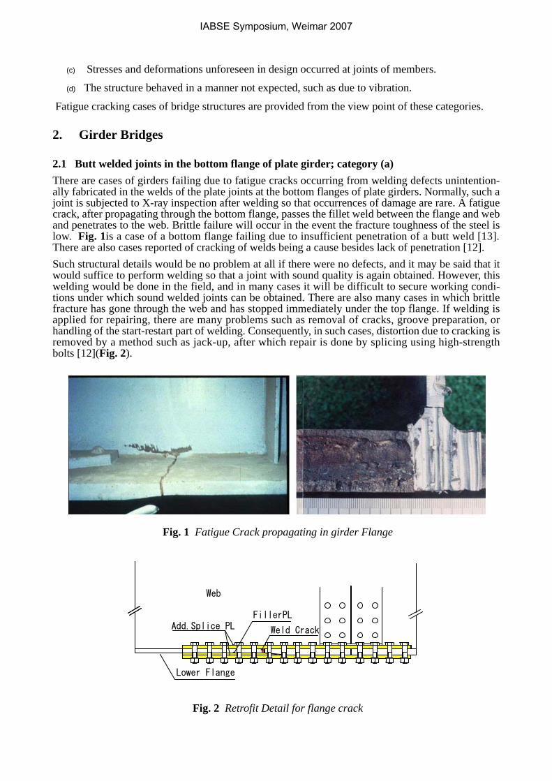
Support points on a bridge may be said to be points of the greatest force concentrations on thebridge. Beam theory is normally employed in designing a bridge, but when configuration and sizesof girders and locations of supporting points are considered, the stresses occurring near supportpoints differ considerably from those obtained by beam theory. Consequently, the regions around ofsupporting points are susceptible to fatigue damage.Fig. 3 shows fatigue cracking which occurred in a plate girder bridge where a sole plate was attachedto the underside of a bottom flange by fillet welding [21]. For sole plates, when rotating function islost, very high stresses occur at the front surface of the sole plate, and this local stress is made evenhigher by the deformation of the flange when the flange of the main girder and web are welded,
Fig. 3 Fatigue Crack From Sole Plate Fillet Weld
An example of retrofit is shown in Fig. 3. The sole plate was changed to a longer one. Joining withthe bottom flange was done using high-strength bolts. As the cracks had penetrated into the web,holes were drilled at the tips along with which splicing was done using high-strength bolts. The holesat the tips of cracks were also fastened with high-strength bolts. When cracks of webs are large,welding may also be done.
2.3 Cut out web of Girders; category (b)Fig. 4 shows fatigue cracking which occurred where a cut-out had been made at the end of a girderof a plate girder bridge. Regarding this part, bending stress is extremely small according to the beamtheory, but since a cut-out is provided, a high stress component is produced in the normal-line direc-tion at the corner of the curved part. This stress component becomes higher the smaller the curvatureratio of the curve. Since the flange and the web are joined by fillet welding, when looked at locally,this fillet weld is supposed to transmit load. Fatigue cracks often are initiated from the roots of weldsbecause of this.
(a) Fatigue Crack (b) Retrofit detail
IABSE Symposium, Weimar 2007
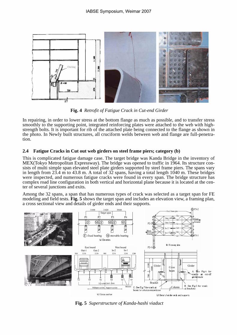
Fig. 4 Retrofit of Fatigue Crack in Cut-end Girder
In repairing, in order to lower stress at the bottom flange as much as possible, and to transfer stresssmoothly to the supporting point, integrated reinforcing plates were attached to the web with high-strength bolts. It is important for rib of the attached plate being connected to the flange as shown inthe photo. In Newly built structures, all cruciform welds between web and flange are full-penetra-tion.
2.4 Fatigue Cracks in Cut out web girders on steel frame piers; category (b)This is complicated fatigue damage case. The target bridge was Kanda Bridge in the inventory ofMEX(Tokyo Metropolitan Expressway). The bridge was opened to traffic in 1964. Its structure con-sists of multi simple span elevated steel plate girders supported by steel frame piers. The spans varyin length from 23.4 m to 43.8 m. A total of 32 spans, having a total length 1040 m. These bridgeswere inspected, and numerous fatigue cracks were found in every span. The bridge structure hascomplex road line configuration in both vertical and horizontal plane because it is located at the cen-ter of several junctions and exits.Among the 32 spans, a span that has numerous types of crack was selected as a target span for FEmodeling and field tests. Fig. 5 shows the target span and includes an elevation view, a framing plan,a cross sectional view and details of girder ends and their supports.
Fig. 5 Superstructure of Kanda-hashi viaduct
IABSE Symposium, Weimar 2007
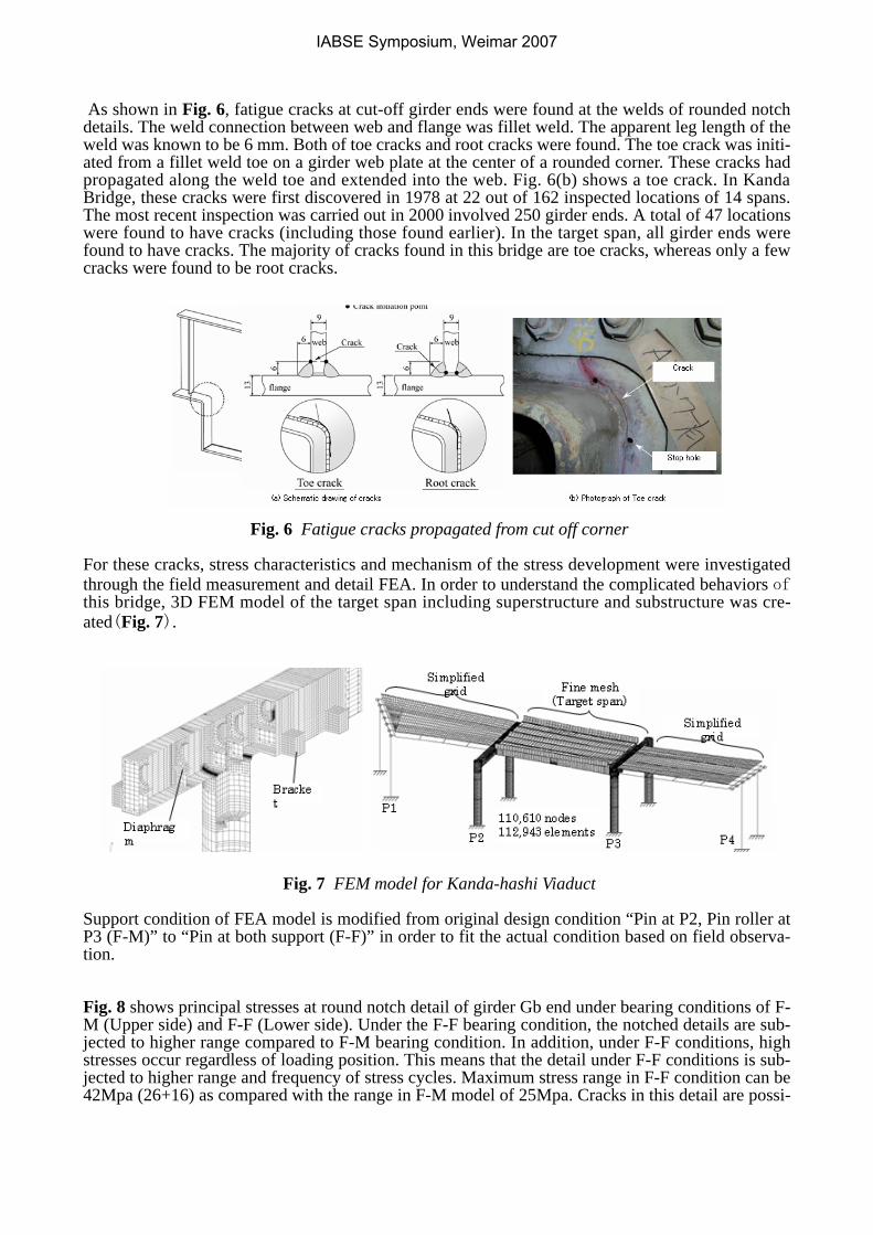
As shown in Fig. 6, fatigue cracks at cut-off girder ends were found at the welds of rounded notchdetails. The weld connection between web and flange was fillet weld. The apparent leg length of theweld was known to be 6 mm. Both of toe cracks and root cracks were found. The toe crack was initi-ated from a fillet weld toe on a girder web plate at the center of a rounded corner. These cracks hadpropagated along the weld toe and extended into the web. Fig. 6(b) shows a toe crack. In KandaBridge, these cracks were first discovered in 1978 at 22 out of 162 inspected locations of 14 spans.The most recent inspection was carried out in 2000 involved 250 girder ends. A total of 47 locationswere found to have cracks (including those found earlier). In the target span, all girder ends werefound to have cracks. The majority of cracks found in this bridge are toe cracks, whereas only a fewcracks were found to be root cracks.
Fig. 6 Fatigue cracks propagated from cut off corner
For these cracks, stress characteristics and mechanism of the stress development were investigatedthrough the field measurement and detail FEA. In order to understand the complicated behaviors ofthis bridge, 3D FEM model of the target span including superstructure and substructure was cre-ated(Fig. 7).
Fig. 7 FEM model for Kanda-hashi Viaduct
Support condition of FEA model is modified from original design condition “Pin at P2, Pin roller atP3 (F-M)” to “Pin at both support (F-F)” in order to fit the actual condition based on field observa-tion. Fig. 8 shows principal stresses at round notch detail of girder Gb end under bearing conditions of F-M (Upper side) and F-F (Lower side). Under the F-F bearing condition, the notched details are sub-jected to higher range compared to F-M bearing condition. In addition, under F-F conditions, highstresses occur regardless of loading position. This means that the detail under F-F conditions is sub-jected to higher range and frequency of stress cycles. Maximum stress range in F-F condition can be42Mpa (26+16) as compared with the range in F-M model of 25Mpa. Cracks in this detail are possi-
IABSE Symposium, Weimar 2007
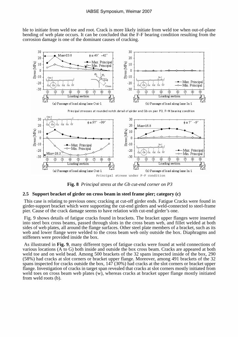
ble to initiate from weld toe and root. Crack is more likely initiate from weld toe when out-of-planebending of web plate occurs. It can be concluded that the F-F bearing condition resulting from thecorrosion damage is one of the dominant causes of cracking.
Fig. 8 Principal stress at the Gb cut-end corner on P3
2.5 Support bracket of girder on cross beam in steel frame pier; category (c) This case is relating to previous ones; cracking at cut-off girder ends. Fatigue Cracks were found ingirder-support bracket which were supporting the cut-end girders and weld-connected to steel-framepier. Cause of the crack damage seems to have relation with cut-end girder’s one. Fig. 9 shows details of fatigue cracks found in brackets. The bracket upper flanges were insertedinto steel box cross beams, passed through slots in the cross beam web, and fillet welded at bothsides of web plates, all around the flange surfaces. Other steel plate members of a bracket, such as itsweb and lower flange were welded to the cross beam web only outside the box. Diaphragms andstiffeners were provided inside the box. As illustrated in Fig. 9, many different types of fatigue cracks were found at weld connections ofvarious locations (A to G) both inside and outside the box cross beam. Cracks are appeared at bothweld toe and on weld bead. Among 500 brackets of the 32 spans inspected inside of the box, 290(58%) had cracks at slot corners or bracket upper flange. Moreover, among 491 brackets of the 32spans inspected for cracks outside the box, 147 (30%) had cracks at the slot corners or bracket upperflange. Investigation of cracks in target span revealed that cracks at slot corners mostly initiated fromweld toes on cross beam web plates (w), whereas cracks at bracket upper flange mostly initiatedfrom weld roots (b).
Principal stress under F-F condition
IABSE Symposium, Weimar 2007
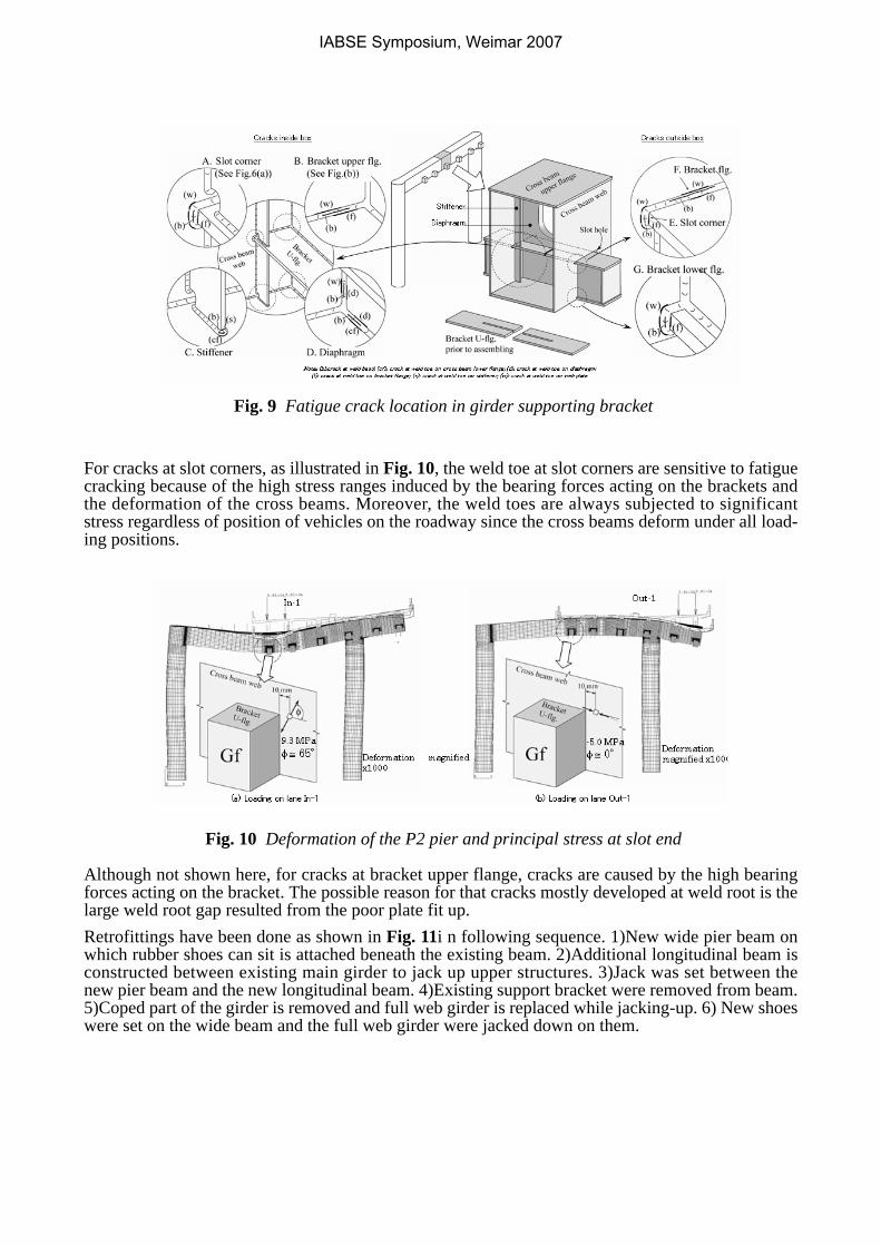
Fig. 9 Fatigue crack location in girder supporting bracket
For cracks at slot corners, as illustrated in Fig. 10, the weld toe at slot corners are sensitive to fatiguecracking because of the high stress ranges induced by the bearing forces acting on the brackets andthe deformation of the cross beams. Moreover, the weld toes are always subjected to significantstress regardless of position of vehicles on the roadway since the cross beams deform under all load-ing positions.
Fig. 10 Deformation of the P2 pier and principal stress at slot end
Although not shown here, for cracks at bracket upper flange, cracks are caused by the high bearingforces acting on the bracket. The possible reason for that cracks mostly developed at weld root is thelarge weld root gap resulted from the poor plate fit up.Retrofittings have been done as shown in Fig. 11i n following sequence. 1)New wide pier beam onwhich rubber shoes can sit is attached beneath the existing beam. 2)Additional longitudinal beam isconstructed between existing main girder to jack up upper structures. 3)Jack was set between thenew pier beam and the new longitudinal beam. 4)Existing support bracket were removed from beam.5)Coped part of the girder is removed and full web girder is replaced while jacking-up. 6) New shoeswere set on the wide beam and the full web girder were jacked down on them.
IABSE Symposium, Weimar 2007
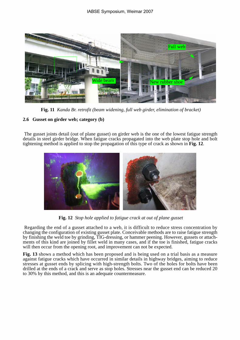
Fig. 11 Kanda Br. retrofit (beam widening, full web girder, elimination of bracket)
2.6 Gusset on girder web; category (b)
The gusset joints detail (out of plane gusset) on girder web is the one of the lowest fatigue strengthdetails in steel girder bridge. When fatigue cracks propagated into the web plate stop hole and bolttightening method is applied to stop the propagation of this type of crack as shown in Fig. 12.
Fig. 12 Stop hole applied to fatigue crack at out of plane gusset
Regarding the end of a gusset attached to a web, it is difficult to reduce stress concentration bychanging the configuration of existing gusset plate. Conceivable methods are to raise fatigue strengthby finishing the weld toe by grinding, TIG-dressing, or hammer peening. However, gussets or attach-ments of this kind are joined by fillet weld in many cases, and if the toe is finished, fatigue crackswill then occur from the opening root, and improvement can not be expected.Fig. 13 shows a method which has been proposed and is being used on a trial basis as a measureagainst fatigue cracks which have occurred in similar details in highway bridges, aiming to reducestresses at gusset ends by splicing with high-strength bolts. Two of the holes for bolts have beendrilled at the ends of a crack and serve as stop holes. Stresses near the gusset end can be reduced 20to 30% by this method, and this is an adequate countermeasure.
Wide beam
Full web
New rubber shoe
IABSE Symposium, Weimar 2007
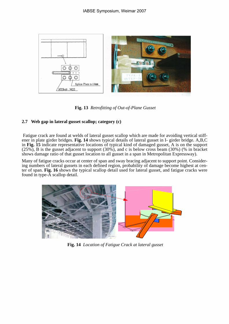
Fig. 13 Retrofitting of Out-of-Plane Gusset
2.7 Web gap in lateral gusset scallop; category (c)
Fatigue crack are found at welds of lateral gusset scallop which are made for avoiding vertical stiff-ener in plate girder bridges. Fig. 14 shows typical details of lateral gusset in I- girder bridge. A,B,Cin Fig. 15 indicate representative locations of typical kind of damaged gusset, A is on the support(25%), B is the gusset adjacent to support (30%), and c is below cross beam (30%) (% in bracketshows damage ratio of that gusset location to all gusset in a span in Metropolitan Expressway). Many of fatigue cracks occur at center of span and sway bracing adjacent to support point. Consider-ing numbers of lateral gussets in each defined region, probability of damage become highest at cen-ter of span. Fig. 16 shows the typical scallop detail used for lateral gusset, and fatigue cracks werefound in type-A scallop detail.
Fig. 14 Location of Fatigue Crack at lateral gusset
IABSE Symposium, Weimar 2007
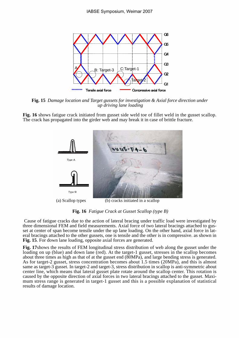
Fig. 15 Damage location and Target gussets for investigation & Axial force direction under up driving lane loading
Fig. 16 shows fatigue crack initiated from gusset side weld toe of fillet weld in the gusset scallop.The crack has propagated into the girder web and may break it in case of brittle fracture.
Fig. 16 Fatigue Crack at Gusset Scallop (type B)
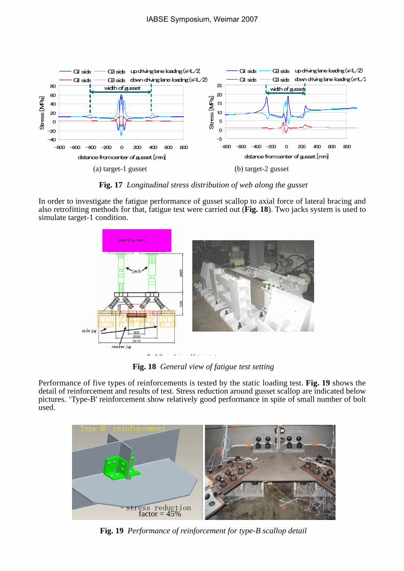
Cause of fatigue cracks due to the action of lateral bracing under traffic load were investigated bythree dimensional FEM and field measurements. Axial force of two lateral bracings attached to gus-set at center of span become tensile under the up lane loading. On the other hand, axial force in lat-eral bracings attached to the other gussets, one is tensile and the other is in compressive. as shown inFig. 15. For down lane loading, opposite axial forces are generated. Fig. 17shows the results of FEM longitudinal stress distribution of web along the gusset under theloading on up (blue) and down lane (red). At the target-1 gusset, stresses in the scallop becomesabout three times as high as that of at the gusset end (80MPa), and large bending stress is generated.As for target-2 gusset, stress concentration becomes about 1.5 times (20MPa), and this is almostsame as target-3 gusset. In target-2 and target-3, stress distribution in scallop is anti-symmetric aboutcenter line, which means that lateral gusset plate rotate around the scallop center. This rotation iscaused by the opposite direction of axial forces in two lateral bracings attached to the gusset. Maxi-mum stress range is generated in target-1 gusset and this is a possible explanation of statisticalresults of damage location.
G1
G3
G4
G2
G5
G6
Tensile axial force Compressive axial force
G1
G3
G4
G2
G5
G6
Tensile axial force Compressive axial force
C:Target-1
Target-2
B: Target-3A
(a) Scallop types (b) cracks initiated in a scallop
IABSE Symposium, Weimar 2007
(a) target-1 gusset (b) target-2 gusset
Fig. 17 Longitudinal stress distribution of web along the gusset
In order to investigate the fatigue performance of gusset scallop to axial force of lateral bracing andalso retrofitting methods for that, fatigue test were carried out (Fig. 18). Two jacks system is used tosimulate target-1 condition.
Fig. 18 General view of fatigue test setting
Performance of five types of reinforcements is tested by the static loading test. Fig. 19 shows thedetail of reinforcement and results of test. Stress reduction around gusset scallop are indicated belowpictures. ‘Type-B' reinforcement show relatively good performance in spite of small number of boltused.
Fig. 19 Performance of reinforcement for type-B scallop detail
-40
-20
0
20
40
60
80
-800 -600 -400 -200 0 200 400 600 800
distance from center of gusset [mm]
Stress
[MPa]
G1 side G3 side
G1 side G3 side
up driving lane loading (x=L/2)
down driving lane loading (x=L/2)
width of gusset
-5
0
5
10
15
20
25
-800 -600 -400 -200 0 200 400 600 800
distance from center of gusset [mm]
Stress
[MPa]
G1 side G3 side
G1 side G3 side
up driving lane loading (x=L/2)
down driving lane loading (x=L/2
width of gusset
Type-B' reinforcement
stress reductionfactor = 45%
IABSE Symposium, Weimar 2007
2.8 Intermediate diaphragms in the steel box-girder bridges; category (a) and (c)
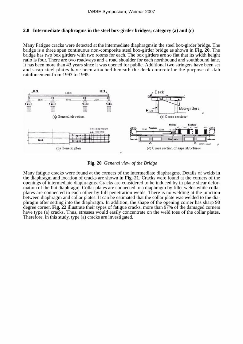
Many Fatigue cracks were detected at the intermediate diaphragmsin the steel box-girder bridge. Thebridge is a three span continuous non-composite steel box-girder bridge as shown in Fig. 20. Thebridge has two box girders with two rooms for each. The box girders are so flat that its width heightratio is four. There are two roadways and a road shoulder for each northbound and southbound lane.It has been more than 43 years since it was opened for public. Additional two stringers have been setand strap steel plates have been attached beneath the deck concretefor the purpose of slabrainforcement from 1993 to 1995.
Fig. 20 General view of the Bridge
Many fatigue cracks were found at the corners of the intermediate diaphragms. Details of welds inthe diaphragm and location of cracks are shown in Fig. 21. Cracks were found at the corners of theopenings of intermediate diaphragms. Cracks are considered to be induced by in plane shear defor-mation of the flat diaphragm. Collar plates are connected to a diaphragm by fillet welds while collarplates are connected to each other by full penetration welds. There is no welding at the junctionbetween diaphragm and collar plates. It can be estimated that the collar plate was welded to the dia-phragm after setting into the diaphragm. In addition, the shape of the opening corner has sharp 90degree corner. Fig. 22 illustrate their types of fatigue cracks, more than 97% of the damaged cornershave type (a) cracks. Thus, stresses would easily concentrate on the weld toes of the collar plates.Therefore, in this study, type (a) cracks are investigated.
IABSE Symposium, Weimar 2007
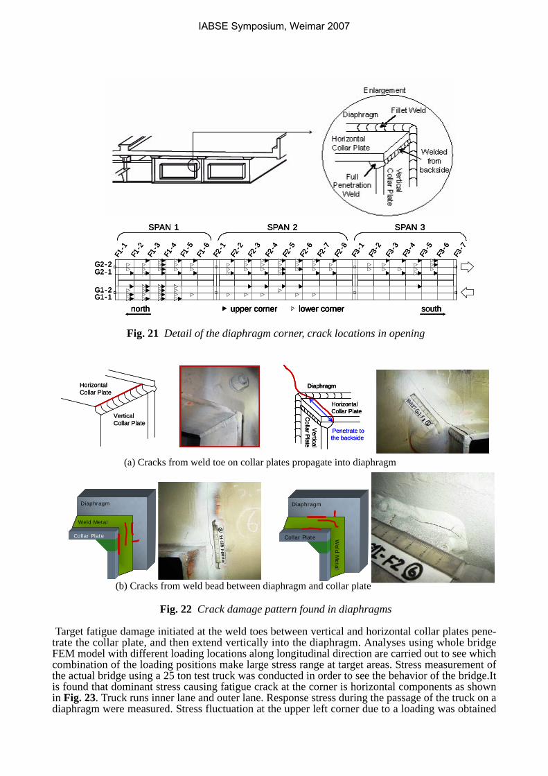
Fig. 21 Detail of the diaphragm corner, crack locations in opening
Fig. 22 Crack damage pattern found in diaphragms
Target fatigue damage initiated at the weld toes between vertical and horizontal collar plates pene-trate the collar plate, and then extend vertically into the diaphragm. Analyses using whole bridgeFEM model with different loading locations along longitudinal direction are carried out to see whichcombination of the loading positions make large stress range at target areas. Stress measurement ofthe actual bridge using a 25 ton test truck was conducted in order to see the behavior of the bridge.Itis found that dominant stress causing fatigue crack at the corner is horizontal components as shownin Fig. 23. Truck runs inner lane and outer lane. Response stress during the passage of the truck on adiaphragm were measured. Stress fluctuation at the upper left corner due to a loading was obtained
F1-1
F1-2
F1-3
F1-4
F1-5
F1-6
F2-1
F2-2
F2-3
F2-4
F2-5
F2-6
F2-7
F2-8
F3-1
F3-2
F3-3
F3-4
F3-5
F3-6
F3-7
G1-1G1-2
G2-1G2-2
SPAN 3SPAN 2SPAN 1
north southupper corner lower corner
F1-1
F1-2
F1-3
F1-4
F1-5
F1-6
F2-1
F2-2
F2-3
F2-4
F2-5
F2-6
F2-7
F2-8
F3-1
F3-2
F3-3
F3-4
F3-5
F3-6
F3-7
G1-1G1-2
G2-1G2-2
SPAN 3SPAN 2SPAN 1
north southupper corner lower corner
F1-1
F1-2
F1-3
F1-4
F1-5
F1-6
F2-1
F2-2
F2-3
F2-4
F2-5
F2-6
F2-7
F2-8
F3-1
F3-2
F3-3
F3-4
F3-5
F3-6
F3-7
G1-1G1-2
G2-1G2-2
SPAN 3SPAN 2SPAN 1
north southupper corner lower cornerupper cornerupper corner lower cornerlower corner
Vertical
Collar P
late
Diaphragm
Horizontal Collar Plate
Penetrate tothe backside
Vertical
Collar P
late
Diaphragm
Horizontal Collar Plate
Vertical
Collar P
late
Diaphragm
Horizontal Collar Plate
Penetrate tothe backside
Horizontal Collar Plate
VerticalCollar Plate
Horizontal Collar Plate
VerticalCollar Plate
(a) Cracks from weld toe on collar plates propagate into diaphragm
(b) Cracks from weld bead between diaphragm and collar plate
Diaphragm
Weld
Metal
Collar Plate
Diaphragm
Weld
Metal
Collar Plate
Diaphragm
Weld
Metal
Collar Plate
Diaphragm
Weld
Metal
Collar Plate
Diaphragm
Weld Metal
Collar Plate
Diaphragm
Weld Metal
Collar Plate
Diaphragm
Weld Metal
Collar Plate
Diaphragm
Weld Metal
Collar Plate
IABSE Symposium, Weimar 2007
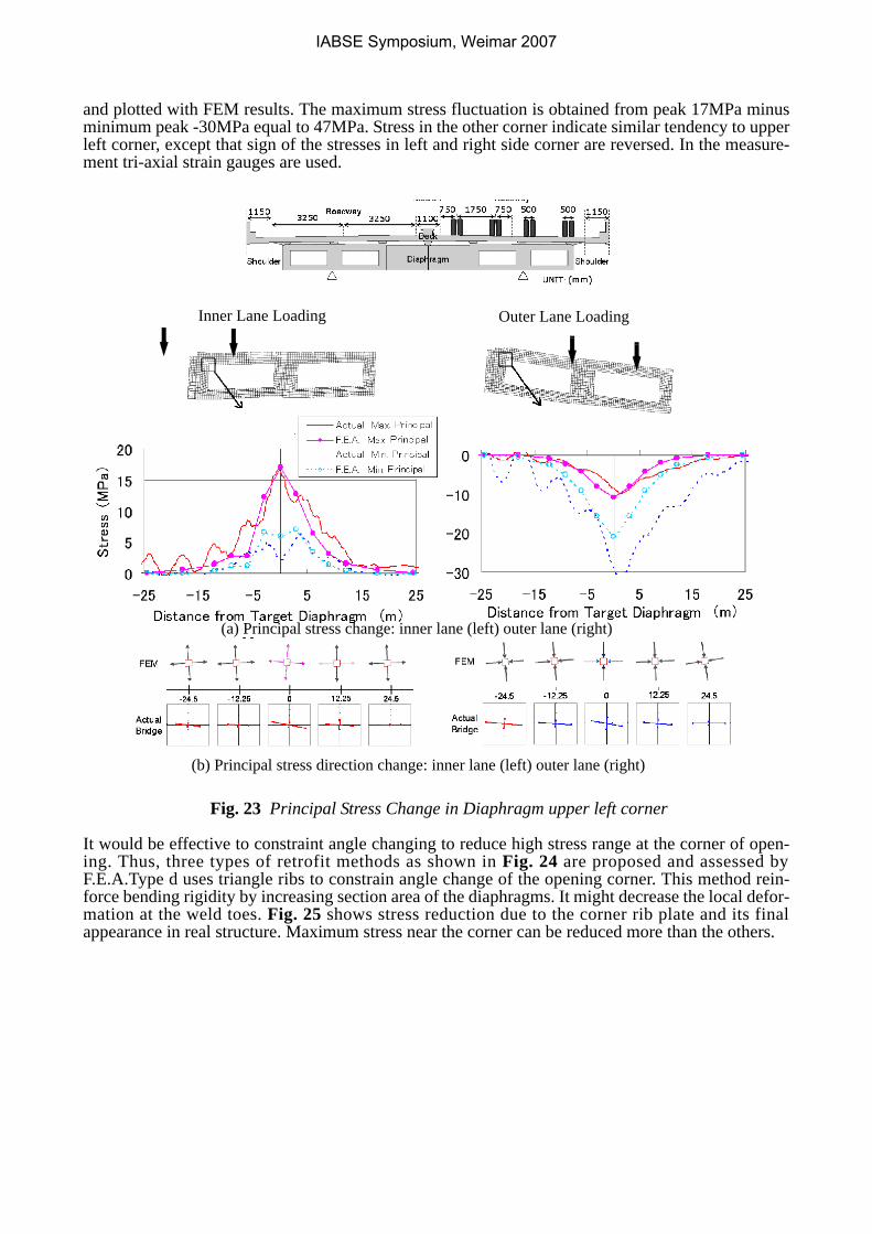
and plotted with FEM results. The maximum stress fluctuation is obtained from peak 17MPa minusminimum peak -30MPa equal to 47MPa. Stress in the other corner indicate similar tendency to upperleft corner, except that sign of the stresses in left and right side corner are reversed. In the measure-ment tri-axial strain gauges are used.
Fig. 23 Principal Stress Change in Diaphragm upper left corner
It would be effective to constraint angle changing to reduce high stress range at the corner of open-ing. Thus, three types of retrofit methods as shown in Fig. 24 are proposed and assessed byF.E.A.Type d uses triangle ribs to constrain angle change of the opening corner. This method rein-force bending rigidity by increasing section area of the diaphragms. It might decrease the local defor-mation at the weld toes. Fig. 25 shows stress reduction due to the corner rib plate and its finalappearance in real structure. Maximum stress near the corner can be reduced more than the others.
(b) Principal stress direction change: inner lane (left) outer lane (right)
Inner Lane Loading Outer Lane Loading
(a) Principal stress change: inner lane (left) outer lane (right)
IABSE Symposium, Weimar 2007
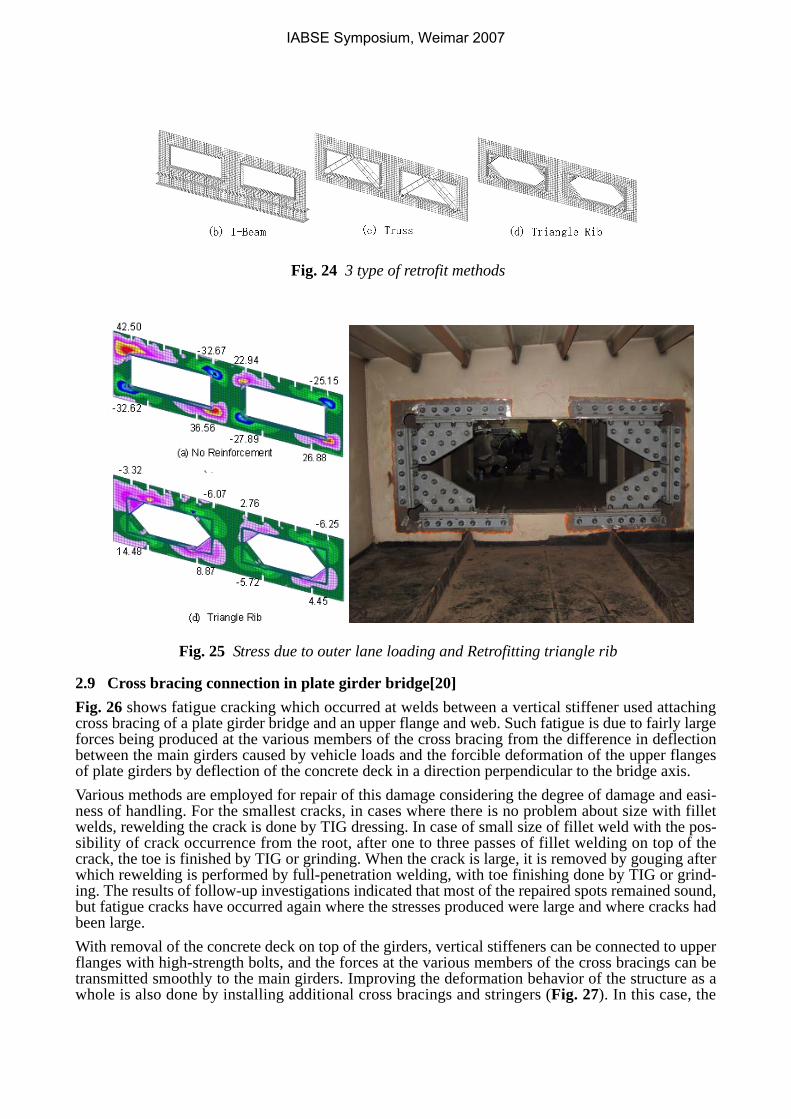
Fig. 24 3 type of retrofit methods
Fig. 25 Stress due to outer lane loading and Retrofitting triangle rib
2.9 Cross bracing connection in plate girder bridge[20]Fig. 26 shows fatigue cracking which occurred at welds between a vertical stiffener used attachingcross bracing of a plate girder bridge and an upper flange and web. Such fatigue is due to fairly largeforces being produced at the various members of the cross bracing from the difference in deflectionbetween the main girders caused by vehicle loads and the forcible deformation of the upper flangesof plate girders by deflection of the concrete deck in a direction perpendicular to the bridge axis. Various methods are employed for repair of this damage considering the degree of damage and easi-ness of handling. For the smallest cracks, in cases where there is no problem about size with filletwelds, rewelding the crack is done by TIG dressing. In case of small size of fillet weld with the pos-sibility of crack occurrence from the root, after one to three passes of fillet welding on top of thecrack, the toe is finished by TIG or grinding. When the crack is large, it is removed by gouging afterwhich rewelding is performed by full-penetration welding, with toe finishing done by TIG or grind-ing. The results of follow-up investigations indicated that most of the repaired spots remained sound,but fatigue cracks have occurred again where the stresses produced were large and where cracks hadbeen large.With removal of the concrete deck on top of the girders, vertical stiffeners can be connected to upperflanges with high-strength bolts, and the forces at the various members of the cross bracings can betransmitted smoothly to the main girders. Improving the deformation behavior of the structure as awhole is also done by installing additional cross bracings and stringers (Fig. 27). In this case, the
IABSE Symposium, Weimar 2007
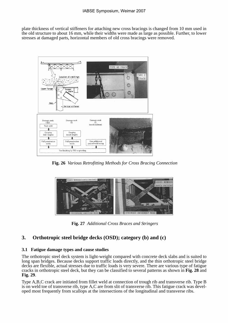
plate thickness of vertical stiffeners for attaching new cross bracings is changed from 10 mm used inthe old structure to about 16 mm, while their widths were made as large as possible. Further, to lowerstresses at damaged parts, horizontal members of old cross bracings were removed.
Fig. 26 Various Retrofitting Methods for Cross Bracing Connection
Fig. 27 Additional Cross Braces and Stringers
3. Orthotropic steel bridge decks (OSD); category (b) and (c)
3.1 Fatigue damage types and cause studiesThe orthotropic steel deck system is light-weight compared with concrete deck slabs and is suited tolong span bridges. Because decks support traffic loads directly, and the thin orthotropic steel bridgedecks are flexible, actual stresses due to traffic loads is very severe. There are various type of fatiguecracks in orthotropic steel deck, but they can be classified to several patterns as shown in Fig. 28 andFig. 29.Type A,B,C crack are initiated from fillet weld at connection of trough rib and transverse rib. Type Bis on weld toe of transverse rib, type A,C are from slit of transverse rib. This fatigue crack was devel-oped most frequently from scallops at the intersections of the longitudinal and transverse ribs.
IABSE Symposium, Weimar 2007
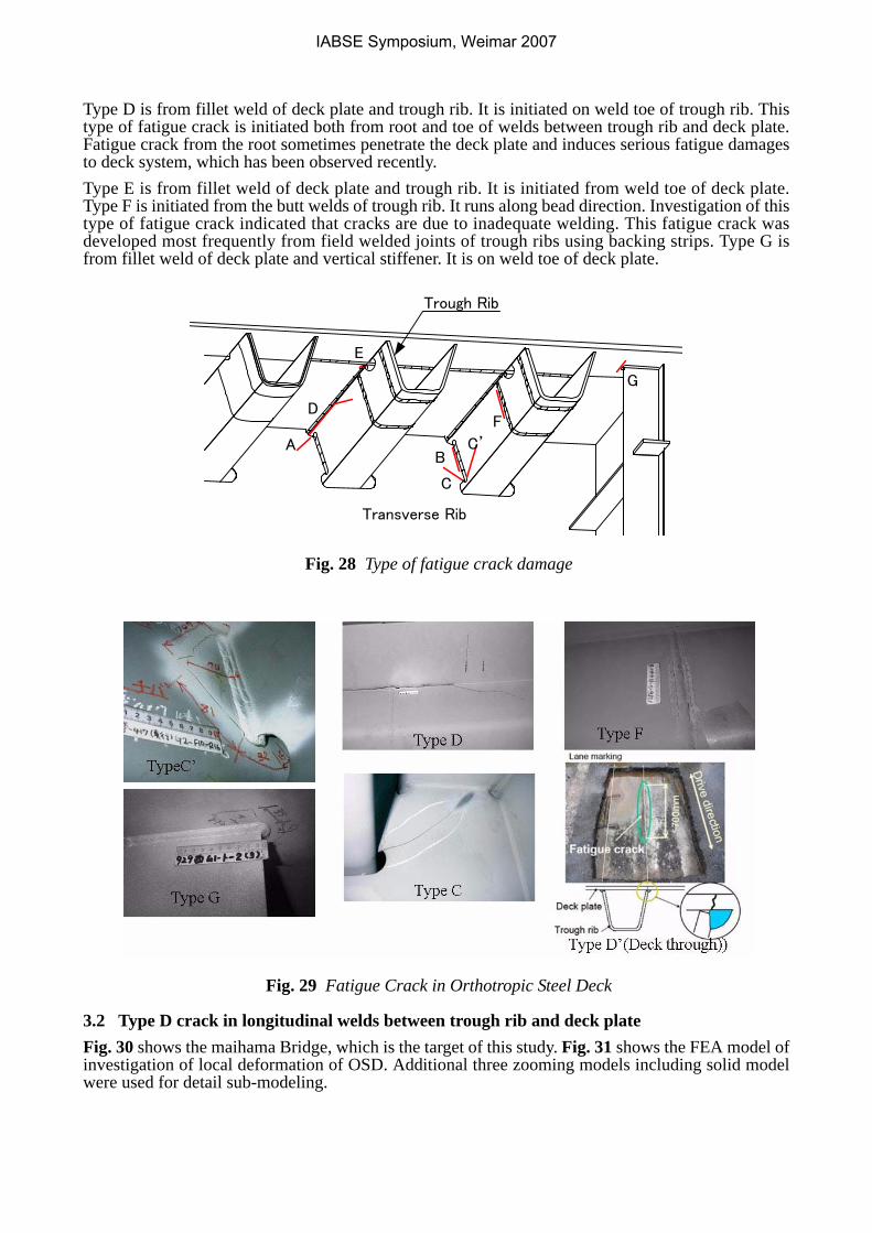
Type D is from fillet weld of deck plate and trough rib. It is initiated on weld toe of trough rib. Thistype of fatigue crack is initiated both from root and toe of welds between trough rib and deck plate.Fatigue crack from the root sometimes penetrate the deck plate and induces serious fatigue damagesto deck system, which has been observed recently.Type E is from fillet weld of deck plate and trough rib. It is initiated from weld toe of deck plate.Type F is initiated from the butt welds of trough rib. It runs along bead direction. Investigation of thistype of fatigue crack indicated that cracks are due to inadequate welding. This fatigue crack wasdeveloped most frequently from field welded joints of trough ribs using backing strips. Type G isfrom fillet weld of deck plate and vertical stiffener. It is on weld toe of deck plate.
Fig. 28 Type of fatigue crack damage
Fig. 29 Fatigue Crack in Orthotropic Steel Deck
3.2 Type D crack in longitudinal welds between trough rib and deck plate Fig. 30 shows the maihama Bridge, which is the target of this study. Fig. 31 shows the FEA model ofinvestigation of local deformation of OSD. Additional three zooming models including solid modelwere used for detail sub-modeling.
A
G
D
B
C
F
E
Transverse Rib
Trough Rib
C’
IABSE Symposium, Weimar 2007
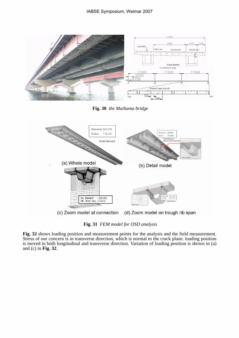
Fig. 30 the Maihama bridge
Fig. 31 FEM model for OSD analysis
Fig. 32 shows loading position and measurement points for the analysis and the field measurement.Stress of our concern is in transverse direction, which is normal to the crack plane. loading positionis moved in both longitudinal and transverse direction. Variation of loading position is shown in (a)and (c) in Fig. 32.
IABSE Symposium, Weimar 2007
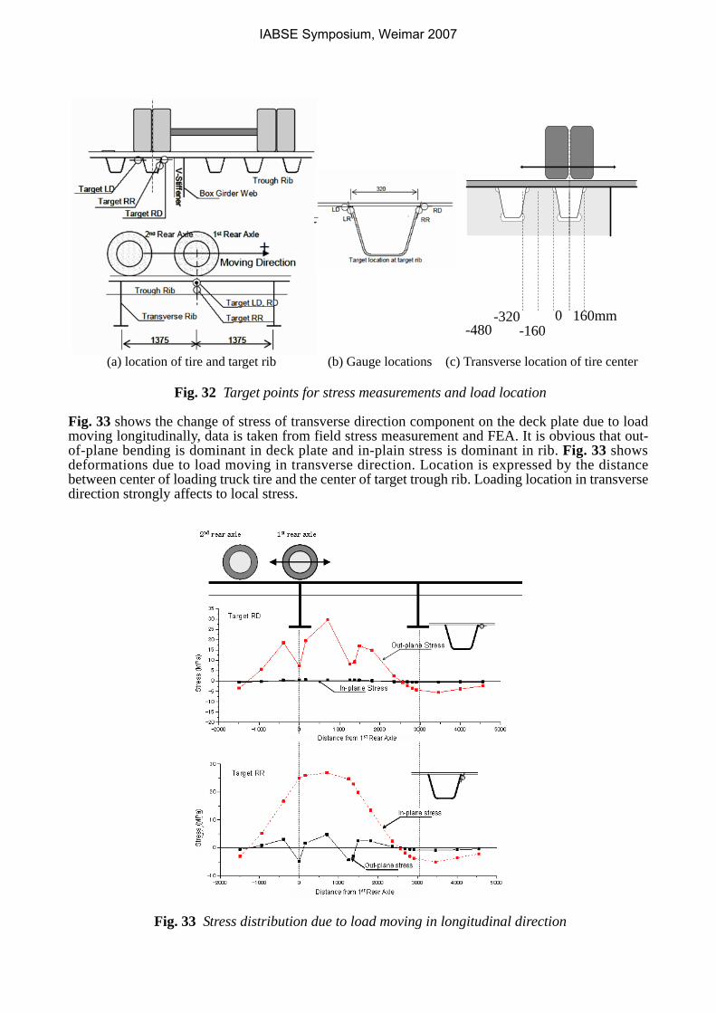
Fig. 32 Target points for stress measurements and load location
Fig. 33 shows the change of stress of transverse direction component on the deck plate due to loadmoving longitudinally, data is taken from field stress measurement and FEA. It is obvious that out-of-plane bending is dominant in deck plate and in-plain stress is dominant in rib. Fig. 33 showsdeformations due to load moving in transverse direction. Location is expressed by the distancebetween center of loading truck tire and the center of target trough rib. Loading location in transversedirection strongly affects to local stress.
Fig. 33 Stress distribution due to load moving in longitudinal direction
0 160mm-320-160-480
(c) Transverse location of tire center(b) Gauge locations(a) location of tire and target rib
IABSE Symposium, Weimar 2007
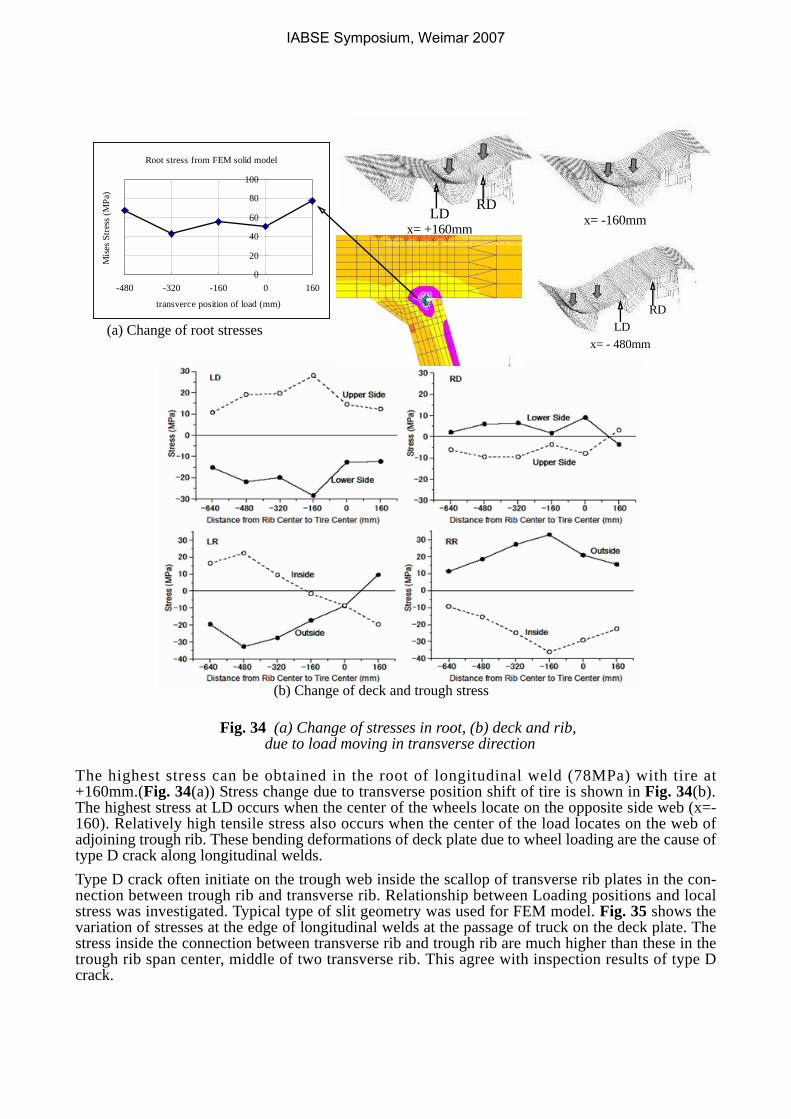
Fig. 34 (a) Change of stresses in root, (b) deck and rib, due to load moving in transverse direction
The highest stress can be obtained in the root of longitudinal weld (78MPa) with tire at+160mm.(Fig. 34(a)) Stress change due to transverse position shift of tire is shown in Fig. 34(b).The highest stress at LD occurs when the center of the wheels locate on the opposite side web (x=-160). Relatively high tensile stress also occurs when the center of the load locates on the web ofadjoining trough rib. These bending deformations of deck plate due to wheel loading are the cause oftype D crack along longitudinal welds.Type D crack often initiate on the trough web inside the scallop of transverse rib plates in the con-nection between trough rib and transverse rib. Relationship between Loading positions and localstress was investigated. Typical type of slit geometry was used for FEM model. Fig. 35 shows thevariation of stresses at the edge of longitudinal welds at the passage of truck on the deck plate. Thestress inside the connection between transverse rib and trough rib are much higher than these in thetrough rib span center, middle of two transverse rib. This agree with inspection results of type Dcrack.
x= -160mmRDLD
x= - 480mm
RDLD
Root stress from FEM solid model
0
20
40
60
80
100
-480 -320 -160 0 160
transverce position of load (mm)
Mise
s Stre
ss (M
Pa)
x= +160mm
(a) Change of root stresses
(b) Change of deck and trough stress
IABSE Symposium, Weimar 2007
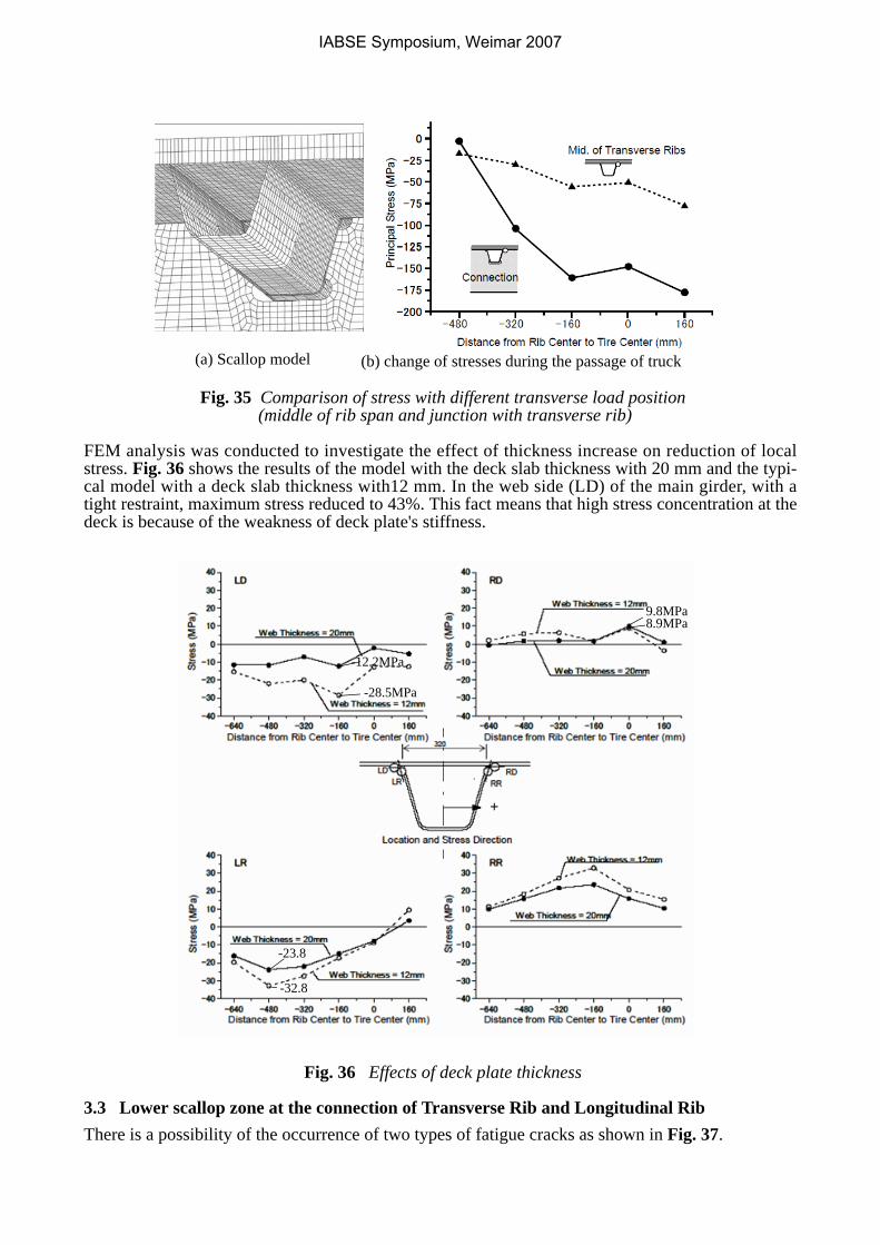
Fig. 35 Comparison of stress with different transverse load position (middle of rib span and junction with transverse rib)
FEM analysis was conducted to investigate the effect of thickness increase on reduction of localstress. Fig. 36 shows the results of the model with the deck slab thickness with 20 mm and the typi-cal model with a deck slab thickness with12 mm. In the web side (LD) of the main girder, with atight restraint, maximum stress reduced to 43%. This fact means that high stress concentration at thedeck is because of the weakness of deck plate's stiffness.
Fig. 36 Effects of deck plate thickness
3.3 Lower scallop zone at the connection of Transverse Rib and Longitudinal RibThere is a possibility of the occurrence of two types of fatigue cracks as shown in Fig. 37.
(a) Scallop model (b) change of stresses during the passage of truck
-12.2MPa
-28.5MPa
9.8MPa8.9MPa
-32.8
-23.8
+
IABSE Symposium, Weimar 2007
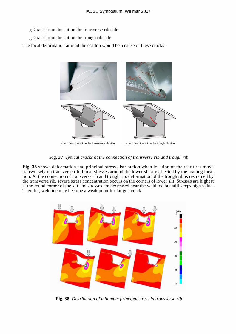
(1) Crack from the slit on the transverse rib side
(2) Crack from the slit on the trough rib side
The local deformation around the scallop would be a cause of these cracks.
Fig. 37 Typical cracks at the connection of transverse rib and trough rib
Fig. 38 shows deformation and principal stress distribution when location of the rear tires movetransversely on transverse rib. Local stresses around the lower slit are affected by the loading loca-tion. At the connection of transverse rib and trough rib, deformation of the trough rib is restrained bythe transverse rib, severe stress concentration occurs on the corners of lower slit. Stresses are highestat the round corner of the slit and stresses are decreased near the weld toe but still keeps high value.Therefor, weld toe may become a weak point for fatigue crack.
Fig. 38 Distribution of minimum principal stress in transverse rib
crack from the slit on the transverse rib side crack from the slit on the trough rib side
IABSE Symposium, Weimar 2007
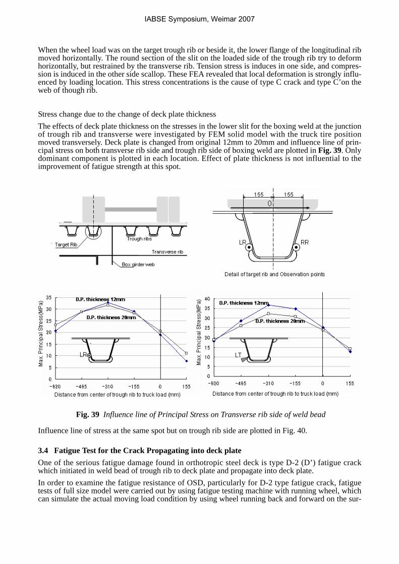
When the wheel load was on the target trough rib or beside it, the lower flange of the longitudinal ribmoved horizontally. The round section of the slit on the loaded side of the trough rib try to deformhorizontally, but restrained by the transverse rib. Tension stress is induces in one side, and compres-sion is induced in the other side scallop. These FEA revealed that local deformation is strongly influ-enced by loading location. This stress concentrations is the cause of type C crack and type C’on theweb of though rib.
Stress change due to the change of deck plate thickness The effects of deck plate thickness on the stresses in the lower slit for the boxing weld at the junctionof trough rib and transverse were investigated by FEM solid model with the truck tire positionmoved transversely. Deck plate is changed from original 12mm to 20mm and influence line of prin-cipal stress on both transverse rib side and trough rib side of boxing weld are plotted in Fig. 39. Onlydominant component is plotted in each location. Effect of plate thickness is not influential to theimprovement of fatigue strength at this spot.
Fig. 39 Influence line of Principal Stress on Transverse rib side of weld bead
Influence line of stress at the same spot but on trough rib side are plotted in Fig. 40.
3.4 Fatigue Test for the Crack Propagating into deck plateOne of the serious fatigue damage found in orthotropic steel deck is type D-2 (D’) fatigue crackwhich initiated in weld bead of trough rib to deck plate and propagate into deck plate. In order to examine the fatigue resistance of OSD, particularly for D-2 type fatigue crack, fatiguetests of full size model were carried out by using fatigue testing machine with running wheel, whichcan simulate the actual moving load condition by using wheel running back and forward on the sur-
IABSE Symposium, Weimar 2007
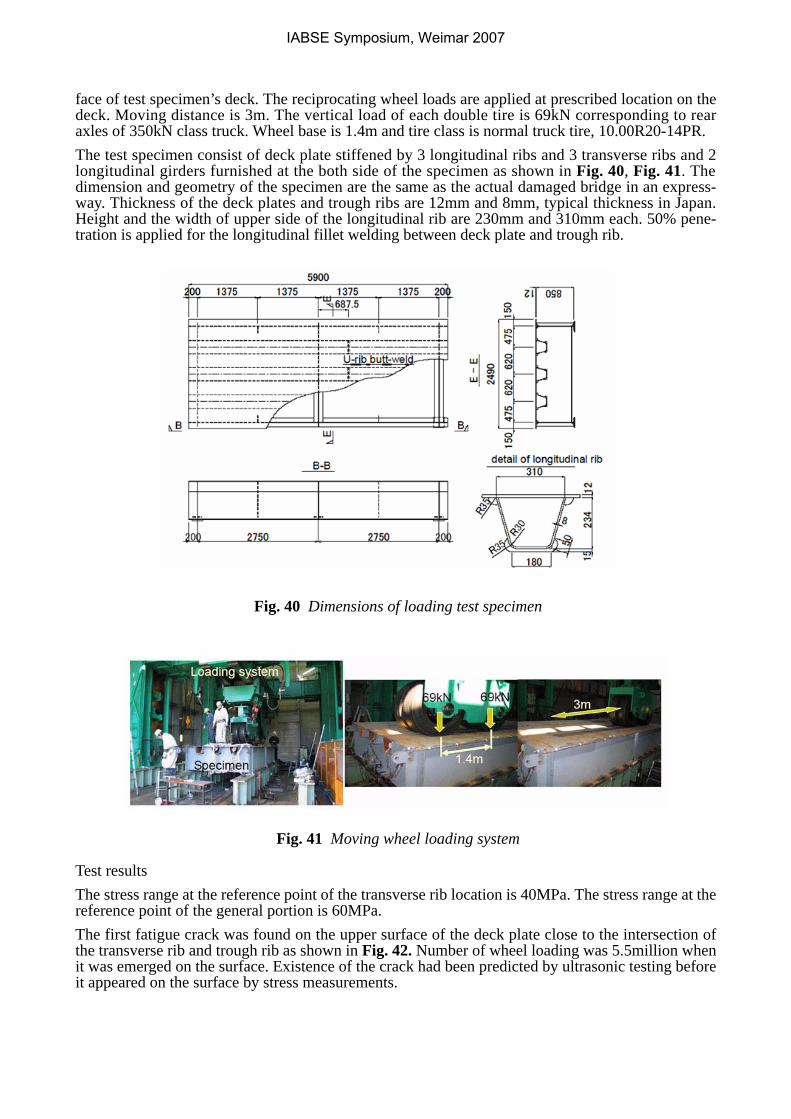
face of test specimen’s deck. The reciprocating wheel loads are applied at prescribed location on thedeck. Moving distance is 3m. The vertical load of each double tire is 69kN corresponding to rearaxles of 350kN class truck. Wheel base is 1.4m and tire class is normal truck tire, 10.00R20-14PR.The test specimen consist of deck plate stiffened by 3 longitudinal ribs and 3 transverse ribs and 2longitudinal girders furnished at the both side of the specimen as shown in Fig. 40, Fig. 41. Thedimension and geometry of the specimen are the same as the actual damaged bridge in an express-way. Thickness of the deck plates and trough ribs are 12mm and 8mm, typical thickness in Japan.Height and the width of upper side of the longitudinal rib are 230mm and 310mm each. 50% pene-tration is applied for the longitudinal fillet welding between deck plate and trough rib.
Fig. 40 Dimensions of loading test specimen
Fig. 41 Moving wheel loading system
Test resultsThe stress range at the reference point of the transverse rib location is 40MPa. The stress range at thereference point of the general portion is 60MPa.The first fatigue crack was found on the upper surface of the deck plate close to the intersection ofthe transverse rib and trough rib as shown in Fig. 42. Number of wheel loading was 5.5million whenit was emerged on the surface. Existence of the crack had been predicted by ultrasonic testing beforeit appeared on the surface by stress measurements.
IABSE Symposium, Weimar 2007
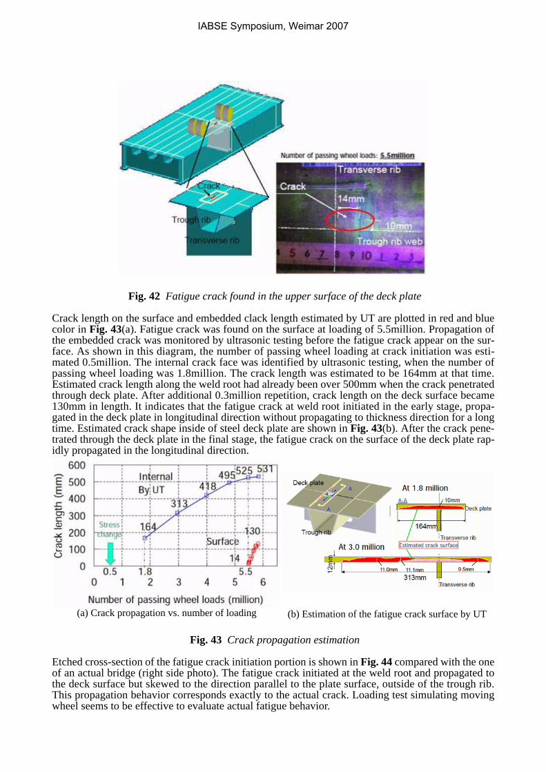
Fig. 42 Fatigue crack found in the upper surface of the deck plate
Crack length on the surface and embedded clack length estimated by UT are plotted in red and bluecolor in Fig. 43(a). Fatigue crack was found on the surface at loading of 5.5million. Propagation ofthe embedded crack was monitored by ultrasonic testing before the fatigue crack appear on the sur-face. As shown in this diagram, the number of passing wheel loading at crack initiation was esti-mated 0.5million. The internal crack face was identified by ultrasonic testing, when the number ofpassing wheel loading was 1.8million. The crack length was estimated to be 164mm at that time.Estimated crack length along the weld root had already been over 500mm when the crack penetratedthrough deck plate. After additional 0.3million repetition, crack length on the deck surface became130mm in length. It indicates that the fatigue crack at weld root initiated in the early stage, propa-gated in the deck plate in longitudinal direction without propagating to thickness direction for a longtime. Estimated crack shape inside of steel deck plate are shown in Fig. 43(b). After the crack pene-trated through the deck plate in the final stage, the fatigue crack on the surface of the deck plate rap-idly propagated in the longitudinal direction.
Fig. 43 Crack propagation estimation
Etched cross-section of the fatigue crack initiation portion is shown in Fig. 44 compared with the oneof an actual bridge (right side photo). The fatigue crack initiated at the weld root and propagated tothe deck surface but skewed to the direction parallel to the plate surface, outside of the trough rib.This propagation behavior corresponds exactly to the actual crack. Loading test simulating movingwheel seems to be effective to evaluate actual fatigue behavior.
(a) Crack propagation vs. number of loading (b) Estimation of the fatigue crack surface by UT
IABSE Symposium, Weimar 2007
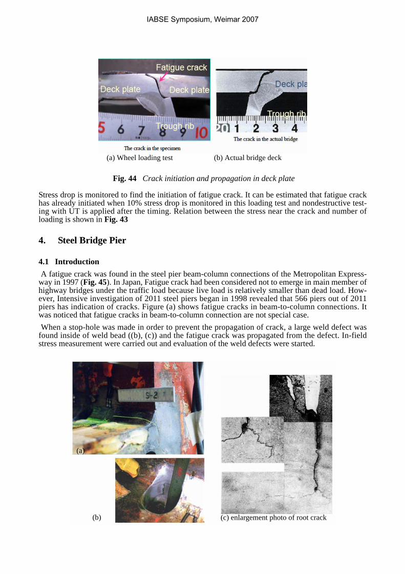
Fig. 44 Crack initiation and propagation in deck plate
Stress drop is monitored to find the initiation of fatigue crack. It can be estimated that fatigue crackhas already initiated when 10% stress drop is monitored in this loading test and nondestructive test-ing with UT is applied after the timing. Relation between the stress near the crack and number ofloading is shown in Fig. 43
4. Steel Bridge Pier
4.1 Introduction A fatigue crack was found in the steel pier beam-column connections of the Metropolitan Express-way in 1997 (Fig. 45). In Japan, Fatigue crack had been considered not to emerge in main member ofhighway bridges under the traffic load because live load is relatively smaller than dead load. How-ever, Intensive investigation of 2011 steel piers began in 1998 revealed that 566 piers out of 2011piers has indication of cracks. Figure (a) shows fatigue cracks in beam-to-column connections. Itwas noticed that fatigue cracks in beam-to-column connection are not special case. When a stop-hole was made in order to prevent the propagation of crack, a large weld defect wasfound inside of weld bead ((b), (c)) and the fatigue crack was propagated from the defect. In-fieldstress measurement were carried out and evaluation of the weld defects were started.
(a) Wheel loading test (b) Actual bridge deck
(c) enlargement photo of root crack (b)
(a)
IABSE Symposium, Weimar 2007
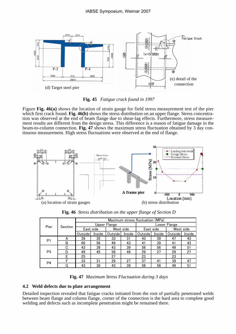
Fig. 45 Fatigue crack found in 1997
Figure Fig. 46(a) shows the location of strain gauge for field stress measurement test of the pierwhich first crack found. Fig. 46(b) shows the stress distribution on an upper flange. Stress concentra-tion was observed at the end of beam flange due to shear-lag effects. Furthermore, stress measure-ment results are different from the design stress. This difference is a reason of fatigue damage in thebeam-to-column connection. Fig. 47 shows the maximum stress fluctuation obtained by 3 day con-tinuous measurement. High stress fluctuations were observed at the end of flange.
Fig. 46 Stress distribution on the upper flange of Section D
Fig. 47 Maximum Stress Fluctuation during 3 days
4.2 Weld defects due to plate arrangementDetailed inspection revealed that fatigue cracks initiated from the root of partially penetrated weldsbetween beam flange and column flange, corner of the connection is the hard area to complete goodwelding and defects such as incomplete penetration might be remained there.
(d) Target steel pier
(e) detail of the connection
(a) location of strain gauges (b) stress distribution
Outside Inside Outside Inside Outside Inside Outside InsideA 39 35 33 31 43 39 47 43B 66 56 49 43 41 39 41 43C 43 39 43 39 56 56 49 51D 49 45 58 49 29 27 29 27E 25 27 23 23F 33 31 29 27 37 41 39 47G 43 39 43 39 56 56 49 51
Pier
P4
P3
P1
Upper Flange Lower FlangeMaximum stress fluctuation (MPa)
SectionEast side West side East side West side
IABSE Symposium, Weimar 2007
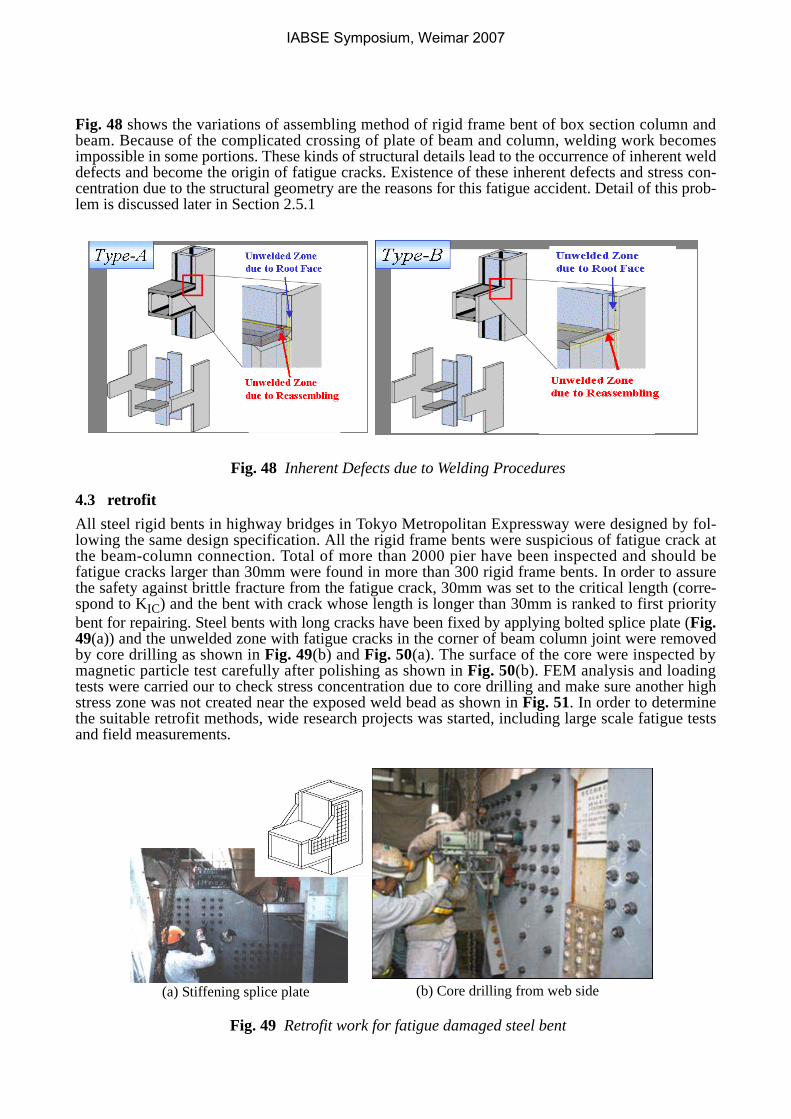
Fig. 48 shows the variations of assembling method of rigid frame bent of box section column andbeam. Because of the complicated crossing of plate of beam and column, welding work becomesimpossible in some portions. These kinds of structural details lead to the occurrence of inherent welddefects and become the origin of fatigue cracks. Existence of these inherent defects and stress con-centration due to the structural geometry are the reasons for this fatigue accident. Detail of this prob-lem is discussed later in Section 2.5.1
Fig. 48 Inherent Defects due to Welding Procedures
4.3 retrofitAll steel rigid bents in highway bridges in Tokyo Metropolitan Expressway were designed by fol-lowing the same design specification. All the rigid frame bents were suspicious of fatigue crack atthe beam-column connection. Total of more than 2000 pier have been inspected and should befatigue cracks larger than 30mm were found in more than 300 rigid frame bents. In order to assurethe safety against brittle fracture from the fatigue crack, 30mm was set to the critical length (corre-spond to KIC) and the bent with crack whose length is longer than 30mm is ranked to first prioritybent for repairing. Steel bents with long cracks have been fixed by applying bolted splice plate (Fig.49(a)) and the unwelded zone with fatigue cracks in the corner of beam column joint were removedby core drilling as shown in Fig. 49(b) and Fig. 50(a). The surface of the core were inspected bymagnetic particle test carefully after polishing as shown in Fig. 50(b). FEM analysis and loadingtests were carried our to check stress concentration due to core drilling and make sure another highstress zone was not created near the exposed weld bead as shown in Fig. 51. In order to determinethe suitable retrofit methods, wide research projects was started, including large scale fatigue testsand field measurements.
Fig. 49 Retrofit work for fatigue damaged steel bent
(a) Stiffening splice plate (b) Core drilling from web side
IABSE Symposium, Weimar 2007
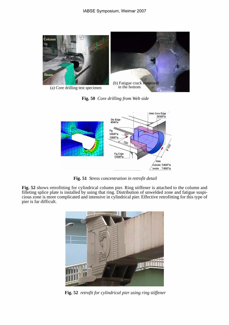
Fig. 50 Core drilling from Web side
Fig. 51 Stress concentration in retrofit detail
Fig. 52 shows retrofitting for cylindrical column pier. Ring stiffener is attached to the column andfilleting splice plate is installed by using that ring. Distribution of unwelded zone and fatigue suspi-cious zone is more complicated and intensive in cylindrical pier. Effective retrofitting for this type ofpier is far difficult.
Fig. 52 retrofit for cylindrical pier using ring stiffener
(b) Fatigue crack remained (a) Core drilling test specimen in the bottom
IABSE Symposium, Weimar 2007
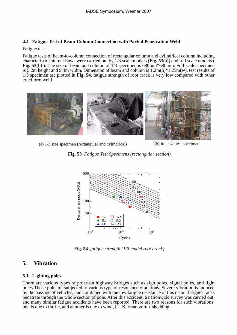
4.4 Fatigue Test of Beam-Column Connection with Partial Penetration WeldFatigue testFatigue tests of beam-to-column connection of rectangular column and cylindrical column includingcharacteristic internal flaws were carried out by 1/3 scale models (Fig. 53(a)) and full scale models (Fig. 53(b) ). The size of beam and column of 1/3 specimen is 680mm*680mm. Full-scale specimenis 5.2m height and 9.4m width. Dimension of beam and column is 1.2m(h)*1.25m(w). test results of1/3 specimen are plotted in Fig. 54. fatigue strength of root crack is very low compared with othercruciform weld.
Fig. 53 Fatigue Test Specimens (rectangular section)
Fig. 54 fatigue strength (1/3 model root crack)
5. Vibration
5.1 Lighting polesThere are various types of poles on highway bridges such as sign poles, signal poles, and lightpoles.Those pole are subjected to various type of resonance vibrations. Severe vibration is inducedby the passage of vehicles, and combined with the low fatigue resistance of this detail, fatigue crackspenetrate through the whole section of pole. After this accident, a nationwide survey was carried out,and many similar fatigue accidents have been reported. There are two reasons for such vibrations:one is due to traffic, and another is due to wind, i.e. Karman vortex shedding.
(a) 1/3 size specimen (rectangular and cylindrical) (b) full size test specimen
104 105 106
50
100
500
Des
ign
stre
ss ra
nge
(MPa
)
Cycles
A1 A2B1 B2D1 D2
5040
6380
100125
160
IABSE Symposium, Weimar 2007
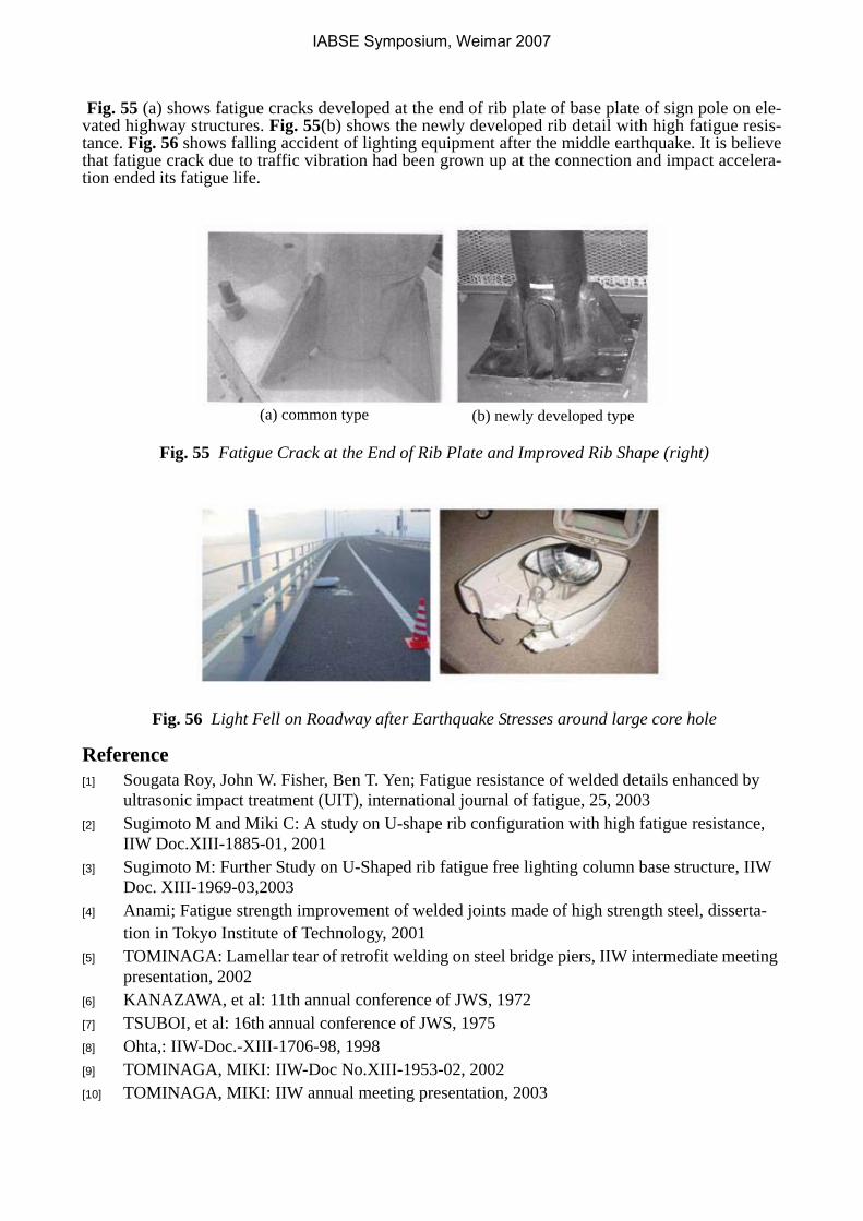
Fig. 55 (a) shows fatigue cracks developed at the end of rib plate of base plate of sign pole on ele-vated highway structures. Fig. 55(b) shows the newly developed rib detail with high fatigue resis-tance. Fig. 56 shows falling accident of lighting equipment after the middle earthquake. It is believethat fatigue crack due to traffic vibration had been grown up at the connection and impact accelera-tion ended its fatigue life.
Fig. 55 Fatigue Crack at the End of Rib Plate and Improved Rib Shape (right)
Fig. 56 Light Fell on Roadway after Earthquake Stresses around large core hole
Reference[1] Sougata Roy, John W. Fisher, Ben T. Yen; Fatigue resistance of welded details enhanced by
ultrasonic impact treatment (UIT), international journal of fatigue, 25, 2003[2] Sugimoto M and Miki C: A study on U-shape rib configuration with high fatigue resistance,
IIW Doc.XIII-1885-01, 2001[3] Sugimoto M: Further Study on U-Shaped rib fatigue free lighting column base structure, IIW
Doc. XIII-1969-03,2003[4] Anami; Fatigue strength improvement of welded joints made of high strength steel, disserta-
tion in Tokyo Institute of Technology, 2001[5] TOMINAGA: Lamellar tear of retrofit welding on steel bridge piers, IIW intermediate meeting
presentation, 2002[6] KANAZAWA, et al: 11th annual conference of JWS, 1972[7] TSUBOI, et al: 16th annual conference of JWS, 1975[8] Ohta,: IIW-Doc.-XIII-1706-98, 1998[9] TOMINAGA, MIKI: IIW-Doc No.XIII-1953-02, 2002[10] TOMINAGA, MIKI: IIW annual meeting presentation, 2003
(a) common type (b) newly developed type
IABSE Symposium, Weimar 2007