Embed Size (px)
Citation preview
Shack–Hartmann multiple spots with diffractive lensesF. Castignoles,1,4 T. Lepine,1,2,* P. Chavel,2,3 and G. Cohen4
1Laboratoire Hubert Curien (UMR 5516 CNRS), Université de Lyon, Université Jean-Monnet, F-42000, Saint-Etienne, France2Institut d’Optique Rhône-Alpes, 18 Rue Benoît Lauras F-42000, Saint-Etienne, France
3Laboratoire Charles Fabry de l’Institut d’Optique, Université Paris-Sud, CNRS, Palaiseau, France4 Cabinet d’Ophtalmologie, Lyon, F-69006, France
*Corresponding author: [email protected]
Received February 22, 2011; accepted February 23, 2011;posted March 21, 2011 (Doc. ID 142766); published April 13, 2011
In this Letter we aim to bring an understanding to the apparition of multiple spots when using a Shack–Hartmann(SH) wavefront sensor behind diffractive lenses. In contrast to previous work, this phenomenon is described interms of diffractive orders. It is illustrated with Zemax simulations, where three kinds of diffractive lenses (mono-focal, bifocal, and trifocal) are set behind a microlens array. The presence of multiple spots is related to the phasejump of the diffractive profile and also to the number of steps seen through the microlens pupil. The possibility ofassessing the optical quality of such lenses using SH measurements is discussed, in particular within the field ofophthalmology, where the need for precautions is underlined. © 2011 Optical Society of AmericaOCIS codes: 050.1965, 170.4470, 040.1240.
When measuring diffractive lenses behind a Shack–Hartmann (SH) wavefront sensor, it has been shown thatmultiple spots can appear [1–3]. Physically misunder-standing that effect can lead to wrong conclusions aboutthe optical quality of such lenses. This is particularly truein ophthalmology, for example, for patients with diffrac-tive intraocular implants after operations for cataractthat correct presbyopia at the same time [4].While Schwiegerling and DeHoog [1] have complemen-
ted previous medical publications [1–5] by physicallyinvestigating the effect, we shed new light by directly re-lating the spot pattern obtained on an SH behind a dif-fractive lens with diffractive orders rather than only withthe number of phase jumps in a given SH pupil, as was infact already explained by Charman et al. [3]. That has, inturn, a direct implication on the number of spots obser-vable and its changes with wavelength, which we analyzequantitatively for the first time. We further illustrate theeffect by using Zemax simulations with several kinds ofdiffractive lenses [6].Figure 1 shows the three diffractive lenses studied:
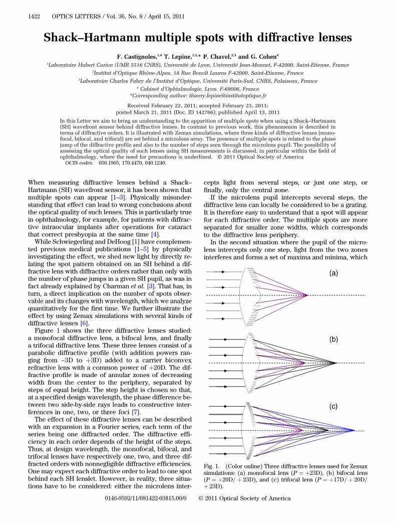
a monofocal diffractive lens, a bifocal lens, and finallya trifocal diffractive lens. These three lenses consist of aparabolic diffractive profile (with addition powers ran-ging from −3D to þ3D) added to a carrier biconvexrefractive lens with a common power of þ20D. The dif-fractive profile is made of annular zones of decreasingwidth from the center to the periphery, separated bysteps of equal height. The step height is chosen so that,at a specified design wavelength, the phase difference be-tween two side-by-side rays leads to constructive inter-ferences in one, two, or three foci [7].The effect of these diffractive lenses can be described
with an expansion in a Fourier series, each term of theseries being one diffracted order. The diffractive effi-ciency in each order depends of the height of the steps.Thus, at design wavelength, the monofocal, bifocal, andtrifocal lenses have respectively one, two, and three dif-fracted orders with nonnegligible diffractive efficiencies.One may expect each diffractive order to lead to one spotbehind each SH lenslet. However, in reality, three situa-tions have to be considered: either the microlens inter-
cepts light from several steps, or just one step, orfinally, only the central zone.
If the microlens pupil intercepts several steps, thediffractive lens can locally be considered to be a grating.It is therefore easy to understand that a spot will appearfor each diffractive order. The multiple spots are moreseparated for smaller zone widths, which correspondsto the diffractive lens periphery.
In the second situation where the pupil of the micro-lens intercepts only one step, light from the two zonesinterferes and forms a set of maxima and minima, which
Fig. 1. (Color online) Three diffractive lenses used for Zemaxsimulations: (a) monofocal lens (P ¼ þ23D), (b) bifocal lens(P ¼ þ20D=þ 23D), and (c) trifocal lens (P ¼ þ17D=þ 20D=þ 23D).
1422 OPTICS LETTERS / Vol. 36, No. 8 / April 15, 2011
0146-9592/11/081422-03$15.00/0 © 2011 Optical Society of America
can formally be analyzed as resulting from the diffractiveorders, although they overlap and are not well separated.Finally, in the case where the pupil intercepts only one
zone—typically the central zone, no interferences be-tween the rays of different steps can be produced, so thatonly a single spot will result, whatever type of diffractivelens is used. In fact, in this case the coherent sum of thedifferent diffractive orders can be shown to equate asingle wave corresponding to the curvature of the centralzone.We will now present numerical illustrations of these
different situations with Zemax simulations. Our modelis illustrated in Fig. 2.It is composed of one diffractive lens and of the micro-
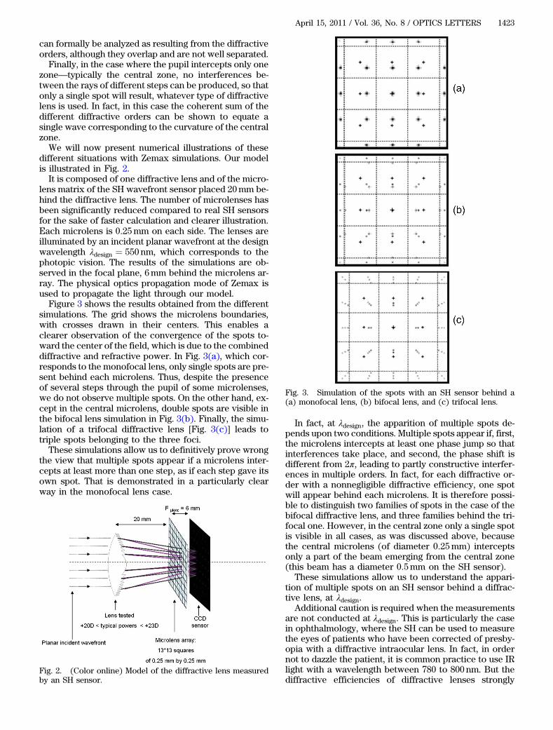
lens matrix of the SH wavefront sensor placed 20mm be-hind the diffractive lens. The number of microlenses hasbeen significantly reduced compared to real SH sensorsfor the sake of faster calculation and clearer illustration.Each microlens is 0:25mm on each side. The lenses areilluminated by an incident planar wavefront at the designwavelength λdesign ¼ 550 nm, which corresponds to thephotopic vision. The results of the simulations are ob-served in the focal plane, 6mm behind the microlens ar-ray. The physical optics propagation mode of Zemax isused to propagate the light through our model.Figure 3 shows the results obtained from the different
simulations. The grid shows the microlens boundaries,with crosses drawn in their centers. This enables aclearer observation of the convergence of the spots to-ward the center of the field, which is due to the combineddiffractive and refractive power. In Fig. 3(a), which cor-responds to the monofocal lens, only single spots are pre-sent behind each microlens. Thus, despite the presenceof several steps through the pupil of some microlenses,we do not observe multiple spots. On the other hand, ex-cept in the central microlens, double spots are visible inthe bifocal lens simulation in Fig. 3(b). Finally, the simu-lation of a trifocal diffractive lens [Fig. 3(c)] leads totriple spots belonging to the three foci.These simulations allow us to definitively prove wrong
the view that multiple spots appear if a microlens inter-cepts at least more than one step, as if each step gave itsown spot. That is demonstrated in a particularly clearway in the monofocal lens case.
In fact, at λdesign, the apparition of multiple spots de-pends upon two conditions. Multiple spots appear if, first,the microlens intercepts at least one phase jump so thatinterferences take place, and second, the phase shift isdifferent from 2π, leading to partly constructive interfer-ences in multiple orders. In fact, for each diffractive or-der with a nonnegligible diffractive efficiency, one spotwill appear behind each microlens. It is therefore possi-ble to distinguish two families of spots in the case of thebifocal diffractive lens, and three families behind the tri-focal one. However, in the central zone only a single spotis visible in all cases, as was discussed above, becausethe central microlens (of diameter 0:25mm) interceptsonly a part of the beam emerging from the central zone(this beam has a diameter 0:5mm on the SH sensor).
These simulations allow us to understand the appari-tion of multiple spots on an SH sensor behind a diffrac-tive lens, at λdesign.
Additional caution is required when the measurementsare not conducted at λdesign. This is particularly the casein ophthalmology, where the SH can be used to measurethe eyes of patients who have been corrected of presby-opia with a diffractive intraocular lens. In fact, in ordernot to dazzle the patient, it is common practice to use IRlight with a wavelength between 780 to 800 nm. But thediffractive efficiencies of diffractive lenses strongly
Fig. 2. (Color online) Model of the diffractive lens measuredby an SH sensor.
Fig. 3. Simulation of the spots with an SH sensor behind a(a) monofocal lens, (b) bifocal lens, and (c) trifocal lens.
April 15, 2011 / Vol. 36, No. 8 / OPTICS LETTERS 1423
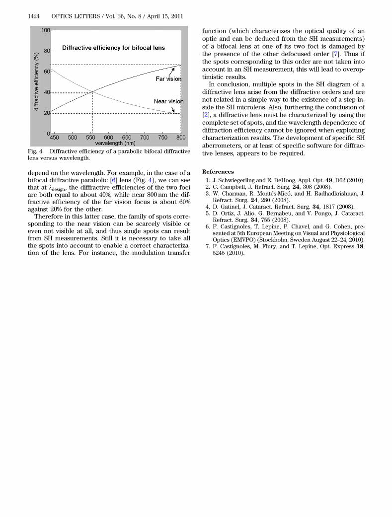
depend on the wavelength. For example, in the case of abifocal diffractive parabolic [6] lens (Fig. 4), we can seethat at λdesign, the diffractive efficiencies of the two fociare both equal to about 40%, while near 800 nm the dif-fractive efficiency of the far vision focus is about 60%against 20% for the other.Therefore in this latter case, the family of spots corre-
sponding to the near vision can be scarcely visible oreven not visible at all, and thus single spots can resultfrom SH measurements. Still it is necessary to take allthe spots into account to enable a correct characteriza-tion of the lens. For instance, the modulation transfer
function (which characterizes the optical quality of anoptic and can be deduced from the SH measurements)of a bifocal lens at one of its two foci is damaged bythe presence of the other defocused order [7]. Thus ifthe spots corresponding to this order are not taken intoaccount in an SH measurement, this will lead to overop-timistic results.
In conclusion, multiple spots in the SH diagram of adiffractive lens arise from the diffractive orders and arenot related in a simple way to the existence of a step in-side the SH microlens. Also, furthering the conclusion of[2], a diffractive lens must be characterized by using thecomplete set of spots, and the wavelength dependence ofdiffraction efficiency cannot be ignored when exploitingcharacterization results. The development of specific SHaberrometers, or at least of specific software for diffrac-tive lenses, appears to be required.
References
1. J. Schwiegerling and E. DeHoog, Appl. Opt. 49, D62 (2010).2. C. Campbell, J. Refract. Surg. 24, 308 (2008).3. W. Charman, R. Montés-Micó, and H. Radhadkrishnan, J.
Refract. Surg. 24, 280 (2008).4. D. Gatinel, J. Cataract. Refract. Surg. 34, 1817 (2008).5. D. Ortiz, J. Alio, G. Bernabeu, and V. Pongo, J. Cataract.
Refract. Surg. 34, 755 (2008).6. F. Castignoles, T. Lepine, P. Chavel, and G. Cohen, pre-
sented at 5th European Meeting on Visual and PhysiologicalOptics (EMVPO) (Stockholm, Sweden August 22–24, 2010).
7. F. Castignoles, M. Flury, and T. Lepine, Opt. Express 18,5245 (2010).
Fig. 4. Diffractive efficiency of a parabolic bifocal diffractivelens versus wavelength.
1424 OPTICS LETTERS / Vol. 36, No. 8 / April 15, 2011