Embed Size (px)
Citation preview

LJkn UNIVERSITÉ DU LITTORAL
~ ~ CÔTE D'OPALE
Rayonnement du corps noir
Loi de Stefan~Boltzmann Thermistances
Introduction:
Ce projet vous permet d'étudier le rayonnement des corps chauffés (rayonnement thermique) Le matériel dont vous disposez vous permet de faire varier la température de la source lumineuse (source=tilament d'une lampe à incandescence) et d'étudier comment évolue la puissance reçue sur le détecteur de lumière (thermopile) en fonction de la température. Ces expériences doivent vous permettre de retrouver la loi fondamentale de StefanBoltzmann, Celle~ci permet en effet de relier la puissance émise par unité de surface de la source (en W.m·2
) à sa temperature T .
1- Rayonnement thermique
1) Le co'rps noir (eN) AI' équilibre tnermique (température TCN), le corps noir absorbe l'intégralité du
rayonnement qu'il reçoit. Par ailleurs, il le rUmet en totaJité (émissivité f;=1). Le corps noir eSl ainsi appelé « absorbeur intégral et émetteur intégral »), La plupart des corps ne sont pas véritablement des corps noirs, ce qui signifie qu'ils ne réémettent pas en totalité ce qu'ils ont reçu (émissivité O<e<l). Cependant, la ' loi de variation 'du rayonnement produit avec la lempérature demeure la même dans les deux cas , Ces corpS,sont appelés « Corps Gris »),
,
2) Formule de Planck Cette formule exprime [a brillance MT(À) du corps noir à la température T, c'est à dire la puissance émise par unité de surface du corps et par intervalle spectral autour de la longueur d'onde À" L'expression de Mr(À.) est la suivante :
k=1,38.10."23 lK- j (ete de Boltzmann) c=3, 108 m.s· l (vitesse de la [umi ère d ans le v ide) M (~)' ' W ,2 ,1 T 1\. S exprime en ,m ,nm

E c
Q) o c ro-
1 Ë7 ...... :
-1 ooa09~:' . Hio-oou .··'·
10-0.00
100.0
.1 DO i
1.0:
,+-, _0,1
' C 001 cc.
j'E-J
I,E·4 ", . ~ ..
)'E·~ -F'''---.--,JC-.,.-...... '-'r-' ' '"-+' ' -,' ~~"----'-'-'--"-'-r:'-.I.;....;--b-+4-ri---1+-..:....:...~~,,:..,-.~., .... , TO:+i, -Mi,''-j---'-'''''''':;'''':'_:'r'"IT ,
\I~'-l: (E ;,~' ' 1 :?-S l 'E -,4
L6~g.lie.ür 'd!o,ndê': (m)
Pour une température de Corps noir donnée, il eXiste une longueur d'onde À-m pour laquelle la brillance MT est maximale. Cette longueur d'onde permet de défmir la « couleur ») du corps.
3) Loî de Stefan-Boltzmann La puissance totale émise LCN (pour toutes les longueurs d'onde) par le corps noir par
unité de surface de ce corps, est proportionnelle à sa température absolue T (en Kelvins) à la puissance 4. Pour le corps noir on trouve LCN(T)=crT4 (avec cr=5,67, 10.8 W.m·2 .K4
) _
Cette expression est obtenue en intégrant la formule de Planck à une température T pour toutes les longueurs d'onde. ce qui peut s' écrire:
+00
LCN (T)::: J MT O\-).dÀ o
Pour un corps gris (CG). on aura simplement Lcc(T)==ê .LCN(T)=e.crT4 (E~missjvité) Lce et LCN s'expriment donc en W ,m·2
.
II- Expériences
Vous avez la possibilité de faÎre diverses expériences. La source lumineuse dont vous disposez ici correspond simplement à une ampoule à incandescence. Le ( corps noir» est dOl1c constitue du fdament de l'ampoule. Ce filament se comporte comme une thermistance, c'est à dire que sa résistance électrique (en Ohms) varie avec sa température. En augmentant l'intensité 1 du courant traversant le fIlament, on augmente sa température et donc aussi la brillance de j' ampoule . La brillance peut être mesurée par un détecteur thermique (thermopile) . Avec ce matériel, vous devez donc pouvoir tracer la brillance mesurée en fonction de la température du filament (mesurée indirectement par sa résistance).
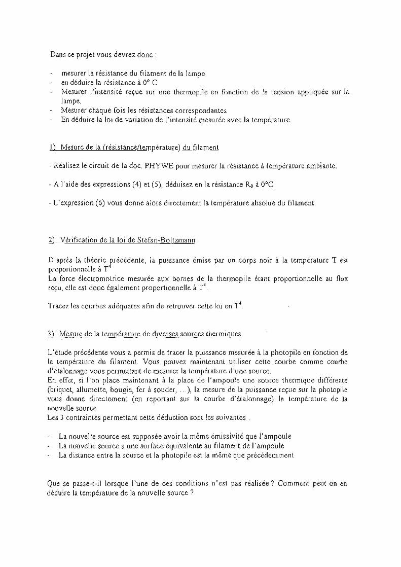
Dans ce projet vous devrez donc:
mesurer la résistance du ftlament de la lampe en déduire la résistance à 0° C Mesurer l'intensité reçue sur une thermopile en fonction de la tension appliquée sur la lampe. Mesurer chaque fois les résistances correspondantes En déduire la loi de variation de l'intensité mesurée avec la température.
1) Mesure de la (résistance/température) du fIlament
- Réalisez le circuit de la doc. PHYWE pour mesurer la résistance à température ambiante.
- A l'aide des expressions (4) et (5), déduisez en la résistance RD à O°c.
- L'expression (6) vous donne alors directement la température absolue du filament.
2) Vérification de la loi de Stefan-Boltzmann
D'après la théorie précédente, la puissance émise par un corps noir à la température Test proportionnelle à T La force électromotrice mesurée aux bornes de [a thermopile étant proportionnelle au flux reçu, e[le est donc également proportionneUe à T4
.
Tracez les courbes adéquates afin de retrouver cette loi en T4.
3) Mesure de la température de diverses sources thermiques
L'étude précédente vous a permis de tracer la puissance mesurée à la photopile en [onction de la température du filament. Vous pouvez maintenant utiliser cette courbe comme courbe d'étalonnage vous permettant de mesurer la températllfe d'une source. En effet, si l'on place maintenant à la place de 1) ampoule une source thermique différente (briquet, aJJumette, bougie, fer à souder, ... ), la mesure de la puissance reçue sur la photopile vous donne directement (en reportant sur la courbe d'étalonnage) la température de la nouvelle source. Les 3 contraintes permettant cette déduction sont les suivantes.
La nouvelle source est supposée avoir la même émissivité que l'ampoule La nouvelle source a une surface équivalente au filament de l'ampoule La distance entre la source et la photopile est la même que précédemment
Que se passe-t-il lorsque l'une de ces conditions n'est pas réalisée? Comment peut on en déduire la température de la nouvelle source?
~L-_ .... _ .......... ..... .... S ....... t .... e .. f.a". -_ .. B ...... O ........ I .. t ... z ... _m.a." ...... " ....... ' .. S ........ I ... a ..... W ............ O ..... f ....... r .... a ...... d .. . _ia. t .... i .. O ..... _" ......................... .. ...... ....... .. ....... _._ ... J
LEP 3.5.01
Related topics Problems
Black body radiation , thennoelectric e.m.f., temperature dependence of resistances.
1. To measure the resistance of the filament of the incandescent lamp at room temperature and to ascertain the filament's resistance Ra at zero degrees centrigrade.
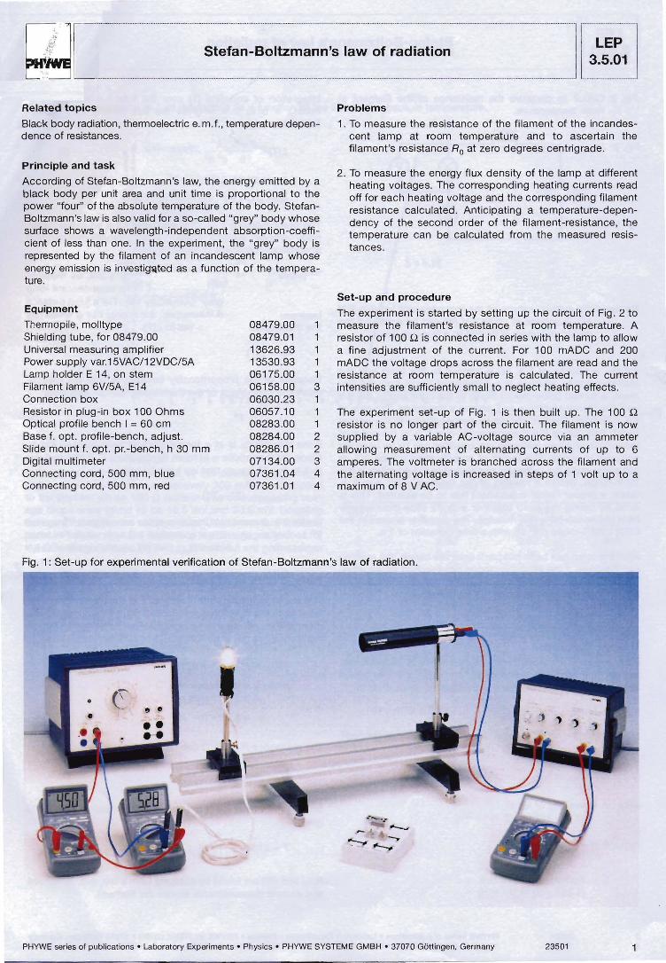
Principle and task
According of Stefan-Boltzmann's law, the energy emitted by a black body per unit area and unit time is proportional to the power "four" of the absolute temperature of the body. StefanBoltzmann's law is also valid for a so-called "grey" body whose surface shows a wavelength-independent absorption-coefficient of less than one. In the experiment, the "grey" body is represented by the filament of an incandescent lamp whose energy emission is investig""'lted as a function of the temperature.
2. To measure the energy flux density of the lamp at different heating voltages. The corresponding heating currents read off for each heating voltage and the corresponding filament resistance calculated . Anticipating a temperature-dependency of the second order of the filament-resistance, the temperature can be calculated from the measured resistances.
Equipment
Thennopile , molltype Shielding tube, for 08479.00 Universal measuring amplifier Power supply var.15VAC/12VDC/5A Lamp holder E 14, on stem Filament lamp 6V/5A, E14 Connection box Resistor in plug-in box 100 Ohms Optical profile bench 1 = 60 cm Base f. opt. profile-bench , adjust. Slide mount f. opt . pr.-bench, h 30 mm Digital multimeter Connecting cord, 500 mm, blue Connecting cord, 500 mm, red
08479.00 08479.01 13626.93 13530.93 06175 .00 06158 .00 06030.23 06057 .10 08283.00 08284.00 08286.01 07134.00 07361.04 07361 .01
Set-up and procedure
The experiment is started by setting up the circuit of Fig. 2 to 1 measure the filament's resistance at room temperature. A 1 resistor of 100 [2 is connected in series with the lamp to allow 1 a fine adjustment of the current. For 100 mADC and 200 1 mADC the voltage drops across the filament are read and the 1 resistance at room temperature is calculated. The current 3 intensities are sufficiently small to neglect heating effects. 1 1 The experiment set-up of Fig . 1 is then built up. The 100 n 1 resistor is no longer part of the circuit. The filament is now 2 supplied by a variable AC-voltage source via an ammeter 2 allowing measurement of alternating currents of up to 6 3 amperes. The voltmeter is branched across the filament and 4 the alternating voltage is increased in steps of 1 volt up to a 4 maximum of 8 V AC .
Fig. 1: Set-up for experimental verification of Stefan-Boltzmann's law of radiation.
, !II e
PHYWE series of publicat ions ' Laboratory Experiments • Physics • PHYWE SYSTEME GMBH· 37070 G6ttingen. Germany 23501

1 3~:~1 I ~I ______________ S __ te_f_a_n_-B __ o_lt_z_m_a_n_n_'_S_13W __ O_f_r_3_d_i_a_ti_o_n ______________ ~I~ Fig. 2: Circuit 10 measure the resistance of the filament at
room lemperature.
lOon
O ... 10V-
Remark: the supply voilage of Ihe incandescent lamp is 6 V AC . A voilage of up ta 8 V AC can be applied if the period of suppl Y is limned 10 a 1ew minules.
Initially, a voltage of 1 V AC is applied to Ihe lamp and the Mali-thermopile, which is at a distance of 30 cm trom Ihe litament, is lurned (slide-moun! fixed) to the right and 10 Ihe lefl untilthe Ihermoelectric e. m . f. shows a maximum. The axis of the cylindrical filament should be perpendicular to the optical bench axis. Since the thermoeleclric e .m.1. is in the order of magnitude of a lew millivolts, an amplifier has \0 be used for accurate readings. The faclor 01 amplification will be 102 or 103 when using the voUme1 er connecled la the amplifier in Ihe 10 V range. Belore a reading of the thermoeleclric e. m . f. is taken. a proper "zero"-adjustmenl has ta be assured. This is done by taking the lamp logether with its slide-mount away frcm the bench for a few mÎnutes. The amplifier is used in the LOW DRIFT-mode (10 4 0) with a time constant of 1 s.
After the tamp has been put back onto Ihe bench, the reading can be taken if the Moll-thermopile has reached its equilibrium. This takes about one minute. Care must be taken that no background radiation dislllrbs the measuremen1.
Theory and evalutron
tf the energy flux densily L of a black body, e.g. energy emitled per unit area and unit time al temperature T and wavelength À wilhin the inlerval d>.., is designated by dL(7", >-"Yd>..,
Planck's formula states:
dL(A, 7) _ 2c2 hA-5 dA. - efZ;-1
wilh: c "" velocny of light (3.00 . 109 fm/sn
h '" Planck's constant (6 .62 . 10-34 [J . 5J)
k Bolt~mann's cot'lStant (1.381 . 1 O~J [J . K"ln
(1)
Integration of equation (1) over the total wavelength-range from À = 0 10 >-.. = ..., glves the flux dansity L(T) (SlelanBollzmann's law).
217 5 k· ~ L(7) "" 15 . c2 h3 . T (2)
re5pectively L(Tl = cr . T'
wilh cs == 5 .67·10-8 [W · m-z , ~J
The proportionality L - r is also vslid for a so-called "grey" body whose sur1ace shows a wavelength-indepandenl absorption-coefficient of less Ihan one.
To prove the validity of Slelan-Boltzmann's law. we me3sure lhe radiation emltted by the Jilament of an incandescent lamp which represents a "grey" body (airly weil. For a fixed distance betwaen filament and Ihermopile, Ihe energy flux 4> which hils the thermopile is proportionalto L(T).
<l> - L(7)
8ecause of the propOrlionality between <Il and the thermoelectric e.m .f ., Ultlelm of the thermopile. we can also write:
if the thermopile is at a temperature of zero degrees Kelvin. Since Ihe thermopile is at room temperalure T Rit also radiales due to the r law 50 that we have ta write:
Ulne,m - (T' - T~)
Under the present c(rcumstances. we can neglect ~ agaiost r so Ihat we shol.1ld get a straight line with slope " 4" when representing the function U(nelrn = f(T) double logarithmically.
Ig U(n.lm ~ 4 Ig T + conSl . (3)
The absolute temperature T == 1 + 273 of the filament is calculated trom the measured resÎstances R(I) of the lungslen filament (1 "" temperature in centigrade). For the tungsten filament resistance, we have the follawing temperalure dependence:
R(r) == Ro (1 + ct! + f3r2-)
with Ac = reslstance at O·C ct ::: 4.82 ' 10-3 K"1
(3 '" 6.76 . 10-7 1("'1
(4)
The reslstance Ro at O°C can be !ound by using the relation:
(5)
Solviog A(t) with respect 10 t and using the (elatÎon T = t + 273 gives:
(6)
R(t~ and R(I) are found by applying Ohm's law, e. g. by voltage and currenl measurements across the filament.
2 23501 PHYWE saties 01 pui:)l icatioos • Laoo,alOty Experime~ls • Physics • PHYWE SYSTEME GMBH' 37070 Gôtti"gGn. Gellm,,)!
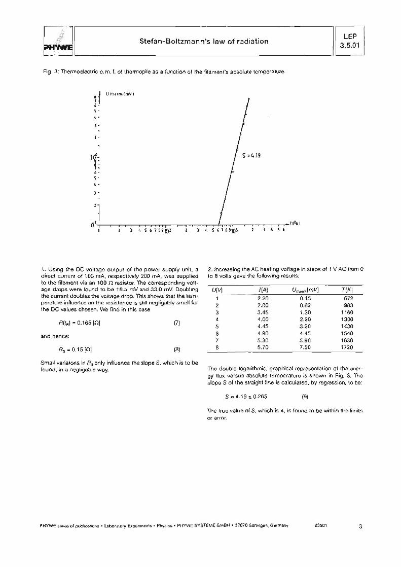
~I~ ______________ S_t_e_fa_n_-_B_o_lt_2_m_a_n_n_'_S_I_a_W __ Of __ ra_d_i_a_ti_o_n ____________ ~1 1 3~:'~1 1 Fig 3: Thermoelectric e.m. r. of thermopile as a funcliol"\ of Ihe filament's absolute temperalure.
U Ihum,t mV 1
cr\+-r--r--r-r--r--r-,....,.."TT-r--.--....-.,.-.---r--r-f-r.,...,.r----.-~ ........ ---,__,---r-l (OK 1 1 l ~ S 6 7 69101
1. Using the OC voltage output of the power supply unit, a direct current of 100 mA, respectively 200 mA, was supplied 10 the filament via an 1000 resistor. The eorresponding voilage drops were found 10 ba 16.5 mV and 33.0 mV. Doubling the current doubles the voltage drop. This shows Ihat the lemperature influence on the resistanee is still negligably small for the DC values chosen. We find in this case
A(trJ = 0.165 [0) (7)
and hence:
Ro = 0.15 [0) (B)
Small varialons in Ro only influence the slope 5, which is to be found, ln a negligable way.
) ~ S 6
2. Increasing Ihe AC heating voilage in steps of 1 V AC lrom 0 la 8 volis gave the following results;
UIV) I[A) Utnerm[mV) T[K)
2.20 0.15 672 2 2.80 0.62 9B3 3 3.45 1.30 1160 4 4.00 2.20 1300 5 4.45 3.20 1430
6 4.90 4.45 1540 7 5.30 5.90 16.30
8 5.70 7.50 1720
The double logarithmic, graphieal representalion of the anergy flux versus absolute tempe rature is shown in Fig. 3. The slope S of the slraight line is calculatoo, by regression, \0 be:
s = 4.19 %. 0.265 (9)
The true value of S, which is 4, is found la be within the !imits or error.
PHYWE series 01 pub Il calions • Labo'alory upe"menls • Physics • PHVWE SYSTEME GMBH· 37070 Glltti"9Bn. Ge1many 23501 3