Embed Size (px)
Citation preview
Unité portable pour récupération / recyclage de réfrigérant
Manuel d’utilisation
EASYREC120R100 MANUALE D’USO ITALIANO
WIGAM 2
La WIGAM S.p.a. se réserve le droit de modifier les données et les caractéristiques contenues dans ce manuel sans préavis, selon sa politique de constante amélioration de ses produits
Réalisation: WIGAM S.p.A Imprimé en Italie 1ère édition: Janvier 2010
EASYREC120R100 MANUALE D’USO ITALIANO
WIGAM 3
SOMMAIRE Schéma hydraulique ............................................................................................................... 4 Schéma électrique .................................................................................................................. 5 Normes de sécurité et lignes guides pour l’utilisation ....................................................... 6 1. Introduction à l'unité de récupération EASYREC120R100 ........................................... 8 2. Description des composants et équipement standard ................................................ 8
2.1. Compresseur de récupération ......................................................................................................................8 2.2. Filtre ...............................................................................................................................................................8 2.3. Voyant humidité .............................................................................................................................................8 2.4. Manomètres ...................................................................................................................................................8 2.5. Système de distillation ..................................................................................................................................8
3. Tableau de commande .................................................................................................... 9 4. Récupération et recyclage du réfrigérant du système A/C ........................................ 10
4.1. Avvertissements ............................................................................... Errore. Il segnalibro non è definito. 4.2. Récupération/Recyclage du réfrigérant .................................................................................................... 10 4.3. Récupération du réfrigérant ....................................................................................................................... 12
5. Procédure “Self-purge” ................................................................................................. 14 5.1. Avertissements ........................................................................................................................................... 14 5.2. Fonction “purge” ........................................................................................................................................ 14
6. Transfert du réfrigérant avec la méthode Push-Pull ................................................... 15 6.1. Avertissements ........................................................................................................................................... 15 6.2. Transfert du réfrigérant .............................................................................................................................. 16
7. Procédure de refroidissement de la bonbonne de récupération ............................... 17 7.1. Préparation pour la procédure de refroidissement .................................................................................. 17 7.2. Procédure de refroidissement durant la récupération ............................................................................. 18
8. Entretien courant ........................................................................................................... 19 8.1. Matériel nécessaire .................................................................................................................................... 19 8.2. Interventions périodiques d'entretien courant .......................................................................................... 19
9. "Remise à zéro" du pressostat de max ....................................................................... 19 10. Caractéristiques techniques ..................................................................................... 19 11. Résolution des problèmes ........................................................................................ 20
EASYREC120R100 MANUALE D’USO ITALIANO
WIGAM 4
Schéma hydraulique
M1 Manomètre aspiration V1 Vanne1 pour système distillateur M2 Manomètre refoulement V2 Vanne 2 pour système distillateur SP1 Pressostat de sécurité V3 Vanne vidange huile SP2 Pressostat/vacuostat 1 Compresseur INPUT valve Vanne sur la ligne basse pression 2 Condensateur OUTPUT valve Vanne sur la ligne haute pression 3 Ventilateur Recover/Purge Vanne Récupération / Purge 4 Distillateur CV1 Vanne anti-retour ligne de
refoulement
EASYREC120R100 MANUALE D’USO ITALIANO
WIGAM 5
Schéma électrique
XS Prise de courant C2 Condensateur de marche SA Interrupteur principal TC Transformateur électronique FR Dispositif de protection pour surcharge SP1 Pressostat de sécurité M1 Moteur du compresseur SP2 Pressostat /vacuostat M2 Ventilateur axial SB1 Touche de mise en marche K1 Relais SK Interrupteur By-Pass K2 Relais HL1 Indicateur de protection haute pression K5 Relais HL2 Indicateur de protection basse pression SR Interrupteur centrifuge ST Thermo-protections du moteur C1 Condensateur de démarrage
EASYREC120R100 MANUALE D’USO ITALIANO
WIGAM 6
ATTENTION
Normes de sécurité et lignes guides pour l’utilisation
a) Lire attentivement ce manuel avant d’utiliser l’unité de récupération. b) L’unité de récupération est destinée exclusivement aux opérateurs professionnels qui doivent connaître
les principes de la réfrigération, les systèmes frigorifiques, les gaz réfrigérants et les dommages qui peuvent être provoqués par des appareils sous pression.
c) Utiliser des protections appropriées telles que lunettes et gants; le contact avec le réfrigérant peut provoquer la cécité et d’autres dommages physiques à l’opérateur.
d) Ne pas exposer l’unité au soleil ou à la pluie e) Faire fonctionner l’unité seulement dans des locaux avec une ventilation appropriée et une bonne
circulation d’air. f) Utiliser UNIQUEMENT des bonbonnes de réfrigérant rechargeables autorisées. Celles-ci doivent avoir
une pression d’exercice de minimum 27.6 bar. g) Ne jamais remplir une bonbonne de récupération avec du réfrigérant liquide à plus de 75% de sa
capacité maximale. Un remplissage excessif peut provoquer une explosion. h) Ne pas dépasser la pression d’exercice de la bonbonne de récupération. i) Ne pas mélanger des réfrigérants différents dans une même bonbonne. j) Avant de récupérer le réfrigérant, la bonbonne doit atteindre un degré de vide de -0.9 MPa, pour pouvoir
enlever les gaz non condensables et l’éventuelle humidité. k) Lorsque l’unité n’est pas utilisée, toutes les vannes doivent être fermées et les raccords d’entré et de
sortie couverts avec leurs capuchons de protection ; l’air et l’humidité peuvent amoindrir les performances de récupération et réduire la durée du compresseur.
l) Si l’on utilise une rallonge électrique, la section des câbles doit être d’au moins 2.0mm2 et le câble ne doit pas dépasser les 30 mètres car cela pourrait provoque une baisse de tension et endommager le compresseur..
m) Toujours utiliser un filtre déshydrateur et le remplacer fréquemment. Chaque type de réfrigérant doit avoir son propre filtre. Afin d’assurer un bon fonctionnement à l’unité, il est conseillé d’utiliser le filtre proposé par Wigam. Remplacer le filtre chaque fois que le voyant indique la présence d’humidité.
n) Prêter une grande attention lorsque l’on récupère à parti d’un système « brûlé ». Utiliser deux filtres pour acide de haute capacité. Au terme de la récupération, laver l’unité de récupération avec une petite quantité de réfrigérant propre et avec de l’huile réfrigérante pour nettoyer les éventuelles substances étrangères restées à l’intérieur.
o) L’unité a un dispositif d’arrêt automatique de haute pression. Si la pression à l’intérieur du système monte au-delà de 38.5 bar, l’unité s’éteindra automatiquement et le témoin rouge d’alarme s’allumera. Le compresseur doit être redémarré, la cause du problème doit être trouvée et ensuite la pression interne doit être réduite au-dessous de 25 bar. Appuyer sur le bouton START pour faire repartir le compresseur. Lorsque l’unité se trouve en condition de haute pression, faire redémarrer l’unité après avoir éliminé les problèmes. - Solutions aux causes possibles d’un arrêt dû à la haute pression:
1. Ouvrir la vanne OUTPUT de l’unité, si fermée. 2. Ouvrir la vanne d’entrée de la bonbonne de récupération si fermée. 3. Vérifier si le flexible de raccordement entre l’unité et la bonbonne de récupération est obstrué. Si
c’est le cas, fermer la vanne OUTPUT de l’unité et la vanne d’entrée de la bonbonne, puis, changer le flexible.
4. La température et la pression de la bonbonne sont trop hautes (voir la procédure de refroidissement de la bonbonne)
p) Durant l’utilisation de l’unité, s’assurer que le système de conditionnement est éteint. q) L’unité ha un dispositif d’arrêt automatique de basse pression (pressostat/vacuostat). Si la pression
interne est inférieure à -0.2 ÷ -0.4bar, l’unité s’éteint automatiquement et le témoin vert s’allume. Pour faire redémarrer le compresseur, augmenter la pression d’entrée au-dessus de +0.4 bar ou tourner l’interrupteur BY-PASS sur la position manuelle et ensuite appuyer sur le bouton START.
EASYREC120R100 MANUALE D’USO ITALIANO
WIGAM 7
r) Interrupteur BY-PASS : - lorsque l’interrupteur BY-PASS est sur la position AUTO, le pressostat/vacuostat intervient. - lorsque l’interrupteur BY-PASS est sur la position MANUELLE, le pressostat/vacuostat n’intervient pas. Mettre l’interrupteur sur la position MANUELLE lorsque la pression du système est inférieure à +0.4 bar ou si le système nécessite un haut vide.
s) Si la pression de la bonbonne dépasse 21 bar, utiliser la procédure de refroidissement pour réduire la pression.
t) Pour optimiser la vitesse de récupération, utiliser un flexible le plus court possible. u) Durant la récupération de grandes quantités de réfrigérant liquide, utiliser la méthode Push/Pull. v) Après la récupération, s’assurer qu’il n’y ait plus de réfrigérant dans l’unité. Lire la procédure de “Self-
Purge” attentivement. Si du réfrigérant liquide reste dans l’unité, il peut se répandre et endommager les composants.
w) En prévision d’une longue période d’inactivité ou si l’unité doit être rangée, évacuer tout résidu de réfrigérante et nettoyer l’unité avec de l’azote sec.
x) Nous conseillons d’utiliser des flexibles avec vanne pour réduire les pertes de réfrigérant.
EASYREC120R100 MANUALE D’USO ITALIANO
WIGAM 8
1. Introduction à l'unité de récupération EASYREC120R100 En considération de ses dimensions réduites et de son extrême facilité de transport, l'unité est particulièrement adaptée pour intervenir sur les installations de conditionnement civil, les installations de conditionnement des véhicules, les distributeurs automatiques, les réfrigérateurs ménagers et commerciaux et les déshumidificateurs. L'unité est équipée d'un compresseur à sec sans lubrifiant
2. Description des composants et équipement standard
2.1. COMPRESSEUR DE RECUPERATION
L'unité EASYREC120R100 est équipée d'un compresseur à sec adapté à tout type de réfrigérant CFC, HCFC et HFC.
2.2. FILTRE Le filtre déshydrateur est équipé de raccords mâles 1/4"SAE. Il est doté d’un flexible pour en faciliter le raccordement. L’unité dispose également d’un voyant d’humidité pour contrôler la qualité du filtre.
2.3. VOYANT HUMIDITE Le voyant d’humidité doit être relié entre le filtre et le récupérateur pour contrôler la qualité du filtre. Remplacer le filtre chaque fois que le voyant indique la présence d’humidité.
2.4. MANOMETRES
L’unité EASYREC120R100 est équipée de deux manomètres à bain d’huile Ø60mm: un manomètre sur la ligne d'aspiration et un sur la ligne de refoulement. Ils permettent le contrôle des pressions pendant les opérations de récupération et transfert du réfrigérant avec la méthode "Push-Pull".
2.5. SYSTEME DE DISTILLATION
L’unité EASYREC120R100 est dotée d’un système de distillation (que l’on peut exclure): celui-ci est équipé d’un dispositif automatique de réglage du flux et permet donc la séparation complète de l’huile provenant du système et du réfrigérant.
ATTENTION L’unité ne doit PAS travailler en vide pendant plus de 10 minutes (-0.02Mpa) lorsque l’interrupteur BY-PASS est sur la position manuelle.
EASYREC120R100 MANUALE D’USO ITALIANO
WIGAM 9
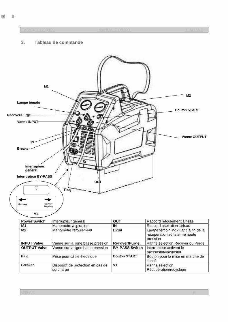
3. Tableau de commande
Power Switch Interrupteur général OUT Raccord refoulement 1/4sae M1 Manomètre aspiration IN Raccord aspiration 1/4sae M2 Manomètre refoulement Light Lampe témoin indiquant la fin de la
récupération et l’alarme haute pression
INPUT Valve Vanne sur la ligne basse pression Recover/Purge Vanne sélection Recover ou Purge OUTPUT Valve Vanne sur la ligne haute pression BY-PASS Switch Interrupteur activant le
pressostat/vacuostat Plug Prise pour câble électrique Bouton START Bouton pour la mise en marche de
l’unité Breaker Dispositif de protection en cas de
surcharge V1 Vanne sélection
Récupération/recyclage
M2
Bouton START
Vanne OUTPUT Valve
OUT
Breaker
Vanne INPUT
M1
Lampe témoin
Recover/Purge
Interrupteur général
Interrupteur BY-PASS
Plug
IN
RecoveryRecoveryRecycling
V1
EASYREC120R100 MANUALE D’USO ITALIANO
WIGAM 10
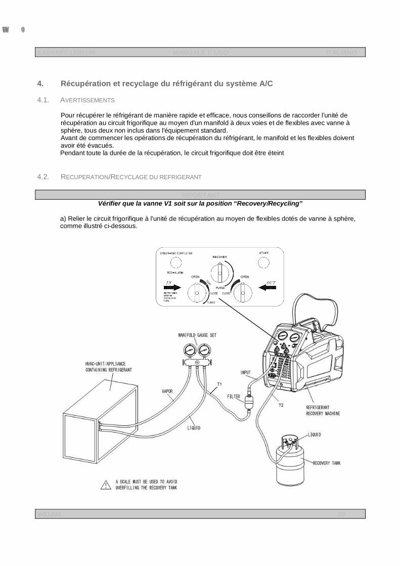
4. Récupération et recyclage du réfrigérant du système A/C
4.1. AVERTISSEMENTS
Pour récupérer le réfrigérant de manière rapide et efficace, nous conseillons de raccorder l'unité de récupération au circuit frigorifique au moyen d'un manifold à deux voies et de flexibles avec vanne à sphère, tous deux non inclus dans l'équipement standard. Avant de commencer les opérations de récupération du réfrigérant, le manifold et les flexibles doivent avoir été évacués. Pendant toute la durée de la récupération, le circuit frigorifique doit être éteint
4.2. RECUPERATION/RECYCLAGE DU REFRIGERANT
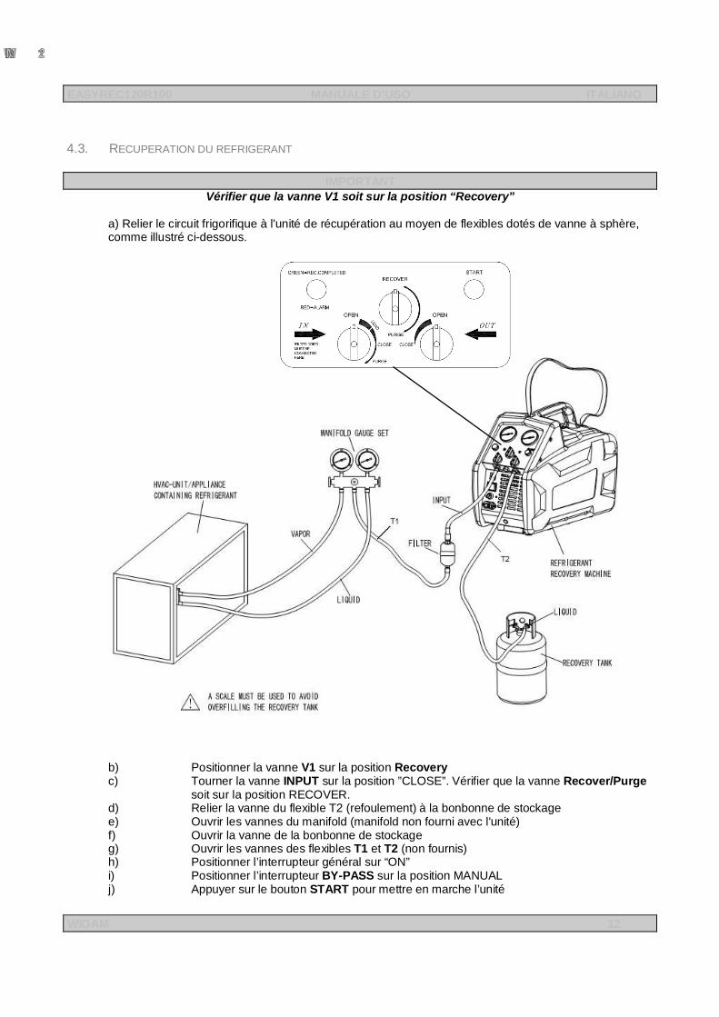
IMPORTANT Vérifier que la vanne V1 soit sur la position “Recovery/Recycling”
a) Relier le circuit frigorifique à l'unité de récupération au moyen de flexibles dotés de vanne à sphère, comme illustré ci-dessous.
EASYREC120R100 MANUALE D’USO ITALIANO
WIGAM 11
IMPORTANT - ATTENTION
En cas de récupérations/recyclages de grandes quantités de réfrigérant liquide (quantité supérieure à 2kg), régler le flux du réfrigérant en entrée en tournant la vanne INPUT VALVE de manière à ce que la pression indiquée sur le manomètre M1 ne dépasse pas 6 bar.
b) Positionner la vanne V1 sur Recovery/Recycling c) Tourner la vanne INPUT sur la position ”CLOSE”. Vérifier que la vanne Recover/Purge
soit sur la position RECOVER. d) Relier la vanne du flexible T2 (refoulement) à la bonbonne de stockage e) Ouvrir les vannes du manifold (manifold non fourni avec l'unité) f) Ouvrir la vanne de la bonbonne de stockage g) Ouvrir les vannes des flexibles T1 et T2 (non fournis) h) Positionner l’interrupteur général sur “ON” i) Positionner l’interrupteur BY-PASS sur la position « MANUAL » j) Tourner la vanne OUPUT sur la position “OPEN k) Tourner lentement la vanne INPUT sur la position “OPEN”. l) Appuyer sur le bouton START pour mettre en marche l’unité m) En cas de récupérations/recyclages de grandes quantités de réfrigérant liquide (quantité
supérieure à 2kg), régler le flux du réfrigérant en entrée en tournant la vanne INPUT VALVE de manière à ce que la pression indiquée sur le manomètre M1 ne dépasse pas 6 bar.
n) Si l’unité ne démarre pas, tourner la vanne INPUT sur la position "CLOSE", ensuite faire démarrer l’unité en appuyant sur START et ouvrir la vanne INPUT lentement.
o) Faire fonctionner l’unité jusqu’à l’obtention d’une pression de 2 bar sur le manomètre M1. Eteindre l’unité avec le bouton Power switch
p) Relier le flexible de vidange huile à la vanne V3 située au dos de l’unité. q) Ouvrir lentement la vanne jusqu’à ce que toute l’huile à l’intérieur de l’unité soit
déchargée. Au terme de cette opération, tourner la vanne V3 en position de fermeture. r) Redémarrer la fonction de Récupération/Recyclage en appuyant sur le bouton START s) Faire fonctionner l’unité jusqu’à l’obtention du vide désiré ou jusqu’à ce que l’unité
s’arrête automatiquement (interrupteur BY-PASS en position “AUTO”). t) Fermer les sorties liquide et vapeur du manifold u) Positionner les vannes INPUT et OUTPUT sur “CLOSE” v) Eteindre l’unité de récupération.
ATTENTION Toujours bien “drainer” l’unité après chaque utilisation. S’il reste du réfrigérant dans l’unité, cela peut provoquer la formation d’acide dans les composants internes et par conséquent causer des problèmes prématurés à l’unité.
EASYREC120R100 MANUALE D’USO ITALIANO
WIGAM 12
4.3. RECUPERATION DU REFRIGERANT
IMPORTANT Vérifier que la vanne V1 soit sur la position “Recovery”
a) Relier le circuit frigorifique à l'unité de récupération au moyen de flexibles dotés de vanne à sphère, comme illustré ci-dessous.
b) Positionner la vanne V1 sur la position Recovery c) Tourner la vanne INPUT sur la position ”CLOSE”. Vérifier que la vanne Recover/Purge
soit sur la position RECOVER. d) Relier la vanne du flexible T2 (refoulement) à la bonbonne de stockage e) Ouvrir les vannes du manifold (manifold non fourni avec l'unité) f) Ouvrir la vanne de la bonbonne de stockage g) Ouvrir les vannes des flexibles T1 et T2 (non fournis) h) Positionner l’interrupteur général sur “ON” i) Positionner l’interrupteur BY-PASS sur la position MANUAL j) Appuyer sur le bouton START pour mettre en marche l’unité
EASYREC120R100 MANUALE D’USO ITALIANO
WIGAM 13
k) Tourner la vanne OUPUT sur la position “OPEN” l) Ouvrir lentement la vanne INPUT. m) En présence de réfrigérant liquide, positionner la vanne INPUT de manière à ne pas
dépasser la zone “Liquide” n) Si le compresseur commence à faire du bruit, tourner lentement la vanne INPUT dans le
sens contraire des aiguilles d’une montre jusqu’à ce que le bruit cesse. o) Si l’unité n’a pas démarré ou si elle s’est arrêtée à cause d’une quantité excessive de
liquide à l’intérieur du compresseur, tourner la vanne INPUT sur la position "CLOSE" et ensuite faire redémarrer l’unité en appuyant sur la touche START; ouvrir ensuite la vanne INPUT lentement.
p) Si l'unité s’arrête automatiquement à la fin du cycle, positionner l’interrupteur BY-PASS sur la position “AUTO”
q) Au terme de la récupération du réfrigérant liquide, ouvrir complètement la vanne INPUT ainsi que les sorties liquide et vapeur du manifold, lesquelles peuvent améliorer la vitesse de récupération du réfrigérant liquide.
r) Faire fonctionner l’unité jusqu’à l’obtention du vide désiré ou jusqu’à ce que l’unité s’arrête automatiquement (interrupteur BY-PASS en position “AUTO”)
s) Fermer les sorties liquide et vapeur du manifold t) Positionner les vannes INPUT et OUTPUT sur “CLOSE” u) Eteindre l’unité de récupération.
ATTENTION
Toujours bien “drainer” l’unité après chaque utilisation. S’il reste du réfrigérant dans l’unité, cela peut provoquer la formation d’acide dans les composants internes et par conséquent causer des problèmes prématurés à l’unité.
EASYREC120R100 MANUALE D’USO ITALIANO
WIGAM 14
5. Procédure “Self-purge” 5.1. AVERTISSEMENTS
Lorsque le filtre déshydrateur a été utilisé avec un type de réfrigérant, il en reste très imprégné; de ce fait, avant d'utiliser l'unité de récupération avec un réfrigérant différent, il est nécessaire de remplacer le filtre déshydrateur et éliminer le réfrigérant résidu de l'intérieur de l'unité.
5.2. FONCTION “PURGE”
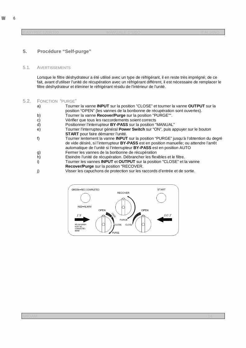
a) Tourner la vanne INPUT sur la position ”CLOSE” et tourner la vanne OUTPUT sur la position “OPEN” (les vannes de la bonbonne de récupération sont ouvertes).
b) Tourner la vanne Recover/Purge sur la position "PURGE"". c) Vérifier que tous les raccordements soient corrects d) Positionner l’interrupteur BY-PASS sur la position “MANUAL” e) Tourner l’interrupteur général Power Switch sur “ON”, puis appuyer sur le bouton
START pour faire démarrer l’unité. f) Tourner lentement la vanne INPUT sur la position “PURGE” jusqu’à l’obtention du degré
de vide désiré, si l’interrupteur BY-PASS est en position manuelle; ou attendre l’arrêt automatique de l’unité si l’interrupteur BY-PASS est en position AUTO
g) Fermer les vannes de la bonbonne de récupération h) Eteindre l’unité de récupération. Débrancher les flexibles et le filtre. i) Tourner les vannes INPUT et OUTPUT sur la position "CLOSE" et la vanne
Recover/Purge sur la position "RECOVER. j) Visser les capuchons de protection sur les raccords d’entrée et de sortie.
EASYREC120R100 MANUALE D’USO ITALIANO
WIGAM 15
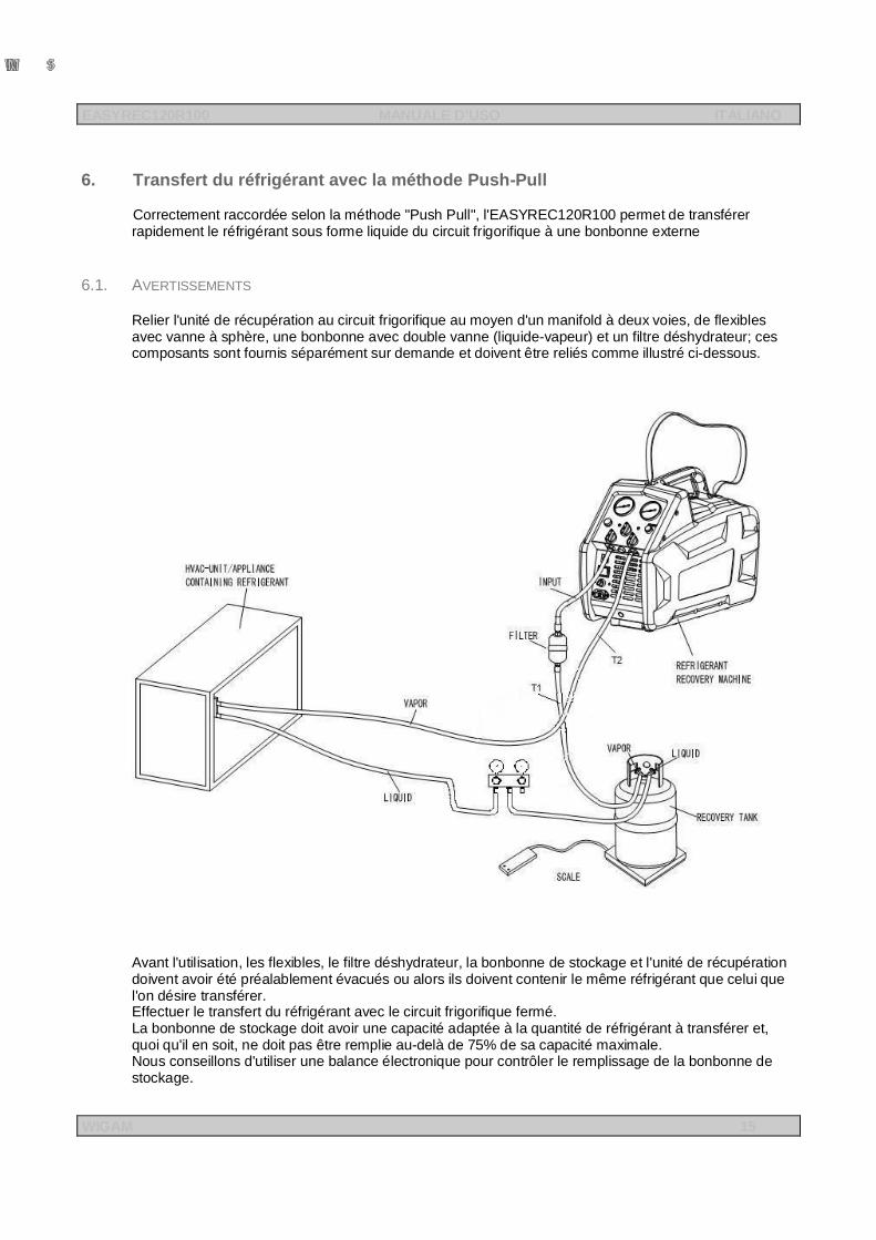
6. Transfert du réfrigérant avec la méthode Push-Pull
Correctement raccordée selon la méthode "Push Pull", l'EASYREC120R100 permet de transférer rapidement le réfrigérant sous forme liquide du circuit frigorifique à une bonbonne externe
6.1. AVERTISSEMENTS
Relier l'unité de récupération au circuit frigorifique au moyen d'un manifold à deux voies, de flexibles avec vanne à sphère, une bonbonne avec double vanne (liquide-vapeur) et un filtre déshydrateur; ces composants sont fournis séparément sur demande et doivent être reliés comme illustré ci-dessous.
Avant l'utilisation, les flexibles, le filtre déshydrateur, la bonbonne de stockage et l'unité de récupération doivent avoir été préalablement évacués ou alors ils doivent contenir le même réfrigérant que celui que l'on désire transférer. Effectuer le transfert du réfrigérant avec le circuit frigorifique fermé. La bonbonne de stockage doit avoir une capacité adaptée à la quantité de réfrigérant à transférer et, quoi qu'il en soit, ne doit pas être remplie au-delà de 75% de sa capacité maximale. Nous conseillons d'utiliser une balance électronique pour contrôler le remplissage de la bonbonne de stockage.
EASYREC120R100 MANUALE D’USO ITALIANO
WIGAM 16
6.2. TRANSFERT DU REFRIGERANT
a) Opérer sur le circuit de façon à ce que la plupart du réfrigérant soit pompé dans le récipient de liquide du système.
b) Au moyen de flexibles avec vanne à sphère, relier le manifold au raccord du récipient de liquide du circuit frigorifique et à la vanne de liquide (avec dispositif amorçant) de la bonbonne de stockage (voir dessin).
c) Relier le filtre déshydrateur (IN) de l’unité de récupération à la vanne vapeur (vanne sans dispositif amorçant) de la bonbonne de stockage, au moyen d’un flexible (T1) avec vanne à sphère
d) Relier le raccord de sortie (OUT) de l’unité de récupération au raccord vapeur du système A/C au moyen d’une flexible (T2)
e) Vérifier que la vanne V1 soit sur la position 1 Recovery f) Ouvrir les vannes INPUT et OUTPUT g) Ouvrir les vannes des flexibles T1 et T2 h) Ouvrir les vannes à sphère des flexibles T1 et T2 i) Ouvrir les vannes sur le manifold j) Ouvrir les vannes de la bonbonne de stockage k) Tourner l’interrupteur général power switch sur “ON”, et appuyer sur le bouton START pour
faire démarrer l’unité. Observer le voyant de passage du manifold; le transfert du réfrigérant du récipient de liquide à la bonbonne de stockage est terminé lorsque l'on ne voit plus passer de réfrigérant liquide dans le voyant
l) Une fois le transfert du réfrigérant terminé, fermer la vanne vapeur de la bonbonne (vanne sans
dispositif amorçant) m) Fermer la vanne du flexible T1 et attendre que sur le manomètre de basse pression M1 l'on lise
une pression de -0.2 bar (ou attendre que l’unité s’arrête automatiquement se l’interrupteur BY-PASS est sur la position AUTO)
n) Eteindre l’unité de récupération (interrupteur général sur “OFF“) o) Fermer la vanne liquide de la bonbonne et la vanne à sphère du flexible qui y est relié p) Fermer la vanne du flexible T2 q) Fermer toutes les vannes du manifold et des flexibles utilisés pour les raccordements Les résidus de réfrigérant gazeux peuvent être récupérés du circuit frigorifique en connectant l'unité comme illustré aux points "4.2/4.3 Récupération et recyclage du réfrigérant"
EASYREC120R100 MANUALE D’USO ITALIANO
WIGAM 17
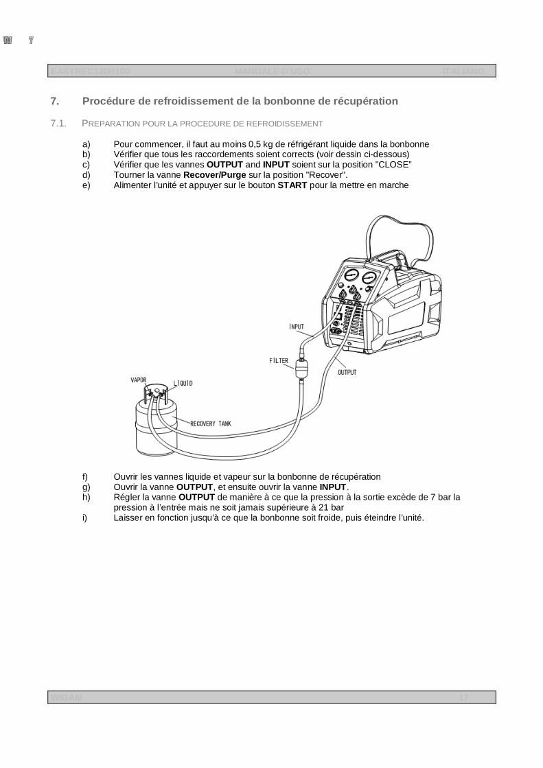
7. Procédure de refroidissement de la bonbonne de récupération
7.1. PREPARATION POUR LA PROCEDURE DE REFROIDISSEMENT a) Pour commencer, il faut au moins 0,5 kg de réfrigérant liquide dans la bonbonne b) Vérifier que tous les raccordements soient corrects (voir dessin ci-dessous) c) Vérifier que les vannes OUTPUT and INPUT soient sur la position ”CLOSE” d) Tourner la vanne Recover/Purge sur la position "Recover". e) Alimenter l’unité et appuyer sur le bouton START pour la mettre en marche
f) Ouvrir les vannes liquide et vapeur sur la bonbonne de récupération g) Ouvrir la vanne OUTPUT, et ensuite ouvrir la vanne INPUT. h) Régler la vanne OUTPUT de manière à ce que la pression à la sortie excède de 7 bar la
pression à l’entrée mais ne soit jamais supérieure à 21 bar i) Laisser en fonction jusqu’à ce que la bonbonne soit froide, puis éteindre l’unité.
EASYREC120R100 MANUALE D’USO ITALIANO
WIGAM 18
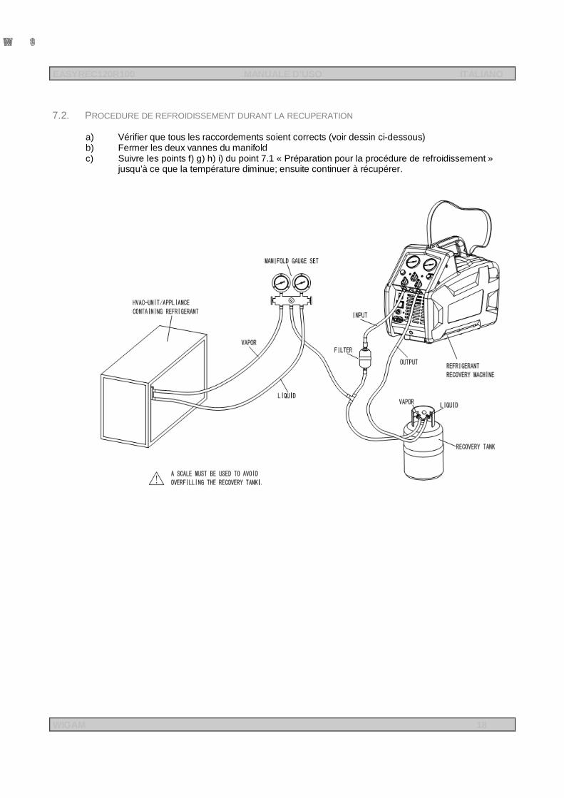
7.2. PROCEDURE DE REFROIDISSEMENT DURANT LA RECUPERATION
a) Vérifier que tous les raccordements soient corrects (voir dessin ci-dessous) b) Fermer les deux vannes du manifold c) Suivre les points f) g) h) i) du point 7.1 « Préparation pour la procédure de refroidissement »
jusqu’à ce que la température diminue; ensuite continuer à récupérer.
EASYREC120R100 MANUALE D’USO ITALIANO
WIGAM 19
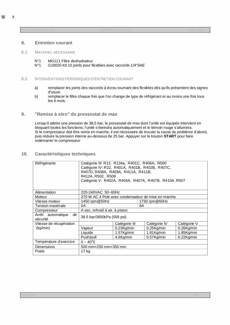
8. Entretien courant
8.1. MATERIEL NECESSAIRE
N°1 MG111 Filtre deshydrateur N°1 G19020 Kit 10 joints pour flexibles avec raccords 1/4"SAE
8.2. INTERVENTIONS PERIODIQUES D'ENTRETIEN COURANT
a) remplacer les joints des raccords à écrou tournant des flexibles dès qu'ils présentent des signes d'usure.
b) remplacer le filtre chaque fois que l'on change de type de réfrigérant et au moins une fois tous les 6 mois.
9. "Remise à zéro" du pressostat de max Lorsqu’il atteint une pression de 38,5 bar, le pressostat de max dont l’unité est équipée intervient en bloquant toutes les fonctions; l’unité s’éteindra automatiquement et le témoin rouge s’allumera. Si le compresseur doit être remis en marche, il est nécessaire de trouver la cause du problème d’abord, puis réduire la pression interne au-dessous de 25 bar. Appuyer sur le bouton START pour faire redémarrer le compresseur
10. Caractéristiques techniques Réfrigérants Catégorie III: R12, R134a, R401C, R406A, R500
Catégorie IV: R22, R401A, R401B, R402B, R407C, R407D, R408A, R409A, R411A, R411B, R412A, R502, R509 Catégorie V: R402A, R404A, R407A, R407B, R410A, R507
Alimentation 220-240VAC 50~60Hz Moteur 370 W AC 4 Pole avec condensateur de mise en marche Vitesse moteur 1450 rpm@50Hz 1750 rpm@60Hz Tension maximale 5A 8A Compresseur A sec, refroidi à air, à piston Arrêt automatique de sécurité 38.5 bar/3850kPa (558 psi)
Vitesse de récupération (kg/min)
Catégorie III Catégorie IV Catégorie V Vapeur 0.23Kg/min 0.25Kg/min 0.26Kg/min Liquide 1.57Kg/min 1.81Kg/min 1.85Kg/min Push/pull 4.6Kg/min 5.57Kg/min 6.22Kg/min
Température d’exercice 0 ~ 40℃ Dimensions 500 mm×250 mm×350 mm Poids 17 kg
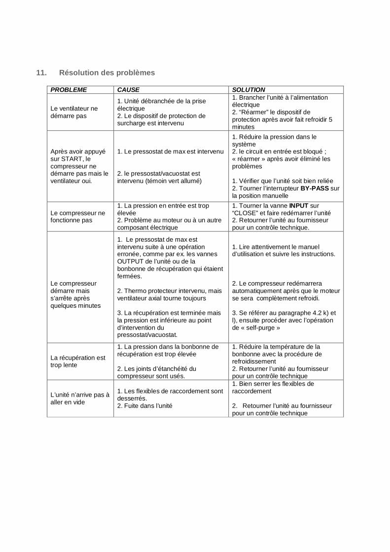
11. Résolution des problèmes
PROBLEME CAUSE SOLUTION
Le ventilateur ne démarre pas
1. Unité débranchée de la prise électrique 2. Le dispositif de protection de surcharge est intervenu
1. Brancher l’unité à l’alimentation électrique 2. “Réarmer” le dispositif de protection après avoir fait refroidir 5 minutes
Après avoir appuyé sur START, le compresseur ne démarre pas mais le ventilateur oui.
1. Le pressostat de max est intervenu 2. le pressostat/vacuostat est intervenu (témoin vert allumé)
1. Réduire la pression dans le système 2. le circuit en entrée est bloqué ; « réarmer » après avoir éliminé les problèmes 1. Vérifier que l’unité soit bien reliée 2. Tourner l’interrupteur BY-PASS sur la position manuelle
Le compresseur ne fonctionne pas
1. La pression en entrée est trop élevée 2. Problème au moteur ou à un autre composant électrique
1. Tourner la vanne INPUT sur “CLOSE” et faire redémarrer l’unité 2. Retourner l’unité au fournisseur pour un contrôle technique.
Le compresseur démarre mais s’arrête après quelques minutes
1. Le pressostat de max est intervenu suite à une opération erronée, comme par ex. les vannes OUTPUT de l’unité ou de la bonbonne de récupération qui étaient fermées. 2. Thermo protecteur intervenu, mais ventilateur axial tourne toujours 3. La récupération est terminée mais la pression est inférieure au point d’intervention du pressostat/vacuostat.
1. Lire attentivement le manuel d’utilisation et suivre les instructions. 2. Le compresseur redémarrera automatiquement après que le moteur se sera complètement refroidi. 3. Se référer au paragraphe 4.2 k) et l), ensuite procéder avec l’opération de « self-purge »
La récupération est trop lente
1. La pression dans la bonbonne de récupération est trop élevée 2. Les joints d’étanchéité du compresseur sont usés.
1. Réduire la température de la bonbonne avec la procédure de refroidissement 2. Retourner l’unité au fournisseur pour un contrôle technique
L’unité n’arrive pas à aller en vide
1. Les flexibles de raccordement sont desserrés. 2. Fuite dans l’unité
1. Bien serrer les flexibles de raccordement 2. Retourner l’unité au fournisseur pour un contrôle technique
EASYREC120 USER’S MANUAL ENGLISH
WIGAM 21
WIGAM S.p.A. reserves the right to discontinue, or change at any time specifications or designs without notice and without incurring obligations according to her policy of always improving her products. Layout: WIGAM S.p.A. Printed in Italy 1st edition: Jan 2010
EASYREC120 USER’S MANUAL ENGLISH
WIGAM 22
INDEX Hydraulic diagram................................................................................................................. 23 Wiring diagram ..................................................................................................................... 24 Safety precautions and Operation guidelines .................................................................... 25 1. Introduction to the recovery unit EASYREC120R100 ................................................. 27 2. Standard equipment and components description .................................................... 27
2.1. Recovery compressor ................................................................................................................................ 27 2.2. Filter ............................................................................................................................................................ 27 2.3. Moisture indicator ....................................................................................................................................... 27 2.4. Pressure gauges ........................................................................................................................................ 27 2.5. Distillation system ....................................................................................................................................... 27
3. Control panel.................................................................................................................. 28 4. Refrigerant recovery from the A/C system .................................................................. 30
4.1. Warning ....................................................................................................................................................... 30 4.2. Refrigerant recovery/recycling ................................................................................................................... 30 4.3. Refrigerant recovery ................................................................................................................................... 32
5. Self-Purge Method ......................................................................................................... 34 5.1. Warning ....................................................................................................................................................... 34 5.2. “Purge” function .......................................................................................................................................... 34
6. Refrigerant Transfer with Push-Pull method ............................................................... 35 6.1. Warning ....................................................................................................................................................... 35 6.2. Refrigerant transfer .................................................................................................................................... 36
7. Recovery cylinder cooling method .............................................................................. 37 7.1. Pre-work Cooling method .......................................................................................................................... 37 7.2. Cylinder Cooling Procedure in the recovering process ........................................................................... 38
8. Ordinary maintenance ................................................................................................... 39 8.1. Spare parts and accessories ..................................................................................................................... 39 8.2. Periodical operations for ordinary maintenance ....................................................................................... 39
9. Max pressure switch reset ............................................................................................ 39 10. Technical features ...................................................................................................... 39 11. Troubleshooting ......................................................................................................... 40
EASYREC120 USER’S MANUAL ENGLISH
WIGAM 23
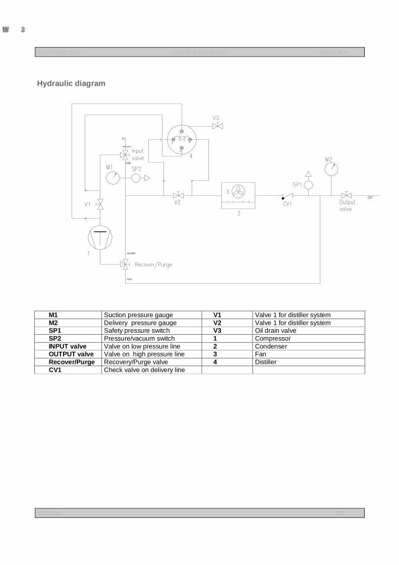
Hydraulic diagram
M1 Suction pressure gauge V1 Valve 1 for distiller system M2 Delivery pressure gauge V2 Valve 1 for distiller system SP1 Safety pressure switch V3 Oil drain valve SP2 Pressure/vacuum switch 1 Compressor INPUT valve Valve on low pressure line 2 Condenser OUTPUT valve Valve on high pressure line 3 Fan Recover/Purge Recovery/Purge valve 4 Distiller CV1 Check valve on delivery line
EASYREC120 USER’S MANUAL ENGLISH
WIGAM 24
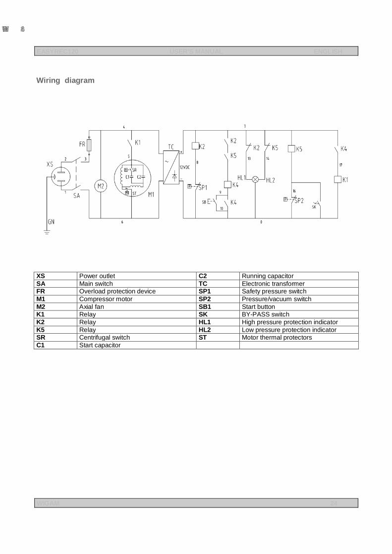
Wiring diagram
XS Power outlet C2 Running capacitor SA Main switch TC Electronic transformer FR Overload protection device SP1 Safety pressure switch M1 Compressor motor SP2 Pressure/vacuum switch M2 Axial fan SB1 Start button K1 Relay SK BY-PASS switch K2 Relay HL1 High pressure protection indicator K5 Relay HL2 Low pressure protection indicator SR Centrifugal switch ST Motor thermal protectors C1 Start capacitor
EASYREC120 USER’S MANUAL ENGLISH
WIGAM 25
WARNING
Safety precautions and Operation guidelines
a) Read all safety, operating guidelines and instructions before operating this unit. b) Only a qualified technician should operate this recovery unit! c) Always wear safety glasses and protective gloves while working with refrigerants to protect your
eyes and skin from refrigerant gases and refrigerant liquid. Avoid getting in touch with caustic liquid or gas.
d) Do not expose the equipment to the sun or rain. e) Be sure that any room where you are working is thoroughly ventilated. f) Use ONLY authorized refillable refrigerant cylinders. It requires the use of recovery cylinders
with a minimum working pressure of 27.6 bar. g) Do not overfill the recovery cylinder. Cylinder is full at 75% capacity. There should be enough
space for liquid expansion. Overfilling of the cylinder may cause a violent explosion. h) Do not exceed the working pressure of the recovery cylinder cylinder. i) Do not mix different refrigerants together in one cylinder, or they could not be separated or used. j) Before recovering the refrigerant, the cylinder should achieve the vacuum level: -0.9 MPa, which
is for purging non-condensable gases. k) When the unit is not used, all valves should be closed and the input and output fittings should be
covered with their protective caps, as air and/or moisture may damage the recovery performances and shorten the service life of compressor.
l) If using an extension power cord, it should be a minimum 2.0mm2 wires section and no longer than 30 meters, or it may make the voltage drop and damage the compressor.
m) A filter drier must always be used and should be replaced frequently. Each type of refrigerant must have its own filter. For the sake of ensuring the normal operation of the unit, please use the filter specified by our company. High quality filter drier will bring high quality services.
n) Special care should be taken while recovering from a "burned-out" system. Use two high acid capacity filters in series. When you have finished recovering from the system, flush the unit with a small amount of clean refrigerant and refrigerant oil to purge off foreign substances left inside.
o) The unit has an Internal High Pressure Shut Off Switch. If the pressure inside the system goes above 38.5 bar, the unit will automatically shut itself off and the Red Alarm Light will turn on. If the compressor needs to be restarted, please find out the cause first, then reduce the internal pressure below 25 bar. Press the START button to restart the compressor.
When the unit is under high pressure condition, restart the unit after eliminating the troubles Solutions for possible causes of High Pressure Shut Off:
1. Open the output valve of the unit if it's closed. 2. Open the input valve of the recovery cylinder if it's closed. 3. Check if the hose connected between the unit and the recovery cylinder is jammed. If yes, please
close the output valve of the unit and the input valve of the recovery cylinder and then change a new one.
4. The temperature and the pressure of the recovery cylinder is too high (see recovery cylinder cooling method) p) While using the recovery unit, make sure the power of the air-conditioning system is off q) The unit has an Internal Low Pressure Shut Off Switch (Pressure/vacuum switch). The unit will
automatically shut itself off if the inner pressure is lower than -0.2 ÷ -0.4bar and the green alarm light will turn on. To restart the compressor, please increase the input pressure above +0.4 bar or rotate the “BY-PASS switch” to the MANUAL position, then press the START button.
r) BY-PASS switch : - when the BY-PASS switch is on AUTO, the pressure/vacuum switch can work, - when the BY-PASS switch is on MANUAL, the pressure/vacuum switch can’t work. Please turn to the “Manual” position when the system pressure is lower than +0.4 bar or the system needs high vacuum.
s) If the cylinder pressure exceeds 21 bar, use the Recovery Cylinder Cooling Method to reduce the cylinder pressure.
EASYREC120 USER’S MANUAL ENGLISH
WIGAM 26
t) To maximize recovery rates, use the shortest possible length of 3/8" or larger hose. u) While recovering large amounts of liquid, use the liquid Push/Pull method. v) After recovering, make sure there is no refrigerant left in the unit. Read the Self-Purging Method
carefully. If liquid refrigerant remains in the unit, it can expand and damage the components. w) If the unit is to be stored or not used for any length of time, we recommend that it be completely
evacuated of any residual refrigerant and purged with dry nitrogen. x) We suggest to use the hose with valve in order to reduce the loss of the refrigerant
EASYREC120 USER’S MANUAL ENGLISH
WIGAM 27
1. Introduction to the recovery unit EASYREC120R100 Considering its reduced volume and the extreme facility of transportation, the unit is suited for interventions on civil conditioners, automotive vehicle conditioners, dispensers, domestic and commercial refrigerators and dehumidifiers. The unit is supplied with an oil-less compressor without lubricant.
2. Standard equipment and components description
2.1. RECOVERY COMPRESSOR
Unit EASYREC120R100 is equipped with an oil-less compressor and is suitable for any type of CFC, HCFC and HFC refrigerant.
2.2. FILTER The filter is equipped with two 1/4sae male connections. It is supplied with a hose to make the connection easier. The unit is also equipped with a moisture indicator that allows to check the quality of the filter.
2.3. MOISTURE INDICATOR The moisture indicator must be connected between the filter and the recovery unit. It allows to check the quality of the filter. Replace the filter whenever the indicator shows that there is moisture.
2.4. PRESSURE GAUGES
Unit EASYREC120R100 is equipped with two oil-filled pressure gauges Ø60mm: one pressure gauge on the suction line and one on the discharge line. They allow to check the pressure during recovery and refrigerant transfer with the push-pull method.
2.5. DISTILLATION SYSTEM Unit EASYREC120R100 is provided with a distillation system (that can be excluded): it is equipped with an automatic device for flow regulation and allows the complete separation of the oil (coming from the system) from the refrigerant.
WARNING This equipment must NOT work for more than 10 minutes in vacuum (-0.02Mpa) when the BY-PASS
switch” is on the MANUAL position
EASYREC120 USER’S MANUAL ENGLISH
WIGAM 28
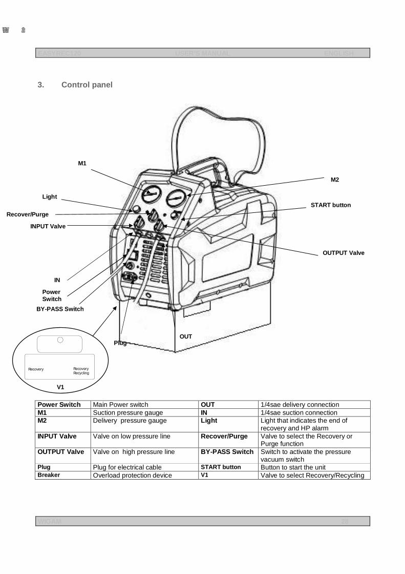
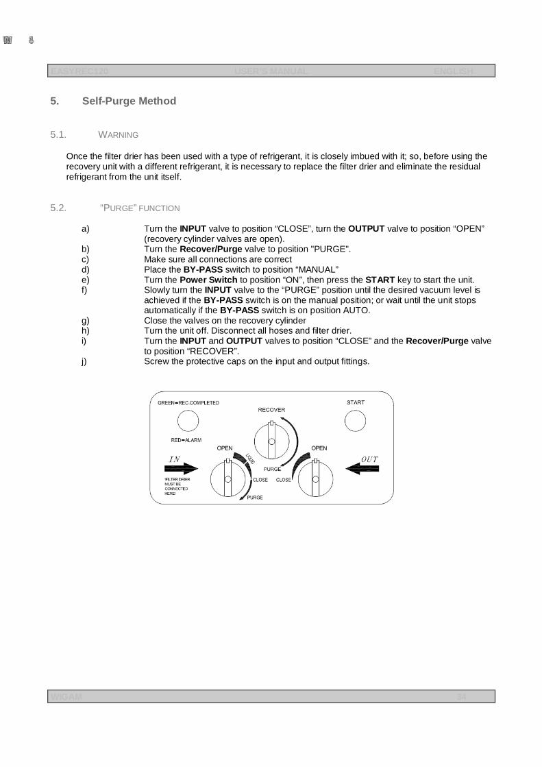
3. Control panel
Power Switch Main Power switch OUT 1/4sae delivery connection M1 Suction pressure gauge IN 1/4sae suction connection M2 Delivery pressure gauge Light Light that indicates the end of
recovery and HP alarm INPUT Valve Valve on low pressure line Recover/Purge Valve to select the Recovery or
Purge function OUTPUT Valve Valve on high pressure line BY-PASS Switch Switch to activate the pressure
vacuum switch Plug Plug for electrical cable START button Button to start the unit Breaker Overload protection device V1 Valve to select Recovery/Recycling
M2
START button
OUTPUT Valve
OUT
IN
INPUT Valve
M1
Light
Recover/Purge
Power Switch
BY-PASS Switch
Plug
RecoveryRecoveryRecycling
V1

EASYREC120 USER’S MANUAL ENGLISH
WIGAM 29

EASYREC120 USER’S MANUAL ENGLISH
WIGAM 30
4. Refrigerant recovery from the A/C system
4.1. WARNING
To recover the refrigerant in a quick and efficient way, we suggest to connect the recovery unit to the cooling system by means of a 2-way manifold and flexible hoses with ball valves, which are not included in the standard equipment. Before starting refrigerant recovery, the manifold, the flexible hoses and the filter drier must have been previously evacuated. During refrigerant recovery, the cooling system must be turned off.
4.2. REFRIGERANT RECOVERY/RECYCLING
IMPORTANT Make sure that the V1 valve is on position “Recovery/Recycling”
a) Connect the refrigerant circuit to the recovery unit by means of flexible hoses with ball valve, as shown by the picture.
EASYREC120 USER’S MANUAL ENGLISH
WIGAM 31
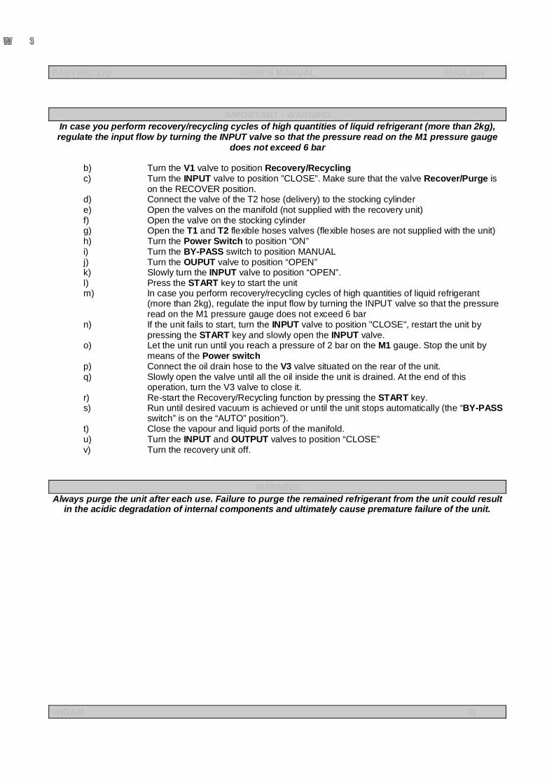
IMPORTANT - WARNING
In case you perform recovery/recycling cycles of high quantities of liquid refrigerant (more than 2kg), regulate the input flow by turning the INPUT valve so that the pressure read on the M1 pressure gauge
does not exceed 6 bar b) Turn the V1 valve to position Recovery/Recycling c) Turn the INPUT valve to position ”CLOSE”. Make sure that the valve Recover/Purge is
on the RECOVER position. d) Connect the valve of the T2 hose (delivery) to the stocking cylinder e) Open the valves on the manifold (not supplied with the recovery unit) f) Open the valve on the stocking cylinder g) Open the T1 and T2 flexible hoses valves (flexible hoses are not supplied with the unit) h) Turn the Power Switch to position “ON” i) Turn the BY-PASS switch to position MANUAL j) Turn the OUPUT valve to position “OPEN” k) Slowly turn the INPUT valve to position “OPEN”. l) Press the START key to start the unit m) In case you perform recovery/recycling cycles of high quantities of liquid refrigerant
(more than 2kg), regulate the input flow by turning the INPUT valve so that the pressure read on the M1 pressure gauge does not exceed 6 bar
n) If the unit fails to start, turn the INPUT valve to position "CLOSE", restart the unit by pressing the START key and slowly open the INPUT valve.
o) Let the unit run until you reach a pressure of 2 bar on the M1 gauge. Stop the unit by means of the Power switch
p) Connect the oil drain hose to the V3 valve situated on the rear of the unit. q) Slowly open the valve until all the oil inside the unit is drained. At the end of this
operation, turn the V3 valve to close it. r) Re-start the Recovery/Recycling function by pressing the START key. s) Run until desired vacuum is achieved or until the unit stops automatically (the “BY-PASS
switch” is on the “AUTO” position”). t) Close the vapour and liquid ports of the manifold. u) Turn the INPUT and OUTPUT valves to position “CLOSE” v) Turn the recovery unit off.
WARNING Always purge the unit after each use. Failure to purge the remained refrigerant from the unit could result
in the acidic degradation of internal components and ultimately cause premature failure of the unit.
EASYREC120 USER’S MANUAL ENGLISH
WIGAM 32
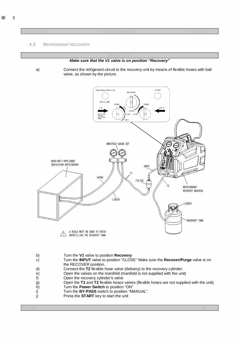
4.3. REFRIGERANT RECOVERY
IMPORTANT Make sure that the V1 valve is on position “Recovery”
a) Connect the refrigerant circuit to the recovery unit by means of flexible hoses with ball
valve, as shown by the picture.
b) Turn the V1 valve to position Recovery c) Turn the INPUT valve to position “CLOSE” Make sure the Recover/Purge valve is on
the RECOVER position. d) Connect the T2 flexible hose valve (delivery) to the recovery cylinder. e) Open the valves on the manifold (manifold is not supplied with the unit) f) Open the recovery cylinder’s valve g) Open the T1 and T2 flexible hoses valves (flexible hoses are not supplied with the unit) h) Turn the Power Switch to position “ON” i) Turn the BY-PASS switch to position “MANUAL” j) Press the START key to start the unit
EASYREC120 USER’S MANUAL ENGLISH
WIGAM 33
k) Turn the OUTPUT valve to position “OPEN” l) Slowly open the INPUT valve. m) In the presence of liquid refrigerant, place the INPUT valve so that it does not go beyond
the “liquid” zone n) If the compressor starts to knock, slowly throttle back the INPUT valve until the knocking
stops. o) If the unit fails to start or has stopped due to an excessive quantity of liquid inside the
compressor, please turn the INPUT valve to position "CLOSE", and then start the unit by pressing the START key; then slowly open the INPUT valve.
p) If you want the unit to stop automatically at the end of the cycle, turn the BY-PASS switch to position “AUTO”.
q) When finishing the liquid refrigerant recovery, completely open the INPUT valve and the vapour and liquid ports of the manifold; this can improve the liquid recovery speed.
r) Run until desired vacuum is achieved or until the unit stops automatically (the BY-PASS switch is on the “AUTO” position).
s) Close the vapour and liquid ports of the manifold. t) Turn the INPUT and OUTPUT valves to position “CLOSE” u) Turn the recovery unit off.
WARNING Always purge the unit after each use. Failure to purge the remained refrigerant from the unit could result
in the acidic degradation of internal components and ultimately cause premature failure of the unit.
EASYREC120 USER’S MANUAL ENGLISH
WIGAM 34
5. Self-Purge Method
5.1. WARNING
Once the filter drier has been used with a type of refrigerant, it is closely imbued with it; so, before using the recovery unit with a different refrigerant, it is necessary to replace the filter drier and eliminate the residual refrigerant from the unit itself.
5.2. “PURGE” FUNCTION
a) Turn the INPUT valve to position “CLOSE”, turn the OUTPUT valve to position “OPEN” (recovery cylinder valves are open).
b) Turn the Recover/Purge valve to position "PURGE". c) Make sure all connections are correct d) Place the BY-PASS switch to position “MANUAL” e) Turn the Power Switch to position “ON”, then press the START key to start the unit. f) Slowly turn the INPUT valve to the “PURGE” position until the desired vacuum level is
achieved if the BY-PASS switch is on the manual position; or wait until the unit stops automatically if the BY-PASS switch is on position AUTO.
g) Close the valves on the recovery cylinder h) Turn the unit off. Disconnect all hoses and filter drier. i) Turn the INPUT and OUTPUT valves to position “CLOSE” and the Recover/Purge valve
to position “RECOVER”. j) Screw the protective caps on the input and output fittings.
EASYREC120 USER’S MANUAL ENGLISH
WIGAM 35
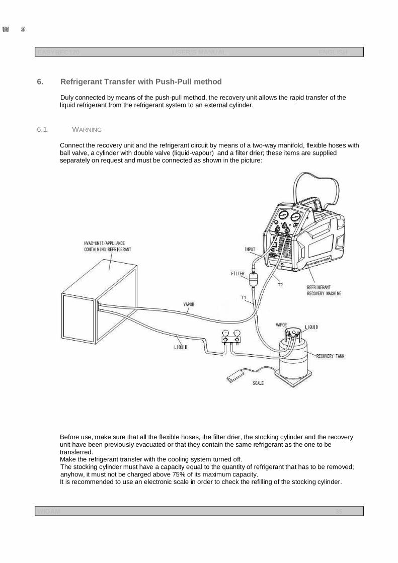
6. Refrigerant Transfer with Push-Pull method
Duly connected by means of the push-pull method, the recovery unit allows the rapid transfer of the liquid refrigerant from the refrigerant system to an external cylinder.
6.1. WARNING
Connect the recovery unit and the refrigerant circuit by means of a two-way manifold, flexible hoses with ball valve, a cylinder with double valve (liquid-vapour) and a filter drier; these items are supplied separately on request and must be connected as shown in the picture:
Before use, make sure that all the flexible hoses, the filter drier, the stocking cylinder and the recovery unit have been previously evacuated or that they contain the same refrigerant as the one to be transferred. Make the refrigerant transfer with the cooling system turned off. The stocking cylinder must have a capacity equal to the quantity of refrigerant that has to be removed; anyhow, it must not be charged above 75% of its maximum capacity. It is recommended to use an electronic scale in order to check the refilling of the stocking cylinder.
EASYREC120 USER’S MANUAL ENGLISH
WIGAM 36
6.2. REFRIGERANT TRANSFER
a) Operate on the refrigerant’s system in order that most part of the refrigerant will be pumped into the liquid side of the system.
b) By means of the flexible hoses with ball valve, connect the cooling system liquid receiver connection to the stocking cylinder liquid valve (with tube) (see the above picture)
c) By means of the flexible hose (T1) with ball valve, connect the recovery unit filter drier (IN) to the stocking cylinder vapour valve (valve without tube)
d) By means of a flexible hose (T2), connect the exit connection (OUT) of the recovery unit to the A/C system vapour connection
e) Make sure that V1 valve in on position 1 Recovery. f) Open the INPUT and OUTPUT valves of the recovery unit g) Open the valves of the flexible hoses T1 and T2 of the recovery unit h) Open the ball valves of the connecting flexible hoses i) Open the valves on the manifold j) Open the stocking cylinder valves k) Switch the Power Switch to position “ON”, then press the START key to start the unit.
Watch the manifold sightglass; the refrigerant transfer from the liquid receiver to the stocking cylinder is complete when you can see through the sightglass that the liquid refrigerant has stopped flowing.
l) When the refrigerant transfer has been completed, close the cylinder vapour valve (valve without tube)
m) Close the valve of the T1 hose and wait until you can read a pressure of -0.2 bar on the M1 low pressure gauge (or wait for the automatic stop of the unit if the BY-PASS switch is on the AUTO position)
n) Turn the recovery unit off (Power switch to position “OFF”) o) Close the cylinder liquid valve and the flexible hose ball valve connected to it. p) Close the valve of the T2 flexible hose q) Close all the manifold and flexible hoses valves used for connections
The recovery of the residual gaseous refrigerant from the inside refrigerant system can be done by connecting the unit as shown in “4.2 Refrigerant Recovery”
EASYREC120 USER’S MANUAL ENGLISH
WIGAM 37
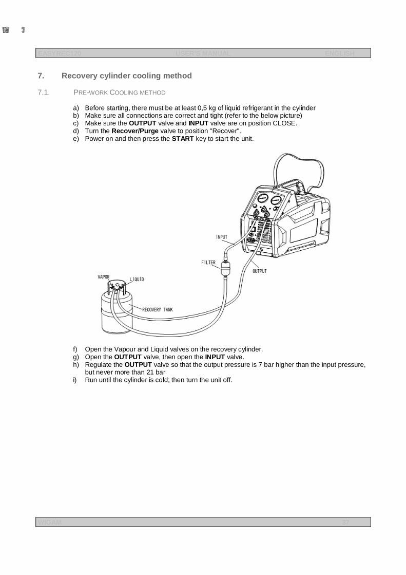
7. Recovery cylinder cooling method
7.1. PRE-WORK COOLING METHOD
a) Before starting, there must be at least 0,5 kg of liquid refrigerant in the cylinder b) Make sure all connections are correct and tight (refer to the below picture) c) Make sure the OUTPUT valve and INPUT valve are on position CLOSE. d) Turn the Recover/Purge valve to position "Recover". e) Power on and then press the START key to start the unit.
f) Open the Vapour and Liquid valves on the recovery cylinder. g) Open the OUTPUT valve, then open the INPUT valve. h) Regulate the OUTPUT valve so that the output pressure is 7 bar higher than the input pressure,
but never more than 21 bar i) Run until the cylinder is cold; then turn the unit off.
EASYREC120 USER’S MANUAL ENGLISH
WIGAM 38
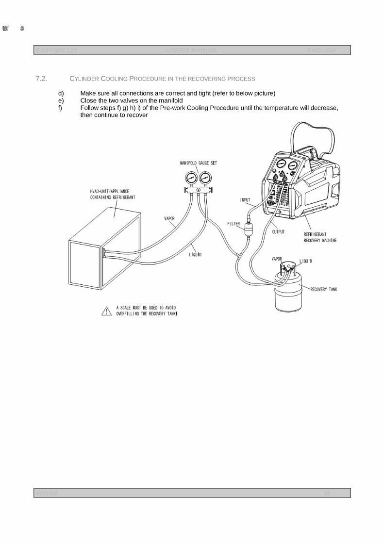
7.2. CYLINDER COOLING PROCEDURE IN THE RECOVERING PROCESS
d) Make sure all connections are correct and tight (refer to below picture) e) Close the two valves on the manifold f) Follow steps f) g) h) i) of the Pre-work Cooling Procedure until the temperature will decrease,
then continue to recover
EASYREC120 USER’S MANUAL ENGLISH
WIGAM 39
8. Ordinary maintenance
8.1. SPARE PARTS AND ACCESSORIES
n°1 MG111 Filter drier n°1 XH412 Filter drier n°1 G19020 Kit of 10 gaskets for flexible hose with ¼” SAE connections
8.2. PERIODICAL OPERATIONS FOR ORDINARY MAINTENANCE
a) Replace the swivel connections gaskets of the flexible hoses as soon as they show worn marks. b) Replace the filter each time a different type of refrigerant is used and at least once every six
months.
9. Max pressure switch reset When a pressure of 38,5 BAR is reached, the max pressure switch, which is in the unit, operates by restraining all functions; the unit will automatically shut itself off and the Red Alarm Light will turn on. If the compressor needs to be restarted, please find out the cause first, then reduce the internal pressure below 25 bar. Press the START key to restart the compressor.
10. Technical features
Refrigerants Category III: R12, R134a, R401C, R406A, R500 Category IV: R22, R401A, R401B, R402B, R407C, R407D, R408A, R409A, R411A, R411B, R412A, R502, R509 Category V: R402A, R404A, R407A, R407B, R410A, R507
Power 220-240VAC 50~60Hz Motor 370 W AC 4 Pole start capacitor running capacitor Motor speed 1450 rpm@50Hz 1750 rpm@60Hz Maximal current draw
5A 8A
Compressor Oil-less, air-cooled, piston Automatic safety shut-off 38.5 bar/3850kPa(558 psi)
Recovery rate (kg/min)
Category III Category IV Category V Vapor 0.23Kg/min 0.25Kg/min 0.26Kg/min Liquid 1.57Kg/min 1.81Kg/min 1.85Kg/min Push/pull 4.6Kg/min 5.57Kg/min 6.22Kg/min
Operating temperature 0 ~ 40℃
Dimensions 500 mm×250 mm×350 mm Weight 17 kg
11. Troubleshooting
PROBLEM CAUSE ACTION
Fan does not run 1.Power supply cord is not connected 2.The circuit breaker has cut off
1. Connect the power supply cord 2. Reset the circuit breaker when it’s cooling after 5 minutes
After pressing the START key, the compressor doesn't start but the fan runs
1.The unit is in high pressure shut off (Red alarm light turns on) 2.The unit is under low pressure protection (Green light turns on)
1. Reduce the system pressure 2. The input loop is blocked, reset after eliminating troubles 3. Check if well connected 4. Turn the BY-PASS switch to the restart position
The compressor can’t work
1.Output pressure is too high 2. Failure in the motor, or other electrical components
1.Turn the INPUT valve to position CLOSE and restart the unit 2. Factory service is required
The compressor starts but cuts off within a few minutes
1.High pressure shuts off due to wrong operation, such as output valves of the unit or recovery cylinder are not open 2.Thermal protector is disconnected, but axial fan still running 3.The recovery cylinder is full at 80% capacity 4. Recovery is over and the unit is under low pressure switching point
1. Read carefully this operating manual and follow the instructions, 2. The compressor will restart automatically after the motor is completely cooled 3. Take a new cylinder and then press the START key to start the compressor 4. Refer to step 4.2 k) and l), then proceed with self-purge operation
Recovery process is too slow
1.The pressure inside the recovery cylinder is too high 2.The compressor seals are worn out
1. Reduce the cylinder temperature with the Recovery Cylinder Cooling Method 2. Factory service is required
The unit doesn't pull out a vacuum
1.Connecting hoses are loose 2. There is a leakage in the unit
1.Tighten the connecting hoses 2. Factory service is required


Loc.Spedale 10/b 52018 Castel San Niccolò (AR) ITALY Tel. ++39-0575-5011 Fax. ++39-0575-501200
www.wigam.com - [email protected]