Proceedings of the 5th International Conference on Integrity-Reliability-Failure, Porto/Portugal 24-28 July 2016
Editors J.F. Silva Gomes and S.A. Meguid
Publ. INEGI/FEUP (2016)
-867-
PAPER REF: 6337
BIOMECHANICS OF LUMBAR SPINE
Catarina S. Mendes1, Luísa C. Sousa
2 (*), Marco Parente
2, Renato Natal Jorge
2, João M. Gonçalves
3,
Rolando Freitas4
1Universidade do Porto, Porto, Portugal 2Instituto de Engenharia Mecânica e Gestão Industrial (INEGI), Universidade do Porto, Porto, Portugal 3Serviço de Ortopedia, Hospital da Arrábida, Vila Nova de Gaia, Portugal 4Departmento de Cirurgia da Coluna, Serviço de Ortopedia - C. H. de Vila Nova de Gaia, Portugal (*)Email: [email protected]
ABSTRACT
The main goal of the presented study is to understand the mechanical behaviour of a lumbar
functional spine unit (FSU) L4-L5 with spondylolisthesis pathology. For the study of the
healthy FSU the process includes the 3D reconstruction of the lumbar spine geometry from
computer tomography (CT) images, finite element (FE) mesh definition and simulation of the
spine mechanics under different load cases. The pathological model was built applying a
posterior displacement of 6.81mm. The study of the two FE models, one healthy and the other
with pathology, allowed identifying significant differences on the mechanical behaviour.
Keywords: Biomechanics, finite elements method, lumbar spine, vertebrae L4-L5,
spondylolisthesis.
INTRODUCTION
Low back pain is the most diffuse pathology and represents one of the top causes of missed
work. This pain is a universal human experience as almost everyone has it at some point.
Fortunately, low back pain often gets better on its own. When it doesn't, there are effective
treatments.
Some authors (Weinstain, 2010; Moramarco, 2010) explain that low back pain can arise due
to idiopathic degeneration of any mechanical component of the column spine, like discs,
ligaments and facet joints. In most cases, surgery is the unique effective solution to the
problem. Surgery should only be considered if a patient's ability to participate in everyday
activities is unacceptably reduced and a concerted effort to relieve symptoms through non
operative techniques has been unproductive. Any treatment of lumbar spine injuries aims at
returning to a more active and pain free lifestyle, decreasing of any neurological deficit and
prevention of further disability. Furthermore, surgical treatment has some advantages like the
immediate stability and the possibility for early mobilization.
Nowadays most of the orthopaedic surgeries are essentially based on the experience of the
surgeon, who demands the best situation for each patient (Moramarco, 2010). Although CT
and magnetic resonance techniques allow the doctor to observe the current state of the patient
spine degeneration, it is not possible to predict the behaviour of the spine after surgery. The
use of computer models to study the biomechanical alterations of the cervical spine is a
powerful tool to understand the mechanisms of injury. The finite element method is an
excellent tool for studying the biomechanical behaviour of the spine, as it allows spine motion
analysis(Guan, 2006; Little, 2007); it makes possible to find the best solutions helping
Symposium_11: Advances in Cardiovascular and Orthopedics Biomechanics
-868-
clinicians to make the best decision in planning surgical interventions. In the last years,
several models were created, with the goal to create prosthesis for a particular problem,
(Eberlein, 2001; Guan, 2006; Little, 2007; Moramarco, 2010; Rodrigues 2012; , 2013).
The main goal of this study is to perform the development of a non-invasive method to obtain
truly dynamic behaviour of the spine under specific loads. A heathy model of a lumbar L4-L5
FSU is created and an iterative calibration process was performed in order to find an ideal but
realistic combination of mechanical properties. Then a pathological model is built applying a
posterior displacement equal to 6.81 mm, corresponding to a lumbar spondylolisthesis. Using
the commercial software Abaqus Explicit, the characterization of each FSU model is made in
order to compare the behaviour of the heathy and non-health FE models under different
loading types; results show that for the same load, stresses of the non-healthy intervertebral
disc are higher, which can lead to greater disc injury.
METHODS
The spinal segment L4-L5 under consideration consists of two vertebral bodies, the
intervertebral disc, spinal ligaments and facet joints. The intervertebral disc and ligaments
contribute to the general flexibility of this spinal segment, having an important role in the
spine kinematics. For the definition of the healthy FSU geometry, vertebrae, intervertebral
discs (nucleus pulpous, annulus fibrosus and fibres), endplates, ligaments and facet joints
were considered (Little, 2007).
The construction of the vertebrae was established using CT scan data, and the finite element
mesh of the vertebrae was created using the commercial finite element package Abaqus/Cae
(Rodrigues, 2012).
The intervertebral disc was designed with its components, such as nucleus pulposus and
annulus fibrosus bounded by two endplates (Jieun, 2012; Rodrigues, 2012). Due to its lower
density, the intervertebral discs are not visible in a CT and disc geometry was defined using
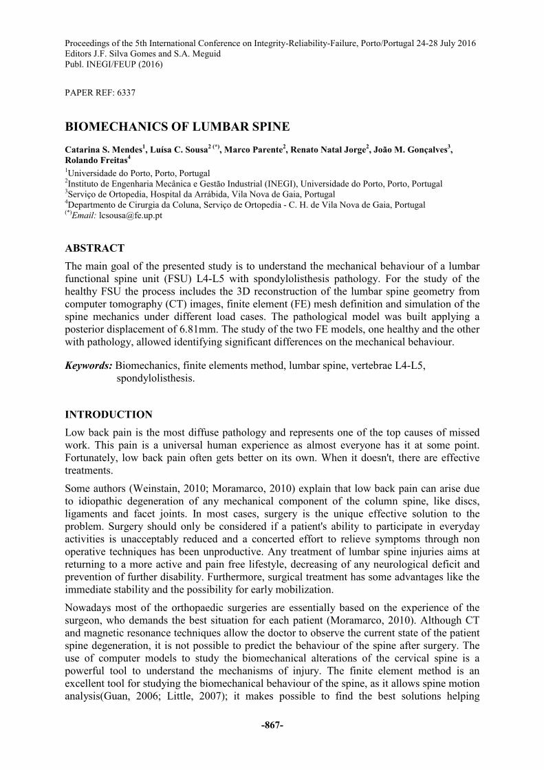
the lower surface of L4 and the upper surface of L5. Fig. 1 shows the disc geometry with the
two different regions, the inner nucleus pulposus and the peripheral annulus fibrosus taking
into account the volumetric ratio 3:7.
Fig. 1 - 3D finite element of the intervertebral disc and Layers 1-2 and 7-8 of collagen fibres
The annulus fibrosus is a viscous substance reinforced by a network of collagen fibres. The
arrangement of the elastic fibres plays a very important role in the overall mechanical
properties of the annulus fibrosus. The stiffness of the fibre proportionally decreased from
Proceedings of the 5th International Conference on Integrity-Reliability-Failure
-869-
outside to inside for every two fibre layers and the proportion varied from 1 to 0.65 (Xu,
2013). The fibres were modelled as tension-only truss elements, T3D2 and embedded in the
viscous matrix of the respective annulus layer as shown in Fig. 1. The definition of the
cartilaginous plates was performed considering the first and last layer elements, respectively.
With the aim to decrease the thickness of the plate, the nodes were moved.
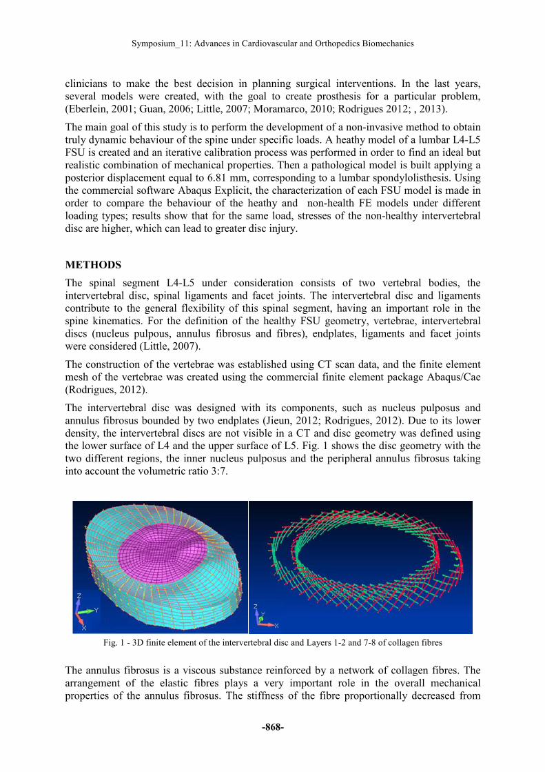
In order to model the intervertebral joints, facet joints were created in the contact area of the
two vertebrae. These facet joints were treated as a three-dimensional contact problem using
surface-to-surface soft contact with exponential-pressure-over closure option available in
ABAQUS. Finally the anterior longitudinal ligaments (ALL), the posterior longitudinal
ligaments (PLL), the supraspinous ligament (SSL), the interspinous ligaments (ISL), the
intertransverse ligaments (ITL), the ligamentum flavum (LF) and the capsular ligaments (CL)
were considered, and modelled with tension-only spring connector elements (truss elements
T3D2), similar to the definition of the collagen fibres. The complete model is presented in
Fig. 2a).
(a) (b)
Fig. 2 - 3D finite element: (a) healthy model; (b) pathologic model
In FE modelling of spinal motion segments generally it is considered that the segment is
supported rigidly along the inferior endplate of the lower vertebra, L5, and the loads are
applied on the superior endplate of the upper vertebra. The loads can be applied as static or
dynamic loads. In this study static loading situations were considered and all the loads were
applied in the superior surface of L4 through a reference node. The choice of mechanical
properties was performed by an iterative calibration process; considering a compression load
case a realistic combination of mechanical properties was obtained taking into account results
found in literature (Rodrigues, 2012). Elastic behaviour was considered for all FSU elements
(Rodrigues, 2012), except the nucleus pulposus and the viscous annulus that were considered
as hyper elastic materials. The vertebral bodies were taken as rigid bodies, thus there was no
difference between cortical and trabecular bone.
The pathological model, shown in Fig. 2b, was built applying a posterior displacement of 6.81
mm. The characterization of each model was performed using Abaqus Explicit: the two
models were subjected to pure moments and forces in the three anatomical planes. In order to
compare the mechanical behaviour of the two units, the maximum displacement and stress
fields were calculated.
Symposium_11: Advances in Cardiovascular and Orthopedics Biomechanics
-870-
RESULTS
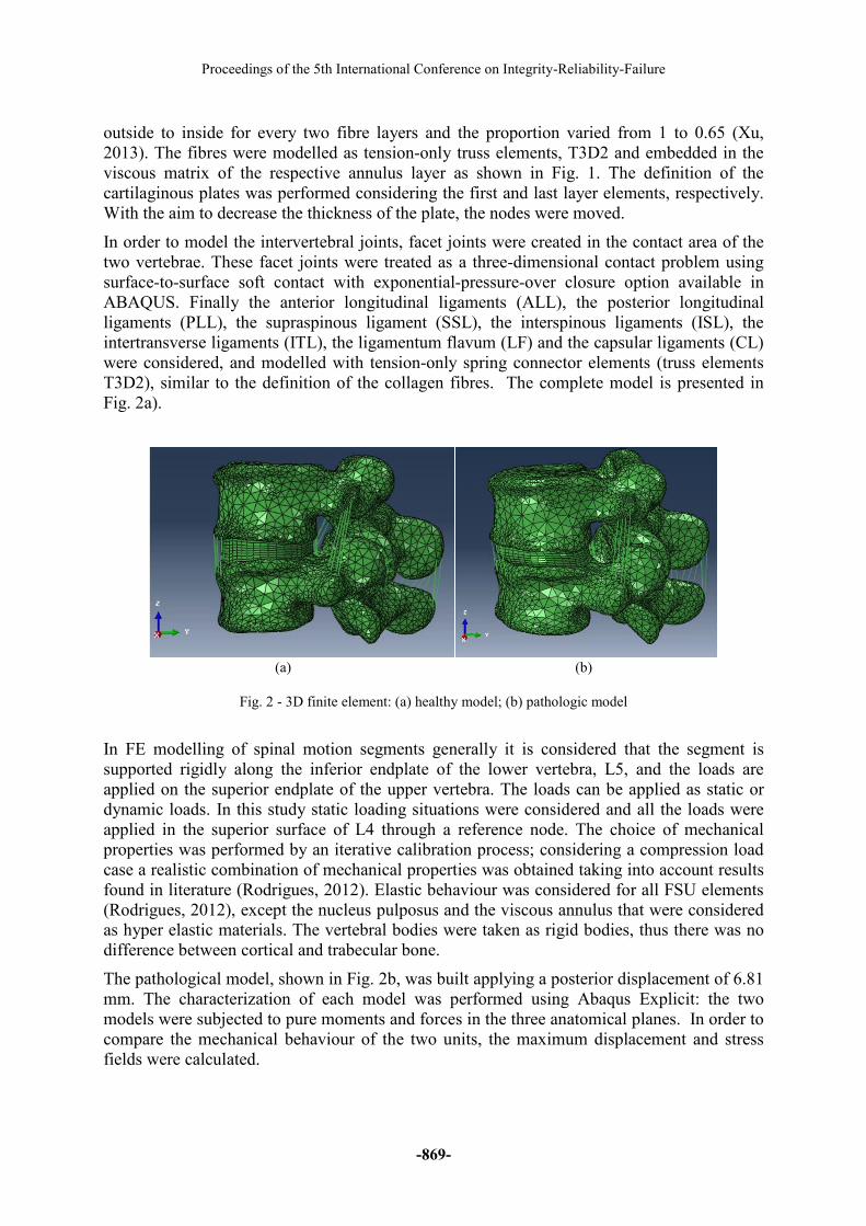
Two movements were analysed such as flexion and torsion. For each load case the axial
displacement field of the L4-L5 FSU, and the minimum principal stress distribution in the
intervertebral disc were analysed. Considering load cases flexion and torsion, moments of +20
Nm and +11.45 Nm were applied respectively.
(a) (b)
Fig. 3 - Axial displacement field (flexion load): (a) healthy model; (b) pathologic model
Figure 3 shows similar displacement fields for the healthy and non-healthy models,
considering flexion load; the healthy model presented a smaller axial displacement and in
both models the largest axial displacements are observed in vertebrae apophysis.
(a) (b)
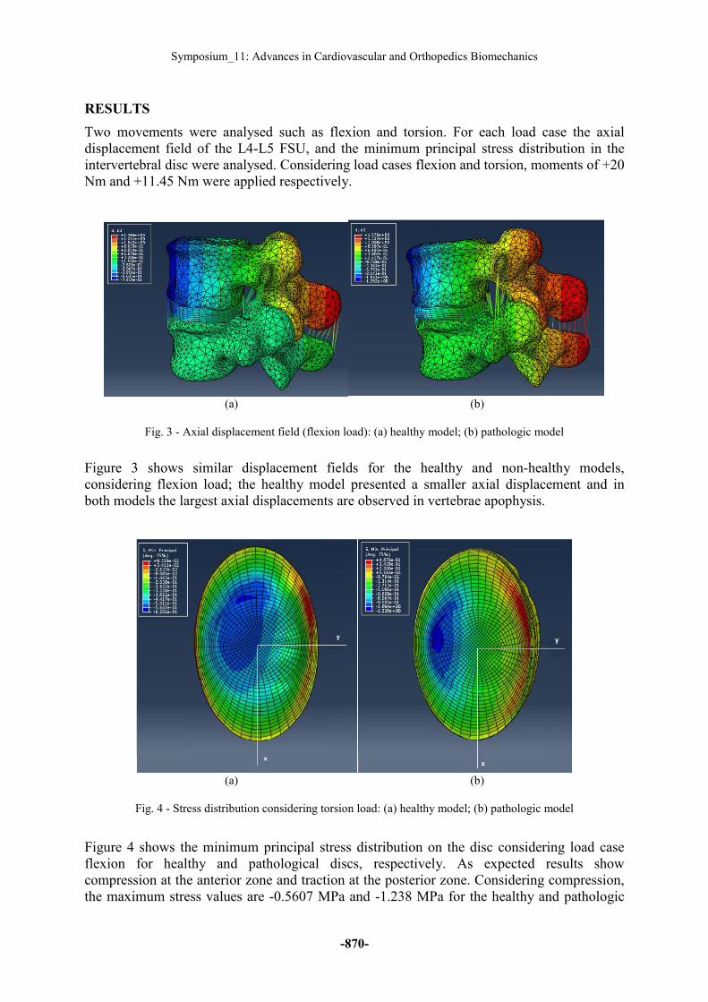
Fig. 4 - Stress distribution considering torsion load: (a) healthy model; (b) pathologic model
Figure 4 shows the minimum principal stress distribution on the disc considering load case
flexion for healthy and pathological discs, respectively. As expected results show
compression at the anterior zone and traction at the posterior zone. Considering compression,
the maximum stress values are -0.5607 MPa and -1.238 MPa for the healthy and pathologic
Proceedings of the 5th International Conference on Integrity-Reliability-Failure
-871-
discs respectively. Concluding, the pathological model presents higher stresses and is more
prone to deformations.
(a) (b)
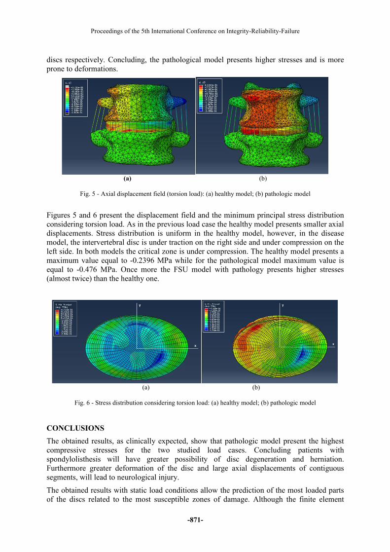
Fig. 5 - Axial displacement field (torsion load): (a) healthy model; (b) pathologic model
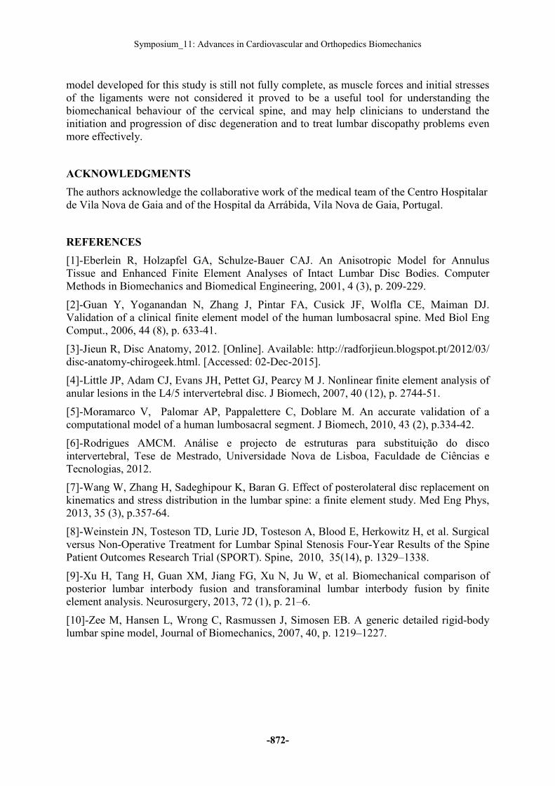
Figures 5 and 6 present the displacement field and the minimum principal stress distribution
considering torsion load. As in the previous load case the healthy model presents smaller axial
displacements. Stress distribution is uniform in the healthy model, however, in the disease
model, the intervertebral disc is under traction on the right side and under compression on the
left side. In both models the critical zone is under compression. The healthy model presents a
maximum value equal to -0.2396 MPa while for the pathological model maximum value is
equal to -0.476 MPa. Once more the FSU model with pathology presents higher stresses
(almost twice) than the healthy one.
(a) (b)
Fig. 6 - Stress distribution considering torsion load: (a) healthy model; (b) pathologic model
CONCLUSIONS
The obtained results, as clinically expected, show that pathologic model present the highest
compressive stresses for the two studied load cases. Concluding patients with
spondylolisthesis will have greater possibility of disc degeneration and herniation.
Furthermore greater deformation of the disc and large axial displacements of contiguous
segments, will lead to neurological injury.
The obtained results with static load conditions allow the prediction of the most loaded parts
of the discs related to the most susceptible zones of damage. Although the finite element
Symposium_11: Advances in Cardiovascular and Orthopedics Biomechanics
-872-
model developed for this study is still not fully complete, as muscle forces and initial stresses
of the ligaments were not considered it proved to be a useful tool for understanding the
biomechanical behaviour of the cervical spine, and may help clinicians to understand the
initiation and progression of disc degeneration and to treat lumbar discopathy problems even
more effectively.
ACKNOWLEDGMENTS
The authors acknowledge the collaborative work of the medical team of the Centro Hospitalar
de Vila Nova de Gaia and of the Hospital da Arrábida, Vila Nova de Gaia, Portugal.
REFERENCES
[1]-Eberlein R, Holzapfel GA, Schulze-Bauer CAJ. An Anisotropic Model for Annulus
Tissue and Enhanced Finite Element Analyses of Intact Lumbar Disc Bodies. Computer
Methods in Biomechanics and Biomedical Engineering, 2001, 4 (3), p. 209-229.
[2]-Guan Y, Yoganandan N, Zhang J, Pintar FA, Cusick JF, Wolfla CE, Maiman DJ.
Validation of a clinical finite element model of the human lumbosacral spine. Med Biol Eng
Comput., 2006, 44 (8), p. 633-41.
[3]-Jieun R, Disc Anatomy, 2012. [Online]. Available: http://radforjieun.blogspot.pt/2012/03/
disc-anatomy-chirogeek.html. [Accessed: 02-Dec-2015].
[4]-Little JP, Adam CJ, Evans JH, Pettet GJ, Pearcy M J. Nonlinear finite element analysis of
anular lesions in the L4/5 intervertebral disc. J Biomech, 2007, 40 (12), p. 2744-51.
[5]-Moramarco V, Palomar AP, Pappalettere C, Doblare M. An accurate validation of a
computational model of a human lumbosacral segment. J Biomech, 2010, 43 (2), p.334-42.
[6]-Rodrigues AMCM. Análise e projecto de estruturas para substituição do disco
intervertebral, Tese de Mestrado, Universidade Nova de Lisboa, Faculdade de Ciências e
Tecnologias, 2012.
[7]-Wang W, Zhang H, Sadeghipour K, Baran G. Effect of posterolateral disc replacement on
kinematics and stress distribution in the lumbar spine: a finite element study. Med Eng Phys,
2013, 35 (3), p.357-64.
[8]-Weinstein JN, Tosteson TD, Lurie JD, Tosteson A, Blood E, Herkowitz H, et al. Surgical
versus Non-Operative Treatment for Lumbar Spinal Stenosis Four-Year Results of the Spine
Patient Outcomes Research Trial (SPORT). Spine, 2010, 35(14), p. 1329–1338.
[9]-Xu H, Tang H, Guan XM, Jiang FG, Xu N, Ju W, et al. Biomechanical comparison of
posterior lumbar interbody fusion and transforaminal lumbar interbody fusion by finite
element analysis. Neurosurgery, 2013, 72 (1), p. 21–6.
[10]-Zee M, Hansen L, Wrong C, Rasmussen J, Simosen EB. A generic detailed rigid-body
lumbar spine model, Journal of Biomechanics, 2007, 40, p. 1219–1227.
Recommended