C
ERMET
AZ
IEN
D A C E R TIF
ICA
TA
UNI EN ISO 9001-085
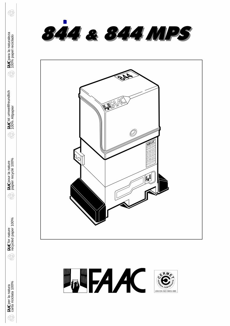
844 & 844 MPS
para
la n
atur
alez
a10
0% p
apel
rec
icla
dois
t um
wel
tfreu
ndlic
h10
0% A
ltpap
ier
pour
la n
atur
epa
pier
rec
yclé
100
%fo
r na
ture
recy
cled
pap
er 1
00%
cart
a ric
icla
ta 1
00%
per
la n
atur
a
844 & 844 MPS
Timbro del Rivenditore:/Distributor’s Stamp:/Timbre de l’Agent:/ Fachhändlerstempel:/Sello del Revendedor:
Le descrizioni e le illustrazioni del presente manuale non sono impegnative. La FAAC si riserva il diritto,lasciando inalterate le caratteristiche essenziali dell’apparecchiatura, di apportare in qualunquemomento e senza impegnarsi ad aggiornare la presente pubblicazione, le modifiche che essa ritieneconvenienti per miglioramenti tecnici o per qualsiasi altra esigenza di carattere costruttivo ocommerciale.
The descriptions and illustrations contained in the present manual are not binding. FAAC reserves theright, whilst leaving the main features of the equipments unaltered, to undertake any modificationsit holds necessary for either technical or commercial reasons, at any time and without revising thepresent publication.
Les descriptions et les illustrations du présent manuel sont fournies à titre indicatif. FAAC se réserve ledroit d’apporter à tout moment les modifications qu’elle jugera utiles sur ce produit tout en conservantles caractéristiques essentielles, sans devoir pour autant mettre à jour cette publication.
Die Beschreibungen und Abbildungen in vorliegendem Handbuch sind unverbindlich. FAAC behältsich das Recht vor, ohne die wesentlichen Eigenschaften dieses Gerätes zu verändern und ohneVerbindlichkeiten in Bezug auf die Neufassung der vorliegenden Anleitungen, technisch bzw.konstruktiv/kommerziell bedingte Verbesserungen vorzunehmen.
Las descripciones y las ilustraciones de este manual no comportan compromiso alguno. FAAC sereserva el derecho, dejando inmutadas las características esenciales de los aparatos, de aportar, encualquier momento y sin comprometerse a poner al día la presente publicación, todas lasmodificaciones que considere oportunas para el perfeccionamiento técnico o para cualquier otrotipo de exigencia de carácter constructivo o comercial.
FAAC S.p.A.Via Benini, 140069 Zola Predosa (BO) - ITALIATel.: 051/6172411 - Tlx.: 521087Fax: 051/758518
FAAC per la natura• La presente istruzione è realizzata al 100% in carta riciclata.• Non disperdete nell'ambiente gli imballaggi dei componenti dell'automazione bensì selezionate
i vari materiali (es. cartone, polistirolo) secondo prescrizioni locali per lo smaltimento rifiuti e lenorme vigenti.
FAAC for the environment• The present manual is produced in 100% recycled paper• Respect the environment. Dispose of each type of product packaging material (card, polystyrene)
in accordance with the provisions for waste disposal as specified in the country of installation.
FAAC der Umwelt zuliebe• Vorliegende Anleitungen sind auf 100% Altpapier gedruckt.• Verpackungsstoffe der Antriebskomponenten (z.B. Pappe, Styropor) nach den einschlägigen
Normen der Abfallwirtschaft sortenrein sammeln.FAAC écologique• La présente notice a été réalisée 100% avec du papier recyclé.• Ne pas jeter dans la nature les emballages des composants de l’automatisme, mais sélectionner
les différents matériaux (ex.: carton, polystyrène) selon la législation locale pour l’élimination desdéchets et les normes en vigueur.
FAAC por la naturaleza.• El presente manual de instrucciones se ha realizado, al 100%, en papel reciclado.• Los materiales utilizados para el embalaje de las distintas partes del sistema automático (cartón,
poliestireno) no deben tirarse al medio ambiente, sino seleccionarse conforme a las prescripcioneslocales y las normas vigentes para el desecho de residuos sólidos.
7322
42 -
Re
v.A
para
la n
atur
alez
a10
0% p
apel
rec
icla
dois
t um
wel
tfreu
ndlic
h10
0% A
ltpap
ier
pour
la n
atur
epa
pier
rec
yclé
100
%fo
r na
ture
recy
cled
pap
er 1
00%
cart
a ric
icla
ta 1
00%
per
la n
atur
a
12
ENGLISH ENGLISH
EC MACHINE DIRECTIVE COMPLIANCE DECLARATION
(DIRECTIVE 89/392 EEC, APPENDIX II, PART B)
Manufacturer: FAAC S.p.A.
Address: Via Benini, 140069 - Zola PredosaBOLOGNA - ITALY
Hereby declares that: the 844 automation system
•is intended to be incorporated into machinery, or to be assembled withother machinery to constitute machinery in compliance with the requirementsof Directive 89/392 EEC, and subsequent amendments 91/368 EEC, 93/44EEC and 93/68 EEC;
•complies with the essential safety requirements in the following EEC Directives:
73/23 EEC and subsequent amendment 93/68 EEC.89/336 EEC and subsequent amendments 92/31 EEC and 93/68 EEC.
and furthermore declares that unit must not be put into service until themachinery into which it is incorporated or of which it is a component hasbeen identified and declared to be in conformity with the provisions ofDirective 89/392 EEC and subsequent amendments enacted by the nationalimplementing legislation.
Bologna, 1 January 1997
ManagingDirector
A. Bassi

13
ENGLISHENGLISH
IMPORTANT NOTICE FOR THE INSTALLER
GENERAL SAFETY INSTRUCTIONS1) WARNING! For reasons of safety, all the instructions in this manual must be observed scrupulously. Improper
installation or misuse of the product may result in serious injury.
2) Read the instructions carefully before installing the product.
3) Packaging material (plastic, polystyrene etc.) is a potential hazard and must be kept out of reach of children.
4) Keep these instructions for future reference.
5) This product has been designed and manufactured only for the use stated in this manual. Any use other than thatexpressly indicated may result in damage to the product and/or risk of injury.
6) FAAC S.p.A. shall not be liable for any damage or injury caused by improper use of the automation or by any useother than that for which it is intended.
7) Do not install this device in explosive atmospheres: the presence of flammable gas or fumes is a serious hazard.
8) Mechanical structural elements must comply with UNI8612, CEN pr EN 12604 and CEN pr EN 12605 standards.For countries outside the EC, mechanical structural must comply with the above standards in addition to anynational safety standards, in order to obtain a reasonable degree of safety.
9) FAAC cannot be held responsible for failure to observe technical standards in the construction of the gates on whichthe automation is installed, or for any deformation of the gates which may occur during use.
10) Installation must comply with UNI8612, CEN pr EN 12453 and CEN pr EN 12635.The degree of safety of the automation must be C+D.
11) Before carrying out any operations on the system, disconnect the electrical power supply.
12) Install a multi-pole switch on the supply line to the automation with a contact opening distance of 3 mm or more.We recommend the use of a 6A thermal magnetic circuit breaker with multi-pole switching.
13) Ensure that a residual current device with a trip threshold of 0.03A is installed upstream of the automation system.
14) Check that the earthing system is installed correctly and is efficient. Connect the metal parts of the gate and theyellow/green wire of the operator to the earthing system.
15) The automation is fitted with an anti-crushing safety system consisting of a torque control device which, in all cases,must be used in conjunction with other safety devices.
16) The safety devices (e.g. photocells, safety edges, etc.) protect areas where there is a mechanical movementhazard, e.g. crushing, entrapment and cutting.
17) Each installation must be fitted with at least one flashing light (e.g. FAAC LAMP, MINILAMP etc.) and a warning signsuitably fixed to the gate, in addition to the safety devices as per point 16 above.
18) FAAC cannot be held responsible for the safe and correct operation of the automation in the event that parts otherthan FAAC original parts are used.
19) Use only FAAC original spare parts for maintenance operations.
20) Do not carry out any modifications to automation components.
21) The installer must supply all information regarding manual operation of the system in the event of an emergencyand provide the end-user with the "End-user Guide" supplied with the product.
22) Do not allow any persons, especially children, to stand in the vicinity of the automation when in operation.
23) Keep the remote radio controls and any other control devices out of the reach of children to prevent accidentaloperation of the automation.
24) The end-user must not attempt to repair or adjust the automation. These operations must be carried out exclusivelyby qualified personnel.
25) Any operations not explicitly described in these instructions are not permitted.
14
ENGLISH ENGLISH
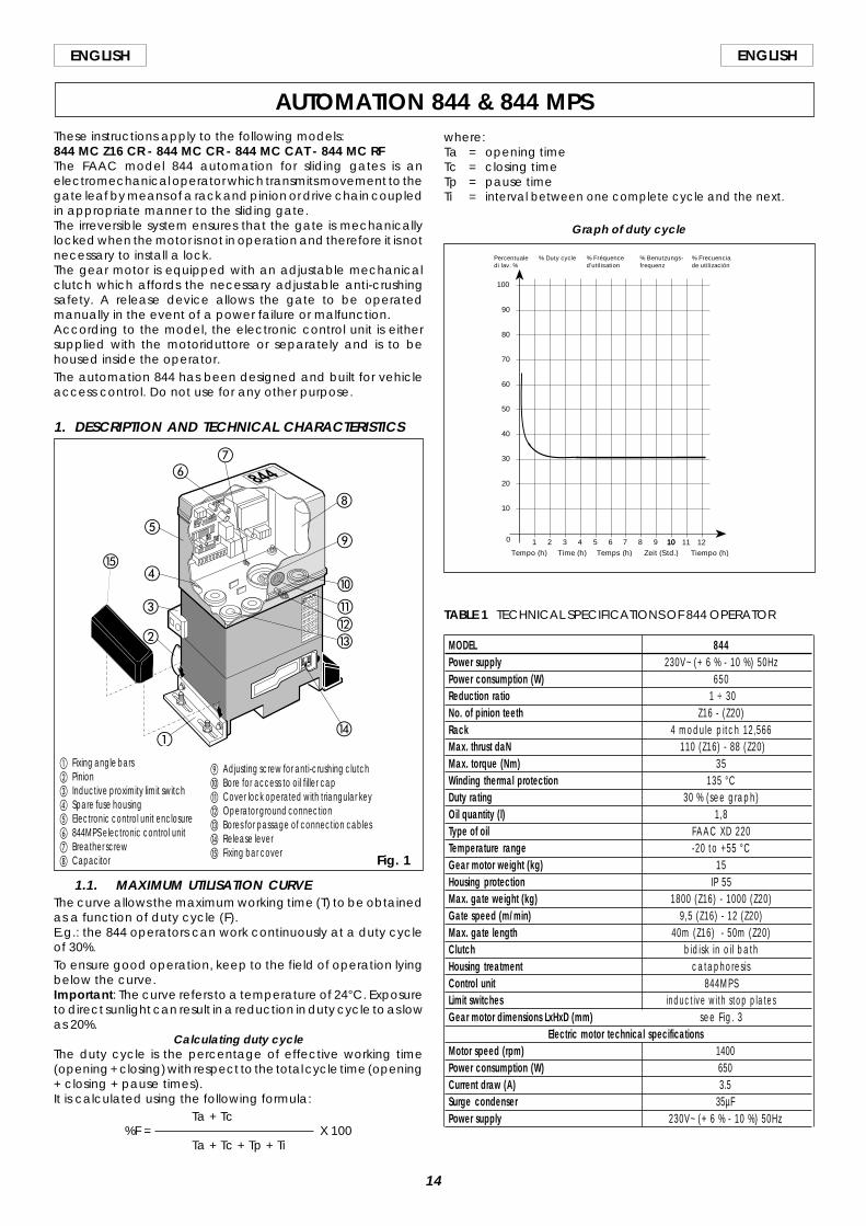
These instructions apply to the following models:844 MC Z16 CR - 844 MC CR - 844 MC CAT - 844 MC RFThe FAAC model 844 automation for sliding gates is anelectromechanical operator which transmits movement to thegate leaf by means of a rack and pinion or drive chain coupledin appropriate manner to the sliding gate.The irreversible system ensures that the gate is mechanicallylocked when the motor is not in operation and therefore it is notnecessary to install a lock.The gear motor is equipped with an adjustable mechanicalclutch which affords the necessary adjustable anti-crushingsafety. A release device allows the gate to be operatedmanually in the event of a power failure or malfunction.According to the model, the electronic control unit is eithersupplied with the motoriduttore or separately and is to behoused inside the operator.The automation 844 has been designed and built for vehicleaccess control. Do not use for any other purpose.
1. DESCRIPTION AND TECHNICAL CHARACTERISTICS
AUTOMATION 844 & 844 MPS
MODEL 844Power supply 230V~ (+ 6 % - 10 %) 50HzPower consumption (W) 650Reduction ratio 1 ÷ 30No. of pinion teeth Z16 - (Z20)Rack 4 module pitch 12,566Max. thrust daN 110 (Z16) - 88 (Z20)Max. torque (Nm) 35Winding thermal protection 135 °CDuty rating 30 % (see graph)Oil quantity (l) 1,8Type of oil FAAC XD 220Temperature range -20 to +55 °CGear motor weight (kg) 15Housing protection IP 55Max. gate weight (kg) 1800 (Z16) - 1000 (Z20)Gate speed (m/min) 9,5 (Z16) - 12 (Z20)Max. gate length 40m (Z16) - 50m (Z20)Clutch bidisk in oi l bathHousing treatment cataphoresisControl unit 844MPSLimit switches inductive with stop platesGear motor dimensions LxHxD (mm) see Fig. 3
Electric motor technical specificationsMotor speed (rpm) 1400Power consumption (W) 650Current draw (A) 3.5Surge condenser 35µFPower supply 230V~ (+ 6 % - 10 %) 50Hz
TABLE 1 TECHNICAL SPECIFICATIONS OF 844 OPERATOR
1.1. MAXIMUM UTILISATION CURVEThe curve allows the maximum working time (T) to be obtainedas a function of duty cycle (F).E.g.: the 844 operators can work continuously at a duty cycleof 30%.To ensure good operation, keep to the field of operation lyingbelow the curve.Important: The curve refers to a temperature of 24°C. Exposureto direct sunlight can result in a reduction in duty cycle to as lowas 20%.
Calculating duty cycleThe duty cycle is the percentage of effective working time(opening + closing) with respect to the total cycle time (opening+ closing + pause times).It is calculated using the following formula:
Ta + Tc%F = X 100
Ta + Tc + Tp + Ti
where:Ta = opening timeTc = closing timeTp = pause timeTi = interval between one complete cycle and the next.
Graph of duty cycle
Fig. 1
a Fixing angle barsb Pinionc Inductive proximity limit switchd Spare fuse housinge Electronic control unit enclosuref 844MPS electronic control unitg Breather screwh Capacitor
i Adjusting screw for anti-crushing clutchj Bore for access to oil filler capk Cover lock operated with triangular keyl Operator ground connectionm Bores for passage of connection cablesn Release levero Fixing bar cover
b
a
c
d
e
fg
h
i
j
klm
n
o
10
20
30
40
50
60
70
80
90
100
0 1 2 3 4 5 6 7 8 9 10 10 11 12
Percentuale di lav. %
Tiempo (h)
% Duty cycle % Fréquenced'utilisation
% Benutzungs- frequenz
% Frecuencia de utilización
Zeit (Std.)Temps (h)Time (h)Tempo (h)
15
ENGLISHENGLISH
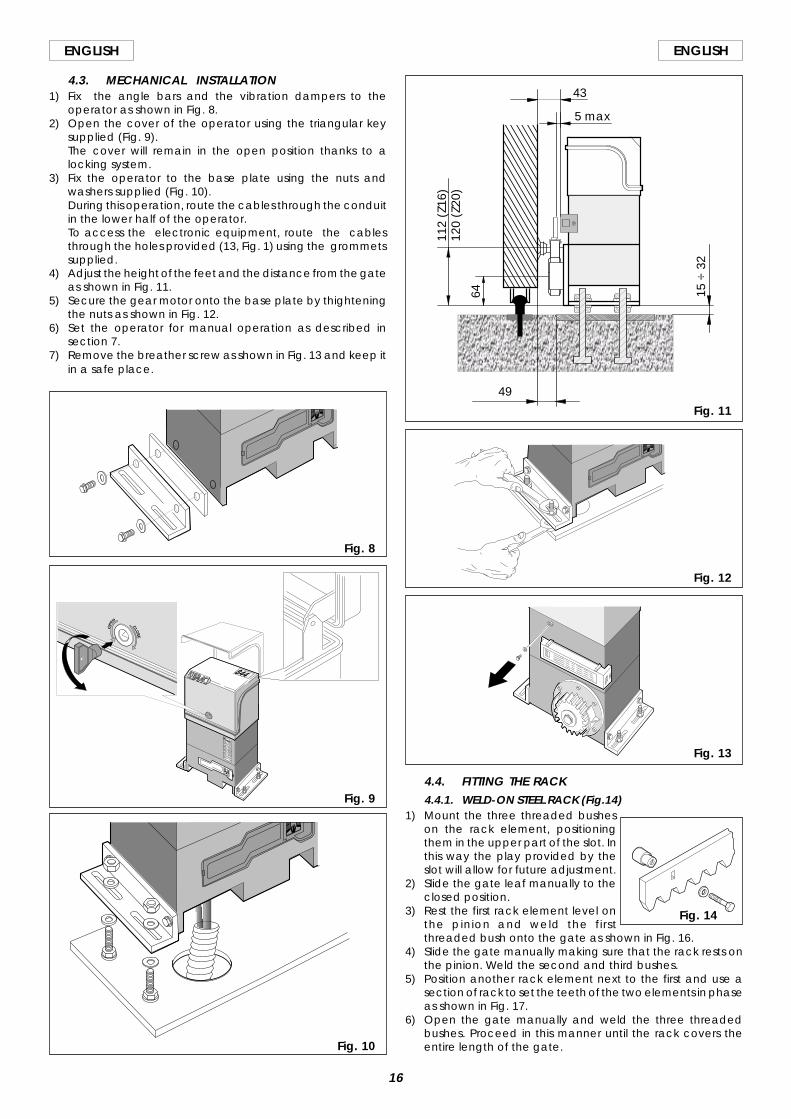
a 844 operator with844 MPS control unit
b Photocellsc Key switchd Flashing lighte Radio receiver Fig. 3
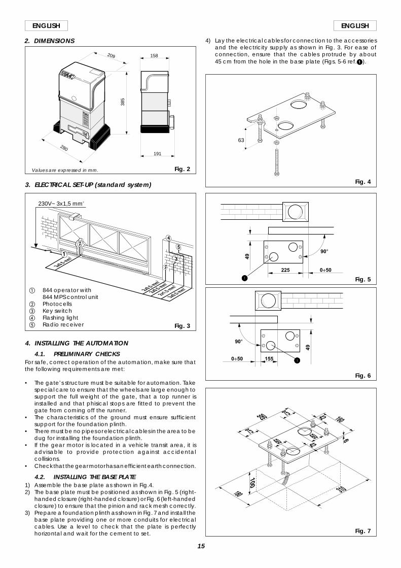
2. DIMENSIONS
Fig. 2Values are expressed in mm.
3. ELECTRICAL SET-UP (standard system)
4. INSTALLING THE AUTOMATION
4.1. PRELIMINARY CHECKSFor safe, correct operation of the automation, make sure thatthe following requirements are met:
• The gate’s structure must be suitable for automation. Takespecial care to ensure that the wheels are large enough tosupport the full weight of the gate, that a top runner isinstalled and that phisical stops are fitted to prevent thegate from coming off the runner.
• The characteristics of the ground must ensure sufficientsupport for the foundation plinth.
• There must be no pipes or electrical cables in the area to bedug for installing the foundation plinth.
• If the gear motor is located in a vehicle transit area, it isadvisable to provide protection against accidentalcollisions.
• Check that the gear motor has an efficient earth connection.
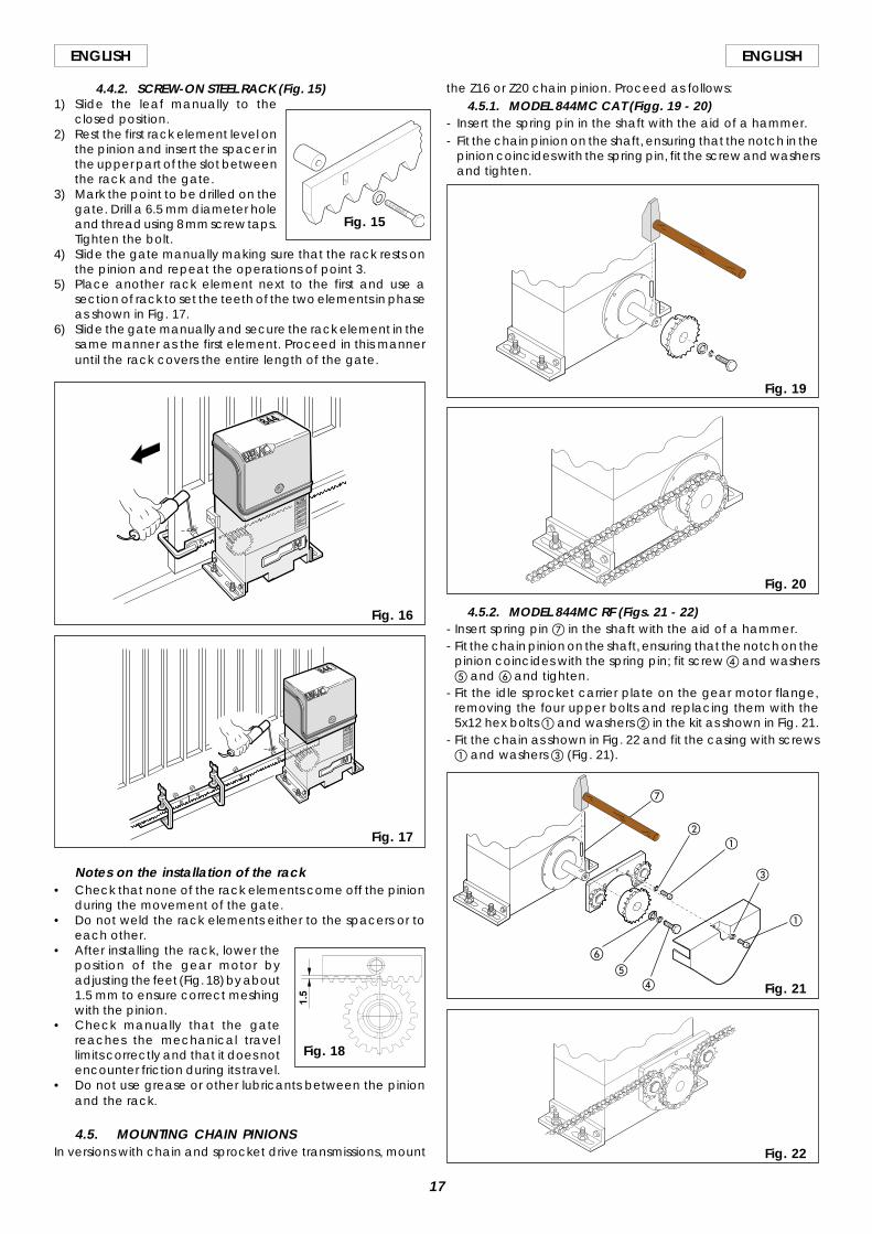
4.2. INSTALLING THE BASE PLATE1) Assemble the base plate as shown in Fig.4.2) The base plate must be positioned as shown in Fig. 5 (right-
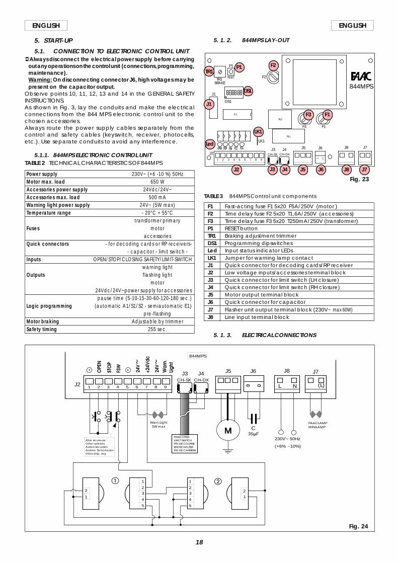
handed closure (right-handed closure) or Fig. 6 (left-handedclosure) to ensure that the pinion and rack mesh correctly.
3) Prepare a foundation plinth as shown in Fig. 7 and install thebase plate providing one or more conduits for electricalcables. Use a level to check that the plate is perfectlyhorizontal and wait for the cement to set.
4) Lay the electrical cables for connection to the accessoriesand the electricity supply as shown in Fig. 3. For ease ofconnection, ensure that the cables protrude by about45 cm from the hole in the base plate (Figs. 5-6 ref.1).
Fig. 7
385
280191
158209
230V~ 3x1,5 mm2
Fig. 4
63
Fig. 5
Fig. 6
225
90°49
0÷50
49
0÷50 155
90°
11111
11111
16
ENGLISH ENGLISH
4.3. MECHANICAL INSTALLATION1) Fix the angle bars and the vibration dampers to the
operator as shown in Fig. 8.2) Open the cover of the operator using the triangular key
supplied (Fig. 9).The cover will remain in the open position thanks to alocking system.
3) Fix the operator to the base plate using the nuts andwashers supplied (Fig. 10).During this operation, route the cables through the conduitin the lower half of the operator.To access the electronic equipment, route the cablesthrough the holes provided (13, Fig. 1) using the grommetssupplied.
4) Adjust the height of the feet and the distance from the gateas shown in Fig. 11.
5) Secure the gear motor onto the base plate by thighteningthe nuts as shown in Fig. 12.
6) Set the operator for manual operation as described insection 7.
7) Remove the breather screw as shown in Fig. 13 and keep itin a safe place.
Fig. 11
Fig. 12
Fig. 8
4.4. FITTING THE RACK4.4.1. WELD-ON STEEL RACK (Fig.14)
1) Mount the three threaded busheson the rack element, positioningthem in the upper part of the slot. Inthis way the play provided by theslot will allow for future adjustment.
2) Slide the gate leaf manually to theclosed position.
3) Rest the first rack element level onthe pinion and weld the firstthreaded bush onto the gate as shown in Fig. 16.
4) Slide the gate manually making sure that the rack rests onthe pinion. Weld the second and third bushes.
5) Position another rack element next to the first and use asection of rack to set the teeth of the two elements in phaseas shown in Fig. 17.
6) Open the gate manually and weld the three threadedbushes. Proceed in this manner until the rack covers theentire length of the gate.
Fig. 13
Fig. 9
Fig. 10
5 max
43
112
(Z16
)12
0 (Z
20)
64
49
15 ÷
32
Fig. 14
17
ENGLISHENGLISH
4.4.2. SCREW-ON STEEL RACK (Fig. 15)1) Slide the leaf manually to the
closed position.2) Rest the first rack element level on
the pinion and insert the spacer inthe upper part of the slot betweenthe rack and the gate.
3) Mark the point to be drilled on thegate. Drill a 6.5 mm diameter holeand thread using 8 mm screw taps.Tighten the bolt.
4) Slide the gate manually making sure that the rack rests onthe pinion and repeat the operations of point 3.
5) Place another rack element next to the first and use asection of rack to set the teeth of the two elements in phaseas shown in Fig. 17.
6) Slide the gate manually and secure the rack element in thesame manner as the first element. Proceed in this manneruntil the rack covers the entire length of the gate.
Fig. 16
Fig. 17
Notes on the installation of the rack• Check that none of the rack elements come off the pinion
during the movement of the gate.• Do not weld the rack elements either to the spacers or to
each other.• After installing the rack, lower the
position of the gear motor byadjusting the feet (Fig. 18) by about1.5 mm to ensure correct meshingwith the pinion.
• Check manually that the gatereaches the mechanical travellimits correctly and that it does notencounter friction during its travel.
• Do not use grease or other lubricants between the pinionand the rack.
4.5. MOUNTING CHAIN PINIONSIn versions with chain and sprocket drive transmissions, mount
the Z16 or Z20 chain pinion. Proceed as follows:4.5.1. MODEL 844MC CAT (Figg. 19 - 20)
- Insert the spring pin in the shaft with the aid of a hammer.- Fit the chain pinion on the shaft, ensuring that the notch in the
pinion coincides with the spring pin, fit the screw and washersand tighten.
4.5.2. MODEL 844MC RF (Figs. 21 - 22)- Insert spring pin g in the shaft with the aid of a hammer.- Fit the chain pinion on the shaft, ensuring that the notch on the
pinion coincides with the spring pin; fit screw d and washerse and f and tighten.
- Fit the idle sprocket carrier plate on the gear motor flange,removing the four upper bolts and replacing them with the5x12 hex bolts a and washers b in the kit as shown in Fig. 21.
- Fit the chain as shown in Fig. 22 and fit the casing with screwsa and washers c (Fig. 21).
Fig. 20
Fig. 19
Fig. 22
Fig. 15
Fig. 18
1.5 Fig. 21
a
ab
c
de
f
g
18
ENGLISH ENGLISH
5. START-UP
5.1. CONNECTION TO ELECTRONIC CONTROL UNITÜAlways disconnect the electrical power supply before carrying
out any operations on the control unit (connections, programming,maintenance).Warning: On disconnecting connector J6, high voltages may bepresent on the capacitor output.
Observe points 10, 11, 12, 13 and 14 in the GENERAL SAFETYINSTRUCTIONS.As shown in Fig. 3, lay the conduits and make the electricalconnections from the 844 MPS electronic control unit to thechosen accessories.Always route the power supply cables separately from thecontrol and safety cables (keyswitch, receiver, photocells,etc.). Use separate conduits to avoid any interference.
5.1.1. 844MPS ELECTRONIC CONTROL UNITTABLE 2 TECHNICAL CHARACTERISTICS OF 844MPS
Power supply 230V~ (+6 -10 %) 50HzMotor max. load 650 WAccessories power supply 24Vdc/24V~Accessories max. load 500 mAWarning light power supply 24V~ (5W max)Temperature range - 20°C + 55°C
transformer primaryFuses motor
accessoriesQuick connectors - for decoding cards or RP receivers-
- capacitor - l imit switch -Inputs OPEN/STOP/CLOSING SAFETY/LIMIT-SWITCH
warning lightOutputs flashing light
motor24Vdc/24V~power supply for accessoriespause time (5-10-15-30-60-120-180 sec.)
Logic programming (automatic A1/S1/S2 - semiautomatic E1)pre-flashing
Motor braking Adjustable by trimmerSafety timing 255 sec.
5. 1. 2. 844MPS LAY-OUT
TABLE 3 844MPS Control unit components
F1 Fast-acting fuse F1 5x20 F5A/250V (motor )F2 Time delay fuse F2 5x20 T1,6A/250V (accessories)F3 Time delay fuse F3 5x20 T250mA/250V (transformer)P1 RESET buttonTR1 Braking adjustment trimmerDS1 Programming dipswitchesLed Input status indicator LEDsLK1 Jumper for warning lamp contactJ1 Quick connector for decoding cards/RP receiverJ2 Low voltage inputs/accessories terminal blockJ3 Quick connector for limit switch (LH closure)J4 Quick connector for limit switch (RH closure)J5 Motor output terminal blockJ6 Quick connector for capacitorJ7 Flasher unit output terminal block (230V~ max 60W)J8 Line input terminal block
5. 1. 3. ELECTRICAL CONNECTIONS
Fig. 24
J4J3
J2CH-DXCH-SX
1 2 3 4 5 6 7 8 9
M
12
1
23
4
5
J5 J6 J8 J7
230V~ 50Hz
(+6% -10%)
C35µF
FAACLAMPMINILAMP
Warn.Light 5W max
844MPS
L N (L)
FINECORSALIMIT SWITCHFIN DE COURSEENDSCHALTERFIN DE CARRERA
1
23
4
5
1
2
Altre sicurezzeOther safetiesAutres sécuritésAndere SicherheitenOtros disp. seg.
a b
Fig. 23
P1
RESETTR1BRAKE
F2
F1F3
J7J8J6J5J4J3J2 CH-DXCH-SX
J1
DS1
RL1
RL2
IC1
LK1
1 2 3 4 5 6 7 8 9
844MPS
F1F3
P1TR1
J1
Led
LK1
J2 J5 J6 J8 J7J3 J4
DS1
F2
19
ENGLISHENGLISH
5.2. DESCRIPTION5.2.1. CONNECTOR J1
The connector J1 is used for the quick connection ofMINIDEC,DECODER, RP RECEIVER boards (Figs. 25,26,27).Accessory boards are to be inserted with their componentsides facing the inside of the 844MPS electronic control unit.Always disconnect the power supply before inserting orremoving accessory boards.
5.2.2. TERMINAL BLOCK J2 (low voltage)1& 5 = Common/Negative of accessory power supply (-)2 = OPEN control device (N.O.)
Any control device (pushbutton, detector,..) which,on closing the contact, relays an open and/or closeimpulse to the gate.To instal l more than one Open control device,connect the N.O. contacts in parallel.
3 = STOP control device (N.C.)Any control device (e.g. pushbutton) which, onopening a contact, stops the movement of the gate.To install more than one Stop control device, connectthe N.C. contacts in series.ÜIf no Stop control devices are to be connected,place a jumper across the input and the commonterminal (terminal 1 or 5).
4 = FSW closure safety device (N.C.)Any control device (photocel l s , safety edges,magnet ic loops) w i th an N.C. contact w hichinterrupts the movement of the gate when anobstacle is detected within the protected area.The task of the closure safety device is to safeguardthe area occupied by the gate during the closingmovement.The intervention of safety devices dur ing gateclosure causes the direction of gate movement tobe reversed. These devices do not intervene duringgate opening movements. If a closure safety deviceis tripped when the gate is open or during a pausetime, they will prevent gate closure.To install more than one safety device, connect theN.C. contacts in series.Ü If no closure safety devices are to be installed,place a jumper across this input and the commmonterminal (terminal 1or5).
6&8 = 24V~ accessories power supplyThe maximum load of the accessories is 500mA.To calculate power draw, refer to the instructions forthe individual accessories.ÜIf the jumper LK1 is broken, the 24V~ accessoriespower supply is no longer available (Fig.28).
7 = 24Vdc accessories power supply positive (+)The maximum load of the accessories is 500mA.To calculate power draw, refer to the instructions forthe individual accessories.
9 = Warning Light outputFor information regarding operation of the warninglight, refer to the section on dipswitch programming.
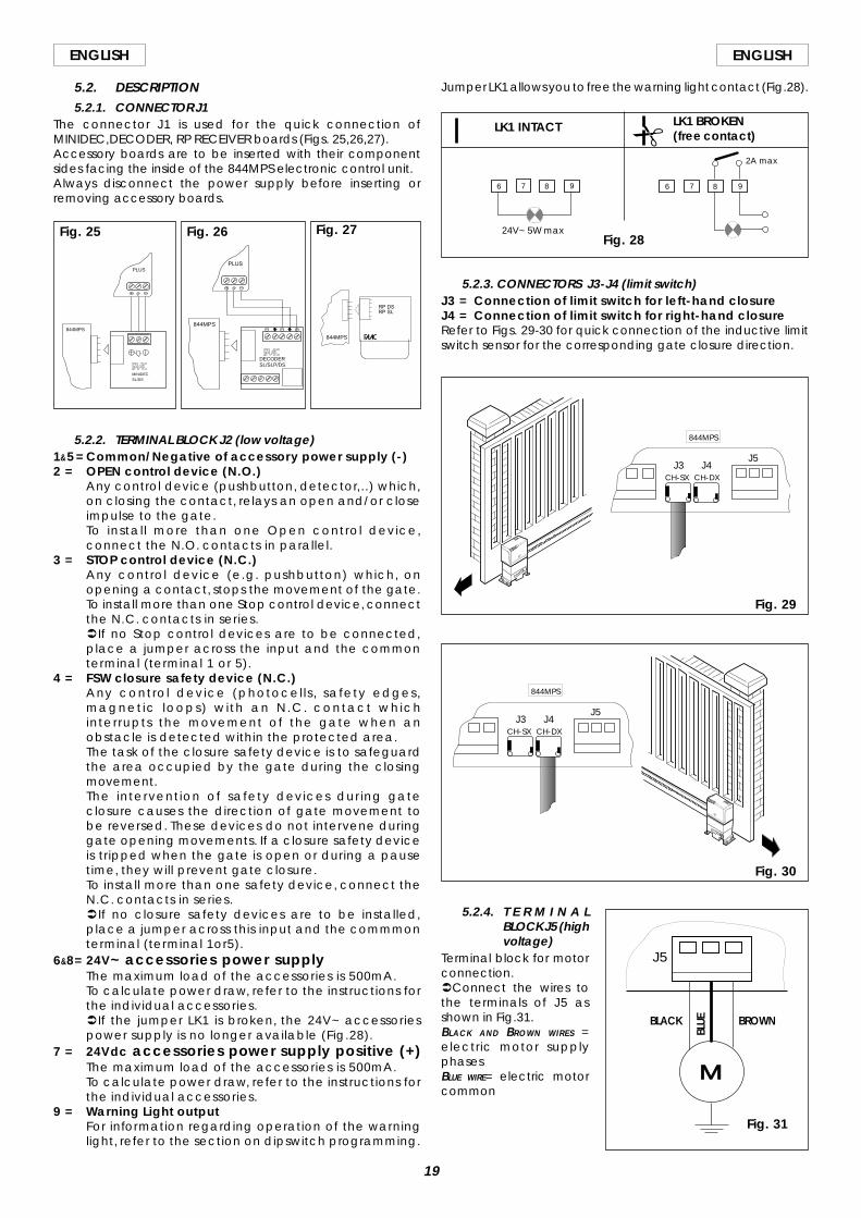
Jumper LK1 allows you to free the warning light contact (Fig.28).
5.2.3. CONNECTORS J3-J4 (limit switch)J3 = Connection of limit switch for left-hand closureJ4 = Connection of limit switch for right-hand closureRefer to Figs. 29-30 for quick connection of the inductive limitswitch sensor for the corresponding gate closure direction.
LK1 INTACT LK1 BROKEN(free contact)
Fig. 28
)
5.2.4. T E R M I N A LBLOCK J5 (highvoltage)
Terminal block for motorconnection.ÜConnect the wires tothe terminals of J5 asshown in Fig.31.BLACK AND BROWN WIRES =electric motor supplyphasesBLUE WIRE= electric motorcommon
Fig. 27Fig. 26Fig. 25
MINIDECSL/DS
PLUS
844MPS
DECODERSL/SLP/DS
844MPS
844MPS
6 987 6 987
24V~ 5W max
2A max
Fig. 29
J4J3CH-DXCH-SX
844MPS
J5
Fig. 30
J4J3CH-DXCH-SX
844MPS
J5
BROWNBLACK
BLUE
Fig. 31
M
J5
20
ENGLISH ENGLISH
Fig. 32
5.2.8. INDICATOR LEDS5 LEDs on the board indicate the status of the terminal imputs:LED ON = contact closedLED OFF = contact open
Fig. 33
To program the operation of the automation, set the dipswitchesas shown in the diagram above.Ü Press the RESET button after all programming operations.Operating logicsThere are four operating logics available:A1 = Automatic S1 = SafetyS2 = Safety Plus E = Semi-automaticOperation of the different logics is described in tables 5-6-7-8.Pause timeThe pause time is amount of time the gate remains open beforeit re-closes when an automatic control logic is selected.Pause times include the pre-flashing time, if selected.Warning light operationAllows you to vary the flashing rate of the warning light duringgate closure.Pre-flashingIt is possible to select 5 seconds pre-flashing of the flashing lightbefore any gate movement. This serves to warn any persons inthe vicinity that the gate is about to start moving.
(1) With the pre-flashing selected, movement starts after 5 seconds.(2) If the impulse is sent during pre-flashing, the timer is reset to zero.
TABLE 4 MEANING OF STATUS INDICATOR LEDS
LED ON OFF
OPEN Command active Command not activeSTOP Command not active Command activeFSW Safeties disengaged Safeties engagedFCC Closing limit disengaged Closing limit engagedFCA Opening limit disengaged Opening limit engaged
5.3. DIPSWITCH SETTINGS
5.2.5. CONNECTOR J6 (high voltage)Connector for quick connection of the capacitor.
5.2.6. TERMINAL BLOCK J7 (high voltage)230V~ terminal block for connection of the flashing light (max60W).
5.2.7. TERMINAL BLOCK J8 (high voltage)Terminal block for connection of the 230V~ 50Hz power supply(L=Line N=Neutral)Connect the earth wire to the operator as shown in Fig.32.
IMPULSESLOGIC A1
SAFETYno effect
freezes pause untildisengagementinverts motion
no effectno effect
STOPno effect
stops counting
stopsstops
no effect
GATE STATUSCLOSED
OPEN
CLOSINGOPENINGSTOPPED
OPENopens and recloses after
pause time (1)recloses after 5 s (2)
inverts motionno effect
recloses (1)
TABLE 5 LOGIC A1 (AUTOMATIC)
LOGIC S1 IMPULSESGATE STATUS
CLOSED
OPEN
CLOSINGOPENINGSTOPPED
OPENopens and recloses after
pause time (1)recloses immediately
(1 and 2)inverts motioninverts motion
recloses (1)
STOPno effect
stops counting
stopsstops
no effect
SAFETYno effect
recloses after 5 sfrom disengagement
inverts motionno effectno effect
TABLE 6 LOGIC S1 (SAFETY)
LOGIC S2 IMPULSESSTOP
no effect
stops counting
stops
stopsno effect
GATE STATUSCLOSED
OPEN
CLOSING
OPENINGSTOPPED
OPENopens and recloses after
pause time (1)recloses immediately
(1 and 2)inverts motion
inverts motionrecloses (1)
SAFETYno effect
freezes pause untildisengagement
stops and inverts motionwhen disengaged (1)
no effectno effect
TABLE 7 LOGIC S2 (SAFETY PLUS)
TABLE 8 LOGIC E1 (SEMI-AUTOMATIC)
SAFETYno effectno effect
inverts motionno effectno effect
GATE STATUSCLOSED
OPENCLOSINGOPENINGSTOPPED
OPENopens (1)
recloses (1)inverts motion
stopsrecloses (reopens when safety
devices are engaged) (1)
STOPno effectno effect
stopsstops
no effect
IMPULSESLOGIC E1
J2
LK1
1 2 3 4 5 6 7 8 9
1 2 3 4 5 6
Warning light operationGate status
SW5 Closed Opening/Open Closing
ON
OFF
Steady lightFlashing
OFF Steady light
Pre-flashing SW6
YES ON
NO OFF
Logic SW1 SW2
E1 ON ON
A1 ON OFF
S2 OFF ON
S1 OFF OFF
Pause time (sec) Logic
A1 - S2 S1 SW3 SW4
5 15 ON ON
10 30 OFF ON
30 60 ON OFF
120 180 OFF OFFON
OFF
21
ENGLISHENGLISH
5.4. FAULT CONDITIONSThe following conditions effect normal operation of theautomation:a microprocessor errorb intervention of the electronic safety timer (interruption of
operation after continuous working time exceeds 255seconds).
c disconnection of the limit switch cable connector• Conditions a and b have the sole effect of causing the
automation to stop.• Condition c causes an alarm condition inhibiting all
operation:normal operation is only resumed after the cause of the alarmhas been eliminated and the RESET button has been pressed(or the power supply has been momentarily interrupted).To signal this condition, the warning light must be connected:an alarm condition is signalled by rapid flashing (0.25 sec) ofthe warning light.
5.5. POSITIONING THE TRAVEL STOP PLATEThe 844 operator is fitted with an inductive proximity limit switch(Fig.1 - ref.3). When the latter detects the passage of a platefastened to the top of the rack, it stops the movement of the gate.To position the two travel stop plates correctly, proceed asfollows:1) Connect the limit switch connector to the 844MPS control
unit in accordance with the direction of gate closure(paragraph 5.2.3. and Figs. 29/30).
2) Assemble the limit switch, positioning the stop plate centrallyrelative to the threaded studs of the bracket (Fig.34).
3) Switch on the power supply.4) Move the gate by hand towards it closed position, stopping
approximately 2 cm from the physical stop of the gate.5) Set brake-adjusting trimmer TR1 approximately to its central
position (Fig. 23 - ref. TR1).6) Slide the travel stop plate on the rack in the opening
direction. When the LED of the opening travel limit switch(FCA) in the 844 electronic control unit (Fig. 33) goes out,advance the travel stop plate by approximately 45 mm,and fix it to the rack by tightening the screws.
7) Move the gate by hand towards its closed position, stoppingapproximately 2 cm from the physical stop of the gate.
8) Slide the travel stop plate on the rack in the closing direction.When the LED of the closing travel end limit switch (FCC) inthe 844 electronic control unit goes out, advance thetravel stop plate by approximately 45 mm, and fix it to therack by tightening the screws.
9) Re-lock the system (see paragraph 5).10) Run a complete cycle of the gate, to check whether the
limit switch trips correctly. To adjust the limit switch positions,operate brake trimmer TR1: when the trimmer is rotatedclockwise, the braking space is decreased; when thetrimmer is rotated counterclockwise, the braking space isincreased.
Notes on positioning the travel stop plates• The distance between the limit switch and the travel stop
plate must be < 5mm (Fig.11).• To avoid damaging the operator and/or interruptions to
service, leave a distance of at least 2 cm from the physicalstops of the gate.
5.6. TORQUE ADJUSTMENTThe 844 automation system is equipped with an anti-crushingmechanical clutch which stops the opening/closing movementwhen the gate encounters an obstacle.When the obstacle is removed, the gate resumes its movementuntil the relevant limit switch trips or the safety time (TIME OUT)is exceeded.This torque limiter must be set in compliance with currentstandards.
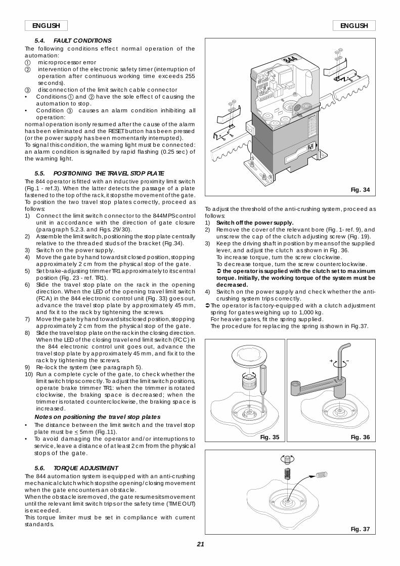
To adjust the threshold of the anti-crushing system, proceed asfollows:1) Switch off the power supply.2) Remove the cover of the relevant bore (Fig. 1- ref. 9), and
unscrew the cap of the clutch adjusting screw (Fig. 19).3) Keep the driving shaft in position by means of the supplied
lever, and adjust the clutch as shown in Fig. 36.To increase torque, turn the screw clockwise.To decrease torque, turn the screw counterclockwise.Ü the operator is supplied with the clutch set to maximumtorque. Initially, the working torque of the system must bedecreased.
4) Switch on the power supply and check whether the anti-crushing system trips correctly.
ÜThe operator is factory-equipped with a clutch adjustmentspring for gates weighing up to 1,000 kg.For heavier gates, fit the spring supplied.The procedure for replacing the spring is shown in Fig.37.
Fig. 34
Fig. 35 Fig. 36
Fig. 37
22
ENGLISH ENGLISH
6. TESTING THE AUTOMATIONWhen installation is complete, affix the danger warning label tothe top of the casing (Fig. 38).Press fit the covers over the operator fixing bars (Fig. 39).Thoroughly check operation of the automation and allconnected accessories.Give the customer the User Guide. Explain correct use andoperation of the gear motor and draw attention to the potentialdanger zones of the automation.
7. MANUAL OPERATIONIf it is necessary to operate the gate manually due to a powerfailure or malfunction of the automation, operate the releasedevice as follows.1) Open the lock cover and insert the key supplied in the lock
(Fig.40).2) Turn the key clockwise and pull out the release lever as
shown in Fig.41.3) Open or close the gate manually.
8. RETURN TO NORMAL OPERATIONTo prevent accidental operation of the gate during thisprocedure, turn off the electricity supply to the system beforerelocking the operator.1) Close the release lever.2) Turn the key anti-clockwise.3) Remove the key and close the lock cover.4) Move the gate until the release device engages.
9. SPECIAL APPLICATIONSThere are no special applications.
10. MAINTENANCEWhen performing maintenance, always check that the anti-crushing clutch is correctly adjusted and that the safety devicesoperate correctly.
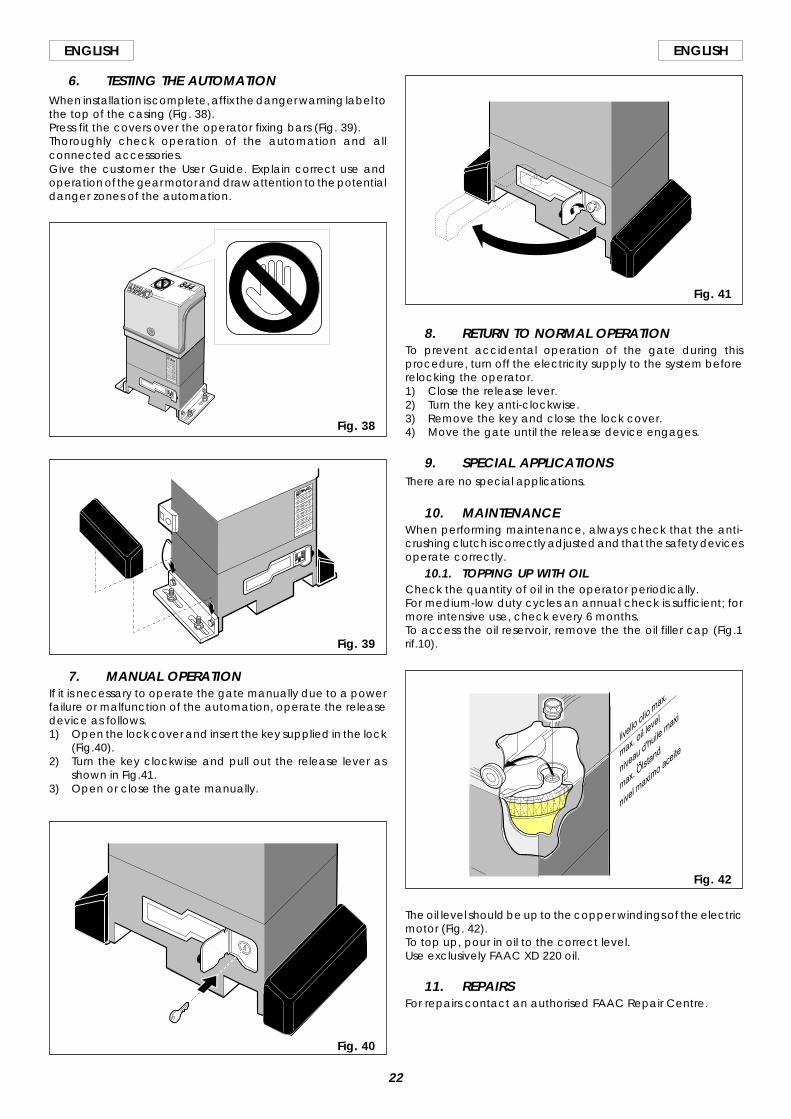
10.1. TOPPING UP WITH OILCheck the quantity of oil in the operator periodically.For medium-low duty cycles an annual check is sufficient; formore intensive use, check every 6 months.To access the oil reservoir, remove the the oil filler cap (Fig.1rif.10).
The oil level should be up to the copper windings of the electricmotor (Fig. 42).To top up, pour in oil to the correct level.Use exclusively FAAC XD 220 oil.
11. REPAIRSFor repairs contact an authorised FAAC Repair Centre.
Fig. 40
Fig. 41
Fig. 42
Fig. 38
Fig. 39
23
ENGLISHENGLISH
USER’S GUIDE
844 AUTOMATIONRead the instructions carefully before using the product andkeep them for future reference.
GENERAL SAFETY INSTRUCTIONSThe 844 automation, when installed and used correctly, affordsa high level of safety.However, some simple rules should be followed to avoidaccidents:- Do not stand in the vicinity of the automation or allow anyone
else, especially children, to do so, and do not place objectsin the vicinity of the automation. This is particularly importantduring operation.
- Keep remote controls or any other control devices out of thereach of children to prevent them from accidentally operatingthe automation.
- Do not allow children to play with the automation.- Do not deliberately obstruct the movement of the gate.- Make sure that branches or bushes do not interfere with the
movement of the gate.- Ensure that the signalling lights are efficient and clearly visible.- Do not attempt to move the gate manually without first
releasing it.- In the event of a malfunction, release the gate to allow
access and call a qualified technician for service.- After setting manual operation, disconnect the electricity
supply from the system before returning to normal operation.- Do not make any modifications to components of the
automation system.- Do not attempt to perform any repair work or tamper with the
automation. Call FAAC qualified personnel for repairs.- At least once every six months have the automation, the
safety devices and the earth connection checked by aqualified technician.
DESCRIPTIONThe FAAC 844 automation is ideal for controlling vehicle accessareas with medium-high transit frequencies.The FAAC model 844 automation for sliding gates areelectromechanical operators which transmit movement to theleaf by means of a pinion with rack or chain coupled inappropriate manner to the sliding gate.The operation of the sliding gate is controlled by an electroniccontrol unit housed inside the operator.When the gate is closed, on receipt of an opening impulse froma remote control or other suitable control device, the controlunit will start the motor to move the gate to the open position.If automatic operation has been selected, sending an impulsecauses the gate to reclose on its own after the selected pausetime.If semiautomatic operation has been selected, a secondimpulse must be sent to reclose the gate.An opening impulse sent while the gate is reclosing causes it tochange direction of movement.A stop command (if available) stops movement at any time.For detailed information on operation of the sliding gate in thevarious operating modes, contact the installation technician.The automations have safety devices (photocells) which preventthe gate from reclosing when an obstacle lies within the areathey are protecting.The system ensures mechanical locking when the motor is notin operation, so it is not necessary to install a lock.For this reason the release system must be operated before thegate can be opened manually.The gear motor has mechanical clutch which affords thenecessary anti-crushing safety.An inductive sensor detects the passage of the metal stopplates fixed to the rack in correspondence with the travel limit
positions. The electronic control unit is incorporated in the gearmotor.A convenient manual release device allows the gate to beoperated in the event of a power failure or malfunction.The light flashes while the gate is moving.
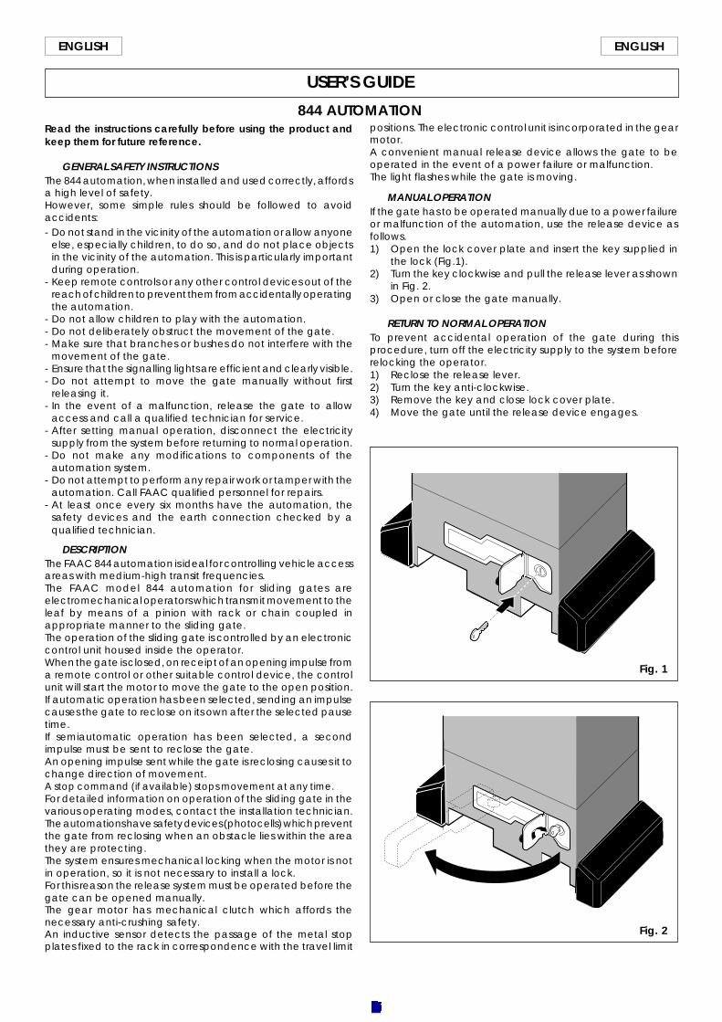
MANUAL OPERATIONIf the gate has to be operated manually due to a power failureor malfunction of the automation, use the release device asfollows.1) Open the lock cover plate and insert the key supplied in
the lock (Fig.1).2) Turn the key clockwise and pull the release lever as shown
in Fig. 2.3) Open or close the gate manually.
RETURN TO NORMAL OPERATIONTo prevent accidental operation of the gate during thisprocedure, turn off the electricity supply to the system beforerelocking the operator.1) Reclose the release lever.2) Turn the key anti-clockwise.3) Remove the key and close lock cover plate.4) Move the gate until the release device engages.
Fig. 1
Fig. 2
Recommended