I N S T A L L A T I O N I N S T R U C T I O N S
Instrucciones de instalaciónInstallationsanleitungInstruções de Instalação
Istruzioni di installazioneInstallatie-instructiesInstructions d´installation
FCA2X1UFCA3X1U
FCA3X1UP
Video Wall Add-On AccessoriesSpanish Product DescriptionGerman Product Description
Portuguese Product Description Italian Product DescriptionDutch Product Description
French Product Description
FCA2X1U-FCA3X1U-FCA3X1UP
FCA2X1U-FCA3X1U-FCA3X1UP Installation Instructions
2
DISCLAIMERMilestone AV Technologies and its affiliated corporations andsubsidiaries (collectively “Milestone”), intend to make thismanual accurate and complete. However, Milestone makes noclaim that the information contained herein covers all details,conditions or variations, nor does it provide for every possiblecontingency in connection with the installation or use of thisproduct. The information contained in this document is subjectto change without notice or obligation of any kind. Milestonemakes no representation of warranty, expressed or implied,regarding the information contained herein. Milestone assumesno responsibility for accuracy, completeness or sufficiency ofthe information contained in this document.
Chief® is a registered trademark of Milestone AV Technologies.All rights reserved.
IMPORTANT SAFETY INSTRUCTIONS
WARNING: A WARNING alerts you to the possibility ofserious injury or death if you do not follow the instructions.
CAUTION: A CAUTION alerts you to the possibility ofdamage or destruction of equipment if you do not follow thecorresponding instructions.
WARNING: Failure to read, thoroughly understand, andfollow all instructions can result in serious personal injury,damage to equipment, or voiding of factory warranty! It is theinstaller’s responsibility to make sure all components areproperly assembled and installed using the instructionsprovided.
WARNING: Failure to provide adequate structural strengthfor this component can result in serious personal injury ordamage to equipment! It is the installer’s responsibility tomake sure the structure to which this component is attachedcan support five times the combined weight of all equipment.Reinforce the structure as required before installing thecomponent.
WARNING: Do NOT stack multiple accessories on thesame display cart! Do NOT connect accessories to carts thatare already three display high. Display carts may NOT bestacked higher than three displays high! Portrait versionsmay NOT be stacked higher than two displays high!
WARNING: RISK OF SERIOUS INJURY OR DEATH!Placing a remote control or toy on the cart may encourage achild to climb onto the cart causing the cart to tip over ontothe child. DO NOT place remote controls or toys on the cart!
WARNING: RISK OF SERIOUS INJURY OR DEATH!Relocating audio and/or video equipment to the cart mayresult in the cart collapsing or overturning onto a child. DONOT relocate audio and/or video equipment to the cart!
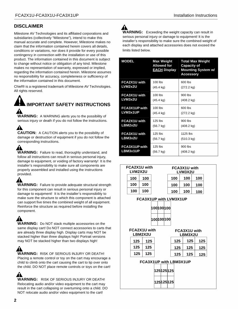
WARNING: Exceeding the weight capacity can result inserious personal injury or damage to equipment! It is theinstaller’s responsibility to make sure the combined weight ofeach display and attached accessories does not exceed thelimits listed below.
MODEL Max WeightAllowed forEACH Display
Total Max WeightCapacity ofMounting System w/Accessory
FCA2X1U withLVM2x2U
100 lbs
(45.4 kg)
600 lbs
(272.2 kg)
FCA3X1U withLVM3x2U
100 lbs(45.4 kg)
900 lbs(408.2 kg)
FCA3X1UP withLVM3x1UP
100 lbs
(45.4 kg)
600 lbs
(272.2 kg)
FCA2X1U withLBM2x2U
125 lbs(56.7 kg)
900 lbs(408.2 kg)
FCA3X1U withLBM3x2U
125 lbs
(56.7 kg)
1125 lbs
(510.3 kg)
FCA3X1UP withLBM3x1UP
125 lbs(56.7 kg)
900 lbs(408.2 kg)
LVM2X2U LVM3X2U100 100
100100100 100 100
100100100100 100 100
100100100
100100100
FCA2X1U with FCA3X1U with
FCA3X1UP with LVM3X1UP
100 100
LBM2X2U LBM3X2U125 125
125125125 125 125
125125125125 125 125
125125125
125125125
FCA2X1U with FCA3X1U with
FCA3X1UP with LBM3X1UP
125 125
Installation Instructions FCA2X1U-FCA3X1U-FCA3X1UP
3
WARNING: RISK OF SERIOUS INJURY OR DEATH! Usewith televisions weighing more than the maximum weightindicated may result in the cart collapsing or overturning ontoa person causing serious injury or death!
WARNING: Do not use this product outdoors.
NOTE: The FCA2X1U, FCA3X1U and FCA3X1UP have nouser serviceable parts.
NOTE: The UL Listed FCA add-on row may be used with thefollowing UL Listed models: FCA2X1U may be usedwith LVM2X2U and LBM2X2U. FCA3X1U may be usedwith LVM3X2U and LBM3X2U. FCA3X1UP may beused with LVM3X1UP and LBM3X1UP.
NOTE: The UL listed FCA add-on row may be used with the ULListed FCAX08, FCAX14 and FCAX20 horizontalextension brackets (not included).
--SAVE THESE INSTRUCTIONS--
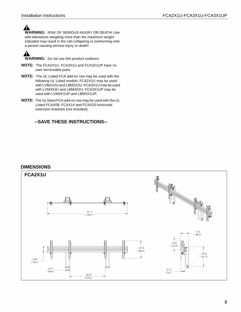
DIMENSIONS
3.7795.8
FCA2X1U
Installation Instructions FCA2X1U-FCA3X1U-FCA3X1UP
4
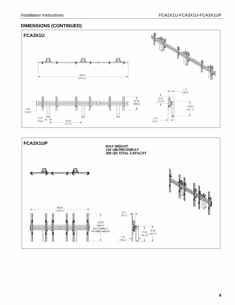
DIMENSIONS (CONTINUED)
15.75400.0
FCA3X1U
31.50800.0
MAX DISPLAYPATTERN HEIGHT
68.001727.2
MAX WEIGHT:100 LBS PER DISPLAY
FCA3X1UP
FCA2X1U-FCA3X1U-FCA3X1UP Installation Instructions
5
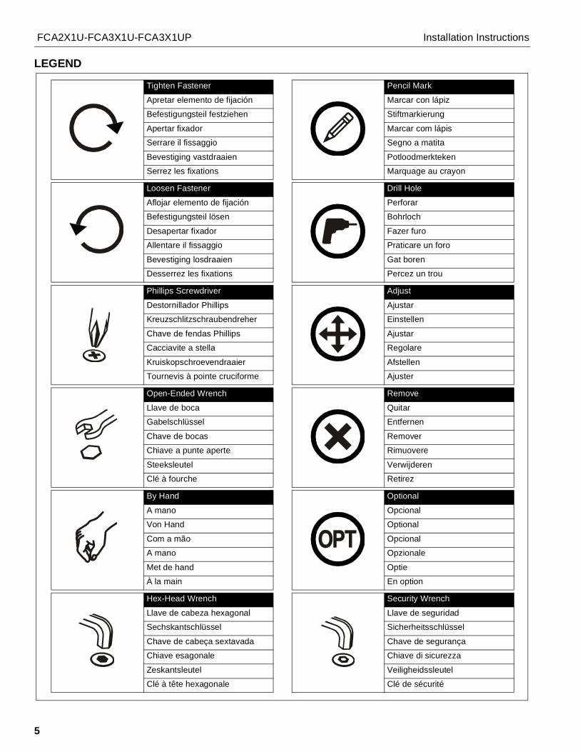
LEGEND
Tighten Fastener
Apretar elemento de fijación
Befestigungsteil festziehen
Apertar fixador
Serrare il fissaggio
Bevestiging vastdraaien
Serrez les fixations
Loosen Fastener
Aflojar elemento de fijación
Befestigungsteil lösen
Desapertar fixador
Allentare il fissaggio
Bevestiging losdraaien
Desserrez les fixations
Phillips Screwdriver
Destornillador Phillips
Kreuzschlitzschraubendreher
Chave de fendas Phillips
Cacciavite a stella
Kruiskopschroevendraaier
Tournevis à pointe cruciforme
Open-Ended Wrench
Llave de boca
Gabelschlüssel
Chave de bocas
Chiave a punte aperte
Steeksleutel
Clé à fourche
By Hand
A mano
Von Hand
Com a mão
A mano
Met de hand
À la main
Hex-Head Wrench
Llave de cabeza hexagonal
Sechskantschlüssel
Chave de cabeça sextavada
Chiave esagonale
Zeskantsleutel
Clé à tête hexagonale
Pencil Mark
Marcar con lápiz
Stiftmarkierung
Marcar com lápis
Segno a matita
Potloodmerkteken
Marquage au crayon
Drill Hole
Perforar
Bohrloch
Fazer furo
Praticare un foro
Gat boren
Percez un trou
Adjust
Ajustar
Einstellen
Ajustar
Regolare
Afstellen
Ajuster
Remove
Quitar
Entfernen
Remover
Rimuovere
Verwijderen
Retirez
Optional
Opcional
Optional
Opcional
Opzionale
Optie
En option
Security Wrench
Llave de seguridad
Sicherheitsschlüssel
Chave de segurança
Chiave di sicurezza
Veiligheidssleutel
Clé de sécurité
FCA2X1U-FCA3X1U-FCA3X1UP Installation Instructions
6
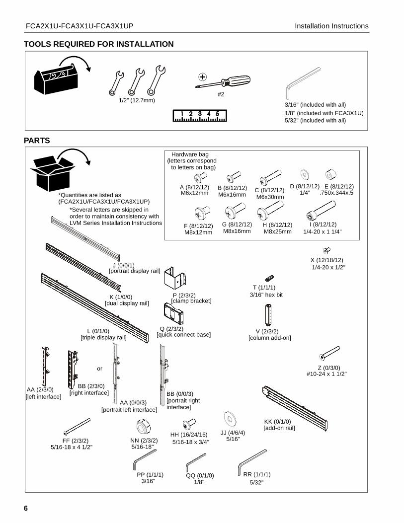
TOOLS REQUIRED FOR INSTALLATION
PARTS
#21/2" (12.7mm)
3/16" (included with all)1/8" (included with FCA3X1U)5/32" (included with all)
Hardware bag(letters correspond
to letters on bag)
A (8/12/12)*Quantities are listed as(FCA2X1U/FCA3X1U/FCA3X1UP)
M6x12mmB (8/12/12)M6x16mm
C (8/12/12)M6x30mm
D (8/12/12)1/4"
E (8/12/12).750x.344x.5
F (8/12/12)M8x12mm
G (8/12/12)M8x16mm
H (8/12/12)M8x25mm
I (8/12/12)1/4-20 x 1 1/4"
K (1/0/0)[dual display rail]
L (0/1/0)[triple display rail]
P (2/3/2)[clamp bracket]
Q (2/3/2)[quick connect base]
T (1/1/1)3/16" hex bit
V (2/3/2)[column add-on]
X (12/18/12)1/4-20 x 1/2"
Z (0/3/0)#10-24 x 1 1/2"
AA (2/3/0)[left interface]
BB (2/3/0)[right interface]
FF (2/3/2)5/16-18 x 4 1/2"
HH (16/24/16)5/16-18 x 3/4"
JJ (4/6/4)5/16"
KK (0/1/0)[add-on rail]
NN (2/3/2)5/16-18"
PP (1/1/1)3/16"
QQ (0/1/0)1/8"
RR (1/1/1)5/32"
*Several letters are skipped inorder to maintain consistency withLVM Series Installation Instructions
or
AA (0/0/3)[portrait left interface]
BB (0/0/3)[portrait rightinterface]
J (0/0/1)[portrait display rail]
Installation Instructions FCA2X1U-FCA3X1U-FCA3X1UP
7
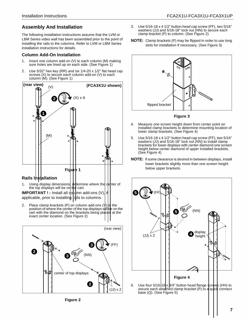
Assembly And InstallationThe following installation instructions assume that the LVM orLBM Series video wall has been assembled prior to the point ofinstalling the rails to the columns. Refer to LVM or LBM Seriesinstallation instructions for details.
Column Add-On Installation1. Insert one column add-on (V) to each column (M) making
sure holes are lined up on each side. (See Figure 1)
2. Use 5/32" hex key (RR) and six 1/4-20 x 1/2" flat head capscrews (X) to secure each column add-on (V) to eachcolumn (M). (See Figure 1)
Figure 1
Rails Installation1. Using display dimensions, determine where the center of
the top displays will be on the cart.IMPORTANT ! : Install all column add-ons (V), ifapplicable, prior to installing rails to columns.
2. Place clamp brackets (P) on column add-ons (V) in theposition of where the center of the top displays will be on thecart with the diamond on the brackets being placed at theexact center location. (See Figure 2)
Figure 2
3. Use 5/16-18 x 4 1/2" button head cap screw (FF), two 5/16"washers (JJ) and 5/16-18" lock nut (NN) to secure eachclamp bracket (P) to column. (See Figure 2)
NOTE: Clamp brackets (P) may be flipped in order to use longslots for installation if necessary. (See Figure 3)
Figure 3
4. Measure one screen height down from center point oninstalled clamp brackets to determine mounting location oflower clamp brackets. (See Figure 4)
5. Use 5/16-18 x 4 1/2" button head cap screw (FF), two 5/16"washers (JJ) and 5/16-18" lock nut (NN) to install clampbrackets for lower displays with center diamond one screenheight below center diamond of upper installed brackets.(See Figure 4)
NOTE: If some clearance is desired in between displays, installlower brackets slightly more than one screen heightbelow upper brackets.
Figure 4
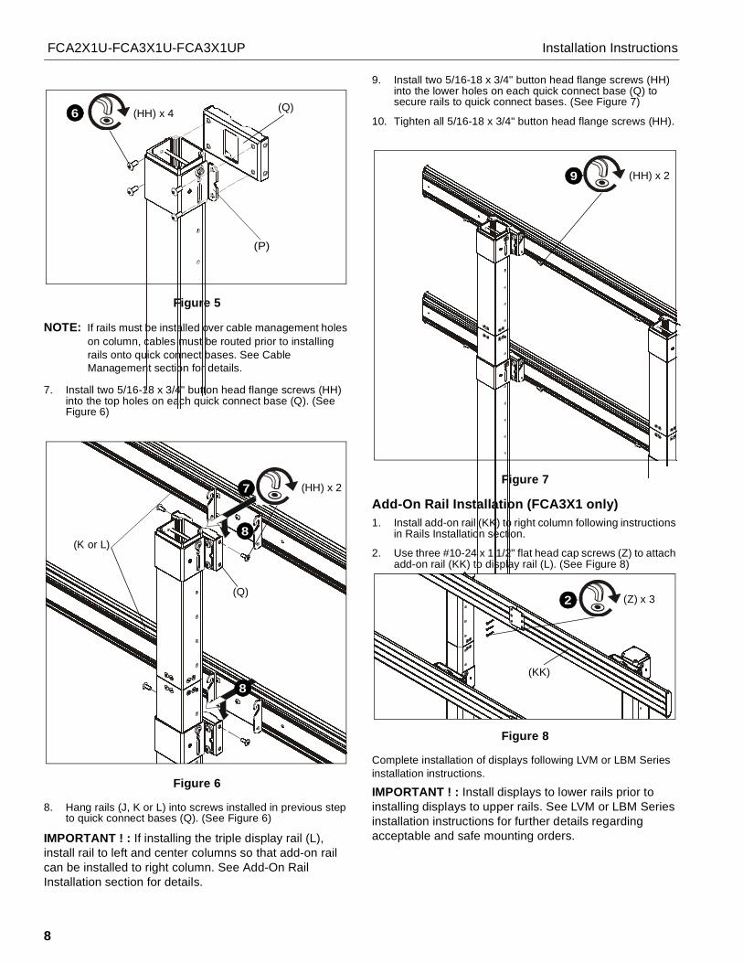
6. Use four 5/16-18 x 3/4" button head flange screws (HH) tosecure each attached clamp bracket (P) to a quick connectbase (Q). (See Figure 5)
(rear view) (V)
1
2 (X) x 6
(M)
(FCA3X1U shown)
2
2
(rear view)
(FF)
(NN)
3
3
(JJ) x 2
center of top displays
flipped bracket
(FF)
(NN)
5
5
(JJ) x 2displayheight4
FCA2X1U-FCA3X1U-FCA3X1UP Installation Instructions
8
Figure 5
NOTE: If rails must be installed over cable management holeson column, cables must be routed prior to installingrails onto quick connect bases. See CableManagement section for details.
7. Install two 5/16-18 x 3/4" button head flange screws (HH)into the top holes on each quick connect base (Q). (SeeFigure 6)
Figure 6
8. Hang rails (J, K or L) into screws installed in previous stepto quick connect bases (Q). (See Figure 6)
IMPORTANT ! : If installing the triple display rail (L),install rail to left and center columns so that add-on railcan be installed to right column. See Add-On RailInstallation section for details.
9. Install two 5/16-18 x 3/4" button head flange screws (HH)into the lower holes on each quick connect base (Q) tosecure rails to quick connect bases. (See Figure 7)
10. Tighten all 5/16-18 x 3/4" button head flange screws (HH).
Figure 7
Add-On Rail Installation (FCA3X1 only)1. Install add-on rail (KK) to right column following instructions
in Rails Installation section.
2. Use three #10-24 x 1 1/2" flat head cap screws (Z) to attachadd-on rail (KK) to display rail (L). (See Figure 8)
Figure 8
Complete installation of displays following LVM or LBM Seriesinstallation instructions.
IMPORTANT ! : Install displays to lower rails prior toinstalling displays to upper rails. See LVM or LBM Seriesinstallation instructions for further details regardingacceptable and safe mounting orders.
(Q)(HH) x 46
(P)
(HH) x 2
8
8
7
(Q)
(K or L)
(HH) x 29
(Z) x 32
(KK)

Installation Instructions FCA2X1U-FCA3X1U-FCA3X1UP
9

FCA2X1U-FCA3X1U-FCA3X1UP Installation Instructions
10

Installation Instructions FCA2X1U-FCA3X1U-FCA3X1UP
11
FCA2X1U-FCA3X1U-FCA3X1UP Installation Instructions
USA/International A 6436 City West Parkway, Eden Prairie, MN 55344P 800.582.6480 / 952.225.6000F 877.894.6918 / 952.894.6918
Europe A Franklinstraat 14, 6003 DK Weert, NetherlandsP +31 (0) 495 580 852F +31 (0) 495 580 845
Asia Pacific A Office No. 918 on 9/F, Shatin Galleria18-24 Shan Mei StreetFotan, Shatin, Hong Kong
P 852 2145 4099F 852 2145 4477
Chief, a products division ofMilestone AV Technologies
8800-002393 Rev012014 Milestone AV Technologies
www.chiefmfg.com05/14
Recommended