Embed Size (px)
Citation preview
[email protected] • ENGR-22_Lec-20__Fasteners-1_Specs.ppt1
Bruce Mayer, PE Engineering 22 – Engineering Design Graphics
Bruce Mayer, PERegistered Electrical & Mechanical Engineer
Engineering 22
ThreadedThreadedFastenersFasteners
[email protected] • ENGR-22_Lec-20__Fasteners-1_Specs.ppt2
Bruce Mayer, PE Engineering 22 – Engineering Design Graphics
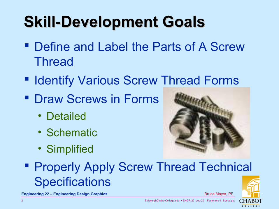
Skill-Development GoalsSkill-Development Goals
Define and Label the Parts of A Screw Thread
Identify Various Screw Thread Forms
Draw Screws in Forms• Detailed
• Schematic
• Simplified
Properly Apply Screw Thread Technical Specifications
[email protected] • ENGR-22_Lec-20__Fasteners-1_Specs.ppt3
Bruce Mayer, PE Engineering 22 – Engineering Design Graphics
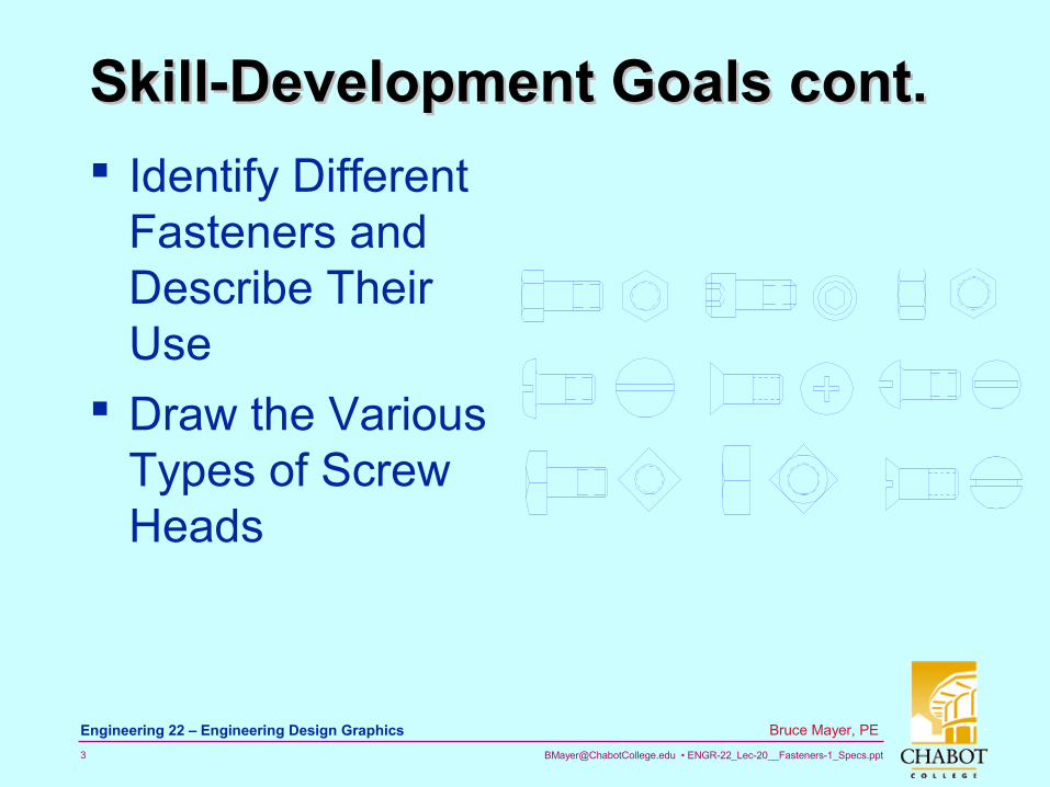
Skill-Development Goals cont.Skill-Development Goals cont.
Identify Different Fasteners and Describe Their Use
Draw the Various Types of Screw Heads
[email protected] • ENGR-22_Lec-20__Fasteners-1_Specs.ppt4
Bruce Mayer, PE Engineering 22 – Engineering Design Graphics
Skill-Development GoalsSkill-Development Goals State the Two MOST Important
Threaded Fastener References for Structural (Mech/Civ/Chem) Design Engineers
Use AutoCAD to QUICKLY Draw Most Threaded Fasteners in Any Size and Any Representation
Invoke the AutoCAD “Design Center” tool to Construct Fastener Representations
[email protected] • ENGR-22_Lec-20__Fasteners-1_Specs.ppt5
Bruce Mayer, PE Engineering 22 – Engineering Design Graphics
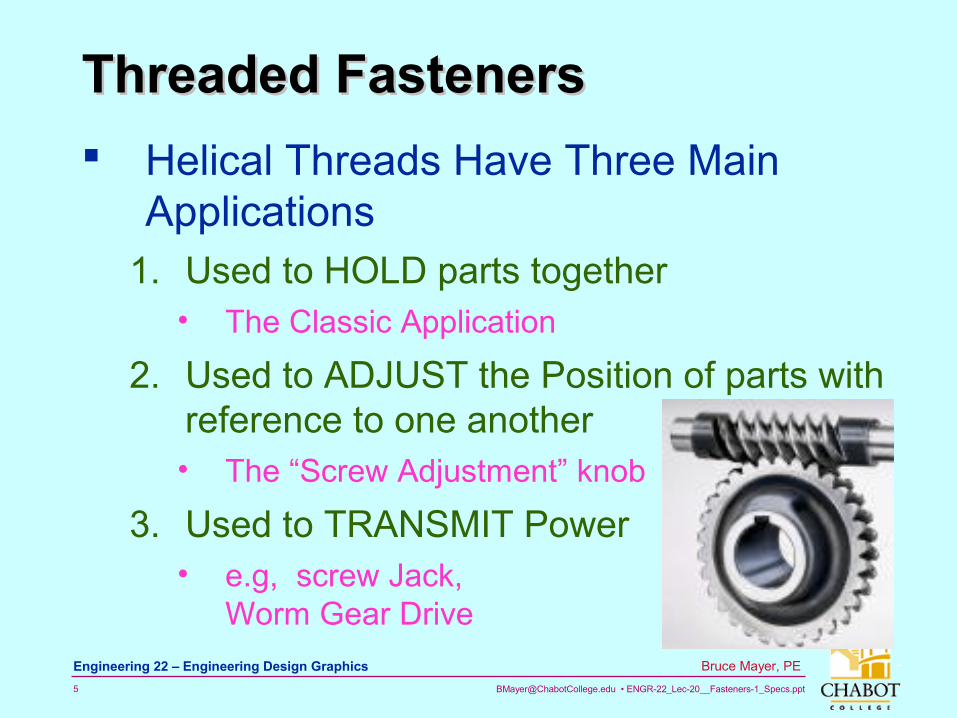
Threaded FastenersThreaded Fasteners
Helical Threads Have Three Main Applications
1. Used to HOLD parts together• The Classic Application
2. Used to ADJUST the Position of parts with reference to one another• The “Screw Adjustment” knob
3. Used to TRANSMIT Power• e.g, screw Jack,
Worm Gear Drive
[email protected] • ENGR-22_Lec-20__Fasteners-1_Specs.ppt6
Bruce Mayer, PE Engineering 22 – Engineering Design Graphics
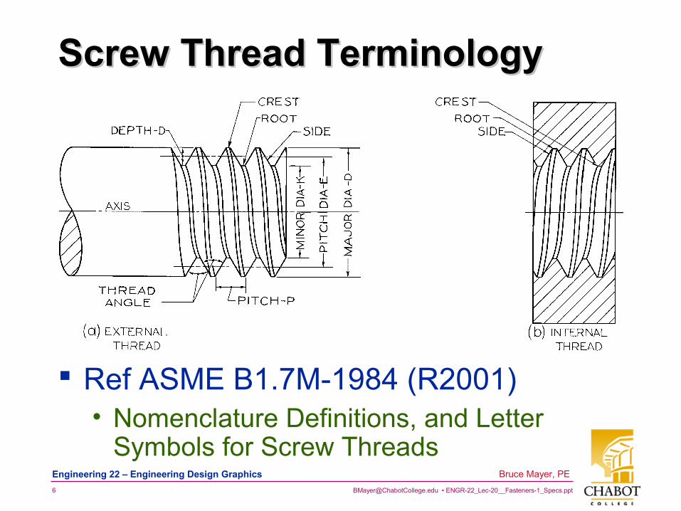
Screw Thread TerminologyScrew Thread Terminology
Ref ASME B1.7M-1984 (R2001) • Nomenclature Definitions, and Letter
Symbols for Screw Threads
[email protected] • ENGR-22_Lec-20__Fasteners-1_Specs.ppt7
Bruce Mayer, PE Engineering 22 – Engineering Design Graphics
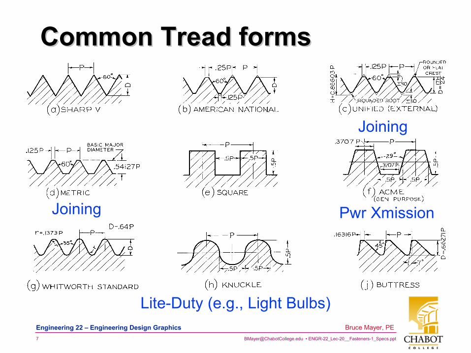
Common Tread formsCommon Tread forms
Joining
Joining
Lite-Duty (e.g., Light Bulbs)
Pwr Xmission
[email protected] • ENGR-22_Lec-20__Fasteners-1_Specs.ppt8
Bruce Mayer, PE Engineering 22 – Engineering Design Graphics
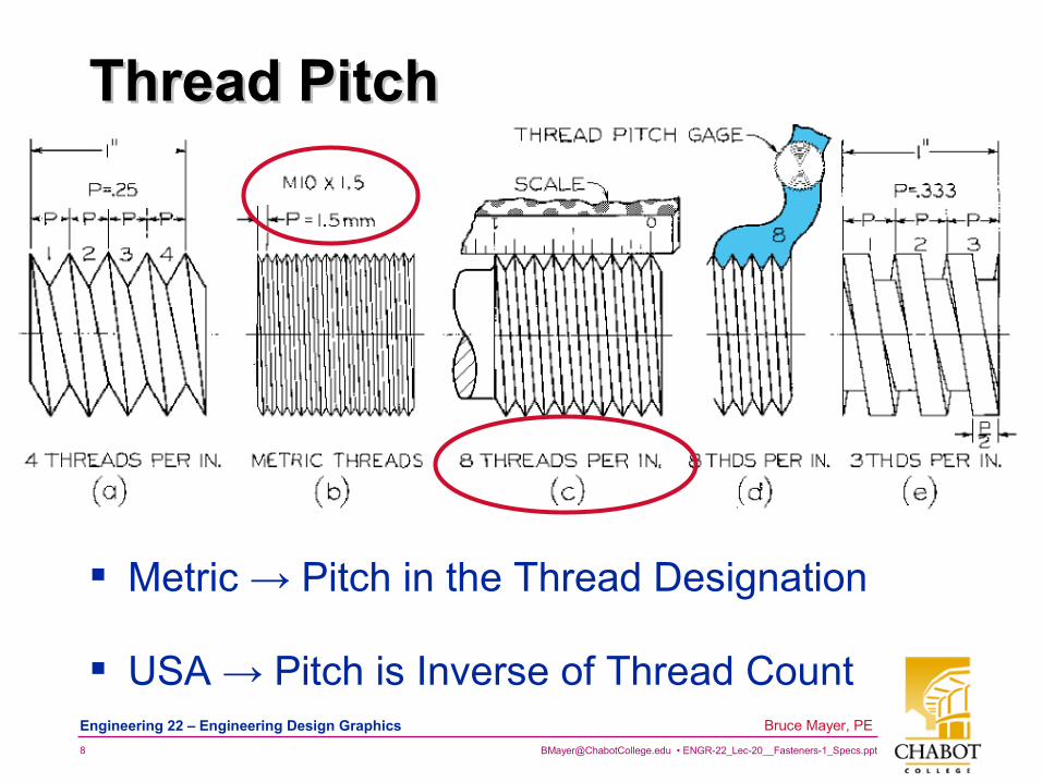
Thread PitchThread Pitch
USA → Pitch is Inverse of Thread Count
Metric → Pitch in the Thread Designation
[email protected] • ENGR-22_Lec-20__Fasteners-1_Specs.ppt9
Bruce Mayer, PE Engineering 22 – Engineering Design Graphics
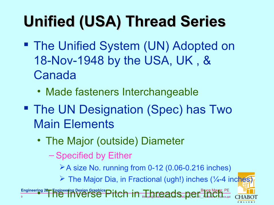
Unified (USA) Thread SeriesUnified (USA) Thread Series
The Unified System (UN) Adopted on 18-Nov-1948 by the USA, UK , & Canada• Made fasteners Interchangeable
The UN Designation (Spec) has Two Main Elements• The Major (outside) Diameter
– Specified by EitherA size No. running from 0-12 (0.06-0.216 inches)
The Major Dia, in Fractional (ugh!) inches (¼-4 inches)
• The Inverse Pitch in Threads per Inch
[email protected] • ENGR-22_Lec-20__Fasteners-1_Specs.ppt10
Bruce Mayer, PE Engineering 22 – Engineering Design Graphics
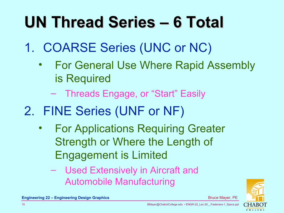
UN Thread Series – 6 TotalUN Thread Series – 6 Total
1. COARSE Series (UNC or NC)• For General Use Where Rapid Assembly
is Required– Threads Engage, or “Start” Easily
2. FINE Series (UNF or NF)• For Applications Requiring Greater
Strength or Where the Length of Engagement is Limited
– Used Extensively in Aircraft and Automobile Manufacturing
[email protected] • ENGR-22_Lec-20__Fasteners-1_Specs.ppt11
Bruce Mayer, PE Engineering 22 – Engineering Design Graphics
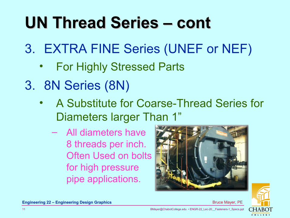
UN Thread Series – contUN Thread Series – cont
3. EXTRA FINE Series (UNEF or NEF)• For Highly Stressed Parts
3. 8N Series (8N)• A Substitute for Coarse-Thread Series for
Diameters larger Than 1”– All diameters have
8 threads per inch. Often Used on bolts for high pressure pipe applications.
[email protected] • ENGR-22_Lec-20__Fasteners-1_Specs.ppt12
Bruce Mayer, PE Engineering 22 – Engineering Design Graphics
UN Thread Series – cont.2UN Thread Series – cont.2
5. 12N Series (12 UN or 12N)• A Continuation of the Fine-Thread Series
for Diameters Larger than 1.5”– All diameters have 12 thds/in. Used in boiler
work and in Machine Construction.
5. 16N Series (16 UN or 16N)• A Continuation of the ExtraFine-Thread
Series for Diameters Larger than 2”– All diameters have 16 thds/in. Used on
adjusting collars and other applications where thread must have fine adjustment regardless of diameter.
[email protected] • ENGR-22_Lec-20__Fasteners-1_Specs.ppt13
Bruce Mayer, PE Engineering 22 – Engineering Design Graphics
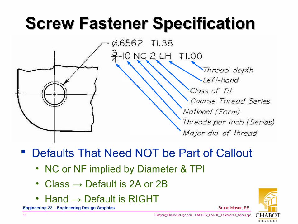
Screw Fastener SpecificationScrew Fastener Specification
Defaults That Need NOT be Part of Callout• NC or NF implied by Diameter & TPI
• Class → Default is 2A or 2B
• Hand → Default is RIGHT
[email protected] • ENGR-22_Lec-20__Fasteners-1_Specs.ppt14
Bruce Mayer, PE Engineering 22 – Engineering Design Graphics
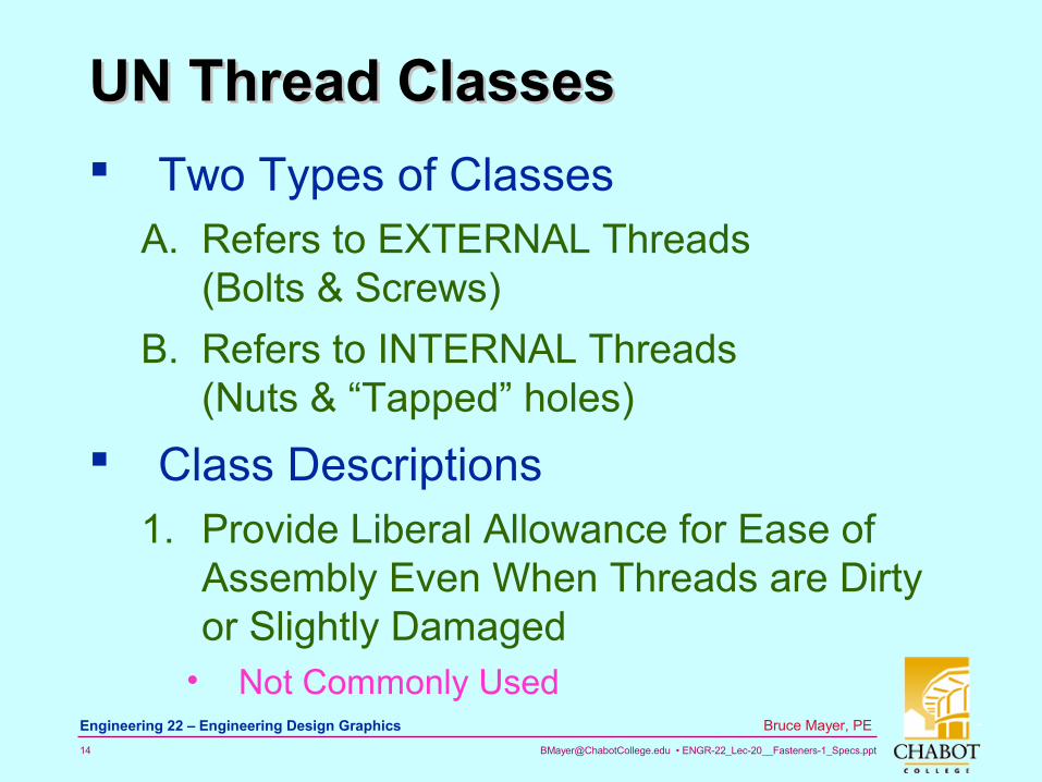
UN Thread ClassesUN Thread Classes
Two Types of ClassesA. Refers to EXTERNAL Threads
(Bolts & Screws)
B. Refers to INTERNAL Threads (Nuts & “Tapped” holes)
Class Descriptions1. Provide Liberal Allowance for Ease of
Assembly Even When Threads are Dirty or Slightly Damaged
• Not Commonly Used
[email protected] • ENGR-22_Lec-20__Fasteners-1_Specs.ppt15
Bruce Mayer, PE Engineering 22 – Engineering Design Graphics
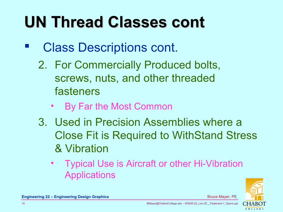
UN Thread Classes contUN Thread Classes cont
Class Descriptions cont.2. For Commercially Produced bolts,
screws, nuts, and other threaded fasteners
• By Far the Most Common
3. Used in Precision Assemblies where a Close Fit is Required to WithStand Stress & Vibration
• Typical Use is Aircraft or other Hi-Vibration Applications
[email protected] • ENGR-22_Lec-20__Fasteners-1_Specs.ppt16
Bruce Mayer, PE Engineering 22 – Engineering Design Graphics
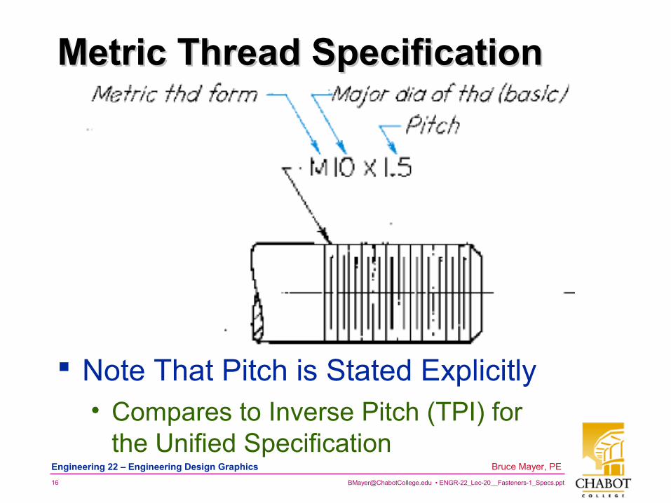
Metric Thread SpecificationMetric Thread Specification
Note That Pitch is Stated Explicitly• Compares to Inverse Pitch (TPI) for
the Unified Specification
[email protected] • ENGR-22_Lec-20__Fasteners-1_Specs.ppt17
Bruce Mayer, PE Engineering 22 – Engineering Design Graphics
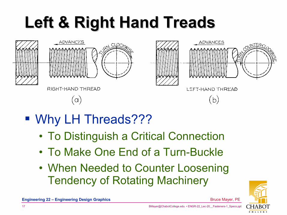
Left & Right Hand Treads Left & Right Hand Treads
Why LH Threads???• To Distinguish a Critical Connection
• To Make One End of a Turn-Buckle
• When Needed to Counter Loosening Tendency of Rotating Machinery
[email protected] • ENGR-22_Lec-20__Fasteners-1_Specs.ppt18
Bruce Mayer, PE Engineering 22 – Engineering Design Graphics
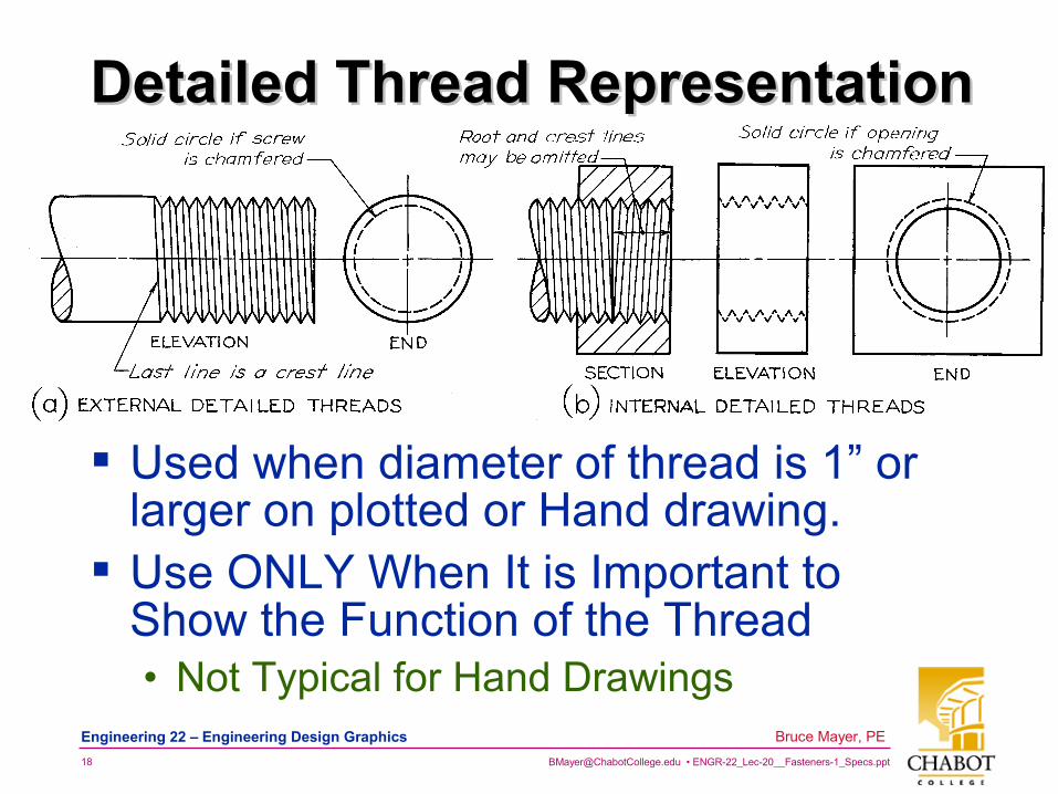
Detailed Thread Representation Detailed Thread Representation
Used when diameter of thread is 1” or larger on plotted or Hand drawing.
Use ONLY When It is Important to Show the Function of the Thread• Not Typical for Hand Drawings
[email protected] • ENGR-22_Lec-20__Fasteners-1_Specs.ppt19
Bruce Mayer, PE Engineering 22 – Engineering Design Graphics
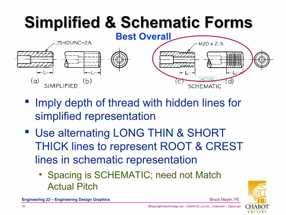
Simplified & Schematic Forms Simplified & Schematic Forms Best Overall
Imply depth of thread with hidden lines for simplified representation
Use alternating LONG THIN & SHORT THICK lines to represent ROOT & CREST lines in schematic representation• Spacing is SCHEMATIC; need not Match
Actual Pitch
[email protected] • ENGR-22_Lec-20__Fasteners-1_Specs.ppt20
Bruce Mayer, PE Engineering 22 – Engineering Design Graphics
Representation ComparisonRepresentation Comparison
Detailed → Very Laborious to Construct• Very Infrequently Used on
Engineering Drawings
Simplified → Fast but Potentially Confusing• Hidden Lines can be Mistaken for
Object Features
Schematic → Best Overall• Fast To Draw, Clearly ID’s the Threads
[email protected] • ENGR-22_Lec-20__Fasteners-1_Specs.ppt21
Bruce Mayer, PE Engineering 22 – Engineering Design Graphics
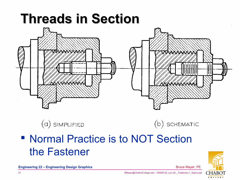
Threads in Section Threads in Section
Normal Practice is to NOT Section the Fastener

[email protected] • ENGR-22_Lec-20__Fasteners-1_Specs.ppt22
Bruce Mayer, PE Engineering 22 – Engineering Design Graphics
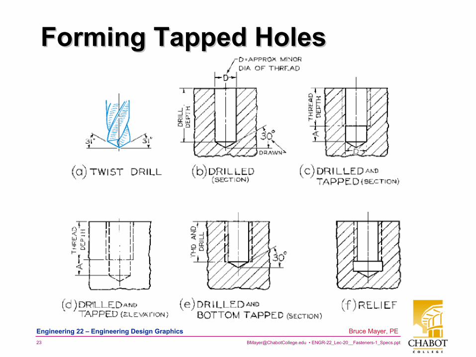
Tapped HolesTapped Holes
To Avoid the use of a Thru-Hole & Nut, The “Parent” Material of An object May be Thread “Tapped”• That is, Threads are Cut Into the Side of a
Hole Drilled into the Base Material
Even Thin parts may tapped By Use of A thru Hole• Rule of Thumb for the MINIMUM number
of threads = 3– For Light-Duty applications, can use 1.5
[email protected] • ENGR-22_Lec-20__Fasteners-1_Specs.ppt23
Bruce Mayer, PE Engineering 22 – Engineering Design Graphics
Forming Tapped HolesForming Tapped Holes
[email protected] • ENGR-22_Lec-20__Fasteners-1_Specs.ppt24
Bruce Mayer, PE Engineering 22 – Engineering Design Graphics
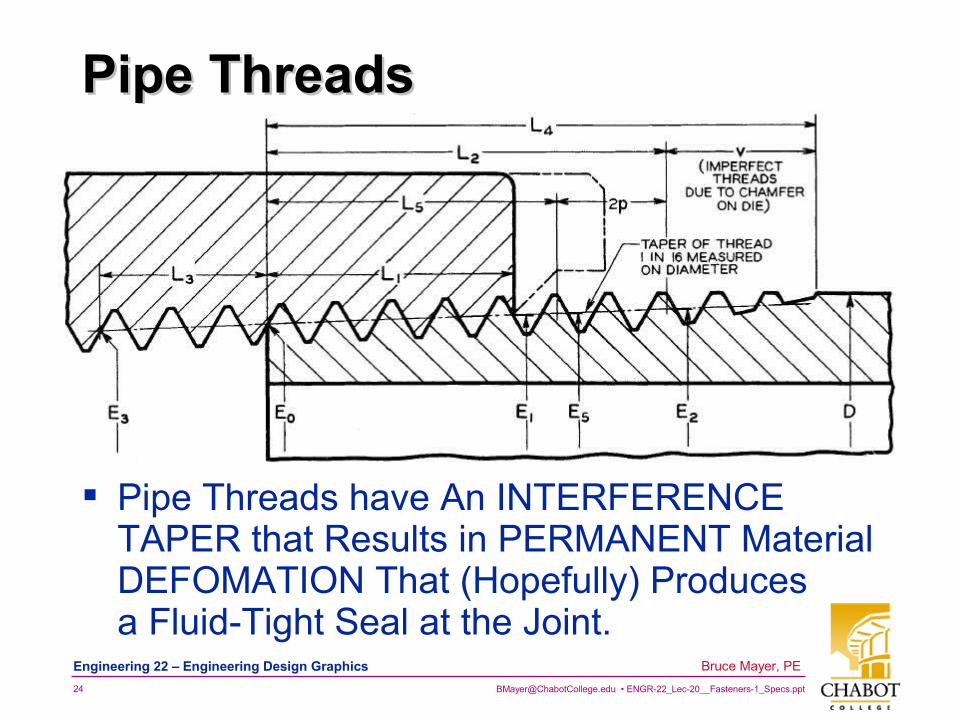
Pipe ThreadsPipe Threads
Pipe Threads have An INTERFERENCE TAPER that Results in PERMANENT Material DEFOMATION That (Hopefully) Produces a Fluid-Tight Seal at the Joint.
[email protected] • ENGR-22_Lec-20__Fasteners-1_Specs.ppt25
Bruce Mayer, PE Engineering 22 – Engineering Design Graphics
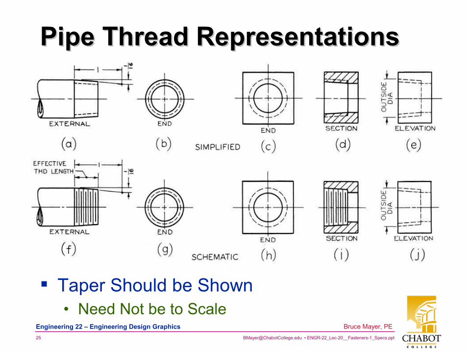
Pipe Thread RepresentationsPipe Thread Representations
Taper Should be Shown• Need Not be to Scale
[email protected] • ENGR-22_Lec-20__Fasteners-1_Specs.ppt26
Bruce Mayer, PE Engineering 22 – Engineering Design Graphics
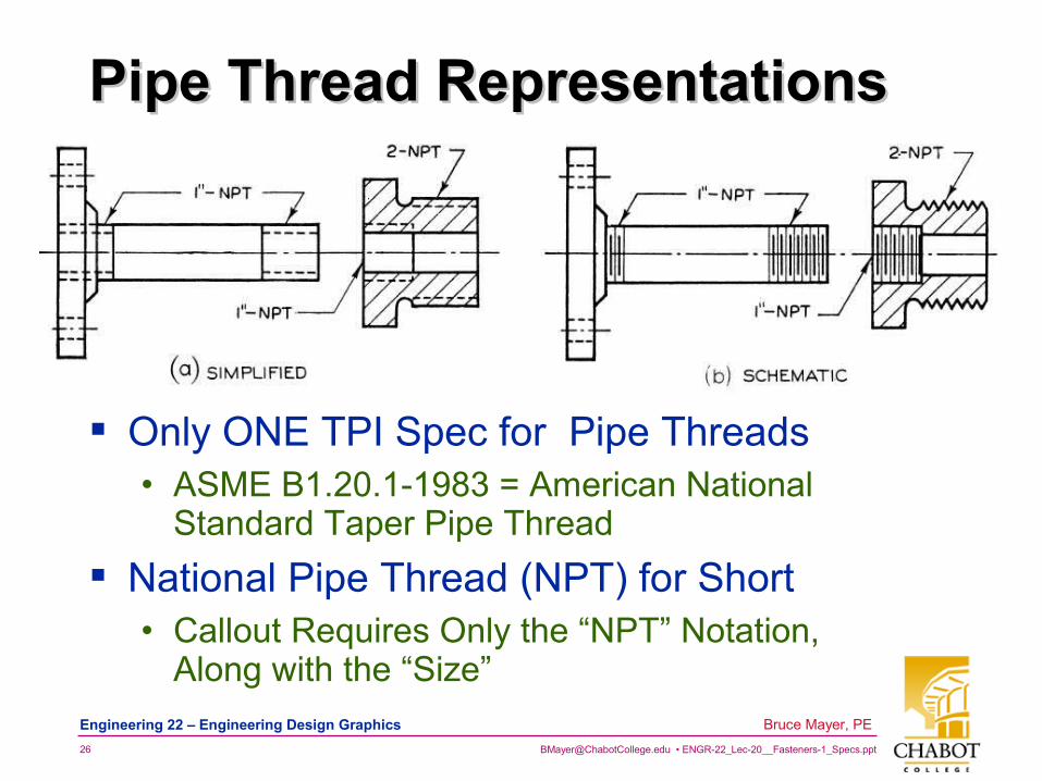
Pipe Thread RepresentationsPipe Thread Representations
Only ONE TPI Spec for Pipe Threads• ASME B1.20.1-1983 = American National
Standard Taper Pipe Thread
National Pipe Thread (NPT) for Short• Callout Requires Only the “NPT” Notation,
Along with the “Size”
[email protected] • ENGR-22_Lec-20__Fasteners-1_Specs.ppt27
Bruce Mayer, PE Engineering 22 – Engineering Design Graphics
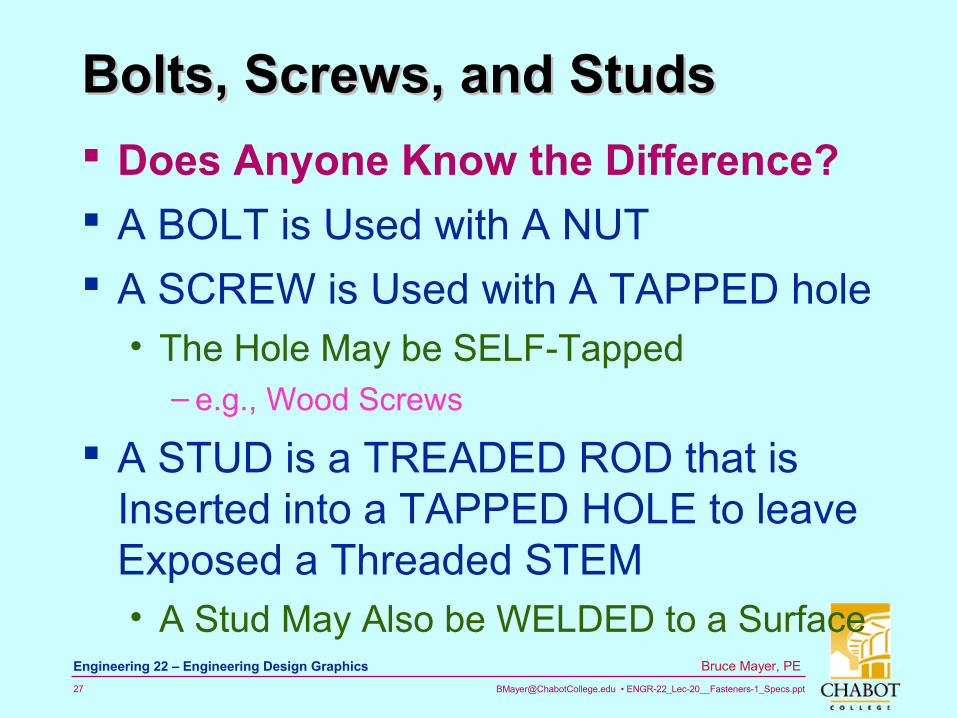
Bolts, Screws, and StudsBolts, Screws, and Studs
Does Anyone Know the Difference?
A BOLT is Used with A NUT
A SCREW is Used with A TAPPED hole• The Hole May be SELF-Tapped
– e.g., Wood Screws
A STUD is a TREADED ROD that is Inserted into a TAPPED HOLE to leave Exposed a Threaded STEM• A Stud May Also be WELDED to a Surface
[email protected] • ENGR-22_Lec-20__Fasteners-1_Specs.ppt28
Bruce Mayer, PE Engineering 22 – Engineering Design Graphics
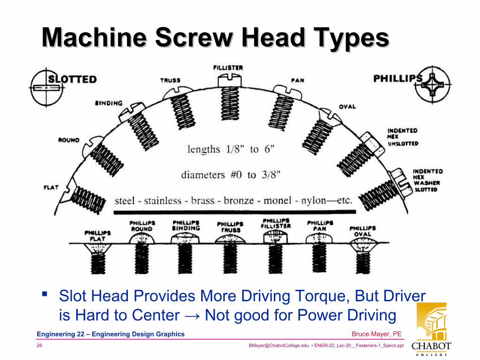
Machine Screw Head TypesMachine Screw Head Types
Slot Head Provides More Driving Torque, But Driver is Hard to Center → Not good for Power Driving
[email protected] • ENGR-22_Lec-20__Fasteners-1_Specs.ppt29
Bruce Mayer, PE Engineering 22 – Engineering Design Graphics
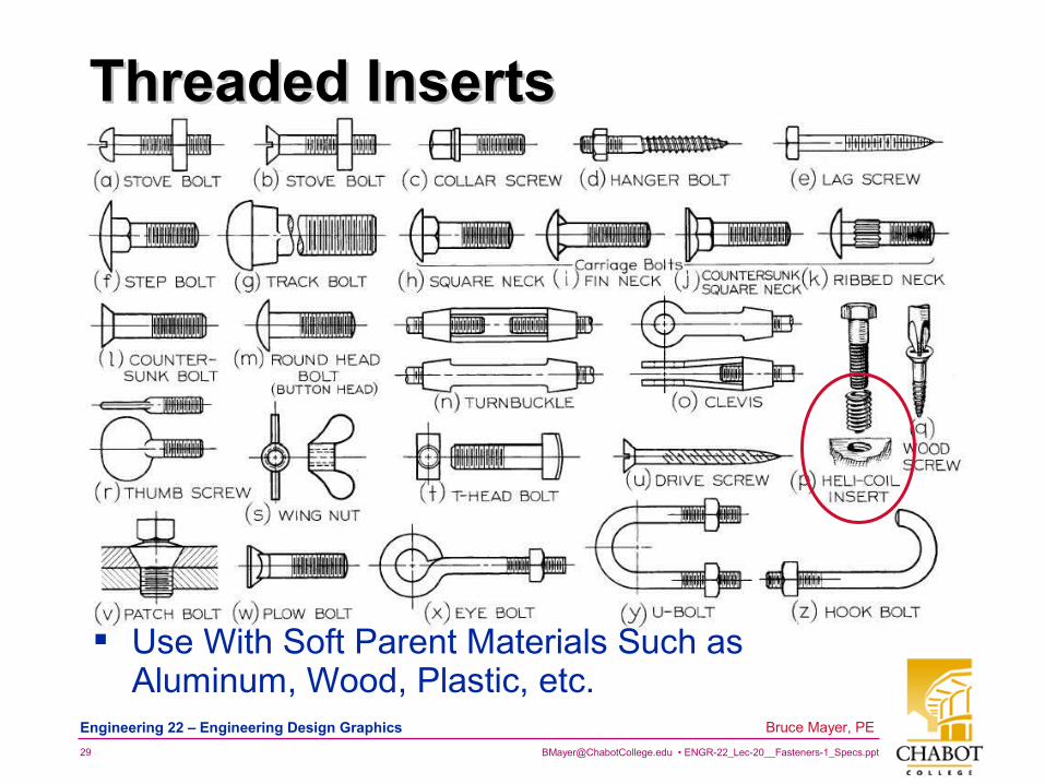
Threaded InsertsThreaded Inserts
Use With Soft Parent Materials Such as Aluminum, Wood, Plastic, etc.
[email protected] • ENGR-22_Lec-20__Fasteners-1_Specs.ppt30
Bruce Mayer, PE Engineering 22 – Engineering Design Graphics
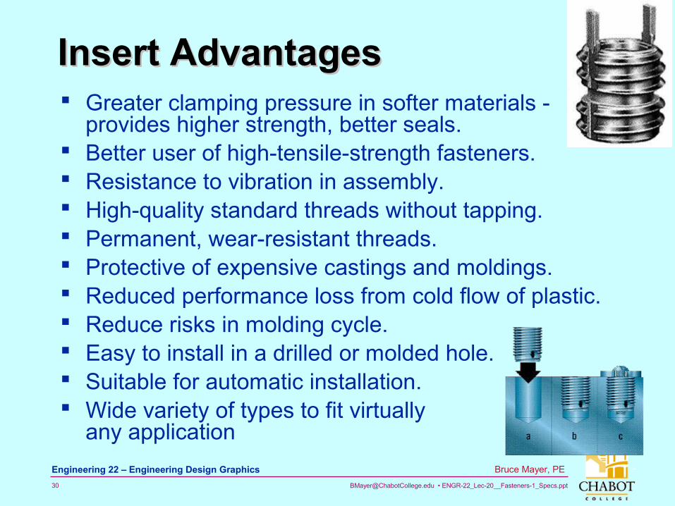
Insert AdvantagesInsert Advantages Greater clamping pressure in softer materials -
provides higher strength, better seals. Better user of high-tensile-strength fasteners. Resistance to vibration in assembly. High-quality standard threads without tapping. Permanent, wear-resistant threads. Protective of expensive castings and moldings. Reduced performance loss from cold flow of plastic. Reduce risks in molding cycle. Easy to install in a drilled or molded hole. Suitable for automatic installation. Wide variety of types to fit virtually
any application
[email protected] • ENGR-22_Lec-20__Fasteners-1_Specs.ppt31
Bruce Mayer, PE Engineering 22 – Engineering Design Graphics
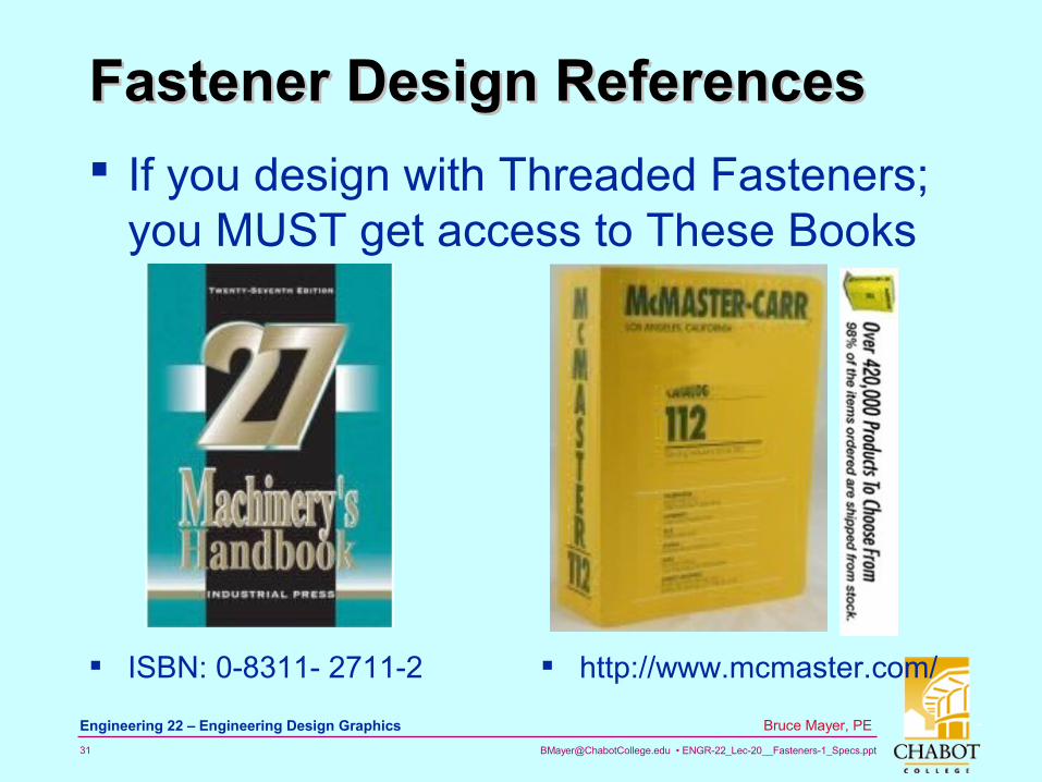
Fastener Design ReferencesFastener Design References
If you design with Threaded Fasteners; you MUST get access to These Books
ISBN: 0-8311- 2711-2 http://www.mcmaster.com/
[email protected] • ENGR-22_Lec-20__Fasteners-1_Specs.ppt32
Bruce Mayer, PE Engineering 22 – Engineering Design Graphics
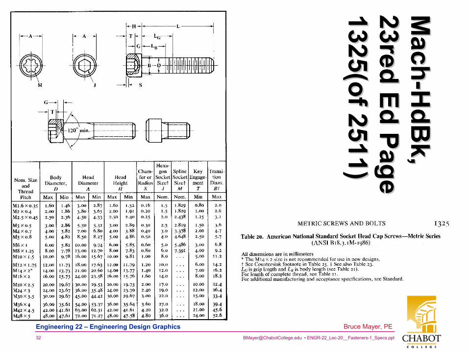
Mach
-Hd
Bk,
Mach
-Hd
Bk,
23red E
d P
age
23red E
d P
age
1325(of 2511)
1325(of 2511)
[email protected] • ENGR-22_Lec-20__Fasteners-1_Specs.ppt33
Bruce Mayer, PE Engineering 22 – Engineering Design Graphics
Wheel ReInventionWheel ReInvention
It has been estimated that CAD-Using Engineers Spend up to 20 Hrs/Month REDRAWING Part for their Designs
Avoid Reinventing the Wheel by• Calling Part Maker and asking for CAD file
• Consult OnLine Parts DataBases
• Consult your Company’s CAD-Block Library
• Ask your Colleagues
• Check AutoCAD Tools
[email protected] • ENGR-22_Lec-20__Fasteners-1_Specs.ppt34
Bruce Mayer, PE Engineering 22 – Engineering Design Graphics
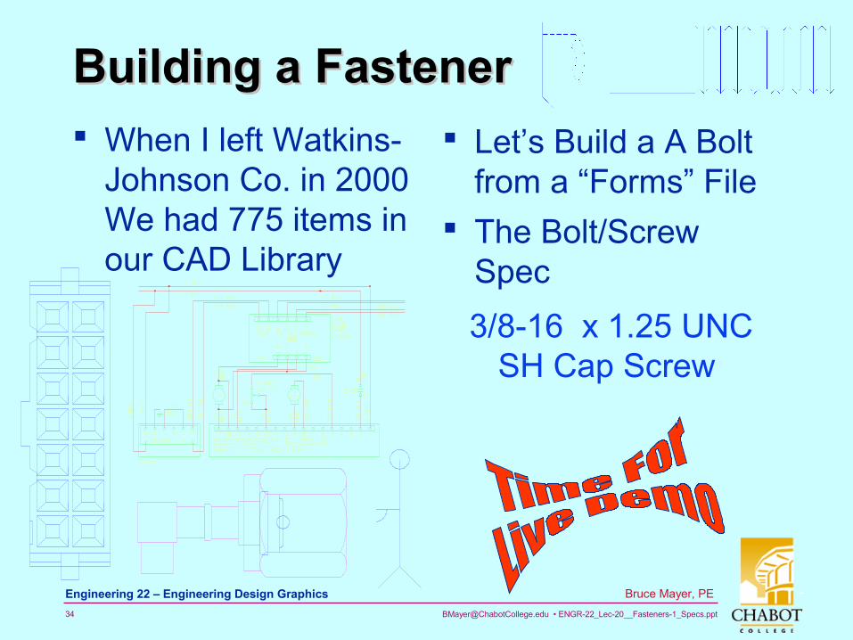
Building a FastenerBuilding a Fastener When I left Watkins-
Johnson Co. in 2000 We had 775 items in our CAD Library
Let’s Build a A Bolt from a “Forms” File
The Bolt/Screw Spec
3/8-16 x 1.25 UNC SH Cap Screw
[email protected] • ENGR-22_Lec-20__Fasteners-1_Specs.ppt35
Bruce Mayer, PE Engineering 22 – Engineering Design Graphics
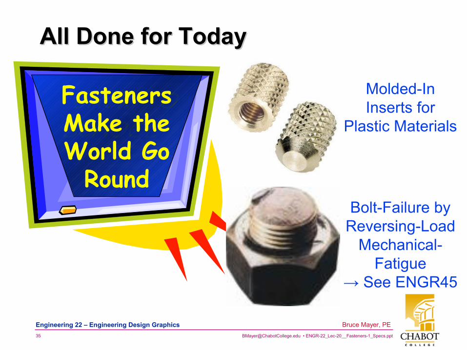
All Done for TodayAll Done for Today
FastenersMake theWorld Go
Round
Molded-In Inserts for
Plastic Materials
Bolt-Failure by Reversing-Load
Mechanical-Fatigue
→ See ENGR45
[email protected] • ENGR-22_Lec-20__Fasteners-1_Specs.ppt36
Bruce Mayer, PE Engineering 22 – Engineering Design Graphics
Bruce Mayer, PELicensed Electrical & Mechanical Engineer
Engr/Math/Physics 25
AppendixAppendix( ) 6972 23 −+−= xxxxf
[email protected] • ENGR-22_Lec-20__Fasteners-1_Specs.ppt37
Bruce Mayer, PE Engineering 22 – Engineering Design Graphics
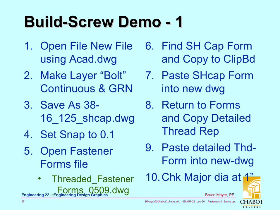
Build-Screw Demo - 1 Build-Screw Demo - 1
1. Open File New File using Acad.dwg
2. Make Layer “Bolt” Continuous & GRN
3. Save As 38-16_125_shcap.dwg
4. Set Snap to 0.1
5. Open Fastener Forms file• Threaded_Fastener
_Forms_0509.dwg
6. Find SH Cap Form and Copy to ClipBd
7. Paste SHcap Form into new dwg
8. Return to Forms and Copy Detailed Thread Rep
9. Paste detailed Thd-Form into new-dwg
10.Chk Major dia at 1”
[email protected] • ENGR-22_Lec-20__Fasteners-1_Specs.ppt38
Bruce Mayer, PE Engineering 22 – Engineering Design Graphics
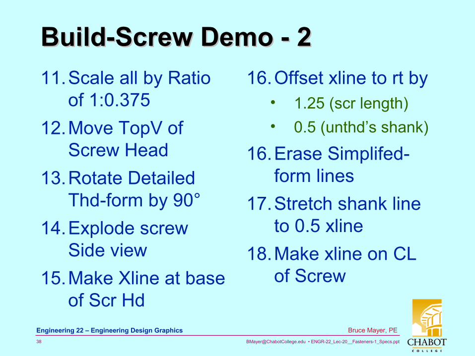
Build-Screw Demo - 2Build-Screw Demo - 2
11.Scale all by Ratio of 1:0.375
12.Move TopV of Screw Head
13.Rotate Detailed Thd-form by 90°
14.Explode screw Side view
15.Make Xline at base of Scr Hd
16.Offset xline to rt by• 1.25 (scr length)
• 0.5 (unthd’s shank)
16.Erase Simplifed-form lines
17.Stretch shank line to 0.5 xline
18.Make xline on CL of Screw
[email protected] • ENGR-22_Lec-20__Fasteners-1_Specs.ppt39
Bruce Mayer, PE Engineering 22 – Engineering Design Graphics
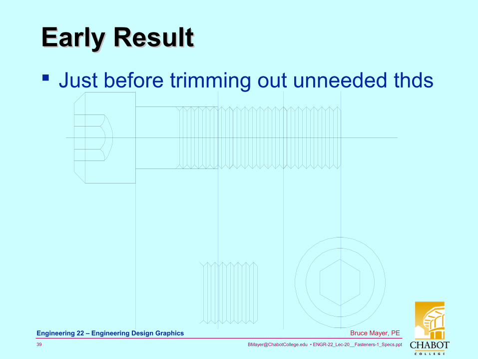
Early ResultEarly Result
Just before trimming out unneeded thds
[email protected] • ENGR-22_Lec-20__Fasteners-1_Specs.ppt40
Bruce Mayer, PE Engineering 22 – Engineering Design Graphics
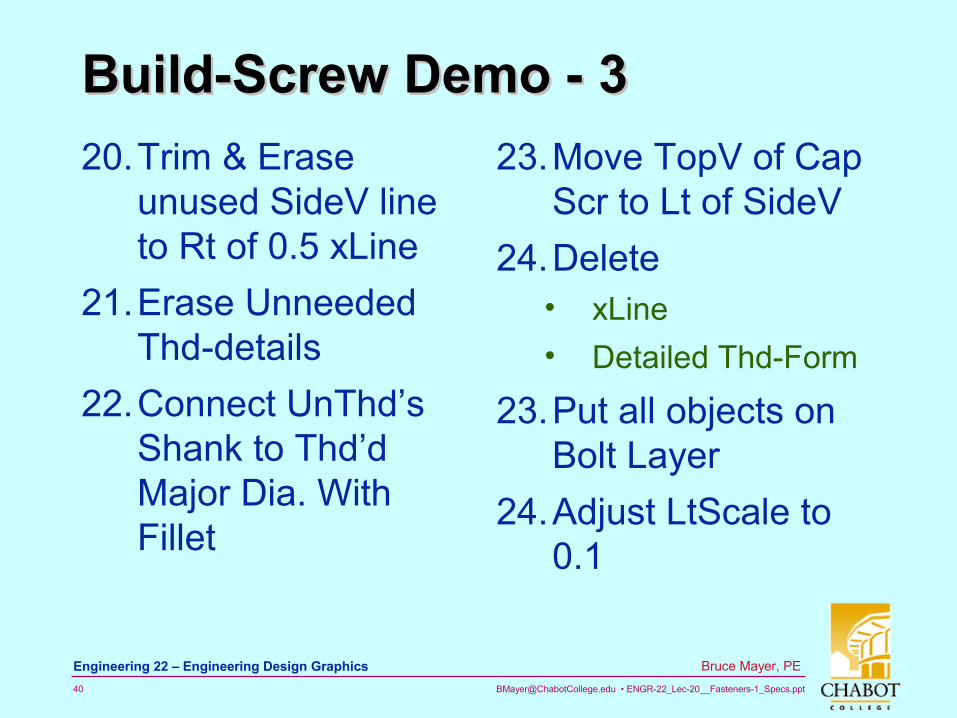
Build-Screw Demo - 3Build-Screw Demo - 3
20.Trim & Erase unused SideV line to Rt of 0.5 xLine
21.Erase Unneeded Thd-details
22.Connect UnThd’s Shank to Thd’d Major Dia. With Fillet
23.Move TopV of Cap Scr to Lt of SideV
24.Delete• xLine
• Detailed Thd-Form
23.Put all objects on Bolt Layer
24.Adjust LtScale to 0.1
[email protected] • ENGR-22_Lec-20__Fasteners-1_Specs.ppt41
Bruce Mayer, PE Engineering 22 – Engineering Design Graphics
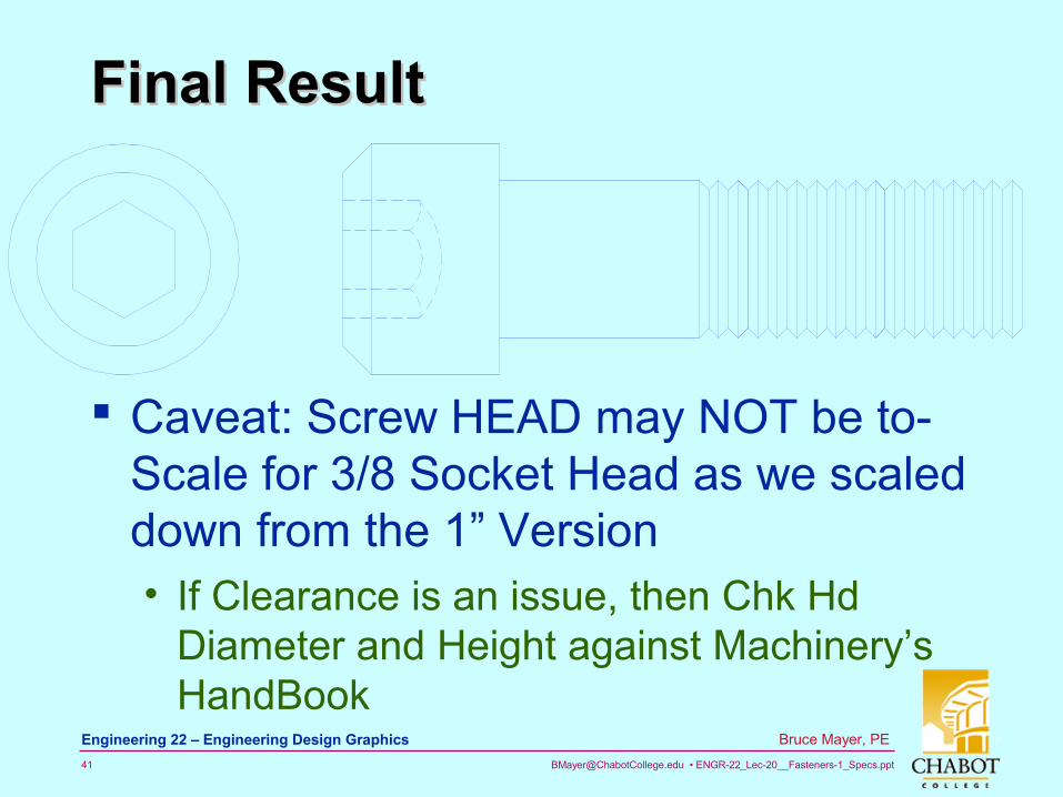
Final ResultFinal Result
Caveat: Screw HEAD may NOT be to-Scale for 3/8 Socket Head as we scaled down from the 1” Version• If Clearance is an issue, then Chk Hd
Diameter and Height against Machinery’s HandBook