Embed Size (px)
Citation preview
THÈSETHÈSEEn vue de l'obtention du
DOCTORAT DE L’UNIVERSITÉ DE TOULOUSEDOCTORAT DE L’UNIVERSITÉ DE TOULOUSE
Délivré par l'Université Toulouse III - Paul Sabatier
Discipline ou spécialité : Informatique
JURYMourad Chabane Oussalah – Professor, Université de Nantes, France (examiner)
Andrea Omicini – Professor, Università di Bologna, Italy (examiner)Jean-Michel Bruel – Professor, Université de Toulouse, France (president)
Tom Holvoet – Professor, Katholieke Univesiteit Leuven, Belgium (member)Marie-Pierre Gleizes – Professor, Université de Toulouse, France (supervisor)
Jean-Paul Arcangeli – Associate Professor, HDR, Université de Toulouse, France (co-supervisor)
Ecole doctorale : Mathématiques Informatique Télécommunications (MITT)Unité de recherche : Institut de Recherche en Informatique de Toulouse (IRIT)
Directeur(s) de Thèse : Marie-Pierre Gleizes and Jean-Paul ArcangeliRapporteurs : Mourad Chabane Oussalah and Andrea Omicini
Présentée et soutenue par Victor Noël
Le July 18th 2012
Titre : Component-based Software Architectures and Multi-Agent Systems:
Mutual and Complementary Contributionsfor Supporting Software Development

THÈSETHÈSEEn vue de l'obtention du
DOCTORAT DE L’UNIVERSITÉ DE TOULOUSEDOCTORAT DE L’UNIVERSITÉ DE TOULOUSE
Délivré par Université Toulouse III - Paul Sabatier
Discipline ou spécialité : Informatique
JURYMourad Chabane Oussalah – Professeur, Université de Nantes, France (rapporteur)
Andrea Omicini – Professeur, Università di Bologna, Italie (rapporteur)Jean-Michel Bruel – Professeur, Université de Toulouse, France (président)
Tom Holvoet – Professeur, Katholieke Univesiteit Leuven, Belgique (membre)Marie-Pierre Gleizes – Professeur, Université de Toulouse, France (directeur)
Jean-Paul Arcangeli – Maître de Conférences, HDR, Université de Toulouse, France (co-directeur)
Ecole doctorale : Mathématiques Informatique Télécommunications (MITT)Unité de recherche : Institut de Recherche en Informatique de Toulouse (IRIT)
Directeur(s) de Thèse : Marie-Pierre Gleizes et Jean-Paul ArcangeliRapporteurs : Mourad Chabane Oussalah et Andrea Omicini
Présentée et soutenue par Victor Noël
Le 18 juillet 2012
Titre : Architectures logicielles à base de composants et systèmes multi-agents :
contributions mutuelles et complémentairespour supporter le développement logiciel

AbstractIn this thesis, we explore the various aspects of the mutual and complementary con-
tributions that multi-agent systems (MASs) and component-based software architectures(CBSAs) can provide to each other. In a way, this work is the study of how both worlds canbe integrated together, either by supporting MAS implementation using component-basedabstractions or by supporting CBSA construction and adaptation using self-adaptive MASs.
As a pragmatic starting point, we study how MAS development is currently done in thefield and propose an understanding of the general methodology of development of MASsfrom an architecturally-oriented point of view. This results in the distinction between twomain activities in MAS development. The first one, which we call macro-level design, isconcerned with requirements and design choices tackled by multi-agent approaches as away to decompose the solution in terms of agents and their interactions. The second one,which we call micro-level design, is concerned with requirements and design choices thataccompany and more importantly support the result of the first activity to bridge the gapbetween design and implementation. From this conclusion, we infer that it is necessary tosupport this micro-level architectural activity with adequate abstractions that favour reuse,separation of concern and maintenance. In particular, an abstraction called “species of agent”is introduced for this purpose. It integrates with traditional component-oriented abstractionsand acts both as an architectural abstraction and as an implementation. We define, illustrate,analyse and discuss a component model (SpeAD), an architectural description language(SpeADL) and a design method (SpEArAF) that ease and guide the description and theimplementation of MASs using species of agents. This complete answer to the question ofMAS development, which is supported by a tool (MAY) to exploit SpeADL with Java, hasbeen applied to many applications in our research team.
Then, by setting back such a solution in the context of the CBSA field, we show how MASsdiffer and relate to traditional means of development in terms of structural abstractions.
To complete this study, we explore through various experiments how self-adaptive MASscan be used to support the building and the adaptation of CBSAs. Here, the agents andtheir continuous reorganisation act on one hand as the engine of the construction and of thedynamic adaptation of the architecture, and on the other hand as the runtime container thatactually connects these elements together and maintains the architecture alive and working.This makes such an approach, even though it is exploratory and prototypal, a completelyintegrated solution to architecture building, execution and adaptation. This work opensseveral interesting research paths to build tools to support the development and the evolutionof software architectures at design and at runtime.
v

Remerciements
Il paraît que l’écriture de cette partie du mémoire de thèse est celle où l’on doit se faire leplus plaisir. Or, ce passage sera certainement le plus lu de ces quelques 200 pages, c’est doncici que la pression est la plus forte.
Je vais d’ailleurs commencer par remercier ceux qui sont à même d’émettre un avis surl’intégralité de mon travail, c’est-à-dire chacun des membres de mon jury de thèse. Mercipour l’investissement que vous avez mis dans l’évaluation de mes écrits et de ma soutenance,je suis très fier d’avoir eu votre approbation et vos noms associés à ma production. Parmiceux-ci, je remercie en particulier ma directrice de thèse, Marie-Pierre, pour m’avoir faitconfiance tout au long de ces quatre années et pour avoir su gérer au mieux mon potentielprocrastinateur. Et puis bien sûr, il y a Jean-Paul, qui a, avant tout, eu la patience de me suivresans faille dans mes délires et élucubrations. Merci pour l’investissement que tu as mis danschacun de nos nombreux échanges, cela m’a à chaque fois permis de faire des bonds en avantdans mon travail de recherche.
D’une façon générale, je ne peux que remercier l’intégralité de l’équipe SMAC quiapplique chaque jour dans la vie réelle les préceptes de coopération utilisés dans leur travauxde recherche. Une aide importante m’a été en particulier apportée par mon pool de cobayesde compét’. Sans vous je n’aurais jamais pu faire de MAY, et tout ce qui se cache derrière, cequ’il est maintenant (mais préparez-vous, la v3 arrive, il va falloir tout reprendre de zéro ! !).De plus, toutes nos discussions autour du développement des SMA m’ont permis d’avoirun minimum de confiance dans la qualité et l’utilité de mon travail. Dans cette équipe, ilest difficile de mettre en place une compartimentation entre collègues et amis, et ces mêmespersonnes m’ont aussi grandement accompagné dans des activités de détente au labo eten dehors. La personne la plus méritante est certainement Jérémy avec qui je partage unbureau depuis plusieurs années et qui me supporte tel un moine zen. Et puis, sans ordreparticulier, nous retrouvons Valérian, François, Luc, Arnaud, Noélie, Nicolas, Sylvain, Önder,Raja, Simon, Julien, Elsy, Zied et autres stagiaires de passage.
Puisque l’on parle de stagiaires, il est nécessaire de souligner le plaisir que j’ai eu àtravailler avec Grégoire. Son travail, complété d’ailleurs par l’aide de Pierre, a énormémentnourri le chapitre 7 de ce mémoire. Ce chapitre contient aussi le résultat d’une collaborationavec l’équipe AgentWise de KULeuven qui a eu la gentillesse de m’accueillir pendant 2 moisdurant ma thèse. En particulier, ces résultats s’appuient sur les travaux de mon ami Marioqui m’a beaucoup apporté, autant sur le plan personnel que professionnel. L’accueil que
vii
m’ont réservé Tom Holvoet et Danny Weyns m’a aussi été très cher et ces personnes ontnourri certaines des réflexions qui sont exposées dans ce mémoire. Mon passage à Leuven amarqué un tournant dans mon travail de recherche et a en particulier orienté mon attentionen direction des architectures logicielles. Un simple merci aussi à Maroussia qui a eu lapatience de passer un certain nombre d’après-midi en ma compagnie pour me guider dansl’implémentation d’un modèle SMA d’écoulement de l’eau :)
Maintenant, passons aux choses sérieuses, ou plutôt, à LA chose sérieuse : Christine !Même si je pars, sachez que vous, votre pancake et le lambda-calcul resterez toujours dansmon cœur ! Plus sérieusement : Christine, Frédéric et Celia, merci pour l’amitié journalièreque nous avons partagée durant nos repas et pauses thé. Et surtout, merci pour les modèlesque vous avez été tout les trois pour moi autant dans l’enseignement que dans la participationà la vie de l’université. C’est grâce à vous que je me suis (un peu) impliqué dans la collectivitéet que je peux me considérer comme ayant une utilité sociale.
Si je sors le nez du boulot, je peux maintenant me tourner vers les nombreux amis quej’ai rencontré à Toulouse. Je ne citerai personne, mais vous vous reconnaîtrez (je suis tropmalin hein, comme ça je n’oublie personne ;). Merci pour votre support mais surtout pourm’avoir permis de faire évoluer ma personnalité pendant 4 ans : je pense qu’avec vous, j’aiautant gagné en expérience personnelle que ce que la thèse a pu m’apporter en expérienceprofessionnelle.
Ma famille, que je n’ai pas beaucoup vu ces quatre dernières années : merci mes parentspour m’avoir fait suffisamment intelligent pour arriver jusque-là sans encombres, merci mespetite et grande sœurs pour m’avoir appris à craindre et à respecter les femmes (oui, cela n’aaucun rapport avec la thèse).
Et puis merci à tout ceux qui sont venus me soutenir lors de ma soutenance (je sais quevous n’êtes là que pour le pot !), amis et famille, ainsi qu’à ceux qui m’ont bien aidé pourl’organisation.
Et enfin, pour conclure, ma seconde famille, qui me supporte et me façonne jour aprèsjour. Timomo, en plus de m’avoir fait rencontrer plein de gens supers, jusqu’ici tu m’as apprispas mal de trucs utiles sur la vie. Jojo, merci encore pour ta gentillesse qui cache une sagacitéet une écoute dont j’ai pu apprécier les bienfaits ces derniers mois, et puis surtout pour tondébit de blagues (drôles) qui est le plus impressionnant jamais entendu ! Et puis il y a Tibtib,la seule personne au monde qui arrive à me suivre jusque dans mes raisonnements les plustordus : merci pour tes cours de piano (et puis pour tout le reste).
viii
Contents
Contents ix
List of Figures xv
List of Tables xvii
Introduction to the Thesis xixMain Motivations . . . . . . . . . . . . . . . . . . . . . . . . . . . . . . . . . . . . . . . xxMain Contributions . . . . . . . . . . . . . . . . . . . . . . . . . . . . . . . . . . . . . . xxPlan of the Thesis . . . . . . . . . . . . . . . . . . . . . . . . . . . . . . . . . . . . . . . xxiScientific Results . . . . . . . . . . . . . . . . . . . . . . . . . . . . . . . . . . . . . . . xxiiiEditorial Notice . . . . . . . . . . . . . . . . . . . . . . . . . . . . . . . . . . . . . . . . xxiv
1 Engineering Software: Software Architectures and Multi-Agent Systems 11.1 Software Engineering . . . . . . . . . . . . . . . . . . . . . . . . . . . . . . . . . . 2
1.1.1 General Terms . . . . . . . . . . . . . . . . . . . . . . . . . . . . . . . . . . 21.1.2 Modelling the Solution . . . . . . . . . . . . . . . . . . . . . . . . . . . . 21.1.3 Methods and Methodologies . . . . . . . . . . . . . . . . . . . . . . . . . 31.1.4 Reuse of Development Artefacts and Tools . . . . . . . . . . . . . . . . . 4
1.2 Software Architectures . . . . . . . . . . . . . . . . . . . . . . . . . . . . . . . . . 41.2.1 Component-Based Software Architectures . . . . . . . . . . . . . . . . . 51.2.2 Design of Software Architecture . . . . . . . . . . . . . . . . . . . . . . . 61.2.3 Capturing Experience . . . . . . . . . . . . . . . . . . . . . . . . . . . . . 8
1.3 Multi-Agent Systems . . . . . . . . . . . . . . . . . . . . . . . . . . . . . . . . . . 91.3.1 Agents . . . . . . . . . . . . . . . . . . . . . . . . . . . . . . . . . . . . . . 91.3.2 Multi-Agent Systems . . . . . . . . . . . . . . . . . . . . . . . . . . . . . . 101.3.3 AMAS: Adaptive Multi-Agent Systems . . . . . . . . . . . . . . . . . . . 111.3.4 Scope . . . . . . . . . . . . . . . . . . . . . . . . . . . . . . . . . . . . . . . 12
1.4 Conclusion . . . . . . . . . . . . . . . . . . . . . . . . . . . . . . . . . . . . . . . . 12
ix
Contents
I Software Architectures for Multi-Agent Systems 15
2 State of the Art on MAS Development 172.1 Characterisation of MAS Meta-Models from an Architectural Viewpoint . . . . 182.2 Walking Through the Different Aspects of MAS Development . . . . . . . . . . 19
2.2.1 The Design Point of View . . . . . . . . . . . . . . . . . . . . . . . . . . . 192.2.2 Diversity of Requirements . . . . . . . . . . . . . . . . . . . . . . . . . . . 222.2.3 Commonality of Requirements and Elements of Solution . . . . . . . . 242.2.4 The Implementation Point of View . . . . . . . . . . . . . . . . . . . . . . 252.2.5 From Design to Implementation . . . . . . . . . . . . . . . . . . . . . . . 282.2.6 Practical Observations . . . . . . . . . . . . . . . . . . . . . . . . . . . . . 29
2.3 Analysis: Should We Tweak or Build?! . . . . . . . . . . . . . . . . . . . . . . . . 302.3.1 The Gap, Again . . . . . . . . . . . . . . . . . . . . . . . . . . . . . . . . . 312.3.2 Types of Agents and Adequate Abstractions . . . . . . . . . . . . . . . . 332.3.3 Two Levels of Architectural Design . . . . . . . . . . . . . . . . . . . . . 342.3.4 Evidences from the Literature . . . . . . . . . . . . . . . . . . . . . . . . 342.3.5 Existing Answers . . . . . . . . . . . . . . . . . . . . . . . . . . . . . . . . 362.3.6 Revisiting the Different Works . . . . . . . . . . . . . . . . . . . . . . . . 37
2.4 Challenges: Meta Micro-Level Design . . . . . . . . . . . . . . . . . . . . . . . . 39
3 Dedicated Micro-Level Software Architectures for MAS Development 433.1 Characterizing MAS Development: Architecture-Centric Methodology . . . . . 45
3.1.1 Multi-Level Architectural Design . . . . . . . . . . . . . . . . . . . . . . . 453.1.2 Operative and Business Concerns . . . . . . . . . . . . . . . . . . . . . . 483.1.3 Implementation . . . . . . . . . . . . . . . . . . . . . . . . . . . . . . . . . 493.1.4 Illustrating the Methodology . . . . . . . . . . . . . . . . . . . . . . . . . 503.1.5 Conclusion on the Methodology . . . . . . . . . . . . . . . . . . . . . . . 53
3.2 Component-Based Micro-Level Architectures . . . . . . . . . . . . . . . . . . . . 543.2.1 The SpeAD− Base Component Model . . . . . . . . . . . . . . . . . . . . 553.2.2 The SpeAD Component Model . . . . . . . . . . . . . . . . . . . . . . . . 61
3.3 Capturing Reusable Experience . . . . . . . . . . . . . . . . . . . . . . . . . . . . 683.3.1 What and How . . . . . . . . . . . . . . . . . . . . . . . . . . . . . . . . . 683.3.2 Components Library . . . . . . . . . . . . . . . . . . . . . . . . . . . . . . 70
3.4 The SpEArAF Method . . . . . . . . . . . . . . . . . . . . . . . . . . . . . . . . . 823.4.1 Component-Based Architectures for MASs . . . . . . . . . . . . . . . . . 853.4.2 Iterative and Incremental Micro-Architectural Design . . . . . . . . . . . 853.4.3 Additional Guidelines . . . . . . . . . . . . . . . . . . . . . . . . . . . . . 87
3.5 Conclusion . . . . . . . . . . . . . . . . . . . . . . . . . . . . . . . . . . . . . . . . 88
4 Application 914.1 Context and Requirements . . . . . . . . . . . . . . . . . . . . . . . . . . . . . . . 92
4.1.1 Environment of the System . . . . . . . . . . . . . . . . . . . . . . . . . . 92
x
Contents
4.1.2 Functional and Non-Functional Requirements for the VGD . . . . . . . 934.1.3 Non-Functional Requirements for the Development . . . . . . . . . . . . 94
4.2 Macro-level Architectural Design . . . . . . . . . . . . . . . . . . . . . . . . . . . 944.2.1 Macro-Level Requirements Extraction . . . . . . . . . . . . . . . . . . . . 954.2.2 Problem Domain Model . . . . . . . . . . . . . . . . . . . . . . . . . . . . 954.2.3 Temporal Interactions of the VGD with its Environment . . . . . . . . . 964.2.4 Multi-Agent System . . . . . . . . . . . . . . . . . . . . . . . . . . . . . . 96
4.3 Micro-Level Requirements Extraction . . . . . . . . . . . . . . . . . . . . . . . . 984.3.1 Assumptions Made during the Design . . . . . . . . . . . . . . . . . . . 984.3.2 Supplementary Design Choices . . . . . . . . . . . . . . . . . . . . . . . . 98
4.4 Micro-Level Architectural Design . . . . . . . . . . . . . . . . . . . . . . . . . . . 994.4.1 Operative Requirements . . . . . . . . . . . . . . . . . . . . . . . . . . . . 994.4.2 Business Requirements . . . . . . . . . . . . . . . . . . . . . . . . . . . . 1004.4.3 Incremental Design . . . . . . . . . . . . . . . . . . . . . . . . . . . . . . . 1004.4.4 Complete Design and Implementation . . . . . . . . . . . . . . . . . . . 106
4.5 Conclusion . . . . . . . . . . . . . . . . . . . . . . . . . . . . . . . . . . . . . . . . 106
5 Positioning, Analysis and Experimental Feedbacks 1095.1 Positioning the Contribution . . . . . . . . . . . . . . . . . . . . . . . . . . . . . 1095.2 Analysis . . . . . . . . . . . . . . . . . . . . . . . . . . . . . . . . . . . . . . . . . 110
5.2.1 Architectural Abstraction . . . . . . . . . . . . . . . . . . . . . . . . . . . 1115.2.2 Implementation Abstraction . . . . . . . . . . . . . . . . . . . . . . . . . 1125.2.3 Why and When to Use SpeAD . . . . . . . . . . . . . . . . . . . . . . . . 112
5.3 Experimental Applications and Users Feedbacks . . . . . . . . . . . . . . . . . . 1135.4 Conclusion . . . . . . . . . . . . . . . . . . . . . . . . . . . . . . . . . . . . . . . . 115
II Integrating Multi-Agent Systems and Software Architectures 117
6 MASs and CBSAs Side by Side: Component-based Component Containers 1196.1 Related Works in the Software Architecture Field . . . . . . . . . . . . . . . . . 120
6.1.1 Reusing High-Level Design . . . . . . . . . . . . . . . . . . . . . . . . . . 1206.1.2 Dynamic Component Creation and Connection . . . . . . . . . . . . . . 122
6.2 Relations between Component-based Architectural Concepts . . . . . . . . . . 1236.3 Defining and Using Dedicated Component Models and Containers . . . . . . . 125
6.3.1 Defining the Component Model . . . . . . . . . . . . . . . . . . . . . . . 1256.3.2 Defining the Component Container . . . . . . . . . . . . . . . . . . . . . 1266.3.3 Implementing the Component Container . . . . . . . . . . . . . . . . . . 1266.3.4 Using the Component Container . . . . . . . . . . . . . . . . . . . . . . . 1276.3.5 Going Further . . . . . . . . . . . . . . . . . . . . . . . . . . . . . . . . . . 127
6.4 Building Dedicated Component-Based Component Containers . . . . . . . . . 1276.5 Revisiting MASs Design as a Family of Paradigms . . . . . . . . . . . . . . . . . 129
xi
Contents
6.6 Horizontally Integrating CBSAs, MASs and Other Paradigms . . . . . . . . . . 130
7 From Self-Composing Components to Self-Designing Software Architectures 1337.1 MASs for Self-Adaptive Software Architectures . . . . . . . . . . . . . . . . . . 134
7.1.1 Why MAS . . . . . . . . . . . . . . . . . . . . . . . . . . . . . . . . . . . . 1347.1.2 MAS-based Containers . . . . . . . . . . . . . . . . . . . . . . . . . . . . 135
7.2 The CASAS Experiment: Non-Functional Adaptation . . . . . . . . . . . . . . . 1367.2.1 Scenario . . . . . . . . . . . . . . . . . . . . . . . . . . . . . . . . . . . . . 1377.2.2 The Macodo Organisation Model . . . . . . . . . . . . . . . . . . . . . . 1397.2.3 Mapping Macodo Organisations to Composite Services in BPEL . . . . 1407.2.4 Defining the CASAS Component Model . . . . . . . . . . . . . . . . . . 1417.2.5 Multi-Agent System . . . . . . . . . . . . . . . . . . . . . . . . . . . . . . 1427.2.6 Defining the CASAS Component Container . . . . . . . . . . . . . . . . 1437.2.7 Implementation of the CASAS Component Container . . . . . . . . . . 1437.2.8 Using the CASAS Component Container . . . . . . . . . . . . . . . . . . 1447.2.9 Discussion and Possible Evolutions . . . . . . . . . . . . . . . . . . . . . 144
7.3 The Greg Experiment: Opportunistic Composition . . . . . . . . . . . . . . . . 1457.3.1 Motivating Scenario . . . . . . . . . . . . . . . . . . . . . . . . . . . . . . 1467.3.2 Modelling the Problem Domain . . . . . . . . . . . . . . . . . . . . . . . 1467.3.3 Defining the Greg Component Model . . . . . . . . . . . . . . . . . . . . 1477.3.4 Defining the Greg Component Container . . . . . . . . . . . . . . . . . . 1517.3.5 Implementation of the Greg Component Container . . . . . . . . . . . . 1527.3.6 Use of the Greg Component Container . . . . . . . . . . . . . . . . . . . 1527.3.7 Discussion and Possible Evolutions . . . . . . . . . . . . . . . . . . . . . 152
7.4 Discussion: MASs for CBSAs . . . . . . . . . . . . . . . . . . . . . . . . . . . . . 1537.4.1 Adaptation and Emergence . . . . . . . . . . . . . . . . . . . . . . . . . . 1537.4.2 Component Models and Containers . . . . . . . . . . . . . . . . . . . . . 1547.4.3 Better Adaptation for CBSAs . . . . . . . . . . . . . . . . . . . . . . . . . 155
7.5 Towards Human-Assisted Self-Designing Software Architectures . . . . . . . . 1557.5.1 Styles and Patterns that Emerge . . . . . . . . . . . . . . . . . . . . . . . 1557.5.2 Generalisation to Architectural Views . . . . . . . . . . . . . . . . . . . . 156
Back 159
8 Conclusions and Perspectives 1618.1 Contributions of the Thesis . . . . . . . . . . . . . . . . . . . . . . . . . . . . . . 161
8.1.1 Software Architectures for Multi-Agent Systems . . . . . . . . . . . . . . 1618.1.2 Component-Based Software Architectures . . . . . . . . . . . . . . . . . 1628.1.3 Multi-Agent Systems and Component-Based Software Architectures
Side by Side . . . . . . . . . . . . . . . . . . . . . . . . . . . . . . . . . . . 1638.1.4 Multi-Agent Systems for Software Architectures . . . . . . . . . . . . . . 163
xii
Contents
8.2 Open Problems and Perspectives . . . . . . . . . . . . . . . . . . . . . . . . . . . 1648.2.1 Methodological Perspectives . . . . . . . . . . . . . . . . . . . . . . . . . 1648.2.2 Architectural Perspectives . . . . . . . . . . . . . . . . . . . . . . . . . . . 1658.2.3 Evaluation Perspectives . . . . . . . . . . . . . . . . . . . . . . . . . . . . 165
A Design and Implementation MAS Meta-Models 167A.1 Agent and MAS Meta-Models . . . . . . . . . . . . . . . . . . . . . . . . . . . . . 167A.2 Development Support Meta-Models . . . . . . . . . . . . . . . . . . . . . . . . . 170
A.2.1 Languages . . . . . . . . . . . . . . . . . . . . . . . . . . . . . . . . . . . . 170A.2.2 Frameworks and Platforms . . . . . . . . . . . . . . . . . . . . . . . . . . 170
B Implementation of SpeAD: Make Agents Yourself 175B.1 Make Agents Yourself . . . . . . . . . . . . . . . . . . . . . . . . . . . . . . . . 175B.2 From SpeADL to Java . . . . . . . . . . . . . . . . . . . . . . . . . . . . . . . . . 176
Author’s Bibliography 179
Bibliography 181
xiii

List of Figures
2.1 Activities in MASs development . . . . . . . . . . . . . . . . . . . . . . . . . . . . . 35
3.1 Abstract process followed by MAS development in general, described using SPEM 463.2 Different sources for requirements . . . . . . . . . . . . . . . . . . . . . . . . . . . . 473.3 Different types of micro-level requirements . . . . . . . . . . . . . . . . . . . . . . . 493.4 Meta-model of the SpeAD− component model . . . . . . . . . . . . . . . . . . . . . 553.5 Components descriptions in SpeADL− and interfaces description in Java . . . . . 563.6 Component specialization in SpeADL− . . . . . . . . . . . . . . . . . . . . . . . . . 583.7 Component implementations in Java . . . . . . . . . . . . . . . . . . . . . . . . . . . 593.8 Component implementation in Java with parts . . . . . . . . . . . . . . . . . . . . . 603.9 Component instantiation and usage . . . . . . . . . . . . . . . . . . . . . . . . . . . 603.10 Meta-model of the SpeAD component model . . . . . . . . . . . . . . . . . . . . . . 613.11 Ecosystem description for an interconnection mechanism in SpeADL . . . . . . . . 633.12 Ecosystem description for a simple MAS in SpeADL . . . . . . . . . . . . . . . . . 643.13 Ecosystem implementation in Java for an interconnection mechanism . . . . . . . 653.14 Ecosystem implementation in Java . . . . . . . . . . . . . . . . . . . . . . . . . . . . 673.15 Interfaces descriptions in Java . . . . . . . . . . . . . . . . . . . . . . . . . . . . . . . 713.16 Sequential dispatcher description in SpeADL . . . . . . . . . . . . . . . . . . . . . . 733.17 Sequential dispatcher implementation in Java . . . . . . . . . . . . . . . . . . . . . 733.18 Forward component . . . . . . . . . . . . . . . . . . . . . . . . . . . . . . . . . . . . 743.19 Direct references mechanism description in SpeADL . . . . . . . . . . . . . . . . . 753.20 Direct references mechanism implementation in Java . . . . . . . . . . . . . . . . . 763.21 Interconnection mechanisms descriptions in SpeADL . . . . . . . . . . . . . . . . . 773.22 The ReliableObserve and Observe interfaces in Java . . . . . . . . . . . . . . . . . 773.23 Value Publishing interconnection mechanism implementation in Java . . . . . . . 783.24 An ecosystem for agents referenced by names and observing each other values in
SpeADL . . . . . . . . . . . . . . . . . . . . . . . . . . . . . . . . . . . . . . . . . . . . 793.25 The NamedPublishMASFactory interface in Java . . . . . . . . . . . . . . . . . . . . . 803.26 Implementation of NamedPublishMAS and one of the behaviour class in Java . . . . 813.27 Use of NamedPublishMAS in Java . . . . . . . . . . . . . . . . . . . . . . . . . . . . . 823.28 Template of an AMAS agent architecture in SpeADL . . . . . . . . . . . . . . . . . 833.29 Implementation of the template for an AMAS agent architecture in Java . . . . . . 84
xv
List of Figures
3.30 The Species to Engineer Architectures for Agent Frameworks (SpEArAF) Method. 86
4.1 Use Cases for the VGD in UML . . . . . . . . . . . . . . . . . . . . . . . . . . . . . . 934.2 Sequences diagram for the VGD and its environment interactions in UML . . . . 964.3 Micro-architecture, Cycle 1: Constraint Agents Internal Architecture . . . . . . . . 1014.4 Micro-architecture, Cycle 1: MAS Ecosystem . . . . . . . . . . . . . . . . . . . . . . 1034.5 Clock component and its specialisation in SpeADL . . . . . . . . . . . . . . . . . . 1044.6 Micro-architecture, Cycle 1: Common Scheduling Ecosystem . . . . . . . . . . . . 1044.7 Micro-architecture, Step 1, Ecosystem Cycle: Scenario Manager Ecosystem . . . . 1054.8 Micro-architecture, Cycle 2: Scenario Manager Ecosystem . . . . . . . . . . . . . . 106
6.1 Relations between frameworks, components models, architectures, components,architectural patterns, architectural styles and paradigms . . . . . . . . . . . . . . . 124
6.2 Interaction mechanisms definition in SpeADL . . . . . . . . . . . . . . . . . . . . . 128
7.1 Transportation plan deployed in a BPEL engine . . . . . . . . . . . . . . . . . . . . 1387.2 Domain Model of the Macodo Context-Driven Organisational Model (Weyns,
Haesevoets, and Helleboogh 2010) . . . . . . . . . . . . . . . . . . . . . . . . . . . . 1397.3 Conceptual solution integrating Macodo organisations, BPEL, and agents . . . . . 1427.4 Composition example . . . . . . . . . . . . . . . . . . . . . . . . . . . . . . . . . . . 147
B.1 MAY in Eclipse . . . . . . . . . . . . . . . . . . . . . . . . . . . . . . . . . . . . . . . 176B.2 Component description for a component named EcosystemX in SpeADL . . . . . . 176B.3 Generated classes from SpeADL to Java for a component named EcosystemX in
UML2 . . . . . . . . . . . . . . . . . . . . . . . . . . . . . . . . . . . . . . . . . . . . . 177
xvi
List of Tables
2.1 Characterisation of Design Models in terms of available Features of ArchitecturalElements . . . . . . . . . . . . . . . . . . . . . . . . . . . . . . . . . . . . . . . . . . . 20
2.2 Classification of Development Supports in terms of available Features of Architec-tural Elements . . . . . . . . . . . . . . . . . . . . . . . . . . . . . . . . . . . . . . . . 26
2.3 Research Works Organised Following the Proposed Classification . . . . . . . . . . 38
5.1 Contributions positioned in the proposed classification . . . . . . . . . . . . . . . . 110
6.1 Mapping between frameworks and partially abstract architectures concepts . . . . 121
7.1 Mapping between web-services and Macodo concepts . . . . . . . . . . . . . . . . 141
xvii

Introduction to the Thesis
This thesis recounts the result of my Ph.D. studies on the synergy between Multi-AgentSystems (MASs) and Software Architectures. I spent this time in the SMAC (Systèmes Multi-Agents Coopératifs) research team of the University of Toulouse under the supervision ofMarie-Pierre Gleizes and Jean-Paul Arcangeli.
In the SMAC team, researchers, among other things, investigate an approach to softwareengineering called Multi-Agent Systems. This approach and the way it is promoted by peoplehere, under the name of Adaptive Multi-Agent Systems (AMAS), is particularly directedat modelling complex systems and solving complex problems. It is characterised by thebuilding of self-adaptive systems whose global behaviour emerges from the behaviours andinteractions of the agents that compose it. In exchange of this “collective intelligence”, itbecomes difficult to prove the correctness of such systems and the best way of verifying thatthey work is through experimental evaluations. It thus becomes important to guarantee thequality of the development process that is followed to produce such software in order tohave meaningful evaluations. In this context, I participated in a topic of research focused onproducing tools, models, methods and development supports useful to support the designand the implementation of such systems.
As far as software engineering is concerned, one important mean of succeeding in theproduction of a software system is by using software architectures. Software architecturespromote a set of practices for organising the development and producing the documen-tation of software systems from design to deployment, but more pragmatically, they arealso instantiated with Component-Based Software Architectures (CBSAs), an approach thattackles the question of considering software architectures only as a composition of softwarecomponents. This is why the initial objective of this Ph.D. was to contribute to the field ofMAS development in order to support the transition between design and implementation byexploiting software architectures. And the more I progressed in my research, and the moreI became convinced of the importance of using such a complete approach for design andimplementation in the context of MASs.
Inversely, being myself before and everything an advocate of traditional and provablesoftware engineering techniques, the more I participated in and studied the building ofself-adaptive MASs, the more I became convinced that such an approach will be a keyelement of the future of software computing. This gave me even more incentive to improvethe quality, productivity and maintainability of the development of MAS-based products. But
xix
Introduction to the Thesis
more importantly, this brought me to investigate how it is possible to build a conceptualbridge between MASs and software architectures, and how MASs can support the design, theadaptation and the evolution of software architectures.
Thus, the ultimate objective of this work is to see how these two ways of making softwarecan complement and mutually support each other. My desire is to be able to integrate the twoby providing an understanding of what links them together and by providing abstractionsthat make it possible in practice.
This thesis is organised into two parts, each tackling an aspect of the synergy betweenMASs and software architectures, namely the exploitation of software architectures to supportMASs development and the integration of MASs and software architectures. Before presentingthe different chapters of these two parts, I present the main motivations and the maincontributions of this thesis.
Main Motivations
The first motivation for this thesis is to ease the development of MASs by improving thequality and productivity of the software process. The idea being that as MAS design is acomplex activity, people that practice it should have their life simplified as much as possiblein order for them to focus on their high-level concerns without bothering with low-level andtechnical problems. This separation of concerns is important so that MAS development canbe more productive but also to obtain an organisation of the development that can be of abetter quality.
Strongly linked to that point, the second motivation for this work is to improve the qualityand the maintainability of MASs themselves as software products. Indeed, in order to be ableto validate correctly the results obtained with MASs, it is necessary to be certain that theirimplementation actually realises what their design describes. The maintenance and evolutionof such software products must also be eased.
A third and last motivation for this thesis is more theoretical and exploratory and isconcerned with the understanding of the links between MASs and software architectures,with a focus on Component-Based Software Architectures. On top of the fact it appeared asan interesting subject of discussions during my researches, a farther reached incentive is tostudy how self-adaptive MASs can provide more adaptivity to software architecture, in theirexecution but also in their development.
Main Contributions
An analysis of current practices in MAS development pointed up a particularity inthe general methodology of MAS development. For MAS, development mainly relies ondevelopment supports that are not adapted to the need of the people that build MASs. Theyare not adapted because every application of MASs has its own specificities, which are not
xx
Plan of the Thesis
adequately answered by the tools available. There is thus a need to build an architecturededicated to the development.
Then, an answer to this need is given in the form of a component-based architecturalapproach to MAS development. This approach emphasises on the different roles in MASdevelopment and gives a focus on software quality, productivity, reusability, maintainabilityand other properties of software architecture practices. In particular, I propose a componentmodel that can be used to support the implementation of MASs in practice by following thisapproach. This model is supported by an iterative and incremental development process anda tool for describing the architectures and implementing them in Java.
Finally, with this contribution as a starting point, I come back to works in the field ofsoftware architectures in order to establish our vision of the relations that exist betweenarchitectural concepts and MASs. On one hand, I show how our component model can beexploited to use MASs side by side with CBSAs, and on the other hand, I also show howMASs can be used to make software architectures more adaptive.
Plan of the Thesis
Chapter 1 introduces the scientific context both parts of this thesis rely on. It containsan understanding of software engineering, software architectures and MASs that I shapedduring my research. It also serves as an introduction to the motivation for the rest of thethesis.
Then this thesis is divided in two parts.
Software Architectures for Multi-Agent Systems. The hypothesis I make in this part ofthe thesis is that all the matters that are tackled in the field of software architectures alsoexist while developing MAS-based applications and thus, must be dealt with. In this context,the motivation of this work is to help the development and find ways to improve thequality, maintainability, reusability of produced software. The content of this part is inthe continuation of previous works of the SMAC research team (Leriche 2006; Leriche andArcangeli 2010).
Chapter 2 looks at existing means of development in the MAS field. It analyses them,extracts and identifies shortcomings of current practices by proposing a classification ofresearch works in the MAS field. It proposes a set of methodological and technical challengesto overcome in order to improve MAS development. This chapter is also the result of studyingMASs produced in the SMAC team and participating in its research work.
Chapter 3 presents a coherent set of solutions to the previously identified challenges:
– A general methodology of MAS development
– A component model with abstractions adapted to the technical challenges
– A development method to exploit in practice the component model within the scope ofthe methodology
xxi
Introduction to the Thesis
– A tool that implements the component model
This chapter is the result of applying the various intermediate versions of the contribution inthe SMAC team and in the UPETEC 1 start-up company, which is a company that applies theresearch results of the team for the industry.
Chapter 4 applies the contribution to a real MAS developed by researchers of the SMACteam in the context of a research project. It concludes with some remarks on what wouldhave happened if the contribution had not been used.
Chapter 5 concludes this part by presenting an analysis of the contribution. It positionsit in the classification defined Chapter 2 and comes back on the identified challenges tohighlight the advantages of its use. It also presents all the academic and industrial works thatexploited the contribution and accompanies them with experimental feedbacks from theirauthors.
Integrating Multi-Agent Systems and Software Architectures. In this part, I am analysingthe proposed contribution from the point of view of the software component and softwarearchitecture field. In this context the motivation of this work is to see how MASs relateto concepts manipulated in the software architecture field and what role they can play intheir dynamic adaptation and construction, in particular for Component-Based SoftwareArchitectures (CBSAs). This part is mostly exploratory and contains a lot of ideas I thinkworth spreading even though they may lake maturity for being published as such. I considerthis part as a research agenda from which different exploration paths can be deepened.
Chapter 6 starts from the contribution and positions it with respect to the main conceptsused for design in the CBSA field. It shows how the contribution can be re-understood inorder to define and build dedicated component-based component models and containers.This actually gives me the possibility to reconsider MAS design and programming into thisbroader frame. I conclude by advocating for the use side to side of MASs and CBSAs as amean to design software using adequate abstractions.
Chapter 7 takes a more dynamic and runtime stance. It first justifies the use of MASs asthe engine of adaptation of software systems. Then, it proposes, through the study of twoexamples of self-adapting software architectures, an analysis of the role that MASs plays in it.
One of these examples is the result of a collaboration with the AgentWise research team,which I present next section, on the adaptation of composite web-services. The secondexample is the result of a Research Master internship on the opportunistic self-compositionof components in ambient context using the AMAS approach we promote in the team.
As a conclusion, I advocate for an integrated and self-organising design, construction andruntime adaptation of software architectures. I present my vision of a MAS-based tool thathelps to organise the development of software architectures, that supports design decisionmaking and software evolution, and that makes the bridge with the running system.
1. UPETEC (Emergence Technology for Unsolved Problems): http://www.upetec.fr/
xxii
Scientific Results
Scientific Results
During my Ph.D., I had the opportunity to produce various scientific results and toparticipate in academic collaborations that are summarised here.
Publications and Collaborations. Since my research subject is in-between two differentfields of computer science, namely MASs and Software Architectures, I had the opportunityto present my works to both communities.
In the beginning of my Ph.D., I published a poster in a French-speaking annual eventon software engineering (Noël et al. 2009) to present the objectives of my work. In parallel,the results of my research Master thesis, that has no link with this thesis, were presented atLNMPR (“Logic Programming and Nonmonotonic Reasoning”), an international conference onlogic programming (Noël and Kakas 2009).
I presented the first version of the contribution of this thesis at AT2AI (“From AgentTheory to Agent Implementation”), an international symposium dedicated to the development ofagent-based systems (Noël, Arcangeli, and Gleizes 2010a). It evolved and was then presentedat EUMAS (“European Workshop on Multi-Agent Systems”), the main European workshop onMASs (Noël, Arcangeli, and Gleizes 2010b).
Then I presented a more mature version of the contribution at CAL (“Conférence francophonesur les Architectures Logicielles”), the main French-speaking conference on software architectures(Noël and Arcangeli 2011). An extended and improved version of the article, and thus the mostmature published results of my thesis, appeared in RNTI (“Revue des Nouvelles Technologies del’Information”), a French journal (Noël, Arcangeli, and Gleizes 2012).
During my Ph.D., I visited the AgentWise research team. AgentWise, headed by TomHolvoet, is part of the DistriNet research group of the Computer Science Department of theUniversity of Leuven in Belgium.
I spent two months with them to work with Mario Henrique Cruz Torres, a Ph.D. there.The result of this work is detailed Chapter 7 and was presented at EUMAS (Cruz Torres et al.2010a), then at MONA+ (“International Workshop Series on Monitoring, Adaptation and Beyond”),an International workshop of the web-service community (Cruz Torres et al. 2010b). I alsointeracted with Tom Holvoet and Danny Weyns, two leading European figures on the matterof, among other things, the relations between MASs and software architectures.
I participated in the regional research project ROSACE 2. I first worked on adaptivecommunication where I took part in the redaction of a book chapter (Lacouture, Rodriguez,et al. 2011). Then I worked on cooperative self-organisation where we used my contributionto develop a prototype of self-organising robots that self-allocate tasks (Georgé et al. 2010;Lacouture, Noël, et al. 2011).
2. ROSACE (Robots and Embedded Self-Adaptive Communicating Systems): http://www.irit.fr/Rosace,737, funded by the RTRA STAE (Fondation de coopération scientifique, Sciences et Technologies pourl’Aéronautique et l’Espace)
xxiii
Introduction to the Thesis
I also participated in the research project AmIE 3 on ambient intelligence and systems. Inthis context, Jean-Paul Arcangeli and I supervised the internship of a Master student thatwas presented at UBIMOB (“Journées Francophones Mobilité et Ubiquité”), a French-speakingannual event on ubiquity and mobility (Denis et al. 2012). The result of this work is detailedChapter 7.
Software. The contribution, in particular the component model I propose in this thesis, hasbeen implemented and is presented Appendix B. This tool is named MAY (Make Agents
Yourself) and is released under the GNU General Public License (GPL). It is incorporated inthe Eclipse IDE (Integrated Development Environment) and provides an editor to describecomponents and architectures conform to the component model. It generate Java code usableto implement the components in a flexible and typesafe way. It comes together with a libraryof reusable components released under the GNU Lesser General Public License (LGPL). Thewebsite of MAY 4 contains tutorials for installing the tool and using the component library.
Teaching. In my last year of Ph.D., I had the opportunity to present the knowledge Igathered on the design and documentation of software architectures to Master students. Itresulted in a 2 hours lecture and a 4 hours tutorial for 60 students. Moreover, MAY, theimplementation of the component model, was used to conduct 8 hours of practical tutorialsto introduce component-based programming to the same students. The teaching material, inFrench, that was given to the students can be found on my personal homepage 5.
Editorial Notice
Even though this thesis is the result of my own work, some parts of it could not have beendone without the help of a lot of people. Thus, in the rest of my thesis, even though I takeresponsibility for everything written in it, I switch to a “royal we” to not have to constantlychoose between pronouns, which eases the flow of the discourse.
In order to ease the reading, every chapter ends with a summary of my contributions.
3. AmIE (Ambient Intelligent Entities): http://www.irit.fr/AmIE,1003, funded by a scientific program ofthe University of Toulouse III (Université Paul Sabatier)
4. http://www.irit.fr/MAY5. http://www.irit.fr/~Victor.Noel/
xxiv
CHAPTER 1Engineering Software: Software
Architectures and Multi-AgentSystems
And (repeat after me) we all promise tostop using the phrase “detailed design”.Try “nonarchitectural design” instead.
Paul ClementsClements et al. (2003)
In this chapter, we introduce background concepts and definitions that are employed inthe thesis. The objective is to get a clear picture of the context into which our contributionfits, but also to present works that influenced it.
It starts with a part on software engineering in general as we understand it. Then, wedevelop the different aspects of the field of software architecture as a mean to do softwareengineering. Finally, we present Multi-Agent Systems (MASs), also as a mean to producesoftware.
Software architectures and MASs are two ways of producing software but each tackledifferent aspects of it. In this sense they are non-competing and non-conflicting. One of theincentives for this thesis is to study how they can be combined together and what advantagesthey can bring to each other. More particularly, the motivations are, for the first part ofthis thesis, how software architectures can support the development of MASs and, for thesecond part, what are the links between MASs and software architectures and how MASscan help to make software architectures more “intelligent”. In both parts, the focus is put onhow practically these questions can be answered using adequate abstractions for design andimplementation.
1
1. Engineering Software: Software Architectures and Multi-Agent Systems
1.1 Software Engineering
In the field of software engineering, the objective of development could be summarised asproducing a software solution to a problem. This definition contains three important concepts:the problem, the solution and the process. We now detail these concepts and what evolvearound them during software development.
This section mostly contains definitions that are important from our point of view and,even though they can be considered as subjective, they only act as a set of concepts needed toshare a common language for the rest of this thesis, without being axioms or hypothesis.
1.1.1 General Terms
The development starts with a problem to solve. There exists several ways of expressingthe problem, we will see the most well-known one Section 1.2. The solution is the result ofanswering the problem. A software solution, that we also sometimes call the application orthe system, is the main artefact that results from the development. In practice, a softwaresolution is something that, when it is executed, solves the problem it was made for. Ultimately,it takes the form of a source code implementation and is deployed to be used.
An artefact is anything that is produced during the development. The solution is asoftware artefact, but other artefacts are produced during the development, such as documen-tation of the application or tests. But more importantly, the development itself produces a lotof different design artefacts that describe intermediary solutions to the problem. Indeed, inorder to build the solution, the software developers follow, as we are going to see, a processthat helps to answer the problem by producing these intermediate design artefacts.
1.1.2 Modelling the Solution
In any way, when doing software development, the design artefacts represent the completesolution, or parts of it, using high-level models that are bit by bit refined.
A model, for example as defined by Bézivin and Gerbé (2001), is a simplified representa-tion of a system. The system modelled is called the subject of study. The model is alwaysmade with a specific objective in mind, for example in our case, a model of the system ismeant to help its building. Most of the time, the manipulated model abstracts over some ofthe elements of the solution in order to ease its manipulation and to focus on what we areinterested in.
There exists a reflexive relation between models, some of them are called meta-models andare meant to describe how to model models that conform to them. They are also sometimesconsidered as modelling languages. For example, the most known meta-model for buildingsoftware is the Unified Modeling Language (UML). In the next chapter, the models studiedare all meta-models for modelling MASs.
2
1.1. Software Engineering
A semantics is often associated to a meta-model to describe the meaning of the differenttypes of elements that can be modelled with it. For example, we can talk about the semanticsof the concepts provided by a meta-model.
The term design is often used both as the process of producing these models of thesolution and as the result — i.e. an artefact — of this phase of the development. Softwaredevelopment is mainly about producing a design answering the problem, and then aboutimplementing this design. The design potentially undergoes successive refinements, andthe implementation is often the translation — for example by programmers, or using modeltransformation — of the most detailed design into code. This implementation is expressed interms of the programming abstractions made available to the implementers by the chosendevelopment support.
A development support is something that is used to program the solution. Developmentsupports propose models of programming, often called programming paradigms, i.e. acoherent set of concepts on which the developers can rely on when programming (Van Roy2009). Such concepts are also called programming abstractions. In our opinion — whichfollows the idea that everything is model — what fundamentally distinguishes modelsproposed by development supports from models used for design is that the former providean implementation for the semantics of their model in order to render their instantiationexecutable. Such implementation of their semantics can be considered as an abstract machinethat can execute the program expressed using the model (a programming language forexample).
1.1.3 Methods and Methodologies
In order to help the design or the implementation, methods are used. A method is oftenseen as the combination of meta-models (to represent the solution) and a complete process,which is a succession of activities that guides the designers towards the solution (Arlow andNeustadt 2005). Methods cover different aspects of the development, among them commonones are: analysis, design, implementation, testing, evolution. . . Some methods only coverdesign, other go up to the implementation, some cover analysis or evolution, etc. Methodsprovide guidelines that help the developer to take decisions in order to find a solution to theproblem, or well organise the development.
A term often used in the software engineering field along with the one of method ismethodology. As the American Heritage Dictionary of the English Language explains:
Methodology can properly refer to the theoretical analysis of the methods ap-propriate to a field of study or to the body of methods and principles particularto a branch of knowledge. [. . . ] In recent years, however, methodology has beenincreasingly used as a pretentious substitute for method in scientific and technicalcontexts, as in The oil company has not yet decided on a methodology for restoringthe beaches. [. . . ] the misuse of methodology obscures an important conceptualdistinction between the tools of scientific investigation (properly methods) and theprinciples that determine how such tools are deployed and interpreted.
3
1. Engineering Software: Software Architectures and Multi-Agent Systems
In this thesis we try to use the terms properly, and more specifically we consider a methodol-ogy as the set of practices and principles pertaining to a specific field, but also as somethingthat is instantiated by methods of this field. For example Chapter 2, some methods and theirmodels are studied, and Chapter 3 presents a general methodology of MAS development,which is then partially instantiated into a method.
1.1.4 Reuse of Development Artefacts and Tools
Software development is then concerned with producing software and design artefactsthat conform to some meta-models by following methods and process, and using developmentsupports. During the development, artefacts can not only be produced, but also used afterthey were produced in past developments. This reuse is often of great importance.
In order to be reusable, an artefact has to be generic in some way: the reusability of anartefact thus ranges from specific to generic. The concept of generality is actually relative tothe point of view: indeed, something that is generic in a context can be specific to the samecontext in a wider context. In order to denote this kind of context, we talk about domains. Adomain is a class of problems, applications, etc, that have common characteristics and thus,that can have generic solutions reusable between developments. Also, sometimes, reusableartefacts are not specific to a domain, but to the expertise of a class of developers.
We can then talk about domain-specific artefacts, but also about domain-specific methodsor development supports. Dedicated is another word for specific, such as “dedicated develop-ment support” that denotes a development support dedicated to a specific task or domain.Sometimes artefacts or tools are also said to be specific to a method, a model, a developmentsupport, etc.
In particular, development supports are actually most often specific to a domain. We canof course find general programming languages such as the famously known Java, C or Scala.But lately Domain Specific Languages (DSLs) have been put in the light as a mean to ease thedevelopment by providing programming abstractions adapted to a specific need (Ghosh 2010).Frameworks are also a good example of domain-specific development support. Frameworksare “application generators” that are directly related to a specific domain (Johnson 1997;Markiewicz and Lucena 2001). Their points of flexibility are called hotspots. The developerimplements them to specify application-specific logic that will be executed by the frozenspots,which are the parts of the framework already implemented.
Some methods are made so that use and reuse are both taken into account during thedevelopment. Actually, the problem of reusing abstract experiences for specific problems orelements of solution in the form of code artefacts composable together is one of the objectivesof software architectures that we now present.
1.2 Software Architectures
As we said, software engineering is mainly about designing a solution that answers anexpressed problem. In the software architecture field, the idea is to design the solution as a
4
1.2. Software Architectures
structure made of elements and relationships.A good introduction to the problem of software architecture can be found in the work
of Bass, Clements, and Kazman (2003) for example, where they precisely define a softwarearchitecture of a program or computing system as:
[. . . ] the structure or structures of the system, which comprise software elements,the externally visible properties of those elements, and the relationships amongthem.
As we are going to see in this section, elements and relationships between them can be ofdifferent natures depending on which part of the architecture has to be expressed and forwhich purpose. The first chapter of the thesis of Fielding (2000) contains a quite completeand clear survey of the different views and opinions on the matter. It explains the terms usedin the field, and presents the different problems that are tackled by works of the domain.
As a general introduction, the software architectures field is mainly motivated by:
– The desire of succeeding in the construction of a software system by making it as closeas possible to what it was made for under the constraints of its environment.
– The desire of being able to organise its building, maintain it after production, make itevolve over time when needs and constraints change.
The two founding works on the matter, which each proposes its definition for softwarearchitectures, are those of Perry and Wolf (1992) and Garlan and Shaw (1993). Perry and Wolf(1992) qualify the difference between the two by arguing that their work is a properties-basedapproach, i.e. with a focus on characterising the properties of architectures and means tostudy them, while Garlan and Shaw (1993) work is a type-based approach, i.e. with a focus oncharacterising elements of architectures and means to compose them. Fielding (2000) explainsthis difference by saying that Perry and Wolf (1992) approach is focused on the architectureas a runtime system, while Garlan and Shaw (1993) approach is focused on architecturedescription as a mean to model the system and its elements.
These two works are the main origin of what we present now. We look at softwarearchitectures from two different points of view: compositional and methodological. The firstis about Component-Based Software Architectures, which are practical ways of easing thecomposition of software, while the second is about means to design software architectures.
1.2.1 Component-Based Software Architectures
A great part of the software architecture field focuses on Component-Based SoftwareArchitecture (CBSA). These architectures are composed of elements which can be componentsor connectors. Components are the units of computation while connectors are the unit ofcommunication between components. In the following we elude connectors as our work didnot rely on this concept: we considered, by oversimplification, that components can replacethem in most of the places we would have needed them.
Components are defined by Szyperski, Gruntz, and Murer (2002) as reusable implementa-tions subject to third-party composition with contractually defined required and provided
5
1. Engineering Software: Software Architectures and Multi-Agent Systems
interfaces, which are the points of interoperability when composing software components to-gether. Component-oriented programming proposes to directly implement component-basedarchitecture using architecture-oriented programming abstractions.
Software components are often defined as conforming to a component model. A com-ponent model, as defined in a famous survey (Crnkovic et al. 2011), “defines standardsfor 1) properties that individual components must satisfy and 2) methods for composingcomponents.” Among other, it considers models where components are architectural units asin the definition of Szyperski, Gruntz, and Murer, and these are those that interest us here.
In particular, in this category of component models, Architecture Description Languages(ADLs) are means to describe more or less formally a component-based architecture inorder to analyse, document or implement it. Some of them are only interested in staticproperties, others introduce dynamism in the description, and other even include behaviouraldescriptions of the elements. Medvidovic and Taylor (2000) is a famous survey of existingADLs.
Components are executed at runtime in component containers (Crnkovic et al. 2011) thatenforce the constraints they must respect as well as give them access to their environmentand other components. Component containers are also called component frameworks orcomponent platforms. In this thesis, at least in the first part, we prefer to consider frameworksin a more general way as defined previously and keep the term component container for thesoftware that executes the components.
Our own understanding of the relation between these different concepts is as follow.Components and compositions of components can be described with ADLs. Such descriptionsare conform to a component model. Once implemented, these descriptions of componentscan be instantiated at runtime into a component container that takes care of implementing thesemantics of the component model. Other relations exist, but they are the subject of Chapter 6and are not needed before.
To conclude, we present the definition that Bachmann et al. (2000) propose for whatthey call architectural components. They are at the same time architectural abstractions thatsupport design, and implementation abstractions that support reuse and composition. Theyare “an opaque implementation of a functionality, subject to third-party composition andconformant (sic) with a component model.”
This shows that components are also a mean to help the design of a software architecture.In that context, components and connectors are not the only means available to definesoftware architectures. The research field built on top of these concepts to more broadlydefine software architecture practices.
1.2.2 Design of Software Architecture
In order to understand better what architectures are meant to be, we first propose to seewhy they are built. The primary motivation behind the building of software architecture,even before the problem itself, is what are called the stakeholders. They are the people thathave any interest in the system to be built: they can be the clients, the users, but also the
6
1.2. Software Architectures
developers, the project manager, the shareholders providing money, and even the architecthimself. The stakeholders are the ones that express the requirements that drive the buildingof the software architecture.
Requirements describe what the solution must do and under which constraints, but nothow it is actually realised. Requirement engineering is the field concerned with analysisof problems and requirements extractions. Often requirements are said to be either func-tional, i.e. that pertain to the functionality that the system must realise, or non functional.The latter concerns system properties (such as performance, distribution, security, etc.) aswell as development properties (costs, organisation, maintainability, reusability, etc.). Ofcourse, requirements can have interdependencies between each other, which complicates theirhandling.
An architecture answering requirements is said to have the corresponding quality at-tributes. Requirements are strongly linked to architecture and works show well the rela-tionships existing between the two. The way requirements and architectures are linked toeach other are well showed in works such as Nuseibeh (2001) that presents the “Twin Peaks”model where requirements and architecture can be incrementally refined in parallel.
This helps to understand how architecture and design are related to each other: as PaulClements says in Clements et al. (2003), architecture is design, but all design is not architecture.In particular, from the point of view of an architect:
[. . . ] architectural decisions are ones that permit a system to meet its qualityattribute and behavioural requirements. All other decisions are non-architectural.
In other words, architectural decisions are all the design decisions that answer the require-ments. And thus, the architecture can also be defined as the result of taking a given set ofarchitectural decisions. Obviously, this is relative to the point of view taken on the designedelement: for the developer of a subsystem of an architecture, its design can be architecturalwith respect to the requirements of hos element and not of the whole system.
Another motivation for software architectures is that they help to take into account asearly as possible these requirements, and that producing a model of an architecture easesits maintenance and evolution. Indeed, as advocated by Clements et al. (2003) designingan architecture cannot be dissociated from producing the documentation that describes thisdesign, records the decisions taken, their rational and the requirements they answer. Thishelps to build the system, but also to register information on its structure in order to, forexample, analyse the impacts of future evolution, allocate tasks to developers or plan costs.
Clements et al. (2003) see the produced documentation as a set of views on the architectureof a system that each concerns a part of the system or a point of view on it. Each view isexpressed in terms of elements and their relationships, but different types of views exist eachwith a different meaning. In that work, the three main identified types of view are:
– Component and connector views: they describe the structure of the system in terms ofruntime entities and their connections.
– Module views: they describe the structure of the system in terms of implementationunits and their relations, dependencies, etc.
7
1. Engineering Software: Software Architectures and Multi-Agent Systems
– Allocation views: they describe the structure of the system in terms of the links betweenwhat is software and what is not, such as hardware, but also teams of developers ordeployment units
There exist methods to help to take “good” architectural decisions such as ADD (Attribute-Driven Design) (Bass, Clements, and Kazman 2003) that, roughly, proposes to answer re-quirements by order of importance, and to design and refine iteratively the architecture untilno more requirement have to be answered. Clements et al. (2003) distinguish two types ofrefinements: implementation and decomposition. The first one is about replacing sets ofelements of the design by different ones, while the second one is about decomposing elementsby zooming in.
Such method relies on other means to help building an architecture that people foundto capture their experience for specific domains, requirements, problems, etc. Well-knownexamples of this are architectural styles, reference architectures, pattern languages or SoftwareProduct Lines.
1.2.3 Capturing Experience
As the most famous way of capturing experience in software architectures, architecturalstyles (Abowd, Allen, and Garlan 1993) organise the architecture in a particular way in orderfor it to have some wanted qualities. Roughly, an architectural style is a way to constrain theelements of an architecture in order to get in exchange some properties and to answer sometypes of requirements. Architectural styles are formalised in the context of component-basedarchitectures with ADLs. But it is also considered as a mean to drive the documentation of anarchitecture. For example, in the work of Clements et al. (2003), all types of views are seen asinstances of architectural styles. For example, service-oriented architectures, that has becomefamous lately, are one style of architecture where dynamics and flexibility are emphasised.
Less abstracts, architectural patterns provide best practices for a specific family of applica-tions, i.e. for a specific domain. Patterns are well-known in the object-oriented field (Gammaet al. 1995) but we are more interested in architectures, and in particular component-orientedarchitectures, even though patterns can be used for any type of view as with styles.
Here, we consider patterns as more specialised than styles (Monroe et al. 1997): a patternis more a reusable known composition of a set of elements, while a style only constrains thetypes of elements and how they can be connected to each other. Architectural patterns andstyles can also be differentiated by following the locality criterion (Eden and Kazman 2003):styles are non-local and patterns are local, i.e. styles concern the whole architecture whilepatterns concern parts of the architecture.
There exist works that link up patterns, styles, ADLs, component model, frameworks, etc,but this is going to be the subject of Chapter 6.
Other works focus on applying the knowledge coming from the field of Software ProductLines (SPLs) (Clements and Northrop 2001). Also called domain and application engineering,the objective of product lines engineering is to identify commonalities and variabilities inlines of products in order to reuse as much software artefacts as possible when building an
8
1.3. Multi-Agent Systems
application. By building an architecture reusable across the domain, one can then build ontop of it application-specific architectures that reuse and extends the domain architecture.In the same way, reference architectures (Reed 2002) and pattern languages (Kerth andCunningham 1997) regroup sets of architectural patterns.
As we are going to see in the next section, a specific family of architectures — i.e. a setof architectures that conform to an architectural style, or more broadly here, to a family ofarchitectural styles — interests us particularly here: Multi-Agent Systems.
1.3 Multi-Agent Systems
As we just said, MASs can be considered as a family of architectures with its ownproperties and advantages, as it is well explained by Weyns et al. (2004). Research on MASstook a different path than research on software architecture and the two communities arevery distinct. Some works tried to reconcile the two, such as the book of Weyns (2010) thatcovers very well the whole matter of MASs from a software architecture point of view. As itadvocates, MASs are used to organise an architecture from a component and connector pointof view in terms of agents and their interactions. This thesis also takes a shot at the questionand we come back on this last point in the following chapter as well as in the second part.
For now we focus on the point of view of the MAS community that mainly sees MASsas a way to solve problems. In this sense, they are situated at the level of the design insoftware engineering as presented in the first section of this chapter. We provide here somegeneral definitions and we show the outline of what interests us in the field. The next chaptercontains a thorough state of the art on MAS development and implementation.
1.3.1 Agents
There is not one admitted definition for agents and MASs, but some common characteris-tics can be found in the literature. A commonly used definition for an agent is the following,taken from Ferber (1995):
An agent is an autonomous physical or virtual entity able to act (or communi-cate) in a given environment given local perceptions and partial knowledge. Anagent behaves in order to reach a local objective given its local competences.
Thus, designing agent-based systems means to build systems made of these entities thatinteract together using diverse interaction means. What differentiates agent-based systemsfrom MASs, that we present next, is that the latter is founded on methodological concerns thataim at giving the system a behaviour through the definition of the agents’ behaviour. Agent-based systems are mostly focuses on the structure of the systems in terms of its elements, theagents, the available means of interaction they can use and possibly the dynamics that drivetheir internal execution.
9
1. Engineering Software: Software Architectures and Multi-Agent Systems
1.3.2 Multi-Agent Systems
A MAS is an abstract entity that only exists through its agents, their organisation andtheir local interactions. Indeed, by interacting together, agents form an organisation, andthis organisation is what makes the system to exhibit a global functionality. By changing theorganisation of the agents, the system changes the way it realises the functionality (Camps,Gleizes, and Glize 1998). While this can actually characterise any system made of elementsconnected together, for example a software architecture, in MAS the focus is put on there-organisation in an autonomous way by the agents. Inversely, more traditional approachesdecompose the problem into independents sub-problems and thus address the question in areductionist way. Most of the time this implies static connections between the elements.
A few words can be dedicated to the terms reductionismand emergence that are goingto be used in this thesis, even though we don’t really relies on their meaning. Roughly,what we mean by that is that a reductionist decomposition of a problem or a solutionis a decomposition in independent sub-elements, which when taken altogether gives thepossibility to understand the whole of their composition. On the other hand, emergencecharacterises the fact that from the elements of a composition, some phenomena can beobserved that is not understandable directly from the sum of the elements of the composition.Obviously, the subject is much more complex to that, and in particular these terms are notreally opposite, but we think this is enough for understanding the discussions that use theseterms.
As Demazeau (1995) says, in MASs, the “operational part of how the solution [of theproblem] is found” is taken in charge by the (self-)organisation of the agents of the system andnot by the designer of the system. This is what is sometimes called the collective intelligence(Camps et al. 1994; Ferber 1995) or the collective behaviour (Demazeau 1995) of the system.
Organisation is possible through means of interaction that the agents use as well as theenvironment in which they interact. An important aspect of the interactions is that they aremostly locals. Locality can express itself in terms of social relations between agents, virtualspatial abstractions or symbolic proximity, depending on the problems and on the way chosento solve it. Thus, a focus has been put in the community on interactions first, and then latelyon environments. As we see in the next chapter, there exists a quantity of proposed modelsto describe a solution expressed using MASs.
The hard part when designing a MAS is to find what is going to be an agent in thesystem, and what is going to be their behaviours. In a way this is about finding the adequatedecentralized coordination algorithms for the agents to organise in an adequate way to solvethe problem. This confers adaptability to the system in the sense that the functionality of thesystem is not decomposed in distinct sub-problems in a reductionist fashion. Instead, thefunctionality of the system emerges from the interaction of the agents and failure in parts ofthe system can be absorbed by re-organisation (Capera et al. 2003).
Thus, combined with the models, different approaches exist to design such system. Anapproach is a way to help to design MASs, possibly backed up by a formal or informal theory.Approaches are sometimes accompanied by development methods. For example, we present
10
1.3. Multi-Agent Systems
next the AMAS approach, which is backed-up by the ADELFE (Atelier de Développement deLogiciels à Fonctionnalité Emergente) (Bernon, Camps, et al. 2005) method. ADELFE is alsopresented and used Chapter 3 to illustrate an aspect of the contribution.
These approaches propose specific ways to design the system by helping to find the rightbehaviours for the agents. Each of these approaches and methods have their pros and cons.Some of them target specific domains, some other don’t.
Then, the question of implementing MASs has had an important coverage by the commu-nity. The following chapter is dedicated to this question, we thus don’t detail it here.
1.3.3 AMAS: Adaptive Multi-Agent Systems
We briefly present the AMAS (Adaptive Multi-Agent System) approach (Gleizes et al.2008; Georgé, Gleizes, and Camps 2011) to MASs as it is one of the main design approachthat we used when applying the contribution of this thesis. In this approach, often referredto as self-organizing MASs, the sole purpose of the agents, who have very local behaviours,is to participate in a self-organizing system from which the collective intelligence emerges.The main engine of the adaptation in this approach is based on a theory of cooperation: thisrelies on the idea that a system that acts cooperatively, with respect to what it has to do, isadequately functional. In terms of design, it means to identify situations where the system isnot likely to be functioning properly (and thus considered not being in a cooperative state)that are called Non-Cooperative Situations (NCSs). When agents find themselves in theseNCSs, they try to fix them in order for the system to stabilise in a cooperative state, whichcorresponds to a state where the system is adequately performing its function.
There exist several mechanisms to describe and handle cooperation used in the AMAS:
– First, the agents have two aspects: the nominal behaviour and the cooperative behaviour.The former describe what the agent do when the system is functioning properly, i.e.when the system is in a cooperative state and stabilised. The latter describe how theagents can be cooperative in terms of anticipation or correction of NCS.
– Then, in order to represent diverse degree of non-cooperation, agents use the conceptof criticality. The criticality represents how important is a request an agent sends. Thedifficulty is thus, for the problem domain, to find the best way of representing thiscriticality. Indeed, agents always favour requests the more critical requests over theothers, and thus it is the main way to control the direction into which the system goes.
– Agents communicate with each other and thus have what is called a neighbourhood:the set of agents they communicate with. In a way, this neighbourhood represents thelinks that exist between the agents, and thus the organisation of the system. Whenthe agents reorganise the system, they actually change the sets of their neighbours.And when they only apply their nominal behaviour, they do so with respect with theircurrent neighbourhood.
11
1. Engineering Software: Software Architectures and Multi-Agent Systems
By giving agents the capacity to adapt their behaviour and their organisation — alwaysfavouring solutions that are the most cooperative—, the system self-organises. Within thisapproach, the system can self-adapt at three different levels:
– Internal adaptation of the agents
– System reorganisation (modification of the links between agents)
– System evolution (creation and destruction of agents)
All of these adaptations are always triggered by the agents themselves based on their be-haviour.
The approach is used Chapter 4 in an application used to illustrate the contribution, but anexample of how this really work and how functionality can emerge from the local interactionsof the agents is detailed Chapter 7.
1.3.4 Scope
The kind of systems targeted in this thesis are mostly situated (but not restricted to) in theAgent-Based Modelling (ABM) or the Multi-Agent-Based Simulation (MABS) fields. In thesefields the focus is really put in MASs as a mean to model a problem or its solution in termsof agents, their interactions and their behaviours. It is said that the entities of the domain ofthe problem are agentified. This is to be put in opposition to other fields where agents aremainly a way to design elements of the system in terms of intelligent entities that interactstogether without a focus on the aforementioned collective intelligence.
1.4 Conclusion
As we see in this chapter, MASs and software architectures each tackles different aspectsof software development. In all these works, our particular interests are the means andabstractions that are available to ease the implementation of systems. In software architectures,these are Component-Based Software Architectures (CBSAs) and component models thatprovide abstractions that act as a bridge between a software architecture in terms of designand concrete implementation of the design. In MASs, these are development supports thatprovide abstractions that act as a bridge between a MAS design and a concrete implementationof it. We identified two different axis of relationships between them as highlighted in theintroduction of this thesis.
First, while software architectures are mainly about organising the development of acomplete system in a realistic way, MASs focus on finding a way to solve the problem itself.As we are going to see in the next chapter, MASs have specificities that make them difficult toimplement, mainly because of the gap that exists between the models of design and those ofthe available development supports. This is the subject of the first part of this thesis: howcan software architecture practices can be used to ease the development of MASs and moreparticularly their implementation by exploiting a component-based approach.
12

1.4. Conclusion
Second, software architectures, and in particular component-based software architectures,which are the closest the field has come to implementation, are mainly rooted in staticcomposition of components. More and more interest is expressed towards dynamicity,adaptivity, robustness, etc, by the community. MASs, as an approach with these preciseobjectives, has the potential to help to tackle this question. This is the subject of the secondpart of this thesis: how do MASs relate to CBSAs, how can they support the adaptation ofsuch architectures, and as we are going to see, how can the contribution of the first part playsa role in answering both these points.
13

Part I
S O F T WA R E A R C H I T E C T U R E S F O R M U LT I - A G E N T S Y S T E M S

CHAPTER 2State of the Art on MAS Development
Work It Harder, Make It BetterDo It Faster, Makes Us StrongerMore Than Ever, Hour After HourWork Is Never Over
Harder Better Faster StrongerDaft Punk
Encouraged by the numerous evidences of the existence of a gap between design andimplementation in MASs development, we thoroughly study and analyse the various existingmeans of development that exist in the field of MAS development, both for design and imple-mentation. This gives us the possibility to understand the specificities of such systems andthe challenges that should be tackled to ease MAS design, implementation and maintenanceas well as improve the quality and productivity of the development process.
As it is explained in the next sections, the main way of tackling MAS development can beseparated into two important phases.
The first one focuses on designing the system in terms of agents and their environmentby defining their behaviours. The MAS community focused a lot of energy on that matterand in the last 10 years a huge quantity of methods and models were produced to supportthe design (architectural and non-architectural) of MASs. These models and methods targetdifferent applications, domains, approaches or problems. Quite complete surveys on thematter of agent-oriented development methods have been proposed (Bergenti, Gleizes, andZambonelli 2004; Henderson-Sellers and Giorgini 2005).
Then, the second phase focuses on implementing the design. To do so, developers caneither use development supports that help them to focus on high-level concepts, or do itby hand using a general programming language. Again, many development supports wereproposed by the community and studied in reference surveys (Bordini et al. 2005; Bordiniet al. 2006; Bordini et al. 2009).
17
2. State of the Art on MAS Development
Unfortunately, as it has been highlighted several times in all these works and as we aregoing to see, the gap between design and implementation is one of the challenges of MASdevelopment. The main problem here is to make the concepts manipulated at design coincidewith those available for implementation. For example, the paper of Bernon, Cossentino, andPavón (2005), which covers most of the known works on the trends in the field on methods,models and tools, shows and explains this point particularly well.
Thus, always with the motivation brought up by software architectures — take into accountfunctional and non-functional requirements for better software quality, maintainability, reuseand explicit structure — this chapter first gives a general tour of the three different problemsof MAS development — design, implementation and the gap between them — in order tospot ways of easing the development and of bridging the aforementioned gap.
In the following, we first present a characterisation of existing works that support thedesign and the implementation of MAS from an architectural viewpoint. This data servesas a basis to present the different important matters that have to be tackled during MASdevelopment. Finally, from this survey of existing means of development for MASs, wepropose an analysis of these works and conclude it with a classification that puts the focuson the research works themselves. This helps us to spot important points of research andmotivate the contribution presented in the next chapter.
2.1 Characterisation of MAS Meta-Models from an ArchitecturalViewpoint
In order to analyse the existing works, we first propose to characterise them in order tounderstand what their meta-models provide in term of architecture. In the following, theterm “model” is a central concept used to describe and analyse the works surveyed. AsFor a defini-
tion of Model,see p. 2
For a defini-tion of Model,see p. 2 defined previously, a model is used to describe a system, and a meta-model (which itself is a
model) is used to describe models.We focus here on the meta-models that help us to describe MASs during their design
but also implementation using existing development supports. This helps to show therelation between design and implementation, as well as to highlight the specificities of thesemeta-models. To talk about them and differentiate the two categories, we talk about MASmeta-models and development support meta-models. They are all detailed Appendix A.
This characterisation is actually exploited in the following sections, we only present thegeneral ideas now. Concerning development support meta-models, we only looked at thosewith a freely available implementation.
The meta-models are categorised based on which of the three following types of elementsof a MAS they can model: internal agent architecture, environment architecture and interac-tion architecture. The first one focuses on the way agents are architectured in order to behaveas a part of a MAS. The second one focuses on the way the environment is architectured:it concerns all the elements of the system that are not considered as agents. The last one is
18
2.2. Walking Through the Different Aspects of MAS Development
about mechanisms that let the agents interact with each other or the environment and thatlies in-between the two previous elements.
We chose this categorisation as it is well admitted that MAS from an architectural pointof view is “designed as a set of autonomous software entities (agents) that are embeddedin shared structure (the environment)” as it is for example presented in the Preface of theMultiagent Systems and Software Architecture (MASSA) workshop (Weyns and Holvoet 2006) byits organisers. The interaction architecture is introduced because it is of first importance to usas it will be shown in this thesis.
In each category, different features characterise the meta-models. Moreover, a specialmeta-feature named “definable” is introduced. All of these are explained when needed in therest of this chapter where the result of the characterisation, presented Table 2.1 and Table 2.2,is exploited.
2.2 Walking Through the Different Aspects of MAS Development
In this section, we propose to look at the different aspects of the state of the art on MASdevelopment that are important with respect to our objectives.
This walk-through is decomposed in two parts. The first part focuses on the differentaspects of importance linked to all the works interested in modelling artefacts during the de-velopment. We cover here the different MAS meta-models, the different kinds of requirementsthat are answered and not answered by these meta-models and the different developmentsupport meta-models. The second part is about bridging the gap between these differentaspects and in particular the design and the implementation.
We restrain ourselves in this section from expressing any judgements on these work: weare more interested in painting a global view of the important aspects of MAS development.This serves Section 2.3 as evidences to infer a critical analysis of the field and an incentive forthe contribution.
2.2.1 The Design Point of View
Be it in development methods or not, what particularly interest us are the different MASmeta-models existing in this field that are usable to describe the produced MAS and itsstructure (by opposition to meta-models used for requirements analysis for example). Theyconcern the description of the agents, their internal organisation, the system organisation, theenvironment, etc. This is interesting here because they are what is needed to be implementedat one point or another.
As presented previously, Table 2.1 shows the different MAS meta-models and whichfeatures they provide for each type of architectural elements. We detail these features now:
– Agents Internal Architecture: how the designer can model the internal architecture ofthe agents.
– Goal: behaviour of agents is described in terms of goals and planning.
19
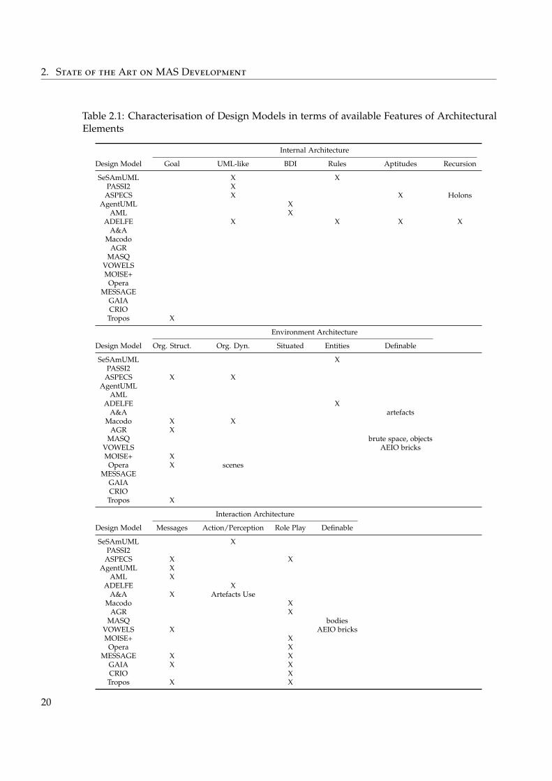
2. State of the Art on MAS Development
Table 2.1: Characterisation of Design Models in terms of available Features of ArchitecturalElements
Internal Architecture
Design Model Goal UML-like BDI Rules Aptitudes Recursion
SeSAmUML X XPASSI2 X
ASPECS X X HolonsAgentUML X
AML XADELFE X X X X
A&AMacodo
AGRMASQ
VOWELSMOISE+
OperaMESSAGE
GAIACRIO
Tropos X
Environment Architecture
Design Model Org. Struct. Org. Dyn. Situated Entities Definable
SeSAmUML XPASSI2
ASPECS X XAgentUML
AMLADELFE X
A&A artefactsMacodo X X
AGR XMASQ brute space, objects
VOWELS AEIO bricksMOISE+ X
Opera X scenesMESSAGE
GAIACRIO
Tropos X
Interaction Architecture
Design Model Messages Action/Perception Role Play Definable
SeSAmUML XPASSI2
ASPECS X XAgentUML X
AML XADELFE X
A&A X Artefacts UseMacodo X
AGR XMASQ bodies
VOWELS X AEIO bricksMOISE+ X
Opera XMESSAGE X X
GAIA X XCRIO X
Tropos X X
20
2.2. Walking Through the Different Aspects of MAS Development
– UML-like: the behaviour of the agents is described using an UML-like abstractionsuch as sequencing diagrams, state diagram, etc.
– BDI: the behaviour of the agents is described in terms of Beliefs-Desires-Intentions.
– Rules: the behaviour of the agents is described using rules.
– Aptitudes: aptitudes, skills and other kind of mechanisms that agents can refer toin their behaviour can be modelled.
– Recursion: agents can be recursively modelled as MASs.
– Environment Architecture: how the designer can model the environment of the agents.
– Organisation Structure: the structure of the agents organisation can be described,often in terms of roles and their relations.
– Organisation Dynamics: at the environment level, a dynamics for the organisationnot managed by the agents themselves can be described.
– Situated: consider agents are in a situated environment.
– Entities: entities in the environment with which the agents can interact can bedefined.
– Interaction Architecture: which interaction means the designer can use to model theinteractions between the agents.
– Messages: consider agents can communicate using message passing.
– Action/Perception: consider agents can perceive their environment and act on it.
– Role Play: consider agents play roles in an organisation.
The definable meta-feature has the following meaning: when no feature is available todirectly describe an element of the solution, MAS meta-models with a meta-feature providemeans to define abstractions adapted to describe the solution instead of using the (potentiallyinadequate) features of the meta-model. The boundary between a feature and a meta-featurecan be fuzzy, but as an example, message passing is typically not a mean to define newabstractions, while an abstraction usable to define new action and perception mechanisms is.
The important point to notice in this characterisation is that the features tackled by thesemeta-models are very different depending on the work. Some of them focus more on theinternals of the agents, while others tackle the environment itself. There are some worksabout the environment as an interaction medium, others try to define a way to describethe organisation the agents operate in. Moreover, in terms of architecture, be it internal orexternal, MAS meta-models have overlapping features or at different levels of abstraction.But at the same time, not two of them actually share the same set of features, except fora few exceptions. Thus they all cover different parts of what a MAS is, some of them arecomplementary, while others are exclusive.
A second point, which is not directly highlighted by the characterisation, is that thesemantics of the MAS meta-models are more or less precise. This is actually linked to thefact that they cover different parts of what a MAS is: a MAS meta-model focused on the
21
2. State of the Art on MAS Development
environment does obviously not say anything about the internal architecture of agents, butmaybe constrains the way agents can communicate. But moreover, even when a meta-modeldefines how a specific part of the architecture is structured, it can omit details of the semanticsof it. A good example is about all the MAS meta-models defining that an agent has aperceive-decide-act cycle: does it mean the agent is reactive and reacts to every percept thatoccurs following this cycle, or does it means that there is a general loop where in the perceivestep, the agent checks its percepts? This has to be defined at one point or another, but someMAS meta-models don’t provide any information on that. We come back on the implicationof that matter later.
The third and last point on these works is about the architecture style that MAS meta-models follow. Indeed, MASs are made of agents and their environment, which are inter-acting together in a dynamic and peer-to-peer way. From a software architecture point ofview, this is seen as a family of architectural styles — as highlighted Chapter 1 — respected byalmost all the MAS meta-models, even though they all focus on different parts of it. Elementsof the system are the agents, they have autonomy, but more importantly, they are not directlyconnected to other particular agents: they only have access to interaction means that give themthe possibility to communicate with whoever they know. That last point contrasts particularlywith common means of interaction between software elements in other existing approachesfor software decomposition. For example, in component-based programming, elements areconnected explicitly with connectors, and in object-oriented programming, elements directlyknow each other and interact only by synchronous calls. This is of importance because thisfact has an impact on the implementation as we are going to see.
To conclude, there is a lot of diverse meta-models that are used to design MASs. They areusable to describe the system in diverse ways at different levels, but all with the same kindof architectural style. They do so in a more or less precise way giving some latitude to thedesigner and developers for choosing a specific semantics for it.
In terms of our objectives of easing the development, something else is of importance:these MAS meta-models are the support of numerous works and MAS approaches, and thustheir use cannot simply be avoided. They are tools that researchers and engineers want andshould use to build applications based on MASs. This is of first importance since it constrainsthe solutions that can be proposed to ease the development of MASs.
2.2.2 Diversity of Requirements
The previous section presented MAS meta-models where all of them act as a mean tocapture a way to realise a system for a specific problem. At the start of every development,what these systems should do is expressed using requirements. This is the subject of thisFor a defi-
nition of Re-quirements,see p. 7
For a defi-nition of Re-quirements,see p. 7
section.The first thing to say about these requirements is that depending on the MAS meta-model
used, different kinds of requirements are answered. Some works see MAS approaches asa mean to provide some quality attributes for the system to be built and analyse them inorder to help choosing a development method. For example, Silva et al. (2004) proposes
22
2.2. Walking Through the Different Aspects of MAS Development
categories of non-functional qualities that a MAS can have and classifies some developmentmethods in these categories. The preface of the Multiagent Systems and Software Architecture(MASSA) workshop (Weyns and Holvoet 2006) also states that MAS are meant to answerquality attributes such as adaptivity, robustness or scalability. This idea is also defendedby Weyns (2010). On top of these, which are mostly non-functional requirements, the MASmeta-models are obviously able to describe solutions answering the functional requirementsof the application. A work that is well known for emphasising the importance and diversityof requirements is the Tropos method (Giorgini et al. 2005).
Actually, MAS meta-models only answer a subset of them: for example the use cases(which are expressions of functional requirements) involving the user of the application areoften not fully answered by the MAS methods and their meta-models themselves. Parts ofthem are left at the discretion of the developer. Indeed, in MASs, there are requirements thatare answered by the MAS itself, such as the main functionality of the application, or the qualityattributes previously referred to. But there are also more traditional functional requirementssuch as Graphical User Interface (GUI) for interacting with the system or the agents, or formonitoring them. There are also other non-functional requirements more concerned withorganisation of the development such as modularity, reusability, cost management, etc. Thus,every MAS meta-model in the literature tackles requirements, but none of them ever answersall the requirements of one application at once: this means there is always requirementsthat must still be answered after an approach and its MAS meta-model has been applied.
Moreover, a point often forgotten about requirements in MASs is that the choice of aMAS meta-model and the resulting design both introduce new requirements that haveto be tackled during implementation. Indeed, as we said earlier, all MAS meta-modelsmake hypothesis on the way agents are internally organised, or on the kind of interactionmeans they can use, or the interaction language they exploit. When the design is done andimplementation has to start, new requirements and constraints have appeared and mustbe taken into account. Be it using an existing development platform, as we see after, or bybuilding everything by hand, this has to be done. For example, a MAS meta-model canassume that agents are all synchronised in their execution, as it is always done in simulation,for the result of the design to be valid. In a way, these introduced requirements are theexpression of the semantics of the MAS meta-model.
To conclude, the MAS meta-models help to tackle diverse requirements and also introduceother new requirements that constrain the implementation. When developing a MAS, adesign approach, and thus a MAS meta-model, is chosen and this has an impact on what canbe answered, and how it will be answered. Of course, this question of requirements is verycommon in the software architecture field as being the main reason why an architecture isdefined.
What is important to notice from this section is that all of these requirements have to betaken into account, as early as possible, and as easily as possible. This must be rememberedto be able to propose an adequate solution for easing the development of MASs.
23
2. State of the Art on MAS Development
2.2.3 Commonality of Requirements and Elements of Solution
As we saw, all the requirements that we talked about must be taken into account. Whatcan now be said is that some requirements are mostly common to MASs while other are veryspecific to some applications. Also, some are very common to software in general, while otherare only found in specific sub-domain of the MAS field. For example, adaptivity is often aknown requirement answered by MASs, while execution fairness or monitoring of the agentexecution is mostly a problem in the simulation domain. Security finds itself more in the weband internet applications, performance in the optimisation domain. Then, as we said earlier,different approaches and MAS meta-models are also introducing new requirements, whichare thus specific to them.
In practice, these requirements are answered by some elements of the built solution. Theseelements can manifest themselves as bit of code such as mechanisms, datatypes but alsohigh-level designs. When one wants to reuse in order to not reinvent the wheel every time anapplication is developed, one can use code, patterns or other means of reusing knowledge asit was presented Chapter 1. On the other hand, some elements have to be implemented onpurpose for the application.
To get a clear vision of the specificity or generality of requirements and elements ofsolution, we propose a simple classification as following, going from the problem to softwaredevelopment in general:
– Problem/Application/Project: they are specific to the problem at hand, they often con-cern functionality, but also requirements for the development itself such as modularityand organisational constraints. They are about GUIs, behaviours of the agents, etc.
– Domain: they are concerned by a set of problems or application, examples of do-mains are optimisation or simulation. They are about monitoring GUIs, schedulingmechanisms, environment management.
– Approach: they are concerned with specific approaches and MAS meta-models, theyconstraint the implementation for example for the lifecycle of the agents or the way theycan interact. An example is rule engines for executing behaviours described using aspecific method.
– MAS: they are about MAS in general, for example the adaptivity requirements or thefact that the system is architectured as agents and environment.
– Others: they are anything that is not concerned with the previous ones.
Some works focused on applying the SPL approach to tackle this commonality: mainFor a defini-tion of Soft-ware ProductLine, see p. 8
For a defini-tion of Soft-ware ProductLine, see p. 8
works on the matter of MAS Product Line (MAS-PL) are DDEMAS (Girardi and Lindoso2006), MaCMAS (Peña et al. 2007), Nunes et al. (2011) (based on PASSI) and GAIA-PL(Dehlinger and Lutz 2011). The differences between them are on the phase of design, thetypes of variability points identified and the methods and techniques they were inspired by.
A second set of works are about design or architectural patterns. Some of them focus onFor a defini-tion of Archi-tectural Pat-tern, see p. 8
For a defini-tion of Archi-tectural Pat-tern, see p. 8
organisation of agents for specific objectives, while others are about coordination mechanisms,mainly environment-mediated, to tackle some common problems. Huge surveys of existing
24
2.2. Walking Through the Different Aspects of MAS Development
patterns in MAS were produced (Oluyomi 2006; Oluyomi, Karunasekera, and Sterling 2007).These works classify them depending on the phases of development they are useful for andthe tasks that are tackled in these phases. Some works regrouped sets of patterns in referencearchitectures or in pattern languages. Most of these works focused on the environment-mediated types of MASs (Weyns, Omicini, and Odell 2006; Viroli et al. 2007). This can beexplained by the diversity of interaction means and the few development supports availablefor implementing this kind of MASs.
As a conclusion, there is a lot of diverse requirements, but a lot of them can be recurringin different applications. The answer to these requirements can be found as reusable mecha-nisms, patterns or any other way to capture experience. This at the design level, but also atthe implementation level.
Thus, this is an important point to take into account to ease the development: if possible,development by and for reuse must be possible.
2.2.4 The Implementation Point of View
A common mean of reuse existing known way to implement MAS — and thus by theway to answer some recurring requirements — is to use development supports. The MASscommunity proposed several platforms, frameworks and programming languages adapted toMAS development.
In a rough way, the link between these three means of implementation is as follow.Programming languages and frameworks are means to declaratively or imperatively describeelements of a MAS. The difference is that languages have programming primitives dedicatedto their domain while frameworks provide their programming abstractions to their hotspotsin a more general programming language such as an object-oriented one. In order to executethese descriptions, there exist execution platforms for them. In the case of frameworks,it is comprised in their frozenspots. For the languages, it is more like abstract machinesthat can execute the language or compiler that can transform the language into executablecode. Moreover, platforms provide the infrastructure needed for the agents to work, such ascommunication or spatial interactions for example.
Available agent programming languages are usable to specify agent behaviours withadapted programming primitives. The main origin of programming languages in the MASfield comes from the Agent-Oriented Programming paradigm (Shoham 1993) that proposesto describe agents in terms of their states and mind. The most famous known applications ofthis approach are the Belief-Desire-Intention (BDI) languages (Bratman 1999).
Table 2.2 shows development supports meta-models categorised as presented previously.Only those with an existing and available implementation are present. Moreover, in the caseof development supports relying on others, the name of the development support relied on iswritten in italics in features it provides.
We now detail the different features existing for each of the types of architecture elements:
– Agents Internal Architecture: how the programmer can implement the behaviour of theagents or elements of its internal architecture.
25
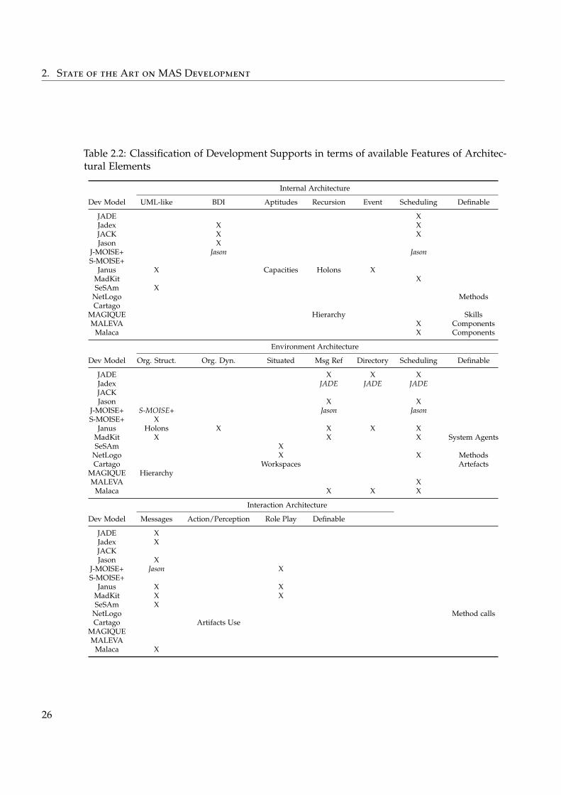
2. State of the Art on MAS Development
Table 2.2: Classification of Development Supports in terms of available Features of Architec-tural Elements
Internal Architecture
Dev Model UML-like BDI Aptitudes Recursion Event Scheduling Definable
JADE XJadex X XJACK X XJason X
J-MOISE+ Jason JasonS-MOISE+
Janus X Capacities Holons XMadKit XSeSAm X
NetLogo MethodsCartago
MAGIQUE Hierarchy SkillsMALEVA X Components
Malaca X Components
Environment Architecture
Dev Model Org. Struct. Org. Dyn. Situated Msg Ref Directory Scheduling Definable
JADE X X XJadex JADE JADE JADEJACKJason X X
J-MOISE+ S-MOISE+ Jason JasonS-MOISE+ X
Janus Holons X X X XMadKit X X X System AgentsSeSAm X
NetLogo X X MethodsCartago Workspaces Artefacts
MAGIQUE HierarchyMALEVA X
Malaca X X X
Interaction Architecture
Dev Model Messages Action/Perception Role Play Definable
JADE XJadex XJACKJason X
J-MOISE+ Jason XS-MOISE+
Janus X XMadKit X XSeSAm X
NetLogo Method callsCartago Artifacts Use
MAGIQUEMALEVA
Malaca X
26
2.2. Walking Through the Different Aspects of MAS Development
– UML-like: can execute behaviours described using an UML-like abstraction.
– BDI: can execute behaviours described in terms of Beliefs-Desires-Intentions.
– Aptitudes: abstractions to implement unit of aptitude, skill or other mechanisms.
– Recursion: usable to define agents as MASs.
– Event: provide abstractions to implement and execute behaviours triggered byevents.
– Scheduling: provide specific scheduling means for executing behaviours, oftenadapted to the other means of internal architecture implementation.
– Environment Architecture: how the programmer can implement elements of the envi-ronment.
– Organisation Structure: abstractions to describe the organisation structure and takecare of its management.
– Organisation Dynamics: abstractions to describe and execute the organisationdynamics.
– Situated: to execute and manage situated agents and visualise them.
– Directory: provide a directory to register and find agents.
– Scheduling: implement scheduling mechanisms for executing the system in acoherent (not necessarily synchronised) way.
– Interaction Architecture: which interaction means the programmer can use to implementthe agents.
– Messages: provide means for agents to exchange messages.
– Action/Perception: provide abstractions to describe way of interacting with theenvironment.
– Role Play: provide abstractions to take part in an explicit organisation.
The definable meta-feature has the following meaning: they are abstractions provided bythe development support meta-model to define features instead of defining elements of thesolution directly using a given feature. We can clearly see the difference between these twoways through their use when no feature is adapted to the elements to be implemented: ameta-feature can be used to produce their implementation in a direct way, possibly throughthe definition of a new feature, while without a meta-feature, an existing feature have to beadapted or extended to implement the element.
These meta-models provide abstractions to program a MAS design. They range fromvery specific such as adapted to a MAS meta-model, to very general such as a generalprogramming language. Others take an orthogonal stance and provide their own meta-modelthat can be used with a subset of all the available MAS meta-model.
In any way, this classification shows the same kind of conclusion than with the MASmeta-models. They also have overlapping features at different levels of abstraction, and at thesame time not two of them actually share the same set of features, except for a few exceptions.
27
2. State of the Art on MAS Development
But differently than with the MAS meta-models, the architectural styles followed by theimplementation meta-models are much more diverse. For example, in simulation platforms,agents are just behaviours that are executed in a sequential and synchronised way withoutany independence from each other or the environment in terms of software elements. Otherdevelopment supports enforce the separation and have a clear distinction between the agentsas software entities and the platform as the environment infrastructure as called by Weynsand Holvoet (2006).
What is important here is that when choosing a specific development support meta-model (if one wants to implement its design) the developer have to rely on its semanticsfor implementing his application. This means that there is an effort to make the conceptsmanipulated at design and at implementation coincide.
A second interesting point about development supports is that they have an other objectivethan just reusing implementation and design. They also are a mean to ease the developmentby providing adequate abstractions to the MAS developer. The MAS developer does want tofocus on his design, on his problem, or, should we say, on his business concerns. In the worldof MAS design, the user of the MAS meta-models and approaches are not always expertprogrammers on the subject of concurrency or distribution. He does not want to bother withtechnical problems — such as synchronisation between agents, spatial movement management,etc — but to work using high-level abstractions. They can be sociologists studying socialbehaviours, people interested in constraint optimisation, etc. That’s why existing developmentsupport are used extensively to abstract over the details of the implementation in order tofocus on what is their business. They of course are usable to implement the MAS design, butalso other things that are linked to any of the requirements they can have. Example of thisare the need for having control on how data is shown in simulation.
2.2.5 From Design to Implementation
The previous sections highlight the gap between the concepts manipulated at design andthose manipulated at implementation that was implicitly present since the beginning of thiswalk-through. The gap is well presented by Molesini, Denti, and Omicini (2007): they explainthat while the MAS meta-models are interested in agent-oriented solutions, the developmentsupport meta-models are more inspired by object-oriented languages and practical concerns.A huge quantity of works try to solve this problem.
Some of them are dedicated to specific MAS and development support meta-models(Amor, Fuentes, and Vallecillo 2005; Sudeikat et al. 2005; Molesini, Denti, and Omicini 2007;Pavón, Gómez-Sanz, and Fuentes 2006; Rougemaille et al. 2009). Others try to compose existingMAS meta-models in order to adapt the process to the development support (Mariachiaraet al. 2010). Others provide kind of IDEs to support the implementation of specific MASmeta-models such as INGENIAS Development Kit (IDK) (Pavón, Gómez-Sanz, and Fuentes2005), which supports INGENIAS, or Shell for Simulated Agent Systems (SeSAm) (Klügl,Herrler, and Oechslein 2003), which supports SeSAmUML.
28
2.2. Walking Through the Different Aspects of MAS Development
Finally other works focus on unifying, generalising or composing existing MAS meta-models. Works (Beydoun et al. 2005; Bernon, Cossentino, Gleizes, et al. 2005; Dalpiazet al. 2008) propose to unify a set of MAS meta-models by finding common concepts inthem. By doing so, only one development support adapted to this meta-model can beproposed. Another (García-Magariño 2009) proposes to easily transform between existingMAS meta-models by defining instantiation of meta-concept using powertype modelling.Hahn, Madrigal-Mora, and Fischer (2009), on the other hand, propose a general developmentsupport meta-model to which should be provided instantiations depending on the used MASmeta-model. From this general meta-model it is possible to generate an implementation.
To conclude, these works try to answer this matter either by proposing unifying MASor development support meta-models that can either be used with a generic developmentsupport or at least that can be used to generate what is not generic. But as we highlightedearlier, even though these are meant to be generic, MASs meta-models are so diverse thatgeneric solutions to the matter are actually specific in the sense that they only focus on oneMAS meta-model. And as we said, each MAS meta-model can not completely answer therequirements of one particular problem to be solved. While this bridges the gap betweendesign and implementation, it only does so in an ad-hoc (although adapted to a MASmeta-model) way.
2.2.6 Practical Observations
All of this has practical implications of the development when combined with our ownobservations and assumptions on how development is done.
First, as we observed, assumed from existing works in the literature or personally experi-enced, it seems that the actual practice in MAS development is to use one of the followingsequence of tasks:
– Choose a development support before the design, choose a MAS meta-model that fitsto it, do the design constrained by these and finally implement the system.
– Choose a MAS meta-model, do the design, choose a development support that fits to it,and finally implement the system.
– Choose a MAS meta-model, do the design and directly and completely implement thesystem by hand.
In all the cases, the meta-model chosen can be one of those presented previously and the wayused to implement the system can be using one of the tools or transformation presented here,or by hand.
What is interesting with that is that in the first two cases this means that it is needed toeither adapt the design to the development support, or to either adapt the developmentsupport to the design. This has several impacts, of course as we just saw for actually bridgingthe gap, but also on the ease of development itself. There is people that use the existingdevelopment support as a mean to have high-level abstraction adequate to their expertise.Inversely, the people that implemented these supports are expert on implementing such
29
2. State of the Art on MAS Development
abstractions. They know what are the best way of tackling some of the requirements that areanswered by the development support.
These two different sets of developers depend on each other: the users of the develop-ment support highly depend on their creators to have something adapted to their design.This is particularly important in MAS because of the diversity of available meta-models fordesigning as well as implementing. Furthermore, all of this is exaggerated by the fact that theconcepts at design are not always semantically very precise as it was said earlier.
Also, another fact that makes the previous even more problematic is that methods andapproaches try to make the design more and more refined during the development and notonly as a first step of it. Indeed, when developing MAS, it has been observed that the processof implementing and design is a very iterative, agile process. This is visible in methodswhere a quantity of iterative phases exists. In the specific case of MAS, the need for such aniterative approach to design has been highlighted by Georgé et al. (2003). In this work, theauthors go further than just design and implementation, and talk about living design: theidea of running the system and modifying it until it realises the wanted functionality.
In practice, when participating in developments and interacting with people developingMASs, observations, experiences and feedbacks are that people are constantly revising theirdesign during the implementation of their system.
Something else we noticed is the fact that some requirements are taken into accounttoo late in the development process. A very common example of such requirements is thescheduling of the system, the way agents are synchronised, and their execution is ordered.Even though this has an important impact on the behaviour of the system as a whole, this isoften kept implicit during MAS design and taken care of at implementation time when it istoo late to handle the impacts on the MAS design of a choice of scheduling strategy. Such badpractices are mostly caused by the fact that existing methods does not take such requirementsin account as it was highlighted for example by Weyns et al. (2004).
2.3 Analysis: Should We Tweak or Build?!
In this section, we propose an analysis of the previously presented state of the art of MASdevelopment. We give our opinion and criticise the way things are currently done in order tomotivate the contribution of this thesis.
From the matter of requirements, which are the input of the development, and mov-ing towards the problem of the gap between design and implementation, we look at thearchitectural implications of these aspects of MAS development.
With a general point of view, when building a MAS we can differentiate several phases.The development starts from the requirements and specifications that describe what the
system as a whole must do. Based on these requirements, an analysis followed by a designphase are done in order to define a MAS architecture made of agents and their environment.This is where the existing MAS method and their meta-models are used and the result of it isa system described in terms of the agents, their environment and their interactions. It defines
30
2.3. Analysis: Should We Tweak or Build?!
what are the agent behaviours, which interaction means they use, what is the dynamics ofthe environment and the potential entities existing in it.
At this point of the design, the work of the MAS designer is finished and the MASarchitecture has to be implemented:
– Sometimes the concepts used at the level of the MAS architecture can be used directlyto program the final application: these programming abstractions, adapted to thoseneeded by the MAS architecture, are provided by a development support. For example,a design expressed in terms of rules “perception implies action” is implementable usinga development support where one can express only the rules and not how they areprocessed.
– Sometimes some adjustments have to be made, either to extend existing developmentsupports (adding or modifying the abstractions) or to connect them to existing softwaresystems. For example, a design can rely on a communication protocol that must beimplemented on top of the messages passing abstraction available in the developmentsupport.
– Some other times the final application is totally implemented, including what wouldhave been provided by a development support.
The first case does unfortunately never happen, except maybe when building a firstprototype, as we did show that every application has its particular requirements. The secondcase, which we call “tweaking”, is maybe the most widespread, the idea being to reuse asmuch code as possible. The third case, which we call “building”, does actually also oftenhappen, in particular in the ABM field where the design is strongly linked to the domain ofthe problem and the abstractions needed are thus very specific to it.
2.3.1 The Gap, Again
The explanation for the existence of these two approaches to implementation is that, as wehighlighted, not every type of requirement is tackled by every MAS meta-model and someof them are even introduced by MAS meta-models themselves. This is again the questionof bridging the gap: how to take all of these requirements into account? We start from thisquestion to detail the two approaches.
“Tweaking”. The most widespread solution taken by current practices is to use a MASmeta-model, answering a subset of these requirements, and choose a development supportand its meta-model (compatible with the MAS meta-model) that answers another subsetof them. Then, the design is done according to the constraints given by the two chosenmeta-models and finally the implementation is adapted by hand to answer the remainingrequirements.
Such practices often destroy the original intent of the MAS designer by constraining theway his system is designed with the development support. They don’t promote adequateabstractions at the level of the expertise of the MAS developer. In a much broader way, every
31
2. State of the Art on MAS Development
time any development support is used, either one has to adapt the design to the developmentsupport meta-model, or the development support meta-model has to be modified for thespecific design. When directly using the development support abstractions in the MAS design,the latter is polluted with unwanted concepts that do not fit the design. When modifyingabstractions provided by the development support, there are two possibilities. Either it meansgoing into the inside of the development support, which is not meant to be modified by anyMAS developer but mainly by the software authors. Or it means building new abstractionsusing existing ones, which is not always adapted and introduces complexity in the softwareproduced.
And even if the development support perfectly fits the MAS meta-model, which is the caseonly when using a development support made for a MAS meta-model and an applicationdomain, as we highlighted before there is much more requirements that can have an impact onthe implementation and that need again adaptation of the development support meta-modelfor the specific problem that is solved. A simple example of that is the integration of the MASwith other systems: that cannot possibly be already present in the development support.
“Building”. The other solution available is to build by hand the development support.Obviously, this is a time consuming and inefficient activity. As we highlighted, there is a lotof things that are generic with respect to some aspects of the system to build, and thus with“building” reuse is not easily done.
In a less extreme way, “building” is currently often done when using a developmentsupport that covers just a part of the architecture of the system. For example when using adevelopment support focused on the internal architecture of the agents and the MAS designrelies on environment-mediated interactions. This part of the implementation is often doneusing a general programming language, which means that it involves a lot of low-level andcomplex expertise that every MAS developer does not have. For the sake of completeness,choosing a development support that introduces environment-mediated abstractions stillmeans there can be other things to “build” or “tweak”. For example scheduling of the systemis often imposed by the chosen development support, and thus is not always adapted. And ifit is not imposed, it thus have to be implemented.
So What? The point here is not to say that all the development supports should be thrownaway, but that in a general vision of MAS development, existing development supports aretoo constraining to cover all the possibilities and that there always exists a class of applicationsthat does not fit the meta-models provided by existing development supports.
What we argue here is that meta-models of development supports should not be con-sidered in the same way than meta-models for MAS design. While the latter are somethingthat developers want to use, because they answer some of their requirements, the former aresomething they spend a lot of time to adapt, tweak, modify, extend to fit the rest of theirrequirements as well as the MAS design. Since it is not possible to have a “one-size-fits-all”development support, it means that it is necessary to ease the building or tweaking of
32
2.3. Analysis: Should We Tweak or Build?!
the adapted development support. There is thus a need for defining and implementingsuch development support in an easy, composable and flexible way, and with reuse. Notsurprisingly, that’s the admitted goal of software architectures engineering and that’s whatwe are going to do.
Before entering into the details of that point, we briefly come back to our analysis.
2.3.2 Types of Agents and Adequate Abstractions
What we noticed, when doing this state of the art is that if we accept that MAS has tobe done using existing MAS meta-models and methods for its design, then something musthelp to bridge the gap between design and implementation. Moreover this something mustdo it in a way that it is adapted to all the requirements of the problem, as well as thoseintroduced by the design itself. This something is what we call a type of agent. Everyapplication has its own type of agents, with its own specificities but also commonalities withother types of agents. A type of agent is a precise semantics given to the abstractions usedto implement the design, inferred from the latter, from all the requirements of the problemto solve, from the expertise of the developer, etc. For example, defining one type of agentis to say that the agents of one application are interacting by exchanging messages, movingbetween distributed computers where artefacts (as in Agents and Artifacts) are usable withspecific interfaces, executed concurrently in a reactive manner to a set of events such asmessages received and timers. Of course, nothing prevents a given application to have severaldifferent types of agents using overlapping interaction means.
While MAS design is about building an architecture made of agents and their environment,now the question is about building the architecture that supports the abstractions used bythis design. It means building the types of agents and the platform that makes them live.Actually, every development support studied here is an instance of such an approach, but weargue there is a need to do that more easily, faster, better and with more reuse in order toapply it to every MAS development. As we saw, these development supports are based onone meta-model, or, as we can now say, one type of agents. To do so, these supports have theirown architecture, made of software entities that are dynamically created, interacting usingdiverse interaction means, and made of a platform through which this interaction takes placeand that contains the environment and all the other tools such as GUIs, monitoring tools,etc. Thus, we need to be able to build a kind of application-specific development supportadapted to the types of agents of the application to build.
The second point that this application-specific development support must answer, isrelated to the different expertises of the MAS developers. Indeed, we saw that dependingon the field or the problem, the developers do not have the same expertise, and we actuallynoticed that there is two main kinds of developers in the MAS world: those that are concernedwith the business aspects of the problem they are tackling, and those that are concernedwith the operative aspects of the solution to build. There is thus a need for having adequateabstractions for the first set of developers. Moreover, this question coupled to the moremethodological one of the iterative development bring us another need. This kind of agile
33
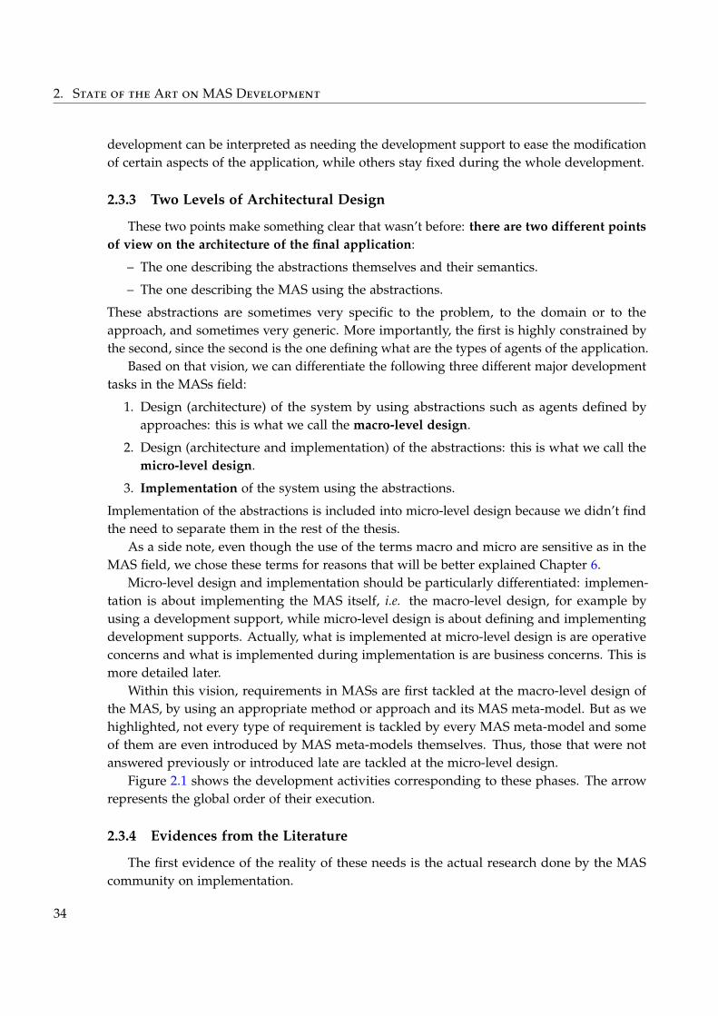
2. State of the Art on MAS Development
development can be interpreted as needing the development support to ease the modificationof certain aspects of the application, while others stay fixed during the whole development.
2.3.3 Two Levels of Architectural Design
These two points make something clear that wasn’t before: there are two different pointsof view on the architecture of the final application:
– The one describing the abstractions themselves and their semantics.
– The one describing the MAS using the abstractions.
These abstractions are sometimes very specific to the problem, to the domain or to theapproach, and sometimes very generic. More importantly, the first is highly constrained bythe second, since the second is the one defining what are the types of agents of the application.
Based on that vision, we can differentiate the following three different major developmenttasks in the MASs field:
1. Design (architecture) of the system by using abstractions such as agents defined byapproaches: this is what we call the macro-level design.
2. Design (architecture and implementation) of the abstractions: this is what we call themicro-level design.
3. Implementation of the system using the abstractions.
Implementation of the abstractions is included into micro-level design because we didn’t findthe need to separate them in the rest of the thesis.
As a side note, even though the use of the terms macro and micro are sensitive as in theMAS field, we chose these terms for reasons that will be better explained Chapter 6.
Micro-level design and implementation should be particularly differentiated: implemen-tation is about implementing the MAS itself, i.e. the macro-level design, for example byusing a development support, while micro-level design is about defining and implementingdevelopment supports. Actually, what is implemented at micro-level design is are operativeconcerns and what is implemented during implementation is are business concerns. This ismore detailed later.
Within this vision, requirements in MASs are first tackled at the macro-level design ofthe MAS, by using an appropriate method or approach and its MAS meta-model. But as wehighlighted, not every type of requirement is tackled by every MAS meta-model and someof them are even introduced by MAS meta-models themselves. Thus, those that were notanswered previously or introduced late are tackled at the micro-level design.
Figure 2.1 shows the development activities corresponding to these phases. The arrowrepresents the global order of their execution.
2.3.4 Evidences from the Literature
The first evidence of the reality of these needs is the actual research done by the MAScommunity on implementation.
34
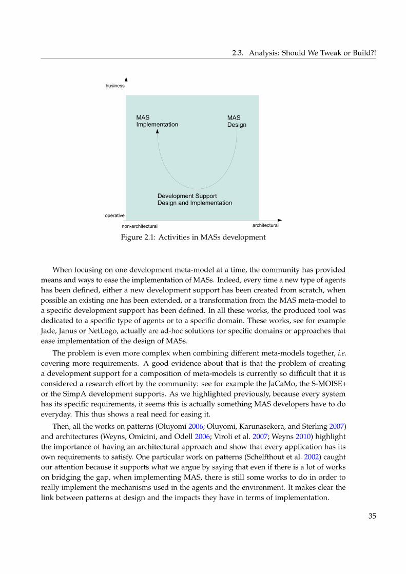
2.3. Analysis: Should We Tweak or Build?!
MASImplementation
Development SupportDesign and Implementation
MASDesign
non-architectural architectural
business
operative
Figure 2.1: Activities in MASs development
When focusing on one development meta-model at a time, the community has providedmeans and ways to ease the implementation of MASs. Indeed, every time a new type of agentshas been defined, either a new development support has been created from scratch, whenpossible an existing one has been extended, or a transformation from the MAS meta-model toa specific development support has been defined. In all these works, the produced tool wasdedicated to a specific type of agents or to a specific domain. These works, see for exampleJade, Janus or NetLogo, actually are ad-hoc solutions for specific domains or approaches thatease implementation of the design of MASs.
The problem is even more complex when combining different meta-models together, i.e.covering more requirements. A good evidence about that is that the problem of creatinga development support for a composition of meta-models is currently so difficult that it isconsidered a research effort by the community: see for example the JaCaMo, the S-MOISE+or the SimpA development supports. As we highlighted previously, because every systemhas its specific requirements, it seems this is actually something MAS developers have to doeveryday. This thus shows a real need for easing it.
Then, all the works on patterns (Oluyomi 2006; Oluyomi, Karunasekera, and Sterling 2007)and architectures (Weyns, Omicini, and Odell 2006; Viroli et al. 2007; Weyns 2010) highlightthe importance of having an architectural approach and show that every application has itsown requirements to satisfy. One particular work on patterns (Schelfthout et al. 2002) caughtour attention because it supports what we argue by saying that even if there is a lot of workson bridging the gap, when implementing MAS, there is still some works to do in order toreally implement the mechanisms used in the agents and the environment. It makes clear thelink between patterns at design and the impacts they have in terms of implementation.
35
2. State of the Art on MAS Development
Finally, Weyns et al. (2004) show that existing methods for MASs do suffer from twoproblems: lake of coverage of the complete architecture of the MAS by the proposed MASmeta-models and abstractions that are inadequate for the level of abstraction needed bynon-architectural design. While the conclusions and criticisms are aimed at the methodsand the way they tackle software development, this work shows well that there is a needfor more ways of going farther in architectural design than what is currently proposed byexisting methods and their MAS meta-models. It also confirms the idea that the architecturaldesign of a MAS should take into account the whole system and its requirements, and thusexisting development supports are not enough by themselves. Moreover, it supports the ideathat some requirements are not taken into account soon enough as we highlighted in ourobservations Section 2.2.6.
2.3.5 Existing Answers
To support principles of software architectures — better software quality, maintainabilityand reuse —, which we argue as being necessary to build a development support, few workstried to apply component-based or aspect-oriented approaches. The problem with these isthat they only focus on specific type of agents and mainly on the behavioural part of them.The most famous examples of these are Generic Agent Model (GAM) (Brazier, Jonker, andTreur 1999), MALEVA (Briot, Meurisse, and Peschanski 2007), Magique (Routier, Mathieu,and Secq 2001) and Malaca (Amor and Fuentes 2009).
Nevertheless, three other works caught our attention. They try to tackle directly the matterof the environment, but also shows some interesting points for easing the building of adapteddevelopment supports. They appear 2.2 as providing what we called the definable meta-feature.The first one is Volcano (Ricordel and Demazeau 2002), the second one is CArtAgO (Ricci,Viroli, and Omicini 2007) and the last one is Agent-Environment Interface (AEI) (Behrenset al. 2011).
Volcano is particularly interesting because it makes explicit the need for building a specificarchitecture supporting the system. Actually, it covers part of our objectives, as the authorshighlight, by enabling to build dedicated types of agents for the application, at the agentbut also at the environment level. The main problem with this work is actually that noimplementation is available and that it seems to be discontinued. Except from the cited article,nothing has been found that clearly explains how things work in detail. It at least comfort usin the idea that it is the right way to go.
Then, CArtAgO, by proposing a general model of interaction of agents in any givenenvironment, coined some interesting abstractions to build, using what they call artefacts,elements of the system adapted to the modelled solution. But artefacts are entities that existas macro-level abstractions, they are not building blocks for defining new abstractions as it isdone with Volcano. Thus, although it is one of the closest solution to the questions we areasking, we are not convinced by it as a general approach to MAS micro-level design, mainlybecause it still constrains the model of MAS and agents that has to be followed, and becauseit does not take an architectural approach.
36
2.3. Analysis: Should We Tweak or Build?!
Finally, AEI proposes something different than the previous works because it does nottackle the building of the agents or the environment but just the interface between them. Itstill provides interesting insight on the problems that arises between the agents and theirenvironment, or should we say, as we are talking about actual implemented software, betweenthe agents and their runtime platform. In particular, we notice that the main problem whenconnecting several agents to one platform is the fact that the agents have to be kind of“referenced” by the platform in order for the signals coming from it to go to the right agent.
This is mostly that last point about the way things can be implemented to connect agentsto their runtime platform that motivates the need for a “good” definable meta-feature. Thisparticularity is also highlighted by the patterns proposed in (Schelfthout et al. 2002) or inworks about answering visualisation requirements in simulation (Louloudi and Klügl 2011).And of course, this is more generally visible in implementation of development supports orapplications.
2.3.6 Revisiting the Different Works
Before exploiting in the next section this analysis to extract challenges to answer forbridging the gap between design and implementation, we first propose a frame into whichthe state of the art as well as our contribution can now fit.
As we said, there are three different tasks during development: macro-level design, micro-level design and implementation. What interests us in these tasks are their products in termsof software artefacts in order to understand which research work is done for each of them.
We see two levels of understanding where research has been done for these tasks: base andmeta. The main idea behind these two levels is that some works try to solve some challenges— for example applying a MAS approach to a specific problem —, while other works tryto propose means to help solving such challenges in a more general way — for exampleproposing a development method dedicated to a class of problems —.
Table 2.3 shows how all the different works studied in this chapter fit in this classification.In this table, B1 stands for the base macro-level design, M2 for the meta micro-level design, etc.Every pair task/level contains a description of the kind of works that fit in it, then researchworks are categorised by their general subject of study. The category Jobs is about the kind ofjob researchers and engineers do without being subject to publication.
As a global introduction, this classification does not take into account works on method-ologies since it itself actually reflects a methodological vision of MAS development that is not For a def-
inition ofMethodology,see p. 4
For a def-inition ofMethodology,see p. 4
followed by existing works. We now look at each pair one by one to comment them.Base macro-level design (B1) is about producing specific MAS application to solve prob-
lems. It is empty, not because there is no work to put in it, but only because they are out ofscope of this thesis. Practical applications of MASs can be found in an extensive quantity ofconferences, workshops and journals on MASs.
Base micro-level design (B2) is about defining and implementing development supports.It is thus concerned with all the development supports and their meta-models presentedSection 2.2.4.
37
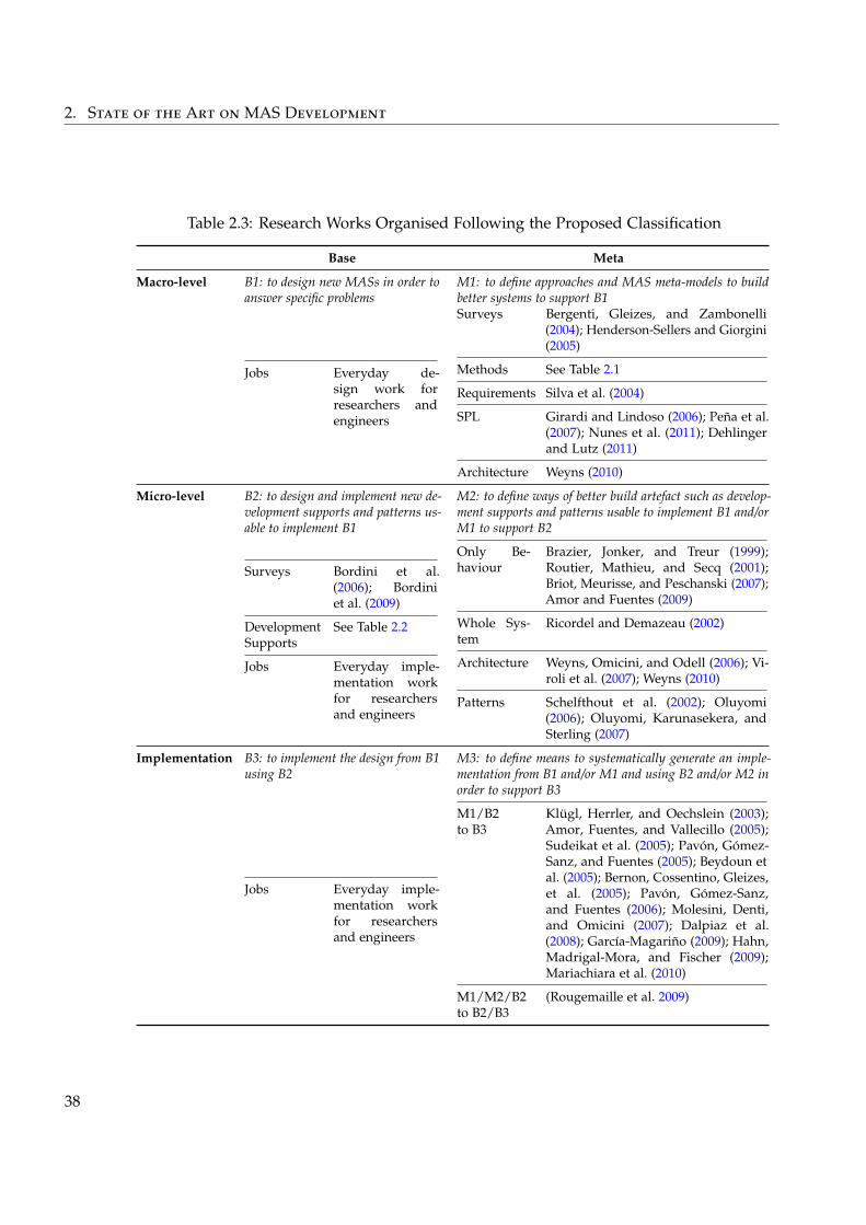
2. State of the Art on MAS Development
Table 2.3: Research Works Organised Following the Proposed Classification
Base Meta
Macro-level B1: to design new MASs in order toanswer specific problems
M1: to define approaches and MAS meta-models to buildbetter systems to support B1
Jobs Everyday de-sign work forresearchers andengineers
Surveys Bergenti, Gleizes, and Zambonelli(2004); Henderson-Sellers and Giorgini(2005)
Methods See Table 2.1
Requirements Silva et al. (2004)
SPL Girardi and Lindoso (2006); Peña et al.(2007); Nunes et al. (2011); Dehlingerand Lutz (2011)
Architecture Weyns (2010)
Micro-level B2: to design and implement new de-velopment supports and patterns us-able to implement B1
M2: to define ways of better build artefact such as develop-ment supports and patterns usable to implement B1 and/orM1 to support B2
Surveys Bordini et al.(2006); Bordiniet al. (2009)
DevelopmentSupports
See Table 2.2
Jobs Everyday imple-mentation workfor researchersand engineers
Only Be-haviour
Brazier, Jonker, and Treur (1999);Routier, Mathieu, and Secq (2001);Briot, Meurisse, and Peschanski (2007);Amor and Fuentes (2009)
Whole Sys-tem
Ricordel and Demazeau (2002)
Architecture Weyns, Omicini, and Odell (2006); Vi-roli et al. (2007); Weyns (2010)
Patterns Schelfthout et al. (2002); Oluyomi(2006); Oluyomi, Karunasekera, andSterling (2007)
Implementation B3: to implement the design from B1using B2
M3: to define means to systematically generate an imple-mentation from B1 and/or M1 and using B2 and/or M2 inorder to support B3
Jobs Everyday imple-mentation workfor researchersand engineers
M1/B2to B3
Klügl, Herrler, and Oechslein (2003);Amor, Fuentes, and Vallecillo (2005);Sudeikat et al. (2005); Pavón, Gómez-Sanz, and Fuentes (2005); Beydoun etal. (2005); Bernon, Cossentino, Gleizes,et al. (2005); Pavón, Gómez-Sanz,and Fuentes (2006); Molesini, Denti,and Omicini (2007); Dalpiaz et al.(2008); García-Magariño (2009); Hahn,Madrigal-Mora, and Fischer (2009);Mariachiara et al. (2010)
M1/M2/B2to B2/B3
(Rougemaille et al. 2009)
38
2.4. Challenges: Meta Micro-Level Design
Base implementation (B3) is about concrete implementation of such systems. It is alsoempty, but only because it concerns implementation of systems, which is not a subject ofpublication nowadays.
Meta macro-level design (M1) is about defining methods to support base macro-level design.Thus, it is concerned with all the methods, approaches and MAS meta-models presentedSection 2.2.1.
Let’s take a pause and first comment these. We can see that meta-models for MAS design(and accompanying methods) in M1 and for development supports in B2 are not consideredin the same way that it was in the beginning of this chapter. While the former is consideredmeta, the latter is considered base: this relates to our argument that it is possible to improve thebuilding of development support at an higher level than just proposing one-shot developmentsupports.
Meta micro-level design (M2) is about meta-models to support the building of basemicro-level design, i.e. development supports. It is thus concerned with all the meta-modelspresented Section 2.3.4 and Section 2.3.5. Not surprisingly, we can also find among them thedevelopment support meta-models with the definable meta-feature of Table 2.2. Works onpatterns provide ways to informally describe recurring solutions to recurring problems. Thoseon architecture focus more on how to do macro-level and micro-level design, without goingup to the implementation itself in a practical way. These lasts are still the most interesting onesthe design of MAS and bridging the gap towards implementation, which is not surprisingsince they follow a software architecture approach. Works in other fields than MASs exist andcan also fit in M2, but not without adaptations. This matter is actually presented extensivelyChapter 6 by relying on the contribution.
Meta implementation (M3) is about easing the implementation MASs and automatisingthe transition between different meta-models. It is separated in two categories depending onwhich kind of meta-models it bridges. The first one, M1/B2 to B3, is concerned with the workssurveyed Section 2.2.5. They go from a MAS meta-model to an existing development support(even if this one is a generic programming language). The second one, M1/M2/B2 to B2/B3,is concerned with works for a combination of a meta-model for design and a meta-modelfor defining adapted development supports. They automatise the production of micro-leveldesign but also implementation of the macro-level design, possibly by reusing previouslyrealised piece of micro-level design. The only work present in M3 is based on a prototypeversion of the contribution of this thesis. It does not actually completely answer the problembut is a first step in this direction.
2.4 Challenges: Meta Micro-Level Design
From the survey of this classification, we argue that the problem to the gap from design toimplementation can only be tackled by providing complete models for meta micro-leveldesign in order to later automatise the production of software by proposing works for metaimplementation.
39
2. State of the Art on MAS Development
The contribution of this thesis mainly tackles such meta micro-level design by helping tobuild application-specific development support. Actually, what is presented in this thesis fitsin several places of the classification. This will be developed Chapter 5, but in few words, thecontribution consists of a general methodology of MAS development that covers the wholemeta axis, a model and a method that fit into meta micro-level design, and all the softwareartefact that can be produced using this model, in particular a library of reusable artefacts, fitinto base micro-level design as well as base implementation.
In order to be able to provide ways to build application-specific development support, aset of challenges have to be answered.
First, because of the way MASs, as a macro-level design, is architectured, there is a specificbut broadly defined architectural style that has to be followed: agents as software entitiesare interacting together using interaction means provided by their runtime platform, whichalso has the role of executing them. Moreover, they are not only connected to their platformfor business interaction means: there is also operative connection between agents and theirplatform. For example when a GUI shows information from all the agents of a system, orwhen the agents are all synchronously executed by the a global scheduler as in simulationapplications. This is the way things are done in existing development platform, even if thereis variations about it depending on the requirements they cover.
To simplify the discourse when talking about these two usages of the abstraction, wename them interconnection mechanisms.
By looking at existing answers to the problem — analysed in the previous section —, afterstudying existing development supports and building actual MASs from scratch, we haveidentified the following architectural and implementation challenges, tackled in this thesis:
– Define and implement interconnection mechanisms for connecting agents to the runtimeplatform and vice-versa.
– Define and implement types of agents with specific internal architecture and connectedto the runtime platform using the previously defined interconnection mechanisms.
– Provide dynamic creation of instance of these types of agents, as well as their dynamicconnection and initialisation.
– Make the reuse of such interconnection mechanisms and architectures easy.
In particular, with respect to the features presented Section 2.2.4, the main difficulty hereis to propose a “good” definable meta-feature for the interaction architecture. Indeed, it isnot about proposing a good abstraction for representing environment and interactions atthe macro-level design, but to be able to define new interconnection mechanisms and tocompose them in the architecture of the agent. This then supports the implementation ofthe macro-level design using reusable adapted abstractions. Some of these challenges areillustrated in the next chapter.
Then, more on the methodological side, in order to do this micro-level design andintegrate it in a more general vision of MAS development, we propose to answer the followingchallenges:
40
2.4. Challenges: Meta Micro-Level Design
– Propose a general vision of MAS development integrating macro-level and micro-leveldesign, and implementation with iterative and incremental development.
– Provide guidelines to identify the requirements that help the micro-level design.
– Provide guidelines to identify abstractions needed to build a dedicated developmentsupport for the MAS developer.
Of course, always with architectural concerns in mind, in order to increase the qual-ity of the produced software by applying software architecture practices and to make itsdevelopment realistic, these challenges have to be considered within the following constraints:
– Take all the requirements into account as early as possible in the development process.
– Improve software quality and in particular reuse, maintainability and evolution.
Recap of the Contributions⊕We highlights the particularity of MAS development characterised by the inadequatenessof using pre-built development supports.⊕We propose a classification of the research works in MAS development highlighting thecurrent lakes.⊕We extracts from the state of the art a set of architectural and implementation challengesfor building dedicated architectures usable in place of development supports.
41

CHAPTER 3Dedicated Micro-Level Software
Architectures for MAS Development
Now that ain’t workingThat’s the way you do it
Money for NothingDire Straits
This chapter presents a coherent set of answers to the different needs of MAS develop-ment by focusing on the specificities of MASs that were uncovered previously. It proposesarchitecture-centric methodological solutions to organise development and an approach basedon software components to support the design and the implementation of the system.
Our objective here is to ease the development of MASs, ease their maintenance andevolution, as well as increase reuse of produced artefacts. For that, we aim at building systemswith software quality in mind by applying well-known software architecture practices.
As the previous chapter concluded, in order to reach these objectives it is needed topropose means to ease what we called micro-level design. Micro-level design is aboutproducing an architecture usable as a development support on which the implementationof the MAS design — also called macro-level design — can rely. Indeed, when producinga MAS, the macro-level design is able to answer only a subset of all the requirements ofthe application, the rest has to be tackled after the design is done. Depending on the MASmeta-model and approach chosen, as well as the design choices made, the abstractions neededto implement the MAS design vary a lot. We named such abstractions types of agents: theyare the bridge between the macro-level design, that relies on them, and the micro-level designthat realises them.
This development phase is thus interested in producing such a micro-level design in orderto answer the remaining requirements as well as those introduced by the design itself. Thismicro-level design, once implemented, is then usable to implement the macro-level design.
43
3. Dedicated Micro-Level Software Architectures for MAS Development
This highlights the existence of two different roles in the development process, we characterisethem as interested in business and operative concerns.
We identified methodological and technical challenges that a solution to this problemmust answer:
– First, in order for this solution to be usable and integrable in a more general developmentprocess, it is necessary to clearly identify when it should be used with respect to existingMAS methods and MAS meta-models. It is also necessary to be able to identify therequirements that are tackled either by the macro-level design, those tackled by themicro-level design, those that pertain to the business concerns, those that pertain to theoperative concerns and how they all impact the architecture.
– Then, MASs are systems that conform to a family of architectural styles where agents— the components —, that can dynamically be created and destroyed, are interactingtogether and with their environment. For that they use interconnection mechanismsthrough a runtime platform without being directly connected to each other. Thisintroduces the question of how to define such interconnection mechanisms in order tobe able to instantiate agents and connect them to their platform, how to implementthem and how to make them reusable.
All of this should be answered in a way that the micro-level design results into an architectureusable as a development support adapted to the expertises of the MAS developers and theirbusiness concerns.
In the rest of this chapter, when using the terms agents and (runtime) platform we talkabout the runtime entities of the system. As we are going to see, what we propose here aremeans to describe and implement such entities.
The present chapter is thus organised as follow.
First, we introduce a general methodological vision of MAS development. We introduceterms and concepts that are meant to facilitate communication between stakeholders duringMAS development. This methodology gives a frame into which the rest of the contributionfits and identifies the different types of requirements that have to be tackled during MASdevelopment. It is illustrated by being instantiated with the ADELFE development method.The example developed in this illustration also serves as a mean to illustrate the architecturaland implementation challenges identified Chapter 2.
Second, we present a component model that supports the micro-level design and an-swers the identified technical challenges. Third, we propose a method that instantiate themethodology with this component model as a foundation. Then, in order to complete thesethree main contributions, we present how and what experience could be captured during theexploitation of the approach, and in particular how partially abstract architecture are realised.This manifests itself through reusable software artefacts and patterns.
Chapter 4 develops a complete application of the approach on a real world example, andChapter 5 discusses the contribution with respect to the objectives and challenges.
44
3.1. Characterizing MAS Development: Architecture-Centric Methodology
3.1 Characterizing MAS Development: Architecture-CentricMethodology
In this section, we propose our vision of the methodology of MAS development. Asexplained Chapter 1, by methodology we mean the set of principles that pertain to MAS For a def-
inition ofMethodology,see p. 4
For a def-inition ofMethodology,see p. 4
development in general and into which works on design and implementation methods fromthe field can fit it. Of course, the contribution that follows the presentation of these principlesalso fits in.
More precisely, in this chapter we present the following things that altogether constitutethis methodology:
– We clearly identify the different phases that can exist when designing and implementingMASs and how they relate to each other.
– We provide clear terms to talk about requirements, design and implementation artefacts.
– We identify the different types of requirements and how they relate to the differentartefacts produced in the development.
This methodology and the vocabulary that we present here are meant to facilitate com-munication among stakeholders in MAS development. It also serves as a basis to introduceSection 3.2 the SpeAD (Species-based Architectural Design) model and Section 3.4 SpEArAF(Species to Engineer Architectures for Agent Frameworks) method that together practicallyanswer the challenges collected previously.
We conclude this section by illustrating the methodology with the ADELFE method andillustrate some of the technical challenges identified previously.
3.1.1 Multi-Level Architectural Design
Figure 3.1 shows the kind of process followed in MAS development as considered by thismethodology of development. We now describe the different important phases, roles andelements that constitute the methodology used in this process.
As stated previously, during MAS development, requirements are expressed about thesoftware system to develop. These initial requirements describe what the solution shouldcomply to.
We introduce two types of views when designing a MAS architecture, each of them takinginto account two different subsets of these requirements. These views take an orthogonalstance compared to other architectural views and complete them to describe what interest us For a defini-
tion of thedifferent Ar-chitecturalViews, see p. 7
For a defini-tion of thedifferent Ar-chitecturalViews, see p. 7
here. In the rest of the chapter, when and if needed, we will make it clear which produceddesign artefacts concern which architectural views.
The first type of views, called the macro-level architectural view, is concerned withexpressing the result of the design of the MAS using existing development approaches andmethods. Most of the time, this result in the definition of types of agents exploiting interactionmeans, their behaviours, their states, the elements of their environment, etc. Each method,
45
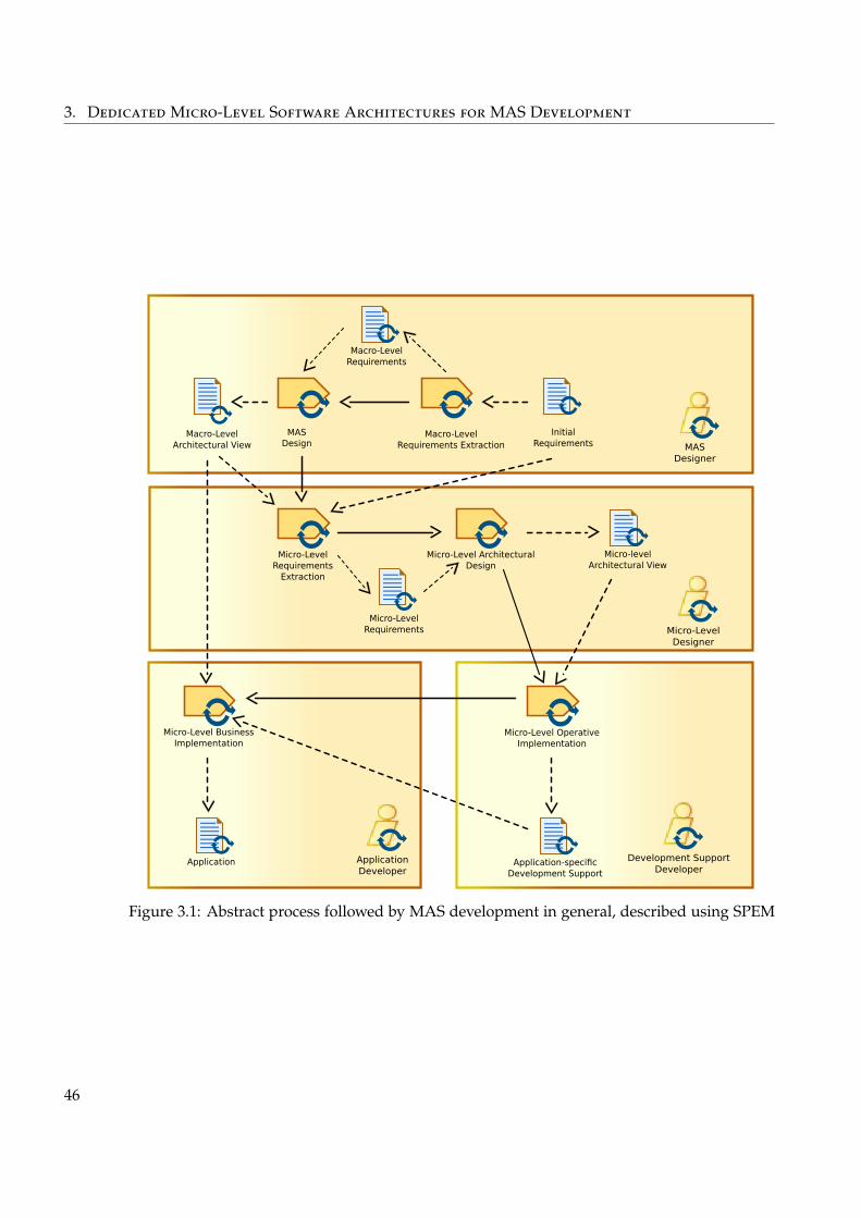
3. Dedicated Micro-Level Software Architectures for MAS Development
Macro-LevelRequirements
Micro-Level OperativeImplementation
Application-specificDevelopment Support
Development SupportDeveloper
ApplicationDeveloper
Micro-Level BusinessImplementation
Application
Micro-LevelRequirements
Micro-Level ArchitecturalDesign
Micro-levelArchitectural View
Micro-LevelRequirements
Extraction
Micro-LevelDesigner
Macro-LevelArchitectural View
InitialRequirements
MASDesign
Macro-LevelRequirements Extraction MAS
Designer
Figure 3.1: Abstract process followed by MAS development in general, described using SPEM
46
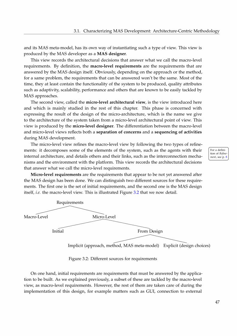
3.1. Characterizing MAS Development: Architecture-Centric Methodology
and its MAS meta-model, has its own way of instantiating such a type of view. This view isproduced by the MAS developer as a MAS designer.
This view records the architectural decisions that answer what we call the macro-levelrequirements. By definition, the macro-level requirements are the requirements that areanswered by the MAS design itself. Obviously, depending on the approach or the method,for a same problem, the requirements that can be answered won’t be the same. Most of thetime, they at least contain the functionality of the system to be produced, quality attributessuch as adaptivity, scalability, performance and others that are known to be easily tackled byMAS approaches.
The second view, called the micro-level architectural view, is the view introduced hereand which is mainly studied in the rest of this chapter. This phase is concerned withexpressing the result of the design of the micro-architecture, which is the name we giveto the architecture of the system taken from a micro-level architectural point of view. Thisview is produced by the micro-level designer. The differentiation between the macro-leveland micro-level views reflects both a separation of concerns and a sequencing of activitiesduring MAS development.
The micro-level view refines the macro-level view by following the two types of refine-ments: it decomposes some of the elements of the system, such as the agents with their For a defini-
tion of Refine-ment, see p. 8
For a defini-tion of Refine-ment, see p. 8internal architecture, and details others and their links, such as the interconnection mecha-
nisms and the environment with the platform. This view records the architectural decisionsthat answer what we call the micro-level requirements.
Micro-level requirements are the requirements that appear to be not yet answered afterthe MAS design has been done. We can distinguish two different sources for these require-ments. The first one is the set of initial requirements, and the second one is the MAS designitself, i.e. the macro-level view. This is illustrated Figure 3.2 that we now detail.
Requirements
Micro-Level
From Design
Explicit (design choices)Implicit (approach, method, MAS meta-model)
Initial
Macro-Level
Figure 3.2: Different sources for requirements
On one hand, initial requirements are requirements that must be answered by the applica-tion to be built. As we explained previously, a subset of these are tackled by the macro-levelview, as macro-level requirements. However, the rest of them are taken care of during theimplementation of this design, for example matters such as GUI, connection to external
47
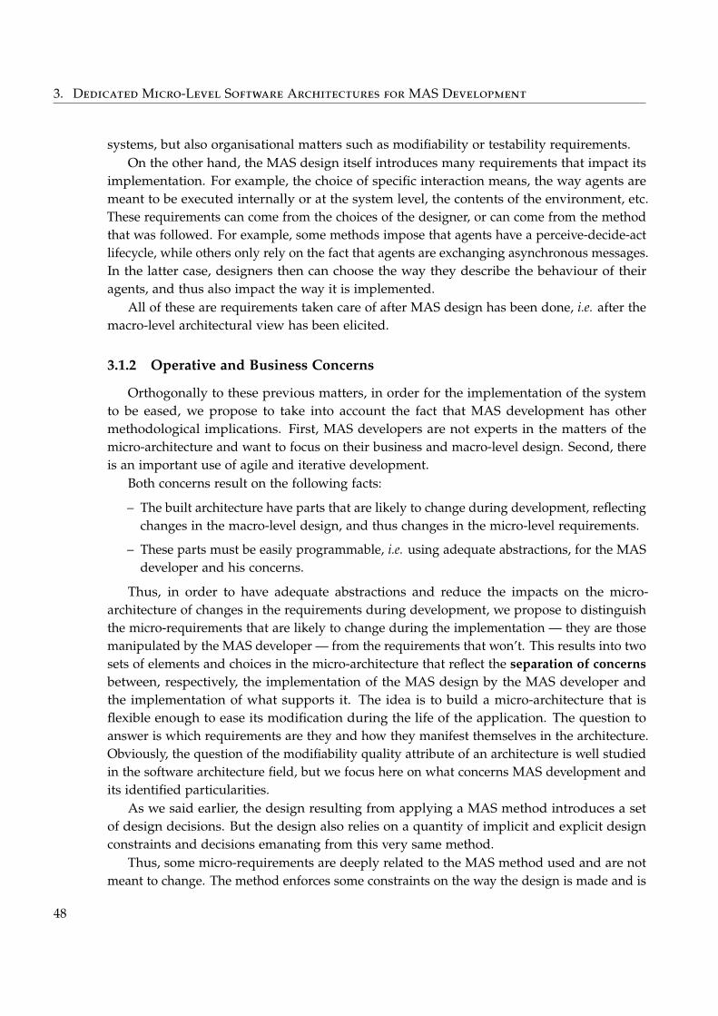
3. Dedicated Micro-Level Software Architectures for MAS Development
systems, but also organisational matters such as modifiability or testability requirements.On the other hand, the MAS design itself introduces many requirements that impact its
implementation. For example, the choice of specific interaction means, the way agents aremeant to be executed internally or at the system level, the contents of the environment, etc.These requirements can come from the choices of the designer, or can come from the methodthat was followed. For example, some methods impose that agents have a perceive-decide-actlifecycle, while others only rely on the fact that agents are exchanging asynchronous messages.In the latter case, designers then can choose the way they describe the behaviour of theiragents, and thus also impact the way it is implemented.
All of these are requirements taken care of after MAS design has been done, i.e. after themacro-level architectural view has been elicited.
3.1.2 Operative and Business Concerns
Orthogonally to these previous matters, in order for the implementation of the systemto be eased, we propose to take into account the fact that MAS development has othermethodological implications. First, MAS developers are not experts in the matters of themicro-architecture and want to focus on their business and macro-level design. Second, thereis an important use of agile and iterative development.
Both concerns result on the following facts:
– The built architecture have parts that are likely to change during development, reflectingchanges in the macro-level design, and thus changes in the micro-level requirements.
– These parts must be easily programmable, i.e. using adequate abstractions, for the MASdeveloper and his concerns.
Thus, in order to have adequate abstractions and reduce the impacts on the micro-architecture of changes in the requirements during development, we propose to distinguishthe micro-requirements that are likely to change during the implementation — they are thosemanipulated by the MAS developer — from the requirements that won’t. This results into twosets of elements and choices in the micro-architecture that reflect the separation of concernsbetween, respectively, the implementation of the MAS design by the MAS developer andthe implementation of what supports it. The idea is to build a micro-architecture that isflexible enough to ease its modification during the life of the application. The question toanswer is which requirements are they and how they manifest themselves in the architecture.Obviously, the question of the modifiability quality attribute of an architecture is well studiedin the software architecture field, but we focus here on what concerns MAS development andits identified particularities.
As we said earlier, the design resulting from applying a MAS method introduces a setof design decisions. But the design also relies on a quantity of implicit and explicit designconstraints and decisions emanating from this very same method.
Thus, some micro-requirements are deeply related to the MAS method used and are notmeant to change. The method enforces some constraints on the way the design is made and is
48
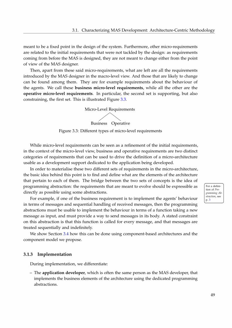
3.1. Characterizing MAS Development: Architecture-Centric Methodology
meant to be a fixed point in the design of the system. Furthermore, other micro-requirementsare related to the initial requirements that were not tackled by the design: as requirementscoming from before the MAS is designed, they are not meant to change either from the pointof view of the MAS designer.
Then, apart from these said micro-requirements, what are left are all the requirementsintroduced by the MAS designer in the macro-level view. And those that are likely to changecan be found among them. They are for example requirements about the behaviour ofthe agents. We call these business micro-level requirements, while all the other are theoperative micro-level requirements. In particular, the second set is supporting, but alsoconstraining, the first set. This is illustrated Figure 3.3.
Micro-Level Requirements
OperativeBusiness
Figure 3.3: Different types of micro-level requirements
While micro-level requirements can be seen as a refinement of the initial requirements,in the context of the micro-level view, business and operative requirements are two distinctcategories of requirements that can be used to drive the definition of a micro-architectureusable as a development support dedicated to the application being developed.
In order to materialise these two different sets of requirements in the micro-architecture,the basic idea behind this point is to find and define what are the elements of the architecturethat pertain to each of them. The bridge between the two sets of concepts is the idea ofprogramming abstraction: the requirements that are meant to evolve should be expressible as For a defini-
tion of Pro-gramming Ab-straction, seep. 3
For a defini-tion of Pro-gramming Ab-straction, seep. 3
directly as possible using some abstractions.For example, if one of the business requirement is to implement the agents’ behaviour
in terms of messages and sequential handling of received messages, then the programmingabstractions must be usable to implement the behaviour in terms of a function taking a newmessage as input, and must provide a way to send messages in its body. A stated constrainton this abstraction is that this function is called for every message, and that messages aretreated sequentially and indefinitely.
We show Section 3.4 how this can be done using component-based architectures and thecomponent model we propose.
3.1.3 Implementation
During implementation, we differentiate:
– The application developer, which is often the same person as the MAS developer, thatimplements the business elements of the architecture using the dedicated programmingabstractions.
49
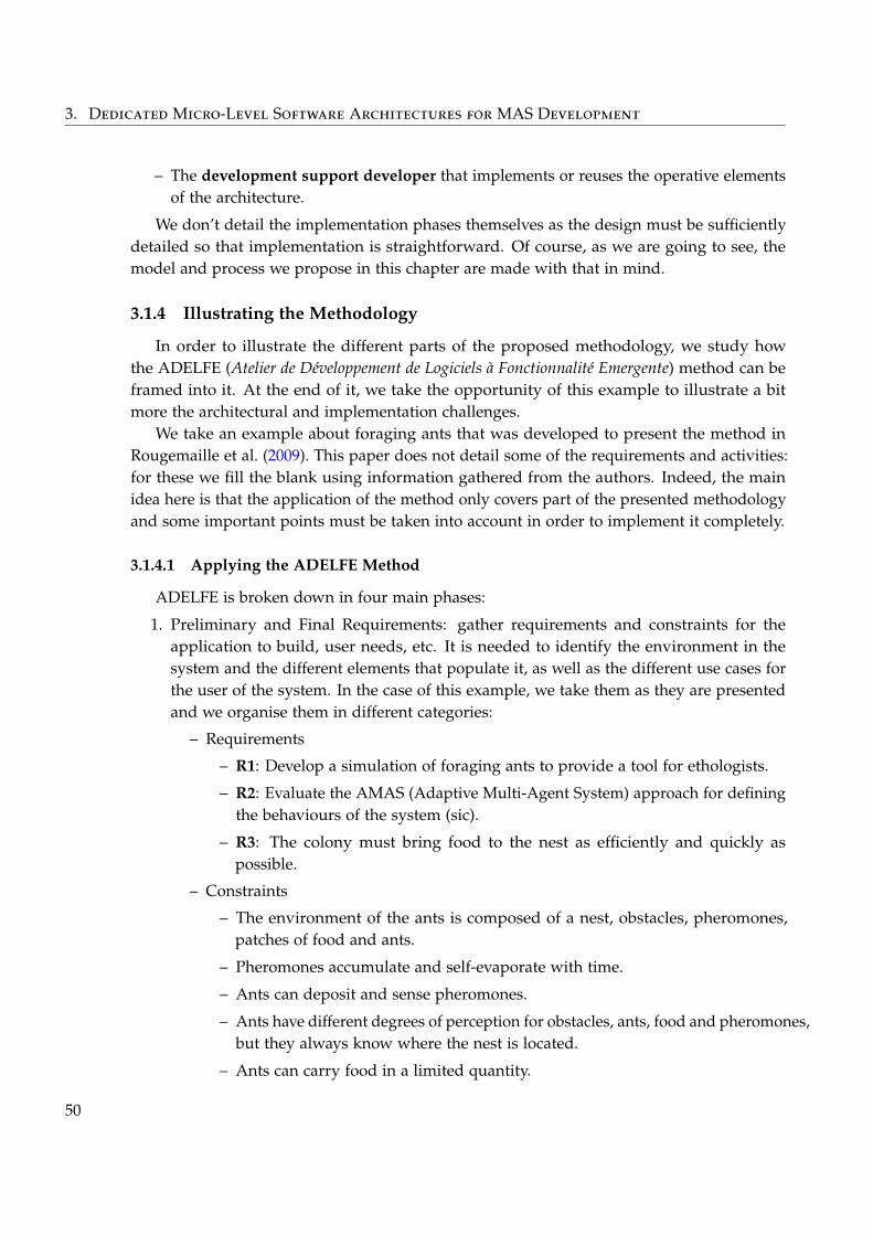
3. Dedicated Micro-Level Software Architectures for MAS Development
– The development support developer that implements or reuses the operative elementsof the architecture.
We don’t detail the implementation phases themselves as the design must be sufficientlydetailed so that implementation is straightforward. Of course, as we are going to see, themodel and process we propose in this chapter are made with that in mind.
3.1.4 Illustrating the Methodology
In order to illustrate the different parts of the proposed methodology, we study howthe ADELFE (Atelier de Développement de Logiciels à Fonctionnalité Emergente) method can beframed into it. At the end of it, we take the opportunity of this example to illustrate a bitmore the architectural and implementation challenges.
We take an example about foraging ants that was developed to present the method inRougemaille et al. (2009). This paper does not detail some of the requirements and activities:for these we fill the blank using information gathered from the authors. Indeed, the mainidea here is that the application of the method only covers part of the presented methodologyand some important points must be taken into account in order to implement it completely.
3.1.4.1 Applying the ADELFE Method
ADELFE is broken down in four main phases:
1. Preliminary and Final Requirements: gather requirements and constraints for theapplication to build, user needs, etc. It is needed to identify the environment in thesystem and the different elements that populate it, as well as the different use cases forthe user of the system. In the case of this example, we take them as they are presentedand we organise them in different categories:
– Requirements
– R1: Develop a simulation of foraging ants to provide a tool for ethologists.
– R2: Evaluate the AMAS (Adaptive Multi-Agent System) approach for definingthe behaviours of the system (sic).
– R3: The colony must bring food to the nest as efficiently and quickly aspossible.
– Constraints
– The environment of the ants is composed of a nest, obstacles, pheromones,patches of food and ants.
– Pheromones accumulate and self-evaporate with time.
– Ants can deposit and sense pheromones.
– Ants have different degrees of perception for obstacles, ants, food and pheromones,but they always know where the nest is located.
– Ants can carry food in a limited quantity.
50
3.1. Characterizing MAS Development: Architecture-Centric Methodology
– Ants can be a limited time outside and must rest at the nest.
– Ants explore the environment, avoid obstacles and harvest food when theyfind some.
– Use cases (those are not explicit in the paper)
– The state of simulation must be viewable in a GUI.
– Ants creation parameters can be changed by the user of the GUI.
– The simulation can be stopped, run step by step or accelerated.
– Entities
– Passive: obstacles, food and nest
– Active: ants, pheromones (evaporate)
– Environment
– Non-deterministic, accessible (its complete state is viewable for simulationpurpose), discrete (grid), dynamic (it is in particular modified by the ants andthe pheromones evaporate)
2. AMAS Analysis: determine if the AMAS approach is adapted to the problem andidentify which entities can be agents. We will just skip the details of this phase as it isnot interesting for us. This phase is also where we identify that ants are actually agentsas defined by the AMAS approach: conceptually distributed autonomous interactingentities with limited perception and range of action in an ever changing environmentand with an individual goal (harvest food).
3. Design: define the cooperative behaviour of the agents, here the ants, and the behaviourof the environment (for example pheromones evaporation). ADELFE uses a model-driven approach based on a DSML (Domain Specific Modelling Language) namedAMAS-ML and UML. The result of this phases is:
– A diagram called agent diagram that represents the internal structure of the agentsin terms of representations, characteristics, skills, aptitudes, actuators, sensorsand communication. The relations of this structure to the passive entities ofthe environment is also given (for example the “mandible actuator” of the antsis connected to “food”). At this point, already some information about howto implement and store data in the agents is given, but only from an internalpoint of view. Also, representations are implicitly meant to be inferred frompercepts, characteristics are intrinsic to the agents but depending on the problemcan be modified by the environment or the agent itself, skills and aptitudesare mechanisms that the agent can use internally while actuators, sensors andcommunication are meant to interact with the outside.
– A set of behavioural rules decomposed in standard behaviour and cooperativebehaviour. These rules are expressed in terms of the agent state at a given timeand the actions to undertake when its conditions are met. These conditions areexpressed using the previously presented available mechanisms of the agent.
51
3. Dedicated Micro-Level Software Architectures for MAS Development
– Sequence diagrams for detailing how the different mechanisms work and interactwith the environment and between agents.
4. Implementation: from the previously defined meta-models, the internal code structureof the agent is automatically generated, the behaviour too and only the differentelements of the internal structure such as the implementation of the representations,characteristics, skills, aptitudes, actuators, sensors and communication have to be done.Moreover, the environment itself, the GUI and the interaction means also have to beimplemented.
3.1.4.2 Framing ADELFE in the Methodology
Based on this, we can now discuss how ADELFE fits into the proposed methodology.The requirements, constraints and use cases presented are our initial requirements.A subset of them is clearly tackled by the method as the macro-requirements, in particular
the requirements R2 and R3, the constraints, the entities and the environment.Already we can spot some future micro-architectural requirements: the use cases and the
requirement R1. They of course have a partial impact on the MAS design itself, for examplefor defining which characteristics of the agents must be represented. For example, the factthat it is a simulation and that it must be viewable means that the environment has to beaccessible. But there is more to it, for example building the GUI and putting in place all theinfrastructure needed to access the state of the environment, the agents, etc.
The macro-level architectural view is clearly the result of ADELFE design step, althoughit contains too much details about implementation.
From this view, we can actually identify micro-level requirements that were not previouslydefined:
1. The AMAS approach dictates that agents actually have the following cycle: first percep-tion to update the representations from the percepts, then decision using the behaviourrules to choose which action to do, and then action to actually apply them.
2. Based on that, it means that the parts that are meant to be highly modified are theperception and the rules.
3. The agents have to be scheduled, one choice is to have a global clock and agent executionsynchronised, for example one point of synchronisation for each of the step of the agentcycle to ease concurrent modification of the environment.
4. There must be a way to access the internal state of the agents such as the quantity ofpheromones and food they have, or other internal informations useful for the systemobserver.
5. Inversely, there should be a way to modify some of the characteristics of the agents forthe ethologists to test different configurations.
6. The environment must implement all of the entities and make their state viewable (suchas the quantity of pheromone in one place).
52
3.1. Characterizing MAS Development: Architecture-Centric Methodology
7. The clock must also control pheromones evaporation, for example after agents haveacted and before they can perceive.
By making explicit all these micro-level requirements, we avoid taking care of importantrequirements too late. Of course, it mostly means that some requirements should actually bemade explicit by the MAS method used instead of staying implicit like that.
In terms of business requirements, for the developer of the application, it seems the secondmicro-level requirement is of first importance. The implementation and modification of theseparts must be easy.
The micro-level architectural view can then be defined based on that information. Thepaper does not detail so much the equivalent of this view, but in practice the implementationfor the managing the environment as well as the interconnection mechanisms were doneby hand. On the other hand, the structure of the agent is automatically generated as wellas the code for the rules. This last point concurs with the fact it is one of the businessrequirements. By exploiting code generation, this illustrates how iterations between designand implementation can happen, while the operative parts of the micro-architecture don’tchange.
3.1.4.3 Illustrating the Technical Challenges
The identified micro-level requirements shows the complexity in implementing all theinterconnections existing between the agents of the system and the runtime platform, inparticular the environment managing the pheromones. In particular, a point worth noticingis the interdependencies that exist between the interaction mean to move and the interactionmean to deposit pheromones. Indeed, the latter relies on the position of the agent toimplement pheromone depositing. At implementation time, it could first mean to have themimplemented together, which doesn’t promote reuse, since the move interaction mean couldbe used alone. It could also mean to implement the clear separation of concerns between thetwo in the agents (since the position is proper to each agent) and in the environment (sincethe pheromones are deposited in it).
Such questions also arise for visualising agents and their environment, or for the depen-dencies that can exist between pheromones evaporation and scheduling of the system.
There is thus needs to manage such complexity and to explicit dependencies betweeninteraction means and more generally for all the interconnection mechanisms. And theseneeds must be answered both at the agent and platform levels, for mechanisms that existin-between the two, that must be reusable and composed together easily. This is tackled bythe component model we present next.
3.1.5 Conclusion on the Methodology
This methodology is meant to be instantiated by existing methods for MAS development.Current methods mostly focus on the macro-level architectural view, which is not surprising
53
3. Dedicated Micro-Level Software Architectures for MAS Development
since this is the main challenge in the MAS field, because these methods mostly do not take acomplete architectural stance and of course also because this distinction wasn’t coined before.
We now present a component model to ease the design and implementation of the micro-level architectural view and then we continue with a method that relies on this model toguide this design.
3.2 Component-Based Micro-Level Architectures
In order to design and implement the micro-architecture of MASs, we propose to use acomponent model that answers the technical challenges identified Chapter 2. We recall thesehere:
– Define and implement interconnection mechanisms for connecting agents to the runtimeplatform and vice-versa.
– Define and implement types of agents with specific internal architecture and intercon-nected to the runtime platform.
– Provide dynamic creation of instance of these types of agents and their dynamicconnection and initialisation.
– Make the reuse of such interconnection mechanisms and architectures easy.
At runtime, the differentiation between the agents and the runtime platform executingthem is of first importance: the macro-architectural view is made of agents interacting togetherthrough an environment, and when refining this view with the micro-architectural view,it is necessary to keep this separation explicit in order to retain the property of the MASdesign in terms of interaction, autonomy, dynamics, etc. As we highlighted in the previouschapter, this has an impact on the way to organise the micro-architecture so that the dynamiccreation and execution of the agents is possible. In terms of runtime entities, each agent hasits own architecture: they are instantiated by and connected to the platform architecture sothat interactions between the agents and the environment and between them are possible.
Some ideas are given about how this model is used to support MAS development, but thedetails are presented Section 3.4 on the SpEArAF method.
This section presents the SpeAD (Species-based Architectural Design) component modelincrementally: we start by defining a base component model — named SpeAD−— resemblingexisting component model, and then we introduce on top of it the specific abstractionsproposed in this work. This has two advantages: first this eases the presentation of the newconcepts, second this helps to easily identify the novelty in the contribution.
The general plan followed to present each of the aspects of the model is as follow. First, weFor a presen-tation of therelations be-tween Com-ponent Mod-els, ADLs andComponentContainer, seep. 6
For a presen-tation of therelations be-tween Com-ponent Mod-els, ADLs andComponentContainer, seep. 6
present how elements are described used SpeADL (Species-based Architectural DescriptionLanguage), an ADL we propose. Second, we present how these elements can be implementedusing the Java programming language by relying on code generated from the ADL. Finally,we present how these elements can be instantiated and are executed by the componentcontainer, which is completely constituted of the generated code.
54
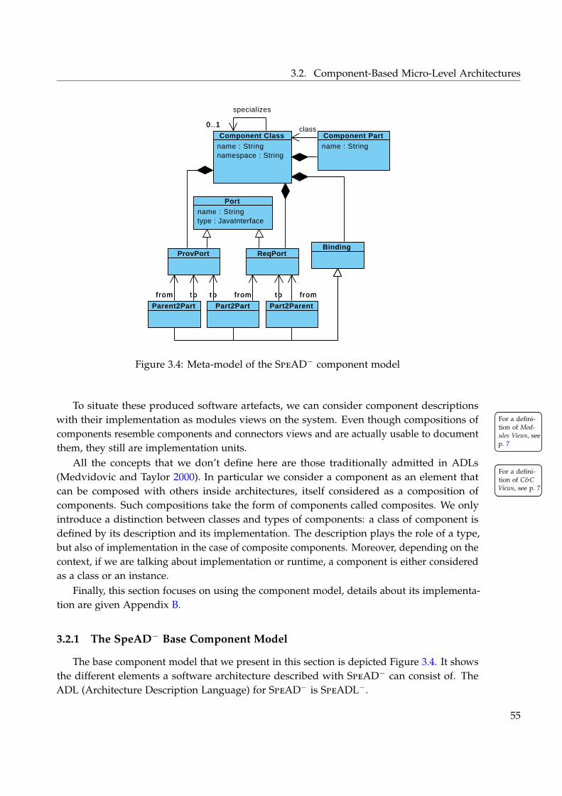
3.2. Component-Based Micro-Level Architectures
name : String namespace : String
Component Class name : String
Component Part
ProvPort ReqPort
name : String type : JavaInterface
Port
Binding
Part2Part Part2ParentParent2Part
specializes
0..1
f romt o t ot o f romfromt ofrom
0..1
t o
class
t of romfrom
Visual Paradigm for UML Community Edition [not for commercial use]
Figure 3.4: Meta-model of the SpeAD− component model
To situate these produced software artefacts, we can consider component descriptionswith their implementation as modules views on the system. Even though compositions of For a defini-
tion of Mod-ules Views, seep. 7
For a defini-tion of Mod-ules Views, seep. 7
components resemble components and connectors views and are actually usable to document
For a defini-tion of C&CViews, see p. 7
For a defini-tion of C&CViews, see p. 7
them, they still are implementation units.All the concepts that we don’t define here are those traditionally admitted in ADLs
(Medvidovic and Taylor 2000). In particular we consider a component as an element thatcan be composed with others inside architectures, itself considered as a composition ofcomponents. Such compositions take the form of components called composites. We onlyintroduce a distinction between classes and types of components: a class of component isdefined by its description and its implementation. The description plays the role of a type,but also of implementation in the case of composite components. Moreover, depending on thecontext, if we are talking about implementation or runtime, a component is either consideredas a class or an instance.
Finally, this section focuses on using the component model, details about its implementa-tion are given Appendix B.
3.2.1 The SpeAD− Base Component Model
The base component model that we present in this section is depicted Figure 3.4. It showsthe different elements a software architecture described with SpeAD− can consist of. TheADL (Architecture Description Language) for SpeAD− is SpeADL−.
55
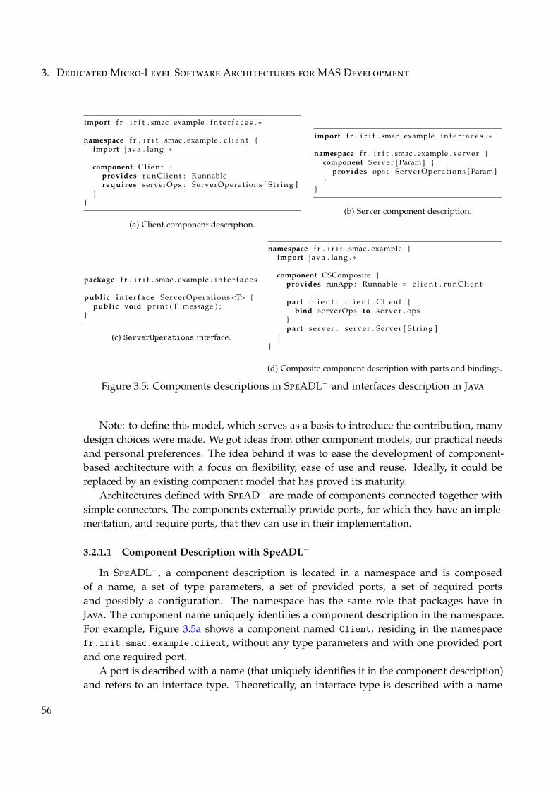
3. Dedicated Micro-Level Software Architectures for MAS Development
import f r . i r i t . smac . example . i n t e r f a c e s .∗
namespace f r . i r i t . smac . example . c l i e n t {import j ava . lang .∗
component C l i e n t {provides runCl ient : Runnablerequires serverOps : ServerOperat ions [ S t r i n g ]
}}
(a) Client component description.
import f r . i r i t . smac . example . i n t e r f a c e s .∗
namespace f r . i r i t . smac . example . server {component Server [ Param ] {
provides ops : ServerOperat ions [ Param ]}
}
(b) Server component description.
package f r . i r i t . smac . example . i n t e r f a c e s
public i n t e r f a c e ServerOperations <T> {public void p r i n t ( T message ) ;
}
(c) ServerOperations interface.
namespace f r . i r i t . smac . example {import j ava . lang .∗
component CSComposite {provides runApp : Runnable = c l i e n t . runCl ient
part c l i e n t : c l i e n t . C l i e n t {bind serverOps to server . ops
}part server : server . Server [ S t r i n g ]
}}
(d) Composite component description with parts and bindings.
Figure 3.5: Components descriptions in SpeADL− and interfaces description in Java
Note: to define this model, which serves as a basis to introduce the contribution, manydesign choices were made. We got ideas from other component models, our practical needsand personal preferences. The idea behind it was to ease the development of component-based architecture with a focus on flexibility, ease of use and reuse. Ideally, it could bereplaced by an existing component model that has proved its maturity.
Architectures defined with SpeAD− are made of components connected together withsimple connectors. The components externally provide ports, for which they have an imple-mentation, and require ports, that they can use in their implementation.
3.2.1.1 Component Description with SpeADL−
In SpeADL−, a component description is located in a namespace and is composedof a name, a set of type parameters, a set of provided ports, a set of required portsand possibly a configuration. The namespace has the same role that packages have inJava. The component name uniquely identifies a component description in the namespace.For example, Figure 3.5a shows a component named Client, residing in the namespacefr.irit.smac.example.client, without any type parameters and with one provided portand one required port.
A port is described with a name (that uniquely identifies it in the component description)and refers to an interface type. Theoretically, an interface type is described with a name
56
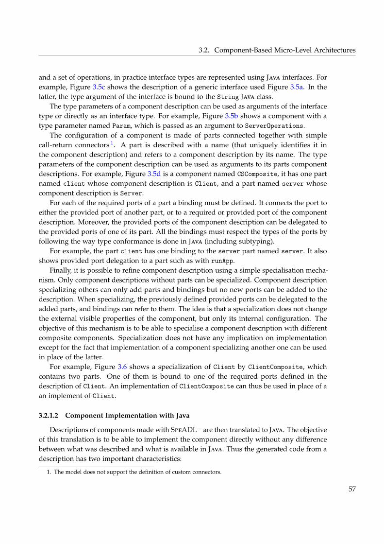
3.2. Component-Based Micro-Level Architectures
and a set of operations, in practice interface types are represented using Java interfaces. Forexample, Figure 3.5c shows the description of a generic interface used Figure 3.5a. In thelatter, the type argument of the interface is bound to the String Java class.
The type parameters of a component description can be used as arguments of the interfacetype or directly as an interface type. For example, Figure 3.5b shows a component with atype parameter named Param, which is passed as an argument to ServerOperations.
The configuration of a component is made of parts connected together with simplecall-return connectors 1. A part is described with a name (that uniquely identifies it inthe component description) and refers to a component description by its name. The typeparameters of the component description can be used as arguments to its parts componentdescriptions. For example, Figure 3.5d is a component named CSComposite, it has one partnamed client whose component description is Client, and a part named server whosecomponent description is Server.
For each of the required ports of a part a binding must be defined. It connects the port toeither the provided port of another part, or to a required or provided port of the componentdescription. Moreover, the provided ports of the component description can be delegated tothe provided ports of one of its part. All the bindings must respect the types of the ports byfollowing the way type conformance is done in Java (including subtyping).
For example, the part client has one binding to the server part named server. It alsoshows provided port delegation to a part such as with runApp.
Finally, it is possible to refine component description using a simple specialisation mecha-nism. Only component descriptions without parts can be specialized. Component descriptionspecializing others can only add parts and bindings but no new ports can be added to thedescription. When specializing, the previously defined provided ports can be delegated to theadded parts, and bindings can refer to them. The idea is that a specialization does not changethe external visible properties of the component, but only its internal configuration. Theobjective of this mechanism is to be able to specialise a component description with differentcomposite components. Specialization does not have any implication on implementationexcept for the fact that implementation of a component specializing another one can be usedin place of the latter.
For example, Figure 3.6 shows a specialization of Client by ClientComposite, whichcontains two parts. One of them is bound to one of the required ports defined in thedescription of Client. An implementation of ClientComposite can thus be used in place of aan implement of Client.
3.2.1.2 Component Implementation with Java
Descriptions of components made with SpeADL− are then translated to Java. The objectiveof this translation is to be able to implement the component directly without any differencebetween what was described and what is available in Java. Thus the generated code from adescription has two important characteristics:
1. The model does not support the definition of custom connectors.
57
3. Dedicated Micro-Level Software Architectures for MAS Development
component ClientComposite s p e c i a l i z e s C l i e n t {provides runCl ient : Runnable = one . p1
part one : ComponentOne {bind p2 to two . p1
}part two : ComponentTwo {
bind p2 toThis serverOps}
}
component ComponentOne {provides p1 : Runnablerequires p2 : Runnable
}
component ComponentTwo {provides p1 : Runnablerequires p2 : ServerOperat ions [ S t r i n g ]
}
Figure 3.6: Component specialization in SpeADL−
– It has the exact same semantics 2 than the description and acts as an invisible bridgebetween description and implementation.
– It eases the implementation by well integrating it into the Java language and exploitingthe type system to catch errors as early as possible.
In this section, we only describe what is needed to understand how components areimplemented. The details of the internal working of the component model and of thetransformation from SpeADL (and thus SpeADL−) to Java is described Appendix B.
Each component description becomes a Java class, that we call the description class, withthe same name, type parameters and namespace (package in Java). The general idea behindthis translation is that the implementation provides a set of methods. These methods returninstances of the implementation of the different elements of a component (parts and ports).These instances are used to construct an actual instance of the component.
In the description class, each of the provided ports (that are not already delegated toanother port) is translated to an abstract method without parameters named after the portand prefixed by make_. The method returns an instance of the type of the port. Moreover,to access the provided ports from within the implementation, a protected method namedafter the port and returning an instance of the type of the port is also present. To accessthe required ports, each of them is translated to a protected method without parametersnamed after the port and returning an instance of the type of the port. Each of the parts istranslated to an abstract method without parameters named after the part and prefixed bymake_. It returns an instance of an implementation of the component description of the part.Moreover, to access the parts from within the implementation, a protected method withoutparameters named after the part and returning an instance of the Component interface of itsclass description is present. Finally, the description class provides a method (which is notabstract) named start that can be overridden to implement initialisation logic.
2. Even though this semantics is limited to the structure and the types of the ports.
58
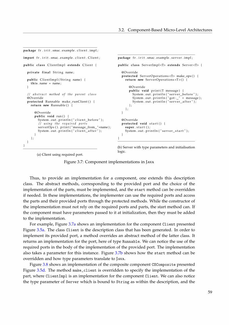
3.2. Component-Based Micro-Level Architectures
package f r . i r i t . smac . example . c l i e n t . impl ;
import f r . i r i t . smac . example . c l i e n t . C l i e n t ;
public c l a s s ClientImpl extends C l i e n t {
private f i n a l S t r i n g name ;
public ClientImpl ( S t r i n g name) {t h i s . name = name ;
}
/ / a b s t r a c t method o f t h e p a r e n t c l a s s@Overrideprotected Runnable make_runClient ( ) {
return new Runnable ( ) {
@Overridepublic void run ( ) {
System . out . p r i n t l n ( " c l i e n t before " ) ;/ / us ing t h e r e q u i r e d p o r t sserverOps ( ) . p r i n t ( " message from "+name ) ;System . out . p r i n t l n ( " c l i e n t a f t e r " ) ;
}} ;
}}
(a) Client using required port.
package f r . i r i t . smac . example . server . impl ;
public c l a s s ServerImpl <T> extends Server <T> {
@Overrideprotected ServerOperations <T> make_ops ( ) {
return new ServerOperations <T> ( ) {
@Overridepublic void p r i n t ( T message ) {
System . out . p r i n t l n ( " server before " ) ;System . out . p r i n t l n ( " got : " + message ) ;System . out . p r i n t l n ( " server a f t e r " ) ;
} ;} ;
}
@Overrideprotected void s t a r t ( ) {
super . s t a r t ( ) ;System . out . p r i n t l n ( " server s t a r t " ) ;
}}
(b) Server with type parameters and initialisationlogic.
Figure 3.7: Component implementations in Java
Thus, to provide an implementation for a component, one extends this descriptionclass. The abstract methods, corresponding to the provided port and the choice of theimplementation of the parts, must be implemented, and the start method can be overriddenif needed. In these implementations, the implementer can use the required ports and accessthe parts and their provided ports through the protected methods. While the constructor ofthe implementation must not rely on the required ports and parts, the start method can. Ifthe component must have parameters passed to it at initialization, then they must be addedto the implementation.
For example, Figure 3.7a shows an implementation for the component Client presentedFigure 3.5a. The class Client is the description class that has been generated. In order toimplement its provided port, a method overrides an abstract method of the latter class. Itreturns an implementation for the port, here of type Runnable. We can notice the use of therequired ports in the body of the implementation of the provided port. The implementationalso takes a parameter for this instance. Figure 3.7b shows how the start method can beoverridden and how type parameters translate to Java.
Figure 3.8 shows an implementation of the composite component CSComposite presentedFigure 3.5d. The method make_client is overridden to specify the implementation of thepart, where ClientImpl is an implementation for the component Client. We can also noticethe type parameter of Server which is bound to String as within the description, and the
59
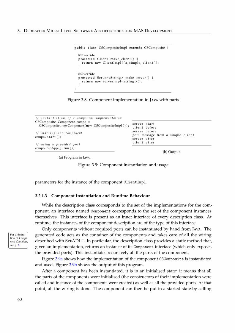
3. Dedicated Micro-Level Software Architectures for MAS Development
public c l a s s CSCompositeImpl extends CSComposite {
@Overrideprotected C l i e n t make_cl ient ( ) {
return new ClientImpl ( " a simple c l i e n t " ) ;}
@Overrideprotected Server <Str ing > make_server ( ) {
return new ServerImpl <Str ing > ( ) ;}
}
Figure 3.8: Component implementation in Java with parts
/ / i n s t a n t i a t i o n o f a component i m p l e m e n t a t i o nCSComposite . Component compo =
CSComposite . newComponent (new CSCompositeImpl ( ) ) ;
/ / s t a r t i n g t h e componentcompo . s t a r t ( ) ;
/ / us ing a p r o v i d e d p o r tcompo . runApp ( ) . run ( ) ;
(a) Program in Java.
server s t a r tc l i e n t beforeserver beforegot : message from a simple c l i e n tserver a f t e rc l i e n t a f t e r
(b) Output.
Figure 3.9: Component instantiation and usage
parameters for the instance of the component ClientImpl.
3.2.1.3 Component Instantiation and Runtime Behaviour
While the description class corresponds to the set of the implementations for the com-ponent, an interface named Component corresponds to the set of the component instancesthemselves. This interface is present as an inner interface of every description class. Atruntime, the instances of the component description are of the type of this interface.
Only components without required ports can be instantiated by hand from Java. Thegenerated code acts as the container of the components and takes care of all the wiringFor a defini-
tion of Compo-nent Container,see p. 6
For a defini-tion of Compo-nent Container,see p. 6
described with SpeADL−. In particular, the description class provides a static method that,given an implementation, returns an instance of its Component interface (which only exposesthe provided ports). This instantiates recursively all the parts of the component.
Figure 3.9a shows how the implementation of the component CSComposite is instantiatedand used. Figure 3.9b shows the output of this program.
After a component has been instantiated, it is in an initialised state: it means that allthe parts of the components were initialised (the constructors of their implementation werecalled and instance of the components were created) as well as all the provided ports. At thatpoint, all the wiring is done. The component can then be put in a started state by calling
60
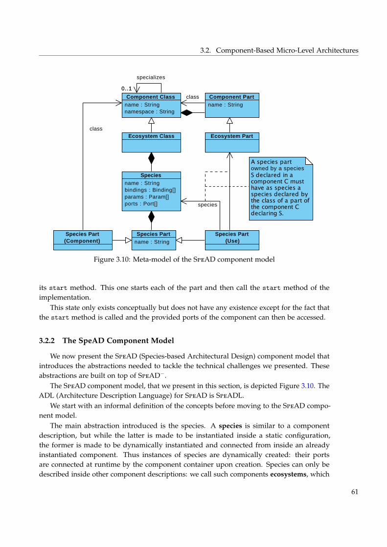
3.2. Component-Based Micro-Level Architectures
name : String namespace : String
Component Class name : String
Component Part
name : String bindings : Binding[] params : Param[] ports : Port[]
Species
name : String
Species PartSpecies Part(Component)
Species Part(Use)
species
Ecosystem Class Ecosystem Part
owned by a species
0..1
class
class
specializes
0..1
Visual Paradigm for UML Community Edition [not for commercial use]
Figure 3.10: Meta-model of the SpeAD component model
its start method. This one starts each of the part and then call the start method of theimplementation.
This state only exists conceptually but does not have any existence except for the fact thatthe start method is called and the provided ports of the component can then be accessed.
3.2.2 The SpeAD Component Model
We now present the SpeAD (Species-based Architectural Design) component model thatintroduces the abstractions needed to tackle the technical challenges we presented. Theseabstractions are built on top of SpeAD−.
The SpeAD component model, that we present in this section, is depicted Figure 3.10. TheADL (Architecture Description Language) for SpeAD is SpeADL.
We start with an informal definition of the concepts before moving to the SpeAD compo-nent model.
The main abstraction introduced is the species. A species is similar to a componentdescription, but while the latter is made to be instantiated inside a static configuration,the former is made to be dynamically instantiated and connected from inside an alreadyinstantiated component. Thus instances of species are dynamically created: their portsare connected at runtime by the component container upon creation. Species can only bedescribed inside other component descriptions: we call such components ecosystems, which
61
3. Dedicated Micro-Level Software Architectures for MAS Development
extend components of SpeAD−. They are the only one capable of creating instances of thespecies they declare. The species instances then exist inside the instance of these ecosystems.
In the context of MASs, type of agents are described using species, while their ecosystemacts as their runtime platform. More on this matter is given Section 3.4 about the SpEArAFmethod. However, using this definition of species is not enough to cover the needs thecontribution must answer. Instances of species must be connected to their ecosystem: weintroduce an additional concept that realises such connection.
In order to understand this concept, we first present a simplified idea of its use andpurpose. The idea is that when a species is instantiated, it is desired that its instance isconnected to its ecosystem. At runtime, for the instance to be correctly connected, two thingsare important:
– The elements connecting the instance to its ecosystem must already exist in the ecosys-tem.
– These elements have to instantiate a part of themselves within the instance in order toestablish a link between the two.
This element is then composed of two different “sides”: one that is instantiated within theecosystem, and one that is instantiated for every instance of the species described in theecosystem.
In the context of MASs, interaction mechanisms and other links between an agent andits platform can be realised using such “two-sides” elements. For example, a mechanism fordepositing pheromones as has a side in the ecosystem for managing the pheromones andtheir evaporation, and a side in the agent for handling its personal stock of pheromones. Theside in the agent also has to be aware of the location of the agents in a virtual space, etc.The same is possible for operative interconnection mechanisms between the agents and theirplatform, such as GUIs for visualising agents, or global control of the execution of the agents.Such other examples are given in the rest of this section as well as Section 3.3.
Back to SpeAD, we can model such “two-sides” elements by using the concepts of speciesand ecosystem in a recursive way. In order to do so, we propose that when a species isdefined, it can “use” species of one of the parts of its declaring ecosystem. This means thatwhen an instance of a species is dynamically created, instances of all the species it uses arealso dynamically instantiated recursively.
Thus, even though the term species was historically introduced as a mean to characterise atype of agent, it does not only refer to that idea. It must also be noted that the term ecosystemused here should not be mixed up with the concepts of software ecosystem (Bosch 2009): evenif they share an ecological origin, our ecosystem is the product of the development and notthe context into which the development happens and is constrained. From this point ofview, the term ecosystem is well adapted to characterise the entity that defines species and isresponsible of maintaining their instances “alive”.
Based on these definitions, we now detail how species and their connections are describedin ecosystem, how they are implemented and how they are instantiated and executed.
62
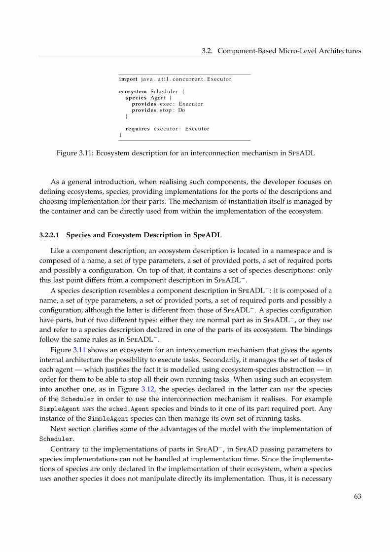
3.2. Component-Based Micro-Level Architectures
import j ava . u t i l . concurrent . Executor
ecosystem Scheduler {species Agent {
provides exec : Executorprovides stop : Do
}
requires executor : Executor}
Figure 3.11: Ecosystem description for an interconnection mechanism in SpeADL
As a general introduction, when realising such components, the developer focuses ondefining ecosystems, species, providing implementations for the ports of the descriptions andchoosing implementation for their parts. The mechanism of instantiation itself is managed bythe container and can be directly used from within the implementation of the ecosystem.
3.2.2.1 Species and Ecosystem Description in SpeADL
Like a component description, an ecosystem description is located in a namespace and iscomposed of a name, a set of type parameters, a set of provided ports, a set of required portsand possibly a configuration. On top of that, it contains a set of species descriptions: onlythis last point differs from a component description in SpeADL−.
A species description resembles a component description in SpeADL−: it is composed of aname, a set of type parameters, a set of provided ports, a set of required ports and possibly aconfiguration, although the latter is different from those of SpeADL−. A species configurationhave parts, but of two different types: either they are normal part as in SpeADL−, or they useand refer to a species description declared in one of the parts of its ecosystem. The bindingsfollow the same rules as in SpeADL−.
Figure 3.11 shows an ecosystem for an interconnection mechanism that gives the agentsinternal architecture the possibility to execute tasks. Secondarily, it manages the set of tasks ofeach agent — which justifies the fact it is modelled using ecosystem-species abstraction — inorder for them to be able to stop all their own running tasks. When using such an ecosysteminto another one, as in Figure 3.12, the species declared in the latter can use the speciesof the Scheduler in order to use the interconnection mechanism it realises. For exampleSimpleAgent uses the sched.Agent species and binds to it one of its part required port. Anyinstance of the SimpleAgent species can then manage its own set of running tasks.
Next section clarifies some of the advantages of the model with the implementation ofScheduler.
Contrary to the implementations of parts in SpeAD−, in SpeAD passing parameters tospecies implementations can not be handled at implementation time. Since the implementa-tions of species are only declared in the implementation of their ecosystem, when a speciesuses another species it does not manipulate directly its implementation. Thus, it is necessary
63
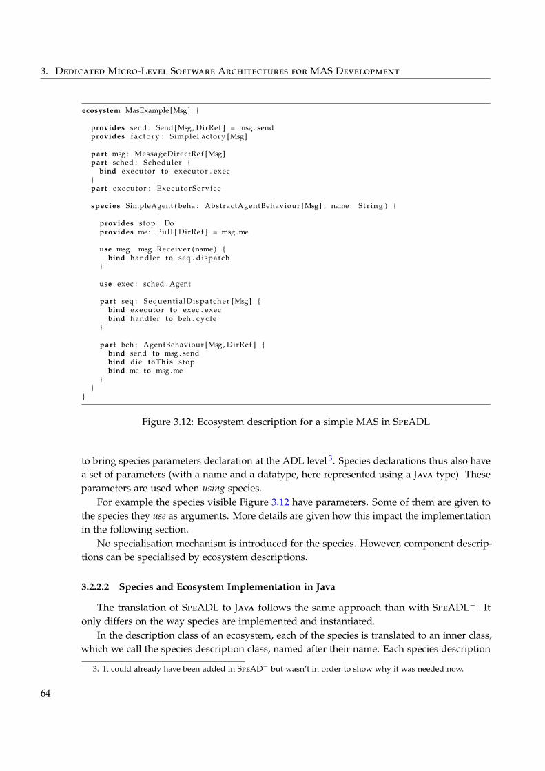
3. Dedicated Micro-Level Software Architectures for MAS Development
ecosystem MasExample [Msg] {
provides send : Send [Msg , DirRef ] = msg . sendprovides f a c t o r y : SimpleFactory [Msg]
part msg : MessageDirectRef [Msg]part sched : Scheduler {
bind executor to executor . exec}part executor : ExecutorServ ice
species SimpleAgent ( beha : AbstractAgentBehaviour [Msg] , name : S t r i n g ) {
provides stop : Doprovides me: Pul l [ DirRef ] = msg .me
use msg : msg . Receiver (name) {bind handler to seq . dispatch
}
use exec : sched . Agent
part seq : Sequent ia lDispatcher [Msg] {bind executor to exec . execbind handler to beh . c y c l e
}
part beh : AgentBehaviour [Msg , DirRef ] {bind send to msg . sendbind die toThis stopbind me to msg .me
}}
}
Figure 3.12: Ecosystem description for a simple MAS in SpeADL
to bring species parameters declaration at the ADL level 3. Species declarations thus also havea set of parameters (with a name and a datatype, here represented using a Java type). Theseparameters are used when using species.
For example the species visible Figure 3.12 have parameters. Some of them are given tothe species they use as arguments. More details are given how this impact the implementationin the following section.
No specialisation mechanism is introduced for the species. However, component descrip-tions can be specialised by ecosystem descriptions.
3.2.2.2 Species and Ecosystem Implementation in Java
The translation of SpeADL to Java follows the same approach than with SpeADL−. Itonly differs on the way species are implemented and instantiated.
In the description class of an ecosystem, each of the species is translated to an inner class,which we call the species description class, named after their name. Each species description
3. It could already have been added in SpeAD− but wasn’t in order to show why it was needed now.
64
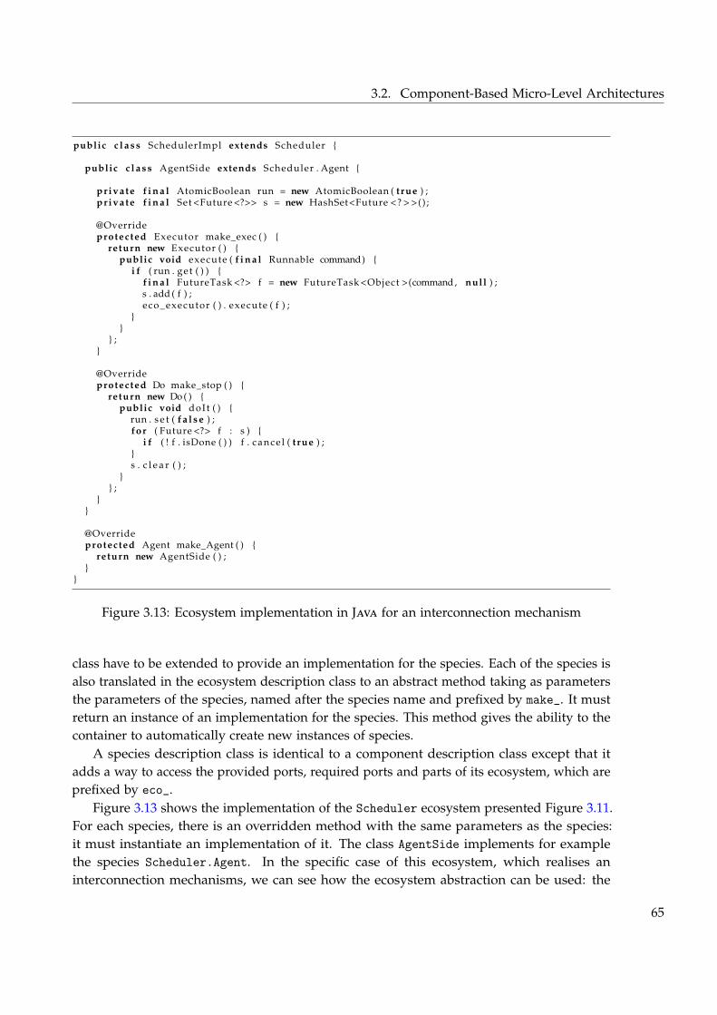
3.2. Component-Based Micro-Level Architectures
public c l a s s SchedulerImpl extends Scheduler {
public c l a s s AgentSide extends Scheduler . Agent {
private f i n a l AtomicBoolean run = new AtomicBoolean ( t rue ) ;private f i n a l Set <Future <?>> s = new HashSet<Future <? > >() ;
@Overrideprotected Executor make_exec ( ) {
return new Executor ( ) {public void execute ( f i n a l Runnable command) {
i f ( run . get ( ) ) {f i n a l FutureTask <?> f = new FutureTask <Object >(command, null ) ;s . add ( f ) ;eco_executor ( ) . execute ( f ) ;
}}
} ;}
@Overrideprotected Do make_stop ( ) {
return new Do ( ) {public void doIt ( ) {
run . s e t ( f a l s e ) ;for ( Future <?> f : s ) {
i f ( ! f . isDone ( ) ) f . cance l ( t rue ) ;}s . c l e a r ( ) ;
}} ;
}}
@Overrideprotected Agent make_Agent ( ) {
return new AgentSide ( ) ;}
}
Figure 3.13: Ecosystem implementation in Java for an interconnection mechanism
class have to be extended to provide an implementation for the species. Each of the species isalso translated in the ecosystem description class to an abstract method taking as parametersthe parameters of the species, named after the species name and prefixed by make_. It mustreturn an instance of an implementation for the species. This method gives the ability to thecontainer to automatically create new instances of species.
A species description class is identical to a component description class except that itadds a way to access the provided ports, required ports and parts of its ecosystem, which areprefixed by eco_.
Figure 3.13 shows the implementation of the Scheduler ecosystem presented Figure 3.11.For each species, there is an overridden method with the same parameters as the species:it must instantiate an implementation of it. The class AgentSide implements for examplethe species Scheduler.Agent. In the specific case of this ecosystem, which realises aninterconnection mechanisms, we can see how the ecosystem abstraction can be used: the
65
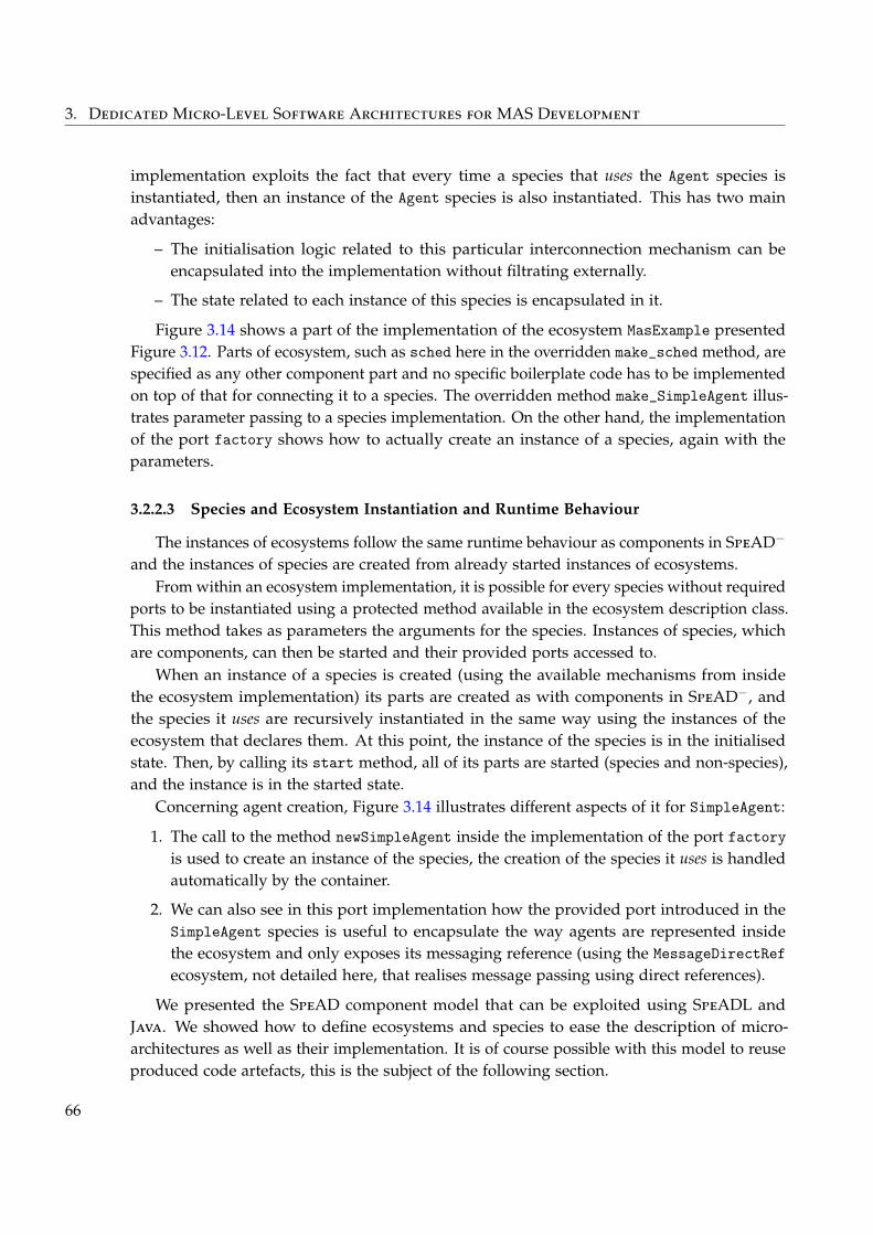
3. Dedicated Micro-Level Software Architectures for MAS Development
implementation exploits the fact that every time a species that uses the Agent species isinstantiated, then an instance of the Agent species is also instantiated. This has two mainadvantages:
– The initialisation logic related to this particular interconnection mechanism can beencapsulated into the implementation without filtrating externally.
– The state related to each instance of this species is encapsulated in it.
Figure 3.14 shows a part of the implementation of the ecosystem MasExample presentedFigure 3.12. Parts of ecosystem, such as sched here in the overridden make_sched method, arespecified as any other component part and no specific boilerplate code has to be implementedon top of that for connecting it to a species. The overridden method make_SimpleAgent illus-trates parameter passing to a species implementation. On the other hand, the implementationof the port factory shows how to actually create an instance of a species, again with theparameters.
3.2.2.3 Species and Ecosystem Instantiation and Runtime Behaviour
The instances of ecosystems follow the same runtime behaviour as components in SpeAD−
and the instances of species are created from already started instances of ecosystems.From within an ecosystem implementation, it is possible for every species without required
ports to be instantiated using a protected method available in the ecosystem description class.This method takes as parameters the arguments for the species. Instances of species, whichare components, can then be started and their provided ports accessed to.
When an instance of a species is created (using the available mechanisms from insidethe ecosystem implementation) its parts are created as with components in SpeAD−, andthe species it uses are recursively instantiated in the same way using the instances of theecosystem that declares them. At this point, the instance of the species is in the initialisedstate. Then, by calling its start method, all of its parts are started (species and non-species),and the instance is in the started state.
Concerning agent creation, Figure 3.14 illustrates different aspects of it for SimpleAgent:
1. The call to the method newSimpleAgent inside the implementation of the port factoryis used to create an instance of the species, the creation of the species it uses is handledautomatically by the container.
2. We can also see in this port implementation how the provided port introduced in theSimpleAgent species is useful to encapsulate the way agents are represented insidethe ecosystem and only exposes its messaging reference (using the MessageDirectRefecosystem, not detailed here, that realises message passing using direct references).
We presented the SpeAD component model that can be exploited using SpeADL andJava. We showed how to define ecosystems and species to ease the description of micro-architectures as well as their implementation. It is of course possible with this model to reuseproduced code artefacts, this is the subject of the following section.
66
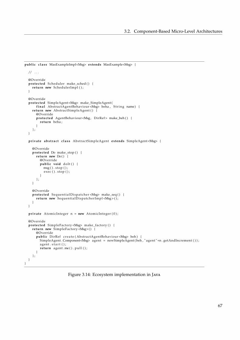
3.2. Component-Based Micro-Level Architectures
public c l a s s MasExampleImpl<Msg> extends MasExample<Msg> {
/ / . . .
@Overrideprotected Scheduler make_sched ( ) {
return new SchedulerImpl ( ) ;}
@Overrideprotected SimpleAgent<Msg> make_SimpleAgent (
f i n a l AbstractAgentBehaviour <Msg> beha , S t r i n g name) {return new AbstractSimpleAgent ( ) {
@Overrideprotected AgentBehaviour <Msg , DirRef > make_beh ( ) {
return beha ;}
} ;}
private a b s t r a c t c l a s s AbstractSimpleAgent extends SimpleAgent<Msg> {
@Overrideprotected Do make_stop ( ) {
return new Do ( ) {@Overridepublic void doIt ( ) {
msg ( ) . stop ( ) ;exec ( ) . stop ( ) ;
}} ;
}
@Overrideprotected Sequent ia lDispatcher <Msg> make_seq ( ) {
return new Sequentia lDispatcherImpl <Msg> ( ) ;}
}
private AtomicInteger n = new AtomicInteger ( 0 ) ;
@Overrideprotected SimpleFactory <Msg> make_factory ( ) {
return new SimpleFactory <Msg> ( ) {@Overridepublic DirRef c r e a t e ( AbstractAgentBehaviour <Msg> beh ) {
SimpleAgent . Component<Msg> agent = newSimpleAgent ( beh , " agent "+n . getAndIncrement ( ) ) ;agent . s t a r t ( ) ;return agent .me ( ) . pul l ( ) ;
}} ;
}}
Figure 3.14: Ecosystem implementation in Java
67
3. Dedicated Micro-Level Software Architectures for MAS Development
3.3 Capturing Reusable Experience
During the application of the contribution, several recurring components and patternswere identified.
This section has three main objectives:
1. Show how experience can be captured and reused in the context of the SpeAD model.
2. To illustrate the contribution presented until here.
3. To present a library of components and patterns usable in MAS development.
We first show what can be captured and how, then specific components and patternsare presented. In particular, we introduce a way to capture architectural patterns usingcomponent-based architecture templates.
3.3.1 What and How
When developing component-based software architectures, the abstractions that can bereused exist at different levels: interfaces, code and design.
3.3.1.1 Capturing Reusable Interfaces
First, at the finest grain, we have interfaces: they represent points of interoperabilitybetween components. Without common interfaces with common semantics, it is not possibleto connect components together.
The reusable artefact is the interface description, obviously it is a very common practicein software architectures in general. In this work, the Java language is used as a mean todescribe interfaces, which are used in component descriptions to specify the types of theports.
On top of the syntactic description, interfaces described in Java can also be documentedto clearly specify their semantics. When defining interfaces, a trade-off must be foundbetween genericity and expressiveness: a too much generic interface has a different meaningin different situations, while a more specific interface has a clear meaning and semantics butisn’t usable in a lot of situations. We don’t detail how to do such things since they are out ofthe scope of this work.
3.3.1.2 Capturing Reusable Code
Then, at a bigger grain, we have components themselves: they represent reusable piecesof code that can be composed together in composite components. Reusable componentsare one of the motivations behind the introduction of software components in the softwareengineering field and are thus a common practice in software architectures.
Reusable artefacts are components descriptions and implementations. Along with aFor a defini-tion of Mod-ule View, seep. 7
For a defini-tion of Mod-ule View, seep. 7
component description and implementation, one can find datatypes and interfaces introducedwith it. Altogether these artefacts constitute a module that can have dependencies towards
68
3.3. Capturing Reusable Experience
other components. Such dependencies can concern datatypes, interfaces or componentsdefined in other modules.
In our specific case, this is done using the SpeADL and Java languages. When possible,they often exploit type parametrisation for enhancing genericity. Type parametrisation can beexploited in two different ways in SpeAD:
– For datatypes; the type parameters can abstract over the data manipulated by thecomponent as it is often done in Java for example.
– For interfaces; the type parameters can also be used to abstract over interfaces. Obvi-ously, an implementation of such a component has to concretise such types, and if notit cannot implement them. This reduces the possibility of use of the interface, but inspecific cases it can be useful for engineering reusable components. In particular, thenext section exploits this to describe templates. Advanced use of this approach includesusing Java reflection to implement components that provide such interfaces.
3.3.1.3 Capturing Reusable Design
At architectural level, design can be reused: we mean a common composition of com-ponents, but described in an abstract way in order to be instantiated in specific situations.A common mean of capturing them in the software architecture field is using architecturalpatterns. For a defini-
tion of Archi-tectural Pat-tern, see p. 8
For a defini-tion of Archi-tectural Pat-tern, see p. 8
Most of the time, patterns are described using textual descriptions in a natural language.But in the specific case of component-based architectures, it is possible to have reusableimplementations for patterns. Indeed, a pattern is a kind of composition of componentswhere some of them are kept abstracts and other could well be already implemented. Thepatterns that interest us are about describing a common organisation of components forachieving a specific functionality or quality attribute. Ideally, we want to reduce the code todevelop by reusing parts of architectures while letting other open to the user of the patterns.
We present two ways of doing that. The first one is based on producing partially abstractarchitectures and the second one is based on using required ports to represent abstract partsof the patterns.
Templates. We introduce the concept of template, which is specific to SpeAD. The ideahere is to use templates as a mean to implement patterns in the form of partially abstractarchitectures. As a side note, this is different from templates in ACME (Garlan, Monroe, andWile 1997) where component and connector templates can be instantiated in architecturesand regrouped in styles.
Actually, a template is not an abstraction provided by SpeAD but a way of using theabstractions it provides. Here a template is a reusable abstract description and implementationof a composition of components: it has concrete components with implementations and othercomponents that are left abstract. It is thus actually a component itself. A more detaileddiscussion of the relations between templates, patterns and other means of reusing design isgiven Chapter 6.
69
3. Dedicated Micro-Level Software Architectures for MAS Development
Templates are exploiting SpeAD in order to be able to abstract over components andinterfaces (i.e. ports types): by combining the two it is possible to describe compositionswhere what we call abstract components with abstract interfaces are connected together.
Abstract components are defined as component descriptions with ports and no part. Theinterfaces of the ports are chosen in order to express the contract its implementation mustrespect. The programming abstractions that can be used to implement it are the requiredports of the component.
When such abstract component is put with other components, this gives us a partiallyabstract architecture. Using type parametrisation, the types of the ports can be left abstract inorder to define generic abstract components and thus templates.
Then, a partially implemented version of the template can be provided. Only the abstractcomponents are left to be implemented — i.e. the corresponding methods are not overridden—, while the implementation of the others are provided.
Finally, instantiating the template is just a matter of extending the partial implementationfor the template in order to specify the implementation of the abstract components. Imple-menting the abstract components can be done either directly in Java or by specialising theabstract component with a composite component.
Components. This approach can be put in opposition to the use of required ports torepresent the components that must be abstracted over. The idea would be to represent thereusable implementation of the pattern with a completely implemented components. Then,to exploit such a component, one has to describe and implement a component that providesthe port that would be composed with the reusable component. Compared to the previousapproach, this allows for more flexibility and composability, since there is no constraint onthe structure of the composition nor on the structure of the components to implement, butit is thus more complex to use. Instead of encoding a specific design using a composition,this design must be explained in the documentation of the ports. Moreover, when reusingcomplex composition, the relation between the different components must then be explained,and the user of the reusable composition must be careful to not go out of the tracks whenusing the component, while with templates, the user is constrained by the composition itself.
This last approach is actually more like component reuse than design reuse, but canachieve the same and is sometimes more adequate for reusing design. Indeed, design reusewith templates is quite limited because of the lake of specialisation support for ecosystemand species.
3.3.2 Components Library
We now present the practical interfaces, components and patterns that are reusableand available in the component library distributed with the implementation of the SpeADLlanguage.
70
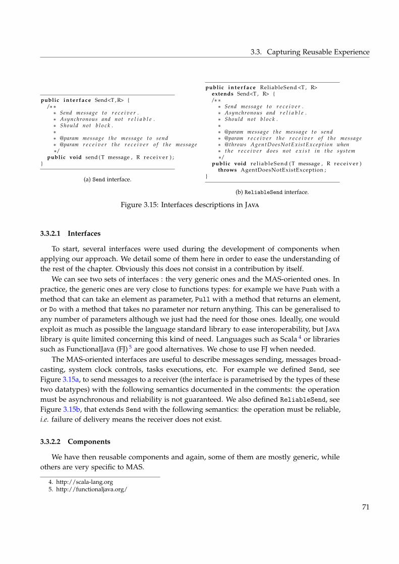
3.3. Capturing Reusable Experience
public i n t e r f a c e Send<T , R> {/∗∗
∗ Send message t o r e c e i v e r .∗ Asynchronous and not r e l i a b l e .∗ Should not b l o c k .∗∗ @param message t h e message t o send∗ @param r e c e i v e r t h e r e c e i v e r o f t h e message∗ /
public void send ( T message , R r e c e i v e r ) ;}
(a) Send interface.
public i n t e r f a c e ReliableSend <T , R>extends Send<T , R> {/∗∗
∗ Send message t o r e c e i v e r .∗ Asynchronous and r e l i a b l e .∗ Should not b l o c k .∗∗ @param message t h e message t o send∗ @param r e c e i v e r t h e r e c e i v e r o f t h e message∗ @throws A g e n t D o e s N o t E x i s t E x c e p t i o n when∗ t h e r e c e i v e r d o e s not e x i s t in t h e sys t em∗ /
public void r e l i a b l e S e n d ( T message , R r e c e i v e r )throws AgentDoesNotExistException ;
}
(b) ReliableSend interface.
Figure 3.15: Interfaces descriptions in Java
3.3.2.1 Interfaces
To start, several interfaces were used during the development of components whenapplying our approach. We detail some of them here in order to ease the understanding ofthe rest of the chapter. Obviously this does not consist in a contribution by itself.
We can see two sets of interfaces : the very generic ones and the MAS-oriented ones. Inpractice, the generic ones are very close to functions types: for example we have Push with amethod that can take an element as parameter, Pull with a method that returns an element,or Do with a method that takes no parameter nor return anything. This can be generalised toany number of parameters although we just had the need for those ones. Ideally, one wouldexploit as much as possible the language standard library to ease interoperability, but Java
library is quite limited concerning this kind of need. Languages such as Scala 4 or librariessuch as FunctionalJava (FJ) 5 are good alternatives. We chose to use FJ when needed.
The MAS-oriented interfaces are useful to describe messages sending, messages broad-casting, system clock controls, tasks executions, etc. For example we defined Send, seeFigure 3.15a, to send messages to a receiver (the interface is parametrised by the types of thesetwo datatypes) with the following semantics documented in the comments: the operationmust be asynchronous and reliability is not guaranteed. We also defined ReliableSend, seeFigure 3.15b, that extends Send with the following semantics: the operation must be reliable,i.e. failure of delivery means the receiver does not exist.
3.3.2.2 Components
We have then reusable components and again, some of them are mostly generic, whileothers are very specific to MAS.
4. http://scala-lang.org5. http://functionaljava.org/
71
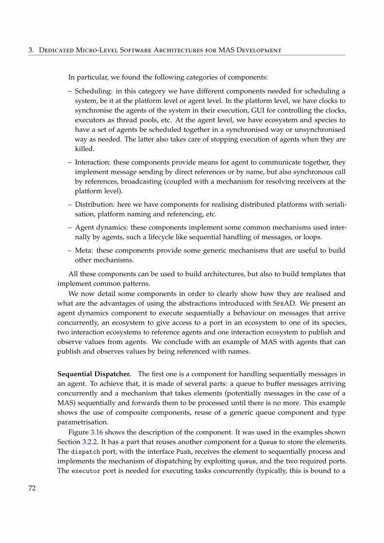
3. Dedicated Micro-Level Software Architectures for MAS Development
In particular, we found the following categories of components:
– Scheduling: in this category we have different components needed for scheduling asystem, be it at the platform level or agent level. In the platform level, we have clocks tosynchronise the agents of the system in their execution, GUI for controlling the clocks,executors as thread pools, etc. At the agent level, we have ecosystem and species tohave a set of agents be scheduled together in a synchronised way or unsynchronisedway as needed. The latter also takes care of stopping execution of agents when they arekilled.
– Interaction: these components provide means for agent to communicate together, theyimplement message sending by direct references or by name, but also synchronous callby references, broadcasting (coupled with a mechanism for resolving receivers at theplatform level).
– Distribution: here we have components for realising distributed platforms with seriali-sation, platform naming and referencing, etc.
– Agent dynamics: these components implement some common mechanisms used inter-nally by agents, such a lifecycle like sequential handling of messages, or loops.
– Meta: these components provide some generic mechanisms that are useful to buildother mechanisms.
All these components can be used to build architectures, but also to build templates thatimplement common patterns.
We now detail some components in order to clearly show how they are realised andwhat are the advantages of using the abstractions introduced with SpeAD. We present anagent dynamics component to execute sequentially a behaviour on messages that arriveconcurrently, an ecosystem to give access to a port in an ecosystem to one of its species,two interaction ecosystems to reference agents and one interaction ecosystem to publish andobserve values from agents. We conclude with an example of MAS with agents that canpublish and observes values by being referenced with names.
Sequential Dispatcher. The first one is a component for handling sequentially messages inan agent. To achieve that, it is made of several parts: a queue to buffer messages arrivingconcurrently and a mechanism that takes elements (potentially messages in the case of aMAS) sequentially and forwards them to be processed until there is no more. This exampleshows the use of composite components, reuse of a generic queue component and typeparametrisation.
Figure 3.16 shows the description of the component. It was used in the examples shownSection 3.2.2. It has a part that reuses another component for a Queue to store the elements.The dispatch port, with the interface Push, receives the element to sequentially process andimplements the mechanism of dispatching by exploiting queue, and the two required ports.The executor port is needed for executing tasks concurrently (typically, this is bound to a
72
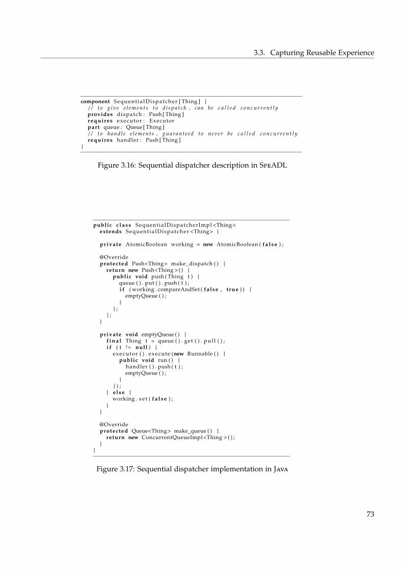
3.3. Capturing Reusable Experience
component Sequent ia lDispatcher [ Thing ] {/ / t o g i v e e l e m e n t s t o d i s p a t c h , can be c a l l e d c o n c u r r e n t l yprovides dispatch : Push [ Thing ]requires executor : Executorpart queue : Queue [ Thing ]/ / t o h a n d l e e l e m e n t s , g u a r a n t e e d t o n e v e r be c a l l e d c o n c u r r e n t l yrequires handler : Push [ Thing ]
}
Figure 3.16: Sequential dispatcher description in SpeADL
public c l a s s Sequent ia lDispatcherImpl <Thing>extends Sequent ia lDispatcher <Thing> {
private AtomicBoolean working = new AtomicBoolean ( f a l s e ) ;
@Overrideprotected Push<Thing> make_dispatch ( ) {
return new Push<Thing > ( ) {public void push ( Thing t ) {
queue ( ) . put ( ) . push ( t ) ;i f ( working . compareAndSet ( fa lse , t rue ) ) {
emptyQueue ( ) ;}
} ;} ;
}
private void emptyQueue ( ) {f i n a l Thing t = queue ( ) . get ( ) . pu l l ( ) ;i f ( t != null ) {
executor ( ) . execute (new Runnable ( ) {public void run ( ) {
handler ( ) . push ( t ) ;emptyQueue ( ) ;
}} ) ;
} e lse {working . s e t ( f a l s e ) ;
}}
@Overrideprotected Queue<Thing> make_queue ( ) {
return new ConcurrentQueueImpl<Thing > ( ) ;}
}
Figure 3.17: Sequential dispatcher implementation in Java
73
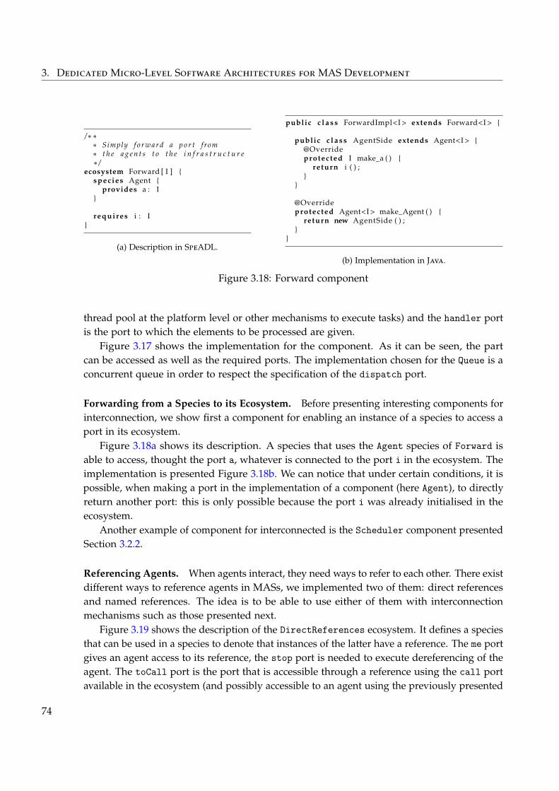
3. Dedicated Micro-Level Software Architectures for MAS Development
/∗∗∗ Simply f o r w a r d a p o r t from∗ t h e a g e n t s t o t h e i n f r a s t r u c t u r e∗ /
ecosystem Forward [ I ] {species Agent {
provides a : I}
requires i : I}
(a) Description in SpeADL.
public c l a s s ForwardImpl<I > extends Forward<I > {
public c l a s s AgentSide extends Agent<I > {@Overrideprotected I make_a ( ) {
return i ( ) ;}
}
@Overrideprotected Agent<I > make_Agent ( ) {
return new AgentSide ( ) ;}
}
(b) Implementation in Java.
Figure 3.18: Forward component
thread pool at the platform level or other mechanisms to execute tasks) and the handler portis the port to which the elements to be processed are given.
Figure 3.17 shows the implementation for the component. As it can be seen, the partcan be accessed as well as the required ports. The implementation chosen for the Queue is aconcurrent queue in order to respect the specification of the dispatch port.
Forwarding from a Species to its Ecosystem. Before presenting interesting components forinterconnection, we show first a component for enabling an instance of a species to access aport in its ecosystem.
Figure 3.18a shows its description. A species that uses the Agent species of Forward isable to access, thought the port a, whatever is connected to the port i in the ecosystem. Theimplementation is presented Figure 3.18b. We can notice that under certain conditions, it ispossible, when making a port in the implementation of a component (here Agent), to directlyreturn another port: this is only possible because the port i was already initialised in theecosystem.
Another example of component for interconnected is the Scheduler component presentedSection 3.2.2.
Referencing Agents. When agents interact, they need ways to refer to each other. There existdifferent ways to reference agents in MASs, we implemented two of them: direct referencesand named references. The idea is to be able to use either of them with interconnectionmechanisms such as those presented next.
Figure 3.19 shows the description of the DirectReferences ecosystem. It defines a speciesthat can be used in a species to denote that instances of the latter have a reference. The me portgives an agent access to its reference, the stop port is needed to execute dereferencing of theagent. The toCall port is the port that is accessible through a reference using the call portavailable in the ecosystem (and possibly accessible to an agent using the previously presented
74
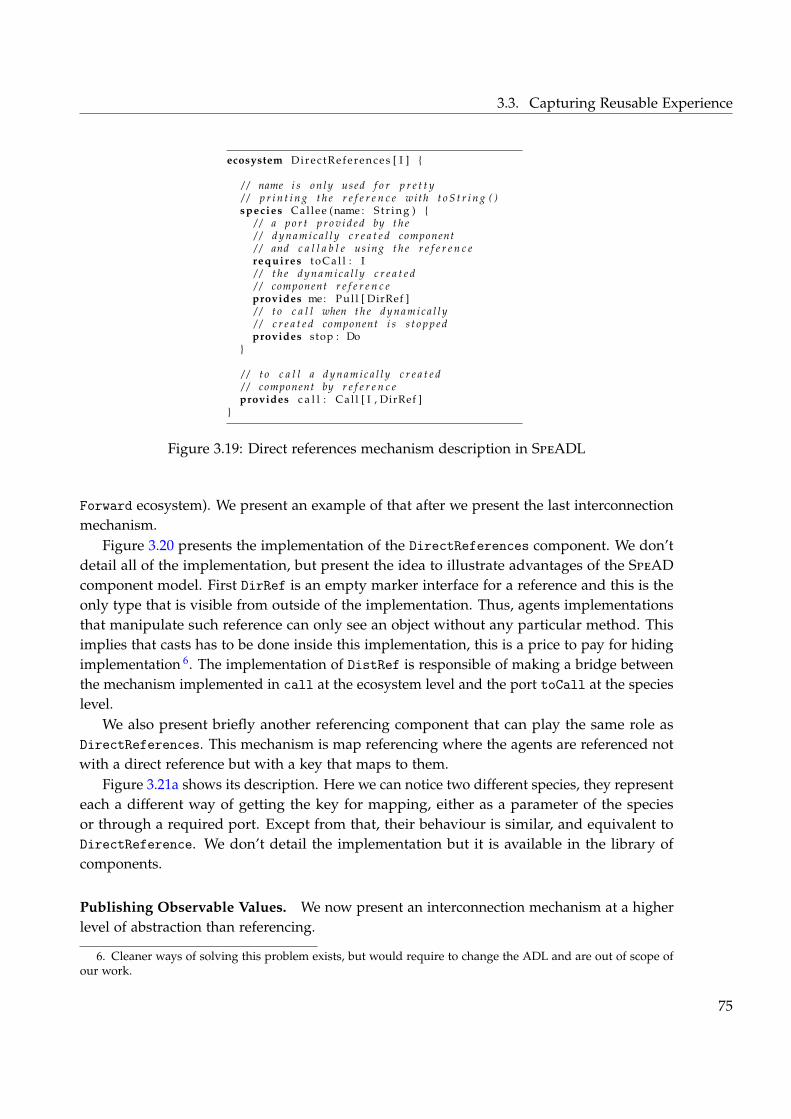
3.3. Capturing Reusable Experience
ecosystem Di rec t Refer ence s [ I ] {
/ / name i s on ly used f o r p r e t t y/ / p r i n t i n g t h e r e f e r e n c e wi th t o S t r i n g ( )species Cal lee (name : S t r i n g ) {
/ / a p o r t p r o v i d e d by t h e/ / d y n a m i c a l l y c r e a t e d component/ / and c a l l a b l e us ing t h e r e f e r e n c erequires t o C a l l : I/ / t h e d y n a m i c a l l y c r e a t e d/ / component r e f e r e n c eprovides me: Pul l [ DirRef ]/ / t o c a l l when t h e d y n a m i c a l l y/ / c r e a t e d component i s s t o p p e dprovides stop : Do
}
/ / t o c a l l a d y n a m i c a l l y c r e a t e d/ / component by r e f e r e n c eprovides c a l l : Ca l l [ I , DirRef ]
}
Figure 3.19: Direct references mechanism description in SpeADL
Forward ecosystem). We present an example of that after we present the last interconnectionmechanism.
Figure 3.20 presents the implementation of the DirectReferences component. We don’tdetail all of the implementation, but present the idea to illustrate advantages of the SpeADcomponent model. First DirRef is an empty marker interface for a reference and this is theonly type that is visible from outside of the implementation. Thus, agents implementationsthat manipulate such reference can only see an object without any particular method. Thisimplies that casts has to be done inside this implementation, this is a price to pay for hidingimplementation 6. The implementation of DistRef is responsible of making a bridge betweenthe mechanism implemented in call at the ecosystem level and the port toCall at the specieslevel.
We also present briefly another referencing component that can play the same role asDirectReferences. This mechanism is map referencing where the agents are referenced notwith a direct reference but with a key that maps to them.
Figure 3.21a shows its description. Here we can notice two different species, they representeach a different way of getting the key for mapping, either as a parameter of the speciesor through a required port. Except from that, their behaviour is similar, and equivalent toDirectReference. We don’t detail the implementation but it is available in the library ofcomponents.
Publishing Observable Values. We now present an interconnection mechanism at a higherlevel of abstraction than referencing.
6. Cleaner ways of solving this problem exists, but would require to change the ADL and are out of scope ofour work.
75
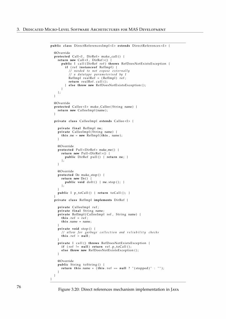
3. Dedicated Micro-Level Software Architectures for MAS Development
public c l a s s DirectReferencesImpl <I > extends Direc tReferences <I > {
@Overrideprotected Call <I , DirRef > make_call ( ) {
return new Call <I , DirRef > ( ) {public I c a l l ( DirRef r e f ) throws RefDoesNotExistsException {
i f ( r e f instanceof RefImpl ) {/ / n e ed ed t o not e x p o s e e x t e r n a l l y/ / a d a t a t y p e p a r a m e t e r i s e d by IRefImpl r e a l R e f = ( RefImpl ) r e f ;return r e a l R e f . c a l l ( ) ;
} e lse throw new RefDoesNotExistsException ( ) ;}
} ;}
@Overrideprotected Callee <I > make_Callee ( S t r i n g name) {
return new CalleeImpl (name ) ;}
private c l a s s CalleeImpl extends Callee <I > {
private f i n a l RefImpl me;private CalleeImpl ( S t r i n g name) {
t h i s .me = new RefImpl ( this , name ) ;}
@Overrideprotected Pull <DirRef > make_me ( ) {
return new Pull <DirRef > ( ) {public DirRef pul l ( ) { return me; }
} ;}
@Overrideprotected Do make_stop ( ) {
return new Do ( ) {public void doIt ( ) { me . stop ( ) ; }
} ;}public I p_toCal l ( ) { return t o C a l l ( ) ; }
}private c l a s s RefImpl implements DirRef {
private CalleeImpl r e f ;private f i n a l S t r i n g name ;private RefImpl ( CalleeImpl re f , S t r i n g name) {
t h i s . r e f = r e f ;t h i s . name = name ;
}private void stop ( ) {
/ / a l l o w f o r g a r b a g e c o l l e c t i o n and r e l i a b i l i t y c h e c k st h i s . r e f = null ;
}private I c a l l ( ) throws RefDoesNotExistsException {
i f ( r e f != null ) return r e f . p_toCal l ( ) ;e lse throw new RefDoesNotExistsException ( ) ;
}
@Overridepublic S t r i n g t o S t r i n g ( ) {
return t h i s . name + ( t h i s . r e f == null ? " ( stopped ) " : " " ) ;}
}}
Figure 3.20: Direct references mechanism implementation in Java
76
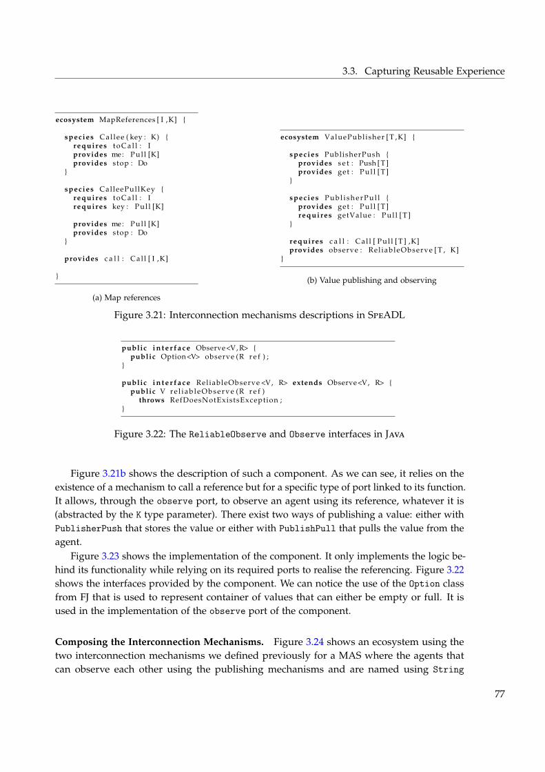
3.3. Capturing Reusable Experience
ecosystem MapReferences [ I ,K] {
species Cal lee ( key : K) {requires t o C a l l : Iprovides me: Pul l [K]provides stop : Do
}
species CalleePullKey {requires t o C a l l : Irequires key : Pul l [K]
provides me: Pul l [K]provides stop : Do
}
provides c a l l : Ca l l [ I ,K]
}
(a) Map references
ecosystem ValuePublisher [ T ,K] {
species PublisherPush {provides s e t : Push [ T ]provides get : Pul l [ T ]
}
species P u b l i s h e r P u l l {provides get : Pul l [ T ]requires getValue : Pul l [ T ]
}
requires c a l l : Ca l l [ Pul l [ T ] ,K]provides observe : Rel iableObserve [ T , K]
}
(b) Value publishing and observing
Figure 3.21: Interconnection mechanisms descriptions in SpeADL
public i n t e r f a c e Observe<V, R> {public Option<V> observe (R r e f ) ;
}
public i n t e r f a c e ReliableObserve <V, R> extends Observe<V, R> {public V r e l i a b l e O b s e r v e (R r e f )
throws RefDoesNotExistsException ;}
Figure 3.22: The ReliableObserve and Observe interfaces in Java
Figure 3.21b shows the description of such a component. As we can see, it relies on theexistence of a mechanism to call a reference but for a specific type of port linked to its function.It allows, through the observe port, to observe an agent using its reference, whatever it is(abstracted by the K type parameter). There exist two ways of publishing a value: either withPublisherPush that stores the value or either with PublishPull that pulls the value from theagent.
Figure 3.23 shows the implementation of the component. It only implements the logic be-hind its functionality while relying on its required ports to realise the referencing. Figure 3.22shows the interfaces provided by the component. We can notice the use of the Option classfrom FJ that is used to represent container of values that can either be empty or full. It isused in the implementation of the observe port of the component.
Composing the Interconnection Mechanisms. Figure 3.24 shows an ecosystem using thetwo interconnection mechanisms we defined previously for a MAS where the agents thatcan observe each other using the publishing mechanisms and are named using String
77
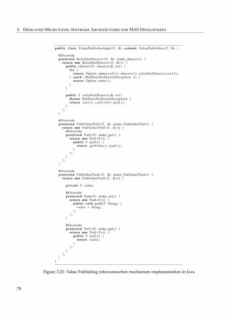
3. Dedicated Micro-Level Software Architectures for MAS Development
public c l a s s ValuePublisherImpl <T , K> extends ValuePublisher <T , K> {
@Overrideprotected ReliableObserve <T , K> make_observe ( ) {
return new ReliableObserve <T , K> ( ) {public Option<T> observe (K r e f ) {
t r y {return Option . some ( s e l f ( ) . observe ( ) . r e l i a b l e O b s e r v e ( r e f ) ) ;
} catch ( RefDoesNotExistsException e ) {return Option . none ( ) ;
}}
public T r e l i a b l e O b s e r v e (K r e f )throws RefDoesNotExistsException {return c a l l ( ) . c a l l ( r e f ) . pu l l ( ) ;
}} ;
}
@Overrideprotected Publ i sherPul l <T , K> make_PublisherPull ( ) {
return new Publ i sherPul l <T , K> ( ) {@Overrideprotected Pull <T> make_get ( ) {
return new Pull <T> ( ) {public T pul l ( ) {
return getValue ( ) . pul l ( ) ;}
} ;}
} ;}
@Overrideprotected PublisherPush <T , K> make_PublisherPush ( ) {
return new PublisherPush <T , K> ( ) {
private T value ;
@Overrideprotected Push<T> make_set ( ) {
return new Push<T> ( ) {public void push ( T thing ) {
value = thing ;} ;
} ;}
@Overrideprotected Pull <T> make_get ( ) {
return new Pull <T> ( ) {public T pul l ( ) {
return value ;}
} ;}
} ;}
}
Figure 3.23: Value Publishing interconnection mechanism implementation in Java
78
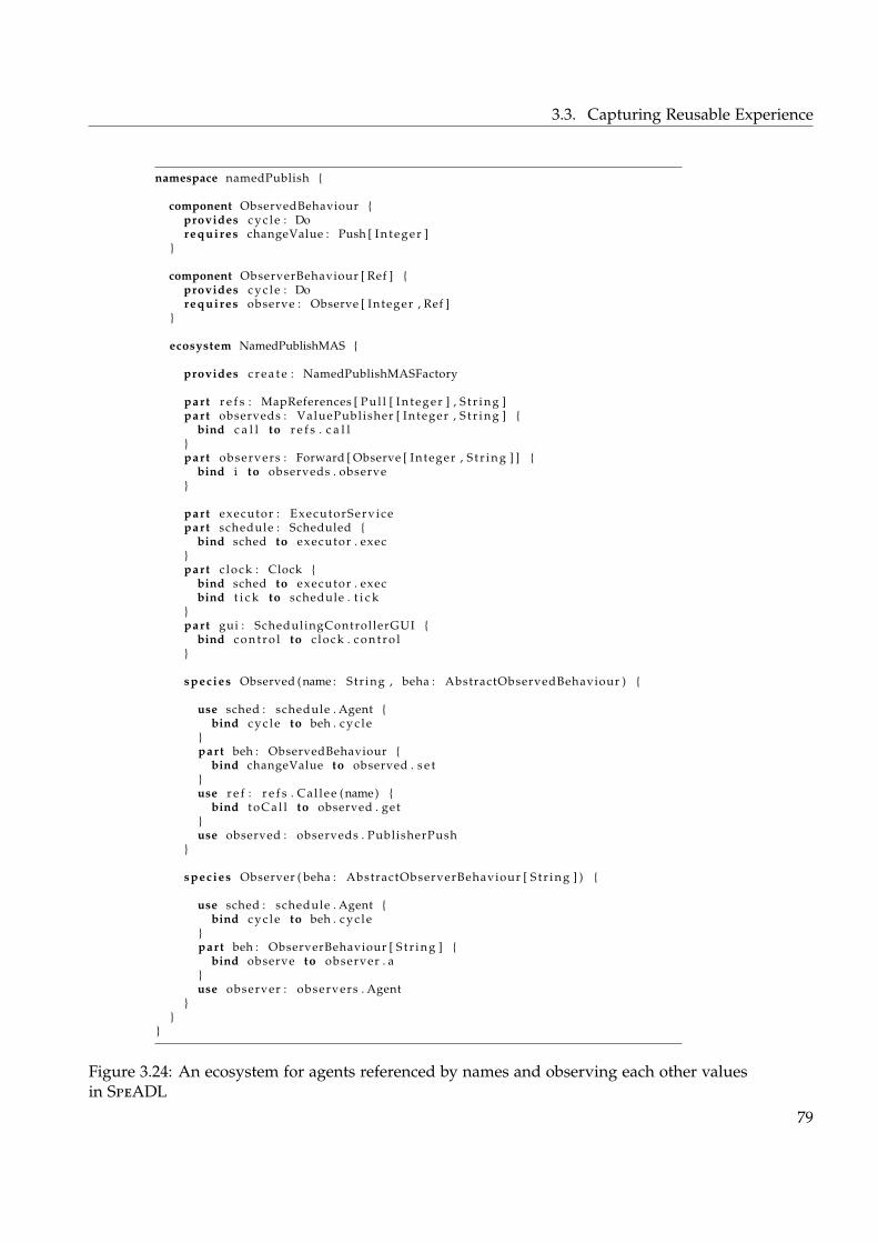
3.3. Capturing Reusable Experience
namespace namedPublish {
component ObservedBehaviour {provides c y c l e : Dorequires changeValue : Push [ I n t e g e r ]
}
component ObserverBehaviour [ Ref ] {provides c y c l e : Dorequires observe : Observe [ Integer , Ref ]
}
ecosystem NamedPublishMAS {
provides c r e a t e : NamedPublishMASFactory
part r e f s : MapReferences [ Pul l [ I n t e g e r ] , S t r i n g ]part observeds : ValuePublisher [ Integer , S t r i n g ] {
bind c a l l to r e f s . c a l l}part observers : Forward [ Observe [ Integer , S t r i n g ] ] {
bind i to observeds . observe}
part executor : ExecutorServ icepart schedule : Scheduled {
bind sched to executor . exec}part c lock : Clock {
bind sched to executor . execbind t i c k to schedule . t i c k
}part gui : SchedulingControllerGUI {
bind c o n t r o l to c lock . c o n t r o l}
species Observed (name : Str ing , beha : AbstractObservedBehaviour ) {
use sched : schedule . Agent {bind c y c l e to beh . c y c l e
}part beh : ObservedBehaviour {
bind changeValue to observed . s e t}use r e f : r e f s . Ca l lee (name) {
bind t o C a l l to observed . get}use observed : observeds . PublisherPush
}
species Observer ( beha : AbstractObserverBehaviour [ S t r i n g ] ) {
use sched : schedule . Agent {bind c y c l e to beh . c y c l e
}part beh : ObserverBehaviour [ S t r i n g ] {
bind observe to observer . a}use observer : observers . Agent
}}
}
Figure 3.24: An ecosystem for agents referenced by names and observing each other valuesin SpeADL
79
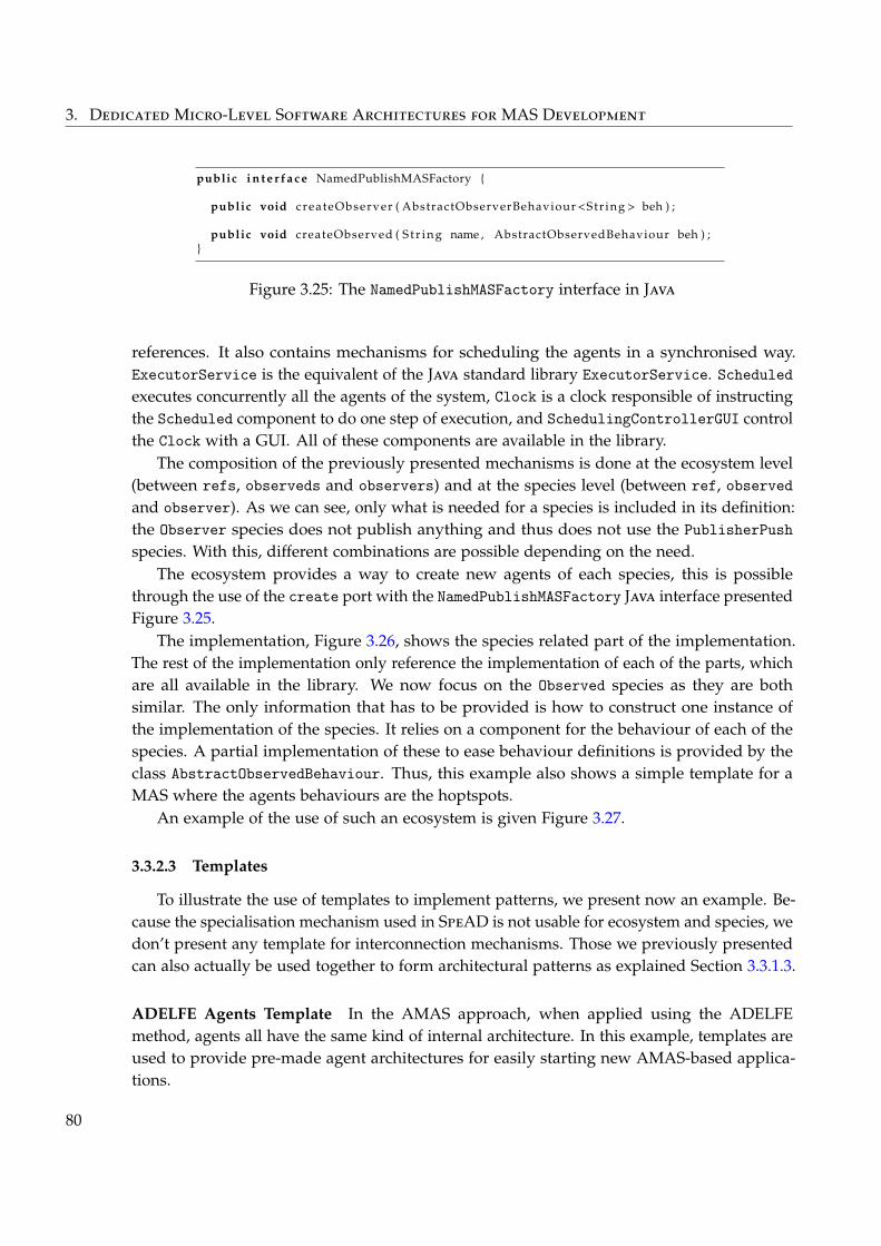
3. Dedicated Micro-Level Software Architectures for MAS Development
public i n t e r f a c e NamedPublishMASFactory {
public void createObserver ( AbstractObserverBehaviour <Str ing > beh ) ;
public void createObserved ( S t r i n g name , AbstractObservedBehaviour beh ) ;}
Figure 3.25: The NamedPublishMASFactory interface in Java
references. It also contains mechanisms for scheduling the agents in a synchronised way.ExecutorService is the equivalent of the Java standard library ExecutorService. Scheduledexecutes concurrently all the agents of the system, Clock is a clock responsible of instructingthe Scheduled component to do one step of execution, and SchedulingControllerGUI controlthe Clock with a GUI. All of these components are available in the library.
The composition of the previously presented mechanisms is done at the ecosystem level(between refs, observeds and observers) and at the species level (between ref, observedand observer). As we can see, only what is needed for a species is included in its definition:the Observer species does not publish anything and thus does not use the PublisherPushspecies. With this, different combinations are possible depending on the need.
The ecosystem provides a way to create new agents of each species, this is possiblethrough the use of the create port with the NamedPublishMASFactory Java interface presentedFigure 3.25.
The implementation, Figure 3.26, shows the species related part of the implementation.The rest of the implementation only reference the implementation of each of the parts, whichare all available in the library. We now focus on the Observed species as they are bothsimilar. The only information that has to be provided is how to construct one instance ofthe implementation of the species. It relies on a component for the behaviour of each of thespecies. A partial implementation of these to ease behaviour definitions is provided by theclass AbstractObservedBehaviour. Thus, this example also shows a simple template for aMAS where the agents behaviours are the hoptspots.
An example of the use of such an ecosystem is given Figure 3.27.
3.3.2.3 Templates
To illustrate the use of templates to implement patterns, we present now an example. Be-cause the specialisation mechanism used in SpeAD is not usable for ecosystem and species, wedon’t present any template for interconnection mechanisms. Those we previously presentedcan also actually be used together to form architectural patterns as explained Section 3.3.1.3.
ADELFE Agents Template In the AMAS approach, when applied using the ADELFEmethod, agents all have the same kind of internal architecture. In this example, templates areused to provide pre-made agent architectures for easily starting new AMAS-based applica-tions.
80
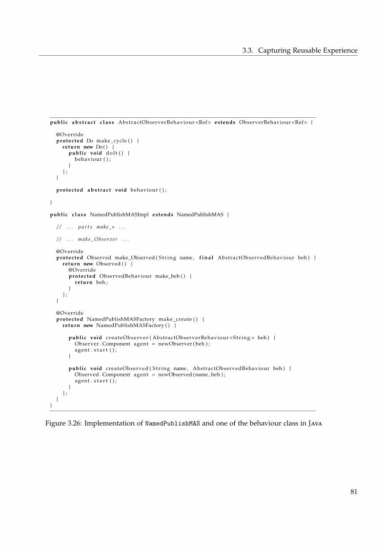
3.3. Capturing Reusable Experience
public a b s t r a c t c l a s s AbstractObserverBehaviour <Ref> extends ObserverBehaviour <Ref> {
@Overrideprotected Do make_cycle ( ) {
return new Do ( ) {public void doIt ( ) {
behaviour ( ) ;}
} ;}
protected a b s t r a c t void behaviour ( ) ;
}
public c l a s s NamedPublishMASImpl extends NamedPublishMAS {
/ / . . . p a r t s make_∗ . . .
/ / . . . make_Observer . . .
@Overrideprotected Observed make_Observed ( S t r i n g name , f i n a l AbstractObservedBehaviour beh ) {
return new Observed ( ) {@Overrideprotected ObservedBehaviour make_beh ( ) {
return beh ;}
} ;}
@Overrideprotected NamedPublishMASFactory make_create ( ) {
return new NamedPublishMASFactory ( ) {
public void createObserver ( AbstractObserverBehaviour <Str ing > beh ) {Observer . Component agent = newObserver ( beh ) ;agent . s t a r t ( ) ;
}
public void createObserved ( S t r i n g name , AbstractObservedBehaviour beh ) {Observed . Component agent = newObserved ( name , beh ) ;agent . s t a r t ( ) ;
}} ;
}}
Figure 3.26: Implementation of NamedPublishMAS and one of the behaviour class in Java
81
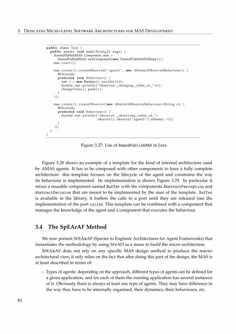
3. Dedicated Micro-Level Software Architectures for MAS Development
public c l a s s Test {public s t a t i c void main ( S t r i n g [ ] args ) {
NamedPublishMAS . Component mas =NamedPublishMAS . newComponent (new NamedPublishMASImpl ( ) ) ;
mas . s t a r t ( ) ;
mas . c r e a t e ( ) . createObserved ( " agent1 " , new AbstractObservedBehaviour ( ) {@Overrideprotected void behaviour ( ) {
i n t v = new Random ( ) . n e x t I n t ( 1 0 ) ;System . out . p r i n t l n ( " observed : changing value to "+v ) ;changeValue ( ) . push ( v ) ;
}} ) ;
mas . c r e a t e ( ) . createObserver (new AbstractObserverBehaviour <Str ing > ( ) {@Overrideprotected void behaviour ( ) {
System . out . p r i n t l n ( " observer : observing value of "+observe ( ) . observe ( " agent1 " ) . orSome ( −1 ) ) ;
}} ) ;
}}
Figure 3.27: Use of NamedPublishMAS in Java
Figure 3.28 shows an example of a template for the kind of internal architecture usedby AMAS agents. It has to be composed with other components to have a fully completearchitecture: this template focuses on the lifecycle of the agent and constrains the wayits behaviour is implemented. Its implementation is shown Figure 3.29. In particular itmixes a reusable component named Buffer with the components AbstractPerception andAbstractDecision that are meant to be implemented by the user of the template. Bufferis available in the library, it buffers the calls to a port until they are released (see theimplementation of the port cycle). This template can be combined with a component thatmanages the knowledge of the agent and a component that executes the behaviour.
3.4 The SpEArAF Method
We now present SpEArAF (Species to Engineer Architectures for Agent Frameworks) thatinstantiates the methodology by using SpeAD as a mean to build the micro-architecture.
SpEArAF does not rely on any specific MAS design method to produce the macro-architectural view, it only relies on the fact that after doing this part of the design, the MAS isat least described in terms of:
– Types of agents: depending on the approach, different types of agents can be defined fora given application, and for each of them the running application has several instancesof it. Obviously there is always at least one type of agents. They may have difference inthe way they have to be internally organised, their dynamics, their behaviours, etc.
82
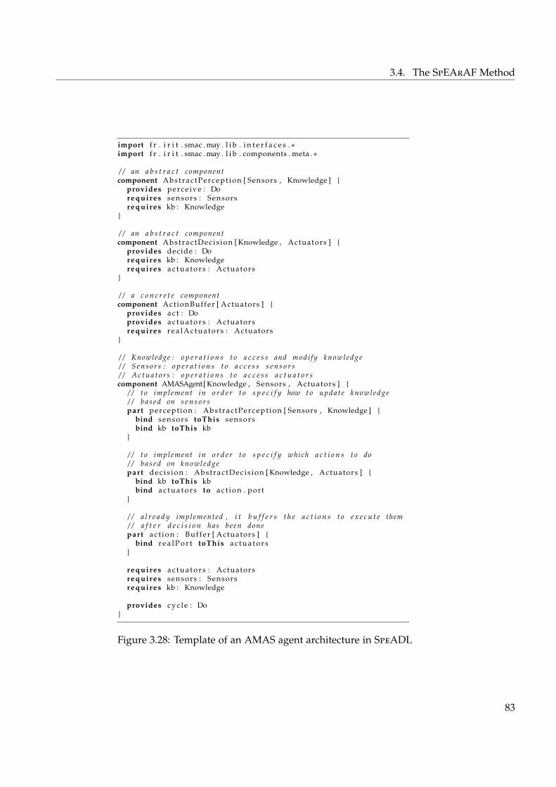
3.4. The SpEArAF Method
import f r . i r i t . smac . may . l i b . i n t e r f a c e s .∗import f r . i r i t . smac . may . l i b . components . meta .∗
/ / an a b s t r a c t componentcomponent Abstrac tPercept ion [ Sensors , Knowledge ] {
provides perce ive : Dorequires sensors : Sensorsrequires kb : Knowledge
}
/ / an a b s t r a c t componentcomponent Abstrac tDec is ion [ Knowledge , Actuators ] {
provides decide : Dorequires kb : Knowledgerequires a c t u a t o r s : Actuators
}
/ / a c o n c r e t e componentcomponent ActionBuffer [ Actuators ] {
provides a c t : Doprovides a c t u a t o r s : Actuatorsrequires r e a l A c t u a t o r s : Actuators
}
/ / Knowledge : o p e r a t i o n s t o a c c e s s and modi fy knowledge/ / S e n s o r s : o p e r a t i o n s t o a c c e s s s e n s o r s/ / A c t u a t o r s : o p e r a t i o n s t o a c c e s s a c t u a t o r scomponent AMASAgent[ Knowledge , Sensors , Actuators ] {
/ / t o implement in o r d e r t o s p e c i f y how t o up da t e knowledge/ / b a s e d on s e n s o r spart percept ion : Abst rac tPercept ion [ Sensors , Knowledge ] {
bind sensors toThis sensorsbind kb toThis kb
}
/ / t o implement in o r d e r t o s p e c i f y which a c t i o n s t o do/ / b a s e d on knowledgepart d e c i s i o n : Abstrac tDec is ion [ Knowledge , Actuators ] {
bind kb toThis kbbind a c t u a t o r s to a c t i o n . port
}
/ / a l r e a d y implemented , i t b u f f e r s t h e a c t i o n s t o e x e c u t e them/ / a f t e r d e c i s i o n has been donepart a c t i o n : Buf fer [ Actuators ] {
bind r e a l P o r t toThis a c t u a t o r s}
requires a c t u a t o r s : Actuatorsrequires sensors : Sensorsrequires kb : Knowledge
provides c y c l e : Do}
Figure 3.28: Template of an AMAS agent architecture in SpeADL
83
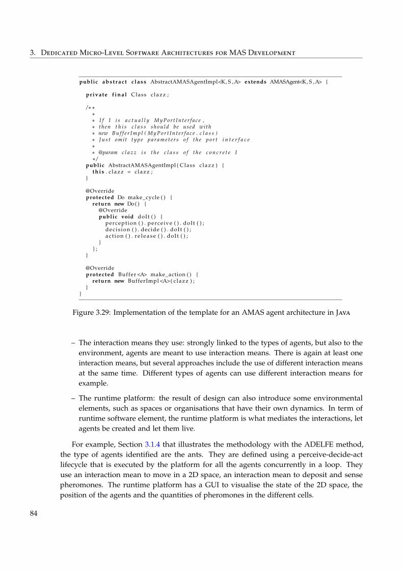
3. Dedicated Micro-Level Software Architectures for MAS Development
public a b s t r a c t c l a s s AbstractAMASAgentImpl<K, S ,A> extends AMASAgent<K, S ,A> {
private f i n a l Class c l a z z ;
/∗∗∗∗ I f I i s a c t u a l l y M y P o r t I n t e r f a c e ,∗ th en t h i s c l a s s s h o u l d be used with∗ new B u f f e r I m p l ( M y P o r t I n t e r f a c e . c l a s s )∗ J u s t omit t y p e p a r a m e t e r s o f t h e p o r t i n t e r f a c e∗∗ @param c l a z z i s t h e c l a s s o f t h e c o n c r e t e I∗ /
public AbstractAMASAgentImpl ( Class c l a z z ) {t h i s . c l a z z = c l a z z ;
}
@Overrideprotected Do make_cycle ( ) {
return new Do ( ) {@Overridepublic void doIt ( ) {
percept ion ( ) . perce ive ( ) . doI t ( ) ;d e c i s i on ( ) . decide ( ) . doI t ( ) ;a c t i o n ( ) . r e l e a s e ( ) . doI t ( ) ;
}} ;
}
@Overrideprotected Buffer <A> make_action ( ) {
return new BufferImpl <A>( c l a z z ) ;}
}
Figure 3.29: Implementation of the template for an AMAS agent architecture in Java
– The interaction means they use: strongly linked to the types of agents, but also to theenvironment, agents are meant to use interaction means. There is again at least oneinteraction means, but several approaches include the use of different interaction meansat the same time. Different types of agents can use different interaction means forexample.
– The runtime platform: the result of design can also introduce some environmentalelements, such as spaces or organisations that have their own dynamics. In term ofruntime software element, the runtime platform is what mediates the interactions, letagents be created and let them live.
For example, Section 3.1.4 that illustrates the methodology with the ADELFE method,the type of agents identified are the ants. They are defined using a perceive-decide-actlifecycle that is executed by the platform for all the agents concurrently in a loop. Theyuse an interaction mean to move in a 2D space, an interaction mean to deposit and sensepheromones. The runtime platform has a GUI to visualise the state of the 2D space, theposition of the agents and the quantities of pheromones in the different cells.
84
3.4. The SpEArAF Method
In the following we map the concepts of types of agents, interaction means and run-time platform to those available in SpeAD in order to realise a partially abstract micro-architecture. We then present an iterative and incremental design process for building thismicro-architecture. We conclude with guidelines that are useful when applying the methodin practice.
3.4.1 Component-Based Architectures for MASs
The platform is implemented using an ecosystem: its sub-components represent differentmechanisms at the environment level, such as 2D plan, extra-agent organisation dynamics,but also scheduling, distribution, visualisation GUI, etc.
Types of agents are implemented using species and are created and maintained “alive” bythe ecosystem: components in the species represent internal mechanisms and dynamics suchas lifecycles, adaptation, GUI, capabilities, knowledge management etc.
Interconnection mechanisms are implemented using a combination of ecosystem andspecies, used inside the environment ecosystem and composed into the different types ofagents species. They can be sensors, actuators, messages passing and other interactionmeans, but also scheduler, visualisation and other operative links between the agents and theplatform.
As we said, we propose to describe the micro-architecture as an architecture with holes,that we also call partially abstract architecture: some components of the architecture areprovided implemented, while others are left abstracts for implementation by the MASdeveloper. The way to describe such architecture using templates is presented Section 3.3.The basic idea behind this point is to find what are the concrete and the abstract componentsof the architecture. The programming abstractions, as presented Section 3.1, that the MASdeveloper can use to focus on his business concerns are then provided by the architecture inthe form of abstract components. Concrete components would be the rest of the architecture,not meant to be modified by the MAS developer.
3.4.2 Iterative and Incremental Micro-Architectural Design
The following gives a process to build the partially abstract micro-architecture that canthen be used as a development support.
This process is driven by the requirements. When the process starts, the requirements arethose we identified in the methodology Section 3.1, but the more the micro-architecture getrefined, the more detailed requirements are elicited and are what need to be implemented atone point or another. This process is mainly inspired by the ADD (Attribute-Driven Design) For a pre-
sentation ofADD, see p. 8
For a pre-sentation ofADD, see p. 8method for the iterative refinement of the architecture and the “Twin Peaks” model for the
For a presen-tation of theTwin PeaksModel, seep. 7
For a presen-tation of theTwin PeaksModel, seep. 7
incremental definition of both requirements and architecture.The iterated cycles of the process are separated in two phases: species and ecosystem.
Every step helps identifying new elements to define the architectures. They must be repeateduntil no more requirement is present. Each phase of a cycle starts with a set of requirements
85
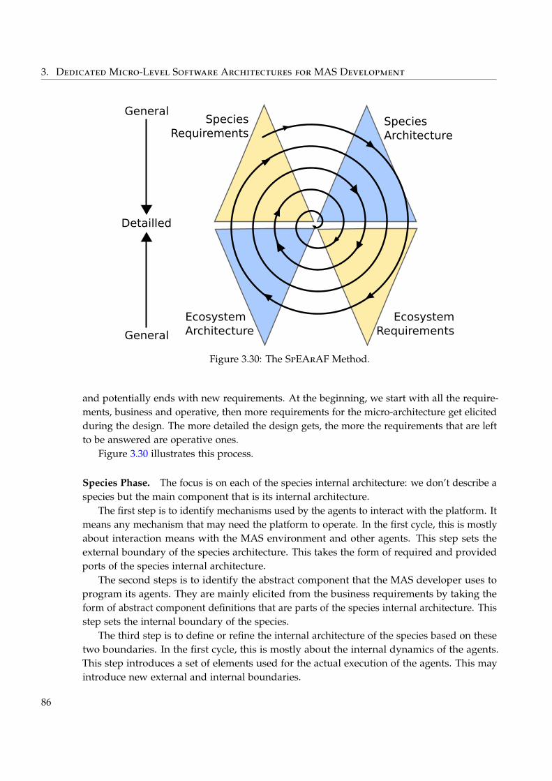
3. Dedicated Micro-Level Software Architectures for MAS Development
SpeciesArchitecture
SpeciesRequirements
EcosystemRequirements
EcosystemArchitecture
Detailled
General
General
Figure 3.30: The SpEArAF Method.
and potentially ends with new requirements. At the beginning, we start with all the require-ments, business and operative, then more requirements for the micro-architecture get elicitedduring the design. The more detailed the design gets, the more the requirements that are leftto be answered are operative ones.
Figure 3.30 illustrates this process.
Species Phase. The focus is on each of the species internal architecture: we don’t describe aspecies but the main component that is its internal architecture.
The first step is to identify mechanisms used by the agents to interact with the platform. Itmeans any mechanism that may need the platform to operate. In the first cycle, this is mostlyabout interaction means with the MAS environment and other agents. This step sets theexternal boundary of the species architecture. This takes the form of required and providedports of the species internal architecture.
The second steps is to identify the abstract component that the MAS developer uses toprogram its agents. They are mainly elicited from the business requirements by taking theform of abstract component definitions that are parts of the species internal architecture. Thisstep sets the internal boundary of the species.
The third step is to define or refine the internal architecture of the species based on thesetwo boundaries. In the first cycle, this is mostly about the internal dynamics of the agents.This step introduces a set of elements used for the actual execution of the agents. This mayintroduce new external and internal boundaries.
86
3.4. The SpEArAF Method
All the external boundaries are requirements towards the ecosystem for the species toproperly operate.
Ecosystem Phase. Starting from the external boundary of each of the species, as well as theother requirements, a new version of the ecosystem architecture can be defined. For example,at the beginning, the dynamics of the platform should be devised.
For every species internal architecture, a species is defined and must be refined to linkit to the ecosystem. New elements are introduced in the ecosystem and in the species. Inorder to realise the links between the ecosystem and the species, some of these elements arethemselves ecosystems whose species are used in the agents’ species and connected to itsinternal architecture ports. Most of the time, these elements are reused, but when needed,new one may have to be defined. These mechanisms, because they are meant to be part ofother species, may have required and provided ports to be usable. In complex cases, thecurrent process can be applied recursively to them.
In the same way than the species internal architectures, it is advised to start with businessrequirements and materialise them using abstract components at the ecosystem level.
All of this can add new requirements towards the species internal architectures.After this phase, a cycle ends and it may be needed to go back to start a new cycle and so
on until all the requirements are answered.
3.4.3 Additional Guidelines
We now present several guidelines that were discovered during the application of such aprocess to design the micro-architecture of MASs. These are informally detailed.
What should be a Species Based on the macro-level architectural, several types of agentsare identified with their interaction mechanisms and other explicit and implicit requirementsrelated to how agents at runtime are connected to the runtime platform. But other entitiesidentified at the macro-level design may also be modelled with species at micro-level design.The main guidelines is to see if the type of entities concerned is likely to be:
1. Created dynamically.
2. Interacting with agents (or other entities, depending on the MAS approach) usinginteraction mechanisms such as those used by agents.
Decomposition. When decomposing the architecture in different parts, the question ofwhere to put some of the components and their functionality occurs. For example, should theGUI controlling a MAS be inside the ecosystem with the species or outside the ecosystem ina composite that contains the ecosystem and other components.
As a general guideline, it seems that it is preferable to keep the ecosystem focused onMAS mechanisms, and thus any element not directly concerned with the agents and theirinteractions would gain to be composed with the ecosystem in a component representing theapplication itself.
87
3. Dedicated Micro-Level Software Architectures for MAS Development
Actually, often in MAS approaches, MASs are considered to exist inside a computationalenvironment that gives feedback to it or gets results from it. This environment is not aware ofthe fact it is interacting with a MAS but sees it as a blackbox with clearly defined interfaces.But on top of the agents and their platform, what is considered the MAS also contains partsaware of the fact they are interacting with a MAS without themselves being part of the MAS.A common way of decomposing this kind of systems is:
1. One ecosystem for the MAS itself exposing MAS-oriented ports.
2. One component containing it and representing the part of the system aware of the factit is a MAS and exposing MAS-agnostic ports.
3. One component for the actual final application that contains it.
Mapping between Views. It is a good practice, when applying the process, to keep track ofthe mapping between the elements of the micro-architectural view and the macro-architecturalview as it is often recommended in software architecture practice.
In particular, in the context of MAS development, this is particularly important to recordthe mapping between types of agents and the corresponding species.
3.5 Conclusion
We presented in this chapter a coherent set of answers to the challenges identifiedpreviously.
First, we detailed our vision of the methodology of MAS development as a direct responseto the analysis made Chapter 2. By separating the design of the MAS itself — called macro-architectural design — from the design of the architecture that support its implementation— called micro-architectural design —, this highlighted architectural and implementationchallenges for building the latter.
The SpeAD component model we present next answers such challenges while takinginto account our desire of easing the development and improving the quality and reuse ofsoftware produced during MAS development. By choosing a component-oriented approach,it is possible to build an architecture adapted to the needs of the application to be built,but also to the concerns of the MAS developer. This thus gives the possibility, when doingmacro-architectural design to focus on the business concerns of the application. At the sametime, by making explicit the micro-architectural design and all the requirements it answers,this helps to make a bridge between design and implementation.
Finally, to build such micro-architecture, the SpEArAF development method positionsthe exploitation SpeAD into the general proposed methodology and provides guidelines toincrementally and iteratively use it.
To better understand how all of this can be used in combination with existing MASdevelopment methods and how practically it is applied, next chapter presents an example ofa real MAS-based application for a research project with industrial partners. This applicationends with a quick discussion on the advantages of using our contribution, and a complete
88
3.5. Conclusion
analysis of the contribution is then presented Chapter 5. It is accompanied by a presentationof academic and industrial works using our contribution and a positioning with respect toother research works on MAS development.
Furthermore, Chapter 6 proposes a positioning of the contribution with respect to existingworks in the software architecture field.
Summary of the Contributions⊕We propose a methodology of MAS development that allows to take into account allthe specific types of requirements that exist in MAS development.⊕We propose the SpeAD (Species-based Architectural Design) component model thatenables to design and implement the micro-level architecture of a MAS.⊕We propose the SpEArAF (Species to Engineer Architectures for Agent Frameworks)method that instantiates the methodology using SpeAD.⊕We present guidelines on how to reuse knowledge and experience using SpeAD.⊕We present reusable components that are part of a component library.
89

CHAPTER 4Application
En mai, fais ce qu’il te plaît.
Proverbe français
In this chapter, to illustrate the whole lifecycle of the development of a MAS, we nowapply SpEArAF with SpeAD after following a macro-level design method on an example.This was completely applied in practice to implement this example using MAY (Make Agents
Yourself), the tool presented Appendix B that supports the SpeAD component model.This example is taken from a real world application developed in our research team for
a research project with industrial partners named GAMBITS 1. The objective of this projectis to provide training to maritime surveillance operators. These operators use a softwaresystem that assists them to supervise maritime zones and detect suspicious behaviours. Inorder to train them to the software, the project exploits a serious game approach. A seriousgame is “a mental contest, played with a computer in accordance with specific rules that usesentertainment to further government or corporate training, education, health, public policy,and strategic communication objectives” (Zyda 2005). In our case, the type of game used is atower defence game were the objective is to protect a zone from enemies by placing defencetowers on a map. For example, the enemies are the lawbreaker boats and the towers are staticradars, mobile radars or patrols.
The objective of our research team in the project is to provide an intelligent self-adaptiveMAS able to control the game in order to adapt at runtime its difficulty and behaviour to thelevel of the operators in training. The idea is that such a game provides a lot of informationson a running session, from which it is possible to infer the learning success of the player.Based on that information and on domain-specific constraints elicited by the trainers, thesystem must control continuously the parameters of the game so that the learning curve ofthe player is progressive and that some wanted educational objectives are reached.
1. Game-Based Intelligent Strategies: http://www.gambits.fr/, financed by the French DGCIS (DirectionGénérale de la Compétitivité, de l’Industrie et des Services).
91
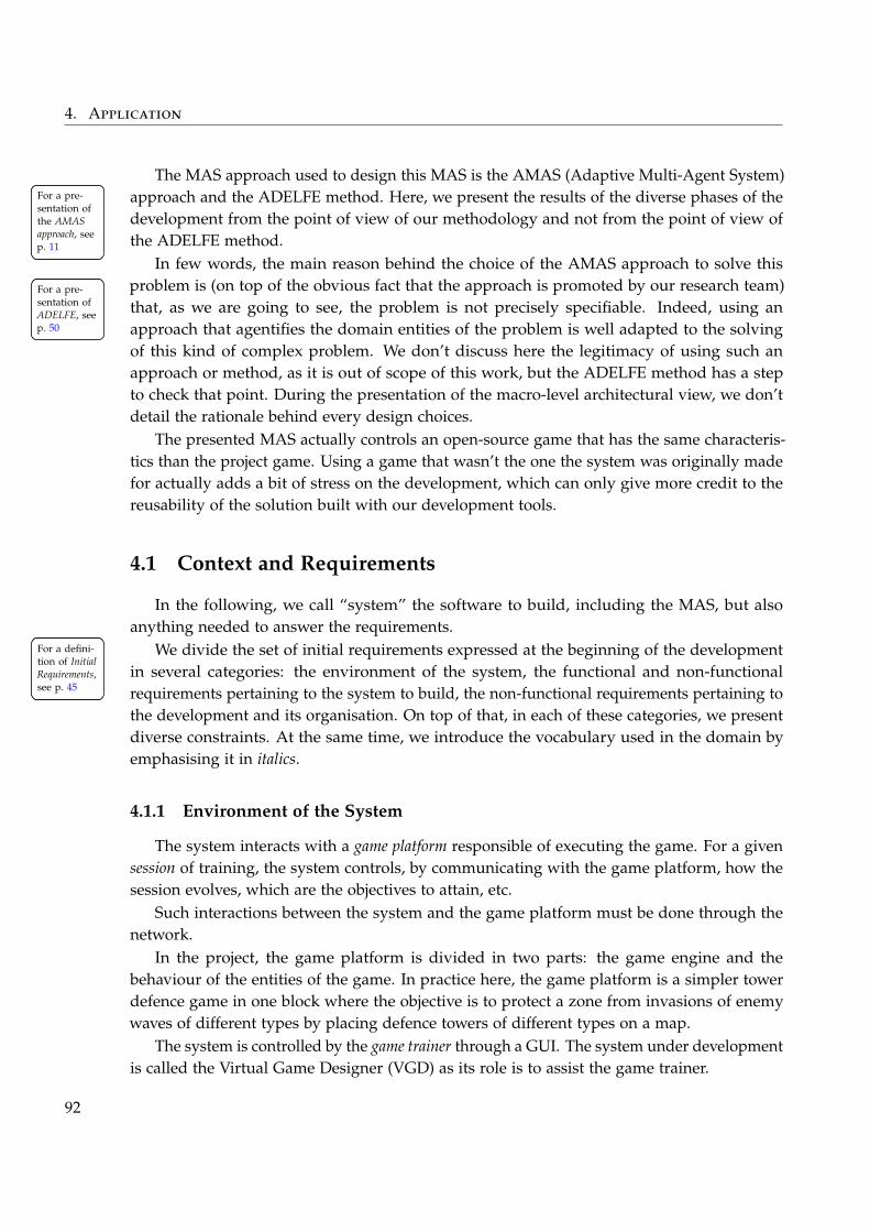
4. Application
The MAS approach used to design this MAS is the AMAS (Adaptive Multi-Agent System)approach and the ADELFE method. Here, we present the results of the diverse phases of theFor a pre-
sentation ofthe AMASapproach, seep. 11
For a pre-sentation ofthe AMASapproach, seep. 11
For a pre-sentation ofADELFE, seep. 50
For a pre-sentation ofADELFE, seep. 50
development from the point of view of our methodology and not from the point of view ofthe ADELFE method.
In few words, the main reason behind the choice of the AMAS approach to solve thisproblem is (on top of the obvious fact that the approach is promoted by our research team)that, as we are going to see, the problem is not precisely specifiable. Indeed, using anapproach that agentifies the domain entities of the problem is well adapted to the solvingof this kind of complex problem. We don’t discuss here the legitimacy of using such anapproach or method, as it is out of scope of this work, but the ADELFE method has a stepto check that point. During the presentation of the macro-level architectural view, we don’tdetail the rationale behind every design choices.
The presented MAS actually controls an open-source game that has the same characteris-tics than the project game. Using a game that wasn’t the one the system was originally madefor actually adds a bit of stress on the development, which can only give more credit to thereusability of the solution built with our development tools.
4.1 Context and Requirements
In the following, we call “system” the software to build, including the MAS, but alsoanything needed to answer the requirements.
We divide the set of initial requirements expressed at the beginning of the developmentFor a defini-tion of InitialRequirements,see p. 45
For a defini-tion of InitialRequirements,see p. 45
in several categories: the environment of the system, the functional and non-functionalrequirements pertaining to the system to build, the non-functional requirements pertaining tothe development and its organisation. On top of that, in each of these categories, we presentdiverse constraints. At the same time, we introduce the vocabulary used in the domain byemphasising it in italics.
4.1.1 Environment of the System
The system interacts with a game platform responsible of executing the game. For a givensession of training, the system controls, by communicating with the game platform, how thesession evolves, which are the objectives to attain, etc.
Such interactions between the system and the game platform must be done through thenetwork.
In the project, the game platform is divided in two parts: the game engine and thebehaviour of the entities of the game. In practice here, the game platform is a simpler towerdefence game in one block where the objective is to protect a zone from invasions of enemywaves of different types by placing defence towers of different types on a map.
The system is controlled by the game trainer through a GUI. The system under developmentis called the Virtual Game Designer (VGD) as its role is to assist the game trainer.
92
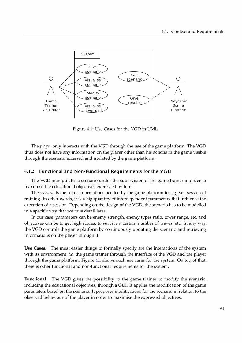
4.1. Context and Requirements
GameTrainer
via Editor
Givescenario
Visualisescenario
Modifyscenario
Getscenario
Player viaGame
Platform
Giveresults
System
Visualiseplayer perf.
Figure 4.1: Use Cases for the VGD in UML
The player only interacts with the VGD through the use of the game platform. The VGDthus does not have any information on the player other than his actions in the game visiblethrough the scenario accessed and updated by the game platform.
4.1.2 Functional and Non-Functional Requirements for the VGD
The VGD manipulates a scenario under the supervision of the game trainer in order tomaximise the educational objectives expressed by him.
The scenario is the set of informations needed by the game platform for a given session oftraining. In other words, it is a big quantity of interdependent parameters that influence theexecution of a session. Depending on the design of the VGD, the scenario has to be modelledin a specific way that we thus detail later.
In our case, parameters can be enemy strength, enemy types ratio, tower range, etc, andobjectives can be to get high scores, to survive a certain number of waves, etc. In any way,the VGD controls the game platform by continuously updating the scenario and retrievinginformations on the player through it.
Use Cases. The most easier things to formally specify are the interactions of the systemwith its environment, i.e. the game trainer through the interface of the VGD and the playerthrough the game platform. Figure 4.1 shows such use cases for the system. On top of that,there is other functional and non-functional requirements for the system.
Functional. The VGD gives the possibility to the game trainer to modify the scenario,including the educational objectives, through a GUI. It applies the modification of the gameparameters based on the scenario. It proposes modifications for the scenario in relation to theobserved behaviour of the player in order to maximise the expressed objectives.
93
4. Application
Non-Functional. The propositions of the VGD must be given in real time. The modificationof the parameters must be done in real time. The VGD must self-adapt its control to theplayer’s behaviour.
Comments. As we can see, the requirements for the system itself are difficult to specifyprecisely. Indeed, we don’t have any formal way of specifying what it means to maximisethe expressed objectives in another way than saying, for example, that the score goes up,or what it means to adapt to the player in another way than saying, for example that theparameters should be modified in order for the game to be easier and that the score goes up.Such a specification is useless if we were to decompose the system in sub-parts following areductionist approach. Here, as we are going to see, the idea here is to model the problemFor a re-
minder onreductionism,see p. 10
For a re-minder onreductionism,see p. 10
itself and let its various entities self-organise to find a good solution. This is actually one ofthe reasons the AMAS approach is used to tackle such a problem.
4.1.3 Non-Functional Requirements for the Development
Even though the presented solution is using a simpler game than in the project, thischange happened only at the end of the development in order to have a working prototype.Thus the development followed the organisation of the project that we now present with itsrequirements and constraints.
The development team is organised in three groups. One of them focuses on the VGD,with one developer, whose work we describe here. Another group is responsible for therealism of the behaviour of the game platform (exploiting the parameters of the scenario) andthe last one is taking care of the game engine itself.
The main requirement for the development is about tuning: the developer needs tovisualise the internal execution of the VGD to support its tuning during the development.Such visualisation must be removable when working with the other teams during integration.As we are going to see, this manifests itself in a particular way when using MASs.
Other requirements actually appear later in the development. Indeed, the methodology ofMAS we propose relies on the fact that after the MAS design is done, it is needed to extractnew requirements from it in order to tackle implementation. They are thus detailed whenneeded.
4.2 Macro-level Architectural Design
As we said, the approach chosen is the AMAS approach with the ADELFE method. Inthis approach, the idea is to agentify the entities of the domain problem and give them thebehaviours that will drive them to collectively find a solution.
The first need is thus to extract the micro-requirements the approach answers, and thenprecisely define the domain problem, which here is the scenario and its adaptation. Based onthat, the MAS design can be done.
94
4.2. Macro-level Architectural Design
4.2.1 Macro-Level Requirements Extraction
Some of the requirements presented Section 4.1 are directly be answered by the MASdesign: they form the set of the macro-level requirements. For a defini-
tion of Macro-Level Require-ments, seep. 47
For a defini-tion of Macro-Level Require-ments, seep. 47
These requirements are:
– The functional requirements, except for the GUI interactions with the game trainer andthe scenario transmission to the game platform.
– The non-functional requirements, in particular those about adaptivity.
All the rest is not directly tackled by the MAS design except for the fact that the stateof the agents must be easily accessible for tuning: for example it means it is not possible todistribute the agents on a lot of machines. Happily, this is not needed here, but this showsthe kind of implication some requirements can have on the design.
4.2.2 Problem Domain Model
A scenario is composed of parameters whose values exist inside a range specific to it. Thevalues of these parameters define how the session goes on. For example, some parameters forthe game platform can be the speed of the enemy entities and the defences efficiency.
On top of these low-level informations, the scenario is also composed of higher-levelinformations that influence the orientations the scenario should take during the session. Theyare used by the game trainer to define the objectives to attain and under which conditions.The difference is made between the measured criteria, which represent information comingfrom the game platform, and the criteria, which represent aggregations of the other domainentities. The concept of criterion is not directly represented in the game platform itself but isexpressible using the low-level parameters and the other, possibly measured, criteria. Forexample, a criterion for our game platform can be the ratio of a specific type of enemy entities.The measured criteria are typically used to represent things like the score, i.e. the number ofkilled entities per wave.
Then, some dependencies between parameters and between parameters and criteria areused to express how their values should evolve during the scenario. They are expressedthrough the use of a matrix that says in which direction (positive or negative) the evolution ofa parameter should influence another one. The actual strength of the influence is somethingthat can evolve at runtime and is controlled by the VGD. The dependencies are domain-specific knowledge expressed by the game trainer. An example of dependencies is that thescore is inversely dependent to the speed of the enemy entities.
All these informations are provided by the expert. The system manipulates and controlsthem to make the player reach the wanted objectives. Constraints can be expressed on eachcriterion and parameter: they can for example be desired values, ranges, etc. Objectives areconstraints on criteria that can’t be directly controlled. They must be enforced by the systemand trigger its self-adaptation.
95
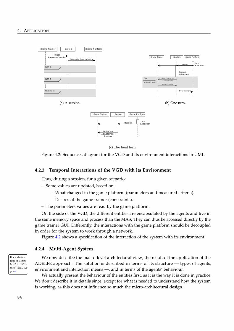
4. Application
:Game Trainer :System :Game Platform
InitialScenario Creation
turn 1
Scenario Transmission
turn n
...
f inal turn
(a) A session.
:System :Game Platform
Results
ScenarioAdjustment
:Game Trainer
New ScenarioTransmission
Modification
New Scenario
TurnExecution
Opt
[manual mode]
(b) One turn.
:System :Game Platform
Results
:Game Trainer
TurnExecution
End of theAdjustement
Process
(c) The final turn.
Figure 4.2: Sequences diagram for the VGD and its environment interactions in UML
4.2.3 Temporal Interactions of the VGD with its Environment
Thus, during a session, for a given scenario:
– Some values are updated, based on:
– What changed in the game platform (parameters and measured criteria).
– Desires of the game trainer (constraints).
– The parameters values are read by the game platform.
On the side of the VGD, the different entities are encapsulated by the agents and live inthe same memory space and process than the MAS. They can thus be accessed directly by thegame trainer GUI. Differently, the interactions with the game platform should be decoupledin order for the system to work through a network.
Figure 4.2 shows a specification of the interaction of the system with its environment.
4.2.4 Multi-Agent System
We now describe the macro-level architectural view, the result of the application of theFor a defini-tion of Macro-Level Architec-tural View, seep. 45
For a defini-tion of Macro-Level Architec-tural View, seep. 45
ADELFE approach. The solution is described in terms of its structure — types of agents,environment and interaction means —, and in terms of the agents’ behaviour.
We actually present the behaviour of the entities first, as it is the way it is done in practice.We don’t describe it in details since, except for what is needed to understand how the systemis working, as this does not influence so much the micro-architectural design.
96
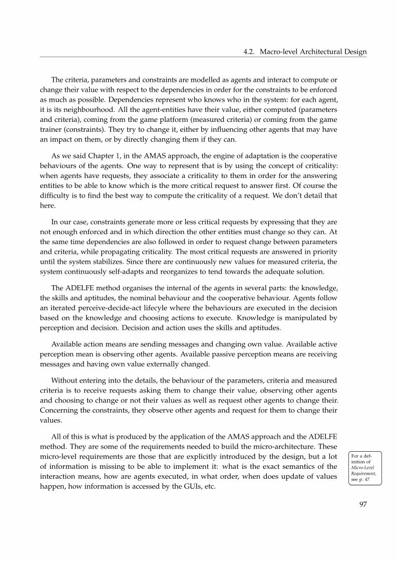
4.2. Macro-level Architectural Design
The criteria, parameters and constraints are modelled as agents and interact to compute orchange their value with respect to the dependencies in order for the constraints to be enforcedas much as possible. Dependencies represent who knows who in the system: for each agent,it is its neighbourhood. All the agent-entities have their value, either computed (parametersand criteria), coming from the game platform (measured criteria) or coming from the gametrainer (constraints). They try to change it, either by influencing other agents that may havean impact on them, or by directly changing them if they can.
As we said Chapter 1, in the AMAS approach, the engine of adaptation is the cooperativebehaviours of the agents. One way to represent that is by using the concept of criticality:when agents have requests, they associate a criticality to them in order for the answeringentities to be able to know which is the more critical request to answer first. Of course thedifficulty is to find the best way to compute the criticality of a request. We don’t detail thathere.
In our case, constraints generate more or less critical requests by expressing that they arenot enough enforced and in which direction the other entities must change so they can. Atthe same time dependencies are also followed in order to request change between parametersand criteria, while propagating criticality. The most critical requests are answered in priorityuntil the system stabilizes. Since there are continuously new values for measured criteria, thesystem continuously self-adapts and reorganizes to tend towards the adequate solution.
The ADELFE method organises the internal of the agents in several parts: the knowledge,the skills and aptitudes, the nominal behaviour and the cooperative behaviour. Agents followan iterated perceive-decide-act lifecyle where the behaviours are executed in the decisionbased on the knowledge and choosing actions to execute. Knowledge is manipulated byperception and decision. Decision and action uses the skills and aptitudes.
Available action means are sending messages and changing own value. Available activeperception mean is observing other agents. Available passive perception means are receivingmessages and having own value externally changed.
Without entering into the details, the behaviour of the parameters, criteria and measuredcriteria is to receive requests asking them to change their value, observing other agentsand choosing to change or not their values as well as request other agents to change their.Concerning the constraints, they observe other agents and request for them to change theirvalues.
All of this is what is produced by the application of the AMAS approach and the ADELFEmethod. They are some of the requirements needed to build the micro-architecture. Thesemicro-level requirements are those that are explicitly introduced by the design, but a lot For a def-
inition ofMicro-LevelRequirement,see p. 47
For a def-inition ofMicro-LevelRequirement,see p. 47
of information is missing to be able to implement it: what is the exact semantics of theinteraction means, how are agents executed, in what order, when does update of valueshappen, how information is accessed by the GUIs, etc.
97
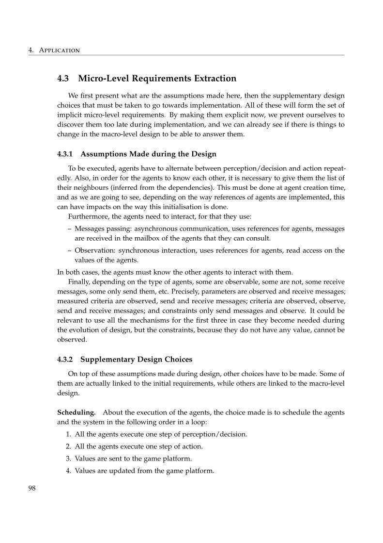
4. Application
4.3 Micro-Level Requirements Extraction
We first present what are the assumptions made here, then the supplementary designchoices that must be taken to go towards implementation. All of these will form the set ofimplicit micro-level requirements. By making them explicit now, we prevent ourselves todiscover them too late during implementation, and we can already see if there is things tochange in the macro-level design to be able to answer them.
4.3.1 Assumptions Made during the Design
To be executed, agents have to alternate between perception/decision and action repeat-edly. Also, in order for the agents to know each other, it is necessary to give them the list oftheir neighbours (inferred from the dependencies). This must be done at agent creation time,and as we are going to see, depending on the way references of agents are implemented, thiscan have impacts on the way this initialisation is done.
Furthermore, the agents need to interact, for that they use:
– Messages passing: asynchronous communication, uses references for agents, messagesare received in the mailbox of the agents that they can consult.
– Observation: synchronous interaction, uses references for agents, read access on thevalues of the agents.
In both cases, the agents must know the other agents to interact with them.Finally, depending on the type of agents, some are observable, some are not, some receive
messages, some only send them, etc. Precisely, parameters are observed and receive messages;measured criteria are observed, send and receive messages; criteria are observed, observe,send and receive messages; and constraints only send messages and observe. It could berelevant to use all the mechanisms for the first three in case they become needed duringthe evolution of design, but the constraints, because they do not have any value, cannot beobserved.
4.3.2 Supplementary Design Choices
On top of these assumptions made during design, other choices have to be made. Some ofthem are actually linked to the initial requirements, while others are linked to the macro-leveldesign.
Scheduling. About the execution of the agents, the choice made is to schedule the agentsand the system in the following order in a loop:
1. All the agents execute one step of perception/decision.
2. All the agents execute one step of action.
3. Values are sent to the game platform.
4. Values are updated from the game platform.
98
4.4. Micro-Level Architectural Design
This is needed because the macro-level design relies on the fact that no action is appliedbefore every agent has taken a decision.
Game Trainer GUI. The GUI used by the game trainer to modify the system in real timeonly interacts with the system to get and update values. The way the GUI manipulates thevalues is directly through the references of the entities objects encapsulated by the agentswithout any decoupling. This GUI is also responsible for triggering the sending of the newscenario to the game platform.
Tuning GUI. In AMAS, the driver of the adaptation being the criticality, in term of tuning,it is necessary to have an easy way of visualising the state of criticality of the agents and ofthe system (which is the maximum of the criticality of every agents). This means that weneed a GUI that shows that information on top of the entities values. This GUI must be easilyremovable from the system.
4.4 Micro-Level Architectural Design
Based on all these design choices and requirements, which form the set of micro-requirements, we can now design the micro-architecture of the system. From this set, we For a defini-
tion of Micro-Level Architec-tural View, seep. 47
For a defini-tion of Micro-Level Architec-tural View, seep. 47
extract precise specifications of the types of agents and their requirements for implementation.In particular we categorise the requirements as business or operative. They will drive the
For a defini-tion of Busi-ness and Oper-ative Require-ments, seep. 49
For a defini-tion of Busi-ness and Oper-ative Require-ments, seep. 49
building of the partially abstract micro-architecture so that it is easily usable by the MASdeveloper to work on his MAS design.
4.4.1 Operative Requirements
Different GUIs have to be integrated with the system: for tuning and for the game trainerinteractions. The first one has to be removable and needs access to internal values fromthe agents, the second one only needs access to the domain entities that are shared andencapsulated by the agents.
Interactions with the game platform must be doable through the network and should thusbe decoupled as much as possible from the system execution. They only concern the domainentities encapsulated by the agents.
The system is synchronised; the agents’ execution and the updates of values are alterna-tively executed by the platform:
– Update of values must be buffered before they can be sent to agents.
– Agents must be externally triggered by the platform.
– Their behaviour must be separated in two different steps.
The initialisation of the system must inject in the agents their list of neighbours.
99
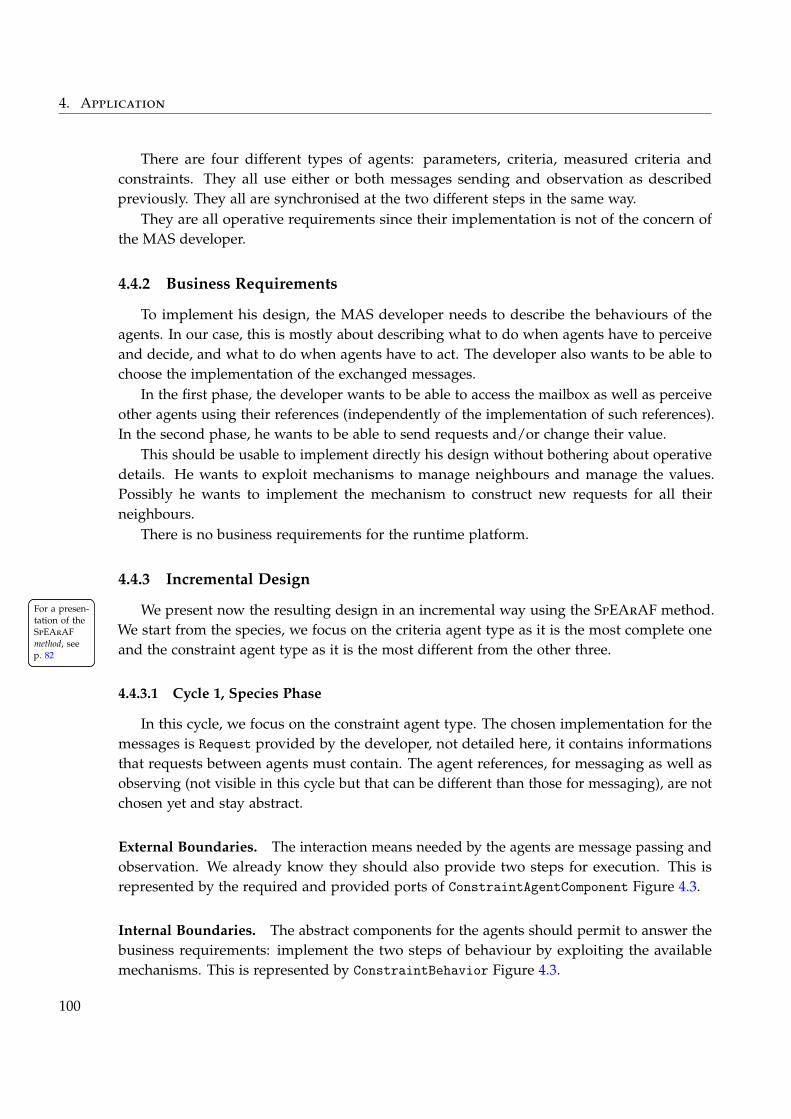
4. Application
There are four different types of agents: parameters, criteria, measured criteria andconstraints. They all use either or both messages sending and observation as describedpreviously. They all are synchronised at the two different steps in the same way.
They are all operative requirements since their implementation is not of the concern ofthe MAS developer.
4.4.2 Business Requirements
To implement his design, the MAS developer needs to describe the behaviours of theagents. In our case, this is mostly about describing what to do when agents have to perceiveand decide, and what to do when agents have to act. The developer also wants to be able tochoose the implementation of the exchanged messages.
In the first phase, the developer wants to be able to access the mailbox as well as perceiveother agents using their references (independently of the implementation of such references).In the second phase, he wants to be able to send requests and/or change their value.
This should be usable to implement directly his design without bothering about operativedetails. He wants to exploit mechanisms to manage neighbours and manage the values.Possibly he wants to implement the mechanism to construct new requests for all theirneighbours.
There is no business requirements for the runtime platform.
4.4.3 Incremental Design
We present now the resulting design in an incremental way using the SpEArAF method.For a presen-tation of theSpEArAFmethod, seep. 82
For a presen-tation of theSpEArAFmethod, seep. 82
We start from the species, we focus on the criteria agent type as it is the most complete oneand the constraint agent type as it is the most different from the other three.
4.4.3.1 Cycle 1, Species Phase
In this cycle, we focus on the constraint agent type. The chosen implementation for themessages is Request provided by the developer, not detailed here, it contains informationsthat requests between agents must contain. The agent references, for messaging as well asobserving (not visible in this cycle but that can be different than those for messaging), are notchosen yet and stay abstract.
External Boundaries. The interaction means needed by the agents are message passing andobservation. We already know they should also provide two steps for execution. This isrepresented by the required and provided ports of ConstraintAgentComponent Figure 4.3.
Internal Boundaries. The abstract components for the agents should permit to answer thebusiness requirements: implement the two steps of behaviour by exploiting the availablemechanisms. This is represented by ConstraintBehavior Figure 4.3.
100
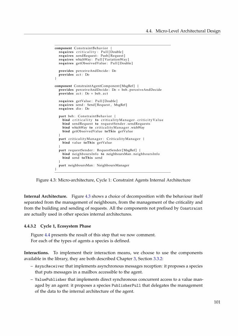
4.4. Micro-Level Architectural Design
component Constra intBehavior {requires c r i t i c a l i t y : Pul l [ Double ]requires sendRequest : Push [ Request ]requires whichWay : Pul l [ VariationWay ]requires getObservedValue : Pul l [ Double ]
provides perceiveAndDecide : Doprovides a c t : Do
}
component ConstraintAgentComponent [ MsgRef ] {provides perceiveAndDecide : Do = beh . perceiveAndDecideprovides a c t : Do = beh . a c t
requires getValue : Pul l [ Double ]requires send : Send [ Request , MsgRef ]requires die : Do
part beh : Constra intBehavior {bind c r i t i c a l i t y to c r i t i c a l i t y M a n a g e r . c r i t i c i t y V a l u ebind sendRequest to requestSender . sendRequestsbind whichWay to c r i t i c a l i t y M a n a g e r . wichWaybind getObservedValue toThis getValue
}part c r i t i c a l i t y M a n a g e r : C r i t i c a l i t y M a n a g e r {
bind value toThis getValue}part requestSender : RequestSender [ MsgRef ] {
bind neighboursInfo to neighboursMan . neighboursInfobind send toThis send
}part neighboursMan : NeighboursManager
}
Figure 4.3: Micro-architecture, Cycle 1: Constraint Agents Internal Architecture
Internal Architecture. Figure 4.3 shows a choice of decomposition with the behaviour itselfseparated from the management of neighbours, from the management of the criticality andfrom the building and sending of requests. All the components not prefixed by Constraintare actually used in other species internal architectures.
4.4.3.2 Cycle 1, Ecosystem Phase
Figure 4.4 presents the result of this step that we now comment.For each of the types of agents a species is defined.
Interactions. To implement their interaction means, we choose to use the componentsavailable in the library, they are both described Chapter 3, Section 3.3.2:
– AsyncReceiver that implements asynchronous messages reception: it proposes a speciesthat puts messages in a mailbox accessible to the agent.
– ValuePublisher that implements direct synchronous concurrent access to a value man-aged by an agent: it proposes a species PublisherPull that delegates the managementof the data to the internal architecture of the agent.
101
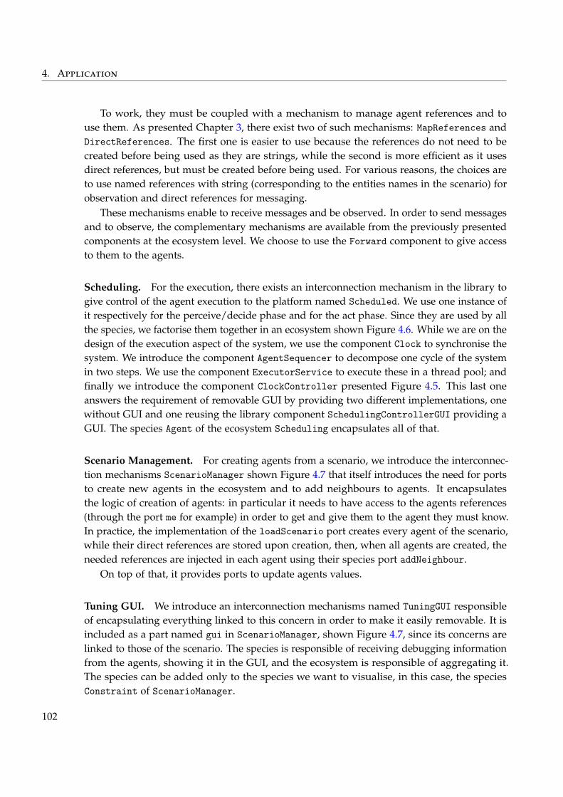
4. Application
To work, they must be coupled with a mechanism to manage agent references and touse them. As presented Chapter 3, there exist two of such mechanisms: MapReferences andDirectReferences. The first one is easier to use because the references do not need to becreated before being used as they are strings, while the second is more efficient as it usesdirect references, but must be created before being used. For various reasons, the choices areto use named references with string (corresponding to the entities names in the scenario) forobservation and direct references for messaging.
These mechanisms enable to receive messages and be observed. In order to send messagesand to observe, the complementary mechanisms are available from the previously presentedcomponents at the ecosystem level. We choose to use the Forward component to give accessto them to the agents.
Scheduling. For the execution, there exists an interconnection mechanism in the library togive control of the agent execution to the platform named Scheduled. We use one instance ofit respectively for the perceive/decide phase and for the act phase. Since they are used by allthe species, we factorise them together in an ecosystem shown Figure 4.6. While we are on thedesign of the execution aspect of the system, we use the component Clock to synchronise thesystem. We introduce the component AgentSequencer to decompose one cycle of the systemin two steps. We use the component ExecutorService to execute these in a thread pool; andfinally we introduce the component ClockController presented Figure 4.5. This last oneanswers the requirement of removable GUI by providing two different implementations, onewithout GUI and one reusing the library component SchedulingControllerGUI providing aGUI. The species Agent of the ecosystem Scheduling encapsulates all of that.
Scenario Management. For creating agents from a scenario, we introduce the interconnec-tion mechanisms ScenarioManager shown Figure 4.7 that itself introduces the need for portsto create new agents in the ecosystem and to add neighbours to agents. It encapsulatesthe logic of creation of agents: in particular it needs to have access to the agents references(through the port me for example) in order to get and give them to the agent they must know.In practice, the implementation of the loadScenario port creates every agent of the scenario,while their direct references are stored upon creation, then, when all agents are created, theneeded references are injected in each agent using their species port addNeighbour.
On top of that, it provides ports to update agents values.
Tuning GUI. We introduce an interconnection mechanisms named TuningGUI responsibleof encapsulating everything linked to this concern in order to make it easily removable. It isincluded as a part named gui in ScenarioManager, shown Figure 4.7, since its concerns arelinked to those of the scenario. The species is responsible of receiving debugging informationfrom the agents, showing it in the GUI, and the ecosystem is responsible of aggregating it.The species can be added only to the species we want to visualise, in this case, the speciesConstraint of ScenarioManager.
102
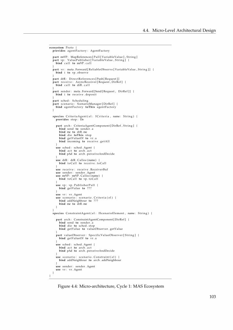
4.4. Micro-Level Architectural Design
ecosystem Proto {provides agentFactory : AgentFactory
part mrVP : MapReferences [ Pul l [ VariableValue ] , S t r i n g ]part vp : ValuePublisher [ VariableValue , S t r i n g ] {
bind c a l l to mrVP . c a l l}part vr : meta . Forward [ Rel iableObserve [ VariableValue , S t r i n g ] ] {
bind i to vp . observe}part drR : Dir ec tR efer ence s [ Push [ Request ] ]part r e c e i v e : AsyncReceiver [ Request , DirRef ] {
bind c a l l to drR . c a l l}part sender : meta . Forward [ Send [ Request , DirRef ] ] {
bind i to r e c e i v e . deposi t}part sched : Schedulingpart s c e n a r i o : ScenarioManager [ DirRef ] {
bind agentFactory toThis agentFactory}
species Cri ter iaAgent ( e l : I C r i t e r i a , name : S t r i n g ) {provides stop : Do
part arch : CriteriaAgentComponent [ DirRef , S t r i n g ] {bind send to sender . abind me to drR .mebind die toThis stopbind getValueOf to vr . abind incoming to r e c e i v e . g e t A l l
}use sched : sched . Agent {
bind a c t to arch . a c tbind pAd to arch . perceiveAndDecide
}use drR : drR . Cal lee (name) {
bind t o C a l l to r e c e i v e . t o C a l l}use r e c e i v e : r e c e i v e . ReceiverBufuse sender : sender . Agentuse mrVP : mrVP . Cal lee (name) {
bind t o C a l l to vp . t o C a l l}use vp : vp . P u b l i s h e r P u l l {
bind getValue to ???}use vr : vr . Agentuse s c e n a r i o : s c e n a r i o . C r i t e r i a ( e l ) {
bind addNeighbour to ???bind me to drR .me
}}species ConstraintAgent ( e l : IScenarioElement , name : S t r i n g ) {
part arch : ConstraintAgentComponent [ DirRef ] {bind send to sender . abind die to sched . stopbind getValue to valueObserver . getValue
}part valueObserver : Speci f icValueObserver [ S t r i n g ] {
bind getValueOf to vr . a}use sched : sched . Agent {
bind a c t to arch . a c tbind pAd to arch . perceiveAndDecide
}use s c e n a r i o : s c e n a r i o . Constra int ( e l ) {
bind addNeighbour to arch . addNeighbour}use sender : sender . Agentuse vr : vr . Agent
}}
Figure 4.4: Micro-architecture, Cycle 1: MAS Ecosystem
103
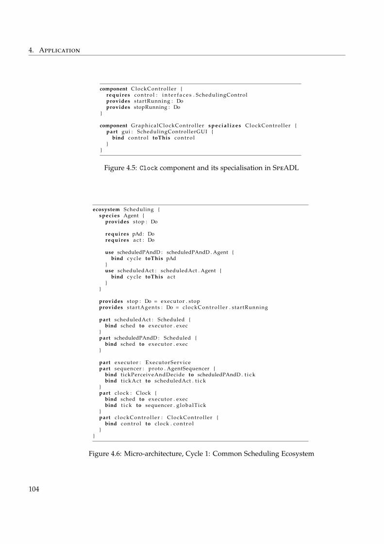
4. Application
component ClockContro l ler {requires c o n t r o l : i n t e r f a c e s . SchedulingControlprovides startRunning : Doprovides stopRunning : Do
}
component Graphica lClockContro l ler s p e c i a l i z e s ClockContro l ler {part gui : SchedulingControllerGUI {
bind c o n t r o l toThis c o n t r o l}
}
Figure 4.5: Clock component and its specialisation in SpeADL
ecosystem Scheduling {species Agent {
provides stop : Do
requires pAd : Dorequires a c t : Do
use scheduledPAndD : scheduledPAndD . Agent {bind c y c l e toThis pAd
}use scheduledAct : scheduledAct . Agent {
bind c y c l e toThis a c t}
}
provides stop : Do = executor . stopprovides s tar tAgents : Do = c l o c k C o n t r o l l e r . startRunning
part scheduledAct : Scheduled {bind sched to executor . exec
}part scheduledPAndD : Scheduled {
bind sched to executor . exec}
part executor : ExecutorServ icepart sequencer : proto . AgentSequencer {
bind t ickPerceiveAndDecide to scheduledPAndD . t i c kbind t i c k A c t to scheduledAct . t i c k
}part c lock : Clock {
bind sched to executor . execbind t i c k to sequencer . g loba lT ick
}part c l o c k C o n t r o l l e r : ClockContro l ler {
bind c o n t r o l to c lock . c o n t r o l}
}
Figure 4.6: Micro-architecture, Cycle 1: Common Scheduling Ecosystem
104
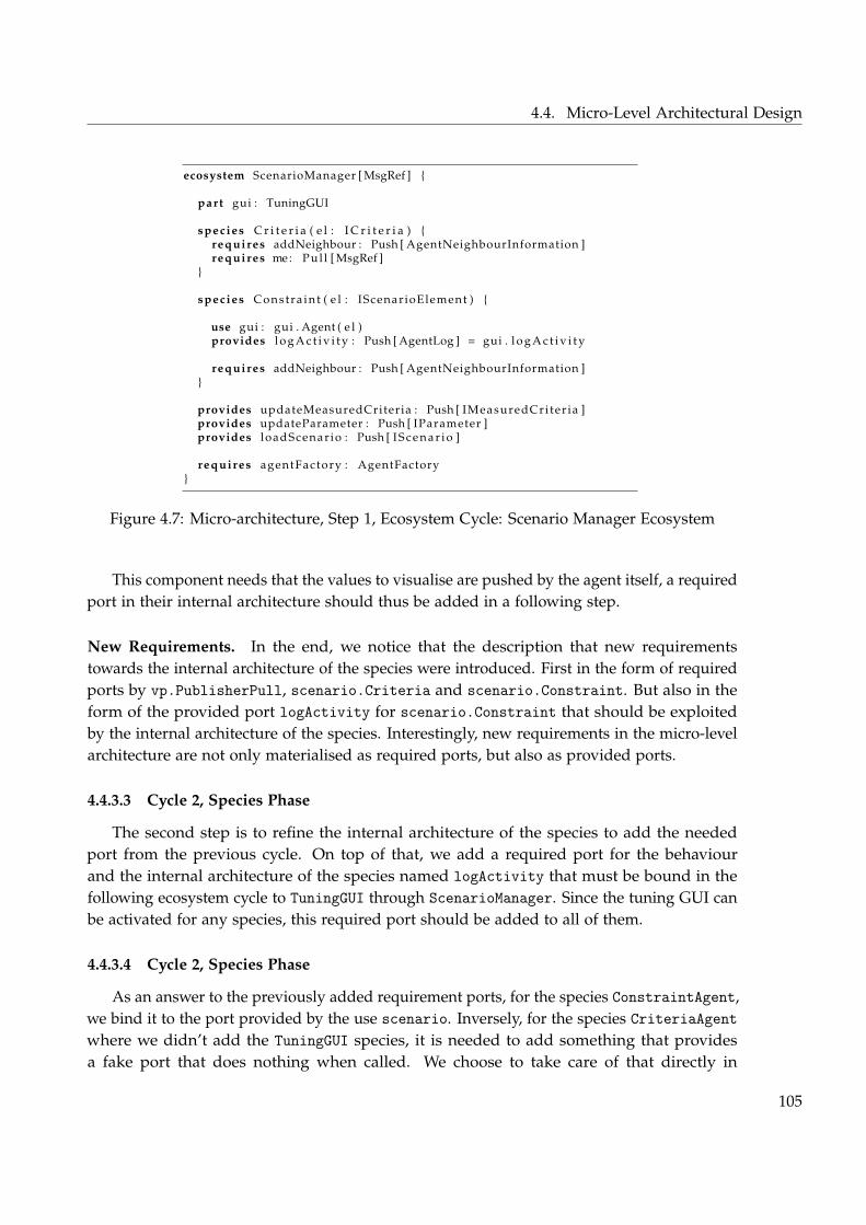
4.4. Micro-Level Architectural Design
ecosystem ScenarioManager [ MsgRef ] {
part gui : TuningGUI
species C r i t e r i a ( e l : I C r i t e r i a ) {requires addNeighbour : Push [ AgentNeighbourInformation ]requires me: Pul l [ MsgRef ]
}
species Constra int ( e l : IScenarioElement ) {
use gui : gui . Agent ( e l )provides l o g A c t i v i t y : Push [ AgentLog ] = gui . l o g A c t i v i t y
requires addNeighbour : Push [ AgentNeighbourInformation ]}
provides updateMeasuredCriteria : Push [ IMeasuredCri ter ia ]provides updateParameter : Push [ IParameter ]provides loadScenar io : Push [ I S c e n a r i o ]
requires agentFactory : AgentFactory}
Figure 4.7: Micro-architecture, Step 1, Ecosystem Cycle: Scenario Manager Ecosystem
This component needs that the values to visualise are pushed by the agent itself, a requiredport in their internal architecture should thus be added in a following step.
New Requirements. In the end, we notice that the description that new requirementstowards the internal architecture of the species were introduced. First in the form of requiredports by vp.PublisherPull, scenario.Criteria and scenario.Constraint. But also in theform of the provided port logActivity for scenario.Constraint that should be exploitedby the internal architecture of the species. Interestingly, new requirements in the micro-levelarchitecture are not only materialised as required ports, but also as provided ports.
4.4.3.3 Cycle 2, Species Phase
The second step is to refine the internal architecture of the species to add the neededport from the previous cycle. On top of that, we add a required port for the behaviourand the internal architecture of the species named logActivity that must be bound in thefollowing ecosystem cycle to TuningGUI through ScenarioManager. Since the tuning GUI canbe activated for any species, this required port should be added to all of them.
4.4.3.4 Cycle 2, Species Phase
As an answer to the previously added requirement ports, for the species ConstraintAgent,we bind it to the port provided by the use scenario. Inversely, for the species CriteriaAgentwhere we didn’t add the TuningGUI species, it is needed to add something that providesa fake port that does nothing when called. We choose to take care of that directly in
105
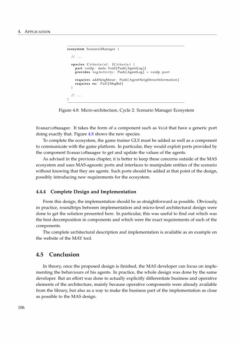
4. Application
ecosystem ScenarioManager {
/ / . . .
species C r i t e r i a ( e l : I C r i t e r i a ) {part voidp : meta . Void [ Push [ AgentLog ] ]provides l o g A c t i v i t y : Push [ AgentLog ] = voidp . port
requires addNeighbour : Push [ AgentNeighbourInformation ]requires me: Pul l [ MsgRef ]
}
/ / . . .}
Figure 4.8: Micro-architecture, Cycle 2: Scenario Manager Ecosystem
ScenarioManager. It takes the form of a component such as Void that have a generic portdoing exactly that. Figure 4.8 shows the new species.
To complete the ecosystem, the game trainer GUI must be added as well as a componentto communicate with the game platform. In particular, they would exploit ports provided bythe component ScenarioManager to get and update the values of the agents.
As advised in the previous chapter, it is better to keep these concerns outside of the MASecosystem and uses MAS-agnostic ports and interfaces to manipulate entities of the scenariowithout knowing that they are agents. Such ports should be added at that point of the design,possibly introducing new requirements for the ecosystem.
4.4.4 Complete Design and Implementation
From this design, the implementation should be as straightforward as possible. Obviously,in practice, roundtrips between implementation and micro-level architectural design weredone to get the solution presented here. In particular, this was useful to find out which wasthe best decomposition in components and which were the exact requirements of each of thecomponents.
The complete architectural description and implementation is available as an example onthe website of the MAY tool.
4.5 Conclusion
In theory, once the proposed design is finished, the MAS developer can focus on imple-menting the behaviours of his agents. In practice, the whole design was done by the samedeveloper. But an effort was done to actually explicitly differentiate business and operativeelements of the architecture, mainly because operative components were already availablefrom the library, but also as a way to make the business part of the implementation as closeas possible to the MAS design.
106
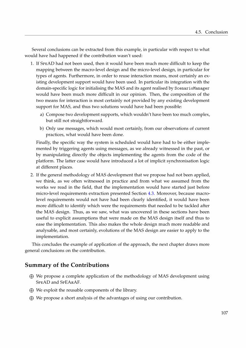
4.5. Conclusion
Several conclusions can be extracted from this example, in particular with respect to whatwould have had happened if the contribution wasn’t used:
1. If SpeAD had not been used, then it would have been much more difficult to keep themapping between the macro-level design and the micro-level design, in particular fortypes of agents. Furthermore, in order to reuse interaction means, most certainly an ex-isting development support would have been used. In particular its integration with thedomain-specific logic for initialising the MAS and its agent realised by ScenarioManagerwould have been much more difficult in our opinion. Then, the composition of thetwo means for interaction is most certainly not provided by any existing developmentsupport for MAS, and thus two solutions would have had been possible:
a) Compose two development supports, which wouldn’t have been too much complex,but still not straightforward.
b) Only use messages, which would most certainly, from our observations of currentpractices, what would have been done.
Finally, the specific way the system is scheduled would have had to be either imple-mented by triggering agents using messages, as we already witnessed in the past, orby manipulating directly the objects implementing the agents from the code of theplatform. The latter case would have introduced a lot of implicit synchronisation logicat different places.
2. If the general methodology of MAS development that we propose had not been applied,we think, as we often witnessed in practice and from what we assumed from theworks we read in the field, that the implementation would have started just beforemicro-level requirements extraction presented Section 4.3. Moreover, because macro-level requirements would not have had been clearly identified, it would have beenmore difficult to identify which were the requirements that needed to be tackled afterthe MAS design. Thus, as we saw, what was uncovered in these sections have beenuseful to explicit assumptions that were made on the MAS design itself and thus toease the implementation. This also makes the whole design much more readable andanalysable, and most certainly, evolutions of the MAS design are easier to apply to theimplementation.
This concludes the example of application of the approach, the next chapter draws moregeneral conclusions on the contribution.
Summary of the Contributions⊕We propose a complete application of the methodology of MAS development usingSpeAD and SpEArAF.⊕We exploit the reusable components of the library.⊕We propose a short analysis of the advantages of using our contribution.
107

CHAPTER 5Positioning, Analysis and
Experimental Feedbacks
In this chapter, we present an analysis of the contribution presented Chapter 3 and Chap-ter 4. We position the whole contribution and the example with respect to the classificationof the works presented Chapter 2. Then, we present how the contribution and in particularthe proposed component model answers the challenges identified Chapter 2. This analysisis discussed to extract the motivations and advantages of using our component model. Fi-nally, we present academic and industrial works that used our contribution and detail someexperimental feedbacks from our users.
5.1 Positioning the Contribution
Chapter 2, we presented a classification that presented six classes of research works about For a detailedpresentationof the Classi-fication, seep. 37
For a detailedpresentationof the Classi-fication, seep. 37
MAS development. On the other hand, our contribution is decomposable in elements, eachpotentially positionable in the classification. To that, we add the example as well as themethod used for its development. This gives us the following set of elements to position:
– The architecture-centric methodology, Section 3.1
– The SpeAD component model, Section 3.2
– The guidelines for capturing and reusing experiences, Section 3.3.1
– The library of components produced with SpeAD, Section 3.3.2
– The SpEArAF design method, Section 3.4
– The ADELFE method and the AMAS approach, Section 1.3.3
– The macro-level design of the VGD, Section 4.2
– The micro-level design of the VGD, Section 4.4
– The implementation of the VGD, Section 4.4.4
109
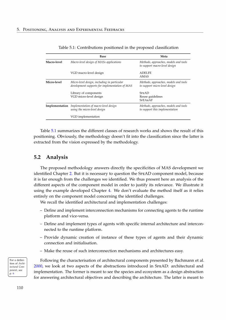
5. Positioning, Analysis and Experimental Feedbacks
Table 5.1: Contributions positioned in the proposed classification
Base Meta
Macro-level Macro-level design of MASs applications
VGD macro-level design
Methods, approaches, models and toolsto support macro-level design
ADELFEAMAS
Micro-level Micro-level design, including in particulardevelopment supports for implementation of MAS
Library of componentsVGD micro-level design
Methods, approaches, models and toolsto support micro-level design
SpeADReuse guidelinesSpEArAF
Implementation Implementation of macro-level designusing the micro-level design
VGD implementation
Methods, approaches, models and toolsto support this implementation
Table 5.1 summarizes the different classes of research works and shows the result of thispositioning. Obviously, the methodology doesn’t fit into the classification since the latter isextracted from the vision expressed by the methodology.
5.2 Analysis
The proposed methodology answers directly the specificities of MAS development weidentified Chapter 2. But it is necessary to question the SpeAD component model, becauseit is far enough from the challenges we identified. We thus present here an analysis of thedifferent aspects of the component model in order to justify its relevance. We illustrate itusing the example developed Chapter 4. We don’t evaluate the method itself as it reliesentirely on the component model concerning the identified challenges.
We recall the identified architectural and implementation challenges:
– Define and implement interconnection mechanisms for connecting agents to the runtimeplatform and vice-versa.
– Define and implement types of agents with specific internal architecture and intercon-nected to the runtime platform.
– Provide dynamic creation of instance of these types of agents and their dynamicconnection and initialisation.
– Make the reuse of such interconnection mechanisms and architectures easy.
Following the characterisation of architectural components presented by Bachmann et al.For a defini-tion of Archi-tectural Com-ponent, seep. 6
For a defini-tion of Archi-tectural Com-ponent, seep. 6
2000, we look at two aspects of the abstractions introduced in SpeAD: architectural andimplementation. The former is meant to see the species and ecosystem as a design abstractionfor answering architectural objectives and describing the architecture. The latter is meant to
110
5.2. Analysis
see the species and ecosystem as means of implementing component-based architectures withrespect to their role as architectural abstractions.
For both of these aspects, we look at two points of view: agents and interconnection. Thefirst one is about answering the need to realise types of agents, while the second one is aboutanswering the need to realise interaction and interconnection mechanisms. This gives usthe possibility to differentiate between a species in an ecosystem as a type of agents, and aspecies in a ecosystem as an architectural element located inside agents.
We focus on the MAS aspect of the solution and do not comment the possible advantageof the model for component-oriented programming.
5.2.1 Architectural Abstraction
From the agent point of view, species are first and foremost a way to explicit the typesof agents at the architectural level. Indeed, in MASs, it is obvious that having agents is animportant design choice and thus should be made explicit in the software architecture of thebuilt system. They explicit the existence of dynamically created entities that interact togetherusing specific interaction means. Furthermore, by doing so, the species drives the definitionof the rest of the architecture, i.e. the ecosystem and the species internal architectures. Italso helps to identify what must be in the agents or outside of them, what is going to beduplicated in every agent and what is centralised in the runtime platform.
From the interconnection point of view, obviously, species play the same role of makingexplicit the use of specific interaction mechanisms and the existence of needed links betweenthe agents and the runtime platform. In a way, such explicitly specified interconnectionmechanisms are a guarantee of the autonomy of the agents, which is an important feature ofthe MASs and often forgotten point during implementation. Indeed, when implementingMASs, it is easy to introduce runtime dependencies between what is inside the agents andwhat is in the platform: for example environment entities directly manipulating data in theagents, which could breaks the assumption made at design. Thus, by having species usespecies of their ecosystem parts, the places were the autonomy of the agents is threatened areclearly identified. The TuningGUI in the previous chapter is a good example of this: withoutsuch abstraction, the answer to this requirement would have most certainly be hidden inthe implementation of the system. This is particularly important also when implementingprototypes Furthermore, this abstraction enables to clearly identify reusable and composablecomponents realising recurring interconnection mechanisms. The examples of interconnectionmechanisms in the previous chapter are self-explaining.
Finally, the composition of these interconnection mechanisms in species to represent typesof agents act as a way to encapsulate the definition of a type of agents behind a clearlydefined interface. Indeed, everything not explicitly needed outside of the description of atype of agents does not have to filtrate out, and in particular not to the components thatwants to create new instances of agents. A good example of this is the status of the referenceof agents, which are used internally in the species as well as in the used species, but notneeded to create an agent. In particular, this separate the concern of creating an agent and
111
5. Positioning, Analysis and Experimental Feedbacks
implementing this creation. Indeed, they do not have to know how the agents that are createdare linked to the ecosystem and what is their internal architecture.
5.2.2 Implementation Abstraction
From the interconnection point of view, the species is a way to implement, either directlyor by composition of other species, a 1 − N link. It contains an implementation for the uniquepart, for the duplicated part, and more importantly for the initialisation of the latter. Indeed,by encapsulating the initialisation of new elements meant to exist in agents, it abstract overthe dynamic creation of these elements. Using the ports, it gives the possibility to explicitthe needed mechanisms to work with the other dynamically created elements of the speciesarchitecture. For example, the references mechanism composed with the messages receivingmechanism let the definition of the internal architecture be independent of the way thesemechanisms are realised. In a way, it is a mean to implement the functionality requiredby the internal architecture of agents by abstracting over their multiplicity. It is a way toimplement individual-centric mechanisms so that the user does not bother with questionsabout dynamicity or multiplicity. Again, TuningGUI is a good example of that.
From the agent point of view, the species allows to compose interconnection mechanisms.Describing which ones are used and how they are connected is enough to have a workingimplementation for the species. Moreover, it abstracts over the dynamic creation of instancesof the species as well as the creation of all of the species used. Furthermore, such compositionof interconnection mechanisms enables to easily add or remove elements from the specieswithout changing the rest of the system. This is well illustrated by the TuningGUI which iseasily removable.
In other words, what our model introduces are abstractions that are a way of realisinga kind of recurring pattern that answers the recurring problem of dynamically creatingand connecting entities to a platform. This is particularly interesting in the case of agentscreating other agents. Because the agent construction mechanisms is taken care in each ofthe interconnection mechanisms, composed together in an ecosystem through the definitionof a species and hidden behind a port definition, there is then no need to manage the factthat the creating entity is itself an agent that was created dynamically. Implementing suchthings using for example object-oriented abstractions is difficult because the links betweenthe created entity and the platform would have had to be handled by the creating entity.
5.2.3 Why and When to Use SpeAD
Thereby, ecosystem and species are seen as abstractions that are useful, in the context ofMASs, for expliciting architectural choices, enforcing them and implementing them. Eventhough this is of first importance for developing software in a realistic way, this does notcompletely justify the use of the specific component model proposed here for any kind ofapplications.
112
5.3. Experimental Applications and Users Feedbacks
Indeed, to build MASs, a lot of existing development supports provide means to connectagents together using a diversity of interconnection mechanisms. The precepts presented inthis thesis could be applied with these without reinventing these very common interconnectionmechanisms as we did in the previous chapters. This also questions the interest of building acomplete platform for every application. For a def-
inition ofAgent-BasedModelling, seep. 12
For a def-inition ofAgent-BasedModelling, seep. 12
But as we showed in the state of the art and with the example, there is sometimes the needfor building such interconnection mechanisms adapted to the MAS design. The TuningGUI,that we used a lot as an example in the previous section, is a good motivation: it shows adevelopment-specific requirements answered easily thanks to the abstractions. This pointalso manifests itself in ABM (Agent-Based Modelling), which is one of the type of MASs weare particularly interested in. Indeed, for this class of application, the MAS design is stronglyinfluenced by the domain model.
In all these situations, our model provides what is needed to build such adapted inter-connection mechanisms. But even more importantly, it makes possible to compose them in acoherent and adapted way, while at the same time making such mechanisms reusable. Fromour point of view, this last point is maybe the most challenging technical objective that themodel answers.
Thus, coupled with the need for following software architecture principles, all of thisjustify the need for starting back from a cleaner and clearer development model for MASengineering.
5.3 Experimental Applications and Users Feedbacks
We now present the different academic and industrial works that used our tools andapproaches, and present some feedbacks we got.
Our contribution was mainly applied internally in the SMAC research team, but also inthe UPETEC start-up company. For a pre-
sentation ofSMAC andUPETEC, seep. xxii
For a pre-sentation ofSMAC andUPETEC, seep. xxii
As it was said in the introduction, our contribution has been been published in twoversions before we ended up with the contribution in this thesis. For each of these, wereleased tools, mainly focused on component-based engineering for agents and MASs. Thesetools promoted the use of the methodological concerns we expressed in this thesis.
The first version of the contribution (Noël, Arcangeli, and Gleizes 2010a; Noël, Arcangeli,and Gleizes 2010b) is mainly focused on the methodological separation between macro-architectural design and micro-architectural design with a tool that supported the definitionof component-based internal agent architectures. The tool was used in several works andprojects with industrial partners such as:
– Biological simulation (Bonjean, Bernon, and Glize 2009).
– Dynamic ontology construction (Sellami and Camps 2012) in the context of the nationalDYNAMO 1 project.
1. DYNAMic Ontology for information retrieval: http://www.irit.fr/dynamo/
113
5. Positioning, Analysis and Experimental Feedbacks
– Naval surveillance (Georgé et al. 2009) in the context of the national SISMARIS 2 project.
– Self-organising team of robots self-allocating tasks (Lacouture, Noël, et al. 2011) in thecontext of the regional ROSACE 3 project.
– Distributed constraint optimization (Kaddoum 2011).
– Cabling optimisation for planes in the context of the regional SMART 4 project.
Then, the second version of the contribution (Noël and Arcangeli 2011; Noël, Arcangeli,and Gleizes 2012) introduced the species and ecosystem components abstractions. It is veryclose to what is presented here and is fully compatible with it. This version of the contributionis broadly and currently used: the tool implementing it is the current main and most stableversion of it. In particular, it was used:
– In the context of research projects with industrial partners such as the ID4CS 5, GAM-BITS 6, ORIANNE 7.
– By Ph.D. students of the team in applications such as dynamic management of contextin ambient systems (Guivarch, Camps, and Péninou 2012), self-composed methodfragments (Bonjean et al. 2012), adaptive combustion motor calibration, adaptive energyregulation, multi-disciplinary constraint optimization, etc.
– By a Master student during its internship that resulted in the system for opportunisticself-composition of ambient components (Denis et al. 2012) presented Chapter 7.
– To introduce component-based programming to Master students.
– In the context of a Master student project for university schedule timetabling usingMASs.
Moreover our methodology of MAS development was used to organise the development ofthe system for dynamic workflow adaptation (Cruz Torres et al. 2010b; Cruz Torres et al.2010a) presented Chapter 7.
It would have been interesting to do an evaluation, with our users, of the proposedcontribution, of its implementation itself and of the systems that were produced using it.Unfortunately, this has not been possible, but
The general feedback is positive, once a time of learning has passed. Indeed, theyall are discovering software architectures as a design approach and component-orientedprogramming as an implementation approach.
The main advantages expressed by the users are about reuse and maintenance. The libraryof components along with the help of people (including us) familiar with the approach are
2. Système d’Information et de Surveillance MARitime pour l’Identification des comportements Suspect:http://www.sismaris.org/
3. RObots et Systèmes Auto-adaptatifs Communicants Embarqués: http://www.irit.fr/Rosace,7374. SMart-hARness Technologies: http://www.irit.fr/SMART,11785. Integrative Design for Complex Systems: http://www.irit.fr/id4cs/6. GAMe-Based IntelligenT Strategie: http://www.gambits.fr/7. Outil numéRIque pour le mAquettage de foNctions de coNtrôle motEur: http://www.irit.fr/ORIANNE,
1176
114
5.4. Conclusion
very useful in starting a new application. Once people have a working base, they becomemore independent and build their software on top of it. For example, we got a feedback ofsomeone happy to be able to easily change the way their system was scheduled with as littleactions as possible. Or another told us they built their own set of reusable components forrapid prototyping and debugging.
Concerning teaching, the tool was well accepted in the classroom and proved to be robustenough to pass the “student crashtest”.
5.4 Conclusion
We presented a positioning of the contribution with respect to other works for MASdevelopment. We draw an analysis from which we drew a conclusion on the advantages ofusing our component model. We presented the academic and industrial works that appliedour approaches and used our tools.
From all of that we concluded that what we propose in this first part of the thesis is usefulto MAS development and positively accepted by people that actually design and implementMASs. We are confident, from the feedbacks we got from them, that the tools we gave themhelped them in producing better software.
As a conclusion, we also have the feeling, through our observations, that applying themethodological aspects of our approach helps the design of MASs itself. Indeed, by applyingsuch software architecture principles to the development of a MAS-based application, itclarifies what is the MAS really answering and what relations it has to the rest of the softwarebeing built. Even if it is most certainly too soon to conclude that, in our opinion, all of thisis particularly useful when presenting results to other researchers that are familiar with thework we do in the team.
We also take this opportunity to raise the attention on research works published latelyin notorious interdisciplinary journal (Ince, Hatton, and Graham-Cumming 2012; Morinet al. 2012). They argue that systematically making the implementation freely available withresearch papers would be beneficial to the research community. We think that our contributiongoes towards such objective for the following reasons:
– It makes the design and the implementation of MASs much more accessible to externalobservers by emphasising on architectural documentation.
– It proposes a frame to which the diverse people can refer to when talking about MASsas a software.
– It makes reuse and sharing in the community easier.
Summary of the Contributions⊕
We position the contribution as well as the produced software artefacts in the classifica-tion presented Chapter 2.
115

5. Positioning, Analysis and Experimental Feedbacks
⊕We analyse the contribution with respect to the architectural and implementation chal-lenges identified Chapter 2 using a recognized frame of characterisation for architecturalcomponents.⊕We show that the contribution was used in many different works and that we gotpositive feedbacks about it.
116
Part II
I N T E G R AT I N G M U LT I - A G E N T S Y S T E M S A N D S O F T WA R EA R C H I T E C T U R E S

CHAPTER 6MASs and CBSAs Side by Side:
Component-based ComponentContainers
More is not better (or worse)than less, just different.
The paradigm paradoxPeter Van Roy (2004)
In this chapter, we look back at the proposed approach of producing dedicated develop-ment support and at the SpeAD component model from the point of view of the softwarearchitecture field. Indeed, even though the contribution of this thesis is inspired by manyworks from a diversity of fields, its main innovations are at first only meant to answer thechallenges identified Chapter 2. The contribution of the first part of this thesis — namelythe definition of partially abstract component-based architectures to produce developmentsupports dedicated to applications and the definition of explicit dynamically created entitiesconnected to a runtime platform — can thus now be positioned with respect to existing worksto see in which points they are alike or different.
All of this brings us to reinterpret the contribution with respect to component modelsand containers, and all the works evolving around Component-Based Software Architectures(CBSAs). In particular we:
– revisit MASs design approaches as a family of architectural styles and design paradigms.
– reconsider MASs as components in CBSAs.
Based on that we show how SpeAD helps to achieve horizontal integration between MASsand components-based architectures and gives the possibility to software system designers tochoose and combine relevant design approaches when building applications.
119
6. MASs and CBSAs Side by Side: Component-based Component Containers
Secondarily to that, in order to reach this conclusion, we explore the relations that existbetween frameworks, components models, component containers, architectural patterns,architectural styles, architectures and components. This brings us to propose a way ofdefining and using dedicated component containers that can be implemented using SpeAD.
The content of this chapter is exploratory and mostly exists to draw some, in our opinioninteresting, axis of research on the general matter of design and implementation of devel-opment supports for the component-oriented development field. Although, some of theworks tackling such questions in that field try to get as formal as possible, here we onlyare manipulating abstract, and thus sometimes imprecise, concepts in order to reinterpretconcepts from the MAS field in the broader context of software architectures.
In a way the present chapter has a focus on the relations between architectural conceptsand MASs, but considering the latter at design, while next chapter considers MASs at runtime.
6.1 Related Works in the Software Architecture Field
6.1.1 Reusing High-Level Design
In this section, we first compare our work to Software Product Lines and then to object-oriented frameworks. We actually don’t rely on the ecosystem and species abstractions,but only on the idea of producing partially abstract architectures with component-orientedabstractions.
6.1.1.1 Software Product Line
One of the objectives of the contribution presented Part I is to reuse experience alongdifferent domains, applications, problems, etc, of MASs. In this sense, our work comeswithin the scope of Software Product Lines (SPLs) and ultimately could result in easing theFor a re-
minder onSoftware Prod-uct Lines, seep. 8
For a re-minder onSoftware Prod-uct Lines, seep. 8
development of SPLs for MASs.Nevertheless, while SPLs propose to define reusable architectures from which dedicated
architectures are built, our current contribution only focuses on the reuse of components tobuild dedicated architectures. From this point of view, the experience reused is only at thelevel of components and not architectures.
On the other hand, as we noted Chapter 3, it is possible to reuse design using templates.For a pre-sentation ofTemplate, seep. 69
For a pre-sentation ofTemplate, seep. 69
However, this approach has some shortcomings, which are mostly concerned with the SpeADcomponent model. Indeed, in its current state, it is not possible to specialise ecosystems norspecies. This thus means that the model is not able to represent reusable ecosystem withabstract components in the species.
For example, if building a MAS development support where the agents behaviours are leftopen, this would be represented with an ecosystem where the behaviours of the species areabstract components and where the implementation makes concrete all the other componentsof the ecosystem and the species. But it is not possible to use such an ecosystem and itsimplementation directly with concrete behaviours for the agents without modifying either
120
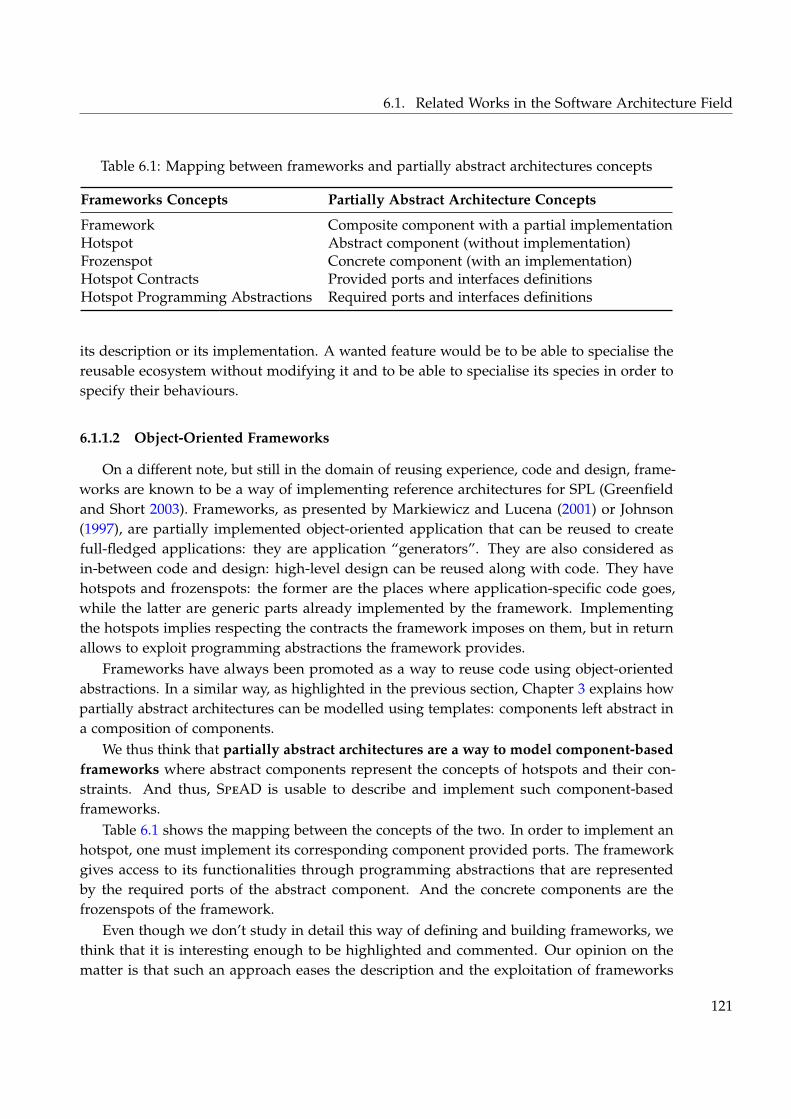
6.1. Related Works in the Software Architecture Field
Table 6.1: Mapping between frameworks and partially abstract architectures concepts
Frameworks Concepts Partially Abstract Architecture Concepts
Framework Composite component with a partial implementationHotspot Abstract component (without implementation)Frozenspot Concrete component (with an implementation)Hotspot Contracts Provided ports and interfaces definitionsHotspot Programming Abstractions Required ports and interfaces definitions
its description or its implementation. A wanted feature would be to be able to specialise thereusable ecosystem without modifying it and to be able to specialise its species in order tospecify their behaviours.
6.1.1.2 Object-Oriented Frameworks
On a different note, but still in the domain of reusing experience, code and design, frame-works are known to be a way of implementing reference architectures for SPL (Greenfieldand Short 2003). Frameworks, as presented by Markiewicz and Lucena (2001) or Johnson(1997), are partially implemented object-oriented application that can be reused to createfull-fledged applications: they are application “generators”. They are also considered asin-between code and design: high-level design can be reused along with code. They havehotspots and frozenspots: the former are the places where application-specific code goes,while the latter are generic parts already implemented by the framework. Implementingthe hotspots implies respecting the contracts the framework imposes on them, but in returnallows to exploit programming abstractions the framework provides.
Frameworks have always been promoted as a way to reuse code using object-orientedabstractions. In a similar way, as highlighted in the previous section, Chapter 3 explains howpartially abstract architectures can be modelled using templates: components left abstract ina composition of components.
We thus think that partially abstract architectures are a way to model component-basedframeworks where abstract components represent the concepts of hotspots and their con-straints. And thus, SpeAD is usable to describe and implement such component-basedframeworks.
Table 6.1 shows the mapping between the concepts of the two. In order to implement anhotspot, one must implement its corresponding component provided ports. The frameworkgives access to its functionalities through programming abstractions that are representedby the required ports of the abstract component. And the concrete components are thefrozenspots of the framework.
Even though we don’t study in detail this way of defining and building frameworks, wethink that it is interesting enough to be highlighted and commented. Our opinion on thematter is that such an approach eases the description and the exploitation of frameworks
121
6. MASs and CBSAs Side by Side: Component-based Component Containers
because:
– It uses explicit provided interfaces to define the hotspots.
– It uses explicit required interfaces to define the programming abstractions usable toprogram the hotpots.
– It takes the advantages of component-oriented abstractions for reuse and separation ofconcerns to build frameworks.
– It makes possible to more easily define hierarchically frameworks and compose themtogether.
To conclude on the last point, as it was coined in several works (Johnson 1997; Bachmannet al. 2000; Crnkovic et al. 2002), components and frameworks are conceptually reifiable inthe sense that frameworks are themselves usable as components and are at the same timecontainers for components. We think that our proposition of component-based frameworksmakes this feasible in practice with real component-oriented abstractions. Indeed, it is possiblewith it to describe frameworks that are themselves components, possibly with hotspots keptopen. They can thus be composed together in composites, but also used as the buildingblocks of other component-based frameworks. Obviously more studying should and mustbe done on the matter, first to ease the use of such approach, for example using SpeAD, butalso in the MAS field as SpeAD has limitations regarding partially abstract ecosystems andspecies.
6.1.2 Dynamic Component Creation and Connection
In this section, we look at the fact that SpeAD species are descriptions of classes ofcomponents and that these components instances can be created dynamically. We positionthis abstraction with those proposed in ADLs (Architecture Description Languages) andFor a re-
minder onArchitectureDescriptionLanguages, seep. 6
For a re-minder onArchitectureDescriptionLanguages, seep. 6
in more general programming languages. We focus on means to describe declarativelyand structurally how components can be dynamically created because for other means, ourcontribution does not radically differ.
In ADLs, a good example of such mean is the direct dynamic instantiation mechanismoffered by Darwin (Magee and Kramer 1996). We focus on this one since we consider it agood stereotype of what is generally provided in ADLs. In these works, the idea is that itis possible to describe that an element of an architecture can be dynamically instantiated byanother component. The latter triggers the creation of instances whenever it wants by usingthe mechanism provided by the component model. Both dynamically created componentsand creator components are at the same level in a composition.
In Darwin, dynamic component creation is triggered by other components that requiresa special type of port. In order to keep the architecture valid — i.e. that all required portsof components are connected to the provided port of another one — it is possible to definehow the instantiable type of component is connected to the rest of the architecture. AsDarwin authors point out, only the required ports connections of a dynamically instantiablecomponent can be described, as there wouldn’t be any way to describe how provided ports are
122
6.2. Relations between Component-based Architectural Concepts
connected (since this would mean requiring multiple provided ports). The way to alternativelydo that is to use what they call service references that bring down the concept of ports at theprogramming level and thus are not handled at the description level.
Inversely, with SpeAD, the relation between the created component — instance of aspecies — and the creating component — the ecosystem declaring the species — is the one ofcontained and containing. Thus, the dynamically created component is connected to the restof the world through its ecosystem, which, by the choice of uses of its parts in the species,constrains the way the instantiated component can interact with others. Obviously, this iscompletely different from what is done in traditional ADLs since the uses of the speciesdescribe the interaction means available to it and not just how it is connected. We come backon that point Section 6.4 to show what can be expressed with that.
Here, the important point is that we define how instances of species are created andconnected by relying on the semantics of their uses. This gives the possibility to be muchmore expressive than traditional ADLs, while guaranteeing that the composition is validby construction. In exchange, the point where uncertainty is present is the interconnectionmechanism, the use, and its semantics. We come back on that point Section 6.6 to discuss whyand how to use such solution instead of others.
When looking at component-oriented programming as an evolution of object-orientedprogramming, this resembles a lot non-static inner classes (Gosling et al. 2005) from object-oriented languages such as Java: these inner classes can only be instantiated from an existingobject. We can thus say that with species, we ported the inner class concept to component-oriented programming.
6.2 Relations between Component-based Architectural Concepts
In order to prepare to what is presented in the rest of this chapter, we now presentour vision of the relations existing between architectural concepts such as frameworks,components models, component containers, architectural patterns, architectural styles, ar-chitectures and components. As with the rest of the thesis and explained Chapter 1, weelude connectors. Moreover, in this section we completely put SpeAD aside.
Figure 6.1 illustrates such relations that we now detail. Next chapter comes back on theserelations in a runtime context in the next chapter.
Monroe et al. (1997) present styles as providing specialized design languages for specificclasses of systems. They define a set of authorised types of components and constraints thatan architecture must instantiate to be well-formed with respect to the style. But they can alsoconstrain and be instantiated by more abstract architectures expressed as patterns.
As presented by Bachmann et al. (2000), architectural styles and component models aresimilar in that they try to answer the same problems in the sense that they provide abstractionsadapted to a specific need. More precisely, it seems that architectural styles are more diverse,and that there exists a specialisation relation between them as defended by Fielding (2000). Weconsider that existing component models allow to express architectures that instantiates one or
123
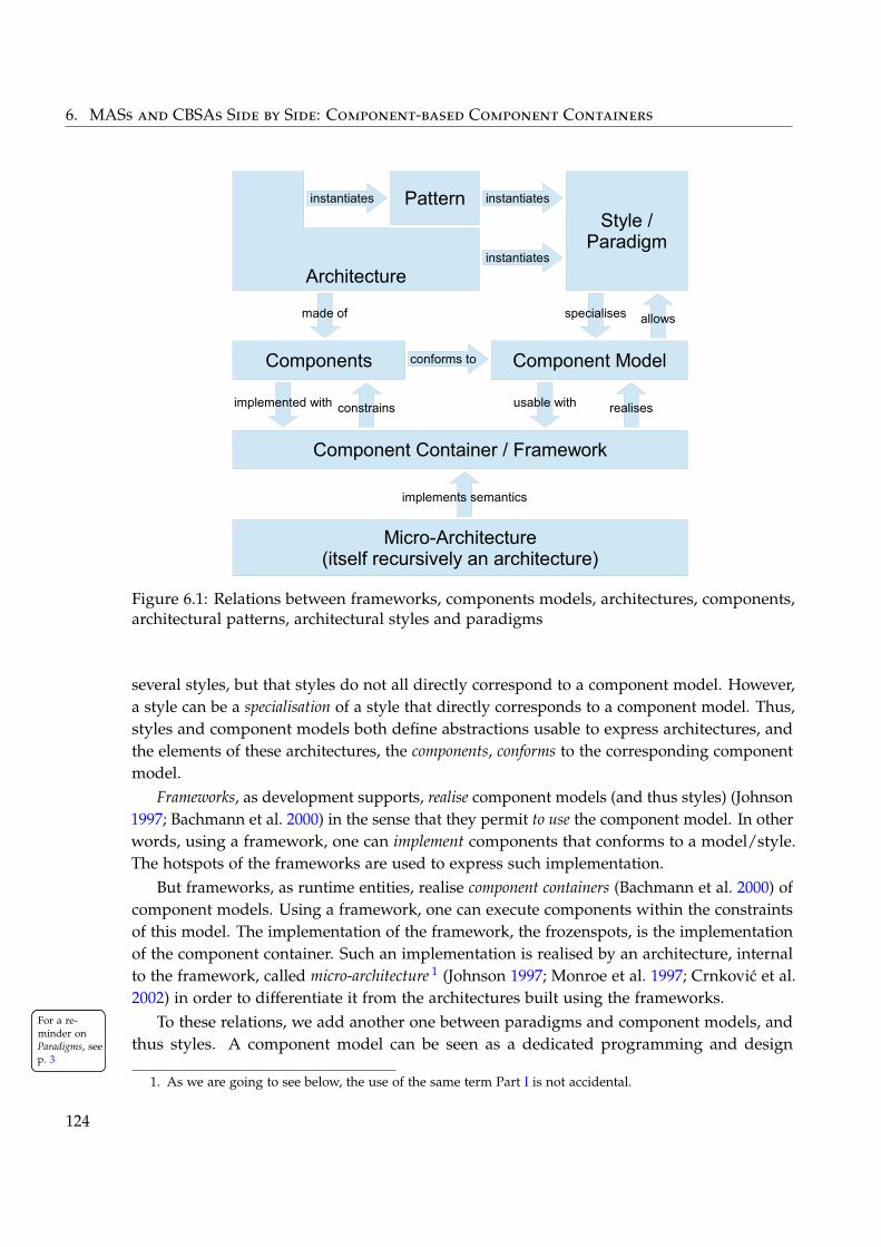
6. MASs and CBSAs Side by Side: Component-based Component Containers
Pattern
Components
Style /Paradigm
Component Model
Component Container / Framework
Micro-Architecture(itself recursively an architecture)
allowsspecialises
instantiates
instantiates
conforms to
made of
implemented with usable with
implements semantics
Architecture
instantiates
constrains realises
Figure 6.1: Relations between frameworks, components models, architectures, components,architectural patterns, architectural styles and paradigms
several styles, but that styles do not all directly correspond to a component model. However,a style can be a specialisation of a style that directly corresponds to a component model. Thus,styles and component models both define abstractions usable to express architectures, andthe elements of these architectures, the components, conforms to the corresponding componentmodel.
Frameworks, as development supports, realise component models (and thus styles) (Johnson1997; Bachmann et al. 2000) in the sense that they permit to use the component model. In otherwords, using a framework, one can implement components that conforms to a model/style.The hotspots of the frameworks are used to express such implementation.
But frameworks, as runtime entities, realise component containers (Bachmann et al. 2000) ofcomponent models. Using a framework, one can execute components within the constraintsof this model. The implementation of the framework, the frozenspots, is the implementationof the component container. Such an implementation is realised by an architecture, internalto the framework, called micro-architecture 1 (Johnson 1997; Monroe et al. 1997; Crnkovic et al.2002) in order to differentiate it from the architectures built using the frameworks.
To these relations, we add another one between paradigms and component models, andFor a re-minder onParadigms, seep. 3
For a re-minder onParadigms, seep. 3
thus styles. A component model can be seen as a dedicated programming and design
1. As we are going to see below, the use of the same term Part I is not accidental.
124
6.3. Defining and Using Dedicated Component Models and Containers
paradigm, or specialised design language as said above. Like a paradigm, a component modeldefines a coherent set of programming abstractions. The components that conform to thecomponent model are implementable using such a paradigm using the abstractions providedby the hotspots of the framework/container. The container acts as the abstract machine thatexecutes such programs/components.
6.3 Defining and Using Dedicated Component Models andContainers
We now look at what must be done when one wants to define a component model andthe container that allows to use it to implement components. The need for such a thing isdeveloped in the next chapter where we use self-organising MASs as the semantics of diversecomponent models.
We rely on the relations between component-based architectural concepts identified in theprevious section to help the identification of the important elements to define. The reader canrelate to Figure 6.1 for a better understanding of the concepts manipulated here. Again, inthis section we put SpeAD aside.
This section proposes our own understanding of how to:
– Define a component model.
– Define a component container/framework, i.e. define the hotspots to implement compo-nents.
– Use them for programming and executing components that conform to and rely on themodel and container.
As we said in the introduction, this is done in a quite abstract way that cannot be considereda formal demonstration, but only an informal presentation of our ideas.
A simple example is used to illustrate these different activities. Next chapter shows morecomplex examples that exploit them.
6.3.1 Defining the Component Model
It is first needed to define the dedicated component model and its semantics. There exista lot of works in the field proposing definition for the semantics of component model, wedon’t dare to concurrent them, but we only present what interests us here in order to definecomponent containers next. As a basis for discussion, by semantics, we could mean “theset of component types, their interfaces, and, additionally a specification of the allowablepatterns of interactions among component types” as proposed by Bachmann et al. (2000),but we also mean, inspired by the definition of architectural styles, the constraints that thecomponents must conform to. But what interests us the most here is the semantics of thecomposition: what are the means of expressing how components are composed, followingwhich dynamics, etc.
125
6. MASs and CBSAs Side by Side: Component-based Component Containers
For example, a traditional event-based component model could be defined as allowingthat components, executed each in their own process, are defined with provided and requiredports to send and receive events, and are composable in static configurations. This thenmeans that components must only be implemented in terms of their ports, reactions to andsending of events, or in terms of compositions of components.
6.3.2 Defining the Component Container
As we previously highlighted, a good way of realising and implementing a componentmodel is to build a component framework, also called component container. In other wordsthe component framework/container is the development support usable to describe andimplement the components, including the description of how they are composed together.
The idea is to define clear hotspots to represent how to program the components, butalso to potentially “configure” the container itself. These hotspots should be elicited from thecomponent model defined previously.
The general idea is to have what we call component hotspots to describe each type ofcomponents that can be programmed with the container. Indeed, as we said, a componentconforming to a component model must comply to some constraints and are allowed to usesome patterns of interactions. For example, for a traditional ADL there could be two differentcomponent hotspots:
– Both would give the possibility to define the set of provided and required ports and away to identify the component.
– One would give:– The possibility to implement the different provided ports.
– Access to the required ports.– The other would give the possibility to express how components, themselves expressed
with the hotspots, are composed with each other.
On top of that, there can exist container hotspots. Indeed, depending on the context, therecould be specific things to express about the container itself and not the components that liveinside it. For example for a component model that let distributed components communicatetogether transparently, this could contain the information needed for every instances of thecontainer to know each other.
6.3.3 Implementing the Component Container
Then, based on the defined hotspots, the container/framework can be implemented torealise the semantics of the component model. This corresponds to the building of the micro-architecture of the component container, or in other words, implementing the frozenspots.We don’t detail here how to implement containers, but this approach is obviously consistentwith how object-oriented languages can be used to build frameworks, and thus componentframeworks/containers. Section 6.4 shows how this is also actually practicable with theabstraction introduced in SpeAD.
126
6.4. Building Dedicated Component-Based Component Containers
6.3.4 Using the Component Container
Based on that container, one can now realise an application that relies on the definedcomponent model. In particular, it clearly separates the concerns of composition or adaptationprovided by the model from those of the application and its business objectives. Examples ofsuch applications are given in the next chapter.
6.3.5 Going Further
To conclude, all of this is just an introduction to the question of defining and usingdedicated component models, but a lot of things can be investigated in this domain. Inparticular, we think about the links with existing works and in particular DSLs (DomainSpecific Languages), which is a proven solution to make the use of a dedicated language For a defini-
tion of Do-main SpecificLanguage, seep. 4
For a defini-tion of Do-main SpecificLanguage, seep. 4
programmatically practicable (Ghosh 2010). They are an interesting alternative to frameworksfor defining and building component containers.
6.4 Building Dedicated Component-Based Component Containers
Section 6.1 identifies in SpeAD the role of species and ecosystem respectively as containedand containing as well as the fact that it is usable to build component-based frameworks.Section 6.2 examines the relations between architectural concepts to build and reuse software.Section 6.3 shows how one can define and use dedicated component models and containers.We can now get a new way of interpreting the things we can build with SpeAD.
Indeed, the main idea of this section is that by defining species with abstract components,we actually realise the micro-architecture of component containers/frameworks for componentmodels. In particular, the uses, possibly coupled with parts, realises the implementation of theallowable “interaction patterns” for the components that conform to the component model.
In other words we are building dedicated component-based component containers.Several works defend a vision where component models, programming paradigms or
architectural styles are things that can be built in order to be dedicated to a specific need.
(1) Bachmann et al. (2000) say that “what is needed is a technique for constructing com-ponent models from a kit of model fragments known to support particular qualityattributes”.
(2) Van Roy and Haridi (2004) say that programming paradigms are actually a compositionof programming concepts adapted to some needs in term of expressiveness.
(3) Fielding (2000) proposes to define styles as incrementally built by adding constraints inorder to get particular qualities for the architectures that instantiate it.
Our opinion is that the composition of several species into one composite species withthe use relation corresponds to such idea. Indeed, we can see the uses as the fragments of(1), as providing the concepts of (2) or as providing the qualities of (1) and (3). The internalarchitecture of a species is a component of (1), a program of (2) and conforms to a style of (3).The ecosystem of the species is the container of (1) or the abstract machine of (2).
127
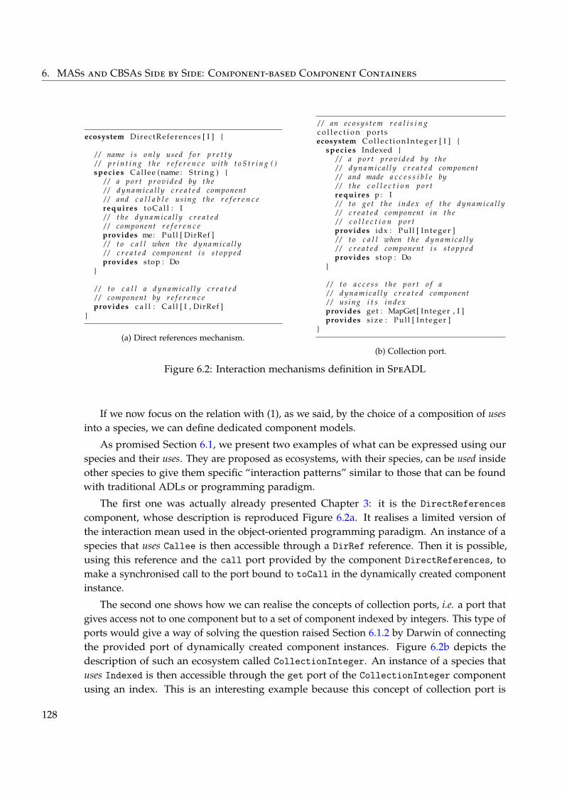
6. MASs and CBSAs Side by Side: Component-based Component Containers
ecosystem Dir ec tR efer ence s [ I ] {
/ / name i s on ly used f o r p r e t t y/ / p r i n t i n g t h e r e f e r e n c e wi th t o S t r i n g ( )species Cal lee (name : S t r i n g ) {
/ / a p o r t p r o v i d e d by t h e/ / d y n a m i c a l l y c r e a t e d component/ / and c a l l a b l e us ing t h e r e f e r e n c erequires t o C a l l : I/ / t h e d y n a m i c a l l y c r e a t e d/ / component r e f e r e n c eprovides me: Pul l [ DirRef ]/ / t o c a l l when t h e d y n a m i c a l l y/ / c r e a t e d component i s s t o p p e dprovides stop : Do
}
/ / t o c a l l a d y n a m i c a l l y c r e a t e d/ / component by r e f e r e n c eprovides c a l l : Ca l l [ I , DirRef ]
}
(a) Direct references mechanism.
/ / an e c o s y s t e m r e a l i s i n gc o l l e c t i o n portsecosystem C o l l e c t i o n I n t e g e r [ I ] {
species Indexed {/ / a p o r t p r o v i d e d by t h e/ / d y n a m i c a l l y c r e a t e d component/ / and made a c c e s s i b l e by/ / t h e c o l l e c t i o n p o r trequires p : I/ / t o g e t t h e i n d e x o f t h e d y n a m i c a l l y/ / c r e a t e d component in t h e/ / c o l l e c t i o n p o r tprovides idx : Pul l [ I n t e g e r ]/ / t o c a l l when t h e d y n a m i c a l l y/ / c r e a t e d component i s s t o p p e dprovides stop : Do
}
/ / t o a c c e s s t h e p o r t o f a/ / d y n a m i c a l l y c r e a t e d component/ / us ing i t s i n d e xprovides get : MapGet [ Integer , I ]provides s i z e : Pul l [ I n t e g e r ]
}
(b) Collection port.
Figure 6.2: Interaction mechanisms definition in SpeADL
If we now focus on the relation with (1), as we said, by the choice of a composition of usesinto a species, we can define dedicated component models.
As promised Section 6.1, we present two examples of what can be expressed using ourspecies and their uses. They are proposed as ecosystems, with their species, can be used insideother species to give them specific “interaction patterns” similar to those that can be foundwith traditional ADLs or programming paradigm.
The first one was actually already presented Chapter 3: it is the DirectReferencescomponent, whose description is reproduced Figure 6.2a. It realises a limited version ofthe interaction mean used in the object-oriented programming paradigm. An instance of aspecies that uses Callee is then accessible through a DirRef reference. Then it is possible,using this reference and the call port provided by the component DirectReferences, tomake a synchronised call to the port bound to toCall in the dynamically created componentinstance.
The second one shows how we can realise the concepts of collection ports, i.e. a port thatgives access not to one component but to a set of component indexed by integers. This type ofports would give a way of solving the question raised Section 6.1.2 by Darwin of connectingthe provided port of dynamically created component instances. Figure 6.2b depicts thedescription of such an ecosystem called CollectionInteger. An instance of a species thatuses Indexed is then accessible through the get port of the CollectionInteger componentusing an index. This is an interesting example because this concept of collection port is
128
6.5. Revisiting MASs Design as a Family of Paradigms
traditionally encoded directly in the component model of ADLs, while here it is definedusing only the abstraction provided by SpeAD.
Obviously these relations and the examples are an over-simplification of the reality, butas with the previous sections, we don’t go into the details of all these relations and how amodel like SpeAD can help build component models. In our opinion, this matter should bestudied more thoroughly, and a lot of things could be said, explored and improved about it.In particular, we think there exist links to identify with existing works that have equivalentobjectives (Hofer and Ostermann 2010; Loiret et al. 2011).
6.5 Revisiting MASs Design as a Family of Paradigms
Obviously, a perfect instantiation of what is said in the previous section, when going backto the main subject of this thesis, are agents and MASs. As we said Chapter 1, MASs area family of architectures: they are conform to a family of architectural styles characterisedby an emphasis on direct peer-to-peer interactions, environment-mediated interactions andreorganisation. One example of a style of this family is the one that was defined in theexample developed Chapter 4 where:
– Agents interact using messages passing and values observation.
– Agents are scheduled together in two synchronised separate steps.
In this vision, then, building a dedicated development support as we advocate is actuallydefining the precise architectural style, or component model, needed for programming theagents. In that case, the agents are the components at runtime, and their behaviours are theimplementation of the components. In another words, designing and implementing a MASis, amongst other things, building a dedicated abstract machine for processing the agents’behaviours, programmed in a programming paradigm dedicated to the MAS design. Forexample, the dedicated programming paradigm of the previous example gives the possibilityto:
– Express the two steps of the behaviour of the agents.
– Access their mailbox.
– Publish observable information.
– Send messages.
– Observe some other agents.
This thus shows an interesting point about MAS approaches: they actually are not onedesign paradigm, but a family of such. Indeed, every type of agents (and thus species)introduces its own set of interaction means and semantics for the execution dynamics of theagents’ behaviours.
In particular, it is worth noticing that the choice of this dedicated programming paradigm For a def-inition ofADELFE, seep. 50
For a def-inition ofADELFE, seep. 50
is strongly linked to the choice of the approach as well as the choices made during macro-leveldesign. Indeed, if we look at systems built with an approach such as ADELFE as in the
129
6. MASs and CBSAs Side by Side: Component-based Component Containers
example above, the choice of the types of agents is very dependent on the domain problemand the dynamics of the agents is mainly enforced by the approach itself. This point of viewon MASs approaches as paradigms should be explored to extract knowledge on the impactsthe choices at macro-level design have on the micro-level design.
More precisely, in terms of programming paradigm, the contribution presented inthe first part of this thesis is actually aimed at defining a dedicated MAS programmingparadigm and its corresponding container. In that context, this better explains why thewords micro-level architectural design is well adapted to denote the design of the architec-ture that provides the abstraction needed to implement the macro-level design.
Finally, this reinterpretation of MASs as architectures defined using dedicated componentcontainers, and the fact that such component containers are themselves defined using SpeADenables us to see a MAS as a component that can take part in a software architecture. Indeed,with SpeAD it is possible to use such containers/frameworks as components, and thus tobuild MASs that are externally considered as components. Such components can then becomposed with traditional components in composites.
6.6 Horizontally Integrating CBSAs, MASs and Other Paradigms
As we showed here, it is possible to integrate the two approaches in an easy and wellorganised way using our abstractions. One can exploit the SpeAD component model todefine traditional component-based architectures where some of the components are actuallythemselves MASs. But the opposite is also possible, as it is actually one of the motivations ofthe first part of this thesis, and the different elements composing a MAS can themselves bedescribed using static and verifiable component-based architectures.
To conclude we now advocate for using design paradigms that are adapted to the needs,and in particular MASs approaches, as they are our primary interest, when dynamicity oradaptivity is required. When it is necessary to build static architectures whose reliabilityshould be formally verified, component-oriented architectures described and implementedwith traditional ADLs should be used. When it is necessary to build very dynamic, emergent,adaptive architectures whose reliability can be validated by experimentation, MASs shouldbe used.
As we illustrated it, other kinds of dedicated component models and containers than thosefor MASs can be built using this approach. And thus, different component containers can liveside to side and be composed using the abstractions provided by SpeAD. We characterise thatas an horizontal integration between different components, including MASs, each possiblywith their own dedicated component model.
However, it obviously looks like this vision of dedicated component-based componentmodels and container is aimed at building component models different from what is tradition-ally done. For example, building something usable to define configurations of components asin ADLs would be using a sledge-hammer to crack a nut. Within such a context, it would
130
6.6. Horizontally Integrating CBSAs, MASs and Other Paradigms
be even more difficult then to tackle adaptivity and complex behaviours of dynamicity incomponent-based architectures.
This is why we don’t advocate for adapting architectures by extending existing andtraditional ways of defining compositions of components. As we just said, one should usedesign paradigms adapted to their problems. But, the horizontal integration that we proposehere keeps clear and hermetic walls between component-based architectures and MASs. Thenext chapter thus proposes to study how both approaches can be integrated vertically andhaving software components self-organising like agents in a MAS. In particular, it presentstwo experiments introducing dedicated component models and containers whose semanticsis inspired by MASs approaches.
Summary of the Contributions⊕We position the contribution of Part I with respect to related works in the softwarearchitecture field.⊕We propose an integrated understanding of the different concepts used in the CBSA(Component-Based Software Architecture) field.⊕We propose a way to define and use dedicated component models and containers.⊕We show how the SpeAD component model can be used to build dedicated component-based component containers.⊕We show how MASs fit in this vision and how MASs as design approaches can beconsidered a family of design paradigms.⊕We show why the SpeAD component model well adapted for horizontal integration ofMASs and CBSAs.
131

CHAPTER 7From Self-Composing Components to
Self-Designing Software Architectures
In the previous part of this thesis, we focused our interest on the development of MASs,which resulted, among other things, into the definition of a novel component model namedSpeAD. We studied this model in the previous chapter, which directed our interest towardsthe realisation of dedicated component containers.
In the present chapter, we completely put aside the concern of micro-level MAS devel-opment and the SpeAD model. Instead, we now focus on the use of MASs as a mean toultimately build self-designing software architectures.
We present here experiments of self-adaptive Component-Based Software Architectures(CBSAs) with various degrees of adaptivity. This brings us to conclude on the interest ofgeneralising such approaches for software architectures, and not limited to CBSAs.
In opposition to the previous chapter, our concern here is clearly to vertically integrateCBSAs approaches with MASs ones. In other words, we want to use MASs as a support forconnecting components to each other, but also to organise their composition in a way adaptedto functional or non-functional objectives. To do so, we exploit the idea that agents can act ascontainers for components at runtime. The important point here is that our objective is not toreplace components with agents, which would result on applying MAS approaches as theyare normally applied, but rather to see how the principles and abstractions used in MASscan support the construction of CBSAs and maintain them in activity with respect to somerequirements.
Such an idea has already been proposed in the past and declined in different ways. Whatmainly differentiate what we propose here from other works are the following points:
– We exploit agents as part of a MASs in the sense that the emerging collective intelligenceis the engine of the self-adaptation of the system. In particular, as we are going to see,this has the advantages of having adaptive systems that can handle underspecifiedcompositions.
133
7. From Self-Composing Components to Self-Designing Software Architectures
– We integrate our solutions with the idea of building dedicated component models andcontainers:
– In terms of design and implementation, it eases the understanding and the identifi-cation of clear points of variability of the solutions. This ensures that the solutionsare actually applicable in practice.
– In term of runtime architecture, agents really encapsulate the components andmediate their interactions. The process of adaptation is not only conceptual but isintegrated with the executed system.
– We identify what features our solutions provide and how they relate to functional andnon-functional requirements.
The chapter is organised as follow. First we present the different arguments that justify theuse of the MAS technology to adapt software architectures and systems. Based on that, wepresent how agents and MASs can be used in this context. Then, we detail two experimentsthat each instantiates different aspects of this vision.
The first was developed in collaboration with the AgentWise research team. It proposes toFor a pre-sentation ofAgentWise,see p. xxiii
For a pre-sentation ofAgentWise,see p. xxiii
adapt a composition of web-services using MASs organisational coordination mechanisms. Itshows a simple degree of adaptivity where the focus is put on non-functional requirements.
The second was developed with a Research Master student during an internship wesupervised (Denis 2011). In the context of ubiquitous computing, it proposes to let componentsexisting in a distributed environment opportunistically self-compose to form applicationsthat are not a priori specified. It shows a higher degree of adaptivity where the focus is notonly put on non-functional requirements, but also on functional ones.
We conclude the chapter by extracting from these experiments an analysis of the linksbetween self-adaptivity, emergence, functional and non-functional requirements. This bringsus to generalise the content of this chapter to the design of software architectures in generaland not only limited to CBSAs.
It must be noted that in this chapter, we consider compositions of, on one hand, compo-nents, and on the other hand, services. In this work, they are both examples of CBSAs in thesense that services and components participate in a composition of runtime elements. But ashighlighted by Hock-koon and Oussalah (2011), component-based and service-oriented soft-ware engineering are two different aspects of the design of software architectures. Obviously,this difference has impacts on how elements of each approach can be composed together.More importantly, the motivations that drive such a composition are different in each case.Nevertheless, we think this does not contradict with what is presented in this chapter.
7.1 MASs for Self-Adaptive Software Architectures
7.1.1 Why MAS
As we previously highlighted, as practitioners of MAS approaches, we are particularlyconvinced by the validity and legitimacy of using approaches that provide collective intel-
134
7.1. MASs for Self-Adaptive Software Architectures
ligence. The global idea behind what is presented in this chapter is that instead of relying For a re-minder onCollective in-telligence, re-ductionism andemergence, seep. 10
For a re-minder onCollective in-telligence, re-ductionism andemergence, seep. 10
on traditional and reductionist ways of composing elements to form a software architecture,we should look at more emergent ways of doing so. Such a concern has been expressed inthe software engineering field for systems considered as coalitions (Sommerville et al. 2011).What characterises such systems is that the different elements that compose them were notproduced together as a whole in order to be composed into one given application. We thinkthis shows a kind of underspecification in the sense that it is difficult to know in advance, forexample when building the components, what is going to be the problem answered by theircomposition and how it should be solved efficiently.
Indeed, even though some functional or non-functional specifications are attached tothe components, the services, or any other elements used in a composition, there is stillunderspecified requirements pertaining to the composition itself or to the way it should beexecuted. This underspecification is one of the main motivation for the current chapter andthe experiments we detail in it.
But furthermore, simply the problem of having self-adaptive software architecture withrespect to clearly identified requirements has also been highlighted in several works. We don’tdetail them here, but only selected two of those that identify points we consider important:
– The need for self-managed systems without external intervention (Van Roy 2007).
– The need for being able to distribute the “algorithm” that drives the adaptation of thesystem (Sykes, Magee, and Kramer 2011).
Because in MASs the control is decentralised by nature and because they showed theirefficiency for self-adaptivity and self-organisation for solving underspecified problems (DiMarzo Serugendo, Gleizes, and Karageorgos 2011), all these aspects of the problem areparticularly well supported by MASs.
7.1.2 MAS-based Containers
The main idea in this proposition is that since systems are made of compositions ofcomponents, there is thus a need for choosing the right composition depending on thefunctional and non-functional requirements 1. Instead of doing this step completely byhand, we propose to use agents as a mean to assist in their composition, or at least in theiradaptation once it has been done or specified. In this vision, agents acts as the container ofthe components, but the mapping between agents and components does not have to be oneto one. For example, in the following experiments, the runtime components are encapsulatedin agents, but there exist other agents in the system participating in the collective intelligence.
Components can then interact together without taking care of selecting or choosing othercomponents. We thus relate this idea to the building of a component model and containerwhose semantics is realised by a MAS. Indeed, the fact that decentralised coordinationmechanisms are introduced into the components of the system implies that the way to
1. Even though a decomposition normally answers some requirements itself, we consider here already definedcomponents.
135
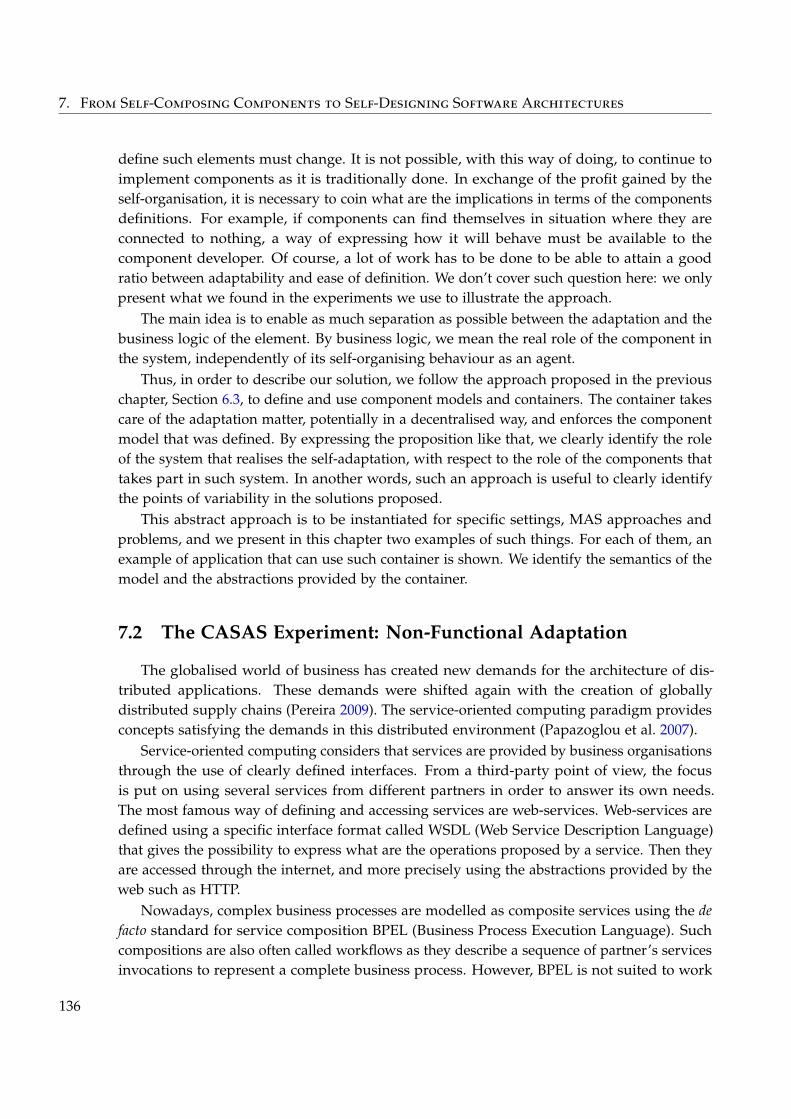
7. From Self-Composing Components to Self-Designing Software Architectures
define such elements must change. It is not possible, with this way of doing, to continue toimplement components as it is traditionally done. In exchange of the profit gained by theself-organisation, it is necessary to coin what are the implications in terms of the componentsdefinitions. For example, if components can find themselves in situation where they areconnected to nothing, a way of expressing how it will behave must be available to thecomponent developer. Of course, a lot of work has to be done to be able to attain a goodratio between adaptability and ease of definition. We don’t cover such question here: we onlypresent what we found in the experiments we use to illustrate the approach.
The main idea is to enable as much separation as possible between the adaptation and thebusiness logic of the element. By business logic, we mean the real role of the component inthe system, independently of its self-organising behaviour as an agent.
Thus, in order to describe our solution, we follow the approach proposed in the previouschapter, Section 6.3, to define and use component models and containers. The container takescare of the adaptation matter, potentially in a decentralised way, and enforces the componentmodel that was defined. By expressing the proposition like that, we clearly identify the roleof the system that realises the self-adaptation, with respect to the role of the components thattakes part in such system. In another words, such an approach is useful to clearly identifythe points of variability in the solutions proposed.
This abstract approach is to be instantiated for specific settings, MAS approaches andproblems, and we present in this chapter two examples of such things. For each of them, anexample of application that can use such container is shown. We identify the semantics of themodel and the abstractions provided by the container.
7.2 The CASAS Experiment: Non-Functional Adaptation
The globalised world of business has created new demands for the architecture of dis-tributed applications. These demands were shifted again with the creation of globallydistributed supply chains (Pereira 2009). The service-oriented computing paradigm providesconcepts satisfying the demands in this distributed environment (Papazoglou et al. 2007).
Service-oriented computing considers that services are provided by business organisationsthrough the use of clearly defined interfaces. From a third-party point of view, the focusis put on using several services from different partners in order to answer its own needs.The most famous way of defining and accessing services are web-services. Web-services aredefined using a specific interface format called WSDL (Web Service Description Language)that gives the possibility to express what are the operations proposed by a service. Then theyare accessed through the internet, and more precisely using the abstractions provided by theweb such as HTTP.
Nowadays, complex business processes are modelled as composite services using the defacto standard for service composition BPEL (Business Process Execution Language). Suchcompositions are also often called workflows as they describe a sequence of partner’s servicesinvocations to represent a complete business process. However, BPEL is not suited to work
136
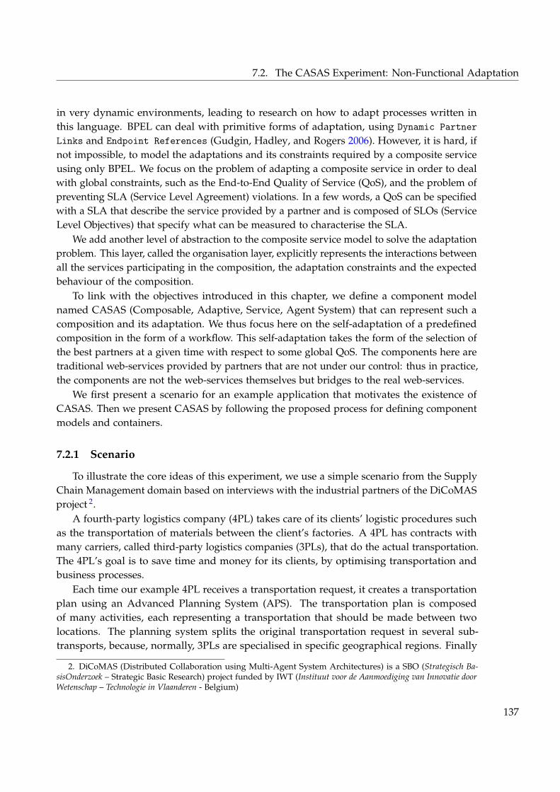
7.2. The CASAS Experiment: Non-Functional Adaptation
in very dynamic environments, leading to research on how to adapt processes written inthis language. BPEL can deal with primitive forms of adaptation, using Dynamic PartnerLinks and Endpoint References (Gudgin, Hadley, and Rogers 2006). However, it is hard, ifnot impossible, to model the adaptations and its constraints required by a composite serviceusing only BPEL. We focus on the problem of adapting a composite service in order to dealwith global constraints, such as the End-to-End Quality of Service (QoS), and the problem ofpreventing SLA (Service Level Agreement) violations. In a few words, a QoS can be specifiedwith a SLA that describe the service provided by a partner and is composed of SLOs (ServiceLevel Objectives) that specify what can be measured to characterise the SLA.
We add another level of abstraction to the composite service model to solve the adaptationproblem. This layer, called the organisation layer, explicitly represents the interactions betweenall the services participating in the composition, the adaptation constraints and the expectedbehaviour of the composition.
To link with the objectives introduced in this chapter, we define a component modelnamed CASAS (Composable, Adaptive, Service, Agent System) that can represent such acomposition and its adaptation. We thus focus here on the self-adaptation of a predefinedcomposition in the form of a workflow. This self-adaptation takes the form of the selection ofthe best partners at a given time with respect to some global QoS. The components here aretraditional web-services provided by partners that are not under our control: thus in practice,the components are not the web-services themselves but bridges to the real web-services.
We first present a scenario for an example application that motivates the existence ofCASAS. Then we present CASAS by following the proposed process for defining componentmodels and containers.
7.2.1 Scenario
To illustrate the core ideas of this experiment, we use a simple scenario from the SupplyChain Management domain based on interviews with the industrial partners of the DiCoMASproject 2.
A fourth-party logistics company (4PL) takes care of its clients’ logistic procedures suchas the transportation of materials between the client’s factories. A 4PL has contracts withmany carriers, called third-party logistics companies (3PLs), that do the actual transportation.The 4PL’s goal is to save time and money for its clients, by optimising transportation andbusiness processes.
Each time our example 4PL receives a transportation request, it creates a transportationplan using an Advanced Planning System (APS). The transportation plan is composedof many activities, each representing a transportation that should be made between twolocations. The planning system splits the original transportation request in several sub-transports, because, normally, 3PLs are specialised in specific geographical regions. Finally
2. DiCoMAS (Distributed Collaboration using Multi-Agent System Architectures) is a SBO (Strategisch Ba-sisOnderzoek – Strategic Basic Research) project funded by IWT (Instituut voor de Aanmoediging van Innovatie doorWetenschap – Technologie in Vlaanderen - Belgium)
137
7. From Self-Composing Components to Self-Designing Software Architectures
<<WSDL>>Composite Service
Start
Invoke
<<BPEL>>4PL
<<WSDL>>3PL-TransportPortType
Carrier 3
Invokes operation
Implements WSDL
Invoke
...
<<WSDL>>3PL-TransportPortType
Carrier 0
Carrier 2
Carrier 1
KEY
...
<<BPEL>>
<<WSDL>>
Carrier X
WSDL InterfaceBPEL Process
Carrier X web-service
... BPEL activity
Figure 7.1: Transportation plan deployed in a BPEL engine
the transportation plan is written as a BPEL process and, after a first selection of 3PLs,deployed in a BPEL engine.
To execute this process, the 4PL’s BPEL engine invokes the selected 3PL’s web-services,informing them about the constraints, such as time constraints, monitoring constraints, etc.
How can we meet the quality requirements of executing a BPEL process within a specifictime frame, even in the presence of partner failures, is the problem that we want to solve.
This problem is illustrated by our example 4PL, that needs to do the transportation withina limited time period, as specified in the plan, but sometimes a partner that previouslycommitted to do a transportation has problems and is not able to execute its part in the plan.For example, a small carrier, that has just one truck, is assigned a sub-transportation, but,suddenly, has a broken truck that needs to be repaired. In this situation, the 4PL needs tofind another carrier capable of doing the transportation for that specific sub-transportation,preferably within the same quality constraints.
Figure 7.1 depicts a simplified transportation plan. The transportation plan is deployedon a BPEL engine and is seen as an internal service within the 4PL, simply called CompositeService here. Each Invoke activity in the transportation plan is executed by an externalservice, through the 3pl-TransportPortType interface, which is implemented by partnercompanies web-services. Each 3PL must comply to the specified QoS, in this case the time todo the transportation.
138
7.2. The CASAS Experiment: Non-Functional Adaptation4 · The MACODO Middleware for Context-Driven Dynamic Agent Organizations
Fig. 2. MACODO organization model.
Traffic jams can span the viewing range of multiple cameras and can dynamically growand dissolve. By default each camera monitors the traffic state within its viewing rangewhich makes up its context. When a traffic jam occurs, the camera has to collaborate withother cameras detecting the same traffic jam. Because there is no central point of control,cameras have to aggregate the data monitored by each of the cameras to determine theposition of the traffic jam on the basis of the head and tail of it. One of the cameras willbe responsible to distribute the aggregated data of the traffic jam to the interested clients.Cameras will enter or leave the collaboration whenever the traffic jam enters or leaves theirviewing range.
2.2 Overview of the MACODO Organization Model
In this section we explain the basic abstractions MACODO offers to the application devel-oper to describe dynamic organizations. We use a graphical notation and give an informaldescription of the abstractions. [Weyns et al. 2009] gives a detailed formal specification ofthe organization model.
Figure 2 shows an overview of the basic abstractions of the MACODO organizationmodel. We explain the abstractions using the scenario shown in figure 3.
Context. Context represents information in the environment of an agent that is relevantfor the organizations in which the agent participates. In the scenario, context includesthe actual traffic state in the viewing range of the camera and the names of the agents onneighboring cameras. The traffic state has three possible values: free flow, bound flow, andcongestion. In a free flow state, vehicles can drive at the maximum allowed speed. In abound flow state this speed is limited. Finally, in a congested state, vehicles are standingACM Journal Name, Vol. V, No. N, November 2009.
Figure 7.2: Domain Model of the Macodo Context-Driven Organisational Model (Weyns,Haesevoets, and Helleboogh 2010)
We now present the organisational concepts used in our solution and the mapping betweenthese concepts and those of the problem. It then serves as a basis to present the CASAScomponent model, its semantics and the constraints it introduces on the components.
7.2.2 The Macodo Organisation Model
The MASs research community has a body of knowledge on Organisational Models. Inthis community, there are two distinct visions regarding these models:
– Organisation being a first class entity, with its properties, states, laws (Weyns, Hae-sevoets, and Helleboogh 2010)
– Organisation mainly as a process, composed by a set of steps to be taken by differentactors (Dignum 2009b)
MASs Organisational Models cope with collaboration between autonomous entities, calledagents, working and interacting together, cooperatively or not, to achieve an organisation goal(DeLoach 2009). In our work we rely on the Macodo (Middleware Architecture for COntext-driven Dynamic agent Organizations) Organisation Model, which defines the organisation asa first class entity with its own dynamics and separated from the participating agents.
The Macodo Organisation Model copes with context-driven dynamic organisations. Withit we can model complex collaborations between different entities, the agents, and specifythe rules that will trigger actions to adapt these collaborations (Weyns, Haesevoets, andHelleboogh 2010).
139
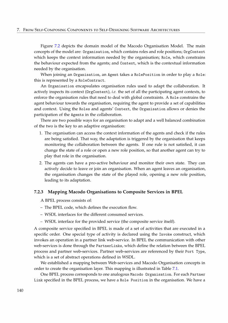
7. From Self-Composing Components to Self-Designing Software Architectures
Figure 7.2 depicts the domain model of the Macodo Organisation Model. The mainconcepts of the model are: Organisation, which contains roles and role positions; OrgContextwhich keeps the context information needed by the organisation; Role, which constrainsthe behaviour expected from the agents; and Context, which is the contextual informationneeded by the organisation.
When joining an Organisation, an Agent takes a RolePosition in order to play a Role:this is represented by a RoleContract.
An Organisation encapsulates organisation rules used to adapt the collaboration. Itactively inspects its context (OrgContext), i.e. the set of all the participating agent contexts, toenforce the organisation rules that need to deal with global constraints. A Role constrains theagent behaviour towards the organisation, requiring the agent to provide a set of capabilitiesand context. Using the Roles and agents’ Context, the Organisation allows or denies theparticipation of the Agents in the collaboration.
There are two possible ways for an organisation to adapt and a well balanced combinationof the two is the key to an adaptive organisation:
1. The organisation can access the context information of the agents and check if the rulesare being satisfied. That way, the adaptation is triggered by the organisation that keepsmonitoring the collaboration between the agents. If one rule is not satisfied, it canchange the state of a role or open a new role position, so that another agent can try toplay that role in the organisation.
2. The agents can have a pro-active behaviour and monitor their own state. They canactively decide to leave or join an organisation. When an agent leaves an organisation,the organisation changes the state of the played role, opening a new role position,leading to its adaptation.
7.2.3 Mapping Macodo Organisations to Composite Services in BPEL
A BPEL process consists of:
– The BPEL code, which defines the execution flow.
– WSDL interfaces for the different consumed services.
– WSDL interface for the provided service (the composite service itself).
A composite service specified in BPEL is made of a set of activities that are executed in aspecific order. One special type of activity is declared using the Invoke construct, whichinvokes an operation in a partner link web-service. In BPEL the communication with otherweb-services is done through the PartnerLinks, which define the relation between the BPELprocess and partner web-services. Partner web-services are referenced by their Port Type,which is a set of abstract operations defined in WSDL.
We established a mapping between Web-services and Macodo Organisation concepts inorder to create the organisation layer. This mapping is illustrated in Table 7.1.
One BPEL process corresponds to one analogous Macodo Organisation. For each PartnerLink specified in the BPEL process, we have a Role Position in the organisation. We have a
140
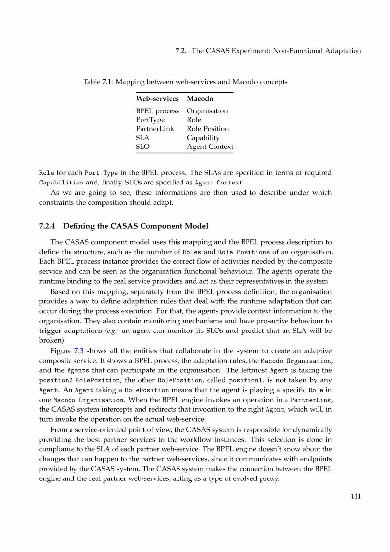
7.2. The CASAS Experiment: Non-Functional Adaptation
Table 7.1: Mapping between web-services and Macodo concepts
Web-services Macodo
BPEL process OrganisationPortType RolePartnerLink Role PositionSLA CapabilitySLO Agent Context
Role for each Port Type in the BPEL process. The SLAs are specified in terms of requiredCapabilities and, finally, SLOs are specified as Agent Context.
As we are going to see, these informations are then used to describe under whichconstraints the composition should adapt.
7.2.4 Defining the CASAS Component Model
The CASAS component model uses this mapping and the BPEL process description todefine the structure, such as the number of Roles and Role Positions of an organisation.Each BPEL process instance provides the correct flow of activities needed by the compositeservice and can be seen as the organisation functional behaviour. The agents operate theruntime binding to the real service providers and act as their representatives in the system.
Based on this mapping, separately from the BPEL process definition, the organisationprovides a way to define adaptation rules that deal with the runtime adaptation that canoccur during the process execution. For that, the agents provide context information to theorganisation. They also contain monitoring mechanisms and have pro-active behaviour totrigger adaptations (e.g. an agent can monitor its SLOs and predict that an SLA will bebroken).
Figure 7.3 shows all the entities that collaborate in the system to create an adaptivecomposite service. It shows a BPEL process, the adaptation rules, the Macodo Organisation,and the Agents that can participate in the organisation. The leftmost Agent is taking theposition2 RolePosition, the other RolePosition, called position1, is not taken by anyAgent. An Agent taking a RolePosition means that the agent is playing a specific Role inone Macodo Organisation. When the BPEL engine invokes an operation in a PartnerLink,the CASAS system intercepts and redirects that invocation to the right Agent, which will, inturn invoke the operation on the actual web-service.
From a service-oriented point of view, the CASAS system is responsible for dynamicallyproviding the best partner services to the workflow instances. This selection is done incompliance to the SLA of each partner web-service. The BPEL engine doesn’t know about thechanges that can happen to the partner web-services, since it communicates with endpointsprovided by the CASAS system. The CASAS system makes the connection between the BPELengine and the real partner web-services, acting as a type of evolved proxy.
141
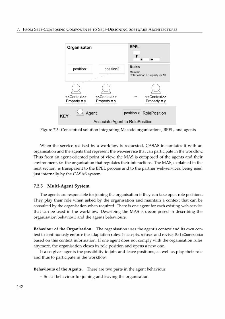
7. From Self-Composing Components to Self-Designing Software Architectures
Organisaton
position1 position2
BPEL
RulesMaintain RolePosition1.Property <= 10
<<Context>>Property = y
...
Agent
Associate Agent to RolePositionKEY
<<Context>>Property = y
<<Context>>Property = y
position x RolePosition
Figure 7.3: Conceptual solution integrating Macodo organisations, BPEL, and agents
When the service realised by a workflow is requested, CASAS instantiates it with anorganisation and the agents that represent the web-service that can participate in the workflow.Thus from an agent-oriented point of view, the MAS is composed of the agents and theirenvironment, i.e. the organisation that regulates their interactions. The MAS, explained in thenext section, is transparent to the BPEL process and to the partner web-services, being usedjust internally by the CASAS system.
7.2.5 Multi-Agent System
The agents are responsible for joining the organisation if they can take open role positions.They play their role when asked by the organisation and maintain a context that can beconsulted by the organisation when required. There is one agent for each existing web-servicethat can be used in the workflow. Describing the MAS is decomposed in describing theorganisation behaviour and the agents behaviours.
Behaviour of the Organisation. The organisation uses the agent’s context and its own con-text to continuously enforce the adaptation rules. It accepts, refuses and revises RoleContractsbased on this context information. If one agent does not comply with the organisation rulesanymore, the organisation closes its role position and opens a new one.
It also gives agents the possibility to join and leave positions, as well as play their roleand thus to participate in the workflow.
Behaviours of the Agents. There are two parts in the agent behaviour:
– Social behaviour for joining and leaving the organisation
142
7.2. The CASAS Experiment: Non-Functional Adaptation
– Monitoring behaviour for managing the context
An agent that receives an event for an open position will try to start a contract if he hasthe capability of playing this role, i.e. he has a matching PortType and the required SLA. Ifthe agent decides to take a role position already taken, if the organisation refuses to give theposition to him, or if the position is closed while playing it, then the agent waits for new openpositions.
The monitoring behaviour is strongly dependent to the type of context required by theorganisation.
7.2.6 Defining the CASAS Component Container
Thus, from the previous sections, we can extract the definition of the different types ofhotspots of our component container. There exists two types of components in this componentmodel: organisation and agent. There is no container hotspots.
Organisation Hotspot. For a given organisation, i.e. a given workflow, it is needed to give:
– The provided interface definition in WSDL.
– The functional behaviour for the organisation: the workflow definition in BPEL.
– The adaptation rules that have to be enforced. For example they can take the formof functions per role position responsible for checking that the QoS indicators of theagents (its context) satisfies the defined SLA for the partner (a threshold). Or could bemore complex as accepted by the Macodo system.
Agent Hotspot. This hotspot is very simple as most of the adaptation is done at theorganisation level. Moreover, the agents mostly play the roles of bridge towards the realservices.
What should be provided for a service is:
– The provided interface definition in WSDL.
– A reference to the web-service they represent.
– An implementation for extracting the context information.
7.2.7 Implementation of the CASAS Component Container
We don’t detail the implementation of the CASAS component container, but details canbe found in Cruz Torres et al. (2010a).
The prototype was written in Java, according to the described architecture. To handlethe service-oriented concerns, CASAS rests on the Apache ServiceMix ESB (EnterpriseService Bus). In particular, this ESB provides the Apache Ode BPEL engine to executethe workflows and the Apache CXF component to access external web services. The ESBprovides mechanisms that can be used by CASAS to intercept messages exchanged in theESB and redirect them to the correct recipients.
Thus, the system is usable directly with real web-services and workflows.
143
7. From Self-Composing Components to Self-Designing Software Architectures
7.2.8 Using the CASAS Component Container
If we instantiate the proposed container with the scenario presented earlier, this gives usthe following. The delivery time of the 3PLs are the context of our agents. The threshold thatshouldn’t be exceeded is determined by the APS for each role position.
The BPEL workflow and WSDL interfaces presented Figure 7.1 are provided with theorganisation hotspot. The adaptation rules are expressed per role position as not exceedingthe threshold.
Dynamically, for each web-service that can play in the workflow, the creation of an agentis parametrised by its interface and an implementation for computing the context informationusing the operations of the interfaces.
Thus, when web-services goes online or offline, their corresponding agents comes in or outof the system. They try to join the organisation and depending on their context informationthey are accepted or not.
7.2.9 Discussion and Possible Evolutions
As we can see, the current state of the proposition is very primitive and doesn’t show somuch intelligence. But, as the auditors of the web-service community workshop, where thiswork was presented (Cruz Torres et al. 2010b), told us, what is interesting in that solutionis the abstractions it provides. The community is in need for such high-level abstractions inthe context of business processes where workflows actually represent collaborations betweenseveral business partners. This experiment shows that it is possible to do so.
We see several evolutions that can be applied to this work. First, related to the Macodomodel, the more it is evolved, and the more advanced the adaptation our system providescan be. For example, it would be interesting to specify global constraints for the wholeorganisation, and not only per role position. Furthermore, the Macodo model is capable ofcreating role positions, expressing relations between them and how the the organisation canevolve: in that context, Macodo could be used to model the reorganisation of the sequenceof activities by moving away from the static aspects of workflows as they are currentlyconsidered. Second, in terms of the mapping between organisational concepts and workflowconcepts, we think it could be interesting to have agents not only act as bridges to the web-services, but also as bridge from the web-services participating in the organisation. Finally,interactions directly between agents could also be interesting. The next experiment illustrateparticularly well this last point in a different context.
It must also be noted that this work was continued with a focus on decentralised coordi-nation mechanisms by the AgentWise task force (Cruz Torres and Holvoet 2011a; Cruz Torresand Holvoet 2011b).
144
7.3. The Greg Experiment: Opportunistic Composition
7.3 The Greg Experiment: Opportunistic Composition
Ambient systems are complex systems composed of interacting (potentially mobile)artificial and humans entities. They are distributed, open, decentralised, heterogeneous,dynamic, etc. Ambient intelligence reflects the capacity of the ambient environment toprovide relevant and adequate services to the humans living within. As it was imagined it 20years ago (Weiser 1991), we are now faced with a new computing environment that asks fornew techniques to build, deploy and maintain applications in production.
In this context, mainly because of mobility and openness, we can imagine that systemscould opportunistically self-construct only because communicating devices are present si-multaneously in the same space. New applications (or software systems) can emerge simplybecause the entities that compose them are in interaction at a given time. For example, amultimedia application such as “watching and controlling a movie” can result from thecomposition between a remote control, a media box, a display device and an audio device.The sole presence of these hardware devices, at a given time and in a given space, shouldallow a system to self-construct without any human intervention. We can thus imagine anapplication that autonomously self-composes, directly from its elements initiative, withouthaving the composition expressed by a designer or a user beforehand, or even without havingthe different components made on purpose for such a composition.
The objective of this work is to explore such question of autonomous self-compositionand to evaluate its feasibility.
As we imagine it, self-composition (at the initiative of the components themselves) raisesoriginal questions compared with more traditional design and programming approaches andtheir context:
– There is no client that express a need nor any design that tries to answer them. Thereis thus no validation that can be done in its traditional meaning (showing that aproduct answers the initial needs). There is neither any specification of the product,thus no possible verification of the conformity of the product with respect with theserequirements.
– There is no designer that creates the compositions and that controls them.
– There exist human users that themselves are part of the system and that can play a rolein the acceptance of the applications that dynamically appear.
The question that interests us here is relative to the opportunistic composition of applica-tions that can be characterised as emergent in an ambient context. But once created, suchapplication must also be dynamically adapted, controlled and maintained in a functionalstate. In this context, we look at how this can be automated and self-adapted.
As with the previous experiment, we first present scenario that motivates it, then theconcepts manipulated, then we propose a solution that we describe using the process weproposed for building and using component models and containers.
145
7. From Self-Composing Components to Self-Designing Software Architectures
7.3.1 Motivating Scenario
This scenario takes place in the context of multimedia ambient application. We imaginedthe following.
(1) David is in his living room and his objective is to watch a HD video on his TV bychoosing one of the movies available on the disk of its internet media box. His TV is onstandby and his hi-fi system is off. He starts the interface to access multimedia contentfrom his smartphone. The system finds two mediacenter (one from his internet boxand one included in its TV) and proposes to David to make a choice. David choosethe mediacenter of its internet box. A browser appears on its screen. He selects thevideo he wants to watch and validates his choice. The video appears on the TV and thesound comes out from the TV integrated speakers. Since he wants to profit from thebetter quality of his hi-fi system that provides 5.1 surround sound, he turns it on andthe sound switches to the speakers of the hi-fi system.
(2) Later in the evening, David turns off the TV (the movie is automatically paused) andmoves to his room because he wants to finish the movie in his bed. He turns on hiscomputer and use his smartphone to start the movie again. The sound comes out fromthe computer speakers. He turns on his headphones and puts them on. The soundswitches to them.
(3) It is 10pm and someone tries to call him. Because David has his headphones on, and heis watching his screen, the phone does not ring but a feedback is sent to the tv. Becauseof that, the movie is put on pause and a visual feedback is shown on screen.
The first part (1) of this scenario should validate that our solution is able to createapplications, that it can resolve problems such as the choice between several boxes, and thatit can propose always the best composition with respect to the user needs (5.1 sound betterthan tv speakers).
The second part (2) should validate the dynamic of the composition (moving betweenplaces, new devices appearing) after it has been created.
The last part (3) should validate that the system can handle conflicts between resources(feedback of the phone versus movie already playing on it).
It is important to notice that the applications that are built during this scenario are nota priori specified. The user only expresses his needs through the use of devices and thecomponents self-compose until they form a working composition.
Figure 7.4 shows an example of a composition that should be self-built by the systemaccording to this scenario. There is several components composed together in a givenconfiguration and thus forming an application. We now present the domain model and theway such components are structured.
7.3.2 Modelling the Problem Domain
In an ambient environment, we can find devices such as a TV set, a media box, etc.Resources are physical entities directly linked to a device, for example the screen of a
146
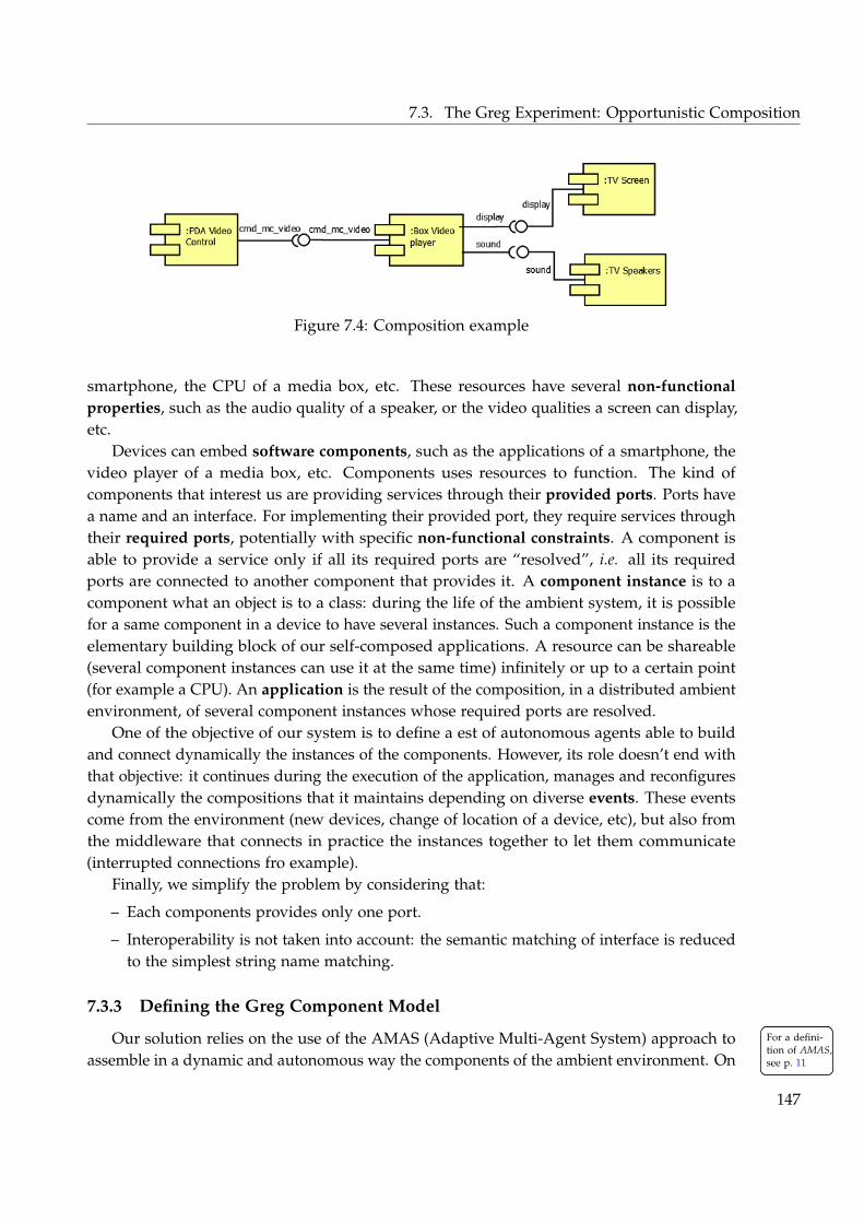
7.3. The Greg Experiment: Opportunistic Composition
Figure 7.4: Composition example
smartphone, the CPU of a media box, etc. These resources have several non-functionalproperties, such as the audio quality of a speaker, or the video qualities a screen can display,etc.
Devices can embed software components, such as the applications of a smartphone, thevideo player of a media box, etc. Components uses resources to function. The kind ofcomponents that interest us are providing services through their provided ports. Ports havea name and an interface. For implementing their provided port, they require services throughtheir required ports, potentially with specific non-functional constraints. A component isable to provide a service only if all its required ports are “resolved”, i.e. all its requiredports are connected to another component that provides it. A component instance is to acomponent what an object is to a class: during the life of the ambient system, it is possiblefor a same component in a device to have several instances. Such a component instance is theelementary building block of our self-composed applications. A resource can be shareable(several component instances can use it at the same time) infinitely or up to a certain point(for example a CPU). An application is the result of the composition, in a distributed ambientenvironment, of several component instances whose required ports are resolved.
One of the objective of our system is to define a est of autonomous agents able to buildand connect dynamically the instances of the components. However, its role doesn’t end withthat objective: it continues during the execution of the application, manages and reconfiguresdynamically the compositions that it maintains depending on diverse events. These eventscome from the environment (new devices, change of location of a device, etc), but also fromthe middleware that connects in practice the instances together to let them communicate(interrupted connections fro example).
Finally, we simplify the problem by considering that:
– Each components provides only one port.
– Interoperability is not taken into account: the semantic matching of interface is reducedto the simplest string name matching.
7.3.3 Defining the Greg Component Model
Our solution relies on the use of the AMAS (Adaptive Multi-Agent System) approach to For a defini-tion of AMAS,see p. 11
For a defini-tion of AMAS,see p. 11assemble in a dynamic and autonomous way the components of the ambient environment. On
147
7. From Self-Composing Components to Self-Designing Software Architectures
top of the fact that such systems seems a priori adequate to tackle such question, as presentedin the introduction of the chapter, we think that in a general way, AMAS are particularlyadapted to the development and the design of application whose specification is not or notcompletely known.
As we presented Chapter 1, in the AMAS approach, the engine of adaptation is thecooperative behaviours of the agents. This behaviour is elicited by identifying NCSs (Non-Cooperative Situations) and by exploiting the concept of criticality.
Cooperative agents have a nominal and a cooperative behaviour. In our solution, thenominal behaviour of the agents is the business concerns of the components they encapsulate.For example, the nominal behaviour of an agent containing a media player component is toactually play the video. In order to apply their nominal behaviour, the agents must be in astate that makes it possible. Obviously if a media player has nowhere to send video, it cannotoperate properly. This is where the cooperative behaviour is used. The cooperative behaviour,expressed in the form of atomic and individual NCS detections and solving, takes care ofputting the system in a usable state. There exist different types of NCSs but we don’t detailthem here.
Of course, depending on the business concern of the encapsulated component, the way tosolve a NCS can vary. In the following, we present the cooperative behaviours of the agents,and when needed we explain how it can vary depending on the business concern of theagents. This later serves as a basis to define the component container and its hotspots.
It must be noted that this solution is perfectible and its main objective is to show thefeasibility of using such a bottom-up approach to self-composition.
7.3.3.1 Types of Agents
In our system, we have two types of agents: class agents and instance agents. The ideais that in each device, there is one class agent responsible for each software component thatcan be instantiated. When needed, by interacting with other agents as we are going to see,such an agent can create instance agent of its components.
These instance agents are responsible of playing their role in a given application, byresolving conflicts and dependencies with other instances in the system. Instances can becompletely, partially or not resolved: it means their required ports are, respectively, all, notall or not connected to another instance.
7.3.3.2 Neighbourhood
Devices are on a network, and thus can “see” each other using traditional broadcastmeans used on local networks, such as the IP protocol. When a device is started in a givenenvironment, then for all the software components in it, their class agent is created and thusare in the physical neighbourhood of other agents in their range. Inversely, if the device isstopped or stops working for any reason, then the class and instance agents disappear andthus disappear from the physical neighbourhood of other agents. If the device goes out ofrange of other devices, the same happens.
148
7.3. The Greg Experiment: Opportunistic Composition
A class agent is interested in a subset of its physical neighbourhood: the requires neigh-bourhood contains class agents that have interfaces it requires. These neighbourhood aremaintained internally by each class agent, while the physical neighbourhood is induced bythe physical network. A class agent also have its instances neighbourhood composed of allthe instance agents it created.
An instance agent has a potential neighbourhood of instance agents that it can potentiallyconnect to. It also knows its class agent.
7.3.3.3 Agents Behaviours
We now detail the different informations managed by the agents, the events that canhappen and what are the agents actions. These “behavioural rules” are induced from theNon-Cooperative Situations that were identified but not detailed here.
In our solution, the questions of constructing the application and adapting it are consideredthe same problem. For example, either at construction or after a composition has been fullyconstructed, an instance that finds itself with one of its port not resolved anymore will handlethe problem in the same way.
Instance Behaviours. An instance agent is responsible of a component instance. Its mainobjective is to find the “best” instance agents to resolve its required services.
Every time an instance is requested to be potentially used by another instance, it isable to compute its capability level with respect to the request. Such a capability level iscomputed from the non-functional properties of the resources used by the instance agent, thenon-functional constraints of the request and from the best capability level of its resolvedrequired ports. Indeed, for each of its required ports, an instance agent maintains its potentialneighbourhood (using various ways that we describe after) and store the capability level ofeach of the instance it can use. For example, a video player trying to play a 5.1 video couldhave a capability of 80% if its required port for streaming sound is not resolved to an instancethat can handle 5.1. And thus, the “best” instance for a given required port is the instancewith the best capability.
On the other hand, an instance agent also have a criticality level. This level representshow critical is an agent in resolving its required ports. It is used to solve conflicts overresources and to drive the reorganisation by having agents leaving their current role inorder to answer more critical requests. The main difficulty here is to find the best way tocompute such a criticality. First, it is partially inherited from other instances that requested itsservice. But this information also varies with the business concerns of the components. Forexample, a request emanating from an instance agent that was created after a user launchedan application can have a criticality that increases until it is not answered, while a requestfrom a component created automatically by the system wouldn’t change.
There is 10 behavioural rules that are roughly decomposed in three different aspects: main-taining the potential neighbourhood, handling connection to other instances and resolvingconflicts over resources.
149
7. From Self-Composing Components to Self-Designing Software Architectures
Maintaining the potential neighbourhood:
1. After it is started, it regularly sends requests for its required ports along with theinterface type and the non-functional constraints.
2. When it receives a request for potentially using its provided port, it answers positivelywith a capability level computed functions of the request.
3. When it receives an answer for one of its required ports or when there is a capabilityupdate, it updates its potential neighbourhood and their capabilities.
4. When its capability changes, it propagates it to the instance using it, which in turn islikely to do so, which can trigger reorganisation somewhere in the system.
Managing connections to other instances:
5. When another instance request to connect to it:
– (1) If it is in a completely resolved state:
– (2) If there is no conflict with another instance on its needed resources, then itaccepts.
– Else, for each resources it needs, if there is a conflict with other instances:
– It asks them to leave the resources with its criticality as information.
– When a positive answer comes back, go to (2).
– Else, for each of the unresolved ports:
– It notifies the “best” instance, along with its criticality level, that it wants toconnect to it.
– When a positive answer come back, go to (1).
6. When there is a new “best” instance agent to connect to and it is already connected:
– The agent notifies the new one, along with its criticality level, that it wants toconnect to it.
– When a positive answer comes back, it notifies its previous “best” that it disconnectsit.
7. When its criticality changes, it propagates it to the agents it is connected to, which inturn are likely to do so, which can trigger reorganisation somewhere in the system.
8. When it receives a disconnection notification for a required ports (from an agent or fromthe middleware), it notifies the instance using it that it is disconnecting its providedport, and it updates its criticality (and thus propagates it).
9. When it receives a disconnection notification for its provided port (from an agent orfrom the middleware), it updates its criticality (and thus propagates it).
Resolving conflicts over resources:
10. When it receives a request to leave a resource and if its criticality is lower than therequester:
150
7.3. The Greg Experiment: Opportunistic Composition
– It leaves the resource.
– It notifies the requester.
– It updates its capability (and thus propagates it).
– It notifies the instance using it that it is disconnecting its provided port.
At different times, the components can have a behaviour that varies depending on theirbusiness concerns. As previously highlighted, to compute their capabilities or to computetheir criticality. But also, it is needed to specify the components behaviours when theyfind themselves in a non working state. Indeed, when a component is executed and theimplementation tries to use the required ports after being called on their provided port,everything is connected. But if there is a failure at one moment, the component must definehow it should be handled in its particular case.
For example, with required ports that get disconnected, a video player would just go intopause, while a remote control would show an error message. Actually, with the way thingsare current handled, in other all the cases, any instance we could think of would terminate.Then when a new composition would be formed, new instances would take the relay.
A more complex and mature solution would most certainly introduces more interestingpoints of variability. For example the computation of the capability could be business-specificand would help drive the composition towards something that better answer the users needs.
Class Behaviours. Class agents are much more simple.After it is started, it regularly broadcasts the existence of its provided port.When it receives a broadcast about the existence of a provided port with the same interface
as one of its required ports, it stores it in its requires neighbourhood.When it receives a request for potentially using its provided port, it creates an instance
and forwards the request to it.Depending on the business concern of the components, the reason for creating instances
are different. For example an instance of a component for a user interface is created when theuser launch the application.
7.3.4 Defining the Greg Component Container
Thus, from the previous sections, we can extract the definition of the different types ofhotspots for our component model.
Since all the dynamics of the model is managed from inside the agents, and thus thecomponents, the container would only have some configurations about the resources of agiven device.
For each of the component, it is needed to provide:
– An implementation for its provided port, that can use the required ports.
– An implementation for computing the criticality (or a part of it) of the component.
– An implementation for the different hooks corresponding to specific actions to executewhen special events happen:
151
7. From Self-Composing Components to Self-Designing Software Architectures
– When getting disconnected for provided port.
– When no instance is found to resolve the required ports (and thus when they aredisconnected).
7.3.5 Implementation of the Greg Component Container
We don’t detail the implementation of the container but information about it can be foundin Denis (2011).
The prototype is actually realised using SpeAD and SpEArAF. A home made simulatorwas built for the networks, the devices and the resources.
7.3.6 Use of the Greg Component Container
The only thing that must be predetermined beforehand and that should be shared by everyimplementation of components conform to the container is the meaning and normalisation ofthe criticality. This is one prerequisite of the AMAS approach. There could be a standard thatdefine its meaning, for example that defines which are the default values for a user requestedaction, for an automatically created component, for an urgency, or things like that.
In the scenario, there are two types of ports: streams such as video, audio, etc, andcall-return. The latter are the ports prefixed by cmd Figure 7.4.
We now show how a component for a video player is implemented using the componentcontainer.
Its provided port can accept commands to control the execution of the video, i.e. play,pause, stop, etc. It has two required ports: one to stream sound and one to stream video. Itsimplementation is a process that streams video and sound when the play signal is sent to itsprovided port, stops streaming when the pause signal is received and terminates when thestop signal is received.
The criticality function is the default one for automatically created components. Theimplementation of what to do when the provided port is disconnected is to terminate. Theimplementation of what to do when required ports are not resolved, is to put the video onpause.
It is a cooperative behaviour towards the users but also towards other components of thesystem in the sense that:
– If it is not controlled by anything, then it does not have any reason to exist.
– If it is still controlled but can’t stream, then it should not play the video, which wouldbe against user’s desire.
7.3.7 Discussion and Possible Evolutions
What this system proposes is enough to demonstrate that it is possible to have componentsthat self-compose in a physical and conceptual distributed context. On the other hand, wehave a lot of ideas on how to improve it.
152
7.4. Discussion: MASs for CBSAs
First, concerning the ways to express users needs in terms of components behaviours, itseems relevant to consider that a component providing a port is as much as important thana component requiring a port. For example, a user putting headphones on means a newprovided port is announced in the system, and thus, the user need is that this provided portshould be connected.
Then, even though components should be encapsulated by agents, it would much moreinteresting to have agents encapsulating each of their ports to introduce even more local andemergent behaviour. For example, this would be useful for expressing dependencies betweenports that should be connected together to a same device.
7.4 Discussion: MASs for CBSAs
We presented two MASs-based component containers. In order to conclude this chapterwe comment them and discuss their differences. This gives us the opportunity to draw someconclusions on the links between functional and non-functional requirements, self-adaptation,emergence and the aforementioned underspecification. Furthermore, we also conclude on theadvantages of explicitly defining the proposed solutions as component models and containers.
7.4.1 Adaptation and Emergence
In the CASAS experiment, the functionality of the composition is completely specifiedbeforehand using a workflow description. The system provides the “intelligence” that choosesthe right partners. Indeed, the organisation, by the definition of adaptation rules, enforces theglobal constraints of the composition and drives the reorganisation. But furthermore, as weexplained, the agents can, by themselves, decide to leave the organisation, when individualconstraints are not respected. Thus, in this system, what drives the reorganisation and thusthe self-adaptation of the system is clearly the non-functional requirements expressed by theService Level Agreements and Service Level Objectives.
In the Greg experiment, the functionality of the composition is not specified at all, butthis doesn’t mean the functionality emerges from nothing. Indeed, because the elements ofthe composition are functional components, the relation between the self-built applicationfunctionality and the functionality of the elements is purely reductionist. However, thecomposition process itself can be said to be emergent: indeed, what emerges from theinteraction of the agents is the selection of the components, and in which configuration. Andthen some conflicts at a point of the composition is propagated to another place and cantrigger reorganisation. Thus, the functional requirements drive the self-composition of thecomponents and the non-functional requirements guide it towards the most adapted one. Theways this can be controlled is through the notion of cooperation, expressed by the criticality,that implies some specific choices by the agents at some points, and the capabilities thatrepresent the level of satisfaction of the functional requirement. Thus, to conclude, in thissystem, what drives the reorganisation is:
153
7. From Self-Composing Components to Self-Designing Software Architectures
– The functional requirements expressed by the required ports of the components andtheir interfaces.
– The non-functional requirements expressed by the capabilities of the components andtheir non-functional constraints.
– The user needs that are some kind of functional requirements not formally specified,expressed in a cooperative way by the notion of criticality.
The two first points are what, in our opinion, enables the self-composition of componentsin a completely decentralised way. That last point is what, in our opinion, introduces anadaptation to the underspecification of the system highlighted in the beginning of this chapter.
In the end, the two systems are not so far from each other in their objective becausethey both optimise the selection of the components to compose. To better understandthe links between the two, we can use the differentiation coined by Bouziane, Pérez, andPriol (2008) between workflows as defining a temporal relation between the elements of thecomposition and component-based compositions as defining a spatial relation between theelements of the composition. Indeed, in the first system, the functionality is described usinga temporal relation between the elements, while in the second system, their composition isspatial. Obviously, the first one seems to be much more complex to handle in terms of self-composition and reorganisation of the sequence because of the complexity of the semanticsof such composition. But what this also highlights is that actually in the second case, thistemporality is hidden in the component and expressed through the way a component isimplemented and uses its required ports. This just opens the discussion on the matter, andwe think this should be better explored to better understand how we can better adapt thesekinds of software architectures at runtime. Moreover, as highlighted in the introduction of thechapter, this discussion should most certainly also take into account the differences betweencomponent-based and service-based approaches to composition.
7.4.2 Component Models and Containers
Concerning the definition of the component models and containers, these examples showthat when using a semantics for the component models that is very different to what istraditionally done in the software architecture field, there are impacts on the informationneeded to be provided for the implementation of the components. It supports the argumentthat if new methods of composition are used, then it would be vain to keep using alwaysthe same traditional abstractions to define components. In particular this is visible with thesecond solution where the concept of cooperation leaks out at the business level. We thinkthis point is strongly linked to the question of underspecification as it is one of the mainreason we novel different semantics for the component models.
It also shows that by expressing these details about the container hotspots, it clarifies for agiven component model the points of variability and eases its documentation.
But moreover, by using the component container abstraction to realise such system, webuilt systems that integrate together the decision and its actual execution. Indeed, as we said,
154
7.5. Towards Human-Assisted Self-Designing Software Architectures
what emerges from these systems is the choices of the components to use, and the choices ofhow to connect them. The system applies these choices in order for the system to be executedin direct. This is interesting because such an approach makes the bridge between, on onehand, the concepts and the reasons behind the existence of a particular organisation, and, onthe other hand, the elements of this organisation and their actual composition.
7.4.3 Better Adaptation for CBSAs
Finally, we think, as it is highlighted by the methodological precepts of Agent-Based Mod-elling as instantiated by the AMAS approach, that a good definition of the problem domainis what is important for having a good self-adaptive system that answers its requirements inan adequate way. There is thus most certainly more works to do to spot the right abstractionsfor representing components and their dependencies. We think in particular about the workof Desnos et al. (2007) that raises and answers some of these questions by proposing the samekind of compositions than the second experiment, except for the underspecification of theuser needs, but in a totally centralised way.
7.5 Towards Human-Assisted Self-Designing SoftwareArchitectures
To illustrate how MASs could be used to support the self-adaptation of systems, wepresented the idea of building MAS-based containers. This approach is principally based ona runtime adaptation and only for components. On the other hand, in the previous chapter,Section 6.2, we presented how the concepts used in architectures are related to each others.In particular, it highlighted that a given component model allowed a number of architecturalstyles instantiated by architectures and patterns.
In this section, we propose to first give an understanding of the relations between thestate of a CBSA at runtime and the architectural styles and patterns that it instantiates. Then,we generalise that idea to software architectures in general as a mean to support the designof software systems.
7.5.1 Styles and Patterns that Emerge
If the elements of an architecture can self-organise at runtime, then at a given time, theirorganisation is in a particular configuration. Such a configuration is possibly an instantiationof an architectural style or pattern. For example, a set of components could all be using thesame other one: this would instantiate the client-server style.
And thus, the runtime architecture has several qualities that are induced by this configura-tion, or in another words, the runtime architecture answers some non-functional requirements.Inversely, we could imagine that a wanted quality would drive the self-organisation so thatan adapted configuration of components is reached by the self-adaptive architecture.
155
7. From Self-Composing Components to Self-Designing Software Architectures
The main problem with such an idea is that most of the architectural styles that existsconstrains so much the way components are implemented that it becomes difficult, foran already defined component, to be used in different styles. There must still exist someexamples of styles and components for which this approach would work, but this is a questionwe won’t answer here.
More interesting in our opinion, if we generalise this vision to software architecturesbuilding, we think that creating self-designing architectures is more realistically feasible.
7.5.2 Generalisation to Architectural Views
Indeed, nothing prevents this approach to be applied to all the aspects of softwarearchitectures such as the design, the decision making, the application of design choices toactually build the architecture, the matching between the views, the solving of conflicts, etc.The idea would be to have a tool that helps elicit the different views of a software architectureFor a defini-
tion of Archi-tectural Views,see p. 7
For a defini-tion of Archi-tectural Views,see p. 7
by answering feedbacks from the designer as well as from a repository of knowledge eitherdomain-specific or generic.
By using the designer as a way to give feedback to the tool, it becomes much moreeasy to automatise the adaptation of all the structures of the system in a coherent way.Indeed, the tool would then provide the intelligence needed to manage the application of themodifications or to keep the architecture coherent, while the designer would act as the driverof the self-organisation.
From the point of view of the elements of the architectures, i.e. modules or components,they would act as the components of the previously presented experiments. They wouldtry to form coherent structures that answer the expressed functional and non-functionalrequirements. But they would do so from different views at the same time. One of themcould for example be a decomposition view, and the modules could try to find the betterdecomposition with the help of the designer feedbacks. In parallel, we could have layeredview that would enforce the constraints expressed by the designer, or maybe found by thesystem itself. Then, we could have a mapping view between modules and components,components views, etc. This could even go to the point where one of the views is the actualrunning system made of the real instantiated components, encapsulated by agents as in ourprevious examples.
Such a system could be used to assist in the decision making for designing the architecture,but also in the actual application of the changes to the running system. Knowledge aboutknown patterns and styles could also be made available to such a system to better supportthe design.
Approaches for assisting evolution has already been proposed in different works such asLe Goaer et al. (2008) or Garlan et al. (2009). What differentiate our proposition from theseare, on one hand, the links that exist between the runtime and design-time self-organisation,and, on the other hand, the fact that the system would be totally integrated to tackle togetherall the aspects of the software architecture. Such a tool would then gracefully make the bridgebetween design, deployment and maintenance.
156
7.5. Towards Human-Assisted Self-Designing Software Architectures
Summary of the Contributions⊕We highlight the reasons that motivate the use of technologies such as MASs for theadaptation of software architectures.⊕We propose MAS-based component containers to have self-adaptive self-composingComponent-Based Software Architecture.⊕We illustrate that vision with an experiment that adapt a composition of services.⊕We illustrate that vision with an experiment that let components opportunisticallyself-compose in a completely decentralised and distributed way.⊕We present an understanding of the relations between self-adaptation, emergence, func-tional and non-functional requirements, and highlight the role of the underspecificationin a the adaptation of a composition.⊕We present challenges that these experiments raise.⊕We present the idea of a support tool for self-designing architecture that tackles inan integrated way the design of the software architecture up to its its deployment,maintenance and evolution.
157


B A C K
159

CHAPTER 8Conclusions and Perspectives
The initial objective of this Ph.D. was to contribute to the field of MAS development inorder to support the transition between design and implementation. In order to reach suchresults, we uncovered several elements of contributions in the field of MASs and softwarearchitectures.
We propose to present these contributions from four different points of views that eachpertain to a specific field or combination of field. The balance in size between the first partand the second part is not reflected by these four points of view. Indeed, the first part, whichis the biggest of the two, answers the two main motivations of this thesis, that is improvingthe development process followed in MASs as well as its products, the MASs themselves.Then, on the other hand, the second part answers the third motivation, that is understandingthe relations that exists between MASs and software architectures with a focus on CBSAs.This is mainly due to the fact that this part is mostly exploratory and results on set of axis ofresearch that have to be deepened.
To close this thesis, we present some open questions and perspectives of research.
8.1 Contributions of the Thesis
8.1.1 Software Architectures for Multi-Agent Systems
Encouraged by the numerous evidences of the existence of a gap between design andimplementation in MASs development, we thoroughly studied and analysed the variousexisting means of development that exist in the field, both for design and for implementation.This brought us to point up a particular specificity in MASs development: all the requirementsthat are expressed initially when developing a MAS are not all answered by the design, andthus must be answered at implementation. Moreover, the choice of a given approach to MASdevelopment, and there are many, introduces supplementary requirements that also must beanswered at implementation. On top of that, the choices made during the design by the MAS
161
8. Conclusions and Perspectives
designer are themselves new requirements towards the implementation. The combination ofall those requirements makes each development very specific to the problem answered, tothe MAS developer, to the chosen design approach, etc. The main conclusion here is that itis not possible to have a “one-size-fits-all” development support that would support everydevelopment and its specificities. The second conclusion is that every time a MAS design isbeing produced, the requirements that have an important impact on the implementation canbe expressed as the definition of the types of agents of the application being developed. Suchtypes of agents describe what are the interaction means that the agents use, what are theirinternal dynamics, but also more operative constraints that are important for the design andthe implementation. We thus extracted challenges for the design and the implementation ofsuch types of agents in order to better support the implementation of the MAS design itself.
To answer that, we proposed a coherent set of answers that takes its inspiration fromsoftware architectures as a mean to organise the development, and Component-Based SoftwareArchitectures (CBSAs) as a mean to support the development with quality, productivityand maintainability in mind. It takes the form of our own understanding of the generalmethodology of MAS development. This methodology separates the development into twophases. The first one is what we call the macro-level architectural design, focused on applyinga MAS approach to define the system in terms of agents, their behaviours, their interactions,etc. The second one is what we call micro-level architectural design, focused on building anarchitecture adapted to the specific types of agents of the development and providing theabstractions needed to implement the MAS design in a straightforward way.
In order to ease the construction of such a micro-level architecture as well as make reuseand maintenance possible, we proposed next a novel component model, named SpeAD(Species-based Architectural Design), that introduces specific abstractions, namely speciesand ecosystem, that are usable to define and implement the types of agents of a givenapplication and their computational environment. We showed how SpeAD can be usedto model common interaction means as well as more operative ones. We also proposed amethod, named SpEArAF (Species to Engineer Architectures for Agent Frameworks) thatinstantiates the general methodology of MAS development with SpeAD. To illustrate allof that, we presented a real MAS-based application from a research project developed inour research team. We analysed the contribution with respect to the state of the art, to thepreviously identified implementation challenges and to experimental feedbacks from users toconclude on the advantages of using our contribution for MAS development.
8.1.2 Component-Based Software Architectures
From this contribution, we proposed to compare it to existing works from the softwarearchitecture field, and in particular the Component-Based Software Architectures (CBSAs)field. This brought us to draw a set of ideas on the production of development supports forCBSAs without considering MASs at all.
To support the proposed ideas, we presented an integrated understanding of the differentconcepts used in the CBSA field, namely frameworks, components models, component
162
8.1. Contributions of the Thesis
containers, architectural patterns, architectural styles, architectures and components.We first compared our use of the proposed component model with object-oriented frame-
works to conclude that our model could be used to define component-based frameworks.In particular, this idea is used in the first part to provide reusable architectures with partialimplementation for MAS development.
Then, we compared the abstractions we introduced in our model to the dynamic in-stantiation of components as it can be found in works of the field, and then, by relating toseveral works in the literature, we showed how our component model could be used to builddedicated component-based component containers.
These results are of course still in the rough and we thus tried to show for each whichwere the directions to explore.
8.1.3 Multi-Agent Systems and Component-Based Software Architectures Sideby Side
In the light of the previous results, we then re-examined MASs development with respectto CBSAs.
The main conclusion we drew is that, coherently with the conclusions of the state of theart, MASs approaches are not one design paradigm, but a family of such. And linking thatto our component model and CBSAs, when doing micro-architectural level design, we areactually building models and containers for components that are the agents.
In this context, a MAS from a macro-level architectural point of view is seen as a CBSA, butmore interestingly, because of the fact that such a CBSA is implemented using a componentcontainer realised with our component model, a MAS is also seen as a component that can beused together with more traditional components.
This brought us to conclude that our component model was well adapted for horizontalintegration of MASs and CBSAs, which is important for choosing a relevant design paradigmdepending on the type of problems that appear in a same application.
8.1.4 Multi-Agent Systems for Software Architectures
Independently from the previous set of results, we also investigated how MASs, as anapproach for designing self-adaptive complex systems, can be used to support the constructionof self-adaptive software architectures. We focused most of that investigation towards CBSAs.Using two experiments, we presented how we could first adapt a composition of services usingorganisational abstractions for MASs, and on the other hand, how we could let components inan ambient environment self-compose opportunistically by physically distributing the controland let adapted compositions appear.
The main new challenges supported by these experiments was to use agents as the runtimecontainers of the components. An important point here is that the agents do not replacecomponents but support the adaptation of their composition. The MAS formed by theseagents, and potentially others, was providing the self-organisation needed to adapt the system
163
8. Conclusions and Perspectives
to the non-functional and functional requirements, but also to the unspecified needs of theusers.
Using these experiments as a starting point, we proposed the idea of pushing the inte-gration between MASs and software architectures further to produce self-design softwaresystems where MASs would support decision making for design, adaptation of the system atruntime, and even evolution of the design and of the system in an integrated way.
8.2 Open Problems and Perspectives
As we can see from this summary of the contributions, a subset of them are alreadyperspectives of further research. But on top of that, there exist open problems that are closerto the contribution we proposed in the first part of this thesis.
We mainly see three main types of perspectives related to MAS development: method-ological, architectural and evaluative. We conclude this section with one open problem thatconnects all the different perspectives together.
8.2.1 Methodological Perspectives
As it is highlighted in the state of the art of this thesis and in the methodological aspectof the contribution, MASs have specificities in term of methodology of development. Thismatter should be investigated even more. First, it is necessary to deepen the question of howcurrent practices and methods instantiate this methodology and which are the implicationsit has on the development. Then, the previous point should be a starting point to betterintegrate tools and models in the context of model-driven engineering. Furthermore, the fieldof requirements engineering specialises in studying requirements in software engineering.Our contribution could most certainly be improved by seeing how they both relate.
This brings up the matter of the macro-level architectural design and its documentation.Indeed, we noticed that MAS researchers do not always know how to document and describetheir designs to other researchers. We think there are guidelines, linked to the methodologyof MAS development, that could be elicited on how to properly present a MAS design in acomplete way.
More on the side of proposing dedicated architectures and development supports tothe MAS developers, an interest has grown in the MAS development community towardsmethod fragments to build tailored development processes for a given the problem. With afocus on MAS macro-level architectural design, it would be interesting to investigate how ourapproach for building tailored micro-level architectures is linked to it.
Finally, on the matter of reusing design and implementation products, the field of Multi-Agent Systems Software Product Lines has investigated ways to build reusable architecturesfor lines of products. Again, it would be interesting to see how our contribution integrateswith these works and can contribute to the question.
164
8.2. Open Problems and Perspectives
8.2.2 Architectural Perspectives
We proposed an architectural solution to the question of the micro-level architecturaldesign. In that context, it is necessary to continue to investigate how the architecturalabstractions proposed answer the challenges, and how they can do it better. In particular,we think about the various research directions developed Chapter 6 on reusing design andpatterns as code using templates.
Of course, on a technical side, the tool that supports the application of our contributioncan also be improved by providing better ease of use. The component library that wasproduced must also be further extended and documented. In particular, we think there is astrong need for tools helping to find adequate reusable components when developing MASssince a great diversity of mechanisms usable by agents exists.
8.2.3 Evaluation Perspectives
One of the regret we have with the contribution is the fact that it has not been evaluated asthoroughly as possible. We think it is necessary to clearly evaluate what its different aspectsprovide to MAS developers, but also how the tool we provide actually succeeds in supportingits application.
165

APPENDIX ADesign and Implementation MAS
Meta-Models
A.1 Agent and MAS Meta-Models
AGR. AGR (Agents, Groups, Roles) (Ferber, Gutknecht, and Michel 2004), previously calledAALAADIN, is focused on describing the organisation of the agents partitioned in groupswhere agents take roles. No assumption is made on the internal structure or capabilities ofthe agents except that they communicate by messages inside groups. The difference is madebetween the structure of the organisation and its concrete realisation by agents at runtime.
MOISE+. MOISE+ (Hübner, Sichman, and Boissier 2002) is a meta-model based on thenotion of roles and organisation, with a focus on the definition of laws and norms to regulatethe organisation. Agents are able to reason about the organisation, but apart from that, noassumption is made on their internal working.
OperA. With the same objectives as MOISE+, OperA (Organization per Agents) (Dignum2004) proposes to design the organisation of the agents and define norms and law.
Macodo. Macodo (Middleware Architecture for COntext-driven Dynamic agent Organiza-tions) (Weyns, Haesevoets, and Helleboogh 2010) is a meta-model based on the notion of rolesand organisation, with a focus on the organisation as a first class runtime entity responsibleof enabling and enforcing its laws and norms.
CRIO. The CRIO (Capacity, Roles, Interaction, Organisation) meta-model, present in theASPECS method (Cossentino et al. 2010) along with holons, is an evolution of the RIO meta-model (Hilaire et al. 2000). In this meta-model, it is proposed to represent the organisation
167
A. Design and Implementation MAS Meta-Models
and its roles, but it distinguishes from other works by integrating these concepts with the oneof holons.
AEIO. The VOWELS approach (Demazeau 1995; Da Silva and Demazeau 2002), whichproposes the AEIO (Agent, Environment, Interaction, Organisation) meta-model, was one ofthe first to underline the importance of interaction and its modelling to build MASs. Thisapproach tackles the matter of coordinating agents activity by proposing an integrated coor-dination meta-model for all the four components of MASs: Agent, Environment, Interactionand Organisation instead of focusing on one at a time.
A&A. The A&A (Agents and Artifacts) meta-model (Ricci, Viroli, and Omicini 2008),strongly linked to the SODA method (Molesini et al. 2006), proposes to represent arte-facts. Artefacts are abstractions to represent means for the agents to interact, perceive and act.Situated agents use the artefacts that abstract whatever is present in the environment.
ORA4MAS. Based on A&A and MOISE+, ORA4MAS (Organisational Artefacts for Multi-Agent Systems) (Hübner et al. 2010) proposes to use artefacts to represent an organisationand to give to the agents the power to perceive and act on it.
MASQ. The MASQ (MASs based on Quadrants) meta-model (Stratulat, Ferber, and Tranier2009) tries to put concepts of organisations and environments together. It proposes tomodel four aspects of MASs: interior-individual (what happens inside the agents), exterior-individual (how the agents interact with the outside), interior-collective (how the environmentis considered by the entities participating in it) and exterior-collective (how the environmentis by itself). This meta-model stays at an abstract and high level of representation of thesedifferent aspects of MASs.
SeSAmUML. SeSAmUML (Shell for Simulated Agent Systems UML) (Oechslein et al. 2001),with a focus on MABS, extends UML to describe a simulation in terms of agents and theirbehaviours (with activity diagrams), their environment and its resources.
IODA. IODA (Interaction Oriented Design of Agent simulations) (Kubera, Mathieu, andPicault 2011) is an approach and a meta-model focused on interactions as first-class entityfor MABS (Multi-Agent-Based Simulation) where everything is agent. The argument is thatinteractions should be modelled and realised independently of the agents acting in them(what they call interaction polymorphism). Agents (and resources which are considered asagents because they can take part in interactions) are situated in spaces. Interactions aremodelled using conditions, initiators and effects and agents can chose between the possibleinteractions to initiate when their turns come.
168
A.1. Agent and MAS Meta-Models
FIPA. The FIPA (Foundation for Intelligent Physical Agents) standards (Poslad and Charlton2006) are the most known and used meta-model in the MAS field. Their meta-model is focusedon the agents themselves. They communicate by messages, without any explicit environmentdefined at all or particular action and perception capabilities. They also propose an AgentCommunication Language (ACL) for the agents and a reference infrastructure with messagetransport, execution, agent and service directories, etc. A lot of other meta-models rely on theFIPA meta-model to model the agents.
GAIA. In GAIA (Zambonelli, Jennings, and Wooldridge 2003), a MAS is described as agentstaking roles in an organisation. The design results in the definition of the agents and theirbehaviours. The agents interact using messages and protocols with a FIPA-like architecture.
INGENIAS. INGENIAS (Pavón, Gómez-Sanz, and Fuentes 2005) proposes the same kindof abstractions than GAIA and uses UML to model them. It also has FIPA-like agents.
PASSI. The PASSI2 method (Cossentino and Seidita 2009), an evolution of the PASSI method(Cossentino 2005), proposes the same kind of meta-models than GAIA with FIPA-like agents.
ADELFE. The ADELFE (Atelier de Développement de Logiciels à Fonctionnalité Emergente)method (Bernon, Camps, et al. 2005) is based on the AMAS (Adaptive Multi-Agent System) For a pre-
sentation ofthe AMASapproach, seep. 11
For a pre-sentation ofthe AMASapproach, seep. 11
approach (Gleizes et al. 2008). It proposes the AMAS-ML meta-model to define the behaviourof the agents in terms of rules. The meta-model also defines the environment of the MAS asbeing made of passive and active entities.
Tropos. Tropos (Giorgini et al. 2005) models agents as taking part in an organisation that isextracted from the requirements of the problem to solve. Agents interact by taking roles inthe organisation and their behaviour is modelled using plans extracted from the organisation.
AUML. AUML (Agent UML) (Bauer, Müller, and Odell 2001) extends UML to modelprotocols for multi-agent interactions. It was later extended in two different works (Bauer2002; Huget 2003) to model the behaviours of the agents. Both describe agents in terms ofbehaviour, states and actions, and link it to the roles of the protocols. AUML has been usedin numbers of other methods, mainly for describing interactions.
AML. AML (Agent Modeling Language) (Trencansky and Cervenka 2005) also extends UMLto model MAS in terms of agents, resources and environment. It dissociates behavioured,mental and socialized entities to describe these elements of the system.
Actors The actor meta-model (Hewitt 1977; Agha 1986) — which has not originated fromthe MAS field but inversely that may be considered the first ancestor of the MAS approachto design — proposes to model actors (the equivalent of agents) as entities that can receive
169
A. Design and Implementation MAS Meta-Models
messages and treat them sequentially and reactively. The meta-model is very precise and hasstrong theoretical formal foundations. It is often used as a means to implement agents thatexchange messages, mostly in reactive MASs.
A.2 Development Support Meta-Models
A.2.1 Languages
In this category we can find the AgentSpeak(L) language (Rao 1996) supported by theplatforms Jason (Bordini, Hübner, and Wooldridge 2008), the JAL language supported byJACK (Howden et al. 2001), the 3APL language (Hindriks et al. 1999), the Jadex platform(Pokahr, Braubach, and Lamersdorf 2005), and so on.
All of these languages and corresponding platforms focus on the internal architecture ofthe agents, and are to be integrated with other platforms providing the execution platformfor the agents (except for the Jadex that is tied to JADE).
A.2.2 Frameworks and Platforms
Existing frameworks (and their platforms) are providing means to implement a MASusing a given meta-model. These meta-models either directly correspond to a method’smeta-model or are provided by the framework.
Follows a list of these platforms and the meta-models they provide.
MadKit for AGR. MadKit (Gutknecht and Ferber 2001) provides means for the agents tolive in an AGR-like world. In particular it provides agent life-cycle management, messagestransport and provides them identifier to communicate. These services are actually realisedusing agents called system agents (by opposition to application agents) that are able to interactwith the core kernel of the platform by using event-based hooks. The platform can thus beextended by defining system agents exploiting these special mechanisms.
JADE for FIPA. JADE (Bellifemine, Poggi, and Rimassa 1999) is a very famous Java platformused as the implementation target of a lot of methods to handle agents execution andinteraction. It provides means to execute the behaviours of the agents in a concurrent way(with primitives to trigger behaviours depending on the message received). It also providesmeans to construct messages using the FIPA ACL and exchange messages with other agentsthanks to a message transport service. It provides the agents with identifier. It is usableto have several networked agents communicating together. Then it also provides directoryservices according to the FIPA meta-model that are realised by agents (thus they can beaccessed by messages even if the framework provides shortcuts to ease their use). Theplatform can not really be easily extended except by providing more advanced behaviourmanagement as in the Jadex case.
170
A.2. Development Support Meta-Models
CArtAgO for A&A. CArtAgO (Common ARTifact infrastructure for AGents Open environ-ments) (Ricci, Viroli, and Omicini 2007) is usable to realise artefact-based environment in Java.It distinguishes the workspace (where agents and artefacts are situated), agents’ “bodies” andartefacts themselves. The agent “mind” (which can be any platform focused on internal agentarchitecture, for example a Jason bridge is distributed with CArtAgO) controls the bodyusing its effectors and sensors. The bodies gives access to the artefacts in the workspaces. Inparticular sensing dynamics is decoupled by the body: events from artefacts are collectedby sensors, and the body explicitly asks for the collected percepts. Artefacts are referencedby an identifier provided by the platform and can generate events and provide the wayto use interface (which are described in terms of their function and how to use them, fornow represented as strings without semantics). Because of the use of artefacts, CArtAgOcan actually be extended by defining new artefacts and new ways to use them. In a way,CArtAgO provides a means to define any abstraction by reformulating it in terms of artefacts.This is done for example for the implementation of ORA4MAS in JaCaMo presented later.
SimpA for A&A and activity-oriented behaviours. SimpA (Ricci, Mirko, and Giulio 2011)is based on CArtAgO and on top of it provides means to describe the agents behaviours byatomic and structured activities that are automatically scheduled by the platform.
S-MOISE+ for MOISE+. S-MOISE+ (Hübner, Sichman, and Boissier 2006) is usable torealise MOISE+ kind of organisations. Part of S-MOISE+, the OrgBox, gives agents accessto the organisation primitives such as joining groups, accepting goals or roles, etc. Then aspecial agent is responsible of executing these primitives and changing the organisation whileverifying constraints of MOISE+ are respected. The SACI 1 middleware is used to let agentscommunicate by messages, but theoretically any other message transport service can be used.Nothing is available to extend S-MOISE+ except for the internal architecture of agents that isnot pre-specified.
J-MOISE+ for MOISE+ within BDI agents. J-MOISE+ (Hübner, Sichman, and Boissier2007) is usable to manipulate and reason about MOISE+ abstraction (from S-MOISE+) fromwithin Jason. It lets Jason handle communication middleware and relies on S-MOISE+ forhandling the organisation itself.
JaCaMo for ORA4MAS and BDI agents. JaCaMo is the surname given by its author of thecombination of Jason, CArtAgO and MOISE+. The main platform here is an implementationof MOISE+ with CArtAgO as presented in ORA4MAS.
Janus for ASPECS. Janus (Gaud et al. 2009) is a platform providing the concepts developedin CRIO and Holons meta-models and that is mostly FIPA-compatible. It contains a kernelwhere agents are represented either as atomic agents or holons. Several execution mechanisms
1. http://www.lti.pcs.usp.br/saci/
171
A. Design and Implementation MAS Meta-Models
exist either using one thread by agent or a more lightweight mechanisms. It provides alsoidentification, messages transport and directory services to respectively refer to, communicatewith and find other agents. It should be noted that communication receivers are roles andnot directly on agents’ addresses. A part of the kernel is responsible of maintaining theorganisation in terms of roles, groups, etc. For the agents, if they are atomic, they areimplemented by a set of capabilities that are invoked (synchronously or asynchronously)depending on the role they play in the groups they are in. The roles are triggered based onreceived messages.
MAGIQUE. Magique (Bensaid and Mathieu 1997; Routier, Mathieu, and Secq 2001) isa platform which permits the construction of agents by gathering reusable units of coderepresenting skills. Agents are actually made of agents and requests for performing actionsare sent to the set of their contacts (which are their sub-agents) without explicit receiverspecified. Thus, the set of skills of an agent can change dynamically but the inverselyavailability of skills at runtime is not guaranteed.
JEDI for IODA. JEDI (Kubera, Mathieu, and Picault 2008) is a platform for IODA witheuclidean spaces and discrete time. It takes as input the interactions definitions as well asagents description and applies a generic algorithm to update the agents’ states, makes themperceive their neighbours, choose an interaction and apply the chosen interaction. Agents actsequentially but in randomized order.
MALEVA. MALEVA (Briot, Meurisse, and Peschanski 2007) is a meta-model of softwarecomponents for the building of complex behaviours of agents by composing elementary ones.MALEVA targets the behaviour of the agents with an explicit notion of control flow, withouttaking care of the environment.
Malaca. Malaca (Amor and Fuentes 2009) exploits a combination of components and aspectsto define the internal mechanisms of agents. Interactions are done using message passing.
NetLogo. NetLogo (Wilensky 1999), very used in MABS, proposes to model a MAS usingagents and patches. Agents can be of different races (kind of classes or types) and movebetween patches that represent places in a situated environment. Agents are defined usingmethods that can be executed by a general system loop definable by the developer. NetLogois very generic and powerful, kind of object oriented language where the objects are situatedand scheduled by the system. NetLogo introduces a set of tools for easing the visualisationand the execution of all the agents of the system in a synchronous way.
GAMA and GAML. GAML (GAMA Modeling Language), the language behind the GAMA(Gis & Agent-based Modelling Architecture) simulation platform (Taillandier et al. 2010),proposes to describe a situated environment where species (class of agent that can be
172

A.2. Development Support Meta-Models
instantiated) are described in terms of actions they can do, behaviour (described with one ofthe following formalisms: imperative, final state machines and etho-modeling framework,which is a task-based behaviour meta-model) and state. The environment can be multiple anddescribed either with grids or continuous spaces. The platform can then execute the agentsaccording to their species and take care of synchronisation between agents and environments,while presenting visual informations about the simulation. GAMA can be extended byproviding new internal architectures for the behaviour of the agents.
JavAct. JavAct (Arcangeli et al. 2004) is an implementation of the actor meta-model withmobility. Actors are implemented as pattern matching behaviour executed depending on themessages received. They have the simple actor programming abstractions such as “become”to change their behaviour, “send” to send an asynchronous message, “move” for mobilityand “die” for disappearing.
173

APPENDIX BImplementation of SpeAD: Make
Agents Yourself
In this appendix, we present a brief description of the implementation of the SpeADLcomponent model. It is available as a tool named MAY (Make Agents Yourself) that wepresent. It takes the form of a transformation from SpeADL to Java and the generated code isthe one used to implement components as described Section 3.2.
B.1 Make Agents Yourself
SpeADL was completely implemented as a textual editor and code generator. This toolis named MAY (Make Agents Yourself) and is released under the GNU General PublicLicense (GPL) 1. The implementation relies on Eclipse and the Xtext 2 framework. Theeditor provides syntactic colouration, automatic completion, type verification for componentsbindings (including the parametric types and the Java types).
All the code generated by the tool does not have to be modified and every implementationis done through class extension as presented in this chapter. Thus, with it componentprogramming is flexible and incremental: component descriptions are considered as code,every modification on it is reflected on the generated code, and the implemented code isdirectly impacted by these updates through the generated class.
Figure B.1 shows an instance of Eclipse with a SpeADL description on the left and acomponent implementation on the right.
1. http://www.irit.fr/MAY2. http://www.eclipse.org/Xtext/
175
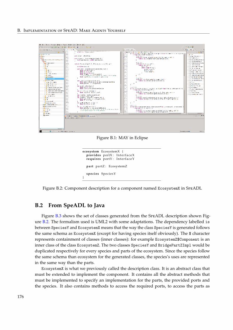
B. Implementation of SpeAD: Make Agents Yourself
Figure B.1: MAY in Eclipse
ecosystem EcosystemX {provides portX : I n t e r f a c e Xrequires portY : I n t e r f a c e Y
part partZ : EcosystemZ
species SpeciesY}
Figure B.2: Component description for a component named EcosystemX in SpeADL
B.2 From SpeADL to Java
Figure B.3 shows the set of classes generated from the SpeADL description shown Fig-ure B.2. The formalism used is UML2 with some adaptations. The dependency labelled isbetween SpeciesY and EcosystemX means that the way the class SpeciesY is generated followsthe same schema as EcosystemX (except for having species itself obviously). The $ characterrepresents containment of classes (inner classes): for example EcosystemZ$Component is aninner class of the class EcosystemZ. The two classes SpeciesY and BridgePartZImpl would beduplicated respectively for every species and parts of the ecosystem. Since the species followthe same schema than ecosystem for the generated classes, the species’s uses are representedin the same way than the parts.
EcosystemX is what we previously called the description class. It is an abstract class thatmust be extended to implement the component. It contains all the abstract methods thatmust be implemented to specify an implementation for the parts, the provided ports andthe species. It also contains methods to access the required ports, to access the parts as
176
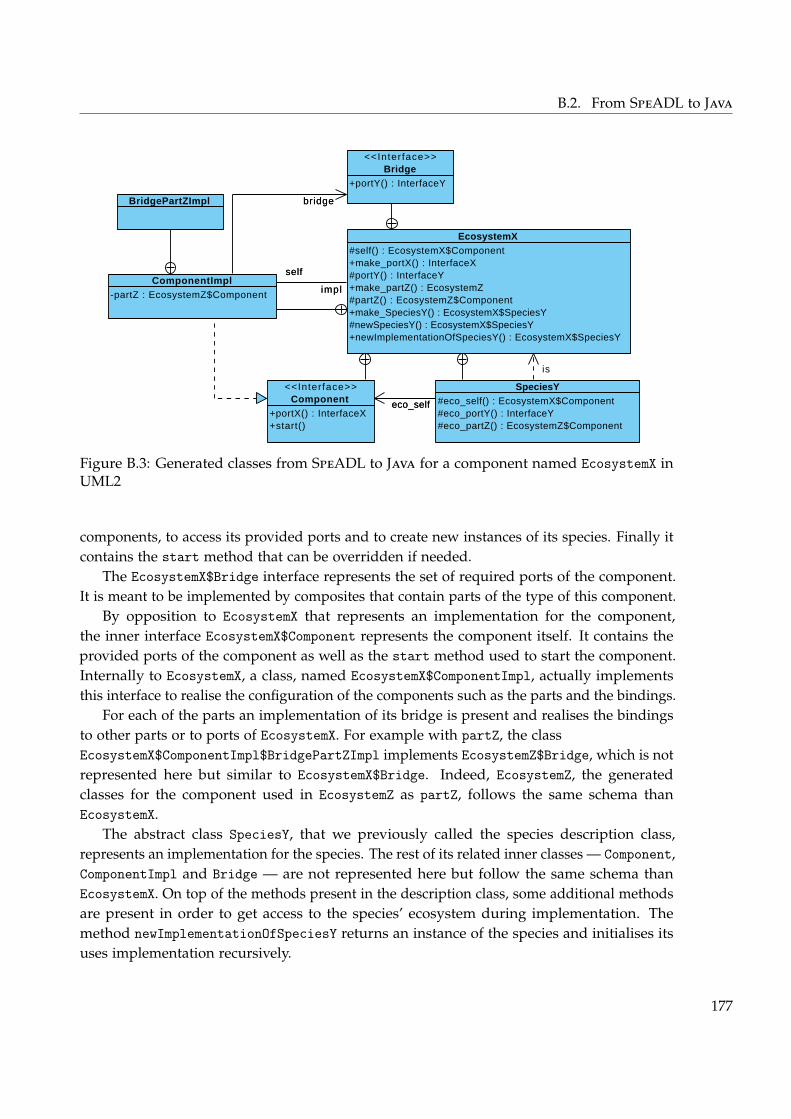
B.2. From SpeADL to Java
#self() : EcosystemX$Component+make_portX() : InterfaceX#portY() : InterfaceY+make_partZ() : EcosystemZ#partZ() : EcosystemZ$Component+make_SpeciesY() : EcosystemX$SpeciesY#newSpeciesY() : EcosystemX$SpeciesY+newImplementationOfSpeciesY() : EcosystemX$SpeciesY
EcosystemX
+portX() : InterfaceX+start()
<<Interface>>Component
+portY() : InterfaceY
<<Interface>>Bridge
-partZ : EcosystemZ$Component
ComponentImpl
#eco_self() : EcosystemX$Component#eco_portY() : InterfaceY#eco_partZ() : EcosystemZ$Component
SpeciesY
BridgePartZImpl
eco_self
bridge
self
impl
bridge
impl
self
is
eco_self
Visual Paradigm for UML Community Edition [not for commercial use]
Figure B.3: Generated classes from SpeADL to Java for a component named EcosystemX inUML2
components, to access its provided ports and to create new instances of its species. Finally itcontains the start method that can be overridden if needed.
The EcosystemX$Bridge interface represents the set of required ports of the component.It is meant to be implemented by composites that contain parts of the type of this component.
By opposition to EcosystemX that represents an implementation for the component,the inner interface EcosystemX$Component represents the component itself. It contains theprovided ports of the component as well as the start method used to start the component.Internally to EcosystemX, a class, named EcosystemX$ComponentImpl, actually implementsthis interface to realise the configuration of the components such as the parts and the bindings.
For each of the parts an implementation of its bridge is present and realises the bindingsto other parts or to ports of EcosystemX. For example with partZ, the classEcosystemX$ComponentImpl$BridgePartZImpl implements EcosystemZ$Bridge, which is notrepresented here but similar to EcosystemX$Bridge. Indeed, EcosystemZ, the generatedclasses for the component used in EcosystemZ as partZ, follows the same schema thanEcosystemX.
The abstract class SpeciesY, that we previously called the species description class,represents an implementation for the species. The rest of its related inner classes — Component,ComponentImpl and Bridge — are not represented here but follow the same schema thanEcosystemX. On top of the methods present in the description class, some additional methodsare present in order to get access to the species’ ecosystem during implementation. Themethod newImplementationOfSpeciesY returns an instance of the species and initialises itsuses implementation recursively.
177

Author’s Bibliography
French Journals
Noël, Victor, Jean-Paul Arcangeli, and Marie-Pierre Gleizes (2012). « Une approche archi-tecturale à base de composants pour l’implémentation des Systèmes Multi-Agents ». In:Revue des Nouvelles Technologies de l’Information. In press (cit. on pp. xxiii, 114).
International Conferences and Workshops
Cruz Torres, Mario Henrique, Victor Noël, Tom Holvoet, and Jean-Paul Arcangeli (2010a).« MAS Organisation at your Composite Service ». In: Proceedings of the 8th EuropeanWorkshop on Multi-Agent Systems (EUMAS’10), Paris (France). Université Paris Descartes(cit. on pp. xxiii, 114, 143).
Cruz Torres, Mario Henrique, Victor Noël, Tom Holvoet, and Jean-Paul Arcangeli (2010b).« MAS Organisation at your Composite Service ». In: Proceedings of the 3rd InternationalWorkshop on Monitoring, Adaptation and Beyond (MONA+), Ayia Napa (Cyprus). Ed. by DimkaKarastoyanova, Raman Kazhamiakin, and Andreas Metzger. ACM, pp. 33–39 (cit. onpp. xxiii, 114, 144).
Georgé, Jean-Pierre, Marie-Pierre Gleizes, Francisco Garijo, Victor Noël, and Jean-Paul Ar-cangeli (2010). « Self-adaptive Coordination for Robot Teams Accomplishing CriticalActivities ». In: Advances in Practical Applications of Agents and Multiagent Systems, 8thInternational Conference on Practical Applications of Agents and Multiagent Systems (PAAMS2010), Salamanca (Spain). Ed. by Yves Demazeau, Frank Dignum, Juan M. Corchado, andJavier Bajo. Vol. 70. Advances in Soft Computing. Springer, pp. 145–150 (cit. on p. xxiii).
Lacouture, Jérôme, Victor Noël, Jean-Paul Arcangeli, and Marie-Pierre Gleizes (2011). « En-gineering Agent Frameworks: An Application in Multi-Robot Systems ». In: Advancesin Practical Applications of Agents and Multiagent Systems, 9th International Conference onPractical Applications of Agents and Multiagent Systems (PAAMS 2011), Salamanca (Spain).Ed. by Yves Demazeau, Michal Pechoucek, Juan M. Corchado, and Javier Bajo Pérez.Advances in Intelligent and Soft Computing. Springer (cit. on pp. xxiii, 114).
179
Author’s Bibliography
Noël, Victor, Jean-Paul Arcangeli, and Marie-Pierre Gleizes (2010a). « Component-BasedAgent Architectures to Build Dedicated Agent Frameworks ». In: Proceedings of the 7thInternational Symposium “From Agent Theory to Agent Implementation” (AT2AI-7), Vienna(Austria). Ed. by Robert Trappl. Austrian Society for Cybernetic Studies, Apr. 2010, pp. 483–488 (cit. on pp. xxiii, 113).
Noël, Victor, Jean-Paul Arcangeli, and Marie-Pierre Gleizes (2010b). « Between Design andImplementation of Multi-Agent Systems: A Component-Based Two-Step Process ». In:Proceedings of the 8th European Workshop on Multi-Agent Systems (EUMAS’10), Paris (France).Université Paris Descartes, Dec. 2010 (cit. on pp. xxiii, 113).
Noël, Victor and Antonis Kakas (2009). « Gorgias-C: Extending Argumentation with ConstraintSolving ». In: Proceedings of the 10th International Conference on Logic Programming andNonmonotonic Reasoning (System Descriptions) (LPNMR 2009), Potsdam (Germany). Ed. byEsra Erdem, Fangzhen Lin, and Torsten Schaub. Vol. 5753. Lecture Notes in ComputerScience. Springer, Sept. 2009, pp. 535–541 (cit. on p. xxiii).
French Conferences and Workshops
Denis, Grégoire, Victor Noël, Jean-Paul Arcangeli, Sylvie Trouilhet, and Charles Triboulot(2012). « Composition opportuniste et ascendante à base d’agents coopératifs ». In: 8èmesJournées Francophones Mobilité et Ubiquité (UBIMOB 2012). In press (cit. on pp. xxiv, 114).
Noël, Victor and Jean-Paul Arcangeli (2011). « Frameworks, architectures et composants:revisiter le développement de systèmes multi-agents ». In: Conférence Francophone sur lesArchitectures Logicielles (CAL), Lille (France), pp. 23–32 (cit. on pp. xxiii, 114).
Noël, Victor, Sylvain Rougemaille, Jean-Paul Arcangeli, Jean-Pierre Georgé, Frédéric Migeon,and Stephane Dudouit (2009). « MAY : Make Agents Yourself. Un générateur d’API agentà base de composants ». In: Journées du GDR GPL (Session Outils et Posters) (GDR GPL),Toulouse (France). Ed. by Yves Ledru and Marc Pantel. IRIT Press, Jan. 2009, pp. 262–263(cit. on p. xxiii).
Books Parts
Lacouture, Jérôme, Ismael Rodriguez, Jean-Paul Arcangeli, Christophe Chassot, ThierryDesprats, Khalil Drira, Francisco Garijo, Victor Noël, Michelle Sibilla, and Catherine-noel Tessier (2011). « Mission-Aware Adaptive Communication for Collaborative MobileEntities ». In: Handbook of Research on Mobility and Computing: Evolving Technologies andUbiquitous Impacts. Ed. by Maria Manuela Cruz-Cunha and Fernando Moreira. IGI Global.Chap. 64, pp. 1056–1076 (cit. on p. xxiii).
180
Bibliography
Abowd, Gregory, Robert Allen, and David Garlan (1993). « Using Style to UnderstandDescriptions of Software Architecture ». In: Proceedings of SIGSOFT’93: Foundations ofSoftware Engineering. Software Engineering Notes 18(5). ACM Press, Dec. 1993, pp. 9–20(cit. on p. 8).
Agha, Gul (1986). Actors: a model of concurrent computation in distributed systems. Cambridge,MA, USA: MIT Press (cit. on p. 169).
Amor, Mercedes and Lidia Fuentes (2009). « Malaca: A Component and Aspect-OrientedAgent Architecture ». In: Information & Software Technology 51.6, pp. 1052–1065 (cit. onpp. 36, 38, 172).
Amor, Mercedes, Lidia Fuentes, and Antonio Vallecillo (2005). « Bridging the Gap BetweenAgent-Oriented Design and Implementation Using MDA ». In: Agent-Oriented SoftwareEngineering V. Ed. by James Odell, Paolo Giorgini, and Jörg Müller. Vol. 3382. LectureNotes in Computer Science. Springer Berlin / Heidelberg, pp. 93–108 (cit. on pp. 28, 38).
Arcangeli, Jean-Paul, Vincent Hennebert, Sébastien Leriche, Frédéric Migeon, and Marc Pantel(2004). JavAct. http://javact.org/. Institut de Recherche en Informatique de Toulouse,Toulouse University. Toulouse, FR. (cit. on p. 173).
Arlow, Jim and Ila Neustadt (2005). UML 2 and the Unified Process. 2nd Edition (cit. on p. 3).Bachmann, Felix, Len Bass, Charles Buhman, Santiago Comella-Dorda, Fred Long, John Robert,
Robert Seacord, and Kurt Wallnau (2000). Volume II: Technical Concepts of Component-BasedSoftware Engineering, 2nd Edition. technical CMU/SEI-2000-TR-008. Software EngineeringInstitute, Carnigie Mellon University (cit. on pp. 6, 110, 122–125, 127).
Bass, Len, Paul Clements, and Rick Kazman (2003). Software Architecture in Practice. 2nd.Boston, MA, USA: Addison-Wesley (cit. on pp. 5, 8).
Bauer, Bernhard (2002). « UML Class Diagrams Revisited in the Context of Agent-BasedSystems ». In: Agent-Oriented Software Engineering II. Ed. by Michael Wooldridge, GerhardWeiß, and Paolo Ciancarini. Vol. 2222. Lecture Notes in Computer Science. Springer Berlin/ Heidelberg, pp. 101–118 (cit. on p. 169).
Bauer, Bernhard, Jörg Müller, and James Odell (2001). « Agent UML: A Formalism forSpecifying Multiagent Software Systems ». In: Agent-Oriented Software Engineering. Ed. byPaolo Ciancarini and Michael Wooldridge. Vol. 1957. Lecture Notes in Computer Science.Springer Berlin / Heidelberg, pp. 109–120 (cit. on p. 169).
181
Bibliography
Behrens, Tristan, Rafael H. Bordini, Lars Braubach, Mehdi Dastani, Jürgen Dix, Koen Hindriks,Jomi F. Hübner, and Alexander Pokahr (2011). « An Interface for Agent-EnvironmentInteraction ». In: Proceedings of International Workshop on Programming Multi-Agent Systems(ProMAS-8). Springer (cit. on p. 36).
Bellifemine, Fabio, Agostino Poggi, and Giovanni Rimassa (1999). « JADE - A FIPA-CompliantAgent Framework ». In: 4th Proceedings of International Conference on the Practical Applicationsof Intelligent Agents, pp. 97–108 (cit. on p. 170).
Bensaid, Nourredine and Philippe Mathieu (1997). « A Hybrid and Hierarchical Multi-AgentArchitecture Model ». In: In Proceedings of PAAM’97, pp. 145–155 (cit. on p. 172).
Bergenti, Federico, Marie-Pierre Gleizes, and Franco Zambonelli, eds. (2004). Methodologiesand Software Engineering for Agent Systems. Klüwer Academic Press (cit. on pp. 17, 38).
Bernon, Carole, Valérie Camps, Marie-Pierre Gleizes, and Gauthier Picard (2005). « Engi-neering Adaptive Multi-Agent Systems: The ADELFE Methodology ». In: Agent-OrientedMethodologies. Ed. by Brian Henderson-Sellers and Paolo Giorgini. Idea Group Publishing,pp. 172–202 (cit. on pp. 11, 169).
Bernon, Carole, Massimo Cossentino, Marie-Pierre Gleizes, Paola Turci, and Franco Zam-bonelli (2005). « A Study of Some Multi-agent Meta-models ». In: Agent-Oriented SoftwareEngineering V. Ed. by James Odell, Paolo Giorgini, and Jörg Müller. Vol. 3382. LectureNotes in Computer Science. Springer Berlin / Heidelberg, pp. 62–77 (cit. on pp. 29, 38).
Bernon, Carole, Massimo Cossentino, and Juan Pavón (2005). « An overview of current trendsin european aose research ». In: Informatica 29, pp. 379–390 (cit. on p. 18).
Beydoun, Ghassan, Cesar Gonzalez-Perez, Graham Low, and Brian Henderson-Sellers (2005).« Synthesis of a generic MAS metamodel ». In: SIGSOFT Softw. Eng. Notes 30 (4 May 2005),pp. 1–5 (cit. on pp. 29, 38).
Bézivin, Jean and Olivier Gerbé (2001). « Towards a Precise Definition of the OMG/MDAFramework ». In: 16th IEEE International Conference on Automated Software Engineering (ASE2001), 26-29 November 2001, Coronado Island, San Diego, CA, USA. IEEE Computer Society,pp. 273–280 (cit. on p. 2).
Bonjean, Noélie, Carole Bernon, and Pierre Glize (2009). « Engineering Development of Agentsusing the Cooperative Behaviour of their Components ». In: MAS&S @ MALLOW’09, Turin.Ed. by Giancarlo Fortino, Massimo Cossentino, Marie-Pierre Gleizes, and Juan Pavón.Vol. 494. CEUR Workshop Proceedings (cit. on p. 113).
Bonjean, Noelie, Marie-Pierre Gleizes, Christine Maurel, and Frederic Migeon (2012). « For-ward Self-Combined Method Fragments ». In: Workshop on Agent Oriented Software Engi-neering (AOSE), Valencia, Spain, 04/06/2012-08/06/2012. Springer (cit. on p. 114).
Bordini, Rafael H., Lars Braubach, Mehdi Dastani, Amal El Fallah Seghrouchni, Jorge J. Gomez-Sanz, J. Leite, G. O’Hare, Alexander Pokahr, and Alessandro Ricci (2006). « A Survey ofProgramming Languages and Platforms for Multi-Agent Systems ». In: Informatica 30,pp. 33–44 (cit. on pp. 17, 38).
182
Bibliography
Bordini, Rafael H., Mehdi Dastani, Jürgen Dix, and Amal El Fallah Seghrouchni, eds. (2005).Multi-Agent Programming: Languages, Platforms and Applications. Vol. 15. Multiagent Systems,Artificial Societies and Simulated Organizations. Springer (cit. on p. 17).
Bordini, Rafael H., Mehdi Dastani, Jürgen Dix, and Amal El Fallah Seghrouchni, eds. (2009).Multi-Agent Programming: Languages, Tools and Applications. 1st. Springer Publishing Com-pany, Incorporated (cit. on pp. 17, 38).
Bordini, Rafael H., Jomi F. Hübner, and Michael Wooldridge (2008). Programming multi-agentsystems in AgentSpeak using Jason. Vol. 8. Wiley-Interscience (cit. on p. 170).
Bosch, Jan (2009). « From software product lines to software ecosystems ». In: Proceedings ofthe 13th International Software Product Line Conference. San Francisco, California: CarnegieMellon University, pp. 111–119 (cit. on p. 62).
Bouziane, Hinde L., Christian Pérez, and Thierry Priol (2008). « A software component modelwith spatial and temporal compositions for grid infrastructures ». In: Euro-Par 2008–ParallelProcessing, pp. 698–708 (cit. on p. 154).
Bratman, Michael E. (1999). Intention, Plans, and Practical Reason. Cambridge University Press,Mar. 1999 (cit. on p. 25).
Brazier, Frances M. T., Catholijn M. Jonker, and Jan Treur (1999). « Compositional Design andReuse of a Generic Agent Model ». In: Applied Artificial Intelligence Journal 14, pp. 491–538(cit. on pp. 36, 38).
Briot, Jean-Pierre, Thomas Meurisse, and Frédéric Peschanski (2007). « Architectural Designof Component-Based Agents: A Behavior-Based Approach ». In: Programming Multi-Agent Systems. Ed. by Rafael H. Bordini, Mehdi Dastani, Jürgen Dix, and Amal El FallahSeghrouchni. Vol. 4411. Lecture Notes in Computer Science. Springer Berlin / Heidelberg,pp. 71–90 (cit. on pp. 36, 38, 172).
Camps, Valérie, Bernard Carpuat, Marie-Pierre Gleizes, Pierre Glize, André Machonin,Christine Piquemal, Jo Link-Pezet, Christine Régis, and Sylvie Trouilhet (1994). « Versl’intelligence artificielle collective ». In: Journée Systèmes Multi-Agents du PRC-GRD I.A.,Paris, 16/12/94-16/12/94 (cit. on p. 10).
Camps, Valérie, Marie-Pierre Gleizes, and Pierre Glize (1998). « A self-organization processbased on cooperation theory for adaptive artificial systems ». In: Problems of Evolution inReal and Virtual Systems: Proceedings of the First International Conference on Philosophy andComputer Science, November 2-4, 1998. Krakow, Poland: Jagiellonian University, Universityof Mining, and Metallurgy (cit. on p. 10).
Capera, Davy, Jean-Pierre Georgé, Marie-Pierre Gleizes, and Pierre Glize (2003). « The AMASTheory for Complex Problem Solving Based on Self-organizing Cooperative Agents ».In: International Workshop on Theory And Practice of Open Computational Systems (TAPOCS).IEEE Computer Society Press, pp. 389–394 (cit. on p. 10).
Clements, Paul, Felix Bachmann, Len Bass, David Garlan, James Ivers, Reed Little, RobertNord, and Judith Stafford (2003). Documenting Software Architectures: Views and Beyond.Addison-Wesley (cit. on pp. 1, 7, 8).
183
Bibliography
Clements, Paul and Linda Northrop (2001). Software product lines. Addison-Wesley (cit. onp. 8).
Cossentino, Massimo (2005). « From requirements to code with the PASSI methodology ». In:Agent-Oriented Methodologies. Ed. by Brian Henderson-Sellers and Paolo Giorgini. IdeaGroup Publishing, pp. 79–106 (cit. on p. 169).
Cossentino, Massimo, Nicolas Gaud, Vincent Hilaire, Stéphane Galland, and AbderrafiâaKoukam (2010). « ASPECS: an agent-oriented software process for engineering complexsystems ». In: Autonomous Agents and Multi-Agent Systems 20 (2 2010), pp. 260–304 (cit. onp. 167).
Cossentino, Massimo and Valeria Seidita (2009). PASSI 2 - Going Towards Maturity of the PASSIProcess. Tech. rep. 09-02. ICAR-CNR, Dec. 2009 (cit. on p. 169).
Crnkovic, Ivica, Brahim Hnich, Torsten Jonsson, and Zeynep Kiziltan (2002). « Specification,implementation, and deployment of components ». In: Commun. ACM 45.10 (Oct. 2002),pp. 35–40. doi: 10.1145/570907.570928 (cit. on pp. 122, 124).
Crnkovic, Ivica, Séverine Sentilles, Aneta Vulgarakis, and Michel Chaudron (2011). « AClassification Framework for Software Component Models ». In: IEEE Transactions onSoftware Engineering 37.5 (Sept. 2011), pp. 593–615. doi: 10.1109/TSE.2010.83 (cit. onp. 6).
Cruz Torres, Mario Henrique and Tom Holvoet (2011a). « Composite service adaptation: aQoS-driven approach ». In: Comsware (cit. on p. 144).
Cruz Torres, Mario Henrique and Tom Holvoet (2011b). « Towards robust service workflows:a decentralized approach ». In: CoopIS - Cooperative Information Systems (cit. on p. 144).
Dalpiaz, Fabiano, Ambra Molesini, Mariachiara Puviani, and Valeria Seidita (2008). « TowardsFilling the Gap between AOSE Methodologies and Infrastructures: Requirements andMeta-model ». In: 9th Workshop "From Objects to Agents" (WOA 2008) – Evolution of AgentDevelopment: Methodologies, Tools, Platforms and Languages. Ed. by Matteo Baldoni, MassimoCossentino, Flavio De Paoli, and Valeria Seidita. Palermo, Italy: Seneca Edizioni, Nov.2008, pp. 115–121 (cit. on pp. 29, 38).
Da Silva, Joao Luis T. and Yves Demazeau (2002). « Vowels co-ordination model ». In: Proceed-ings of the first international joint conference on Autonomous agents and multiagent systems: part3. AAMAS ’02. Bologna, Italy: ACM, pp. 1129–1136 (cit. on p. 168).
Dehlinger, Josh and Robyn R. Lutz (2011). « Gaia-PL: A Product-Line Engineering Approachfor Efficiently Designing Multi-Agent Systems ». In: ACM Transactions on Software Engi-neering and Methodology (TOSEM) (cit. on pp. 24, 38).
DeLoach, Scott A. (2009). « OMACS: A framework for adaptive, complex systems ». In:Handbook of Research on Multi-Agent Systems: Semantics and Dynamics of OrganizationalModels. Ed. by Virginia Dignum. IGI Global, pp. 76–98 (cit. on p. 139).
Demazeau, Y. (1995). « From interactions to collective behaviour in agent-based systems ». In:Proceedings of the First European conference on cognitive science. Saint Malo, France, Apr. 1995,pp. 117–132 (cit. on pp. 10, 168).
184
Bibliography
Denis, Grégoire (2011). « Composition autonome et émergence au moyen d’agents-composantscoopératifs ». MA thesis. Université Paul Sabatier, June 2011 (cit. on pp. 134, 152).
Desnos, Nicolas, Marianne Huchard, Christelle Urtado, Sylvain Vauttier, and Guy Tremblay(2007). « Automated and Unanticipated Flexible Component Substitution ». In: Proceedingsof the 10th ACM SIGSOFT Symposium on Component-Based Software Engineering. Ed. byHeinz Schmidt, Ivica Crnkovic, George Heineman, and Judith Stafford. Vol. 4608. LectureNotes in Computer Science. Springer Berlin / Heidelberg, pp. 33–48. doi: 10.1007/978-3-540-73551-9_3 (cit. on p. 155).
Dignum, Virginia (2004). « A Model for Organizational Interaction: Based on Agents, Foundedin Logic ». PhD thesis. Universiteit Utrecht (cit. on p. 167).
Dignum, Virginia, ed. (2009a). Handbook of Research on Multi-Agent Systems: Semantics andDynamics of Organizational Models. IGI Global.
Dignum, Virginia (2009b). « The Role of Organization in Agent Systems ». In: Handbook ofResearch on Multi-Agent Systems: Semantics and Dynamics of Organizational Models. Ed. byVirginia Dignum. IGI Global, pp. 1–17 (cit. on p. 139).
Di Marzo Serugendo, Giovanna, Marie-Pierre Gleizes, and Anthony Karageorgos, eds. (2011).Self-organising Software. Natural Computing Series. Springer Berlin Heidelberg. doi: 10.1007/978-3-642-17348-6 (cit. on p. 135).
Eden, Amnon H. and Rick Kazman (2003). « Architecture, design, implementation ». In:Software Engineering, 2003. Proceedings. 25th International Conference on. May 2003, pp. 149–159. doi: 10.1109/ICSE.2003.1201196 (cit. on p. 8).
Ferber, Jacques (1995). Les systèmes multi-agents : vers une intelligence collective. InterEditions(cit. on pp. 9, 10).
Ferber, Jacques, Olivier Gutknecht, and Fabien Michel (2004). « From Agents to Organizations:An Organizational View of Multi-agent Systems ». In: Agent-Oriented Software EngineeringIV. Ed. by Paolo Giorgini, Jörg Müller, and James Odell. Vol. 2935. Lecture Notes inComputer Science. Springer Berlin / Heidelberg, pp. 443–459 (cit. on p. 167).
Fielding, Roy Thomas (2000). « Architectural Styles and the Design of Network-based SoftwareArchitectures ». PhD thesis (cit. on pp. 5, 123, 127).
Gamma, E., R. Helm, R. Johnson, and J. Vlissides (1995). Design Patterns: Elements of ReusableObject-Oriented Software. Professional Computing Series. A. Wesley (cit. on p. 8).
García-Magariño, Iván (2009). « Towards the Coexistence of Different Multi-Agent SystemModeling Languages with a Powertype-Based Metamodel ». In: International Symposiumon Distributed Computing and Artificial Intelligence 2008 (DCAI 2008). Ed. by Juan Corchado,Sara Rodríguez, James Llinas, and José Molina. Vol. 50. Advances in Soft Computing.Springer Berlin / Heidelberg, pp. 189–193 (cit. on pp. 29, 38).
Garlan, David, Jeffrey M. Barnes, Bradley Schmerl, and Orieta Celiku (2009). « Evolutionstyles: Foundations and tool support for software architecture evolution ». In: SoftwareArchitecture, 2009 European Conference on Software Architecture. WICSA/ECSA 2009. JointWorking IEEE/IFIP Conference on. Oct. 2009, pp. 131–140. doi: 10.1109/WICSA.2009.5290799 (cit. on p. 156).
185
Bibliography
Garlan, David, Robert T. Monroe, and David Wile (1997). « Acme: an architecture descriptioninterchange language ». In: Proceedings of the 1997 conference of the Centre for AdvancedStudies on Collaborative Research, November 10-13, 1997, Toronto, Ontario, Canada. Ed. byJ. Howard Johnson. IBM, p. 7 (cit. on p. 69).
Garlan, David and Mary Shaw (1993). « An introduction to software architecture ». In: Advancesin Software Engineering and Knowledge Engineering. Publishing Company, pp. 1–39 (cit. onp. 5).
Gaud, Nicolas, Stéphane Galland, Vincent Hilaire, and Abderrafiâa Koukam (2009). « AnOrganisational Platform for Holonic and Multiagent Systems ». In: Programming Multi-Agent Systems. Ed. by Koen Hindriks, Alexander Pokahr, and Sebastian Sardina. Vol. 5442.Lecture Notes in Computer Science. Springer Berlin / Heidelberg, pp. 104–119 (cit. onp. 171).
Georgé, Jean-Pierre, Marie-Pierre Gleizes, and Valérie Camps (2011). « Cooperation ». In:Self-organising Software. Ed. by Giovanna Di Marzo Serugendo, Marie-Pierre Gleizes, andAnthony Karageorgos. Natural Computing Series. Springer Berlin Heidelberg, pp. 193–226.doi: 10.1007/978-3-642-17348-6_9 (cit. on p. 11).
Georgé, Jean-Pierre, Gauthier Picard, Marie-Pierre Gleizes, and Pierre Glize (2003). « LivingDesign for Open Computational Systems ». In: International Workshop on Theory AndPractice of Open Computational Systems (TAPOCS at IEEE 12th International Workshop onEnabling Technologies: Infrastructure for Collaborative Enterprises (WETICE 2003) (TAPOCS),Linz, Austria, 09/06/2003-11/06/2003. http://www.computer.org: IEEE Computer Society,June 2003, pp. 389–394 (cit. on p. 30).
Georgé, J.-P., J.-P. Mano, Marie-Pierre Gleizes, M. Morel, A. Bonnot, and D. Carreras (2009).« Emergent Maritime Multi-Sensor Surveillance Using an Adaptive Multi-Agent System ».In: Cognitive systems with Interactive Sensors (COGIS), Paris. SEE/URISCA, Nov. 2009 (cit. onp. 114).
Ghosh, Debasish (2010). DSLs in action. Manning Publications Co. (cit. on pp. 4, 127).Giorgini, P., J. Mylopoulos, A. Perini, and A. Susi (2005). « The Tropos Metamodel and its
Use ». In: Informatical journal (cit. on pp. 23, 169).Girardi, Rosario and Alisson Lindoso (2006). « An Ontology-Driven Technique for the Archi-
tectural and Detailed Design of Multi-agent Frameworks ». In: Agent-Oriented InformationSystems III. Ed. by Manuel Kolp, Paolo Bresciani, Brian Henderson-Sellers, and MichaelWinikoff. Vol. 3529. Lecture Notes in Computer Science. Springer Berlin / Heidelberg,pp. 124–139 (cit. on pp. 24, 38).
Gleizes, Marie Pierre, Valérie Camps, Jean-Pierre Georgé, and Davy Capera (2008). « Engineer-ing Systems Which Generate Emergent Functionalities ». In: EEMMAS 2007. Ed. by DannyWeyns, Sven A. Brueckner, and Yves Demazeau. Vol. 5049. Lecture Notes in ComputerScience (Lecture Notes in Artificial Intelligence). Springer, pp. 58–75 (cit. on pp. 11, 169).
Gosling, James, Bill Joy, Guy Steele, and Gilad Bracha (2005). Java(TM) Language Specification,The (3rd Edition) (Java (Addison-Wesley)). Addison-Wesley (cit. on p. 123).
186
Bibliography
Greenfield, Jack and Keith Short (2003). « Software factories: assembling applications withpatterns, models, frameworks and tools ». In: Companion of the 18th annual ACM SIGPLANconference on Object-oriented programming, systems, languages, and applications. OOPSLA ’03.Anaheim, CA, USA: ACM, pp. 16–27. doi: 10.1145/949344.949348 (cit. on p. 121).
Gudgin, Martin, Marc Hadley, and Tony Rogers (2006). Web Services Addressing 1.0 - Core.World Wide Web Consortium, Recommendation REC-ws-addr-core-20060509. May 2006(cit. on p. 137).
Guivarch, Valérian, Valérie Camps, and André Péninou (2012). « Amadeus : sensibilitéau contexte et adaptation dans les systèmes ambiants par une approche multi-agentadaptative ». In: 8èmes journées francophones Mobilité et Ubiquité (UBIMOB 2012). Ed. byStéphane Lavirotte and Makhlouf Derdour (cit. on p. 114).
Gutknecht, Olivier and Jacques Ferber (2001). « The MadKit Agent Platform Architecture ».In: Infrastructure for Agents, Multi-Agent Systems, and Scalable Multi-Agent Systems. Ed. byTom Wagner and Omer Rana. Vol. 1887. Lecture Notes in Computer Science. SpringerBerlin / Heidelberg, pp. 48–55 (cit. on p. 170).
Hahn, Christian, Cristián Madrigal-Mora, and Klaus Fischer (2009). « A platform-independentmetamodel for multiagent systems ». In: Autonomous Agents and Multi-Agent Systems 18 (22009), pp. 239–266 (cit. on pp. 29, 38).
Henderson-Sellers, Brian and Paolo Giorgini, eds. (2005). Agent-Oriented Methodologies. IdeaGroup Publishing (cit. on pp. 17, 38).
Hewitt, Carl (1977). « Viewing Control Structures as Patterns of Passing Messages ». In:Artificial Intelligence 8.3, pp. 323–364 (cit. on p. 169).
Hilaire, Vincent, Abder Koukam, Pablo Gruer, and Jean-pierre Müller (2000). « FormalSpecification and Prototyping of Multi-Agent Systems ». In: In ESAW ’00: Proceedings ofthe First International Workshop on Engineering Societies in the Agent World. Springer Verlag,pp. 114–127 (cit. on p. 167).
Hindriks, Koen V., Frank S. De Boer, Wiebe Van der Hoek, and John-Jules Ch. Meyer (1999).« Agent Programming in 3APL ». In: Autonomous Agents and Multi-Agent Systems 2 (4 1999),pp. 357–401 (cit. on p. 170).
Hock-koon, Anthony A. and Mourad Oussalah (2011). « The Product-Process-Quality Frame-work ». In: 37th EUROMICRO Conference on Software Engineering and Advanced Applications,SEAA 2011, Oulu, Finland, August 30 - September 2, 2011. IEEE, pp. 20–27 (cit. on p. 134).
Hofer, Christian and Klaus Ostermann (2010). « Modular domain-specific language compo-nents in Scala ». In: Proceedings of the 9th international conference on Generative programmingand Component engineering. GPCE’10. Eindhoven, The Netherlands: ACM, pp. 83–92. doi:10.1145/1868294.1868307 (cit. on p. 129).
Howden, Nick, Ralph Rönnquist, Andrew Hodgson, and Andrew Lucas (2001). « JACKIntelligent Agents - Summary of an Agent Infrastructure ». In: In 5th International conferenceon autonomous agents (cit. on p. 170).
187
Bibliography
Hübner, Jomi F., Olivier Boissier, Rosine Kitio, and Alessandro Ricci (2010). « Instrumentingmulti-agent organisations with organisational artifacts and agents ». In: Autonomous Agentsand Multi-Agent Systems 20 (3 2010), pp. 369–400 (cit. on p. 168).
Hübner, Jomi F., Jaime S. Sichman, and O. Boissier (2007). « Developing organised multiagentsystems using the MOISE+ model: programming issues at the system and agent levels ».In: International Journal of Agent-Oriented Software Engineering 1.3, pp. 370–395 (cit. onp. 171).
Hübner, Jomi F., Jaime S. Sichman, and Olivier Boissier (2002). « A Model for the Structural,Functional, and Deontic Specification of Organizations in Multiagent Systems ». In: Ad-vances in Artificial Intelligence. Ed. by Guilherme Bittencourt and Geber Ramalho. Vol. 2507.Lecture Notes in Computer Science. Springer Berlin / Heidelberg, pp. 439–448 (cit. onp. 167).
Hübner, Jomi F., Jaime Simão Sichman, and Olivier Boissier (2006). « S-moise+: A middlewarefor developing organised multi-agent systems ». In: COIN I, volume 3913 of LNAI. Springer,pp. 64–78 (cit. on p. 171).
Huget, Marc-Philippe (2003). « Agent UML Class Diagrams Revisited ». In: Agent Technologies,Infrastructures, Tools, and Applications for E-Services. Ed. by Jaime Carbonell, Jörg Siekmann,Ryszard Kowalczyk, Jörg Müller, Huaglory Tianfield, and Rainer Unland. Vol. 2592.Lecture Notes in Computer Science. Springer Berlin / Heidelberg, pp. 49–60 (cit. onp. 169).
Ince, Darrel C., Leslie Hatton, and John Graham-Cumming (2012). « The case for opencomputer programs ». In: Nature 482.7386 (Feb. 23, 2012), pp. 485–488. doi: 10.1038/nature10836 (cit. on p. 115).
Johnson, R.E. (1997). « Frameworks = (components + patterns) ». In: Communications of theACM 40.10, pp. 39–42 (cit. on pp. 4, 121, 122, 124).
Kaddoum, Elsy (2011). « Optimisation sous contraintes de problèmes distribués par auto-organisation coopérative ». PhD thesis. Université de Toulouse, Toulouse, France, Nov.2011 (cit. on p. 114).
Kerth, N.L. and W. Cunningham (1997). « Using patterns to improve our architectural vision ».In: Software, IEEE 14.1, pp. 53–59 (cit. on p. 9).
Klügl, Franziska, Rainer Herrler, and Christoph Oechslein (2003). « From Simulated to RealEnvironments: How to Use SeSAm for Software Development ». In: Multiagent SystemTechnologies. Ed. by Michael Schillo, Matthias Klusch, Jörg Müller, and Huaglory Tianfield.Vol. 2831. Lecture Notes in Computer Science. Springer Berlin / Heidelberg, pp. 1097–1098(cit. on pp. 28, 38).
Kubera, Yoann, Philippe Mathieu, and Sébastien Picault (2008). « Interaction-Oriented AgentSimulations : From Theory to Implementation ». In: Proceedings of the 18th European Confer-ence on Artificial Intelligence (ECAI’08). Ed. by Malik Ghallab, Constantine Spyropoulos,Nikos Fakotakis, and Nikos Avouris. IOS Press, pp. 383–387 (cit. on p. 172).
188
Bibliography
Kubera, Yoann, Philippe Mathieu, and Sébastien Picault (2011). « IODA: an interaction-oriented approach for multi-agent based simulations ». In: Autonomous Agents and Multi-Agent Systems 23 (3 2011), pp. 303–343 (cit. on p. 168).
Le Goaer, Olivier, Dalila Tamzalit, Mourad Chabane Oussalah, and Abdelhak-Djamel Seriai(2008). « Evolution styles to the rescue of architectural evolution knowledge ». In: Proceed-ings of the 3rd international workshop on Sharing and reusing architectural knowledge. SHARK’08. Leipzig, Germany: ACM, pp. 31–36 (cit. on p. 156).
Leriche, Sebastien (2006). « Architectures à composants et agents pour la conception d’applicationsréparties adaptables ». PhD thesis. Université Paul Sabatier, Toulouse, France (cit. on p. xxi).
Leriche, Sébastien and Jean-Paul Arcangeli (2010). « Flexible Architectures of Adaptive Agents: the Agent-Phi Approach ». In: International Journal of Grid Computing and Multi-AgentSystems 1.1 (Jan. 2010), pp. 51–71 (cit. on p. xxi).
Loiret, Frédéric, Romain Rouvoy, Lionel Seinturier, and Philippe Merle (2011). « SoftwareEngineering of Component-Based Systems-of-Systems: A Reference Framework ». In: 14thInternational ACM SIGSOFT Symposium on Component-Based Software Engineering (CBSE’11).Ed. by Springer. June 2011, pp. 61–65 (cit. on p. 129).
Louloudi, Athanasia and Franziska Klügl (2011). « Towards a Generic Connection BetweenAgent Behaviour and Visualisation ». In: Proceedings of the 9th European Workshop onMulti-Agent Systems (EUMAS’11). Maastricht University (cit. on p. 37).
Magee, J. and J. Kramer (1996). « Dynamic structure in software architectures ». In: ACMSIGSOFT Software Engineering Notes. Vol. 21. 6. ACM, pp. 3–14. doi: 10.1145/250707.239104 (cit. on p. 122).
Mariachiara, Puviani, Massimo Cossentino, Giacomo Cabri, and Ambra Molesini (2010).« Building an agent methodology from fragments: the MEnSA experience ». In: Proceedingsof the 2010 ACM Symposium on Applied Computing. SAC ’10. ACM, pp. 920–927 (cit. onpp. 28, 38).
Markiewicz, Marcus Eduardo and Carlos J. P. de Lucena (2001). « Object Oriented FrameworkDevelopment ». In: Crossroads 7 (4 July 2001), pp. 3–9. doi: http://doi.acm.org/10.1145/372765.372771 (cit. on pp. 4, 121).
Medvidovic, N. and R.N. Taylor (2000). « A classification and comparison framework forsoftware architecture description languages ». In: Software Engineering, IEEE Transactionson 26.1 (Jan. 2000), pp. 70–93 (cit. on pp. 6, 55).
Molesini, Ambra, Enrico Denti, and Andrea Omicini (2007). « From AOSE Methodologies toMAS Infrastructures: The SODA Case Study ». In: 8th International Workshop “EngineeringSocieties in the Agents World” (ESAW’07). Ed. by Alexander Artikis, Gregory O’Hare, KostasStathis, and George Vouros. Workshop Notes. Athens, Greece: NCSR “Demokritos”, Oct.2007, pp. 283–298 (cit. on pp. 28, 38).
Molesini, Ambra, Andrea Omicini, Enrico Denti, and Alessandro Ricci (2006). « SODA: ARoadmap to Artefacts ». In: Engineering Societies in the Agents World VI. Ed. by OguzDikenelli, Marie-Pierre Gleizes, and Alessandro Ricci. Vol. 3963. Lecture Notes in Com-puter Science. Springer Berlin / Heidelberg, pp. 49–62 (cit. on p. 168).
189
Bibliography
Monroe, R.T., A. Kompanek, R. Melton, and D. Garlan (1997). « Architectural styles, designpatterns, and objects ». In: Software, IEEE 14.1, pp. 43–52. doi: 10.1109/52.566427 (cit. onpp. 8, 123, 124).
Morin, A., J. Urban, P. D. Adams, I. Foster, A. Sali, D. Baker, and P. Sliz (2012). « ShiningLight into Black Boxes ». In: Science 336.6078 (Apr. 13, 2012), pp. 159–160. doi: 10.1126/science.1218263 (cit. on p. 115).
Nunes, Ingrid, Carlos de Lucena, Uirá Kulesza, and Camila Nunes (2011). « On the De-velopment of Multi-agent Systems Product Lines: A Domain Engineering Process ». In:Agent-Oriented Software Engineering X. Ed. by Marie-Pierre Gleizes and Jorge Gomez-Sanz.Vol. 6038. Lecture Notes in Computer Science. Springer Berlin / Heidelberg, pp. 125–139(cit. on pp. 24, 38).
Nuseibeh, B. (2001). « Weaving together requirements and architectures ». In: Computer 34.3(Mar. 2001), pp. 115 –119. doi: 10.1109/2.910904 (cit. on p. 7).
Oechslein, Christoph, Franziska Klügl, Rainer Herrler, and Frank Puppe (2001). « UML forBehavior-Oriented Multi-Agent Simulations ». In: in Multi-Agent Systems LNAI; SecondInternational Workshop of Central and Eastern Europe on MultiAgent Systems, CEEMAS 2001,pp. 26–29 (cit. on p. 168).
Oluyomi, A. (2006). « Protocols and patterns for agent-oriented software development ».PhD thesis. University of Melbourne (cit. on pp. 25, 35, 38).
Oluyomi, Ayodele, Shanika Karunasekera, and Leon Sterling (2007). « A comprehensive viewof agent-oriented patterns ». In: Autonomous Agents and Multi-Agent Systems 15 (3 2007),pp. 337–377 (cit. on pp. 25, 35, 38).
Papazoglou, Michael P., Paolo Traverso, Schahram Dustdar, and Frank Leymann (2007).« Service-Oriented Computing: State of the Art and Research Challenges ». In: Computer40.11, pp. 38–45. doi: 10.1109/MC.2007.400 (cit. on p. 136).
Pavón, Juan, Jorge J. Gómez-Sanz, and Rubén Fuentes (2005). « The INGENIAS Methodologyand Tools ». In: Agent-Oriented Methodologies. Ed. by Brian Henderson-Sellers and PaoloGiorgini. Idea Group Publishing, pp. 236–276 (cit. on pp. 28, 38, 169).
Pavón, Juan, Jorge J. Gómez-Sanz, and Rubén Fuentes (2006). « Model Driven Development ofMulti-Agent Systems ». In: Model Driven Architecture – Foundations and Applications. Ed. byArend Rensink and Jos Warmer. Vol. 4066. Lecture Notes in Computer Science. SpringerBerlin / Heidelberg, pp. 284–298 (cit. on pp. 28, 38).
Peña, Joaquin, Michael G. Hinchey, Manuel Resinas, Roy Sterritt, and James L. Rash (2007).« Designing and managing evolving systems using a MAS product line approach ». In: Sci.Comput. Program. 66 (1 Apr. 2007), pp. 71–86 (cit. on pp. 24, 38).
Pereira, Jorge Verissimo (2009). « The new supply chain’s frontier: Information management ».In: International Journal of Information Management 29.5, pp. 372–379. doi: 10.1016/j.ijinfomgt.2009.02.001 (cit. on p. 136).
Perry, Dewayne and Alexander L. Wolf (1992). « Foundations for the Study of SoftwareArchitecture ». In: ACM SIGSOFT Software Engineering Notes 17, pp. 40–52 (cit. on p. 5).
190
Bibliography
Pokahr, Alexander, Lars Braubach, and Winfried Lamersdorf (2005). « Jadex: A BDI Reason-ing Engine ». In: Multi-Agent Programming: Languages, Platforms and Applications. Ed. byRafael H. Bordini, Mehdi Dastani, Jürgen Dix, and Amal El Fallah Seghrouchni. Vol. 15.Multiagent Systems, Artificial Societies and Simulated Organizations. Springer, pp. 149–174 (cit. on p. 170).
Poslad, Stefan and Patricia Charlton (2006). « Standardizing Agent Interoperability: TheFIPA Approach ». In: Multi-Agent Systems and Applications. Ed. by Michael Luck, VladimírMarík, Olga Štepánková, and Robert Trappl. Vol. 2086. Lecture Notes in Computer Science.Springer Berlin / Heidelberg, pp. 98–117 (cit. on p. 169).
Rao, Anand (1996). « AgentSpeak(L): BDI agents speak out in a logical computable language ».In: Agents Breaking Away. Ed. by Walter Van de Velde and John Perram. Vol. 1038. LectureNotes in Computer Science. Springer Berlin / Heidelberg, pp. 42–55 (cit. on p. 170).
Reed, P (2002). « Reference Architecture: The best of best practices ». In: The Rational Edge(cit. on p. 9).
Ricci, Alessandro, Viroli Mirko, and Piancastelli Giulio (2011). « simpA: An agent-orientedapproach for programming concurrent applications on top of Java ». In: Science of ComputerProgramming 76.1 (Jan. 2011). Ed. by Pascal Poizat Mirko Viroli Carlos Canal, pp. 37–62(cit. on p. 171).
Ricci, Alessandro, Mirko Viroli, and Andrea Omicini (2007). « CArtAgO: A Framework forPrototyping Artifact-Based Environments in MAS ». In: Environments for Multi-AgentSystems III. Ed. by Danny Weyns, H. Parunak, and Fabien Michel. Vol. 4389. Lecture Notesin Computer Science. Springer Berlin / Heidelberg, pp. 67–86 (cit. on pp. 36, 171).
Ricci, Alessandro, Mirko Viroli, and Andrea Omicini (2008). « The A&A Programming Modeland Technology for Developing Agent Environments in MAS ». In: Programming Multi-Agent Systems. Ed. by Mehdi Dastani, Amal El Fallah Seghrouchni, Alessandro Ricci,and Michael Winikoff. Vol. 4908. Lecture Notes in Computer Science. Springer Berlin /Heidelberg, pp. 89–106 (cit. on p. 168).
Ricordel, Pierre-Michel and Yves Demazeau (2002). « Volcano, a Vowels-Oriented Multi-agentPlatform ». In: From Theory to Practice in Multi-Agent Systems. Ed. by Barbara Dunin-Kepliczand Edward Nawarecki. Vol. 2296. Lecture Notes in Computer Science. Springer Berlin /Heidelberg, pp. 742–742 (cit. on pp. 36, 38).
Rougemaille, Sylvain, Jean-Paul Arcangeli, Marie-Pierre Gleizes, and Frédéric Migeon (2009).« ADELFE Design, AMAS-ML in Action: A Case Study ». In: Post-Proceedings of the Interna-tional Workshop on Engineering Societies in the Agents World (ESAW 2008). Vol. 5485. LectureNotes in Computer Science (Lecture Notes in Artificial Intelligence). Springer, pp. 97–112(cit. on pp. 28, 38, 50).
Routier, Jean-Christophe, Philippe Mathieu, and Yann Secq (2001). « Dynamic Skills Learning:A Support to Agent Evolution ». In: Proceedings of the Artificial Intelligence and the Simulationof Behaviour, Symposium on Adaptive Agents and Multi-agent systems (AISB’01). Ed. by DanielKudenko and Eduardo Alonso (cit. on pp. 36, 38, 172).
191

Bibliography
Schelfthout, K., T. Coninx, A. Helleboogh, T. Holvoet, E. Steegmans, and D. Weyns (2002).« Agent Implementation Patterns ». In: Proceedings of the Workshop on Agent-Oriented Method-ologies, 17th Annual ACM Conference on Object-Oriented Programming, Systems, Languages,and Applications (OOPSLA’02), pp. 119–130 (cit. on pp. 35, 37, 38).
Sellami, Zied and Valérie Camps (2012). « DYNAMO-MAS: A Multi-Agent System for Build-ing and Evolving Ontologies from Texts (short paper) ». In: International Conference onPractical Applications of Agents and Multiagent Systems (PAAMS), Salamanca, 28/03/2012-30/03/2012. Vol. 155. 4240. Springer, pp. 283–286 (cit. on p. 113).
Shoham, Y. (1993). « Agent-oriented programming ». In: Artificial intelligence 60.1, pp. 51–92(cit. on p. 25).
Silva, C., P. Tedesco, J. Castro, and R. Pinto (2004). « Comparing agent-oriented methodologiesusing NFR approach ». In: IEE Seminar Digests 2004.916, pp. 1–9 (cit. on pp. 22, 38).
Sommerville, I., D. Cliff, R. Calinescu, J. Keen, T. Kelly, M. Kwiatkowska, J. McDermid,and R. Paige (2011). « Large-scale Complex IT Systems ». In: ArXiv e-prints (Sept. 2011).arXiv:1109.3444 [cs.SE] (cit. on p. 135).
Stratulat, Tiberiu, Jacques Ferber, and John Tranier (2009). « MASQ: towards an integralapproach to interaction ». In: Proceedings of The 8th International Conference on AutonomousAgents and Multiagent Systems - Volume 2. Ed. by Carles Sierra, Cristiano Castelfranchi,Keith Decker, and Jaime Sichman. AAMAS ’09. International Foundation for AutonomousAgents and Multiagent Systems, pp. 813–820 (cit. on p. 168).
Sudeikat, Jan, Lars Braubach, Alexander Pokahr, and Winfried Lamersdorf (2005). « Evaluationof Agent-Oriented Software Methodologies – Examination of the Gap Between Modelingand Platform ». In: Agent-Oriented Software Engineering V. Ed. by James Odell, PaoloGiorgini, and Jörg Müller. Vol. 3382. Lecture Notes in Computer Science. Springer Berlin /Heidelberg, pp. 126–141 (cit. on pp. 28, 38).
Sykes, Daniel, Jeff Magee, and Jeff Kramer (2011). « FlashMob: distributed adaptive self-assembly ». In: 2011 ICSE Symposium on Software Engineering for Adaptive and Self-ManagingSystems, SEAMS 2011, Waikiki, Honolulu , HI, USA, May 23-24, 2011. Ed. by Holger Gieseand Betty H. C. Cheng. ACM, pp. 100–109 (cit. on p. 135).
Szyperski, C., D. Gruntz, and S. Murer (2002). Component Software: Beyond Object-OrientedProgramming. Addison-Wesley / ACM Press (cit. on pp. 5, 6).
Taillandier, Patrick, Alexis Drogoul, Duc-An Vo, and Edouard Amouroux (2010). « GAMA: asimulation platform that integrates geographical information data, agent-based modelingand multi-scale control ». In: The 13th International Conference on Principles and Practices inMulti-Agent Systems (PRIMA). India (cit. on p. 172).
Trencansky, Ivan and Radovan Cervenka (2005). « Agent Modeling Language (AML): AComprehensive Approach to Modeling MAS ». In: Informatica 29, pp. 391–400 (cit. onp. 169).
Van Roy, Peter (2007). « Self Management and the Future of Software Design ». In: ElectronicNotes in Theoretical Computer Science 182. Proceedings of the Third International Workshop
192
Bibliography
on Formal Aspects of Component Software (FACS 2006), pp. 201 –217. doi: 10.1016/j.entcs.2006.12.043 (cit. on p. 135).
Van Roy, Peter (2009). « Programming Paradigms for Dummies: What Every ProgrammerShould Know ». In: New Computational Paradigms for Computer Music. Ed. by GérardAssayag and Andrew Gerzso. France: IRCAM/Delatour (cit. on p. 3).
Van Roy, Peter and Seif Haridi (2004). Concepts, Techniques, and Models of Computer Programming.MIT Press, Mar. 2004 (cit. on pp. 119, 127).
Viroli, Mirko, Tom Holvoet, Alessandro Ricci, Kurt Schelfthout, and Franco Zambonelli (2007).« Infrastructures for the environment of multiagent systems ». In: Autonomous Agents andMulti-Agent Systems 14 (1 2007), pp. 49–60 (cit. on pp. 25, 35, 38).
Weiser, Mark (1991). « The Computer for the 21st Century ». In: Scientific American 256.3,pp. 66–75 (cit. on p. 145).
Weyns, Danny (2010). Architecture-Based Design of Multi-Agent Systems. 1st. Springer PublishingCompany, Incorporated (cit. on pp. 9, 23, 35, 38).
Weyns, Danny, Robrecht Haesevoets, and Alexander Helleboogh (2010). « The MACODOorganization model for context-driven dynamic agent organizations ». In: ACM Trans.Auton. Adapt. Syst. 5 (4 Nov. 2010), 16:1–16:29 (cit. on pp. 139, 167).
Weyns, Danny, Alexander Helleboogh, Elke Steegmans, Tom De Wolf, Koenraad Mertens,Nelis Boucké, and Tom Holvoet (2004). « Agents are not part of the problem, agents cansolve the problem ». In: Proceedings of the OOPSLA Workshop on Agent-Oriented Methodologies,pp. 101–102 (cit. on pp. 9, 30, 36).
Weyns, Danny and Tom Holvoet, eds. (2006). Multiagent Systems and Software Architecture(MASSA) (cit. on pp. 19, 23, 28).
Weyns, Danny, Andrea Omicini, and James Odell (2006). « Environment as a first classabstraction in multiagent systems ». In: Autonomous Agents and Multi-Agent Systems 14.1,pp. 5–30. doi: 10.1007/s10458-006-0012-0 (cit. on pp. 25, 35, 38).
Wilensky, Uri (1999). NetLogo itself. http://ccl.northwestern.edu/netlogo/. Center forConnected Learning and Computer-Based Modeling, Northwestern University. Evanston,IL. (cit. on p. 172).
Zambonelli, Franco, Nicholas R. Jennings, and Michael Wooldridge (2003). « Developingmultiagent systems: The Gaia methodology ». In: ACM Trans. Softw. Eng. Methodol. 12 (3July 2003), pp. 317–370 (cit. on p. 169).
Zyda, Michael (2005). « From visual simulation to virtual reality to games ». In: Computer 38.9(Sept. 2005), pp. 25 –32. doi: 10.1109/MC.2005.297 (cit. on p. 91).
193

Victor Noël
Component-based Software Architectures and Multi-AgentSystems: Mutual and Complementary Contributions for
Supporting Software Development
Thesis Supervisor:Marie-Pierre Gleizes — Professor, University of Toulouse, France
Jean-Paul Arcangeli — Maître de Conférences, HDR, University of Toulouse, France
PhD defended June 15, 2012 at IRIT - Université Paul Sabatier
Abstract
In this thesis, we explore the various aspects of the mutual and complementary con-tributions that multi-agent systems (MASs) and component-based software architectures(CBSAs) can provide to each other. On one hand, we define, illustrate, analyse and discussan architecture-oriented methodology of MAS development, a component model (SpeAD),an architectural description language (SpeADL) and a design method (SpEArAF) that easeand guide the description and the implementation of MASs. This complete answer to MASdevelopment is supported by a tool (MAY) and has been applied to many applications. Onthe other hand, we explore through various experiments how self-adaptive MASs can be usedto support CBSAs. The agents and their continuous reorganisation act both as the engineof the construction and of the dynamic adaptation of the architecture, and as the runtimecontainer that practically connects its elements together.
Keywords:
Discipline: Informatique
Institut de Recherche en Informatique de Toulouse — UMR 5505Université Paul Sabatier, 118 route de Narbonne, 31 062 Toulouse Cedex 4, France
Victor Noël
Architectures logicielles à base de composants et systèmesmulti-agents : contributions mutuelles et complémentaires pour
supporter le développement logiciel
Directeurs de thèse :Marie-Pierre Gleizes — Professeur, Université de Toulouse, France
Jean-Paul Arcangeli — Maître de Conférences, HDR, Université de Toulouse, France
Thèse soutenue le 15 juin 2012 à l’IRIT — Université Paul Sabatier
Résumé
Dans cette thèse, nous explorons les diverses contributions que les systèmes multi-agents(SMA) et les architectures à base de composants (CBSA) peuvent mutuellement et complé-mentairement s’apporter l’un à l’autre. Dans un premier temps, nous définissons, illustrons,analysons et discutons une méthodologie du développement des SMA, un modèle de com-posants (SpeAD), un langage de description d’architecture (SpeADL) et une méthode deconception (SpEArAF) qui facilitent et guident la description et l’implémentation des SMA.Cette réponse complète au développement des SMA est assistée par un outil (MAY) et a étéappliquée à un grand nombre d’applications. Dans un second temps, nous explorons à traversdivers expériences l’aide que peuvent apporter les SMA auto-adaptatif aux CBSA. Les agentset leur réorganisation continuelle jouent à la fois le rôle de moteur de la construction et del’adaptation dynamique de l’architecture, mais aussi du conteneur qui connecte ses élémentsen pratique.
Mots-clés :
Discipline : Informatique
Institut de Recherche en Informatique de Toulouse — UMR 5505Université Paul Sabatier, 118 route de Narbonne, 31 062 Toulouse Cedex 4