Embed Size (px)
Citation preview
Centrifugal instability of Stokes layers in crossflow:
the case of a forced cylinder wake
Juan D’Adamo
1
, Ramiro Godoy-Diana
2
& José Eduardo Wesfreid
2
1Facultad de Ingeniería Universidad de Buenos Aires (CONICET), Av. Paseo Colón 850,C1063ACV - Buenos Aires - Argentina.
2Physique et Mécanique des Milieux Hetérogènes (PMMH), CNRS UMR 7636; ESPCIParisTech; UPMC; Univ. Paris Diderot (Paris 7), 10 rue Vauquelin, 75005 Paris, France
Abstract
The wake flow around a circular cylinder at Re ⇡ 100 performing rotatory oscillations
has been thoroughly discussed in the literature, mostly focusing on the modifications to the
natural Bénard-von Kármán vortex street that result from the forced shedding modes locked
to the rotatory oscillation frequency. The usual experimental and theoretical frameworks at
these Reynolds numbers are quasi-two-dimensional, since the secondary instabilities bring-
ing a three-dimensional structure to the cylinder wake flow occur only at higher Reynolds
numbers. In the present paper we show that a three-dimensional structure can appear
below the usual three-dimensionalization threshold, when forcing with frequencies lower
than the natural vortex shedding frequency, at high amplitudes, as a result of a previously
unreported mechanism: a pulsed centrifugal instability of the oscillating Stokes layer at
the wall of the cylinder. The present numerical investigation lets us in this way propose
a physical explanation for the turbulence-like features reported in the recent experimental
study of D’Adamo et al. (2011).
1 Introduction
A circular cylinder performing rotational oscillations around its axis in an infinite viscous fluidproduces an axisymmetric pulsed boundary layer, called a Stokes layer. This is a flow susceptibleto generate centrifugal instabilities. The linear stability problem of this flow configuration hasbeen studied by Hall (1975); Seminara and Hall (1976) using asymptotic methods. A thresholdfor the appearance of three-dimensional (3D) axisymmetric instability modes was determined.Riley and Laurence (1976) did also stability calculations not directly on the Stokes layer problembut considering the modulated circular Couette flow under axisymmetric disturbances, in thenarrow-gap limit. Later, Aouidef et al. (1994); Ern (1998); Ern and Wesfreid (1999, 2002)considered this flow as a limit case for the stability problem of the classic geometry of twoconcentric cylinders with oscillation: the Taylor-Couette configuration (see e.g. Chandrasekhar(1981) for a review). In both cases, the control parameter is the Taylor number, defined as
T = Ri
rd
R (1)
where Ri
= !i
ri
d/⌫ is a Reynolds number based on the rotational angular velocity of the cylinder!i
. We keep the notation of the Taylor-Couette configuration, where the subscript i stands for
1
arX
iv:1
504.
0622
9v1
[phy
sics.f
lu-d
yn]
23 A
pr 2
015
Figure 1: Different flow states for the forcing parameters (f,A) scrutinised in D’Adamo et al.(2011). Visualisations are from Thiria et al. (2006). Solid lines represent the threshold fromglobal to convective instability. The dotted line indicates the threshold to centrifugal instabilityof the Stokes layer of an oscillating cylinder without a crossflow given by T
c
= 165, from Seminaraand Hall (1976). Symbols F show the threshold for 3D centrifugal instabilities observed in the3D DNS discussed in Figs. 5(b) and 5(c). Dashed region stands for states with turbulent-likebehaviour described in D’Adamo et al. (2011).
inner cylinder, ri
thus being the radius of the cylinder. In addition, R is the local radius ofcurvature and ⌫ the kinematic viscosity. The characteristic length scale d in the Taylor-Couettecase is the gap between the cylinders, which fixes the scale of the wavelength of the primaryinstability. For the case studied by Seminara and Hall (1976), however, the instability occursin the inner Stokes boundary layer of thickness �
S
=
p⌫/!
i
around the oscillating cylinder.They have determined analytically, numerically and experimentally the critical values for Tassociated with the onset of a Taylor-Couette-type vortex flow. Vortices evenly spaced, with acritical length �
c
in the cylinder axial direction which is proportional to �S
, are thus developed.
On the other hand, when a uniform flow comes across a cylinder, a prototypical 2D wake flowtakes place for moderate free-stream Reynolds numbers Re = DU
0
/⌫, where D is the diameterof the cylinder, U
0
the free-stream velocity. The well-known Bénard-von Kármán (BvK) vortexstreet (Bénard, 1908; von Kármán, 1911) results from the destabilisation of the steady flow inthe wake of the cylinder and produces the periodic shedding of opposite-signed vortices with afrequency f
0
, that occurs above the threshold Rec
⇡ 47 (see e.g. Provansal et al. (1987); Jackson(1987)). This flow is quasi-two dimensional up to Re . 180. In a recent work (D’Adamo et al.,2011), we studied experimentally the problem of the forced wake performing rotary oscillationsat Re = 100. The rotational oscillation of the cylinder is prescribed by a forcing function offrequency f and amplitude ✓
0
that can be written as ✓(t) = ✓0
cos(2⇡ft), which allows theforcing to be unequivocally described using two independent non-dimensional parameters as didby Taneda (1978): the forcing amplitude A = u
✓max
/U0
, where u✓max
= D⇡f✓0
is the maximalazimuthal velocity of the rotational oscillation, and the ratio f/f
0
. We characterised the spatialdevelopment of the flow and its stability properties following previous studies by Thiria et al.
2
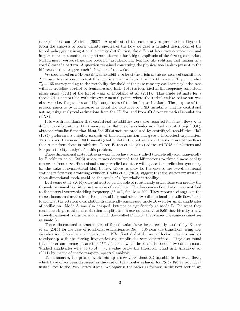
(2006); Thiria and Wesfreid (2007). A synthesis of the case study is presented in Figure 1.From the analysis of power density spectra of the flow we gave a detailed description of theforced wake, giving insight on the energy distribution, the different frequency components, andin particular on a continuous spectrum observed for a high amplitude of the forcing oscillation.Furthermore, vortex structures revealed turbulence-like features like splitting and mixing in aspatial cascade pattern. A question remained concerning the physical mechanism present in thebifurcation that triggers such behaviour of the wake.
We speculated on a 3D centrifugal instability to be at the origin of this sequence of transitions.A natural first attempt to test this idea is shown in figure 1, where the critical Taylor numberTc
= 165 corresponding to the instability threshold of the pure rotatory oscillating cylinder casewithout crossflow studied by Seminara and Hall (1976) is identified in the frequency-amplitudephase space (f,A) of the forced wake of D’Adamo et al. (2011). This crude estimate for athreshold is compatible with the experimental points where the turbulent-like behaviour wasobserved (low frequencies and high amplitudes of the forcing oscillation). The purpose of thepresent paper is to characterize in detail the existence of a 3D instability and its centrifugalnature, using analytical estimations from the 2D flow and from 3D direct numerical simulations(DNS).
It is worth mentioning that centrifugal instabilities were also reported for forced flows withdifferent configurations. For transverse oscillations of a cylinder in a fluid at rest, Honji (1981),obtained visualizations that identified 3D structures produced by centrifugal instabilities. Hall(1984) performed a stability analysis of this configuration and gave a theoretical explanation.Tatsuno and Bearman (1990) investigated in detail the patterns and the structure of the flowsthat result from these instabilities. Later, Elston et al. (2004) addressed DNS calculations andFloquet stability analysis for this problem.
Three dimensional instabilities in wake flows have been studied theoretically and numericallyby Blackburn et al. (2005) where it was determined that bifurcations to three-dimensionalitycan occur from a two-dimensional time-periodic base state with space–time reflection symmetryfor the wake of symmetrical bluff bodies. More recently for the case of the two-dimensionalstationary flow past a rotating cylinder, Pralits et al. (2013) suggest that the stationary unstablethree-dimensional mode could be the result of a hyperbolic instability.
Lo Jacono et al. (2010) were interested on the role of rotationally oscillations can modify thethree-dimensional transition in the wake of a cylinder. The frequency of oscillation was matchedto the natural vortex-shedding frequency, f+
= 1, for Re = 300. They reported changes on thethree dimensional modes from Floquet stability analysis on two-dimensional periodic flow. Theyfound that the rotational oscillation dramatically suppressed mode B, even for small amplitudesof oscillation. Mode A was also damped, but not as significantly as mode B. For what theyconsidered high rotational oscillation amplitudes, in our notation A ' 0.66 they identify a newthree-dimensional transition mode, which they called D mode, that shares the same symmetriesas mode A.
Three dimensional characteristics of forced wakes have been recently studied by Kumaret al. (2013) for the case of rotational oscillations at Re = 185 near the transition, using flowvisualization, hot-wire anemometry and PIV. Spatial distribution of lock-on regions and itsrelationship with the forcing frequencies and amplitudes were determined. They also foundthat for certain forcing parameters (f+, A), the flow can be forced to become two-dimensional.Studied amplitudes were up to A = ⇡, a value below the threshold found in D’Adamo et al.(2011) by means of spatio-temporal spectral analysis.
To summarise, the present work sets up a new view about 3D instabilities in wake flows,which have often been discussed in the case of the circular cylinder for Re > 180 as secondaryinstabilities to the BvK vortex street. We organise the paper as follows: in the next section we
3
(a) (b)
Ly
=
Lx
=
(c)
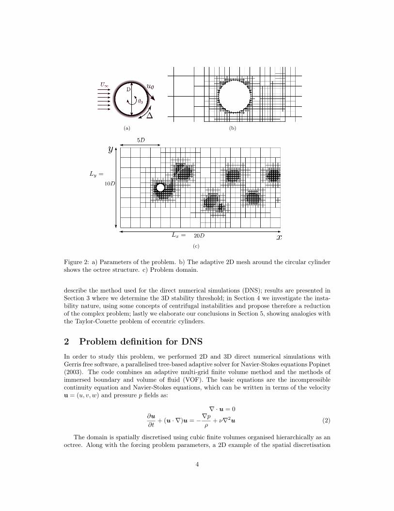
Figure 2: a) Parameters of the problem. b) The adaptive 2D mesh around the circular cylindershows the octree structure. c) Problem domain.
describe the method used for the direct numerical simulations (DNS); results are presented inSection 3 where we determine the 3D stability threshold; in Section 4 we investigate the insta-bility nature, using some concepts of centrifugal instabilities and propose therefore a reductionof the complex problem; lastly we elaborate our conclusions in Section 5, showing analogies withthe Taylor-Couette problem of eccentric cylinders.
2 Problem definition for DNS
In order to study this problem, we performed 2D and 3D direct numerical simulations withGerris free software, a parallelised tree-based adaptive solver for Navier-Stokes equations Popinet(2003). The code combines an adaptive multi-grid finite volume method and the methods ofimmersed boundary and volume of fluid (VOF). The basic equations are the incompressiblecontinuity equation and Navier-Stokes equations, which can be written in terms of the velocityu = (u, v, w) and pressure p fields as:
r · u = 0
@u
@t+ (u ·r)u = �rp
⇢+ ⌫r2u (2)
The domain is spatially discretised using cubic finite volumes organised hierarchically as anoctree. Along with the forcing problem parameters, a 2D example of the spatial discretisation
4
is given in Figure 2. The flow domain, shown in Figure 2(c) is Lx
⇥ Ly
= 20D ⇥ 10D for 2Dsimulations and L
z
= 20D for the spanwise direction in 3D simulations. As detailed in Popinet(2003) the mesh can be refined near the solid boundary and it can use vorticity gradients as anadaptive criterion. A cell is refined whenever:
|r⇥ u|�x
max |u| > ⇠ (3)
where �x is the size of the cell and ⇠ is a user-defined threshold which can be interpreted asthe maximum angular deviation (caused by the local vorticity) of a particle travelling at speedmax |u|. This adaptive criterion is represented in Figure 2(b) and 2(c) where different box sizesare noticeable. In order to reveal BvK vortices as well as centrifugal structures, we choose aminimum grid size of D/51.2 for the solid boundary and D/12.8 to define vortex regions. The ⇠threshold is set to 0.05 for 3D simulations and to 0.01 for 2D simulations. The flow parametersof the simulations are defined in order to match the experimental case of D’Adamo et al. (2011):Cross flow velocity U1 = 1, kinematic viscosity ⌫ = 10
�3 and cylinder diameter D = 0.1, givinga Reynolds number Re = 100.
The boundary conditions are: u = 1 for x = �5D; u = 1 for y = ±5; the outflow conditionis @v/@x = 0 and p = 0 for x = 15D; for 3D simulations, a symmetry condition is usedfor the flow at z = 20D; and at the cylinder surface, u = u
solid
where usolid
depends onthe forcing. As depicted in Figure 2(a) rotatory oscillations are characterised by an angularcoordinate ✓(t) = ✓
0
cos(↵), where the forcing phase is ↵ = 2⇡ff
t, and tangential displacements� = u
✓
/(2⇡ff
). Given f0
the natural frequency of vortex shedding, the forcing frequency ff
iswritten in dimensionless form as f+
= ff
/f0
. A non-dimensional number for the amplitude ofoscillations is obtained by comparing the maximum tangential velocity u
✓max
and the free flowvelocity, A = u
✓max
/U1.
3 Results of the numerical simulation
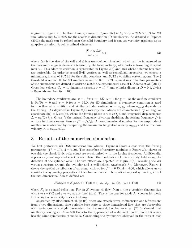
We first performed 3D DNS numerical simulations. Figure 3 shows a case with the forcingparameters (f+
= 0.75, A = 4.00). The isosurface of vorticity modulus in Figure 3(a) shows onone side the classic BvK wake structure synchronised with the forcing frequency. Additionally,a previously not reported effect is also clear: the modulation of the vorticity field along thedirection of the cylinder axis. The two effects are depicted in Figure 3(b), revealing the 3Dvortex structure around the cylinder and a well-defined wavelength �
z
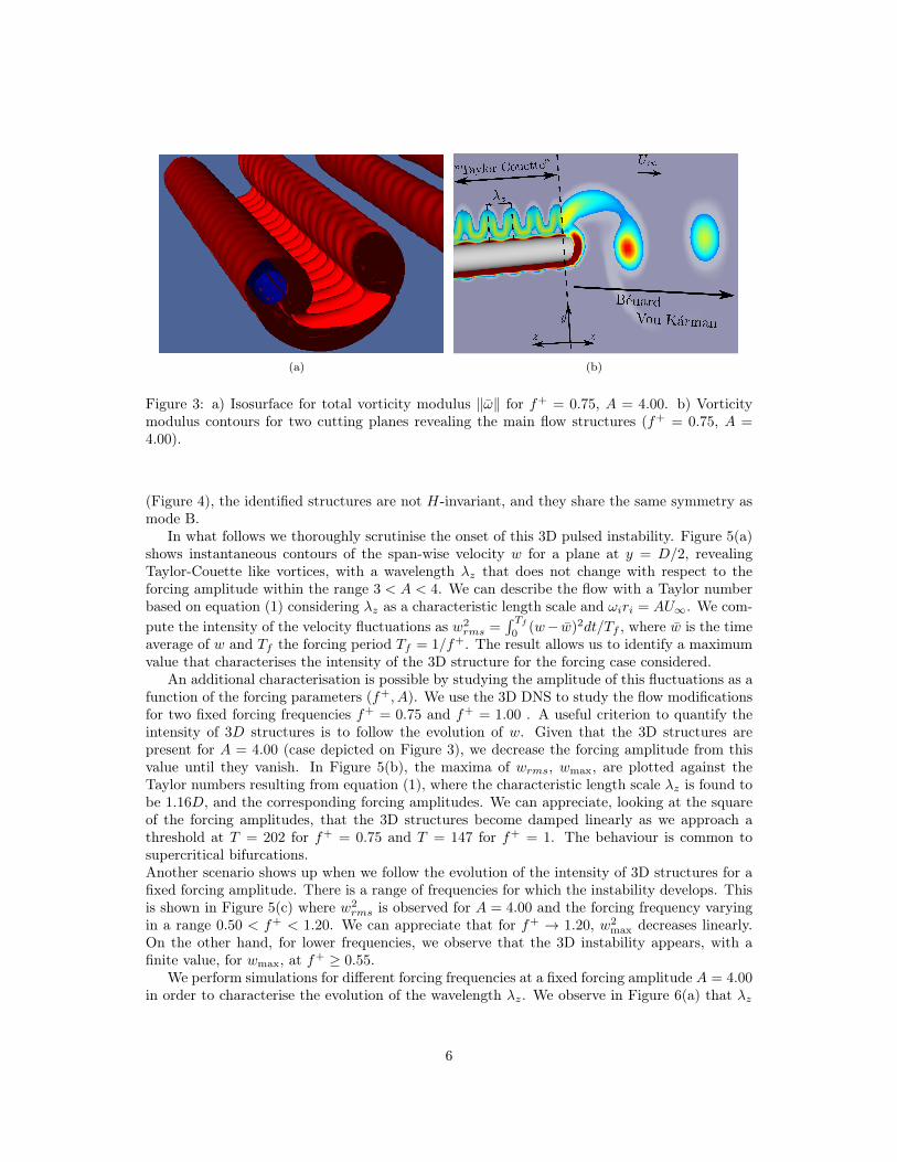
. Moreover, Figure 4shows the spatial distribution of !
x
along with !z
for f+
= 0.75, A = 4.00, which allows us toconsider the symmetry properties of the observed mode. The spatio-temporal symmetry, H , ofthe two-dimensional flow is defined as:
H!(x, t) = Ky
!(x, t+ T/2) = (�!x
,!y
,�!z
)(x,�y, t+ T/2) (4)
where Ky
is a spatial reflection. For an H-symmetric flow, from 4, the x-vorticity changes signwith t ! t+T/2 and y ! �y at any fixed (x, z). This is the case for mode A, whereas for modeB, the sign of x-vorticity does not change.
As studied by Blackburn et al. (2005), there are exactly three codimension-one bifurcationsfrom a two-dimensional time-periodic base state to three-dimensional flow that are observablewith variations in a single parameter. In this regard, Lo Jacono et al. (2010) showed thatoscillatory forcing at Re = 300 leads to the appearance of a different mode (mode D) whichhas the same symmetries of mode A. Considering the symmetries observed in the present case
5
(a) (b)
Figure 3: a) Isosurface for total vorticity modulus k!̄k for f+
= 0.75, A = 4.00. b) Vorticitymodulus contours for two cutting planes revealing the main flow structures (f+
= 0.75, A =
4.00).
(Figure 4), the identified structures are not H-invariant, and they share the same symmetry asmode B.
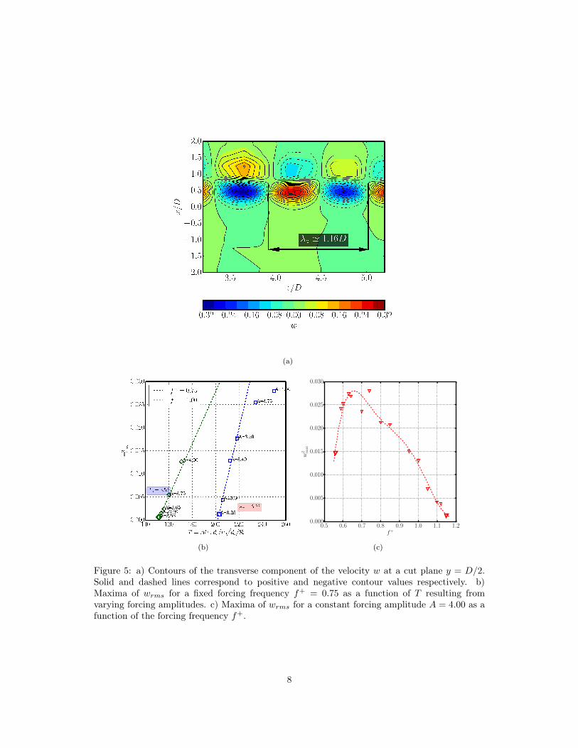
In what follows we thoroughly scrutinise the onset of this 3D pulsed instability. Figure 5(a)shows instantaneous contours of the span-wise velocity w for a plane at y = D/2, revealingTaylor-Couette like vortices, with a wavelength �
z
that does not change with respect to theforcing amplitude within the range 3 < A < 4. We can describe the flow with a Taylor numberbased on equation (1) considering �
z
as a characteristic length scale and !i
ri
= AU1. We com-pute the intensity of the velocity fluctuations as w2
rms
=
RTf
0
(w� w̄)2dt/Tf
, where w̄ is the timeaverage of w and T
f
the forcing period Tf
= 1/f+. The result allows us to identify a maximumvalue that characterises the intensity of the 3D structure for the forcing case considered.
An additional characterisation is possible by studying the amplitude of this fluctuations as afunction of the forcing parameters (f+, A). We use the 3D DNS to study the flow modificationsfor two fixed forcing frequencies f+
= 0.75 and f+
= 1.00 . A useful criterion to quantify theintensity of 3D structures is to follow the evolution of w. Given that the 3D structures arepresent for A = 4.00 (case depicted on Figure 3), we decrease the forcing amplitude from thisvalue until they vanish. In Figure 5(b), the maxima of w
rms
, wmax
, are plotted against theTaylor numbers resulting from equation (1), where the characteristic length scale �
z
is found tobe 1.16D, and the corresponding forcing amplitudes. We can appreciate, looking at the squareof the forcing amplitudes, that the 3D structures become damped linearly as we approach athreshold at T = 202 for f+
= 0.75 and T = 147 for f+
= 1. The behaviour is common tosupercritical bifurcations.Another scenario shows up when we follow the evolution of the intensity of 3D structures for afixed forcing amplitude. There is a range of frequencies for which the instability develops. Thisis shown in Figure 5(c) where w2
rms
is observed for A = 4.00 and the forcing frequency varyingin a range 0.50 < f+ < 1.20. We can appreciate that for f+ ! 1.20, w2
max
decreases linearly.On the other hand, for lower frequencies, we observe that the 3D instability appears, with afinite value, for w
max
, at f+ � 0.55.We perform simulations for different forcing frequencies at a fixed forcing amplitude A = 4.00
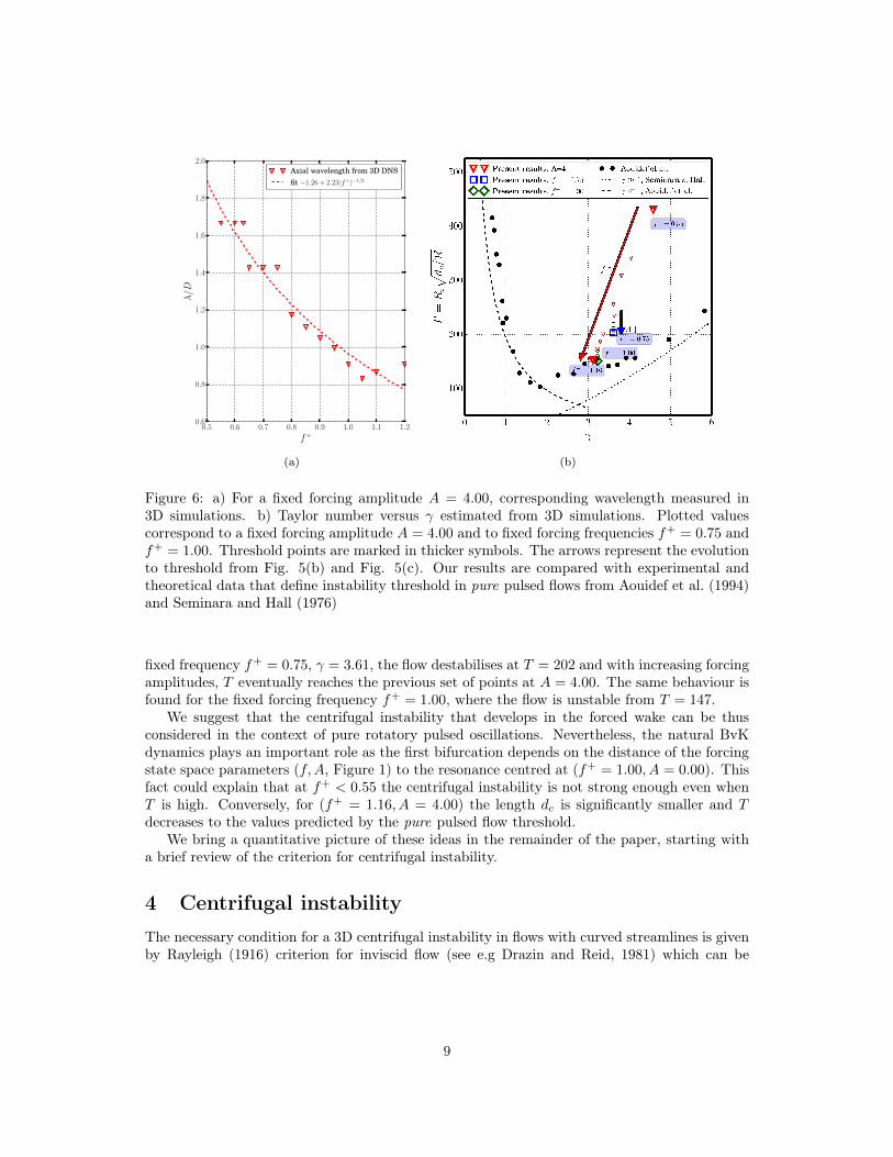
in order to characterise the evolution of the wavelength �z
. We observe in Figure 6(a) that �z
6
(a) (b)
Figure 4: For forcing parameters f+
= 0.75, A = 4.00. a) Isosurfaces for streamwise vorticity!x
: !x
= 3 (red), !x
= �3 (blue). The white isosurface represents spanwise vorticity !z
= 15
b) Top view for isosurfaces for streamwise and spanwise vorticity.
depends on f+ following a law / (f+
)
�1/2. If we assume that the “gap” size d is proportionalto �
z
, from the Taylor number definition in equation (1), where T depends on d3/2, then weexpect that high forcing frequencies produce decreasing Taylor numbers. This could explain thedamping of 3D fluctuations for higher frequencies in Figure 5(c). In addition, we observe thatthe wavelength �
z
is practically invariant with respect to the amplitude for a given frequency.In studies of pulsed centrifugal instabilities, Riley and Laurence (1976); Carmi and Tustani-
wskyj (1981); Aouidef et al. (1994) classified flow regimes based on a parameter � =
p!d2
c
/2⌫which is the ratio of a centrifugal region length d
c
to the Stokes layer thickness. In our exper-iment, � is limited to a range between 2 and 5, it does not depend on the forcing frequencyand d
c
⇠ � behaves with respect to f+ as described in Figure 6(a), where � decreases almostlinearly as (f+
)
�1/2.Even though the threshold for centrifugal instabilities determined in the Taylor-Couette
pulsed flow is not directly applicable for a configuration with crossflow, the transformation ofTaylor numbers based on the characteristic length d
c
allows an approach for our results. Thiscase presents similarity with the eccentric Taylor-Couette instability problem (see e.g. Leclercqet al. (2013); Shu et al. (2004); Siong (2006) and references therein). Indeed, in those problems,the axial wavelength of the critical perturbations is always of the same order of magnitude ofthe gap.
Figure 6(b) summarises the stability curves (�, T ) for centrifugal pulsed flow determined byAouidef et al. (1994); Seminara and Hall (1976) together with the values issued from our 3Dsimulations. Two analytical curves show the solution corresponding to low values of �, T
c
=
193.23��1 and high values of �, Tc
= 15.28�3/2. The curves are supported with experimentaldata from Aouidef et al. (1994). On the other hand, within these reference threshold frame,we plotted from our results T against � for a fixed forcing amplitude A = 4.00, and for fixedforcing frequencies f+
= 0.75 and f+
= 1.00 (the same data used to construct Figure 5). Weobserve that the points are contained in the unstable region defined by the analytical curves.For A = 4.00, the instability develops for 0.55 < f+ < 1.16. When f+
= 1.16, the critical point(� = 3.06, T = 152) is in very good agreement with the experimental results from pure pulsedflows. For decreasing frequencies, T increases almost linearly regarding the estimated � until forf+
= 0.55 the flow stabilises with respect to centrifugal disturbances (� = 4.4, T = 433). For a
7
(a)
(b)
0.5 0.6 0.7 0.8 0.9 1.0 1.1 1.2
f
+
0.000
0.005
0.010
0.015
0.020
0.025
0.030
w
2
max
(c)
Figure 5: a) Contours of the transverse component of the velocity w at a cut plane y = D/2.Solid and dashed lines correspond to positive and negative contour values respectively. b)Maxima of w
rms
for a fixed forcing frequency f+
= 0.75 as a function of T resulting fromvarying forcing amplitudes. c) Maxima of w
rms
for a constant forcing amplitude A = 4.00 as afunction of the forcing frequency f+.
8
0.5 0.6 0.7 0.8 0.9 1.0 1.1 1.2
f
+
0.6
0.8
1.0
1.2
1.4
1.6
1.8
2.0
�/D
Axial wavelength from 3D DNS
fit �1.26 + 2.23(f
+)
�1/2
(a) (b)
Figure 6: a) For a fixed forcing amplitude A = 4.00, corresponding wavelength measured in3D simulations. b) Taylor number versus � estimated from 3D simulations. Plotted valuescorrespond to a fixed forcing amplitude A = 4.00 and to fixed forcing frequencies f+
= 0.75 andf+
= 1.00. Threshold points are marked in thicker symbols. The arrows represent the evolutionto threshold from Fig. 5(b) and Fig. 5(c). Our results are compared with experimental andtheoretical data that define instability threshold in pure pulsed flows from Aouidef et al. (1994)and Seminara and Hall (1976)
fixed frequency f+
= 0.75, � = 3.61, the flow destabilises at T = 202 and with increasing forcingamplitudes, T eventually reaches the previous set of points at A = 4.00. The same behaviour isfound for the fixed forcing frequency f+
= 1.00, where the flow is unstable from T = 147.We suggest that the centrifugal instability that develops in the forced wake can be thus
considered in the context of pure rotatory pulsed oscillations. Nevertheless, the natural BvKdynamics plays an important role as the first bifurcation depends on the distance of the forcingstate space parameters (f,A, Figure 1) to the resonance centred at (f+
= 1.00, A = 0.00). Thisfact could explain that at f+ < 0.55 the centrifugal instability is not strong enough even whenT is high. Conversely, for (f+
= 1.16, A = 4.00) the length dc
is significantly smaller and Tdecreases to the values predicted by the pure pulsed flow threshold.
We bring a quantitative picture of these ideas in the remainder of the paper, starting witha brief review of the criterion for centrifugal instability.
4 Centrifugal instability
The necessary condition for a 3D centrifugal instability in flows with curved streamlines is givenby Rayleigh (1916) criterion for inviscid flow (see e.g Drazin and Reid, 1981) which can be
9
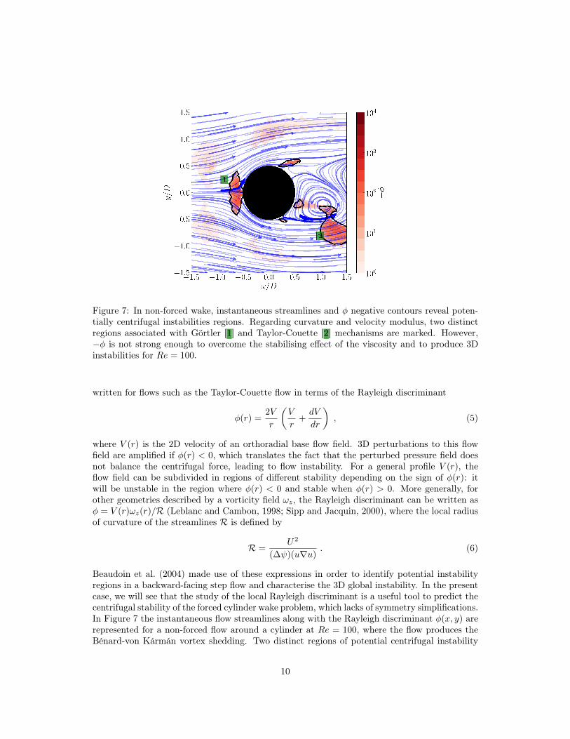
Figure 7: In non-forced wake, instantaneous streamlines and � negative contours reveal poten-tially centrifugal instabilities regions. Regarding curvature and velocity modulus, two distinctregions associated with Görtler [1] and Taylor-Couette [2] mechanisms are marked. However,�� is not strong enough to overcome the stabilising effect of the viscosity and to produce 3Dinstabilities for Re = 100.
written for flows such as the Taylor-Couette flow in terms of the Rayleigh discriminant
�(r) =2V
r
✓V
r+
dV
dr
◆, (5)
where V (r) is the 2D velocity of an orthoradial base flow field. 3D perturbations to this flowfield are amplified if �(r) < 0, which translates the fact that the perturbed pressure field doesnot balance the centrifugal force, leading to flow instability. For a general profile V (r), theflow field can be subdivided in regions of different stability depending on the sign of �(r): itwill be unstable in the region where �(r) < 0 and stable when �(r) > 0. More generally, forother geometries described by a vorticity field !
z
, the Rayleigh discriminant can be written as� = V (r)!
z
(r)/R (Leblanc and Cambon, 1998; Sipp and Jacquin, 2000), where the local radiusof curvature of the streamlines R is defined by
R =
U2
(� )(uru). (6)
Beaudoin et al. (2004) made use of these expressions in order to identify potential instabilityregions in a backward-facing step flow and characterise the 3D global instability. In the presentcase, we will see that the study of the local Rayleigh discriminant is a useful tool to predict thecentrifugal stability of the forced cylinder wake problem, which lacks of symmetry simplifications.In Figure 7 the instantaneous flow streamlines along with the Rayleigh discriminant �(x, y) arerepresented for a non-forced flow around a cylinder at Re = 100, where the flow produces theBénard-von Kármán vortex shedding. Two distinct regions of potential centrifugal instability
10
�1.0 �0.5 0.0 0.5 1.0
�1.0
�0.5
0.0
0.5
1.0
y/D
�1.0 �0.5 0.0 0.5 1.0
x/D
�1.0 �0.5 0.0 0.5 1.0
�1.5 �1.0 �0.5 0.0 0.5 1.0 1.5 2.0
�1.5
�1.0
�0.5
0.0
0.5
1.0
1.5
10
010
110
210
310
4
��
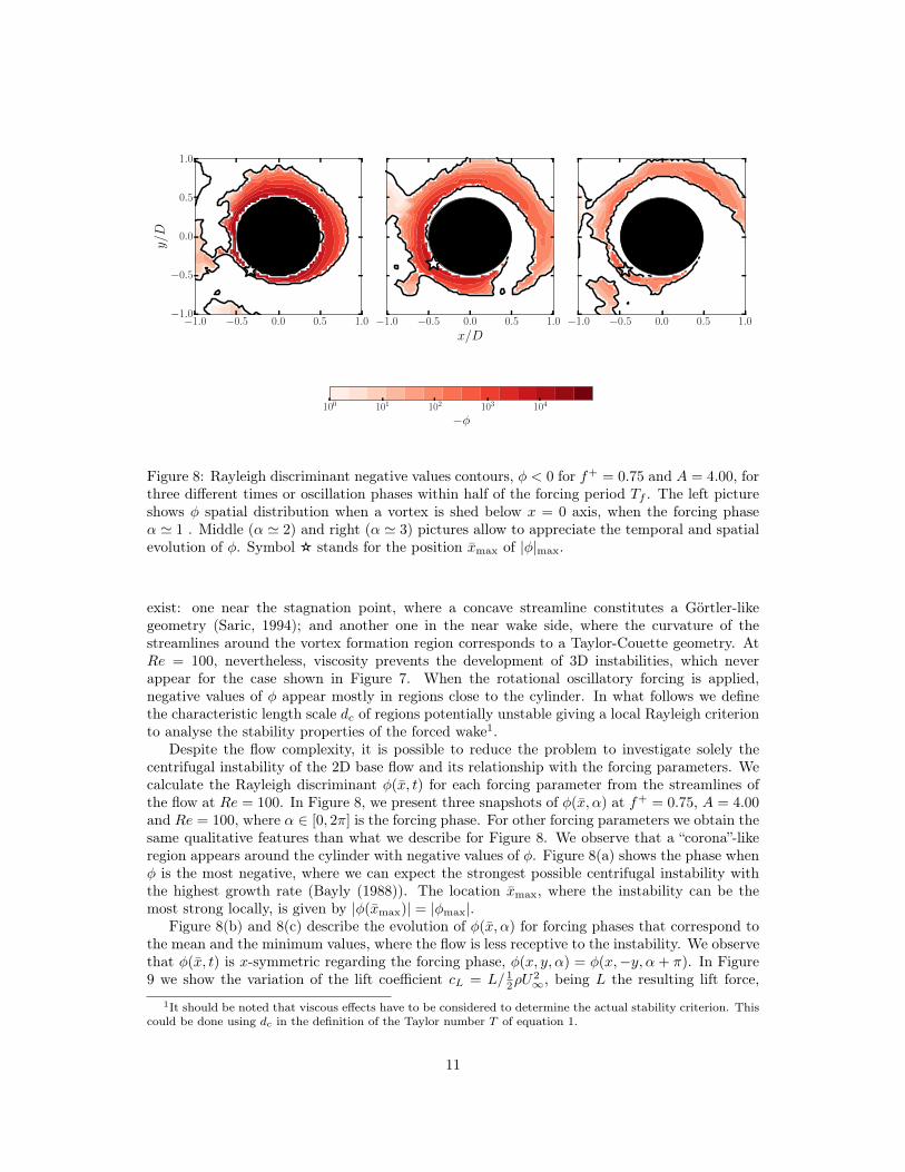
Figure 8: Rayleigh discriminant negative values contours, � < 0 for f+
= 0.75 and A = 4.00, forthree different times or oscillation phases within half of the forcing period T
f
. The left pictureshows � spatial distribution when a vortex is shed below x = 0 axis, when the forcing phase↵ ' 1 . Middle (↵ ' 2) and right (↵ ' 3) pictures allow to appreciate the temporal and spatialevolution of �. Symbol K stands for the position x̄
max
of |�|max
.
exist: one near the stagnation point, where a concave streamline constitutes a Görtler-likegeometry (Saric, 1994); and another one in the near wake side, where the curvature of thestreamlines around the vortex formation region corresponds to a Taylor-Couette geometry. AtRe = 100, nevertheless, viscosity prevents the development of 3D instabilities, which neverappear for the case shown in Figure 7. When the rotational oscillatory forcing is applied,negative values of � appear mostly in regions close to the cylinder. In what follows we definethe characteristic length scale d
c
of regions potentially unstable giving a local Rayleigh criterionto analyse the stability properties of the forced wake1.
Despite the flow complexity, it is possible to reduce the problem to investigate solely thecentrifugal instability of the 2D base flow and its relationship with the forcing parameters. Wecalculate the Rayleigh discriminant �(x̄, t) for each forcing parameter from the streamlines ofthe flow at Re = 100. In Figure 8, we present three snapshots of �(x̄,↵) at f+
= 0.75, A = 4.00and Re = 100, where ↵ 2 [0, 2⇡] is the forcing phase. For other forcing parameters we obtain thesame qualitative features than what we describe for Figure 8. We observe that a “corona”-likeregion appears around the cylinder with negative values of �. Figure 8(a) shows the phase when� is the most negative, where we can expect the strongest possible centrifugal instability withthe highest growth rate (Bayly (1988)). The location x̄
max
, where the instability can be themost strong locally, is given by |�(x̄
max
)| = |�max
|.Figure 8(b) and 8(c) describe the evolution of �(x̄,↵) for forcing phases that correspond to
the mean and the minimum values, where the flow is less receptive to the instability. We observethat �(x̄, t) is x-symmetric regarding the forcing phase, �(x, y,↵) = �(x,�y,↵ + ⇡). In Figure9 we show the variation of the lift coefficient c
L
= L/ 1
2
⇢U2
1, being L the resulting lift force,1It should be noted that viscous effects have to be considered to determine the actual stability criterion. This
could be done using dc in the definition of the Taylor number T of equation 1.
11
0 1 2 3 4 5 6
↵
10
1
10
2
10
3
10
4
10
5
|�| m
ax
|�|max
�1.0
�0.5
0.0
0.5
1.0
c
L
,R
c
L
R
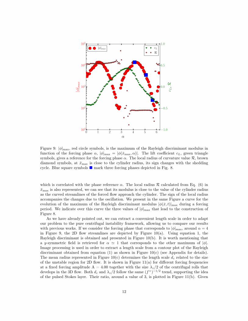
Figure 9: |�|max
, red circle symbols, is the maximum of the Rayleigh discriminant modulus infunction of the forcing phase ↵, |�|
max
= |�(x̄max
,↵)|. The lift coefficient cL
, green trianglesymbols, gives a reference for the forcing phase ↵. The local radius of curvature value R, browndiamond symbols, at x̄
max
is close to the cylinder radius, its sign changes with the sheddingcycle. Blue square symbols ⌅ mark three forcing phases depicted in Fig. 8.
which is correlated with the phase reference ↵. The local radius R calculated from Eq. (6) inx̄max
is also represented, we can see that its modulus is close to the value of the cylinder radiusas the curved streamlines of the forced flow approach the cylinder. The sign of the local radiusaccompanies the changes due to the oscillation. We present in the same Figure a curve for theevolution of the maximum of the Rayleigh discriminant modulus |�(x̄, t)|
max
during a forcingperiod. We indicate over this curve the three values of |�|
max
that lead to the construction ofFigure 8.
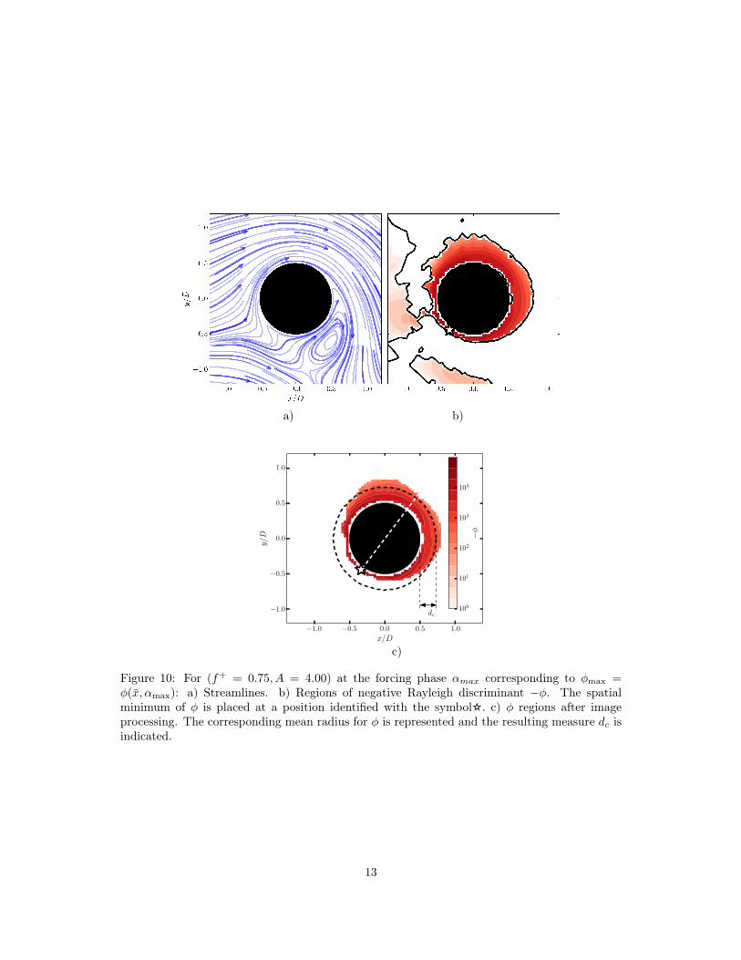
As we have already pointed out, we can extract a convenient length scale in order to adaptour problem to the pure centrifugal instability framework, allowing us to compare our resultswith previous works. If we consider the forcing phase that corresponds to |�|
max
, around ↵ = 4
in Figure 9, the 2D flow streamlines are depicted by Figure 10(a). Using equation 1, theRayleigh discriminant is obtained and presented in Figure 10(b). It is worth mentioning thata y-symmetric field is retrieved for ↵ ' 1 that corresponds to the other maximum of |�|.Image processing is used in order to extract a length scale from a contour plot of the Rayleighdiscriminant obtained from equation (1) as shown in Figure 10(c) (see Appendix for details).The mean radius represented in Figure 10(c) determines the length scale d
c
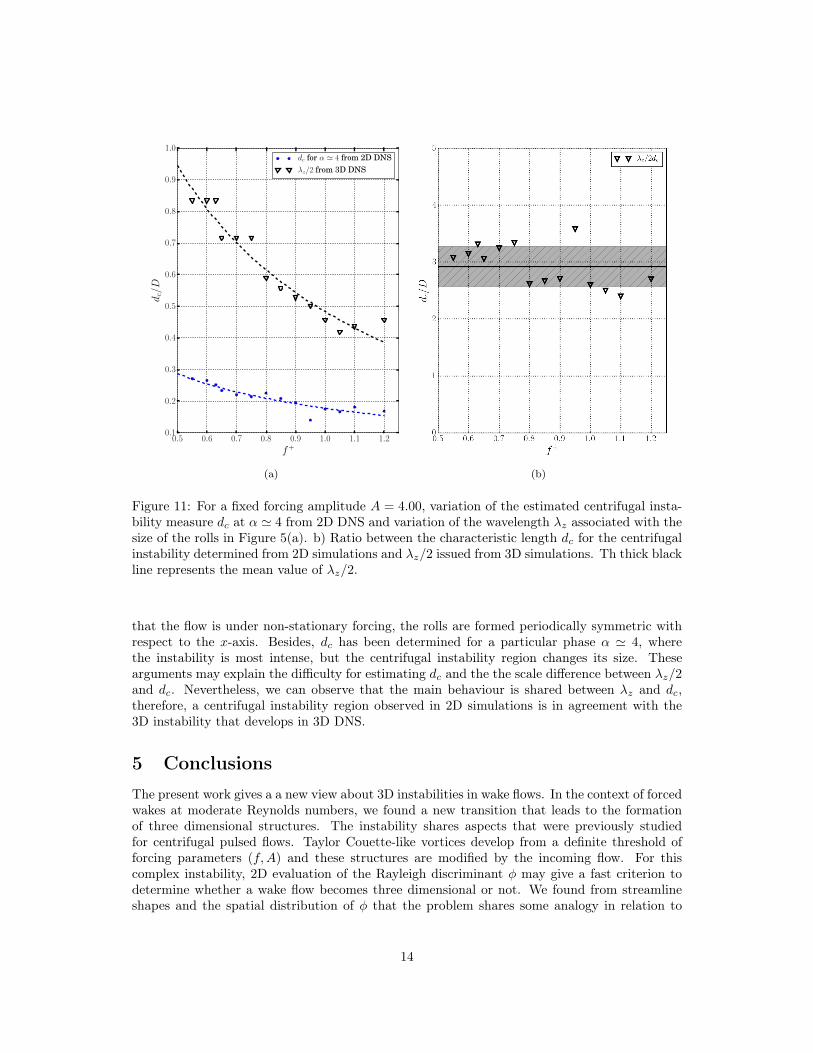
related to the sizeof the unstable region for 2D flow. It is shown in Figure 11(a) for different forcing frequenciesat a fixed forcing amplitude A = 4.00 together with the size �
z
/2 of the centrifugal rolls thatdevelops in the 3D flow. Both d
c
and �z
/2 follow the same (f+
)
�1/2 trend, supporting the ideaof the pulsed Stokes layer. Their ratio, around a value of 3, is plotted in Figure 11(b). Given
12
�1.0 �0.5 0.0 0.5 1.0
x/D
�1.0
�0.5
0.0
0.5
1.0
y/D
dc100
101
102
103
104
��
a) b)
c)
Figure 10: For (f+
= 0.75, A = 4.00) at the forcing phase ↵max
corresponding to �max
=
�(x̄,↵max
): a) Streamlines. b) Regions of negative Rayleigh discriminant ��. The spatialminimum of � is placed at a position identified with the symbolK. c) � regions after imageprocessing. The corresponding mean radius for � is represented and the resulting measure d
c
isindicated.
13
0.5 0.6 0.7 0.8 0.9 1.0 1.1 1.2
f
+
0.1
0.2
0.3
0.4
0.5
0.6
0.7
0.8
0.9
1.0
d
c
/D
d
c
for ↵ ' 4 from 2D DNS
�
z
/2 from 3D DNS
(a) (b)
Figure 11: For a fixed forcing amplitude A = 4.00, variation of the estimated centrifugal insta-bility measure d
c
at ↵ ' 4 from 2D DNS and variation of the wavelength �z
associated with thesize of the rolls in Figure 5(a). b) Ratio between the characteristic length d
c
for the centrifugalinstability determined from 2D simulations and �
z
/2 issued from 3D simulations. Th thick blackline represents the mean value of �
z
/2.
that the flow is under non-stationary forcing, the rolls are formed periodically symmetric withrespect to the x-axis. Besides, d
c
has been determined for a particular phase ↵ ' 4, wherethe instability is most intense, but the centrifugal instability region changes its size. Thesearguments may explain the difficulty for estimating d
c
and the the scale difference between �z
/2and d
c
. Nevertheless, we can observe that the main behaviour is shared between �z
and dc
,therefore, a centrifugal instability region observed in 2D simulations is in agreement with the3D instability that develops in 3D DNS.
5 Conclusions
The present work gives a a new view about 3D instabilities in wake flows. In the context of forcedwakes at moderate Reynolds numbers, we found a new transition that leads to the formationof three dimensional structures. The instability shares aspects that were previously studiedfor centrifugal pulsed flows. Taylor Couette-like vortices develop from a definite threshold offorcing parameters (f,A) and these structures are modified by the incoming flow. For thiscomplex instability, 2D evaluation of the Rayleigh discriminant � may give a fast criterion todetermine whether a wake flow becomes three dimensional or not. We found from streamlineshapes and the spatial distribution of � that the problem shares some analogy in relation to
14
eccentric Taylor Couette flows.As 2D forcing in wakes may indeed trigger 3D structures, this behaviour must be taken intoaccount in flow control schemes. Streamlines which result too much “bent“ by forcing in wakescan make evident strong negative values of the Rayleigh discriminant � and thus the possibilityof a centrifugal instability.On the other hand, this simple problem can offer an interesting benchmark to study instabilitiesand transition to turbulence from oscillatory rotation.
6 Appendix: Determination of the centrifugal instability
region length.
The choice of a characteristic length of the centrifugal instability region from the Rayleighdiscriminant scalar fields is not straightforward as we observe Fig. 8. we choose to select theforcing phase that corresponds to the minimum value of �, the most unstable state. Figure 10(b)presents such state but the � scalar field needs to be more clear in order to extract a length d
c
.Simple image processing functions, erosion and dilation, are applied successively to the scalarfield in order to obtain Fig 10(c), where a clear shape is noticed. We found that such shapehas an aspect that resembles an eccentric cylinder gap. Therefore, we choose as a characteristiclength the mean radius of this gap d
c
= 1/(2⇡)R2⇡
0
rd'�D/2, with r the shape radius varyingwith the angular coordinate '.
6.1 Convergence analysis for DNS
In order to ensure that the results do not depend on the size of the domain we chose, weperformed a convergence analysis for the 2D case. Given that the domain size of the referencestudy is L
x
⇥Ly
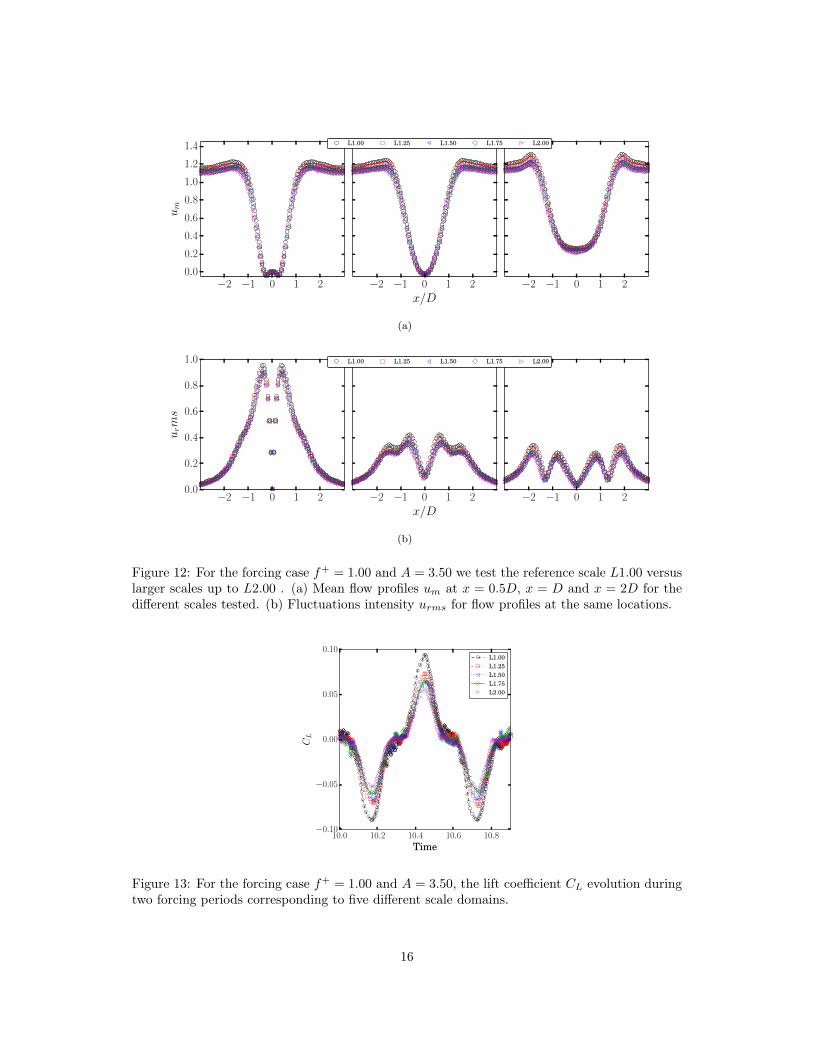
= 20D⇥10D, we label it as L1.00. As we selected larger domains which scale as[1.25; 1.50; 1.75; 2.00] the reference study length, we label them L1.25, L1.50, L1.75 and L2.00.For these scaling lengths, we plotted mean flow profiles for the streamwise component of thevelocity u
m
at three different x positions x = 0.5D, D, 2D in Fig. 12(a). Figure 12(b) presentsfor the same direction, fluctuations intensity u
rms
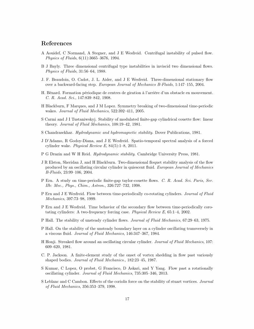
profiles for the same different x positions.We observe that changing the domain size does not modify the flow dynamics. Lift coefficientis also calculated for each case as it is presented in Fig.13. We also observe good agreementbetween the different scaling domains.
Data Accessibility
In order to reproduce all the calculations included in this paper, Gerris(Popinet, 2003) is avail-able free of charge under the Free Software GPL license and our code files can be downloadedfrom this URL.
Acknowledgment
We acknowledge support from the LIA PMF-FMF (Franco-Argentinian International AssociatedLaboratory in the Physics and Mechanics of Fluids), Argentina - France.
15
�2 �1 0 1 2
0.0
0.2
0.4
0.6
0.8
1.0
1.2
1.4
u
m
�2 �1 0 1 2
x/D
�2 �1 0 1 2
L1.00 L1.25 L1.50 L1.75 L2.00
(a)
�2 �1 0 1 2
0.0
0.2
0.4
0.6
0.8
1.0
u
r
ms
�2 �1 0 1 2
x/D
�2 �1 0 1 2
L1.00 L1.25 L1.50 L1.75 L2.00
(b)
Figure 12: For the forcing case f+
= 1.00 and A = 3.50 we test the reference scale L1.00 versuslarger scales up to L2.00 . (a) Mean flow profiles u
m
at x = 0.5D, x = D and x = 2D for thedifferent scales tested. (b) Fluctuations intensity u
rms
for flow profiles at the same locations.
10.0 10.2 10.4 10.6 10.8
Time
�0.10
�0.05
0.00
0.05
0.10
C
L
L1.00
L1.25
L1.50
L1.75
L2.00
Figure 13: For the forcing case f+
= 1.00 and A = 3.50, the lift coefficient CL
evolution duringtwo forcing periods corresponding to five different scale domains.
16
References
A Aouidef, C Normand, A Stegner, and J E Wesfreid. Centrifugal instability of pulsed flow.Physics of Fluids, 6(11):3665–3676, 1994.
B J Bayly. Three dimensional centrifugal type instabilities in inviscid two dimensional flows.Physics of Fluids, 31:56–64, 1988.
J. F. Beaudoin, O. Cadot, J. L. Aider, and J E Wesfreid. Three-dimensional stationary flowover a backward-facing step. European Journal of Mechanics B-Fluids, 1:147–155, 2004.
H. Bénard. Formation périodique de centres de giration à l’arrière d’un obstacle en mouvement.C. R. Acad. Sci., 147:839–842, 1908.
H Blackburn, F Marques, and J M Lopez. Symmetry breaking of two-dimensional time-periodicwakes. Journal of Fluid Mechanics, 522:392–411, 2005.
S Carmi and J I Tustaniwskyj. Stability of modulated finite-gap cylindrical couette flow: lineartheory. Journal of Fluid Mechanics, 108:19–42, 1981.
S Chandrasekhar. Hydrodynamic and hydromagnetic stability. Dover Publications, 1981.
J D’Adamo, R Godoy-Diana, and J E Wesfreid. Spatio-temporal spectral analysis of a forcedcylinder wake. Physical Review E, 84(5):1–8, 2011.
P G Drazin and W H Reid. Hydrodynamic stability. Cambridge University Press, 1981.
J R Elston, Sheridan J, and H Blackburn. Two-dimensional floquet stability analysis of the flowproduced by an oscillating circular cylinder in quiescent fluid. European Journal of MechanicsB-Fluids, 23:99–106, 2004.
P Ern. A study on time-periodic finite-gap taylor-couette flows. C. R. Acad. Sci. Paris, Ser.IIb: Mec., Phys., Chim., Astron., 326:727–732, 1998.
P Ern and J E Wesfreid. Flow between time-periodically co-rotating cylinders. Journal of FluidMechanics, 397:73–98, 1999.
P Ern and J E Wesfreid. Time behavior of the secondary flow between time-periodically coro-tating cylinders: A two-frequency forcing case. Physical Review E, 65:1–4, 2002.
P Hall. The stability of unsteady cylinder flows. Journal of Fluid Mechanics, 67:29–63, 1975.
P Hall. On the stability of the unsteady boundary layer on a cylinder oscillating transversely ina viscous fluid. Journal of Fluid Mechanics, 146:347–367, 1984.
H Honji. Streaked flow around an oscillating circular cylinder. Journal of Fluid Mechanics, 107:609–620, 1981.
C. P. Jackson. A finite-element study of the onset of vortex shedding in flow past variouslyshaped bodies. Journal of Fluid Mechanics., 182:23–45, 1987.
S Kumar, C Lopez, O probst, G Francisco, D Askari, and Y Yang. Flow past a rotationallyoscillating cylinder. Journal of Fluid Mechanics, 735:305–346, 2013.
S Leblanc and C Cambon. Effects of the coriolis force on the stability of stuart vortices. Journalof Fluid Mechanics, 356:353–379, 1998.
17
C Leclercq, B Pier, and J F Scott. Temporal stability of eccentric taylor-couette-poiseuille flow.Journal of Fluid Mechanics, 733:68–99, 2013.
D Lo Jacono, J Leontini, M Thompson, and Sheridan J. Modification of three-dimensionaltransition in the wake of a rotationally oscillating cylinder. Journal of Fluid Mechanics, 643:349–362, 2010.
S Popinet. Gerris: a tree-based adaptive solver for the incompressible euler equations in complexgeometries. Journal of Computational Physics, 190(2):572 – 600, 2003.
J O Pralits, F Giannetti, and L Brandt. Three-dimensional instability of the flow around arotating circular cylinder. Journal of Fluid Mechanics, 730:5–18, 2013.
M. Provansal, C. Mathis, and L. Boyer. Bénard-von Kármán instability: transient and forcedregimes. Journal of Fluid Mechanics., 182(-1):1–22, 1987.
J W S Rayleigh. On the dynamics of revolving fluids. Proceedings of the Royal Society ofLondon. Series A, Mathematical and Physical Sciences, 93:148–154, 1916.
P J Riley and R L Laurence. Linear stability of modulated circular couette flow. Journal ofFluid Mechanics, 75:625–646, 1976.
W Saric. Görtler vortices. Annual Review of Fluid Mechanics, 26:379–409, 1994.
G Seminara and P Hall. Centrifugal instability of a stokes layer: Linear theory. Proceedingsof the Royal Society of London. Series A, Mathematical and Physical Sciences, 350:299–316,1976.
C Shu, L Wang, Y T Chew, and N Zhao. Numerical study of eccentric couette-taylor flows andeffect of eccentricity on flow patterns. Theoretical and Computational Fluid Dynamics, 18:43–59, 2004.
L Shoa Siong. An experimental investigation of taylor couette flow between eccentric cylinders.Master’s thesis, National University of Singapore, 2006.
D Sipp and L Jacquin. A criterion of centrifugal instabilities in rotating systems. In Agnès Maureland Philippe Petitjeans, editors, Vortex Structure and Dynamics, volume 555 of Lecture Notesin Physics, pages 299–308. Springer Berlin Heidelberg, 2000.
S. Taneda. Visual observations of flow past a circular-cylinder performing a rotatory oscillation.Journal of the Physical Society of Japan, 45(3):1038–1043, 1978. ISSN 0031-9015.
M Tatsuno and P W Bearman. A visual study of the flow around an oscillating circular cylinderat low keulegan-carpenter numbers and low stokes numbers. Journal of Fluid Mechanics, 211:157.182, 1990.
B. Thiria and J. E. Wesfreid. Stability properties of forced wakes. Journal of Fluid Mechanics.,579:137–161, 2007.
B. Thiria, S. Goujon-Durand, and J. E. Wesfreid. Wake of a cylinder performing rotary oscilla-tions. Journal of Fluid Mechanics., 560:123–147, 2006.
T. von Kármán. Über den mechanismus des widerstandes, den ein bewegter körper in einerflüssigkeit erfährt. Nachr. Ges. Wissenschaft. Göttingen, pages 509–517, 1911.
18