Embed Size (px)
Citation preview
Futuremark Inc.
3DMark Vantage Whitepaper Revision 2
Product version: 1.0.0
Jyrki Korpi-Anttila, Tatu Aalto, Jaakko Haapasalo, Juha Sjöholm, Kimmo Pietilä, Antti Kerminen 5/19/2008
Contents 1 Purpose of this document ................................................................................................................................5
2 Aims ..................................................................................................................................................................5
3 Principles ..........................................................................................................................................................5
4 Test Mix ............................................................................................................................................................5
5 Rendering Engine ..............................................................................................................................................6
5.1 3D Engine architecture .............................................................................................................................6
5.2 Lighting model ..........................................................................................................................................6
5.2.1 High Dynamic Range .........................................................................................................................6
5.2.2 Surface shading and shader composition .........................................................................................7
5.2.3 Shadows ............................................................................................................................................7
5.3 Post-processing.........................................................................................................................................7
5.3.1 Bloom ................................................................................................................................................8
5.3.2 Streaks ..............................................................................................................................................8
5.3.3 Anamorphic flare ..............................................................................................................................8
5.3.4 Lens flare (ghosting) .........................................................................................................................8
5.3.5 Lenticular halo ..................................................................................................................................8
5.3.6 Depth-of-field ...................................................................................................................................8
5.3.7 Motion blur .......................................................................................................................................8
5.3.8 Depth fog ..........................................................................................................................................8
5.3.9 Volumetric fog ..................................................................................................................................9
5.3.10 Tone mapping ...................................................................................................................................9
5.4 GPU physics simulations ...........................................................................................................................9
5.5 Particle system rendering .........................................................................................................................9
5.6 Rendering options ....................................................................................................................................9
5.6.1 Screen resolution ..............................................................................................................................9
5.6.2 Multisample count ............................................................................................................................9
5.6.3 Texture filtering and Maximum anisotropy ......................................................................................9
5.6.4 Texture quality ..................................................................................................................................9
5.6.5 Shadow shader quality .................................................................................................................. 10
5.6.6 Shadow resolution quality ............................................................................................................. 10
5.6.7 Shader quality ................................................................................................................................ 10
5.6.8 Post-processing scale ..................................................................................................................... 10
5.6.9 Post-processing disable per effect................................................................................................. 10
6 Graphics Tests ................................................................................................................................................ 10
6.1 Common features .................................................................................................................................. 10
6.2 Jane Nash (Graphics Test 1) ................................................................................................................... 10
6.3 Calico (Graphics Test 2) ......................................................................................................................... 11
6.4 Graphics Test Results ............................................................................................................................. 11
7 CPU Tests ....................................................................................................................................................... 11
7.1 Rendering .............................................................................................................................................. 11
7.2 AI Test (CPU Test 1) ............................................................................................................................... 11
7.2.1 Content .......................................................................................................................................... 11
7.2.2 Load ............................................................................................................................................... 11
7.2.3 Parallelization ................................................................................................................................ 12
7.2.4 Result ............................................................................................................................................. 12
7.3 Physics Test (CPU Test 2) ....................................................................................................................... 12
7.3.1 Content .......................................................................................................................................... 12
7.3.2 Load and parallelization................................................................................................................. 13
7.3.3 Result ............................................................................................................................................. 13
8 Feature Tests ................................................................................................................................................. 14
8.1 Texture fill rate test ............................................................................................................................... 14
8.2 Color fill rate test ................................................................................................................................... 14
8.3 POM Shader test .................................................................................................................................... 14
8.4 Cloth simulation test ............................................................................................................................. 14
8.5 Particle simulation test .......................................................................................................................... 14
8.6 Shader math test ................................................................................................................................... 14
9 Presets ........................................................................................................................................................... 15
10 Scoring ....................................................................................................................................................... 15
10.1 Graphics test scoring ............................................................................................................................. 15
10.2 CPU test scoring ..................................................................................................................................... 16
10.3 3DMark score ........................................................................................................................................ 16

11 Product Editions ........................................................................................................................................ 16
1 Purpose of this document This whitepaper represents the state of the last product release as of document date.
2 Aims 3DMark Vantage is a gamers’ benchmark for the DX10 platform. Its primary purpose is to help gamers evaluate
their system performance for gaming use, and through online services relate the tested system to other
available hardware. This should provide true value to gamers by enabling them to make better purchasing
decisions, and to compete against each other in system performance.
In order to meet its primary purpose, the benchmark should provide results that remain relevant for at least
one year after launch, and optimally two or more. This means anticipating both upcoming hardware
capabilities and performance-related trends in future games. A key benefit of the Benchmark Development
Program (BDP) is mitigating uncertainty related to upcoming hardware. On game software performance trends,
we rely on our own research and judgment, and our partners both inside and outside the BDP.
3 Principles There are three guiding principles we follow in determining the benchmark test mix, architecture, content and
scoring. These principles help the benchmark to serve its primary purpose:
Prefer game-like content,
Represent technology fairly and accurately, and
Exercise technology with a view to the future.
4 Test Mix The Vista PC is a target platform with huge performance disparities in several hardware areas. 3DMark Vantage
focuses on the two areas most critical to gaming performance: the CPU and the GPU. With the emergence of
multi-package and multi-core configurations on both the CPU and GPU side, the performance scale of these
areas has widened, and the visual and game-play effects made possible by these configurations are accordingly
wide-ranging. This makes covering the entire spectrum of 3D gaming a difficult task. 3DMark Vantage solves
this problem in three ways:
1. Isolate GPU and CPU performance benchmarking into separate tests,
2. Cover several visual and game-play effects and techniques in four different tests, and
3. Introduce visual quality presets to scale the graphics test load up through the highest-end hardware.
To this end, 3DMark Vantage has two GPU tests, each with a different emphasis on various visual techniques,
and two CPU tests, which cover the two most common CPU-side tasks: Physics Simulation and AI. It also has
four visual quality presets (Entry, Performance, High, and Extreme) available in the Advanced and Professional
versions, which increase the graphics load successively for even more visual quality. Each preset will produce a
separate, official 3DMark Score, tagged with the preset in question.
5 Rendering Engine The 3DMark Vantage Rendering Engine (“Engine” for short) supports multiple dynamic lights in a single pass,
complex character rigs, GPU-simulated content and complex, custom lighting models for surface materials and
light-surface interaction.
5.1 3D Engine architecture Our engine performs the following rendering passes and sub-passes per frame:
1. GPU simulation update loop
a. Rendering of simulation inputs (depth views)
2. Shadow map generation
3. Pre-depth for appropriate materials (speed optimization)
4. Opaque illumination
a. Possible hierarchical rendering steps (reflection, refraction)
5. Translucent illumination
6. Post-processing
a. Possible custom scene rendering passes
GPU simulations are performed as fixed-step loops. Texture and vertex simulation steps are repeated until the
simulations reach parity with wall-clock time. Some simulations use depth views rendered from the scene as
collision or pressure inputs.
We generate all required shadow maps before the main scene rendering. The main scene render pass consists
of steps 3, 4 and 5. The pre-depth pass is performed for selected materials to reduce overdraw of materials
with heavy pixel shaders in the main opaque pass.
The translucent illumination pass supports soft clipping, utilizing the results of the opaque illumination pass.
We perform a CopyResource() call (or ResolveSubresource() when MSAA is enabled) on the depth buffer to
make it available for particle rendering.
The post-processing step takes the scene render output, and applies a variety of image-space filters and
effects. Some post-processing steps may require special scene rendering passes, like the velocity pass needed
by the motion blur effect.
We perform automatic run-time instancing of objects in the frustum based on pre-calculated model
comparison. Frustum culling is performed per item.
5.2 Lighting model
5.2.1 High Dynamic Range
Our Engine renders everything in high dynamic range (HDR), using 16-bit-per-component floating-point render
targets. The HDR render target is passed along to post-processing, and finally tone-mapping for display.
Cube map textures are stored in HDR format, but most standard 2D color textures are not. They are instead
stored using 8 bits / channel in linear space (conversion from the sRGB space used by most image editing
software is done as part of our asset creation pipeline).
5.2.2 Surface shading and shader composition
Our Engine composes shaders from three types of parts: material shaders, light shaders and transformation
shaders. Material shaders describe how the surface reflects and emits light. Light shaders describe how light
from light sources reaches the material surface. Transformation shaders perform vertex transformation.
The surface and light shaders are stored in HLSL fragments. When rendering a surface that is affected by one or
more lights, the Engine first combines the appropriate surface shader fragment with all necessary light shader
snippets using text pre-processing, and then compiles the shader. For performance reasons, needed shader
combinations are pre-generated and cached for fast access in real-time, as part of a warm-up phase before test
rendering.
The combined shader loops over all the affecting lights, and calls the surface shading function to apply the light
intensity from a certain direction for each light. Multiple lights of different kinds can be handled by a combined
shader in a single pass. The light parameters are packed into shader resource buffers by the Engine.
5.2.3 Shadows
We implemented Variance Shadow Maps and PCF-filtered cascaded shadow maps. The PCF shadows have
penumbra size estimation and an option to adjust shadow shader quality in terms of sample tap count. We are
not using penumbra dithering. The VSM uses light bleeding reduction.
5.3 Post-processing Post-processing effects are performed in a separate step after main scene rendering, but may trigger recursive
rendering passes, as in the case of motion blur, which requires a special velocity render of the scene, apart
from the main color output.
We support a set of per-camera animated post-processing effects, including the following:
Bloom
Streaks
Anamorphic flare
Lens flare (ghosting)
Lenticular halo
Depth-of-field
Motion blur
Depth fog
Film grain noise
Volumetric fog
Tone-mapping w/ gamma correction and vignette
5.3.1 Bloom
To create the bloom effect, we render the scene to a texture, and then halve it progressively. Each down-sized
frame is then blurred using a Gaussian filter. The final effect is the result of a weighted sum of these blurred
frames, and is blended back onto the original texture. This tends to bleed bright areas of the picture into their
surroundings. An artist-controllable blurring threshold excludes low intensities from the blurring pass, helping
maintain image sharpness in moderately lit areas of the screen.
5.3.2 Streaks
To create the streak effect, we again progressively halve the original scene image down to a smaller resolution,
and then apply a six line convolution with 32 samples per line to the small resolution image. The convolution
result is blended back to the original image. Streaking is a camera artifact, caused by the hexagonal aperture
blade arrangement in the camera objective.
5.3.3 Anamorphic flare
The flare is implemented using two horizontal streaks with colorization.
5.3.4 Lens flare (ghosting)
We create the lens flare effect by scaling the input image around the center using several different scaling
factors, including negative ones. A vignette effect is applied to the input image to avoid hard edges at image
borders. All scale factors are sampled and composited in a single pass by a single shader.
5.3.5 Lenticular halo
The halo effect is created in three stages:
1. Reduce the original image to one quarter horizontal and vertical resolution
2. Apply a spherical filter
a. 32 point samples spread along the circumference of a circle
b. The samples are offset randomly towards or away from the center
c. The samples are colorized based on distance to center to create a spectrum separation effect
d. The kernel is rotated pseudo-randomly per pixel
3. Blur the filtered texture using a separable Gaussian kernel to reduce halo graininess caused by the
limited number of samples
5.3.6 Depth-of-field
We first combine the scene color and focus information (calculated from scene depth) into an RGBA16 texture.
Then we take a scaled copy of the result and blur it using a Gaussian kernel. The final scene with DOF is then
mixed from these two images.
5.3.7 Motion blur
We first render the view space velocity information of the scene into an RGBA16 texture. Using the velocity
information, we then blur the original rendered scene towards the direction of movement.
5.3.8 Depth fog
We render depth fog as a post processing effect by simply adding depth dependant color over the scene.
5.3.9 Volumetric fog
The volumetric fog samples fog density and color functions and shadow maps along the viewing ray,
accumulating color and alpha. Sampling positions are jittered to trade off aliasing for noise. To create a big
enough fog that is still detailed, we use a density function that non-linearly combines many samples from
volumetric textures at different scales. This is also helpful in animating the fog. Sampling shadow maps yields
volumetric shadows. The fog is a very expensive effect due to the high complexity of the calculations and the
large number of samples required to keep visual quality acceptable. Therefore we render fog at a 4x4 times
reduced resolution. Intersection with the fog bounding volume, which is a cylinder, is calculated analytically in
the pixel shader.
5.3.10 Tone mapping
We use a simple tone mapping operator with animated exposure and gamma correction, and an added
vignette effect that can be used to colorize image corners.
5.4 GPU physics simulations The Engine supports both texture simulations and vertex simulations. In texture simulations, one or more
simulation state buffers are rendered back and forth, using a full-screen quad to cover the entire output
texture. The calculations are done per pixel using pixel shaders.
Vertex simulations use stream-out to cycle vertex buffers through the simulation pass. We do not use draw
auto or auto offset, because in our case we can keep the number of simulated vertices up to date on the CPU
side. Draw auto is an interesting future research direction, which might be useful in for example hierarchical
particle effects.
5.5 Particle system rendering The engine renders particles using soft clipping. The geometry shader is used to expand particle points into
billboards.
5.6 Rendering options Our engine supports the following options.
5.6.1 Screen resolution
We support all Direct3D-supported target resolutions.
5.6.2 Multisample count
We support all available MSAA sample counts for the chosen render target.
5.6.3 Texture filtering and Maximum anisotropy
We support optimal and anisotropic texture filtering.
5.6.4 Texture quality
This is a content-related option that controls source texture resolution as specified in each test scene. Lower
settings indicate lower texture resolutions.
5.6.5 Shadow shader quality
The shadow shader quality affects the number of shadow map samples taken in the PCF shadows.
5.6.6 Shadow resolution quality
The shadow resolution quality affects shadow map size.
5.6.7 Shader quality
The shader quality affects the used techniques and their quality in various shaders.
5.6.8 Post-processing scale
The scale of post-processing effects relative to screen resolution.
5.6.9 Post-processing disable per effect
We support selectively disabling each post-processing effect listed in section 5.3, except for the tone-mapping
operator which is required for HDR rendering.
6 Graphics Tests There are two graphics tests in 3DMark Vantage: Jane Nash (Graphics Test 1) and Calico (Graphics Test 2). The
tests use the same rendering engine, and share many features. Each test also has its own emphasis on specific
techniques.
6.1 Common features Both graphics tests use the same post-processing effects, outlined in section 5.3. Both graphics tests include a
fluid surface simulation implemented as a texture simulation. Both graphics tests include GPU-simulated
particle systems. The particle systems are implemented as GPU vertex simulations with simple Verlet
integration, gravity and air resistance.
6.2 Jane Nash (Graphics Test 1) The Jane Nash test scene represents a large indoor game scene with complex character rigs, physical GPU
simulations, multiple dynamic lights, and complex surface lighting models. It uses several hierarchical rendering
steps, including for water reflection and refraction, and physics simulation collision map rendering. The
following features are specific to this scene:
Lots of static objects
Lots of complex dynamic skinned objects
Cascaded shadow maps using PCF filtering
Very few instanced objects
No ray-marching (volumetric) effects
Cloth simulation
Anisotropic materials (math-heavy)
Caustics
Hierarchical rendering passes to render water reflection and refraction
6.3 Calico (Graphics Test 2) The Calico test scene represents a vast space scene with lots of moving but rigid objects and special content
like the planet and asteroid belt. The following features are specific to this scene:
Almost entirely consists of moving objects
No skinned objects
Variance shadow mapping shadows
Lots of instanced objects
Local and global ray-tracing effects (Parallax Occlusion Mapping, True Impostors and volumetric fog)
6.4 Graphics Test Results Graphics test performance is measured in frames per second (fps). The fps result is calculated by counting the
number of frames rendered during the test, and dividing by the time it took to run the test. The tests are
rendered in real-time.
7 CPU Tests
7.1 Rendering The CPU tests need to be visualized to validate a realistic, game-like scenario, and to provide the end user with
something interesting to watch while the test is executing. Both CPU tests use the same graphics engine to
visualize the game simulation as is used in the graphics tests.
In order to minimize GPU impact on the CPU score, the graphics workload, and especially the GPU workload is
kept to a minimum during the CPU test using the following means:
1. No post-processing effects are used, except for tone-mapping, which is required by the HDR-only
renderer.
2. No complex shaders are used.
3. No shadows are used.
4. Simplified geometry is used in the models.
5. The world outside the camera view is not modeled.
7.2 AI Test (CPU Test 1)
7.2.1 Content
The world of the AI test consists of a canyon that contains an airplane race course. The race course winds
through several gates that the planes must navigate in order. The air is crowded with planes competing for
advantageous routes.
7.2.2 Load
The significant computation in the AI test is composed of 3D path-finding for the planes. The path-finding
algorithm has three main characteristics:
1. It follows the gates in order
2. It approximates a physical flight model for a fixed-wing aircraft
3. It avoids collision with other planes
We perform a stochastic search of the space of all allowed paths for each plane. A special generator function
generates several random candidates according to a physically-based flight model for each path request. A
fitness function is used to select the best candidate as the path that will be used by the plane. The fitness
function takes into account factors such as ground proximity, and the proximity of other planes.
The stochastic method of generating lots of candidates, and then discarding most of them, requires a lot of
computation power. Despite that, it has several desirable qualities:
1. It degrades nicely: if there is a computation time limit, fewer candidates will be generated and tested,
and the result will typically look less intelligent, but there will always be a valid result available.
2. It has built-in randomization: the resulting airplane behavior will incorporate a pleasing random
variation among several intelligent-looking choices.
3. It is modular: the generator and fitness functions can vary independently. We could in theory use the
same ground-avoiding fitness function coupled with a generator function for hot air balloons or
rockets.
When hard guarantees about the path quality are not required (planes are allowed to crash if the search does
not produce a suitable non-crashing path in time), as long as most paths are relatively good, our algorithm is a
reasonable choice for 3D path-finding.
7.2.3 Parallelization
We use a thread pool with one thread per core. Available work is dispatched to the first available thread.
7.2.4 Result
The AI test performance is measured in operations per second (ops). The operation count is equal to the
number of 3D paths that were calculated for the airplanes during the test. The operation count is divided by
the test run time, yielding the ops result.
7.3 Physics Test (CPU Test 2) The physics test utilizes the AGEIA PhysX library to simulate a complex game world with large amounts of
physical content. The PhysX library also allows for an AGEIA physics accelerator (physics processing unit, PPU)
to be used, if one is installed.
The default settings will utilize the AGEIA PPU if available to simulate any or all parts of the physics content, as
deemed necessary. The utilization of the AGEIA PPU can be switched off and the result will still be approved as
a default result. GPU physics performance is not a part of this test as GPU physics capabilities are tested in GT1
and GT2.
7.3.1 Content
The world of the physics test consists of a large number of airplanes, all trying to fly through a set of air-race
gates at the same time. This results in a large number of collisions and breakages. The planes are composed of
12 rigid body pieces, held together by 11 breakable joints. Plane break-up on collision is unscripted, and driven
entirely by the physics simulation. The planes are propelled through the air by a set of simulated forces that
roughly approximate the combination of propulsion and lift.
The planes trail colored smoke, which is simulated using a fluid simulation system available in PhysX. The
smoke slowly dissipates over time.
There are two kinds of air race gates in the game world: donut-shaped floating gates and gates composed of
two tapered poles. The floating gates represent tough pressurized cloth, and the pole gates represent an
elastic, foamy substance. Both gate types are physically simulated using cloth and soft-body simulations
available in PhysX.
7.3.2 Load and parallelization
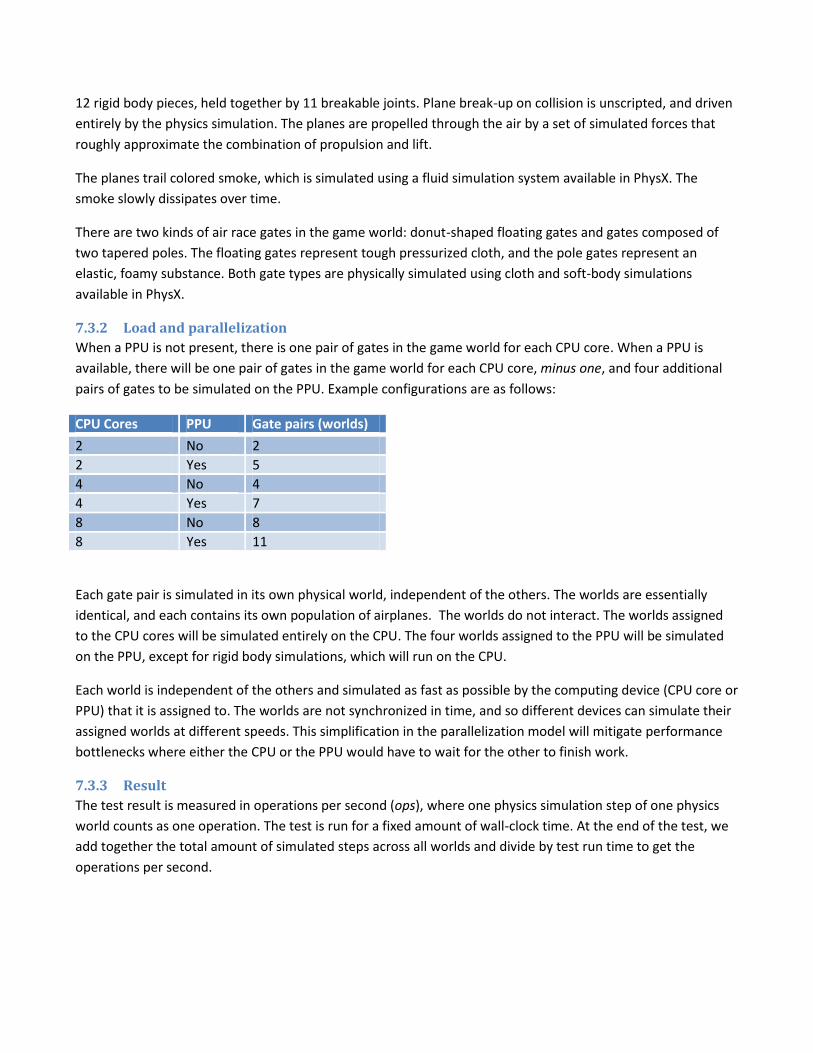
When a PPU is not present, there is one pair of gates in the game world for each CPU core. When a PPU is
available, there will be one pair of gates in the game world for each CPU core, minus one, and four additional
pairs of gates to be simulated on the PPU. Example configurations are as follows:
CPU Cores PPU Gate pairs (worlds)
2 No 2
2 Yes 5
4 No 4
4 Yes 7
8 No 8
8 Yes 11
Each gate pair is simulated in its own physical world, independent of the others. The worlds are essentially
identical, and each contains its own population of airplanes. The worlds do not interact. The worlds assigned
to the CPU cores will be simulated entirely on the CPU. The four worlds assigned to the PPU will be simulated
on the PPU, except for rigid body simulations, which will run on the CPU.
Each world is independent of the others and simulated as fast as possible by the computing device (CPU core or
PPU) that it is assigned to. The worlds are not synchronized in time, and so different devices can simulate their
assigned worlds at different speeds. This simplification in the parallelization model will mitigate performance
bottlenecks where either the CPU or the PPU would have to wait for the other to finish work.
7.3.3 Result
The test result is measured in operations per second (ops), where one physics simulation step of one physics
world counts as one operation. The test is run for a fixed amount of wall-clock time. At the end of the test, we
add together the total amount of simulated steps across all worlds and divide by test run time to get the
operations per second.
8 Feature Tests There are six feature tests in 3DMark Vantage. The feature tests are available in the Advanced and Professional
versions.
8.1 Texture fill rate test The test draws frames by filling the screen rectangle with values read from a tiny texture using multiple texture
coordinates. The texture coordinates are rotated and scaled between each frame.
8.2 Color fill rate test The test draws frames by filling the screen rectangle multiple times. The color and alpha of each corner of the
screen is animated. The pixel shader is pass-through. The interpolated color is written directly to the target
using alpha blending. The render target format is R16G16B16A16.
8.3 POM Shader test The POM shader test features a single quad shaded using the Parallax Occlusion Mapping technique. A 4k by 4k
height map representing a hilly landscape is mapped on the quad and rendered with 4 point lights and 3
directional lights in a single pass, using POM self-shadowing for each light.
8.4 Cloth simulation test The test renders twelwe waving flags that are simulated on the GPU. The computation is done in vertex and
geometry shaders and results are outputted using stream out. Each flag is modeled as a grid of vertices. Each
vertex is connected to its 8 neighbours with springs. Animated wind and gravity affects the behavior of each
flag.
8.5 Particle simulation test The test renders GPU simulated particles, which reveal an invisible shape by colliding to its surface. There are
hundreds of thousands of particles alive in the scene.
8.6 Shader math test The shader math test features multiple octaves of Perlin noise evaluated in the pixel shader. Each color channel
has its own noise function for added computation load.
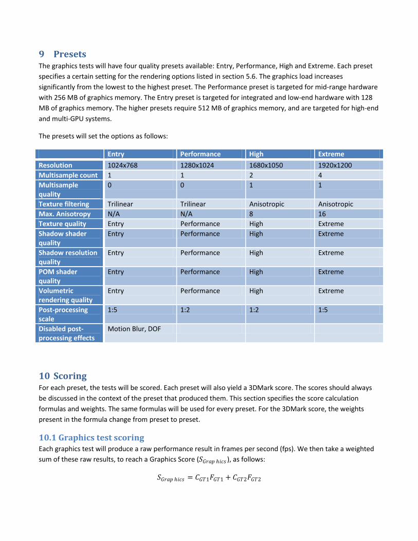
9 Presets The graphics tests will have four quality presets available: Entry, Performance, High and Extreme. Each preset
specifies a certain setting for the rendering options listed in section 5.6. The graphics load increases
significantly from the lowest to the highest preset. The Performance preset is targeted for mid-range hardware
with 256 MB of graphics memory. The Entry preset is targeted for integrated and low-end hardware with 128
MB of graphics memory. The higher presets require 512 MB of graphics memory, and are targeted for high-end
and multi-GPU systems.
The presets will set the options as follows:
Entry Performance High Extreme
Resolution 1024x768 1280x1024 1680x1050 1920x1200
Multisample count 1 1 2 4
Multisample quality
0 0 1 1
Texture filtering Trilinear Trilinear Anisotropic Anisotropic
Max. Anisotropy N/A N/A 8 16
Texture quality Entry Performance High Extreme
Shadow shader quality
Entry Performance High Extreme
Shadow resolution quality
Entry Performance High Extreme
POM shader quality
Entry Performance High Extreme
Volumetric rendering quality
Entry Performance High Extreme
Post-processing scale
1:5 1:2 1:2 1:5
Disabled post-processing effects
Motion Blur, DOF
10 Scoring For each preset, the tests will be scored. Each preset will also yield a 3DMark score. The scores should always
be discussed in the context of the preset that produced them. This section specifies the score calculation
formulas and weights. The same formulas will be used for every preset. For the 3DMark score, the weights
present in the formula change from preset to preset.
10.1 Graphics test scoring Each graphics test will produce a raw performance result in frames per second (fps). We then take a weighted
sum of these raw results, to reach a Graphics Score (𝑆𝐺𝑟𝑎𝑝 ℎ𝑖𝑐𝑠 ), as follows:
𝑆𝐺𝑟𝑎𝑝 ℎ𝑖𝑐𝑠 = 𝐶𝐺𝑇1𝐹𝐺𝑇1 + 𝐶𝐺𝑇2𝐹𝐺𝑇2
Where 𝐶𝐺𝑇1 is the scaling constant and 𝐹𝐺𝑇1 is the fps result for Graphics Test 1, and 𝐶𝐺𝑇1 is the scaling
constant and 𝐹𝐺𝑇2 is the fps result for Graphics Test 2. The constant scaling is done to bring the score in line
with traditional 3DMark score levels at the time of launch.
The Graphics score will be calculated using identical weights for each preset. Thus, it will remain comparable
across all presets, and even when using custom settings.
10.2 CPU test scoring Each CPU test will produce a raw performance result in operations per second (ops). We then take a weighted
sum of these raw results, to reach a CPU Score (𝑆𝐶𝑃𝑈 ), as follows:
𝑆𝐶𝑃𝑈 = 𝐶𝐶𝑃𝑈1𝑂𝐶𝑃𝑈1 + 𝐶𝐶𝑃𝑈2𝑂𝐶𝑃𝑈2
Where 𝐶𝐶𝑃𝑈1 is the scaling constant and 𝑂𝐶𝑃𝑈1 is the ops result for CPU Test 1, and 𝐶𝐶𝑃𝑈1 is the scaling
constant and 𝑂𝐶𝑃𝑈2 is the ops result for CPU Test 2. As with the graphics tests, the scaling factor 𝐶𝐶𝑃𝑈 is used
to bring the overall score into a traditional range.
The CPU score will be calculated using identical weights for each preset. Thus, it will remain comparable across
all presets, and even when using custom settings.
10.3 3DMark score The 3DMark Score (𝑆3𝐷𝑀𝑎𝑟𝑘 ) for each preset in 3DMark Vantage is formed from the GPU score and the CPU
score using a weighted harmonic mean, as follows:
𝑆3𝐷𝑀𝑎𝑟𝑘 =𝑊𝐺𝑟𝑎𝑝ℎ𝑖𝑐𝑠 +𝑊𝐶𝑃𝑈
𝑊𝐺𝑟𝑎𝑝 ℎ𝑖𝑐𝑠
𝑆𝐺𝑟𝑎𝑝 ℎ𝑖𝑐𝑠+𝑊𝐶𝑃𝑈𝑆𝐶𝑃𝑈
Where 𝑊𝐺𝑟𝑎𝑝 ℎ𝑖𝑐𝑠 is the Graphics score weight for the preset, and 𝑊𝐶𝑃𝑈 is the CPU score weight for the preset.
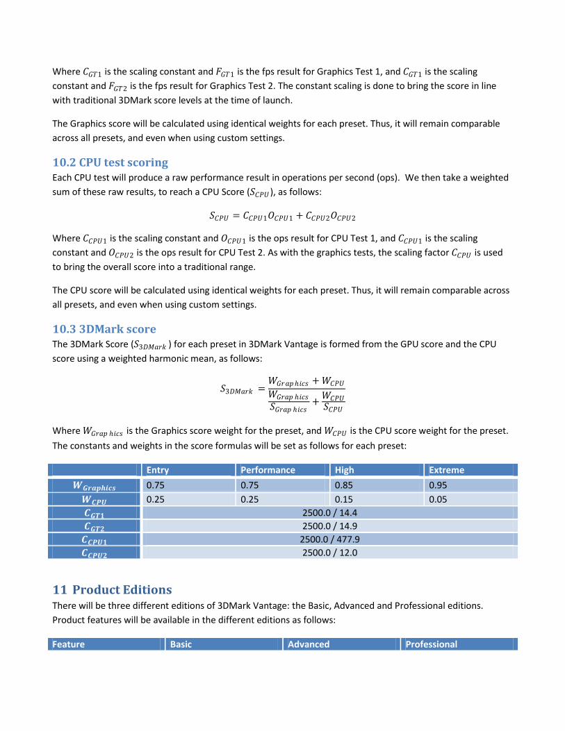
The constants and weights in the score formulas will be set as follows for each preset:
Entry Performance High Extreme
𝑾𝑮𝒓𝒂𝒑𝒉𝒊𝒄𝒔 0.75 0.75 0.85 0.95
𝑾𝑪𝑷𝑼 0.25 0.25 0.15 0.05
𝑪𝑮𝑻𝟏 2500.0 / 14.4
𝑪𝑮𝑻𝟐 2500.0 / 14.9
𝑪𝑪𝑷𝑼𝟏 2500.0 / 477.9
𝑪𝑪𝑷𝑼𝟐 2500.0 / 12.0
11 Product Editions There will be three different editions of 3DMark Vantage: the Basic, Advanced and Professional editions.
Product features will be available in the different editions as follows:
Feature Basic Advanced Professional
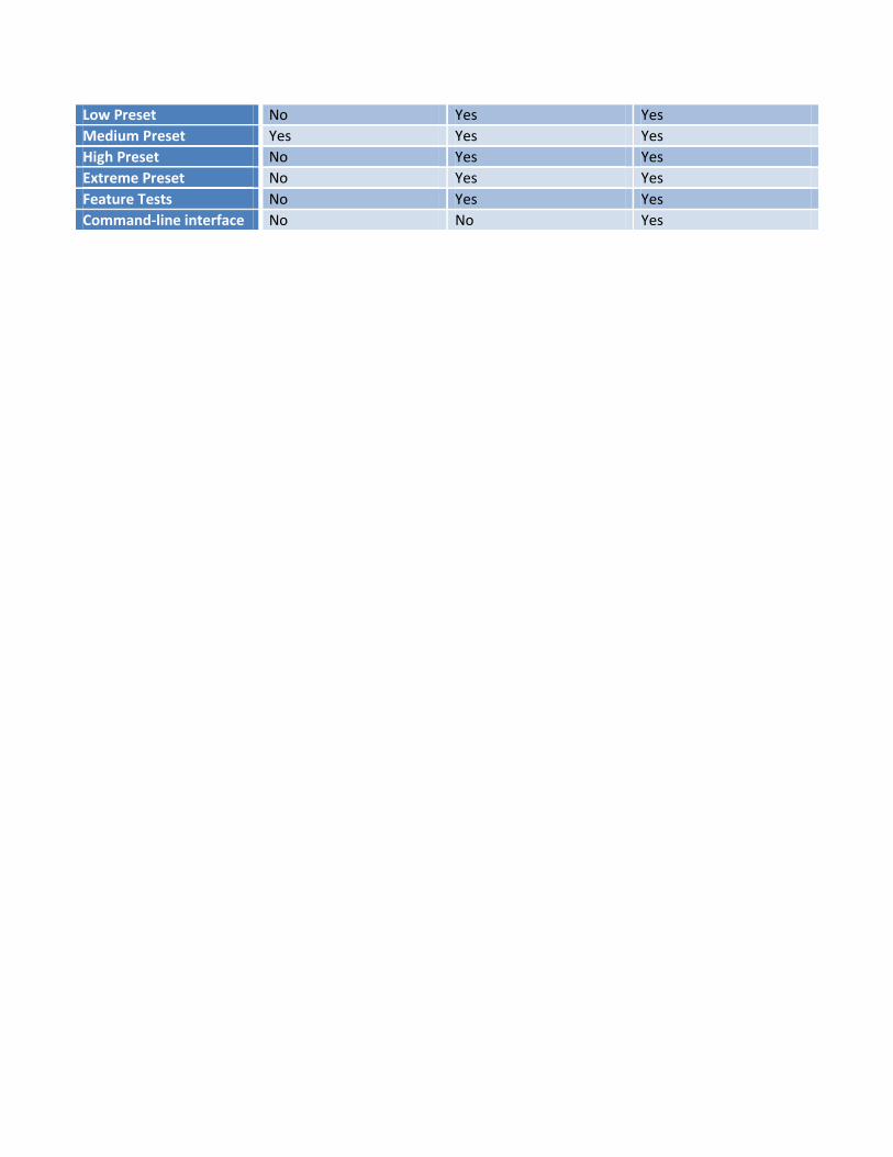
Low Preset No Yes Yes
Medium Preset Yes Yes Yes
High Preset No Yes Yes
Extreme Preset No Yes Yes
Feature Tests No Yes Yes
Command-line interface No No Yes