Embed Size (px)
Citation preview
Centre Scientifique et
Technique du Bâtiment 84 avenue Jean Jaurès CHAMPS-SUR-MARNE F-77447 Marne-la-Vallée Cedex 2 Tél. : (33) 01 64 68 82 82 Fax : (33) 01 60 05 70 37
Member of
www.eota.eu
Translations of this European Technical Assessment in other languages shall fully correspond to the original issued document and should be identified as such.
Communication of this European Technical Assessment, including transmission by electronic means, shall be in full. However, partial reproduction may be made, with the written consent of the issuing Technical Assessment Body. Any partial reproduction has to be identified as such.
European Technical Assessment
ETA-11/0495 of 29/01/2016
English translation prepared by CSTB - Original version in French language General Part
Nom commercial Trade name
PROTEC® FLAMME
Famille de produit Product family
Produits de protection au feu :
- Enduits projetés et kits d’enduits projetés resistant au feu
Fire protective products - Renderings and Rendering Kits intended for Fire Resisting Applications
Titulaire Manufacturer
RUAUD INDUSTRIES
ZI de la Croix Saint-Nicolas
18 rue Gustave Eiffel
94510 LA QUEUE EN BRIE
Usine de fabrication Manufacturing plants
RUAUD INDUSTRIES
ZI de la Croix Saint-Nicolas
18 rue Gustave Eiffel
94510 LA QUEUE EN BRIE
Cette evaluation contient: This Assessment contains
35 pages incluant 7 annexes qui font partie intégrante de cette évaluation 35 pages including 7 annexes which form an integral part of this assessment
Base de l‘ETE
Basis of ETA
ETAG 018: Partie 3, Version janvier 2006 modifié mai 2012, utilisée en tant que DEE
ETAG 018: Part 3, Edition January 2006, amended May 2012 used as EAD
European technical assessment ETA-11/0495
English translation prepared by CSTB
Page 2 of 35| 29/01/2016
SPECIFIC PART
1 Technical description of the product
PROTEC® FLAMME fire protective product is a sprayed fibrous product made of :
Biosoluble mineral fibers, white cement, gypsum (calcium hemihydrate).
The nature of building constructions to be protected are concrete structures, steel structures, concrete / profiled sheet steel composite slabs, timber floors.
PROTEC® FLAMME must be applied by using a bonding primer. See the components list in table 1.1 below :
Name Trade reference Characteristics Supplier
Primer (corrosion protection)
Alkyd family
Epoxy family
Galvanised steel
Market
Bonding agent BRL 150 to 200 g/m² RUAUD
Expanded metal rib lath Galvanised Z275 DX51D steel
Lath: 2510 mmx606 mm Thickness: 0,3 mm
Market
Fixing of expanded metal rib lath
Resined galvanised steel staples
Length : 25 mm
Width : 10,5 mm
Market
Protective material PROTEC® FLAMME ρ = (250 + 15%) kg/m3
e = 15 to 88 mm RUAUD
Table 1.1 : Component list
The rendering kit comprises the protective material PROTEC® FLAMME and the bonding agent BRL as given in table 1-1 above, correspond to “Option 2” as described in the foreword in ETAG 018-3. The rendering kit has been evaluated in the end use application, and is covered by CE marking of the kit.
The other additional components are not supplied by the ETA holder and are considered to be a final assembly under as in “Option 3”. Primers (corrosion protection) and a metal rib lath are used for some application of PROTEC® FLAMME. Primers are described in annex 4 and are used with steel structures. Metal rib lath is described in annex 6 and is used with timber structure. They are not part of the kit but have to be considered as additional components in the sense of the Note in the Foreword in ETAG 018-3.
European technical assessment ETA-11/0495
English translation prepared by CSTB
Page 3 of 35| 29/01/2016
2 Specification of the intended use in accordance with the applicable European Assessment Document (hereinafter EAD)
2.1 Intended use
Related to environmental conditions the rendering product is intended for internal and semi-exposed environmental conditions; use category Type Y , Z1 and Z2 as defined in ETAG 018-Part 3. This includes temperatures below 0 °C, but no exposure to rain and limited exposure to UV.
Related to use categories as defined in ETAG 018-Part 1, the fire protective performance of PROTEC® FLAMME has been assessed for the following applications:
Table 1-2: Intended use category
Protection of ETAG 018-1
reference
Load-bearing concrete elements Type 3
Load bearing steel elements Type 4
Load-bearing flat concrete profiled sheet composite elements
Type 5
Load bearing timber floors (not covered by types 1 – 9)
Type 10
2.2 Assumed working life
The provisions made in this ETA are based on an assumed intended working life of the product of 25 years, provided that the assembled product is subject to appropriate use and maintenance.
The indications given on the working life cannot be interpreted as a guarantee given by the producer, but are to be regarded only as a mean for choosing the right products in relation to the expected economically reasonable working life of the works. The user of the product must ensure, that the durability assessment that has been made, is relevant to the local conditions of use.
2.3 Manufacturing
The European Technical Assesment is issued for PROTEC® FLAMME on the basis of agreed data/information, deposited with CSTB, which identifies the product that has been assessed and judged.
Changes to the product or production process, which could result in this deposited data/information being incorrect, should be notified to CSTB before the changes are introduced. CSTB will decide whether or not such changes affect the ETA and consequently the validity of the CE marking on the basis of the ETA, and if so whether further assessment or alterations to the ETA shall be necessary.
The raw materials are mixed in a continuous process. The mix is put into bags. Each bag is marked. Bags are examined for visual defects and non-compliant bags are rejected.
2.4 Installation
The product shall be installed and used as described in this European Technical Assessment.
The arrangement and installation of the PROTEC® FLAMME shall be done in accordance with the details given in Annex 7.
European technical assessment ETA-11/0495
English translation prepared by CSTB
Page 4 of 35| 29/01/2016
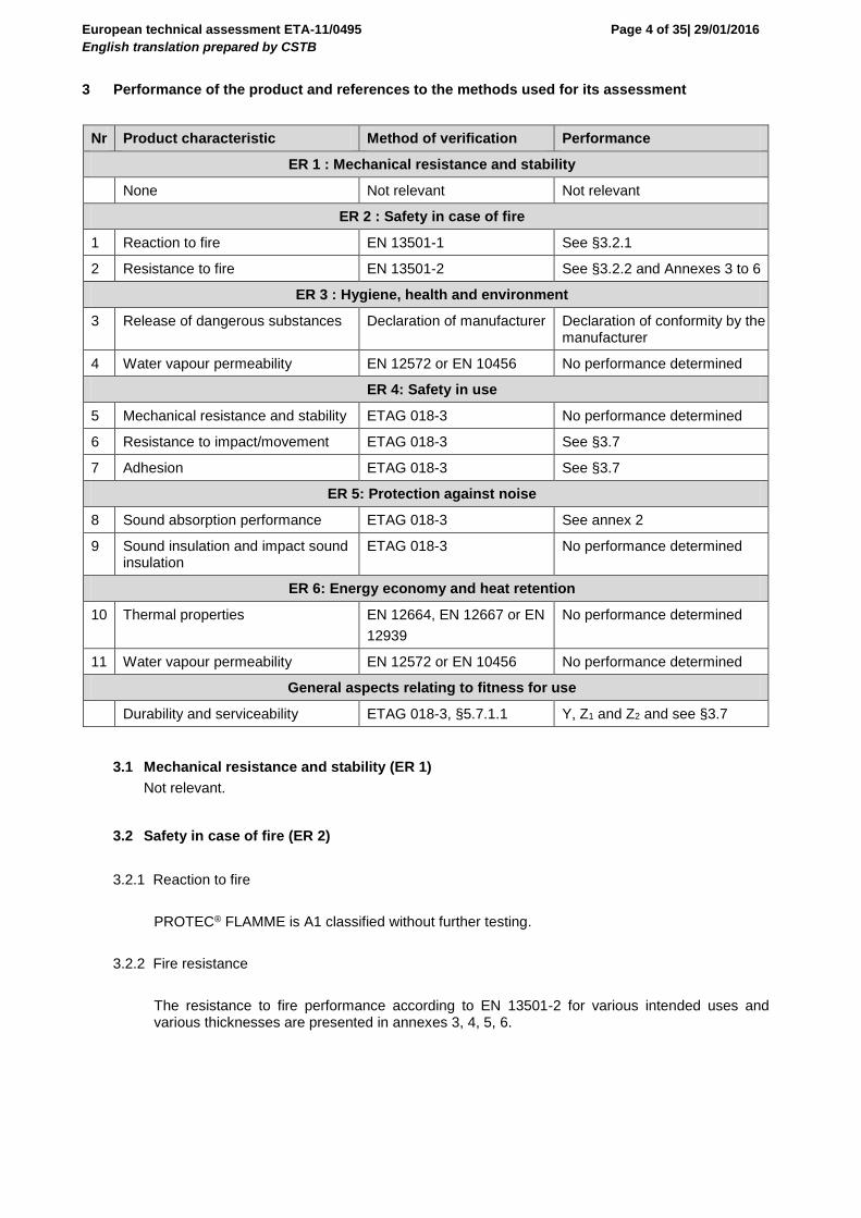
3 Performance of the product and references to the methods used for its assessment
Nr Product characteristic Method of verification Performance
ER 1 : Mechanical resistance and stability
None Not relevant Not relevant
ER 2 : Safety in case of fire
1 Reaction to fire EN 13501-1 See §3.2.1
2 Resistance to fire EN 13501-2 See §3.2.2 and Annexes 3 to 6
ER 3 : Hygiene, health and environment
3 Release of dangerous substances Declaration of manufacturer Declaration of conformity by the manufacturer
4 Water vapour permeability EN 12572 or EN 10456 No performance determined
ER 4: Safety in use
5 Mechanical resistance and stability ETAG 018-3 No performance determined
6 Resistance to impact/movement ETAG 018-3 See §3.7
7 Adhesion ETAG 018-3 See §3.7
ER 5: Protection against noise
8 Sound absorption performance ETAG 018-3 See annex 2
9 Sound insulation and impact sound insulation
ETAG 018-3 No performance determined
ER 6: Energy economy and heat retention
10 Thermal properties EN 12664, EN 12667 or EN
12939
No performance determined
11 Water vapour permeability EN 12572 or EN 10456 No performance determined
General aspects relating to fitness for use
Durability and serviceability ETAG 018-3, §5.7.1.1 Y, Z1 and Z2 and see §3.7
3.1 Mechanical resistance and stability (ER 1)
Not relevant.
3.2 Safety in case of fire (ER 2)
3.2.1 Reaction to fire
PROTEC® FLAMME is A1 classified without further testing.
3.2.2 Fire resistance
The resistance to fire performance according to EN 13501-2 for various intended uses and various thicknesses are presented in annexes 3, 4, 5, 6.

European technical assessment ETA-11/0495
English translation prepared by CSTB
Page 5 of 35| 29/01/2016
3.3 Hygiene, health and the environment (ER 3)
3.3.1 Release of dangerous substances
According to the manufacturer’s declaration the component PROTEC® FLAMME does not contain dangerous substances detailed in Council Directive 67/548/EEC and Regulation (EC) no 1272/2008 as well as EOTA TR 034 (General ER 3 Checklist for ETAGs/CUAPs/ETAs- Content and/or release of dangerous substances in products/kits), edition March 2012.
A written declaration in this respect was submitted by the ETA-holder. In addition to the specific clauses relating to dangerous substances contained in this European technical assesment, there may be other requirements applicable to the products falling within its scope (e.g. transposed European legislation and national laws, regulations and administrative provisions). In order to meet the provisions of the Construction Product Regulation, these requirements need also to be complied with, when and where they apply
3.3.2 Water vapour permeability
No Performance Determined
3.4 Safety in use (ER 4)
3.4.1 Mechanical resistance and stability
No Performance Determined
3.4.2 Resistance to impact/movement
No Performance Determined.
3.4.3 Adhesion
See §3.7.
3.5 Protection against noise (ER 5)
3.5.1 Sound absorption performance
Sound absorption measurement results according to EN ISO 354 and EN ISO 11654 are given in annex 2.
3.5.2 – Sound insulation and impact sound insulation
No Performance Determined.
European technical assessment ETA-11/0495
English translation prepared by CSTB
Page 6 of 35| 29/01/2016
3.6 Energy economy and heat retention (ER 6)
3.6.1 Thermal properties
No Performance Determined.
3.6.2 Water vapour permeability
No Performance Determined.
3.7 General aspects relating to fitness for use and durability
PROTEC® FLAMME has been tested for an intended use category Y , Z1 and Z2 and the tests results have shown a compliance for temperatures below 0 °C, but no exposure to rain and limited exposure to UV.
3.7.1 Durability
Resistance to UV-exposure
This characteristic is not relevant for the intended use (semi-exposed, type Y).
Resistance to deterioration caused by heat and rain
This characteristic is not relevant for the intended use (semi-exposed, type Y).
Resistance to deterioration caused by high humidity
In accordance with ETAG 018-3, the PROTEC® FLAMME fire protective product are resistant to
high humidity.
Resistance to deterioration caused by heat and cold
In accordance with ETAG 018-3, the PROTEC® FLAMME fire protective product are resistant to
heat/cold cycles.
Resistance to deterioration caused by freezing and thawing
In accordance with ETAG 018-3, the PROTEC® FLAMME fire protective product are resistant to
freeze/thaw cycles.
Resistance to corrosion of a steel substrate by the rendering
No performance determined.
Resistance to corrosion of the fixings by the rendering
Not relevant.
European technical assessment ETA-11/0495
English translation prepared by CSTB
Page 7 of 35| 29/01/2016
3.7.2 Serviceability requirements
3.7.2.1 Mechanical resistance and stability:
Pull out resistance of discontinuous fixings
Not relevant.
Bending resistance of discontinuous fixings (for steel)
Not relevant.
Pull out resistance of keying mesh
Not relevant.
Pull out resistance of rendering
See clause adhesion.
3.7.2.2 Resistance to impact/movement
Resistance to functional failure from hard body impact load – 0,5 kg steel ball
No performance determined.
Resistance to functional failure from soft body impact – 50 kg bag
No performance determined.
Flexural performance
No performance determined.
3.7.2.3 Air erosion
No performance determined.
3.7.2.4 Water vapour permeability
No performance determined.
3.7.2.5 Water absorption (capillarity test)
Not relevant for the intended use (semi-exposed type Y).
3.7.2.6 Adhesion
In accordance with ETAG 018-3 and EGOLF method SM/5.
The adhesion/cohesion of the PROTEC® FLAMME fire protective product was measured on numerous conditions of installed thickness and preparation of the substrates. See Annex 2, in this ETA for a tensile bond strength guidance value.
European technical assessment ETA-11/0495
English translation prepared by CSTB
Page 8 of 35| 29/01/2016
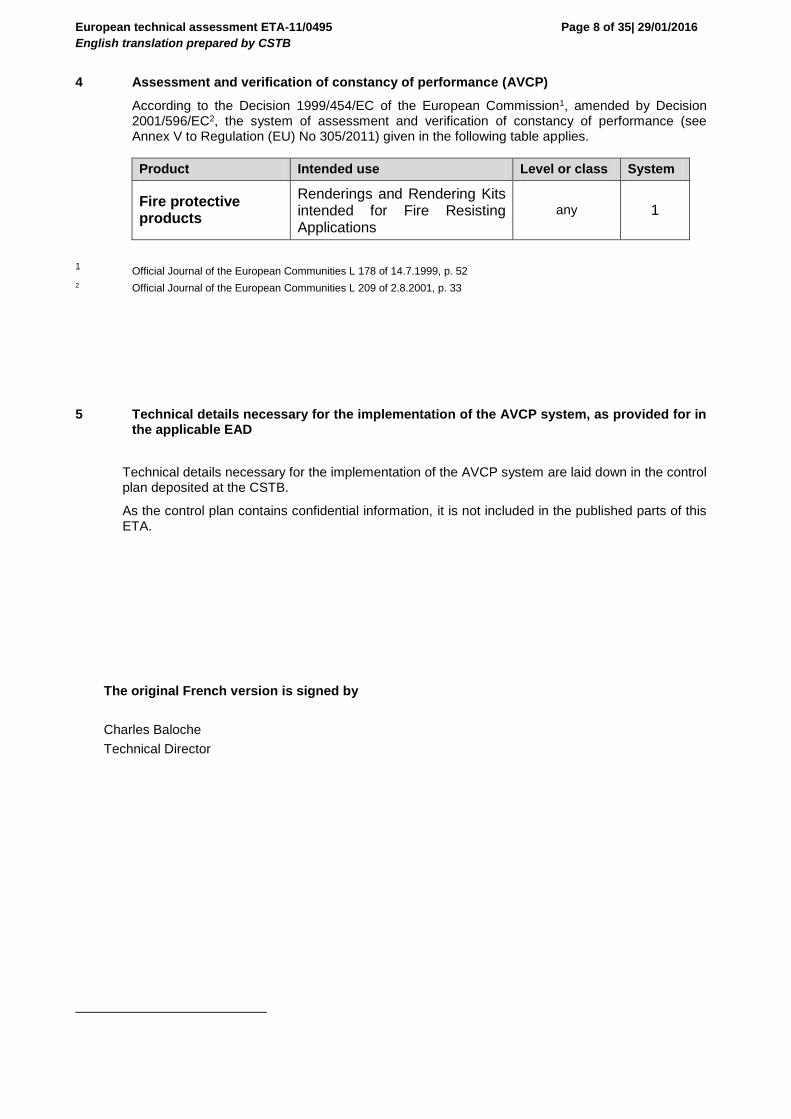
4 Assessment and verification of constancy of performance (AVCP)
According to the Decision 1999/454/EC of the European Commission1, amended by Decision 2001/596/EC2, the system of assessment and verification of constancy of performance (see Annex V to Regulation (EU) No 305/2011) given in the following table applies.
Product Intended use Level or class System
Fire protective products
Renderings and Rendering Kits intended for Fire Resisting Applications
any 1
1 Official Journal of the European Communities L 178 of 14.7.1999, p. 52
2 Official Journal of the European Communities L 209 of 2.8.2001, p. 33
5 Technical details necessary for the implementation of the AVCP system, as provided for in the applicable EAD
Technical details necessary for the implementation of the AVCP system are laid down in the control plan deposited at the CSTB.
As the control plan contains confidential information, it is not included in the published parts of this ETA.
The original French version is signed by
Charles Baloche
Technical Director
European technical assessment ETA-11/0495
English translation prepared by CSTB
Page 9 of 35| 29/01/2016
Sprayed fire protective product PROTEC® FLAMME
Annexes 1 to 6
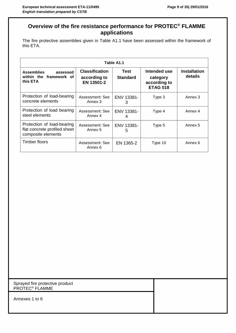
Overview of the fire resistance performance for PROTEC® FLAMME applications
The fire protective assemblies given in Table A1.1 have been assessed within the framework of this ETA.
Table A1.1
Assemblies assessed within the framework of this ETA
Classification
according to EN 13501-2
Test
Standard
Intended use
category according to
ETAG 018
Installation details
Protection of load-bearing concrete elements
Assessment: See Annex 3
ENV 13381-3
Type 3 Annex 3
Protection of load bearing steel elements
Assessment: See Annex 4
ENV 13381-4
Type 4 Annex 4
Protection of load-bearing flat concrete profiled sheet composite elements
Assessment: See Annex 5
ENV 13381-5
Type 5 Annex 5
Timber floors Assessment: See Annex 6
EN 1365-2 Type 10 Annex 6
European technical assessment ETA-11/0495
English translation prepared by CSTB
Page 10 of 35| 29/01/2016
Sprayed fire protective product PROTEC® FLAMME
Annexes 1 to 6
Annex 2:
Additional properties
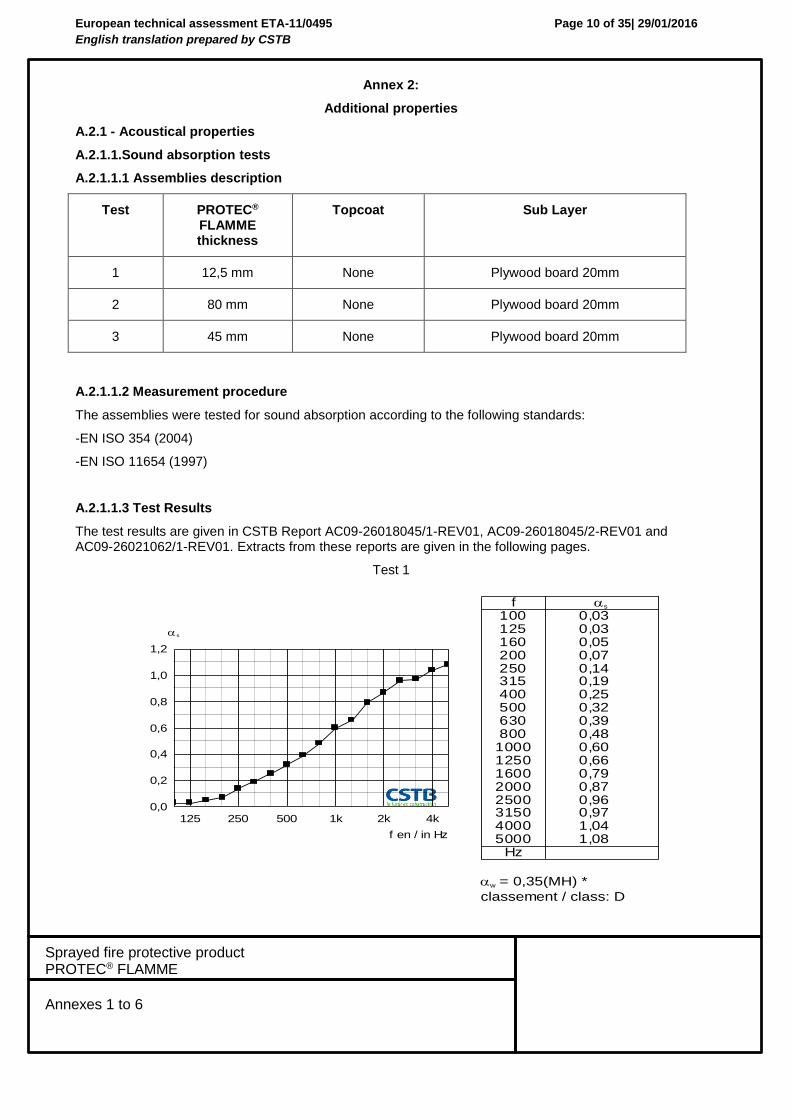
A.2.1 - Acoustical properties
A.2.1.1.Sound absorption tests
A.2.1.1.1 Assemblies description
Test PROTEC® FLAMME thickness
Topcoat Sub Layer
1 12,5 mm None Plywood board 20mm
2 80 mm None Plywood board 20mm
3 45 mm None Plywood board 20mm
A.2.1.1.2 Measurement procedure
The assemblies were tested for sound absorption according to the following standards:
-EN ISO 354 (2004)
-EN ISO 11654 (1997)
A.2.1.1.3 Test Results
The test results are given in CSTB Report AC09-26018045/1-REV01, AC09-26018045/2-REV01 and AC09-26021062/1-REV01. Extracts from these reports are given in the following pages.
Test 1
f10012516020025031540050063080010001250160020002500315040005000
Hz
s
30,030,050,070,041,091,052,023,093,084,006,066,097,078,069,079,040,180,1
w = 0,35(MH) *
classement / class: D
1,2
1,0
0,8
0,6
0,4
0,2
0,0125 250 500 1k 2k 4k
f en / in Hz
s
European technical assessment ETA-11/0495
English translation prepared by CSTB
Page 11 of 35| 29/01/2016
Sprayed fire protective product PROTEC® FLAMME
Annexes 1 to 6
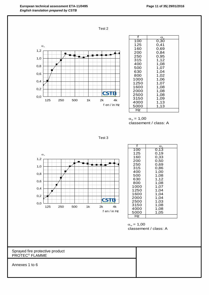
Test 2
Test 3
f10012516020025031540050063080010001250160020002500315040005000
Hz
s
03,014,096,048,059,021,180,170,140,120,160,170,180,180,180,190,131,131,1
w = 1,00
classement / class: A
1,2
1,0
0,8
0,6
0,4
0,2
0,0125 250 500 1k 2k 4k
f en / in Hz
s
f10012516020025031540050063080010001250160020002500315040005000
Hz
s
31,091,033,005,096,068,000,180,121,180,170,140,140,140,130,180,180,150,1
w = 1,00
classement / class: A
1,2
1,0
0,8
0,6
0,4
0,2
0,0125 250 500 1k 2k 4k
f en / in Hz
s
European technical assessment ETA-11/0495
English translation prepared by CSTB
Page 12 of 35| 29/01/2016
Sprayed fire protective product PROTEC® FLAMME
Annexes 1 to 6
A.2.2 – Method for determination of tensile bond strength on site
A.2.2.1 Introduction
This document describes methods for onsite measurement of the tensile bond strength of the rendering kit BRL and PROTEC® FLAMME, at room temperature.
These methods derive from the EGOLF SM5 method.
A.2.2.2 Tensile bond strength
The tensile bond strength of the rendering BRL and PROTEC® FLAMME is determined by measuring pull off force that is necessary to cause a failure :
of the bond between the support and the rendering kit BRL and PROTEC® FLAMME (adhesive failure),
within the depth of the sprayed the rendering kit BRL and PROTEC® FLAMME (cohesive failure).
A.2.2.3 Preparation of the test
This test shall be carried out when the rendering kit BRL and PROTEC® FLAMME is properly stable. Depending on the temperature and relative humidity, this should be around one month after the spraying of PROTEC® FLAMME.
Square pieces (10 x 10 cm) shall be cut in the rendering kit up to the support. Those elements shall not be located at less than 50mm from the edge of the support, or from another test element. The cutting of those elements shall be carried out with great care to prevent any damage that would reduce the tensile bonding strength of the system.
The plywood piece shall be glued onto the cut elements. Wait 24 hours.
A.2.2.4 Test Method
Hang the bucket with the tie up. Insert water into the bucket until failure of rendering.
Count the water volume used.
A.2.2.5 Results interpretation
The test shall end when a failure occurs in the adherence between the rendering kit BRL and PROTEC®
FLAMME and the support or when the cohesion within PROTEC® FLAMME fails.
The applied force at the time of the failure shall be recorded. The type of failure : adhesive or cohesive shall also be recorded.
European technical assessment ETA-11/0495
English translation prepared by CSTB
Page 13 of 35| 29/01/2016
Sprayed fire protective product PROTEC® FLAMME
Annexes 1 to 6
A.2.2.6 Number of tests
At least 8 elements shall be tested for each support and each thickness.
A.2.2.7 Acceptability of the tensile bond strength
In accordance with the test method described in EGOLF SM5.
Bonding properties of PROTEC® FLAMME on concrete structures
The rendering kit has a tensile bond strength of ≥ 3,56 kPa. This is a guidance value and does not reflect a statistical evaluation, nor a minimum guaranteed value. All results have shown a cohesion failure.
The rendering has sufficient cohesion to support its own mass. The rendering is not intended to support additional loads.
Bonding properties of PROTEC® FLAMME on steel structures
The rendering kit has a tensile bond strength of ≥ 6,58 kPa. This is a guidance value and does not reflect a statistical evaluation, nor a minimum guaranteed value. All results have shown a cohesion failure.
Bonding properties of PROTEC® FLAMME on flat concrete profiled sheet steel composite structures
The rendering kit has a tensile bond strength of ≥ 2,94 kPa. This is a guidance value and does not reflect a statistical evaluation, nor a minimum guaranteed value. All results have shown a cohesion failure.
The rendering has sufficient cohesion to support its own mass. The rendering is not intended to support additional loads.
European technical assessment ETA-11/0495
English translation prepared by CSTB
Page 14 of 35| 29/01/2016
Sprayed fire protective product PROTEC® FLAMME
Annexes 1 to 6
Annex 3 :
Specification and assessment of fire protection of a load bearing concrete assembly (intended use type 3) protected by PROTEC® FLAMME rendering
A.3.1 Classification
The assembly described in this annex has been tested and assessed according to ENV 13381-3 and classified in accordance with EN 13501-2.
The maximum duration of the exposure to the standard time temperature curve as defined in EN 1363-1, section 5.1.1, is 360 min depending on the type of concrete structures and the thickness of the PROTEC® FLAMME applied.
The assessment of the insulation efficiency and the equivalent thickness of concrete are given in clause A.3.3.
A.3.2 Installation requirements
A.3.2.1. Supporting structure
PROTEC® FLAMME is applicable to all concrete slabs and walls with fire exposure from one side only, in both horizontal and vertical orientation.
PROTEC® FLAMME is applicable to concrete beams and columns exposed to fire from more than one side, in both horizontal and vertical orientation.
Specifications for the components are given in Table A.3.1.
Table A.3.1
Element Identification Characteristics Mounting and fixing
Load bearing concrete beam
Concrete, silicious aggregates
- Density 2330 kg/m³ ± 15 %
- Width of the beam ≥ 150 mm
- Casted with release agent applied in the mould, belonging to the families of mineral oil or emulsions. - Surface shall be free of dust and bare.
Load bearing concrete slab or wall
Concrete silicious aggregates
- Density 2330 kg/m³ ± 15 %
- Thickness: ≥ 140 mm
- Casted with release agent applied in the mould, belonging to the families of mineral oil or emulsions.
- Surface shall be free of dust and bare.
A.3.2.2 – Bonding primer prior to application of PROTEC® FLAMME
If the concrete support is sound, then, whatever the release agent used to cast the concrete as mentioned above is, the concrete structures are treated with bonding primer BRL before the application of PROTEC® FLAMME.
The BRL is applied with a roll and/or a brush on all parts to be protected with PROTEC® FLAMME.
Applied ratio : 150 to 200 g/m² around.
European technical assessment ETA-11/0495
English translation prepared by CSTB
Page 15 of 35| 29/01/2016
Sprayed fire protective product PROTEC® FLAMME
Annexes 1 to 6
Then, PROTEC® FLAMME spray material is applied some minutes after the application of BRL, once the bonding primer tacks.
Specifications for the components are given in Table A.3.2
Table A.3.2
Element Identification Characteristics Mounting and fixing
Primer BRL 150 to 200 g/m² - Roll or brush applied to all parts to be protected by PROTEC® FLAMME.
- Applied quantity: 150 to 200 g/m²
A.3.2.3 – Fire protective rendering
Product PROTEC® FLAMME is applied on the apparent sides of concrete structures to be protected, following their shape.
PROTEC® FLAMME is continuously applied with a spraying machine. During the application, the thickness of protective material is regularly controlled with a pin calibre. When the required thickness is reached, PROTEC® FLAMME is rolled to have a smooth surface and to level outstanding fibres.
Specifications for the components are given in Table A.3.3
Table A.3.3
Element Identification Characteristics Mounting and fixing
Rendering PROTEC® FLAMME - Average thicknesses: from 15 to 88 mm, according to the assessment rules.
Density : 250 kg/m³ ± 15 %
- Sprayed in 1 layer - After application the PROTEC® FLAMME is rolled to smooth and level the surface
A.3.3 Assessment of the fire performance of PROTEC® FLAMME on concrete structures
A.3.3.1 Assessment report
The assessment method used to assess the fire protection performances of product PROTEC® FLAMME when applied on concrete structures is as follows :
Type of structure Standard used for assessment
Assessment report reference
Concrete ENV 13381-3 RS09-156
European technical assessment ETA-11/0495
English translation prepared by CSTB
Page 16 of 35| 29/01/2016
Sprayed fire protective product PROTEC® FLAMME
Annexes 1 to 6
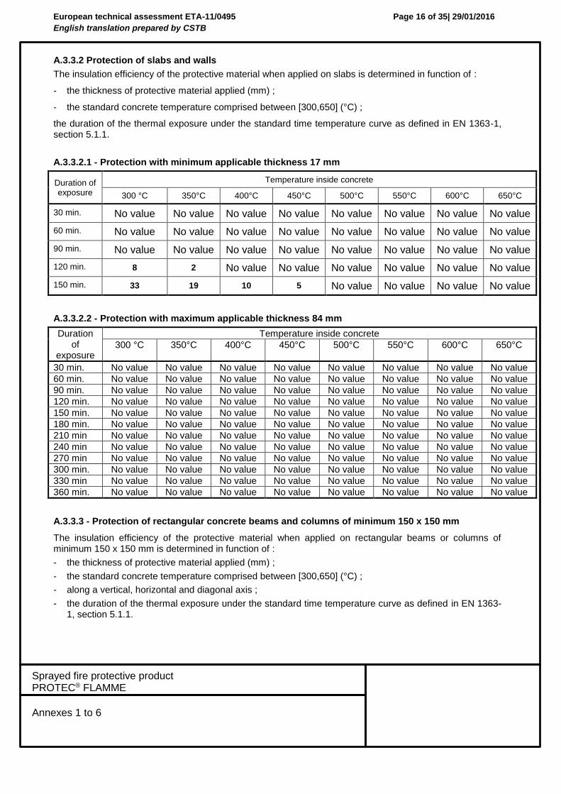
A.3.3.2 Protection of slabs and walls
The insulation efficiency of the protective material when applied on slabs is determined in function of :
- the thickness of protective material applied (mm) ;
- the standard concrete temperature comprised between [300,650] (°C) ;
the duration of the thermal exposure under the standard time temperature curve as defined in EN 1363-1, section 5.1.1.
A.3.3.2.1 - Protection with minimum applicable thickness 17 mm
Duration of exposure
Temperature inside concrete
300 °C 350°C 400°C 450°C 500°C 550°C 600°C 650°C
30 min. No value No value No value No value No value No value No value No value
60 min. No value No value No value No value No value No value No value No value
90 min. No value No value No value No value No value No value No value No value
120 min. 8 2 No value No value No value No value No value No value
150 min. 33 19 10 5 No value No value No value No value
A.3.3.2.2 - Protection with maximum applicable thickness 84 mm
Duration of
exposure
Temperature inside concrete
300 °C 350°C 400°C 450°C 500°C 550°C 600°C 650°C
30 min. No value No value No value No value No value No value No value No value
60 min. No value No value No value No value No value No value No value No value
90 min. No value No value No value No value No value No value No value No value
120 min. No value No value No value No value No value No value No value No value
150 min. No value No value No value No value No value No value No value No value
180 min. No value No value No value No value No value No value No value No value
210 min No value No value No value No value No value No value No value No value
240 min No value No value No value No value No value No value No value No value
270 min No value No value No value No value No value No value No value No value
300 min. No value No value No value No value No value No value No value No value
330 min No value No value No value No value No value No value No value No value
360 min. No value No value No value No value No value No value No value No value
A.3.3.3 - Protection of rectangular concrete beams and columns of minimum 150 x 150 mm
The insulation efficiency of the protective material when applied on rectangular beams or columns of minimum 150 x 150 mm is determined in function of :
- the thickness of protective material applied (mm) ;
- the standard concrete temperature comprised between [300,650] (°C) ;
- along a vertical, horizontal and diagonal axis ;
- the duration of the thermal exposure under the standard time temperature curve as defined in EN 1363-1, section 5.1.1.
European technical assessment ETA-11/0495
English translation prepared by CSTB
Page 17 of 35| 29/01/2016
Sprayed fire protective product PROTEC® FLAMME
Annexes 1 to 6
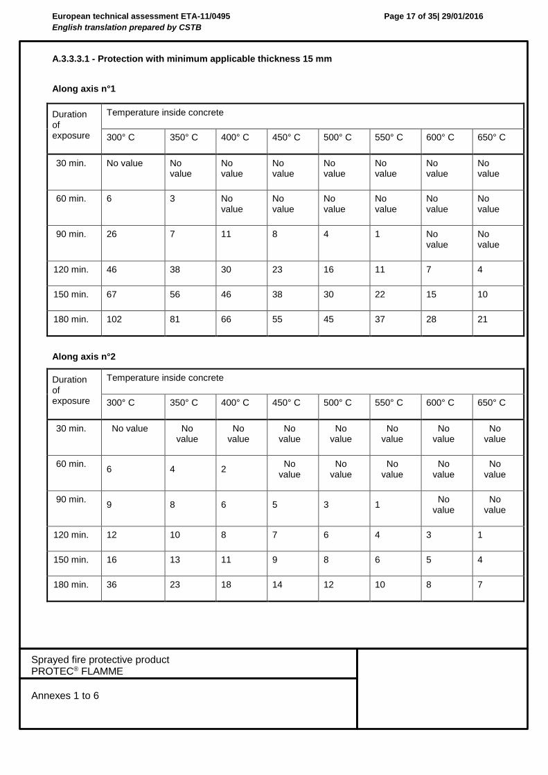
A.3.3.3.1 - Protection with minimum applicable thickness 15 mm
Along axis n°1
Along axis n°2
Duration of exposure
Temperature inside concrete
300° C 350° C 400° C 450° C 500° C 550° C 600° C 650° C
30 min. No value No value
No value
No value
No value
No value
No value
No value
60 min. 6 3 No value
No value
No value
No value
No value
No value
90 min. 26 7 11 8 4 1 No value
No value
120 min. 46 38 30 23 16 11 7 4
150 min. 67 56 46 38 30 22 15 10
180 min. 102 81 66 55 45 37 28 21
Duration of exposure
Temperature inside concrete
300° C 350° C 400° C 450° C 500° C 550° C 600° C 650° C
30 min. No value No value
No value
No value
No value
No value
No value
No value
60 min. 6 4 2
No value
No value
No value
No value
No value
90 min. 9 8 6 5 3 1
No value
No value
120 min. 12 10 8 7 6 4 3 1
150 min. 16 13 11 9 8 6 5 4
180 min. 36 23 18 14 12 10 8 7
European technical assessment ETA-11/0495
English translation prepared by CSTB
Page 18 of 35| 29/01/2016
Sprayed fire protective product PROTEC® FLAMME
Annexes 1 to 6
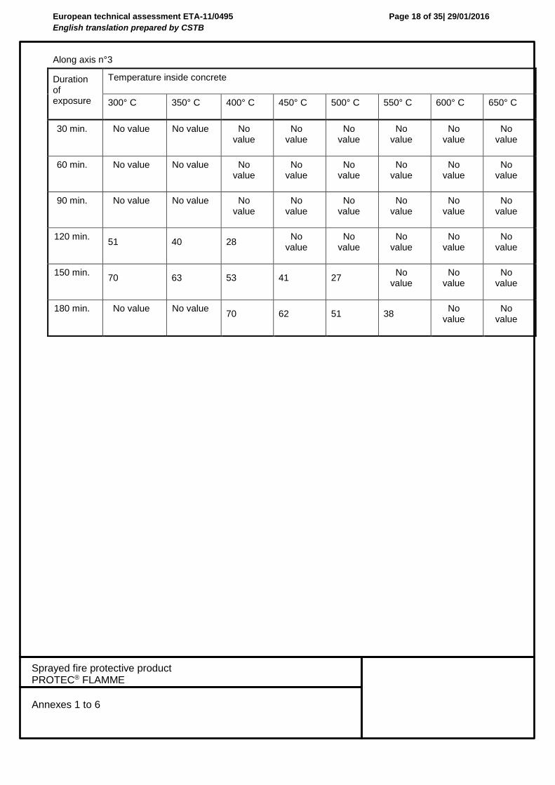
Along axis n°3
Duration of exposure
Temperature inside concrete
300° C 350° C 400° C 450° C 500° C 550° C 600° C 650° C
30 min. No value No value No value
No value
No value
No value
No value
No value
60 min. No value No value No value
No value
No value
No value
No value
No value
90 min. No value No value No value
No value
No value
No value
No value
No value
120 min. 51 40 28
No value
No value
No value
No value
No value
150 min. 70 63 53 41 27
No value
No value
No value
180 min. No value No value 70 62 51 38
No value
No value
European technical assessment ETA-11/0495
English translation prepared by CSTB
Page 19 of 35| 29/01/2016
Sprayed fire protective product PROTEC® FLAMME
Annexes 1 to 6
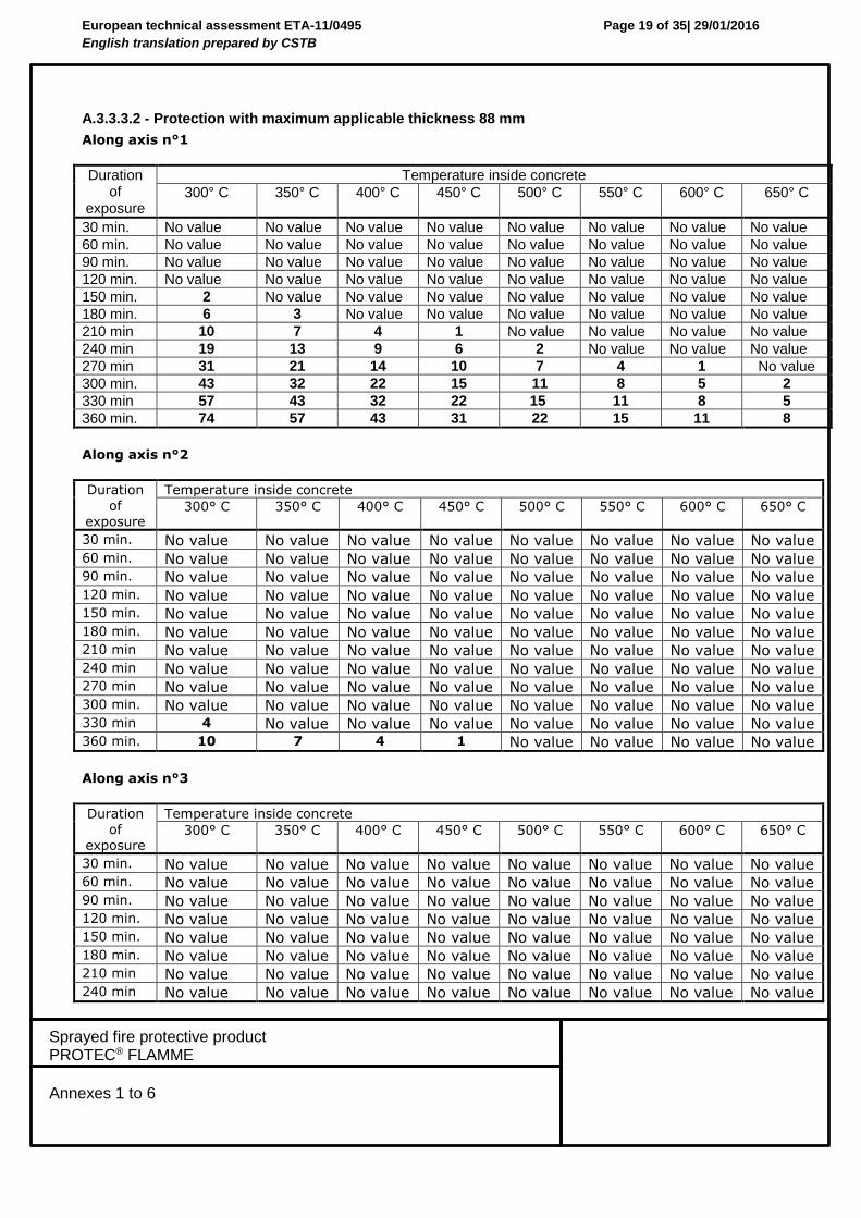
A.3.3.3.2 - Protection with maximum applicable thickness 88 mm
Along axis n°1
Duration of
exposure
Temperature inside concrete
300° C 350° C 400° C 450° C 500° C 550° C 600° C 650° C
30 min. No value No value No value No value No value No value No value No value
60 min. No value No value No value No value No value No value No value No value
90 min. No value No value No value No value No value No value No value No value
120 min. No value No value No value No value No value No value No value No value
150 min. 2 No value No value No value No value No value No value No value
180 min. 6 3 No value No value No value No value No value No value
210 min 10 7 4 1 No value No value No value No value
240 min 19 13 9 6 2 No value No value No value
270 min 31 21 14 10 7 4 1 No value
300 min. 43 32 22 15 11 8 5 2
330 min 57 43 32 22 15 11 8 5
360 min. 74 57 43 31 22 15 11 8
Along axis n°2
Duration
of exposure
Temperature inside concrete
300° C 350° C 400° C 450° C 500° C 550° C 600° C 650° C
30 min. No value No value No value No value No value No value No value No value
60 min. No value No value No value No value No value No value No value No value
90 min. No value No value No value No value No value No value No value No value
120 min. No value No value No value No value No value No value No value No value
150 min. No value No value No value No value No value No value No value No value
180 min. No value No value No value No value No value No value No value No value
210 min No value No value No value No value No value No value No value No value
240 min No value No value No value No value No value No value No value No value
270 min No value No value No value No value No value No value No value No value
300 min. No value No value No value No value No value No value No value No value
330 min 4 No value No value No value No value No value No value No value
360 min. 10 7 4 1 No value No value No value No value
Along axis n°3
Duration of
exposure
Temperature inside concrete
300° C 350° C 400° C 450° C 500° C 550° C 600° C 650° C
30 min. No value No value No value No value No value No value No value No value
60 min. No value No value No value No value No value No value No value No value
90 min. No value No value No value No value No value No value No value No value
120 min. No value No value No value No value No value No value No value No value
150 min. No value No value No value No value No value No value No value No value
180 min. No value No value No value No value No value No value No value No value
210 min No value No value No value No value No value No value No value No value
240 min No value No value No value No value No value No value No value No value
European technical assessment ETA-11/0495
English translation prepared by CSTB
Page 20 of 35| 29/01/2016
Sprayed fire protective product PROTEC® FLAMME
Annexes 1 to 6
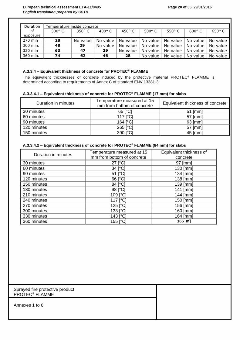
Duration of
exposure
Temperature inside concrete
300° C 350° C 400° C 450° C 500° C 550° C 600° C 650° C
270 min 28 No value No value No value No value No value No value No value
300 min. 48 29 No value No value No value No value No value No value
330 min 63 47 29 No value No value No value No value No value
360 min. 74 62 46 28 No value No value No value No value
A.3.3.4 – Equivalent thickness of concrete for PROTEC® FLAMME
The equivalent thicknesses of concrete induced by the protective material PROTEC® FLAMME is determined according to requirements of Annex C of standard ENV 13381-3.
A.3.3.4.1 – Equivalent thickness of concrete for PROTEC® FLAMME (17 mm) for slabs
Duration in minutes Temperature measured at 15 mm from bottom of concrete
Equivalent thickness of concrete
30 minutes 65 [°C] 51 [mm]
60 minutes 117 [°C] 57 [mm]
90 minutes 164 [°C] 63 [mm]
120 minutes 265 [°C] 57 [mm]
150 minutes 390 [°C] 45 [mm]
A.3.3.4.2 – Equivalent thickness of concrete for PROTEC® FLAMME (84 mm) for slabs
Duration in minutes Temperature measured at 15 mm from bottom of concrete
Equivalent thickness of concrete
30 minutes 27 [°C] 97 [mm]
60 minutes 34 [°C] 130 [mm]
90 minutes 51 [°C] 134 [mm]
120 minutes 66 [°C] 138 [mm]
150 minutes 84 [°C] 139 [mm]
180 minutes 98 [°C] 141 [mm]
210 minutes 109 [°C] 144 [mm]
240 minutes 117 [°C] 150 [mm]
270 minutes 125 [°C] 156 [mm]
300 minutes. 133 [°C] 160 [mm]
330 minutes 143 [°C] 164 [mm]
360 minutes 155 [°C] 165 m]
European technical assessment ETA-11/0495
English translation prepared by CSTB
Page 21 of 35| 29/01/2016
Sprayed fire protective product PROTEC® FLAMME
Annexes 1 to 6
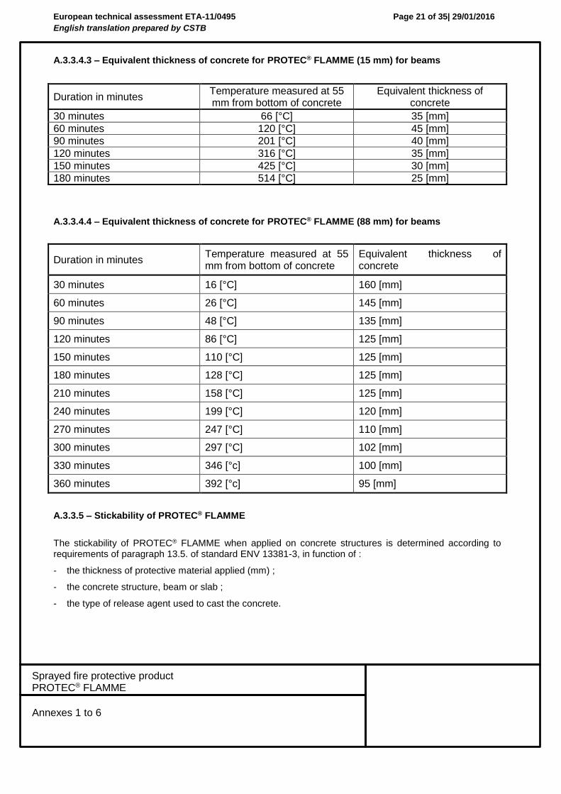
A.3.3.4.3 – Equivalent thickness of concrete for PROTEC® FLAMME (15 mm) for beams
Duration in minutes Temperature measured at 55 mm from bottom of concrete
Equivalent thickness of concrete
30 minutes 66 [°C] 35 [mm]
60 minutes 120 [°C] 45 [mm]
90 minutes 201 [°C] 40 [mm]
120 minutes 316 [°C] 35 [mm]
150 minutes 425 [°C] 30 [mm]
180 minutes 514 [°C] 25 [mm]
A.3.3.4.4 – Equivalent thickness of concrete for PROTEC® FLAMME (88 mm) for beams
Duration in minutes Temperature measured at 55 mm from bottom of concrete
Equivalent thickness of concrete
30 minutes 16 [°C] 160 [mm]
60 minutes 26 [°C] 145 [mm]
90 minutes 48 [°C] 135 [mm]
120 minutes 86 [°C] 125 [mm]
150 minutes 110 [°C] 125 [mm]
180 minutes 128 [°C] 125 [mm]
210 minutes 158 [°C] 125 [mm]
240 minutes 199 [°C] 120 [mm]
270 minutes 247 [°C] 110 [mm]
300 minutes 297 [°C] 102 [mm]
330 minutes 346 [°c] 100 [mm]
360 minutes 392 [°c] 95 [mm]
A.3.3.5 – Stickability of PROTEC® FLAMME
The stickability of PROTEC® FLAMME when applied on concrete structures is determined according to requirements of paragraph 13.5. of standard ENV 13381-3, in function of :
- the thickness of protective material applied (mm) ;
- the concrete structure, beam or slab ;
- the type of release agent used to cast the concrete.
European technical assessment ETA-11/0495
English translation prepared by CSTB
Page 22 of 35| 29/01/2016
Sprayed fire protective product PROTEC® FLAMME
Annexes 1 to 6
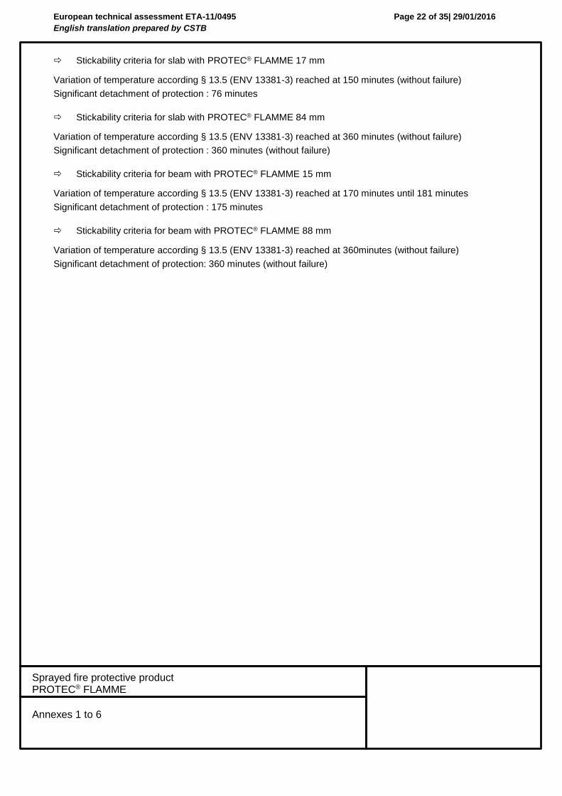
Stickability criteria for slab with PROTEC® FLAMME 17 mm
Variation of temperature according § 13.5 (ENV 13381-3) reached at 150 minutes (without failure)
Significant detachment of protection : 76 minutes
Stickability criteria for slab with PROTEC® FLAMME 84 mm
Variation of temperature according § 13.5 (ENV 13381-3) reached at 360 minutes (without failure)
Significant detachment of protection : 360 minutes (without failure)
Stickability criteria for beam with PROTEC® FLAMME 15 mm
Variation of temperature according § 13.5 (ENV 13381-3) reached at 170 minutes until 181 minutes
Significant detachment of protection : 175 minutes
Stickability criteria for beam with PROTEC® FLAMME 88 mm
Variation of temperature according § 13.5 (ENV 13381-3) reached at 360minutes (without failure)
Significant detachment of protection: 360 minutes (without failure)
European technical assessment ETA-11/0495
English translation prepared by CSTB
Page 23 of 35| 29/01/2016
Sprayed fire protective product PROTEC® FLAMME
Annexes 1 to 6
Annex 4 :
Specification and assessment of fire protection of a load bearing steel elements (intended use type 4) protected by PROTEC® FLAMME rendering
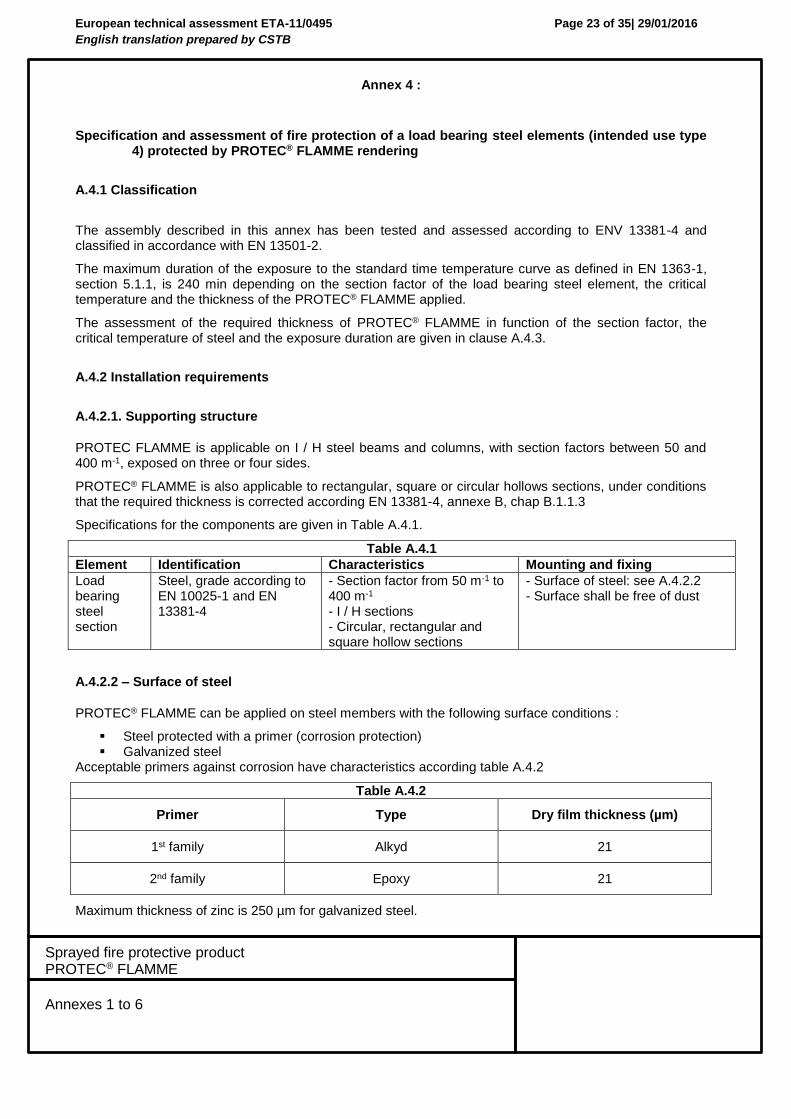
A.4.1 Classification
The assembly described in this annex has been tested and assessed according to ENV 13381-4 and classified in accordance with EN 13501-2.
The maximum duration of the exposure to the standard time temperature curve as defined in EN 1363-1, section 5.1.1, is 240 min depending on the section factor of the load bearing steel element, the critical temperature and the thickness of the PROTEC® FLAMME applied.
The assessment of the required thickness of PROTEC® FLAMME in function of the section factor, the critical temperature of steel and the exposure duration are given in clause A.4.3.
A.4.2 Installation requirements
A.4.2.1. Supporting structure
PROTEC FLAMME is applicable on I / H steel beams and columns, with section factors between 50 and 400 m-1, exposed on three or four sides.
PROTEC® FLAMME is also applicable to rectangular, square or circular hollows sections, under conditions that the required thickness is corrected according EN 13381-4, annexe B, chap B.1.1.3
Specifications for the components are given in Table A.4.1.
Table A.4.1
Element Identification Characteristics Mounting and fixing
Load bearing steel section
Steel, grade according to EN 10025-1 and EN 13381-4
- Section factor from 50 m-1 to 400 m-1 - I / H sections - Circular, rectangular and square hollow sections
- Surface of steel: see A.4.2.2 - Surface shall be free of dust
A.4.2.2 – Surface of steel
PROTEC® FLAMME can be applied on steel members with the following surface conditions :
Steel protected with a primer (corrosion protection) Galvanized steel
Acceptable primers against corrosion have characteristics according table A.4.2
Table A.4.2
Primer Type Dry film thickness (µm)
1st family Alkyd 21
2nd family Epoxy 21
Maximum thickness of zinc is 250 µm for galvanized steel.
European technical assessment ETA-11/0495
English translation prepared by CSTB
Page 24 of 35| 29/01/2016
Sprayed fire protective product PROTEC® FLAMME
Annexes 1 to 6
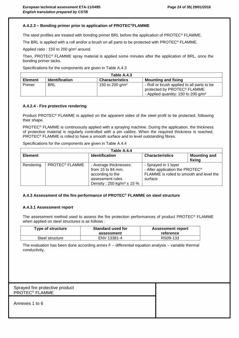
A.4.2.3 – Bonding primer prior to application of PROTEC®FLAMME
The steel profiles are treated with bonding primer BRL before the application of PROTEC® FLAMME.
The BRL is applied with a roll and/or a brush on all parts to be protected with PROTEC® FLAMME.
Applied ratio : 150 to 200 g/m² around.
Then, PROTEC® FLAMME spray material is applied some minutes after the application of BRL, once the bonding primer tacks.
Specifications for the components are given in Table A.4.3
Table A.4.3
Element Identification Characteristics Mounting and fixing
Primer BRL 150 to 200 g/m² - Roll or brush applied to all parts to be protected by PROTEC® FLAMME. - Applied quantity: 150 to 200 g/m²
A.4.2.4 - Fire protective rendering
Product PROTEC® FLAMME is applied on the apparent sides of the steel profil to be protected, following their shape.
PROTEC® FLAMME is continuously applied with a spraying machine. During the application, the thickness of protective material is regularly controlled with a pin calibre. When the required thickness is reached, PROTEC® FLAMME is rolled to have a smooth surface and to level outstanding fibres.
Specifications for the components are given in Table A.4.4
Table A.4.4
Element Identification Characteristics Mounting and fixing
Rendering PROTEC® FLAMME - Average thicknesses: from 15 to 84 mm, according to the assessment rules. Density : 250 kg/m³ ± 15 %
- Sprayed in 1 layer - After application the PROTEC® FLAMME is rolled to smooth and level the surface
A.4.3 Assessment of the fire performance of PROTEC® FLAMME on steel structure
A.4.3.1 Assessment report
The assessment method used to assess the fire protection performances of product PROTEC® FLAMME when applied on steel structures is as follows :
Type of structure Standard used for assessment
Assessment report reference
Steel structure ENV 13381-4 RS09-133
The evaluation has been done according annex F – differential equation analysis – variable thermal conductivity.
European technical assessment ETA-11/0495
English translation prepared by CSTB
Page 25 of 35| 29/01/2016
Sprayed fire protective product PROTEC® FLAMME
Annexes 1 to 6
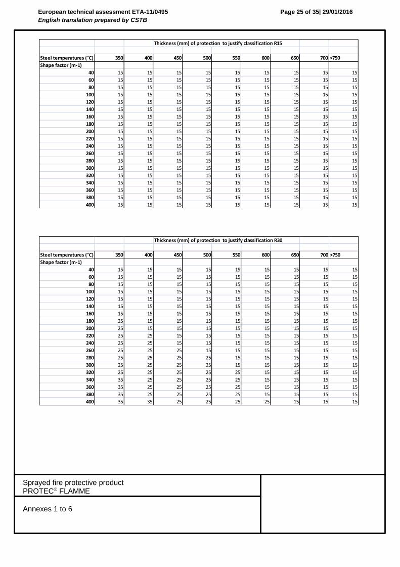
Thickness (mm) of protection to justify classification R15
Steel temperatures (°C) 350 400 450 500 550 600 650 700 >750
Shape factor (m-1)
40 15 15 15 15 15 15 15 15 15
60 15 15 15 15 15 15 15 15 15
80 15 15 15 15 15 15 15 15 15
100 15 15 15 15 15 15 15 15 15
120 15 15 15 15 15 15 15 15 15
140 15 15 15 15 15 15 15 15 15
160 15 15 15 15 15 15 15 15 15
180 15 15 15 15 15 15 15 15 15
200 15 15 15 15 15 15 15 15 15
220 15 15 15 15 15 15 15 15 15
240 15 15 15 15 15 15 15 15 15
260 15 15 15 15 15 15 15 15 15
280 15 15 15 15 15 15 15 15 15
300 15 15 15 15 15 15 15 15 15
320 15 15 15 15 15 15 15 15 15
340 15 15 15 15 15 15 15 15 15
360 15 15 15 15 15 15 15 15 15
380 15 15 15 15 15 15 15 15 15
400 15 15 15 15 15 15 15 15 15
Thickness (mm) of protection to justify classification R30
Steel temperatures (°C) 350 400 450 500 550 600 650 700 >750
Shape factor (m-1)
40 15 15 15 15 15 15 15 15 15
60 15 15 15 15 15 15 15 15 15
80 15 15 15 15 15 15 15 15 15
100 15 15 15 15 15 15 15 15 15
120 15 15 15 15 15 15 15 15 15
140 15 15 15 15 15 15 15 15 15
160 15 15 15 15 15 15 15 15 15
180 25 15 15 15 15 15 15 15 15
200 25 15 15 15 15 15 15 15 15
220 25 25 15 15 15 15 15 15 15
240 25 25 15 15 15 15 15 15 15
260 25 25 25 15 15 15 15 15 15
280 25 25 25 25 15 15 15 15 15
300 25 25 25 25 15 15 15 15 15
320 25 25 25 25 25 15 15 15 15
340 35 25 25 25 25 15 15 15 15
360 35 25 25 25 25 15 15 15 15
380 35 25 25 25 25 15 15 15 15
400 35 35 25 25 25 25 15 15 15
European technical assessment ETA-11/0495
English translation prepared by CSTB
Page 26 of 35| 29/01/2016
Sprayed fire protective product PROTEC® FLAMME
Annexes 1 to 6
Steel temperatures (°C) 350 400 450 500 550 600 650 700 >750
Shape factor (m-1)
40 15 15 15 15 15 15 15 15 15
60 15 15 15 15 15 15 15 15 15
80 25 25 15 15 15 15 15 15 15
100 25 25 25 25 15 15 15 15 15
120 35 25 25 25 25 15 15 15 15
140 35 35 25 25 25 25 25 15 15
160 35 35 35 25 25 25 25 15 15
180 45 35 35 35 25 25 25 25 15
200 45 45 35 35 25 25 25 25 15
220 45 45 35 35 35 25 25 25 25
240 55 45 45 35 35 35 25 25 25
260 55 45 45 35 35 35 25 25 25
280 55 45 45 45 35 35 35 25 25
300 55 55 45 45 35 35 35 25 25
320 55 55 45 45 35 35 35 35 25
340 55 55 45 45 45 35 35 35 25
360 65 55 55 45 45 35 35 35 25
380 65 55 55 45 45 45 35 35 25
400 65 55 55 45 45 45 35 35 25
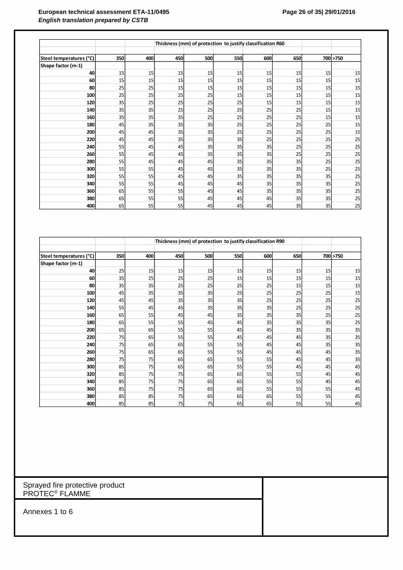
Thickness (mm) of protection to justify classification R60
Steel temperatures (°C) 350 400 450 500 550 600 650 700 >750
Shape factor (m-1)
40 25 15 15 15 15 15 15 15 15
60 35 25 25 25 15 15 15 15 15
80 35 35 25 25 25 25 15 15 15
100 45 35 35 35 25 25 25 25 15
120 45 45 35 35 35 25 25 25 25
140 55 45 45 35 35 35 25 25 25
160 65 55 45 45 35 35 35 25 25
180 65 55 55 45 45 35 35 35 25
200 65 65 55 55 45 45 35 35 35
220 75 65 55 55 45 45 45 35 35
240 75 65 65 55 55 45 45 35 35
260 75 65 65 55 55 45 45 45 35
280 75 75 65 65 55 55 45 45 35
300 85 75 65 65 55 55 45 45 45
320 85 75 75 65 65 55 55 45 45
340 85 75 75 65 65 55 55 45 45
360 85 75 75 65 65 55 55 55 45
380 85 85 75 65 65 65 55 55 45
400 85 85 75 75 65 65 55 55 45
Thickness (mm) of protection to justify classification R90
European technical assessment ETA-11/0495
English translation prepared by CSTB
Page 27 of 35| 29/01/2016
Sprayed fire protective product PROTEC® FLAMME
Annexes 1 to 6
Steel temperatures (°C) 350 400 450 500 550 600 650 700 >750
Shape factor (m-1)
40 35 25 25 25 25 15 15 15 15
60 45 35 35 25 25 25 25 25 15
80 55 45 45 35 35 35 25 25 25
100 65 55 45 45 35 35 35 25 25
120 65 65 55 45 45 45 35 35 25
140 75 65 65 55 55 45 45 35 35
160 85 75 65 65 55 45 45 45 35
180 85 75 75 65 55 55 45 45 45
200 85 85 75 65 65 55 55 45 45
220 85 75 75 65 65 55 55 45
240 85 85 75 65 65 55 55 45
260 85 75 75 65 65 55 55
280 85 85 75 65 65 55 55
300 85 85 75 75 65 65 55
320 85 75 75 65 65 55
340 85 85 75 75 65 55
360 85 85 75 75 65 65
380 85 75 75 65 65
400 85 85 75 75 65
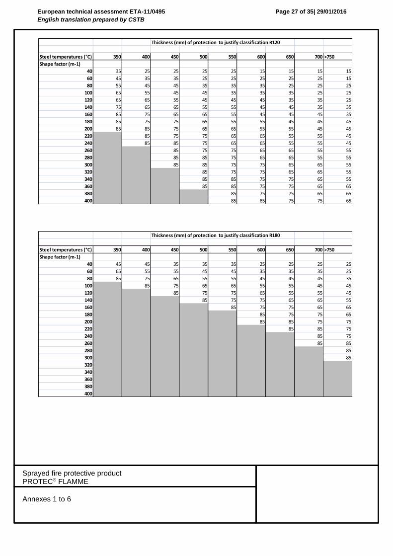
Thickness (mm) of protection to justify classification R120
Steel temperatures (°C) 350 400 450 500 550 600 650 700 >750
Shape factor (m-1)
40 45 45 35 35 35 25 25 25 25
60 65 55 55 45 45 35 35 35 25
80 85 75 65 55 55 45 45 45 35
100 85 75 65 65 55 55 45 45
120 85 75 75 65 55 55 45
140 85 75 75 65 65 55
160 85 75 75 65 65
180 85 75 75 65
200 85 85 75 75
220 85 85 75
240 85 75
260 85 85
280 85
300 85
320
340
360
380
400
Thickness (mm) of protection to justify classification R180
European technical assessment ETA-11/0495
English translation prepared by CSTB
Page 28 of 35| 29/01/2016
Sprayed fire protective product PROTEC® FLAMME
Annexes 1 to 6
Steel temperatures (°C) 350 400 450 500 550 600 650 700 >750
Shape factor (m-1)
40 65 55 55 45 45 35 35 35 25
60 85 75 65 55 55 45 45 45
80 85 75 65 65 55 55
100 85 85 75 65 65
120 85 75 75
140 85 75
160 85
180
200
220
240
260
280
300
320
340
360
380
400
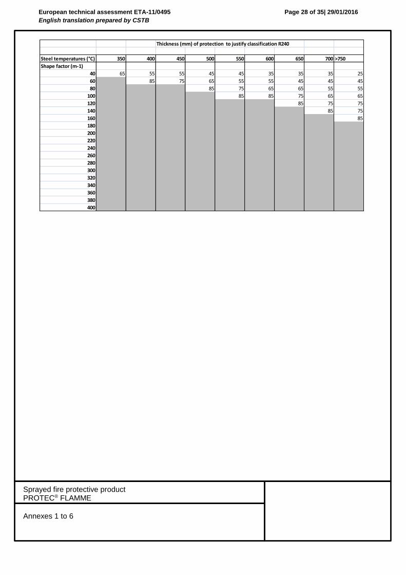
Thickness (mm) of protection to justify classification R240
European technical assessment ETA-11/0495
English translation prepared by CSTB
Page 29 of 35| 29/01/2016
Sprayed fire protective product PROTEC® FLAMME
Annexes 1 to 6
Annex 5 :
Specification and assessment of fire protection of a load bearing flat concrete profiled sheet composite elements assembly (intended use type 5) protected by PROTEC® FLAMME rendering
A.5.1 Classification
The assembly described in this annex has been tested and assessed according to ENV 13381-5 and classified in accordance with EN 13501-2.
The maximum duration of the exposure to the standard time temperature curve as defined in EN 1363-1, section 5.1.1, is 360 min depending on the type of concrete structures and the thickness of the PROTEC® FLAMME applied.
The assessment of the required thickness of PROTEC® FLAMME in function of type of profiled steel sheet and the exposure time for the characteristic steel sheet temperature rise to 350°C, the equivalent thickness of concrete and the insulation performances are given in clause A.5.3.
A.5.2 Installation requirements
A.5.2.1. Supporting structure
PROTEC® FLAMME is applicable on profiled steel sheets of composite slabs cast with dens concrete.
Specifications for the components are given in Table A.5.1.
Table A.5.1
Element Identification Characteristics Mounting and fixing
Profiled steel sheet
Trapezoïdal COFRAPLUS 60
- Thickness of steel sheet > 0,75 mm
- Width of the rib < 151 mm
- Height of the rib < 87 mm
- Surface shall be free of dust.
Concrete Concrete silicious aggregates
- Density 2330 kg/m³ ± 15 %
A.5.2.2 – Bonding primer prior to application of PROTEC® FLAMME
The steel sheet are treated with bonding primer BRL before the application of PROTEC® FLAMME.
The BRL is applied with a roll and/or a brush on all parts to be protected with PROTEC® FLAMME.
Applied ratio : 150 to 200 g/m² around.
Then, PROTEC® FLAMME spray material is applied some minutes after the application of BRL, once the bonding primer tacks.
European technical assessment ETA-11/0495
English translation prepared by CSTB
Page 30 of 35| 29/01/2016
Sprayed fire protective product PROTEC® FLAMME
Annexes 1 to 6
Specifications for the components are given in Table A.5.2
Table A.5.2
Element Identification Characteristics Mounting and fixing
Primer BRL 150 to 200 g/m² - Roll or brush applied to all parts to be protected by PROTEC® FLAMME.
- Applied quantity: 150 to 200 g/m²
A.5.2.3 - Fire protective rendering
Product PROTEC® FLAMME is applied on the apparent sides of the profiled steel sheet to be protected, following their shape.
PROTEC® FLAMME is continuously applied with a spraying machine. During the application, the thickness of protective material is regularly controlled with a pin calibre. When the required thickness is reached, PROTEC® FLAMME is rolled to have a smooth surface and to level outstanding fibres.
Specifications for the components are given in Table A.5.3
Table A.5.3
Element Identification Characteristics Mounting and fixing
Rendering PROTEC® FLAMME
- Average thicknesses: from 18 to 77 mm, according to the assessment rules.
Density : 250 kg/m³ ± 15 %
- Sprayed in 1 layer - After application the PROTEC® FLAMME is rolled to smooth and level the surface
A.5.3 Assessment of the fire performance of PROTEC® FLAMME on flat concrete profiled sheet composite elements assembly
A.5.3.1 Assessment report
The assessment method used to assess the fire protection performances of product PROTEC® FLAMME when applied on concrete structures is as follows :
Type of structure Standard used for assessment
Assessment report reference
Flat concrete profiled sheet ENV 13381-5 RS09-156
A.5.3.2 Time to reach 350°C in steel sheet
The duration to reach 350°C in steel sheet has been determined according to ENV 13381-5 chap 13.2 and are given in table A.5.4
Table A.5.4
Thickness of PROTEC® FLAMME Time to reach 350°C
18 mm 44 min
77 mm 111 min
European technical assessment ETA-11/0495
English translation prepared by CSTB
Page 31 of 35| 29/01/2016
Sprayed fire protective product PROTEC® FLAMME
Annexes 1 to 6
A.5.3.3 Equivalent thickness of concrete
Heff, Tr, He, Heq have been determined according to ENV 13381-5 chap 13.3 and are given in table A.5.5
Table A.5.5
Thickness of PROTEC® FLAMME Heff Tr He Heq
18 mm 83 mm 90 min 102 mm 19 mm
77 mm 220 min 167 mm 84 mm
A.5.3.4 Limiting exposition duration
The limiting exposition duration has been determined according to ENV 13381-5 chap 13.4 and are given in table A.5.6
Table A.5.6
Thickness of PROTEC® FLAMME Limiting exposition duration
18 mm 90 min
77 mm 220 min
European technical assessment ETA-11/0495
English translation prepared by CSTB
Page 32 of 35| 29/01/2016
Sprayed fire protective product PROTEC® FLAMME
Annexes 1 to 6
Annex 6 :
Specification and assessment of fire protection of a timber floor (intended use type 10) protected by PROTEC® FLAMME rendering
A.6.1 Classification
The assembly described in this annex has been tested and assessed according to EN 1365-2 and classified in accordance with EN 13501-2.
A.5.2 Installation requirements
A.6.2.1. Supporting structure
The supporting structure is a timber floor consisting of fir tree timber joists (minimum section 150 x 50 mm), spacing of 415 mm connected with fir tree cross members (minimum section 150 x 50 mm) spacing (maximum 2000 mm), and a fir tree floor (minimum section 70 (width) x 23 (thickness) mm) with tongue and groove, fastened to the timber joists.
A metallic lath NERGALTO NG1 in galvanised (Z275) steel (DX51D) fixed on the bottom of joists with staples installed every 150 mm.
The value longitudinal overlapping between two breadth is corresponding to one rib of the lath.
The average value transverse overlapping between two breadth is 410 mm.
Size of lath : 2510 mm (length) x 606 mm (width) x 0,3 mm (thickness).
Fasteners are made of resined galvanised steel (sizes : 25 mm (length) x 10,5 mm (width) x 1,5 mm (thickness)
The height of the cavity is minimum 150 mm.
The span is 4300 mm, the regular applied load is 150 kg/m².
A.6.2.2 - Fire protective rendering
Product PROTEC® FLAMME is applied directly on the metallic lath.
PROTEC® FLAMME is continuously applied with a spraying machine. During the application, the thickness of protective material is regularly controlled with a pin calibre. When the required thickness is reached, PROTEC® FLAMME is rolled to have a smooth surface and to level outstanding fibres.
Specifications for the components are given in Table A.6.1
Table A.6.1
Element Identification Characteristics Mounting and fixing
Rendering PROTEC® FLAMME - Average thicknesses: from 41 to 85 mm, according to the assessment rules.
Density : 250 kg/m³ ± 15 %
- Sprayed in 1 layer - After application the PROTEC® FLAMME is rolled to smooth and level the surface
European technical assessment ETA-11/0495
English translation prepared by CSTB
Page 33 of 35| 29/01/2016
Sprayed fire protective product PROTEC® FLAMME
Annexes 1 to 6
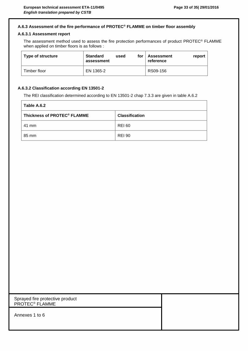
A.6.3 Assessment of the fire performance of PROTEC® FLAMME on timber floor assembly
A.6.3.1 Assessment report
The assessment method used to assess the fire protection performances of product PROTEC® FLAMME when applied on timber floors is as follows :
Type of structure Standard used for assessment
Assessment report reference
Timber floor EN 1365-2 RS09-156
A.6.3.2 Classification according EN 13501-2
The REI classification determined according to EN 13501-2 chap 7.3.3 are given in table A.6.2
Table A.6.2
Thickness of PROTEC® FLAMME Classification
41 mm REI 60
85 mm REI 90
European technical assessment ETA-11/0495
English translation prepared by CSTB
Page 34 of 35| 29/01/2016
Sprayed fire protective product PROTEC® FLAMME
Annex 7
Installation
Annex 7
Installation
4.2.1 – General The fire protection rendering must be installed according to the manufacturer’s instructions. It is the manufacturer’s responsibility to provide correct information about the application to the users. Minimum requirements for satisfactory installing of the product in respect of training, competence and experience are identified in the installation instructions of the manufacturer. On request of the applicator, the manufacturer may carry out a technical training on site for the use of the PROTEC® FLAMME product. 4.2.2 - Tool and equipment for application
Typical machines used to spray PROTEC® FLAMME are welded steel built and designed for the spraying of mineral fibers and low density pulverizable products. They usually comprise a supply hopper, a carding system, an air propulsion system, a water pump, and hoses to bring PROTEC® FLAMME and water to the spraying nozzle. 4.2.3 - Requirements for substrate 4.2.3.1 - Inspection of substrate Before application the substrate should be inspected and prepared. The inspection consists of the verification of the surfaces to be sprayed. They shall be free from oil, grease, incompatible primer (see below), lock down agent or of any other substance that will impair adhesion. 4.2.3.2 - Anti corrosion primers Corrosion protection primers acceptable for steel structures that have been a part of the test assemblies are : - short / medium alkyd primers family - two components epoxy family - hot dip galvanised steel 4.2.3.3 - Bonding agent Bonding primer for PROTEC® FLAMME is described in clause 1 4.2.4 – Additional bonding reinforcement For timber floors, a metallic lath shall be used. 4.2.5 - Environmental conditions during mixing, application and construction An air and substrate temperature of 5°C minimum shall be maintained for 24 hours prior to application, during application and for a minimum of 72 hours after application. Envisage an adequate ventilation to allow the product to dry after being sprayed. In closed area where the ventilation is not adequate, it is necessary to install a ventilation and air circulation device sufficient to obtain a renewing of air at least 1 to 3 times per hour, depending on sprayed thickness and room temperature. During winter time special considerations must be taken according to recommendations from the manufacturer. As given in § 2.1 the product is intended for semi-exposed conditions with no exposure to rain. The construction process may however result in the rendering being exposed to direct rain or leakages before the building envelope is closed. The resistance of the rendering to such short term exposure to rain has not been assessed within this ETA. It is therefore assumed that special provisions to temporarily protect the exposed rendering being subjected to rain are taken.
European technical assessment ETA-11/0495
English translation prepared by CSTB
Page 35 of 35| 29/01/2016
Sprayed fire protective product PROTEC® FLAMME
Annex 7
Installation
4.2.6 - Application of rendering Depending on the nature of the substrate, PROTEC® FLAMME is to be applied on a proper primer or expanded metal rib lath. The primer must be tacky. PROTEC® FLAMME should be sprayed in a coat of regular thickness, depending on the requested thickness as follows: Total thickness between 15 and 88mm : a coat of regular thickness (the nearest to the requested thickness as possible ) is sprayed. After checking the thickness, the coat is completed up to the requested thickness. After application, PROTEC® FLAMME is rolled (smoothed out with a roller). 4.2.7 - Site tests The adhesion of the dry rendering to the substrate should be tested on site. A suitable method for site measurement is given in annex 2. It is based on EGOLF method SM/5. The thickness should be measured at a frequency sufficient to determine the mean and minimum thickness. A suitable method for thickness measurement is given in ETAG 018-3, clause 5.0.2 (for non-fire tests). The density of the rendering should be measured and be within the tolerances specified in table 1.1. A suitable method for density measurement is given in ETAG 018-3, clause 5.0.2 except that the number of samples may be reduced to an appropriate level. Hairline cracks in the dry rendering are not acceptable. 4.2.8 - Surface treatments and protection The resistance to mechanical impact from hard and soft bodies have not been assessed. The use of the rendering is therefore limited to applications where the rendering is protected from such impacts. The accessible structure exposed to friction or impact related to the activity on site should be covered with adapted protection depending on the site configuration. The protection is to be independent from the PROTEC®
FLAMME coating. Rolling surface of the rendering to produce a more regular finish than that achievable by initial application is covered by this ETA. The vapour permeability of the product has not been assessed. Indications to the manufacturer and supplier Packaging, transport and storage PROTEC® FLAMME is packaged in plastic bags weighing 25kg on pallet of 24 bags. The product shall be stored away from weather exposure or wet surface. Stock of material is to be rotated and used before its expiration date indicated on the bags (12 months from date of fabrication). Use, maintenance, repair The product, installed according to this ETA and manufacturer specifications does not require any maintenance. Limited damages of PROTEC® FLAMME can be repaired. The damaged areas shall be carefully cleaned with a knife, cutter or trowel through the whole applied thickness, down to the support. An additional zone of 700mm all around the damaged areas shall be cut at an angle so as to create a conic shape centred on the damaged areas. Dust and particles generated by this operation shall be carefully eliminated. Before repairing, the cleared substrate shall be treated with the primer BRL. The bonding primer is applied with a brush. When the bonding primer starts to tack, PROTEC® FLAMME shall be sprayed with a spraying machine, in such a way that the opening is completely filled up and the surface of the repaired area is smooth and flush with the surrounding PROTEC® FLAMME after compacting manually with a roll to level outstanding fibers.