Embed Size (px)
Citation preview
Pour personnaliser « nom
événement et auteur » :
« Insertion / En-tête et pied
de page »
Personnaliser la zone de de
pied de page
Cliquer sur appliquer partout
RECENT MODELLING
ADVANCES FOR ULTRASONIC
TOFD INSPECTIONS
Michel DARMON1, Adrien FERRAND1, Vincent DORVAL1, Sylvain CHATILLON1
CEA LIST, Gif-sur-Yvette, France
QNDE | July 2014
Pour personnaliser « nom
événement et auteur » :
« Insertion / En-tête et pied
de page »
Personnaliser la zone de de
pied de page
Cliquer sur appliquer partout
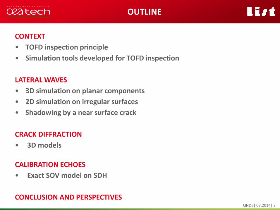
CONTEXT
• TOFD inspection principle
• Simulation tools developed for TOFD inspection
LATERAL WAVES
• 3D simulation on planar components
• 2D simulation on irregular surfaces
• Shadowing by a near surface crack
CRACK DIFFRACTION
• 3D models
CALIBRATION ECHOES
• Exact SOV model on SDH
CONCLUSION AND PERSPECTIVES
OUTLINE
QNDE| 07.2014| 3
CONTEXT
Pour personnaliser « nom
événement et auteur » :
« Insertion / En-tête et pied
de page »
Personnaliser la zone de de
pied de page
Cliquer sur appliquer partout
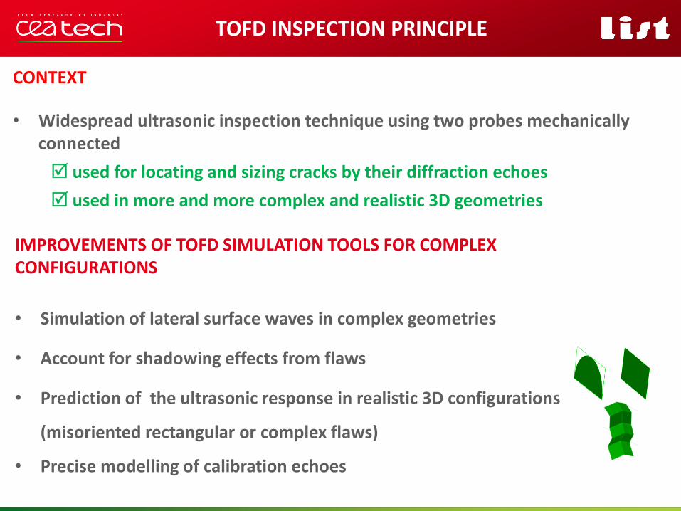
CONTEXT
• Widespread ultrasonic inspection technique using two probes mechanically connected
used for locating and sizing cracks by their diffraction echoes
used in more and more complex and realistic 3D geometries
TOFD INSPECTION PRINCIPLE
Pour personnaliser « nom
événement et auteur » :
« Insertion / En-tête et pied
de page »
Personnaliser la zone de de
pied de page
Cliquer sur appliquer partout
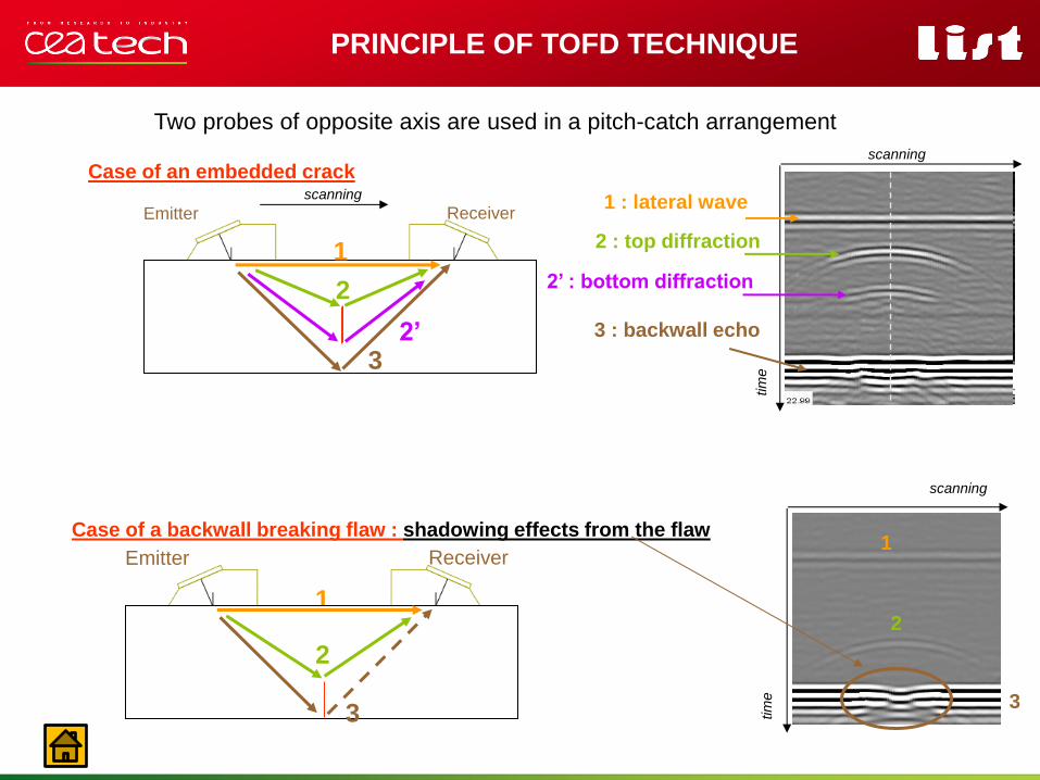
Two probes of opposite axis are used in a pitch-catch arrangement
Emitter Receiver
Case of an embedded crack
1
2’ 3
2
scanning
PRINCIPLE OF TOFD TECHNIQUE
scanning
tim
e
Emitter Receiver
1
2
3
Case of a backwall breaking flaw : shadowing effects from the flaw 1
2
3
2’ : bottom diffraction
scanning
tim
e
1 : lateral wave
3 : backwall echo
2 : top diffraction
Pour personnaliser « nom
événement et auteur » :
« Insertion / En-tête et pied
de page »
Personnaliser la zone de de
pied de page
Cliquer sur appliquer partout
CONTEXT
• Widespread ultrasonic inspection technique using two probes mechanically connected
used for locating and sizing cracks by their diffraction echoes
used in more and more complex and realistic 3D geometries
TOFD INSPECTION PRINCIPLE
IMPROVEMENTS OF TOFD SIMULATION TOOLS FOR COMPLEX CONFIGURATIONS
• Simulation of lateral surface waves in complex geometries
• Account for shadowing effects from flaws
• Prediction of the ultrasonic response in realistic 3D configurations
(misoriented rectangular or complex flaws)
• Precise modelling of calibration echoes
LATERAL WAVES
Pour personnaliser « nom
événement et auteur » :
« Insertion / En-tête et pied
de page »
Personnaliser la zone de de
pied de page
Cliquer sur appliquer partout
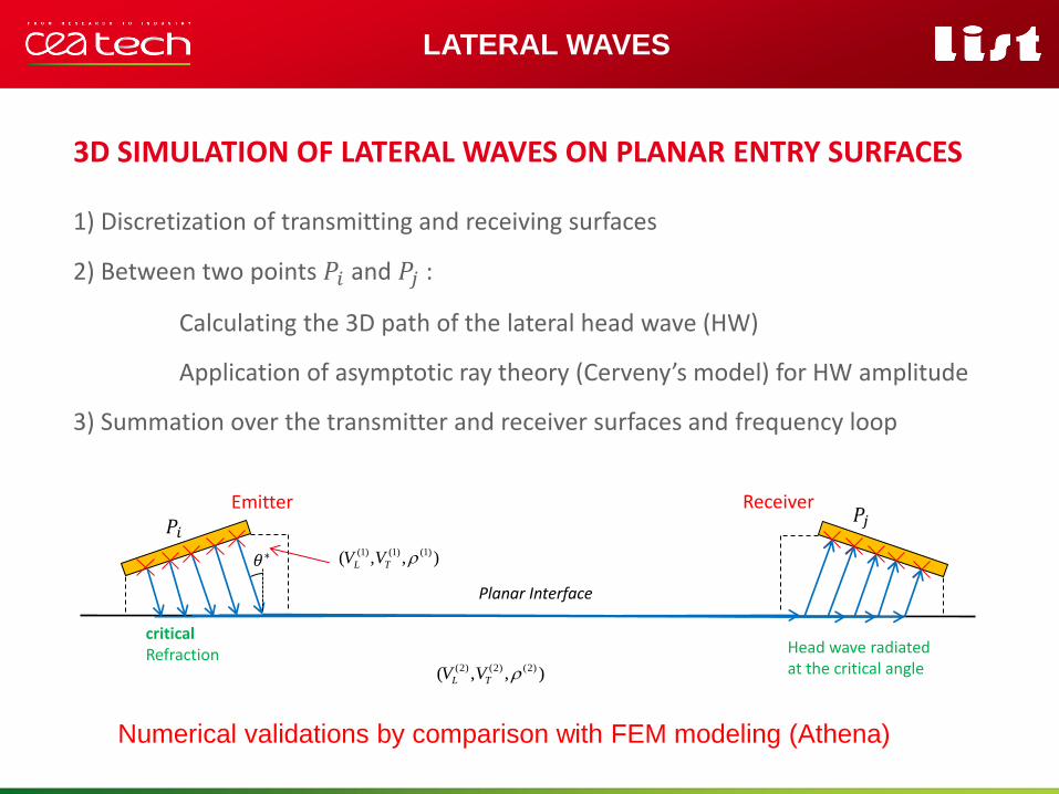
3D SIMULATION OF LATERAL WAVES ON PLANAR ENTRY SURFACES
LATERAL WAVES
critical Refraction Head wave radiated
at the critical angle
Planar Interface
Emitter Receiver
(1) (1) (1)( , , )L TV V
(2) (2) (2)( , , )L TV V
𝑃𝑖 𝑃𝑗
𝜃∗
1) Discretization of transmitting and receiving surfaces
2) Between two points 𝑃𝑖 and 𝑃𝑗 :
Calculating the 3D path of the lateral head wave (HW)
Application of asymptotic ray theory (Cerveny’s model) for HW amplitude
3) Summation over the transmitter and receiver surfaces and frequency loop
Numerical validations by comparison with FEM modeling (Athena)
Pour personnaliser « nom
événement et auteur » :
« Insertion / En-tête et pied
de page »
Personnaliser la zone de de
pied de page
Cliquer sur appliquer partout
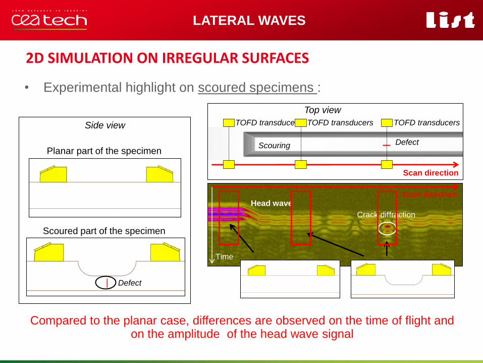
2D SIMULATION ON IRREGULAR SURFACES
LATERAL WAVES
• Experimental highlight on scoured specimens :
Head wave
Crack diffraction
Scan direction
Time
Scouring Defect
TOFD transducers
Scan direction
Top view
Compared to the planar case, differences are observed on the time of flight and on the amplitude of the head wave signal
Side view
Planar part of the specimen
Scoured part of the specimen
Defect
TOFD transducers TOFD transducers
Pour personnaliser « nom
événement et auteur » :
« Insertion / En-tête et pied
de page »
Personnaliser la zone de de
pied de page
Cliquer sur appliquer partout
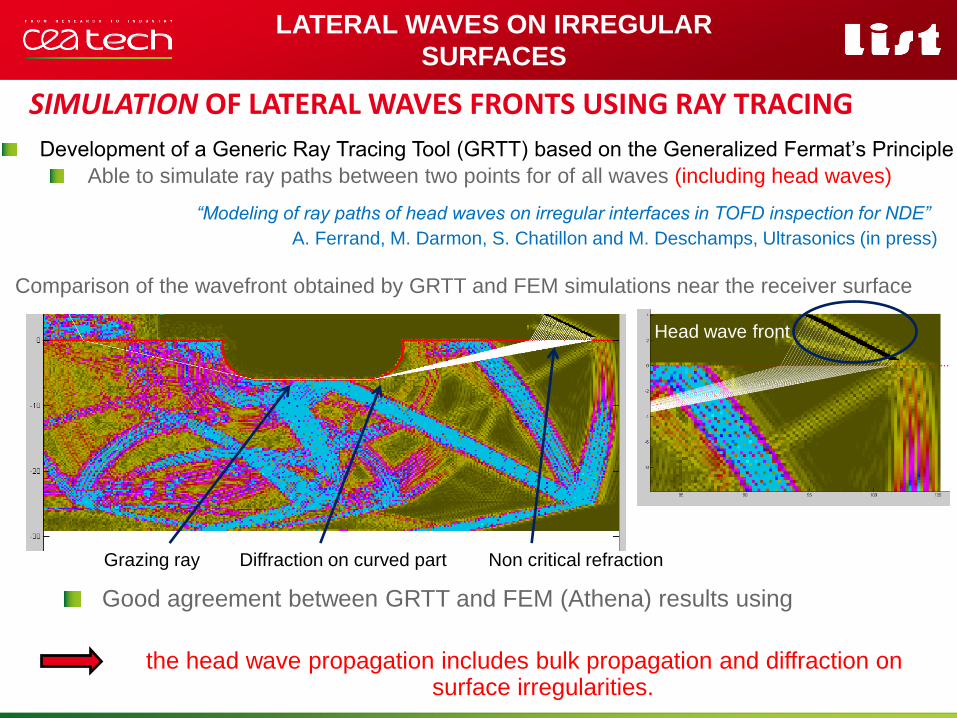
SIMULATION OF LATERAL WAVES FRONTS USING RAY TRACING
Comparison of the wavefront obtained by GRTT and FEM simulations near the receiver surface
Grazing ray Diffraction on curved part Non critical refraction
Good agreement between GRTT and FEM (Athena) results using
the head wave propagation includes bulk propagation and diffraction on surface irregularities.
LATERAL WAVES ON IRREGULAR
SURFACES
Development of a Generic Ray Tracing Tool (GRTT) based on the Generalized Fermat’s Principle
Able to simulate ray paths between two points for of all waves (including head waves)
“Modeling of ray paths of head waves on irregular interfaces in TOFD inspection for NDE”
A. Ferrand, M. Darmon, S. Chatillon and M. Deschamps, Ultrasonics (in press)
Head wave front
Pour personnaliser « nom
événement et auteur » :
« Insertion / En-tête et pied
de page »
Personnaliser la zone de de
pied de page
Cliquer sur appliquer partout
LATERAL WAVES ON IRREGULAR
SURFACES
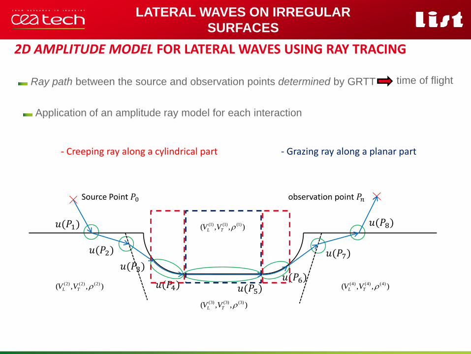
2D AMPLITUDE MODEL FOR LATERAL WAVES USING RAY TRACING
SOUTENANCE DE THÈSE | ADRIEN FERRAND | 11
1
Source Point 𝑃0 observation point 𝑃𝑛
(1) (1) (1)( , , )L TV V
(2) (2) (2)( , , )L TV V
(3) (3) (3)( , , )L TV V
(4) (4) (4)( , , )L TV V
𝑢(𝑃1)
𝑢(𝑃2)
𝑢(𝑃3)
𝑢(𝑃4) 𝑢(𝑃5) 𝑢(𝑃6)
𝑢(𝑃7)
𝑢(𝑃8)
- Creeping ray along a cylindrical part - Grazing ray along a planar part
Application of an amplitude ray model for each interaction
Ray path between the source and observation points determined by GRTT time of flight
Pour personnaliser « nom
événement et auteur » :
« Insertion / En-tête et pied
de page »
Personnaliser la zone de de
pied de page
Cliquer sur appliquer partout
LATERAL WAVES ON IRREGULAR
SURFACES
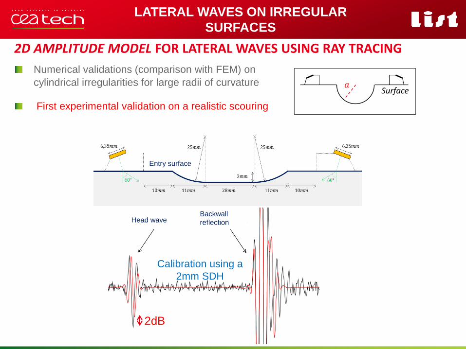
2D AMPLITUDE MODEL FOR LATERAL WAVES USING RAY TRACING
Numerical validations (comparison with FEM) on
cylindrical irregularities for large radii of curvature 𝑎 Surface
2dB
Entry surface
Head wave Backwall
reflection
First experimental validation on a realistic scouring
Calibration using a
2mm SDH
Pour personnaliser « nom
événement et auteur » :
« Insertion / En-tête et pied
de page »
Personnaliser la zone de de
pied de page
Cliquer sur appliquer partout
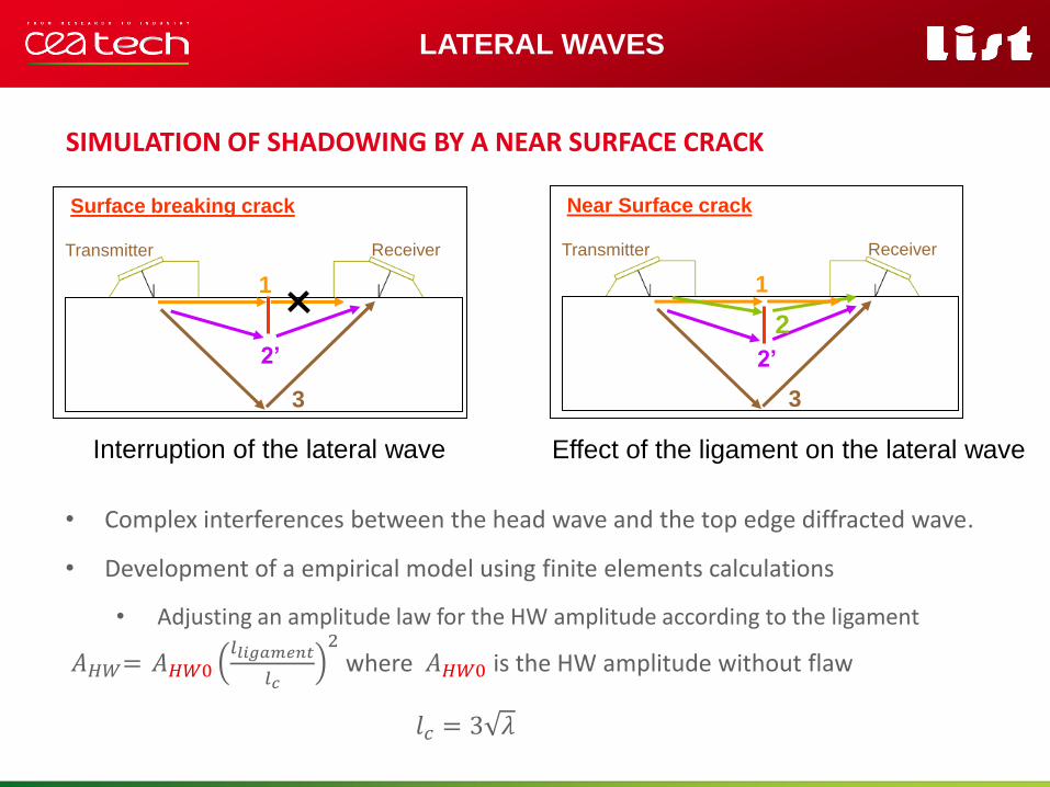
• Complex interferences between the head wave and the top edge diffracted wave.
• Development of a empirical model using finite elements calculations
• Adjusting an amplitude law for the HW amplitude according to the ligament
𝐴𝐻𝑊= 𝐴𝐻𝑊0𝑙𝑙𝑖𝑔𝑎𝑚𝑒𝑛𝑡
𝑙𝑐
2
where 𝐴𝐻𝑊0 is the HW amplitude without flaw
𝑙𝑐 = 3 𝜆
SIMULATION OF SHADOWING BY A NEAR SURFACE CRACK
LATERAL WAVES
Transmitter Receiver
Surface breaking crack
1
2’
3
Interruption of the lateral wave Effect of the ligament on the lateral wave
Transmitter Receiver
Near Surface crack
1
2’
3
2
Pour personnaliser « nom
événement et auteur » :
« Insertion / En-tête et pied
de page »
Personnaliser la zone de de
pied de page
Cliquer sur appliquer partout
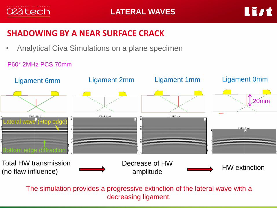
Ligament 6mm Ligament 2mm Ligament 1mm
SHADOWING BY A NEAR SURFACE CRACK
• Analytical Civa Simulations on a plane specimen
LATERAL WAVES
The simulation provides a progressive extinction of the lateral wave with a
decreasing ligament.
Total HW transmission
(no flaw influence) Decrease of HW
amplitude
Ligament 0mm
P60° 2MHz PCS 70mm
HW extinction
Lateral wave (+top edge)
Bottom edge diffraction
20mm
CRACK DIFFRACTION
Pour personnaliser « nom
événement et auteur » :
« Insertion / En-tête et pied
de page »
Personnaliser la zone de de
pied de page
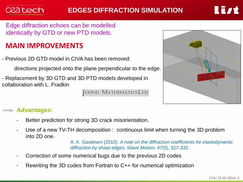
Cliquer sur appliquer partout MAIN IMPROVEMENTS
CFA| 23.04.2014| 3
EDGES DIFFRACTION SIMULATION
- Previous 2D GTD model in CIVA has been removed:
directions projected onto the plane perpendicular to the edge.
- Replacement by 3D GTD and 3D PTD models developed in
collaboration with L. Fradkin
Advantages:
- Better prediction for strong 3D crack misorientation.
- Use of a new TV-TH decomposition : continuous limit when turning the 3D problem
into 2D one.
- Correction of some numerical bugs due to the previous 2D codes
- Rewriting the 3D codes from Fortran to C++ for numerical optimization
Edge diffraction echoes can be modelled
identically by GTD or new PTD models.
A. K. Gautesen (2010). A note on the diffraction coefficients for elastodynamic
diffraction by sharp edges. Wave Motion, 47(5), 327-332.
td. athematics ound LM
Pour personnaliser « nom
événement et auteur » :
« Insertion / En-tête et pied
de page »
Personnaliser la zone de de
pied de page
Cliquer sur appliquer partout
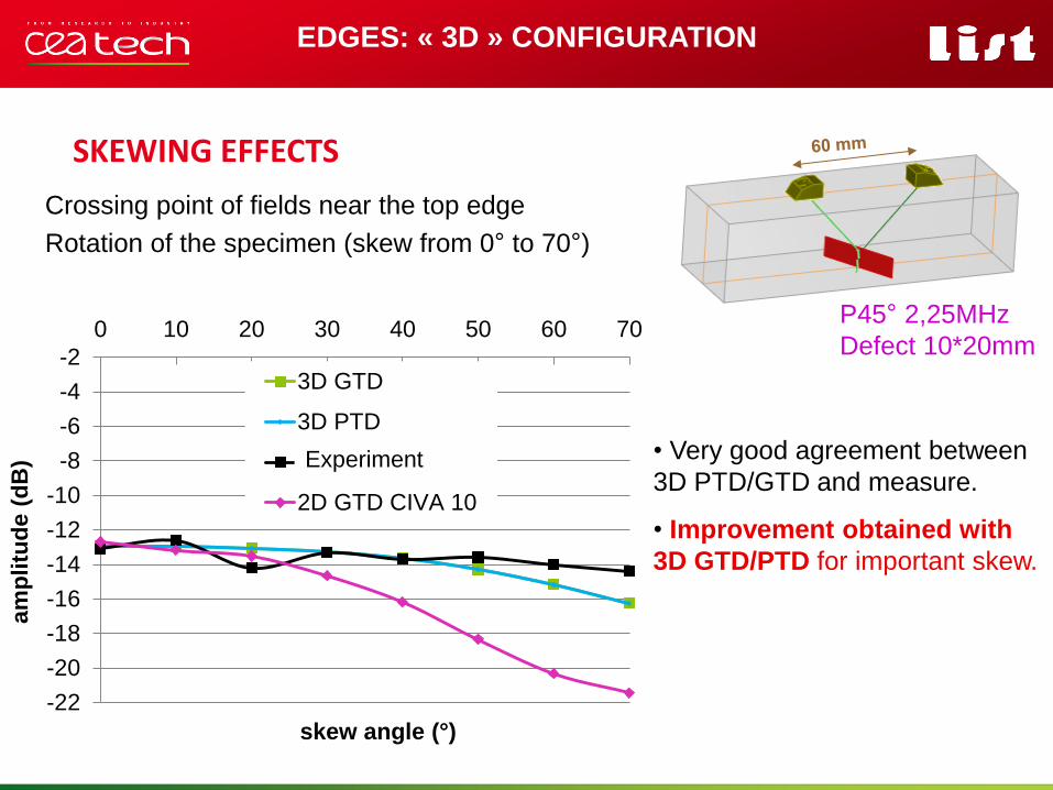
SKEWING EFFECTS
EDGES: « 3D » CONFIGURATION
• Very good agreement between
3D PTD/GTD and measure.
• Improvement obtained with
3D GTD/PTD for important skew.
Crossing point of fields near the top edge
Rotation of the specimen (skew from 0° to 70°)
-22
-20
-18
-16
-14
-12
-10
-8
-6
-4
-2
0 10 20 30 40 50 60 70
am
plitu
de (
dB
)
skew angle (°)
3D GTD
3D PTD
Experience
2D GTD CIVA 10
P45° 2,25MHz
Defect 10*20mm
Experiment
Pour personnaliser « nom
événement et auteur » :
« Insertion / En-tête et pied
de page »
Personnaliser la zone de de
pied de page
Cliquer sur appliquer partout
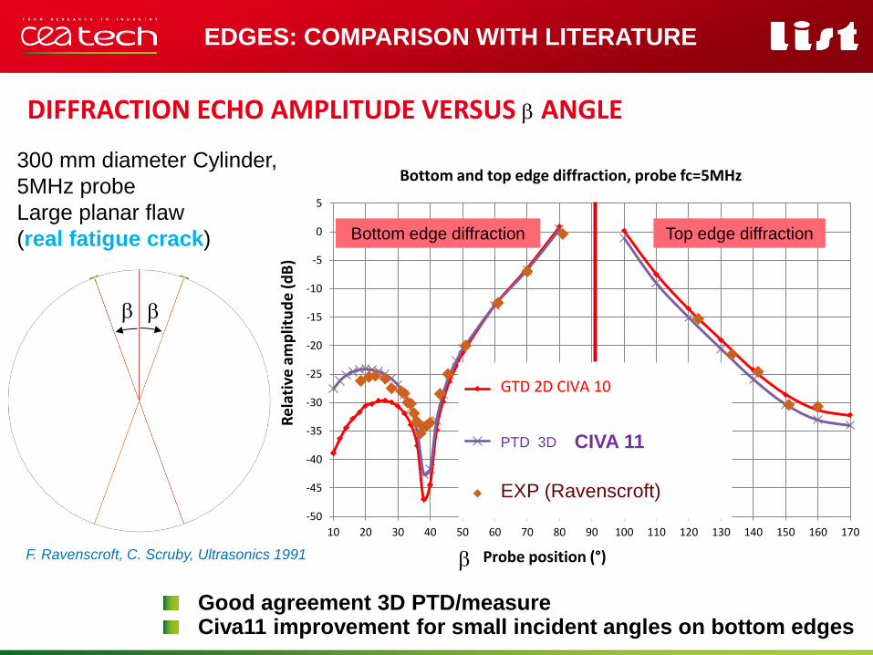
DIFFRACTION ECHO AMPLITUDE VERSUS b ANGLE
EDGES: COMPARISON WITH LITERATURE
300 mm diameter Cylinder,
5MHz probe
Large planar flaw
(real fatigue crack)
b
-50
-45
-40
-35
-30
-25
-20
-15
-10
-5
0
5
10 20 30 40 50 60 70 80 90 100 110 120 130 140 150 160 170
Re
lati
ve a
mp
litu
de
(d
B)
Probe position (°)
Bottom and top edge diffraction, probe fc=5MHz
Civa10 2D-2D (crack aperture=0mm)
Kirchoff GTD dev 17-10-12 (2D-2D)
Exp
GTD 2D CIVA 10
b
b
3D PTD 3D
Good agreement 3D PTD/measure Civa11 improvement for small incident angles on bottom edges
Bottom edge diffraction Top edge diffraction
CIVA 11
EXP (Ravenscroft)
F. Ravenscroft, C. Scruby, Ultrasonics 1991
SIMULATION OF THE CALIBRATION ON SDH
Pour personnaliser « nom
événement et auteur » :
« Insertion / En-tête et pied
de page »
Personnaliser la zone de de
pied de page
Cliquer sur appliquer partout
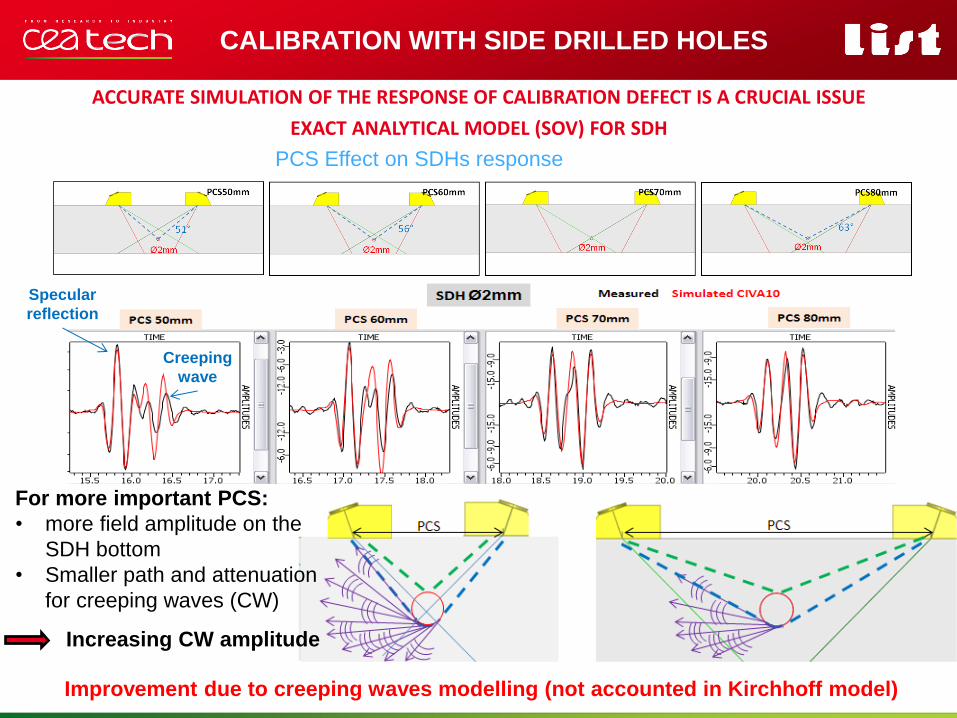
CALIBRATION WITH SIDE DRILLED HOLES
ACCURATE SIMULATION OF THE RESPONSE OF CALIBRATION DEFECT IS A CRUCIAL ISSUE
PCS Effect on SDHs response
Improvement due to creeping waves modelling (not accounted in Kirchhoff model)
For more important PCS:
• more field amplitude on the
SDH bottom
• Smaller path and attenuation
for creeping waves (CW)
Increasing CW amplitude
Specular
reflection
Creeping
wave
EXACT ANALYTICAL MODEL (SOV) FOR SDH
CONCLUSION AND PERSPECTIVES
Pour personnaliser « nom
événement et auteur » :
« Insertion / En-tête et pied
de page »
Personnaliser la zone de de
pied de page
Cliquer sur appliquer partout
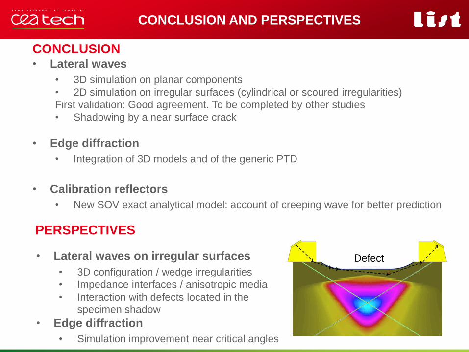
CONCLUSION AND PERSPECTIVES
CONCLUSION • Lateral waves
• 3D simulation on planar components
• 2D simulation on irregular surfaces (cylindrical or scoured irregularities)
First validation: Good agreement. To be completed by other studies
• Shadowing by a near surface crack
• Edge diffraction
• Integration of 3D models and of the generic PTD
• Calibration reflectors
• New SOV exact analytical model: account of creeping wave for better prediction
PERSPECTIVES
• Lateral waves on irregular surfaces
• 3D configuration / wedge irregularities
• Impedance interfaces / anisotropic media
• Interaction with defects located in the
specimen shadow
• Edge diffraction
• Simulation improvement near critical angles
Defect
Pour personnaliser « nom
événement et auteur » :
« Insertion / En-tête et pied
de page »
Personnaliser la zone de de
pied de page
Cliquer sur appliquer partout
Thank you for your attention
QNDE 2014 - SESSION 34 | JULY 25, 2013