Embed Size (px)
Citation preview
Université du Québec
Institut national de la recherche scientifique
Energie Materiaus télécommunications
ANTENNES AUX ONDES MILLIMÉTRIQUES AVEC FAISCEAU INCLINÉ
EN UTILISANT DES STRUCTURES MÉTAMATÉRIAUX
Par:
Abdolmehdi Dadgarpour
Proposition du jury d‟évaluation
Directeur de recherche : Prof. Tayeb A. Denidni
INRS-EMT
Examinateur interne et président du jury : Prof. Serioja Tatu INRS-EMT
Examinateur externe : Prof.Ahmed A.Kishk
Concordia University
Examinateur externe : Prof. Jean-Jacques.Laurin
École Polytechnique de Montréal
© Copyright by Abdolmehdi Dadgarpour, 2015
ii
Université du Québec
Institut national de la recherche scientifique
Energie Materiaus télécommunications
MILLIMETER-WAVE ANTENNA WITH BEAM-TILTING CAPABILITY
USING METAMATERIALS
By:
Abdolmehdi Dadgarpour
A dissertation Submitted in partial fulfillment of the requirements for the degree of
Doctor of Philosophy (Ph.D) in Telecommunications
Evaluation Jury
Research Director Prof. Tayeb A. Denidni
INRS-EMT
Internal examiner and Jury Prof. Serioja Tatu INRS-EMT
External examiner Prof.Ahmed A.Kishk
Concordia University
External examiner Prof. Jean-Jacques.Laurin
École Polytechnique de Montréal
© Copyright by Abdolmehdi Dadgarpour, 2015

iii
Dedication
This thesis is dedicated to my wife Naeemeh

iv
TABLE OF CONTENTS
LIST OF TABLES .............................................................................................................. ix
LIST OF FIGURES ............................................................................................................ x
ABSTRACT ...................................................................................................................... xxi
ACKNOWLEDGMENTS .............................................................................................. xxiv
Chapter 1 INTRODUCTION ......................................................................................... 1
1.1 Background and Motivation ...................................................................................... 1
1.2 Dissertation Outline ................................................................................................... 6
Chapter 2 Beam titlting antenna using metamaterial loading ....................................... 11
2.1 Introduction .............................................................................................................. 11
2.1.1 Beam Tilting Mechanism .................................................................................. 12
2.1.2 Metamaterial Unit-cell ...................................................................................... 14
2.1.3 BOW TIE ANTENNA WITH IML .................................................................. 18
2.1.4 PARAMETRIC STUDY .................................................................................. 21
2.1.5 Experimental Results ........................................................................................ 23
2.1.6 Conclusion ........................................................................................................ 26
Chapter 3 Radiation Beam Tilting of End-Fire Antenna with Meta-Surface ............... 28
3.1 Introduction .............................................................................................................. 28
3.2 Beam Tilting Approach ............................................................................................ 29
3.3 Bow-Tie Antenna with Array of SRR Unit-Cells .................................................... 32
3.4 Experimental Results ............................................................................................... 34
3.5 Conclusion ............................................................................................................... 36
Chapter 4 Enhancement of tilted beam in elevation plane for planar End-fire antennas
using artificial dielectric medium ...................................................................................... 37
4.1 Introduction .............................................................................................................. 37

v
4.2 Bow-tie Antenna ...................................................................................................... 39
4.3 Beam Tilting Mechanism ......................................................................................... 40
4.4 Metamaterial Unit-cell ............................................................................................. 42
4.5 Bow-Tie Antenna with DGR Unit-Cell ................................................................... 44
4.6 Parametric Study ...................................................................................................... 48
4.7 Experimental Results ............................................................................................... 51
4.8 Electronic Beam switching in the Elevation plane .................................................. 55
4.1 Conclusion ............................................................................................................... 57
Chapter 5 Millimeter-wave High-Gain SIW End-fire Bow-tie Antenna ..................... 58
5.1 Introduction .............................................................................................................. 58
5.2 Antenna Design ........................................................................................................ 60
5.3 The Effect of bow-tie radiator tilt angle................................................................... 62
5.4 The Effect of DGR loading ...................................................................................... 63
5.5 ZIM Unit-Cell .......................................................................................................... 66
5.6 Antenna with Array of ZIM Unit-Cell ..................................................................... 68
5.7 The Experimental Results ........................................................................................ 70
5.8 Conclusion ............................................................................................................... 75
Chapter 6 Beam Deflection Using Gradient refractive index media for 60 GHz end-
fire antenna 76
6.1 Introduction .............................................................................................................. 76
6.2 Beam deflection technique ....................................................................................... 77
6.3 Metamaterial Unit-Cell ............................................................................................ 80
6.4 Single Dipole Antenna with GRIM unit-cell ........................................................... 84
6.5 Parametric Study ...................................................................................................... 86
6.6 Experimental Results ............................................................................................... 88

vi
6.7 Double Feed Antenna with 5x4 array of GRIM ...................................................... 90
6.8 Fourth-Feed Antenna with GRIM array .................................................................. 94
6.9 Conclusion ............................................................................................................... 96
Chapter 7 Improvement of Gain and elevation tilt angle using metamaterial loading for
millimeter-wave application .............................................................................................. 97
7.1 Introduction .............................................................................................................. 97
7.2 Mechanism of Beam tilting ...................................................................................... 99
7.3 Beam Deflection on a single Dipole Antenna ........................................................ 103
7.4 Parametric Study .................................................................................................... 104
7.5 Beam Switching Network in the elevation plane ................................................... 105
7.6 Two Dimensional Beam Tilting ............................................................................. 107
7.7 Experimental Results ............................................................................................. 109
7.8 Conclusion ............................................................................................................. 112
Chapter 8 One and two dimensional Beam scanning antenna for millimeter-wave
mimo applications ............................................................................................................ 113
8.1 Introduction ............................................................................................................ 113
8.2 Mechanism of Beam scanning ............................................................................... 115
8.3 Beam Forming with a single antenna ..................................................................... 120
8.4 Parametric Study .................................................................................................... 122
8.5 Beam Switching Network In the Azimuth plane ................................................... 126
8.6 Two-Dimensional Beam Tilting ............................................................................ 127
8.7 Experimental Results ............................................................................................. 131
8.8 Conclusion ............................................................................................................. 137
Chapter 9 Dual beam end-fire antenna for 60 GHz applications realized by modifying
the permittivity of the dielectric slab ............................................................................... 138
9.1 Introduction ............................................................................................................ 138

vii
9.2 Mechanism of Dual Beam ..................................................................................... 140
9.3 Dual-Beam Radiation Pattern In the Azimuth plane ............................................. 143
9.4 Experimental Results ............................................................................................. 148
9.5 Conclusion ............................................................................................................. 151
Chapter 10 Conclusion and feauture work ................................................................... 152
10.1 Conclusion ........................................................................................................... 152
10.2 Future work .......................................................................................................... 154
Chapter 11 Resume ........................................................................................................ 155
11.1 Introduction .......................................................................................................... 155
11.2 Antenne à inclinaison de faisceau en utilisant des métamatériaux ...................... 157
11.2.1 Mécanisme de l‟Inclinaison de Faisceau ...................................................... 158
11.2.2 La Cellule Unitaireen métamatériau ............................................................. 159
11.2.3 L‟antenne en forme de nœud papillon avec la cellule unitaire en métamatériau
.................................................................................................................................. 160
11.3 L‟antenne nœud papillon avec une cellule unitaire DGR ................................... 162
11.4 L‟antenne nœud papillon à gain élevé en ondes millimétriques alimentée par un
guide d‟onde intégré au substrat .................................................................................. 164
11.5 La déviation du faisceau en utilisant un milieu à gradient d‟indice de réfraction
pour l‟antenne à rayonnement longitudinal à 60 GHz ................................................. 169
11.6 L‟inclinaison de faisceau à deux dimensions (bidimensionnelle) ....................... 171
11.7 L‟antenne au balayage à faisceau monodimensionnel et bidimensionnel pour les
applications MIMO en onde millimétrique .................................................................. 174
11.7.1 Le balayage de faisceau bidimensionnel ....................................................... 176
11.8 Le diagramme du rayonnement à double faisceau dans le plan azimutal ............ 178
11.9 Conclusion et travaux à venir .............................................................................. 180
11.9.1 Travaux Futures ............................................................................................ 182

viii
Refrences .......................................................................................................................... 184

ix
LIST OF TABLES
Table 2-1: The effect of IML on antenna performance ..................................................... 23
Table 2-2: Measured peak gain of antenna at different scan angles .................................. 25
Table 4-1: The effect of DGR unit-cells on the antenna performance ............................... 50
Table 4-2: Measured peak gain of antenna at different scanned angles ............................ 54
Table 5-1: Measured and simulated gain of the proposed tilted bow-tie antenna at various
frequencies ......................................................................................................................... 75
Table 6-1: Dimensions of GRIM unit-cell of various sizes ............................................... 82
Table 6-2: Measured peak gain and efficiency of double feed GRIM antenna ................. 94
Table 7-1: Metamaterial unit-cells (dimensions in millimeter) ....................................... 101
Table 8-1: Measured and simulated peak gain of the proposed MNZ dipole antenna at
beam scan angle of 34 degrees when port 1 is excited. ................................................... 134

x
LIST OF FIGURES
Figure 1-1: Configuration of the base-station antenna which is integrated by 1x4 EBG
dipole antenna arrays to obtain a down tilt under horizon to cover the cell [1]. .................. 1
Figure 1-2: Homogenous metamaterial unit-cell comprised of DSR and wire as a double
negative metamaterial region [2] ......................................................................................... 3
Figure 1-3: Leaky wave antenna realized by left handed metamaterial unit-cells [3] ......... 4
Figure 1-4: Electric resonance metamaterial unit-cell integrated by varator diode for beam
steering applications [4]. ...................................................................................................... 4
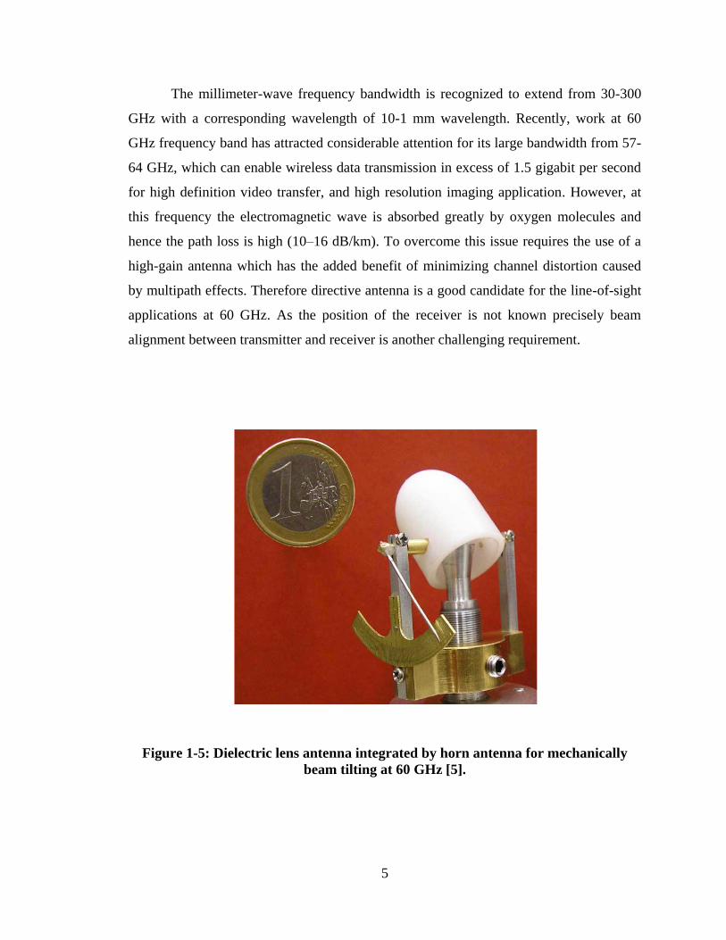
Figure 1-5: Dielectric lens antenna integrated by horn antenna for mechanically beam
tilting at 60 GHz [5]. ............................................................................................................ 5
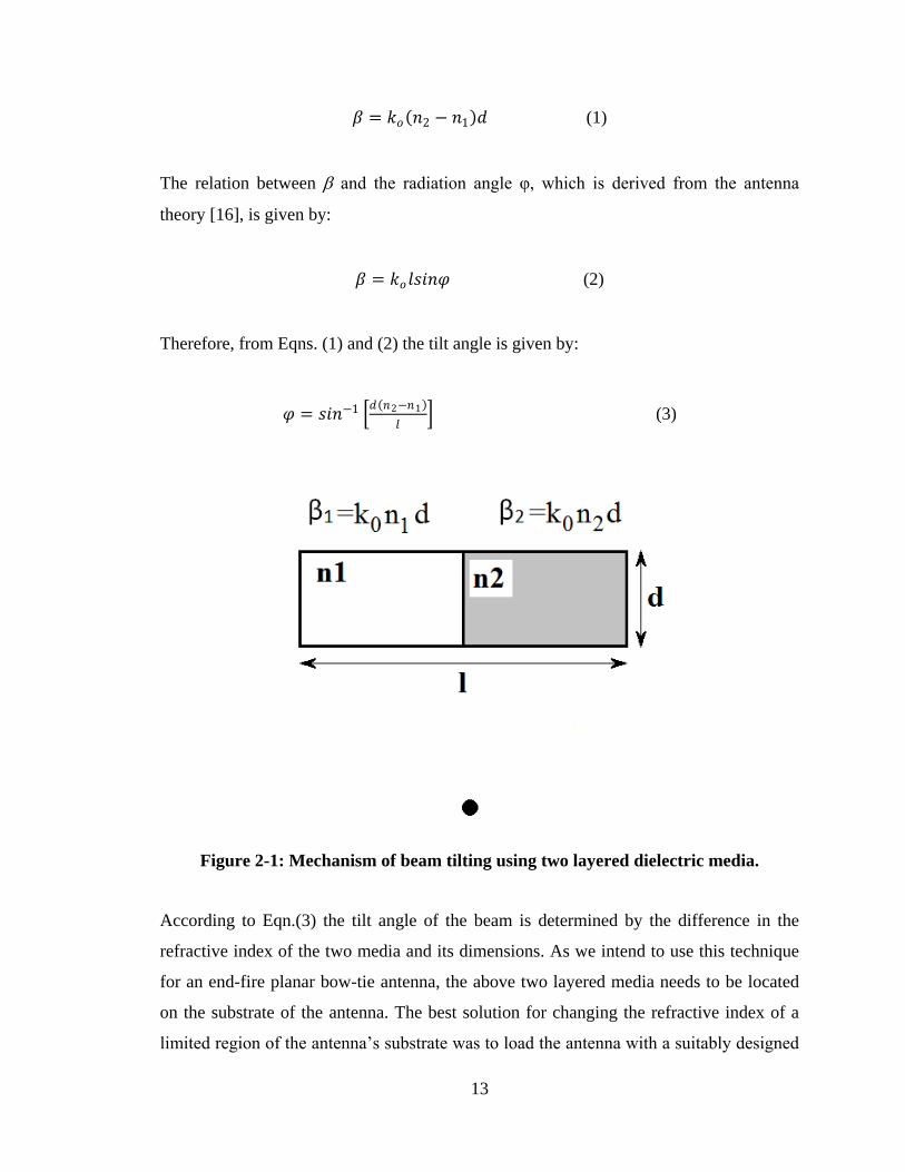
Figure 2-1: Mechanism of beam tilting using two layered dielectric media. .................... 13
Figure 2-2: Geometry of the proposed unit-cell implemented on a dielectric substrate. ... 14
Figure 2-3: Measurement setup for acquiring the S-parameters of the unit-cell array. ..... 15
Figure 2-4: The S-parameters of proposed unit-cell structure. .......................................... 16
Figure 2-5: Retrieved parameters (n, ε, and μ) of meandered-line H-shape unit-cell........ 17
Figure 2-6: The extracted permittivity and permeability of the H-shaped and proposed
meandered-line unit-cell. ................................................................................................... 18
Figure 2-7: Configuration of proposed antenna embedded with IML unit-cells on the top
surface of substrate. ........................................................................................................... 18
Figure 2-8: Radiation patterns of proposed antenna in the E-plane (xy) with IML unit-
cells and a conventional bow-tie antenna at 7.5 GHz. ....................................................... 19
Figure 2-9: Radiation Poynting vector and E-field distribution over the antenna at 7.5
GHz (a) & (c) with IML, and (b) & (d) without IML. ....................................................... 20
Figure 2-10: Radiation pattern of proposed antenna with different columns of unit-cell
loading in the y-direction. .................................................................................................. 21

xi
Figure 2-11: The radiation pattern of antenna in the E-plane as a function of .................. 22
Parameter h ........................................................................................................................ 22
Figure 2-12: Photograph IML antenna, (a) top view, (b) bottom view. ............................ 23
Figure 2-13: Reflection-coefficient of bow-tie antenna loaded with IML......................... 24
Figure 2-14: Radiation pattern of proposed antenna with IML at: (a) 7.3 GHz, (b) 7.5
GHz, (c) 7.7 GHz, and (d) with IML in the H-plane at 7.5 GHz. ...................................... 26
Figure 3-1: Mechanism of beam-tilting in the E-plane of the bow-tie antenna. ................ 29
Figure 3-2: Configuration of proposed split-ring resonator (SRR) on the top and bottom
surface of RO 5880 substrate. ............................................................................................ 30
Figure 3-3: The S-parameter response of the proposed SRR unit-cell. ............................. 31
Figure 3-4: The extracted effective permittivity, permeability and refractive index of the
split ring resonator. ............................................................................................................ 31
Figure 3-5: Configuration of proposed antenna embedded with SRR unit-cells, (a) on the
bottom, and (b) on the top surface of substrate. ................................................................. 32
Figure 3-6: Radiation patterns of proposed antenna in the E-plane (xy) with SRR unit-
cells and a conventional bow-tie antenna at 5.4, 6.2, and 7.2 GHz. .................................. 33
Figure 3-7: Poynting vector distribution over the antenna at 6.2 GHz, (a) without SRR,
and (b) with SRR. .............................................................................................................. 33
Figure 3-8 Photograph of SRR bow-tie antenna, (a) bottom view, and (b) Top surface of
substrate. ............................................................................................................................ 34
Figure 3-9 The simulation and measured reflection-coefficient of the SRR rounded bow-
tie antenna. ......................................................................................................................... 35
Figure 3-10: The normalized radiation patterns of the rounded bow-tie antenna with 8×6
SRR in the E-plane (xy) at: (a) 5.4 GHz, and (b) 7.2 GHz ................................................ 35
Figure 4-1: Base-station dipole antenna array which can be substituted with the proposed
double G-shaped bow-tie antenna. ..................................................................................... 37
xii
Figure 4-2: (a) Geometry of the planar Bow-tie antenna, and (b) its normalized radiation
pattern in the H-plane. ........................................................................................................ 40
Figure 4-3: Mechanism of beam tilting in the H-plane of Bow-tie antenna. ..................... 41
Figure 4-4: The proposed double G-shaped resonator (DGR) unit-cell fabricated on a
dielectric substrate. ............................................................................................................ 42
Figure 4-5: Refractive-index of proposed DGR unit-cell as a function of frequency. ...... 43
Figure 4-6: Extracted permittivity and permeability of the CCR and DGR unit-cell. ....... 44
Figure 4-7: Radiation pattern of the antenna with 1×2 and 1×4 DGR unit-cells placed on
the substrate. ...................................................................................................................... 45
Figure 4-8: 3D configuration of proposed antenna with 5×4 array of DGR antenna. ...... 45
Figure 4-9: Radiation pattern of the antenna in the H-plane with and without DGR
loading. ............................................................................................................................... 46
Figure 4-10: Poynting vector distribution over the antenna in the H-plane (yz) at 3.5 GHz,
(a) without DGR loading, and (b) with DGR loading. ...................................................... 47
Figure 4-11: Normalized H-plane radiation pattern of the antenna loaded with the DGR
array and implemented on a substrate having εr = 2.2; and when the DGR array is
replaced with a plain dielectric substrate of εr = 9.1 .......................................................... 47
Figure 4-12: Bow-tie antenna with 5-layer lens where each layer comprises of one DGR
unit-cell. ............................................................................................................................. 48
Figure 4-13: Radiation pattern of proposed antenna with different number of unit-cell
loading in the z-direction ................................................................................................... 49
Figure 4-14: (a) Dual-polarized 5×3 DGR antenna array, and (b) H-plane radiation pattern
of dual-polarized antenna at 3.5 GHz. ............................................................................... 50
Figure 4-15: Radiation pattern of antenna when integrated with 5×4 CCR arrays. .......... 51
Figure 4-16: Photograph of the fabricated antenna loaded with 5×4 DGR unit-cells. ...... 52
Figure 4-17: Measured reflection-coefficient of the Bow-tie antenna with and without
DGR array loading. ............................................................................................................ 53
xiii
Figure 4-18: Measured radiation pattern of the proposed antenna in the H-plane with and
without DGR loading at: 3.4 GHz, 3.5 GHz, and 3.6 GHz .............................................. 53
Figure 4-19: Measured radiation pattern of the proposed antenna in the E-plane with and
without DGR unit-cells at 3.5 GHz. ................................................................................... 54
Figure 4-20: (a) DGR antenna array arrangement to deflect the beam from -32 to 32o
respect to the end-fire direction (+y), (b) measured radiation pattern of the dual-feed
Bow-tie antenna with DGR loading in the H-plane. .......................................................... 56
Figure 4-21: Insertion and reflection-coefficient of the DGR antenna array arrangement
in Fig. 4-19. ........................................................................................................................ 56
Figure 5-1: Configuration of the proposed tilted bow-tie antenna with DGR and an array
of ZIM unit-cells ................................................................................................................ 59
Figure 5-2: The normalized radiation patterns of the un-tilted bow-tie antenna in the E-
and H-planes at 60 GHz. Angle is in degrees and radius in dB. ........................................ 61
Figure 5-3: Antenna gain response as a function of bow-tie tilt angle. ............................. 61
Figure 5-4: The normalized radiation patterns of the tilted bow-tie antenna in the E- and
H-planes at 60 GHz. Angle is in degrees and radius in dB. ............................................... 62
Figure 5-5: The structure of the double G-shaped resonator. ............................................ 63
Figure 5-6: S-parameter (|S12| and |S11|) response of the DGR configuration. ................ 64
Figure 5-7: The normalized radiation patterns of the proposed antenna with and without
DGR loading in the E-and H-planes. Angle is in degrees and radius in dB. ..................... 65
Figure 5-8: The E-field distribution over the tilted antenna: (a) with DGR loading, and (b)
without DGR loading. ........................................................................................................ 65
Figure 5-9: Comparison of bow-tie antenna gain for un-tilted and tilted radiators, and the
antenna gain for a tilted bow-tie antenna with DGR loading. ........................................... 66
Figure 5-10:The configuration of the ZIM unit-cell. ......................................................... 67
Figure 5-11:S-parameter (|S12| and |S11|) response of the proposed ZIM bow-tie antenna.
............................................................................................................................................ 67
xiv
Figure 5-12: Retrieved characterizing parameters of the ZIM unit-cell, i.e. permittivity,
permeability, and refractive index. .................................................................................... 68
Figure 5-13: Antenna gain with various ZIM unit-cell arrangements. .............................. 69
Figure 5-14: The normalized radiation patterns of the final antenna in the E- and H-planes
at 60 GHz. Angle is in degrees and radius in dB. .............................................................. 69
Figure 5-15: The E-field distribution over the antenna at 60 GHz. ................................... 70
Figure 5-16: Photograph of the fabricated prototype antenna, (a) top, and (b) bottom. .... 71
Figure 5-17: Measured and simulated reflection coefficient of the ZIM tilted bow-tie
antenna. .............................................................................................................................. 71
Figure 5-18: Photograph of the antenna measurement set-up............................................ 72
Figure 5-19: Normalized simulated and measured radiation patterns of the proposed
antenna in the E-plane(x-y) at: (a) 58 GHz, (b) 60 GHz (c), 62 GHz, and (d) 64 GHz.
Angle is in degrees and radius in dB. ................................................................................ 72
Figure 5-20: Normalized simulated and measured radiation patterns of the proposed
antenna in the H-plane (yz) at: (a) 58 GHz, (b) 60 GHz, (c) 62 GHz (d), and 64GHz.
Angle is in degrees and radius in dB. ................................................................................ 73
Figure 5-21: Measured insertion-loss of back-to-back end-launch connectors along with
SIW microstrip line. ........................................................................................................... 74
Figure 6-1: Ray paths from the offset axis of dipole antenna with 5×4 array of GRIM. .. 78
Figure 6-2: Radiation patterns of the dipole antenna with dielectric slab constituted from
5×4 array of GRIM unit-cells, and dielectric slab with identical loading. ........................ 79
Figure 6-3: Geometry of the proposed GRIM unit-cell implemented on a dielectric
substrate. ............................................................................................................................ 80
Figure 6-4: Magnitude of S12 of the proposed GRIM unit-cell structure . ....................... 81
Figure 6-5: Relative permittivity, permeability and refractive-index of Type A and B
elements. ............................................................................................................................ 82
Figure 6-6: Relative permittivity, permeability and refractive-index of Type C and D
elements. ............................................................................................................................ 83
xv
Figure 6-7: Phase of the proposed GRIM unit-cell structure . ........................................... 83
Figure 6-8: Configuration of proposed antenna embedded with GRIM unit-cell on the top
and bottom surface of the substrate.................................................................................... 84
Figure 6-9: Radiation patterns of proposed antenna in the E-plane (xy) with GRIM unit-
cells and a conventional dipole antenna at 60 GHz ........................................................... 85
Figure 6-10: Poynting vector distribution over the antenna at 60 GHz: (a) with GRIM,
and (b) without GRIM ....................................................................................................... 86
Figure 6-11: Radiation pattern of antenna as a function of number of GRIM unit-cell
columns .............................................................................................................................. 87
Figure 6-12: Radiation pattern for a 5×4 GRIM as a function of feed-line offset along the
x-direction at 61 GHz unit-cell columns ............................................................................ 87
Figure 6-13: Radiation pattern of antenna having dielectric slab loaded with GRIM unit-
cells and slab with identical unit-cells. .............................................................................. 88
Figure 6-14: (a) Photograph of dipole antenna with GRIM array, and (b) simulated and
measured reflection coefficient .......................................................................................... 89
Figure 6-15: The normalized radiation pattern of single dipole-antenna with a 5×4 array
of GRIM loading at 60 GHz in the (a) E-plane (xy), and (b) H-plane (yz). ...................... 89
Figure 6-16: Geometry of double-feed antenna with 5×4 array of GRIM unit-cells ......... 90
Figure 6-17: The measured reflection coefficient of the double dipole GRIM antenna with
inset photograph of fabricated antenna. ............................................................................. 91
Figure 6-18: The simulated normalized radiation pattern when beam is switched in three
states +26o, 0
o, and -26
o at 61 GHz .................................................................................... 92
Figure 6-19: Normalized radiation pattern of proposed antenna with GRIM loading in the
E-plane when port 1 is excited at: (a) 58 GHz, (b) 61 GHz, (c) 63 GHz, and (d) with
GRIM loading in the H-plane at 60 GHz ........................................................................... 92
Figure 6-20: Normalized radiation pattern of proposed antenna with GRIM loading in E-
plane when port 2 is excited at: (a) 59 GHz, and (b) 63 GHz. ........................................... 93
Figure 6-21: Configuration of fourth-feed antenna with 5×4 GRIM unit-cells. ................ 94
xvi
Figure 6-22: Radiation pattern of proposed four-feed antenna with GRIM array in E-plane
to realize five angle beams switching at 61 GHz. .............................................................. 95
Figure 6-23: Radiation pattern at 60 GHz of the quad-feed antenna when (a) port 1 is
excited, and (b) port 2 is excited. ....................................................................................... 95
Figure 7-1: Mechanism of beam-tilting in the H-plane of the dipole antenna. .................. 99
Figure 7-2: Geometry of the proposed HRIM unit-cell implemented on a dielectric
substrate. .......................................................................................................................... 100
Figure 7-3: Insertion loss response Geometry of the proposed HRIM unit-cell structure.
.......................................................................................................................................... 101
Figure 7-4: Real part of effective refractive index of the HRIM unit-cell ....................... 102
Figure 7-5: Configuration of the antenna embedded with a 3×4 array of the proposed
HRIM unit-cells on upper surface of antenna substrate ................................................... 103
Figure 7-6: Radiation patterns of proposed antenna in the H-plane(yz) with proposed unit-
cell and a conventional dipole antenna with no loading HRIM at 60 GHz. .................... 104
Figure 7-7:Radiation pattern of antenna in terms of different unit-cells loaded in the y-z
direction ........................................................................................................................... 105
Figure 7-8: Configuration of two-dipole antenna when integrated with HRIM unit-cells.
.......................................................................................................................................... 106
Figure 7-9: The normalized radiation pattern of elevation plane(H-plane) when working
in two states at 60 GHz .................................................................................................... 106
Figure 7-10: Configuration of two dipole antenna when integrated with HRIM in the
azimuth and elevation planes . ......................................................................................... 107
Figure 7-11: Radiation pattern of the antenna in E and H-plane when is loaded with
metamaterial unit-cells in the azimuth and elevation plane at 60 GHz ........................... 108
Figure 7-12: Photograph of the single-feed antenna with HRIM loading in elevation
plane. ................................................................................................................................ 109
Figure 7-13: The measured reflection-coefficient of the single dipole antenna with HRIM
unit-cell loading. .............................................................................................................. 110
xvii
Figure 7-14:The normalized radiation patterns of the single dipole-antenna with 3×4
HRIM in the H-plane (yz) at: (a) 58 GHz, (b) 60 GHz, and (c) 62 GHz. ........................ 110
Figure 7-15: The normalized radiation pattern of the single dipole antenna with 3×4 array
of HRIM unit-cells in the E-plane (xy) at 60 GHz. ......................................................... 111
Figure 7-16: The measured and simulated antenna gain. ................................................. 112
Figure 8-1: The dipole antenna loaded by MNZ unit-cells in the azimuth plane. ........... 116
Figure 8-2: Geometry of the proposed MNZ unit-cell implemented on a dielectric
substrate. .......................................................................................................................... 117
Figure 8-3: Magnitude of S12 of the proposed MNZ unit-cell structure as a function of
the parallel coupled gap size. ........................................................................................... 118
Figure 8-4: Real-part of effective permeability of the MNZ unit-cell. ............................ 119
Figure 8-5: The magnitude of transmission coefficient with vertical and horizontal
polarizations. .................................................................................................................... 120
Figure 8-6: Configuration of proposed antenna integrated with 10 slabs of MNZ unit-
cells. ................................................................................................................................. 121
Figure 8-7: Co- and cross-polarization of the proposed antenna in the E-plane (xy) loaded
with MNZ unit-cells, and a conventional dipole antenna at 60 GHz ............................... 121
Figure 8-8: Radiation patterns of proposed antenna in the E-plane (xy) in terms of the
number of MNZ slabs along the x-direction at 60 GHz .................................................. 122
Figure 8-9: The peak realized gain of antenna as a function of different MNZ layers. ... 123
Figure 8-10: The Radiation patterns of proposed antenna in the E-plane (xy) as a function
of the dipole antenna position along the x-direction at 60 GHz. ..................................... 124
Figure 8-11: Radiation patterns of proposed antenna in the E-plane (xy) in terms of
decreasing the number of unit-cells at two last layers at 60 GHz .................................... 124
Figure 8-12: Surface current distribution on the MNZ unit-cells at 60 GHz. .................. 125
Figure 8-13: Poynting vector points in the E-plane (xy) at 60 GHz. ............................... 125
Figure 8-14: Configuration of two-dipole antenna when integrated with MNZ.............. 126
xviii
unit-cells. .......................................................................................................................... 126
Figure 8-15: The radiation pattern in the azimuth plane at 60 GHz. ............................... 127
Figure 8-16: 3D configuration of the two-dipole antenna when integrated with MNZ unit-
cells in both E-and H-planes. ........................................................................................... 128
Figure 8-17:2D normalized E- and H-plane radiation patterns of the two dipole antenna
when integrated with MNZ unit-cells in the azimuth and elevation planes. .................... 128
Figure 8-18: Radiation patterns of proposed antenna in the H-plane (yz) with different
layers at 60 GHz. .............................................................................................................. 129
Figure 8-19: 3D radiation pattern of two-dipole antenna when integrated with MNZ unit-
cells in both E-and H-planes when: (a) port 1 is excited and port 2 terminated, and (b)
port 2 is excited and port 1 terminated. ............................................................................ 129
Figure 8-20: Configuration of two-dipole antenna when integrated with MNZ mamaterial
unit-cells in the azimuth and elevation planes ................................................................. 130
Figure 8-21: 3D radiation pattern of two-dipole antenna when integrated with MNZ unit-
cells in both E-and H-planes when: (a) port 3 is excited, and (b) port 4 is excited. ........ 131
Figure 8-22: Photograph of the double feed antenna with MNZ loaded in the azimuth
plane. ................................................................................................................................ 132
Figure 8-23: The measured reflection-coefficient of MNZ dipole antenna. .................... 133
Figure 8-24: The normalized simulation and measured radiation patterns of double dipole
antenna with 10 slabs of MNZ unit-cells in the E-plane (yz) at (a) 58 GHz, (b) 60 GHz,
(c) 62 GHz, and (d) 64 GHz ............................................................................................. 133
Figure 8-25: Photograph of the 2D beam-scanning MIMO antenna loaded by MNZ unit-
cells in azimuth and elevation planes. .............................................................................. 134
Figure 8-26: The normalized simulation and measured radiation patterns of two-
dimensional dipole antenna with 8 slabs of MNZ unit-cells at 60 GHz when port 1 is
excited in (a) H-plane (yz), and (b) E-plane (xy). ............................................................ 135
Figure 8-27: The normalized simulation and measured radiation patterns in E-plane (xy)
when port 3 is excited at 60 GHz. .................................................................................... 136

xix
Figure 9-1: Geometry of the proposed H-shaped metamaterial unit-cell fabricated on the
dielectric 5880 substrate. ................................................................................................. 140
Figure 9-2: The extracted characterizing parameters of proposed unit-cell including
permittivity, permeability and refractive index................................................................ 141
Figure 9-3: The structure of the H-shaped unit-cell. ........................................................ 142
Figure 9-4: S-parameter (S12 and S11) response of the H-shaped configuration. .......... 142
Figure 9-5: Configuration of the antenna embedded with a 3x4 array of the proposed
HRIM unit-cells on upper surface of antenna substrate. .................................................. 143
Figure 9-6: The radiation pattern of antenna in the E-plane with different arrangement of
tilted and un-tilted unit-cells at 60 GHz. .......................................................................... 144
Figure 9-7: Configuration of the bow-tie antenna embedded with high dielectric constant
material instead of stub-loaded H-shaped unit-cells. ....................................................... 145
Figure 9-8: The radiation patterns of the antenna in the E-plane when loaded with higher
dielectric constant substrate. ............................................................................................ 146
Figure 9-9: The normalized radiation patterns of the dual-beam bow-tie antenna in the E-
plane (xy) at 58, 60, and 62 GHz. .................................................................................... 147
Figure 9-10: The poynting distribution normalized of dual beam antenna at 60 GHz. ... 148
Figure 9-11: Photograph of the dual-beam bow-tie antenna loaded with stub-loaded H-
shaped unit-cells. .............................................................................................................. 148
Figure 9-12: The measured reflection-coefficient of the dual-beam bow-tie antenna. .... 149
Figure 9-13: The normalized radiation patterns of the dual-beam bow-tie antenna using an
array of stub-loaded H-shaped unit-cells in the E-plane (xy) at: (a) 58 GHz, (b) 60 GHz,
and (c) 63 GHz. ................................................................................................................ 150
Figure 11-1: Le mécanisme d‟inclinaison du faisceau en utilisant des milieux électriques a
deux couches. ................................................................................................................... 159
Figure 11-2: La géométrie de la cellule unitaire située sur un substrat diélectrique ....... 160
Figure 11-3: La configuration de l‟antenne proposée utilisant des cellules en
métamatériau sur la surface supérieure de substrat .......................................................... 161
xx
Figure 11-4 : Les diagrammes du rayonnement de l‟antenne proposée dans le plan
électrique (xy) avec les cellules unitairesen métamatériau intégré avec une antenne nœud
papillon à 7,5 GHz. .......................................................................................................... 162
Figure 11-5: Le diagramme du rayonnement de l‟antenne aux cellules unitaire DGR 1×2
et 1×4 située sur le substrat .............................................................................................. 163
Figure 11-6: La configuration 3D de l‟antenne proposée avec le réseau 5×4 de l‟antenne
DGR. ................................................................................................................................ 164
Figure 11-7 : Le diagramme du rayonnement de l‟antenne dans plan magnétique avec ou
sans le chargement DGR. ................................................................................................. 164
Figure 11-8 : La configuration de l‟antenne inclinée en forme du nœud papillon avec
DGR et un réseau des cellules unitaires en métamatériau un indice zéro ........................ 166
Figure 11-9 : Les diagrammes normalisés du rayonnement de l‟antenne non- inclinée en
forme du nœud papillon dans les plans magnétique et électrique à 60 GHz. L‟angle est
exprimé en degrés et le rayon est exprimé en dB. ........................................................... 167
Figure 11-10 : Les diagrammes du rayonnement normalisés, simulées et mesurées pour
l‟antenne proposée dans le plan électrique (x-y) quand c‟est intégrée par les résonateurs
DGR et les cellules unitaires en métamatériau à indice zéro a : (a) 58 GHz, (b) 60 GHz,
(c) 62 GHz, et (d) 64 GHz. L‟angle est exprimé en degrés et le rayon est exprimé en dB.
.......................................................................................................................................... 167
Figure 11-11 : Les diagrammes du rayonnement normalisés, simulées et mesurées pour
l‟antenne proposée dans le plan magnétique (yz) quand c‟est intégrée par les résonateurs
DGR et les cellules unitaires en métamatériau à indice zéro a : (a) 58 GHz, (b) 60 GHz,
(c) 62 GHz, et (d) 64 GHz. L‟angle est exprimé en degrés et le rayon est exprimé en dB.
.......................................................................................................................................... 168
Figure 11-12: La configuration de l‟antenne proposée avec un milieu à gradient d‟indice
de réfraction place sur les surfaces supérieure et inferieure du substrat. ......................... 170
Figure 11-13 : Les diagrammes du rayonnement de l‟antenne proposée dans le plan
électrique (xy) équipée avec un milieu à gradient à indice de réfraction et une antenne
dipôle classique à 60 GHz. ............................................................................................... 171
xxi
Figure 11-14: La configuration de l‟antenne charge avec un réseau des cellules unitaires
HRIM aux surfaces supérieure et inferieure du substrat. ................................................. 172
Figure 11-15: Les diagrammes du rayonnement de l‟antenne proposée dans le plan
magnétique (yz) avec et sans chargement HRIM à 60 GHz. ........................................... 173
Figure 11-16: La configuration de l‟antenne proposée avec 10 plaques des cellules
unitaires MNZ. ................................................................................................................. 175
Figure 11-17: La polarisation croisée et copolarisation de l‟antenne proposée dans le plan
électrique (xy) avec et sans à 60 GHz. ............................................................................. 176
Figure 11-18 : La configuration 3D de l‟antenne dipôle-double avec MNZ dans les plans
électrique et magnétique .................................................................................................. 177
Figure 11-19 : Le diagramme du rayonnement bidimensionnel normalise dans les plans
électrique et magnétique pour l‟antenne dipôle et sans MNZ . ...................................... 177
Figure 11-20 : La configuration de l‟antenne intégrante un réseau 3×4 des cellules
unitaires HRIM au surface supérieur du substrat de l‟antenne ........................................ 178
Figure 11-21: Le diagramme du rayonnement de l‟antenne dans le plan électrique à un
arrangement différent des cellules unitaires inclinés et non-inclinés à 60 GHz. ............. 179
ABSTRACT
The ISM frequency band at 60 GHz (57-64 GHz) has attracted much attention for its
large frequency bandwidth (7 GHz). This band enables multi Gb/s data rate transmission
and enhanced immunity as well as frequency re-use. However, due to the atmospheric
absorption loss at this band the propagated signal degrades considerably. This issue can
xxii
be compensated by using high-gain antennas. Beam alignment is another challenge for
high gain antennas where the location of transmitter or receiver is not fixed. This is due to
narrow beamwidth of such antennas. The solution to resolve this issue is using beam
switching or beam scanning networks such as phased antenna arrays. Existing
beamforming systems based on phased antenna array incur large loss and are complex to
implement in practice rendering them high-cost solution. An alternate solution proposed
in this thesis is to realize beam tilting using metamaterials to minimize the loss and cost
issues as well as obtain a low-profile structure.
In this dissertation, first and foremost, an array of meander line H-shaped
resonators, which operate as an anisotropic metasurface at C-band, were integrated in
front of a standard bow-tie antenna in order to tilt the direction of the antenna‟s main
beam in the azimuth plane. In order to tilt the antenna‟s radiation beam in the elevation
plane an array of inhomogeneous split-ring resonators are embedded in the H-plane of
end-fire bow-tie antenna. The proposed designs are shown to provide a viable solution for
next generation of base-station antennas that need to be capable of tilting the direction of
the main beam under the horizon. This particularly includes 5G wireless cellular networks
envisaged to operate at millimeter-waves. The proposed technique is also applicable at C-
band (7-8 GHz) and WiMAX band (3.4-3.6 GHz).
The high-gain antenna proposed here for operation at millimeter-wave (57-64
GHz) is based on a bow-tie configuration which is fed by surface integrated waveguide
(SIW). The technique proposed here to increase the antenna gain involves (i) embedding
a split-ring resonator at the back side of bow-tie antenna, (ii) tilting the bow-tie radiators
with respect to the end-fire direction, and (iii) integrating an array of folded H-shaped
resonators to create a region of low refractive index in front of the bow-tie radiator in
order to convert the antenna‟s spherical waves into planar waves. The measured results
indicate that the antenna gain improves to 12 dBi over 57-64 GHz.
Another technique demonstrated here to deflect the main beam of a standard
dipole antenna involves incorporating in the azimuth plane of the antenna a media with
gradient index of refraction. This technique enables beam switching from -58 to +58
degrees over 57-64 GHz with maximum gain of 9.5 dBi at 60 GHz.
xxiii
In order to obtain beam steering in the Elevation plane, the proposed folded H-
shaped resonators are loaded in the E and H-plane of dipole. This arrangement is shown
to provide two-dimensional beam tilting or beam switching at 60 GHz. However with this
approach, the antenna gain is limited to 10 dBi and the beam deflection is limited to 17
degrees in both planes.
To achieve a higher gain and tilt angle an array of split-ring resonators (SRR)
were integrated in front of a quasi TE-source generated by a dipole antenna at 60 GHz.
The magnetic resonance of the SRRs result in a tilt angle of 34 degrees in both the
azimuth and elevation planes with maximum peak realized gain of 14 dBi over 57-64
GHz.
Finally, to achieve a dual beam and broad beamwidth radiation in the azimuth
plane of end-fire bow-tie antenna an array of stub-loaded H-shape resonators were
integrated in front of the antenna. The measured results show beam deflection at +30 and
-30 degrees with respect to the end-fire direction with the maximum peak realized gain of
9 dBi at 60 GHz.

xxiv
ACKNOWLEDGMENTS
First of all, I sincerely wish to thank my supervisor Prof. Tayeb A.Denidni, who gave me
the opportunity to join his group, and let me work on different projects. It was a real
pleasure to for me to have such an exceptional scholar and it was my honor to be his PhD
student.
Furthermore, I would like to thank my committee members, Prof.Tatu, Prof.Kishk,and
Prof.Laurin for their review of my dissertation and their numerous constructive comments
and feedback.
Finally, I want to thank my wife Naeemeh for her love and support, during this period of
time.
1
Chapter 1 INTRODUCTION
1.1 Background and Motivation
With rapid development in wireless communication systems such as mobile
communications, which is omnipresent everywhere in our daily life, a huge amount of
information is accessible with high speed near the speed of light. Antenna is the key
component of wireless technology which is utilized for different applications enabling
high data rate transmission, point-to-point and mobile cellular communications.
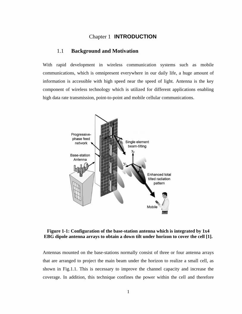
Figure 1-1: Configuration of the base-station antenna which is integrated by 1x4
EBG dipole antenna arrays to obtain a down tilt under horizon to cover the cell [1].
Antennas mounted on the base-stations normally consist of three or four antenna arrays
that are arranged to project the main beam under the horizon to realize a small cell, as
shown in Fig.1.1. This is necessary to improve the channel capacity and increase the
coverage. In addition, this technique confines the power within the cell and therefore
2
minimizes adjacent channel interference. The radiation from the antenna can be tilted
either by mechanical or electronic means. Mechanical tilting involves physically
changing the position of the antenna element whereas electronic tilting can be achieved
by using phased antenna arrays. One approach used to tilt the direction of the main beam
electronically involves integrating a phase shifter, which can be designed using RF
MEMS and PIN diodes, into the antenna element and change progressively the phase of
each element so as to steer the main beam radiation into the pre-defined direction.
Although, with this approach the radiation beam can be tilted at the desired angle, the
gain of the antenna is severely degraded since the 3 dB beamwidth of the single radiating
element is not broad enough to follow the overall radiation beam emanating from the
array. The other drawback of electronic beam steering is the limited scan angle. Although
the mechanical beam tilting option provides a fixed angle beam with no degradation in
the antenna gain, however installation and implementation of the mechanical approach
over the electronic approach in base-stations is very costly. To deal with this issue, an
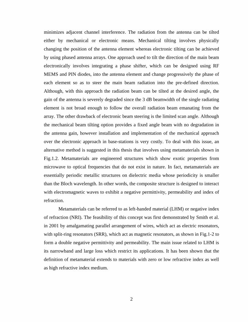
alternative method is suggested in this thesis that involves using metamaterials shown in
Fig.1.2. Metamaterials are engineered structures which show exotic properties from
microwave to optical frequencies that do not exist in nature. In fact, metamaterials are
essentially periodic metallic structures on dielectric media whose periodicity is smaller
than the Bloch wavelength. In other words, the composite structure is designed to interact
with electromagnetic waves to exhibit a negative permittivity, permeability and index of
refraction.
Metamaterials can be referred to as left-handed material (LHM) or negative index
of refraction (NRI). The feasibility of this concept was first demonstrated by Smith et al.
in 2001 by amalgamating parallel arrangement of wires, which act as electric resonators,
with split-ring resonators (SRR), which act as magnetic resonators, as shown in Fig.1-2 to
form a double negative permittivity and permeability. The main issue related to LHM is
its narrowband and large loss which restrict its applications. It has been shown that the
definition of metamaterial extends to materials with zero or low refractive index as well
as high refractive index medium.
3
Figure 1-2: Homogenous metamaterial unit-cell comprised of DSR and wire as a
double negative metamaterial region [2]
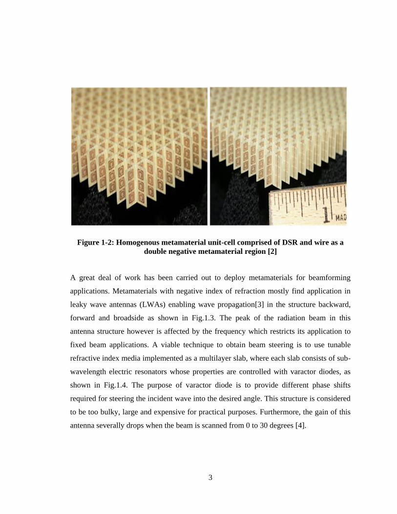
A great deal of work has been carried out to deploy metamaterials for beamforming
applications. Metamaterials with negative index of refraction mostly find application in
leaky wave antennas (LWAs) enabling wave propagation[3] in the structure backward,
forward and broadside as shown in Fig.1.3. The peak of the radiation beam in this
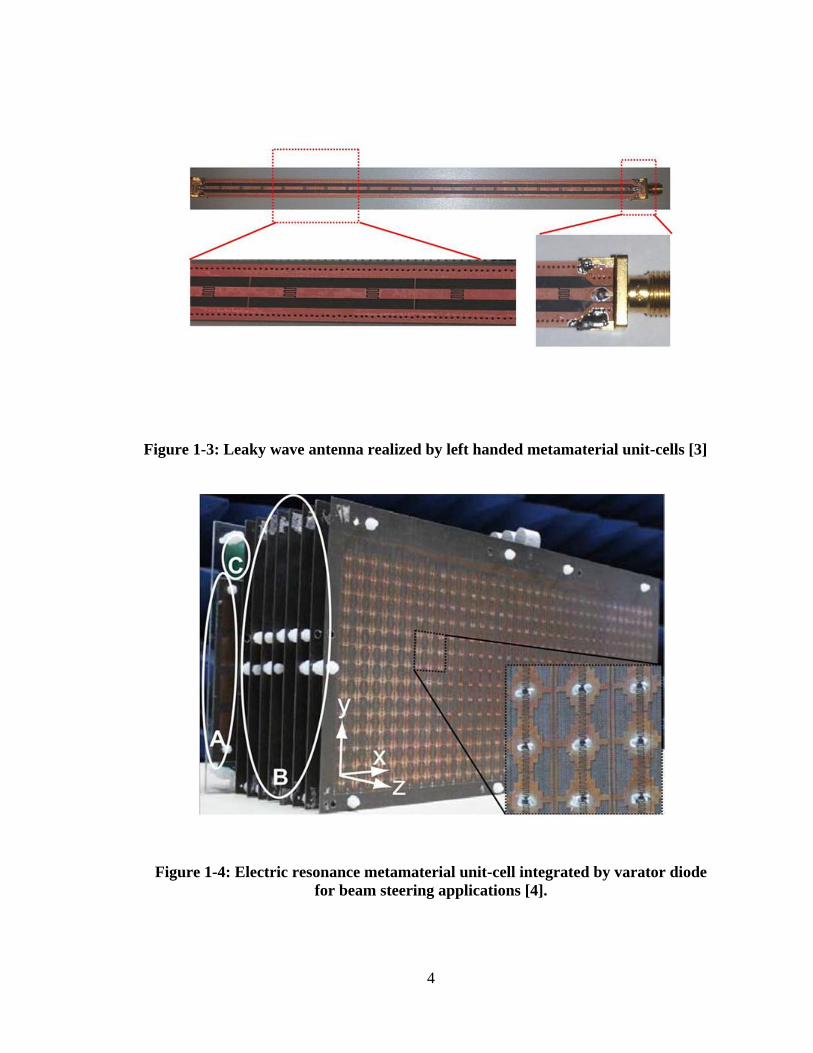
antenna structure however is affected by the frequency which restricts its application to
fixed beam applications. A viable technique to obtain beam steering is to use tunable
refractive index media implemented as a multilayer slab, where each slab consists of sub-
wavelength electric resonators whose properties are controlled with varactor diodes, as
shown in Fig.1.4. The purpose of varactor diode is to provide different phase shifts
required for steering the incident wave into the desired angle. This structure is considered
to be too bulky, large and expensive for practical purposes. Furthermore, the gain of this
antenna severally drops when the beam is scanned from 0 to 30 degrees [4].
4
Figure 1-3: Leaky wave antenna realized by left handed metamaterial unit-cells [3]
Figure 1-4: Electric resonance metamaterial unit-cell integrated by varator diode
for beam steering applications [4].
5
The millimeter-wave frequency bandwidth is recognized to extend from 30-300
GHz with a corresponding wavelength of 10-1 mm wavelength. Recently, work at 60
GHz frequency band has attracted considerable attention for its large bandwidth from 57-
64 GHz, which can enable wireless data transmission in excess of 1.5 gigabit per second
for high definition video transfer, and high resolution imaging application. However, at
this frequency the electromagnetic wave is absorbed greatly by oxygen molecules and
hence the path loss is high (10–16 dB/km). To overcome this issue requires the use of a
high-gain antenna which has the added benefit of minimizing channel distortion caused
by multipath effects. Therefore directive antenna is a good candidate for the line-of-sight
applications at 60 GHz. As the position of the receiver is not known precisely beam
alignment between transmitter and receiver is another challenging requirement.
Figure 1-5: Dielectric lens antenna integrated by horn antenna for mechanically
beam tilting at 60 GHz [5].
6
To deal with the latter issue, a steerable antenna is proposed here. A great deal of work
has been carried out in this research to steer the direction of the radiation beam from an
antenna at millimeter-wave. It is well known that phased antenna array or adaptive
antenna array is a suitable technique for steering the beam, which enables sufficiently
high signal-to-noise ratio to be established at the receiver. The deployment of phase
antenna array requires the integration of many phase shifters, which introduces large loss
in the system and is an expensive solution. Reconfigurable reflect array is another
technique to scan the beam in both azimuth and elevation planes. This technique requires
the integration of a large number of active elements such as PIN diodes in the antenna,
which also makes it an expensive solution. Dielectric lens antenna, shown in Fig.1.5, is
another technique for beam steering demonstrated at millimeter-wave frequencies [5].
These kinds of beam steering structures are bulky and appropriate for radar imaging
systems.
1.2 Dissertation Outline
The dissertation is divided into 9 chapters with the abstract, publication list, and the
reference. The contents of the dissertation charters are listed below. The main objective
of the research was to develop a low-profile, low cost antenna which has the functionality
to tilt the direction of the main beam in the azimuth and elevation planes without severely
affecting its performance. For this purpose, an end-fire type of antenna was selected, in
particular a classical dipole antenna which was a bow-tie antenna. The direction of
radiation beam from the bow-tie antenna was steered in the E- and H-planes by
integrating metamaterial or metasurface media, which were created with microstrip unit-
cells.
Chapter 2 presents a technique to re-direct the radiation beam from a planar
antenna in a specific direction with the inclusion of metamaterial loading. The
beam-tilting approach described here uses the phenomenon based on phase
change resulting from an EM wave entering a medium of different refractive
7
index. The metamaterial H-shaped unit-cell structure is configured to provide a
high refractive index which was used to implement beam tilting in a bow-tie
antenna. The fabricated unit-cell was first characterized by measuring its S-
parameters. Hence, a two dimensional array was constructed using the proposed
unit-cell to create a region of high refractive index which was implemented in the
vicinity bow-tie structure to realize beam-tilting. The simulation and experimental
results show that the main beam of the antenna in the E-plane is tilted by 17
degrees with respect to the end-fire direction at 7.3, 7.5, and 7.7 GHz. Results also
show unlike the conventional beam-tilting antennas, no gain drop is observed
when the beam is tilted; in fact ,there is a gain enhancement of 2.73 dB compared
to the original bow-tie antenna at 7.5 GHz. The reflection-coefficient of the
antenna remains < -10 dB in the frequency range of operation.
Chapter 3 presents a meta-surface implemented with magnetic resonance created
with split-ring resonator unit-cells are used to realize wideband beam-tilting in an
end-fire antenna. The end-fire antenna has rounded bow-tie configuration for
wideband operation over 3.5–8 GHz. The antenna is integrated with 8×6 array of
magnetic resonance unit-cells that are located off-axis in front of the bow-tie
antenna in the azimuth plane. The interaction of the radiation beam with the meta-
surface causes the direction of the radiation beam to be tilted in the E-plane.
Measured results of the fabricated prototype antenna show the direction of the
main beam in the E-plane is tilted by 12 and 21 degrees at 5.4 and 7.2 GHz,
respectively, with respects to the end-fire direction. In addition, the antenna
exhibits gain enhancement of about 5 dBi at 7.2 GHz compared to conventional
rounded bow-tie antenna with no meta-surface.
Chapter 4 describes a simple and effective beam tilting technique for planar end-
fire antennas using an artificial dielectric layer. The proposed approach is based
on the phase differential resulting from a high refractive-index medium that is
achieved by using double G-shaped resonators (DGR) in a 5×4 array. The array is
oriented normal to the direction of the main beam emanating from the antenna. To
demonstrate the principle, the technique is applied to a Bow-tie antenna, which is
8
designed at the WiMAX frequency band (3.4–3.6 GHz). The antenna
performance was verified practically, and the measured results confirm that the
direction of the antenna‟s maximum beam can be refracted by 35o in the H-plane,
which is larger than conventional techniques. In addition, a maximum gain
enhancement of 5 dB is achieved when the beam is tilted. Reflection-coefficient
of the proposed structure is maintained better than -10 dB across its operational
band.
Chapter 5 presents a high gain bow-tie antenna that operates across 57 GHz–64
GHz for application in high data rate point-to-point communication systems. The
proposed antenna consists of a pair of bow-tie radiators, where each radiator is
etched on the opposite side of the common dielectric substrate and fed through
substrate integrated waveguide (SIW) feed-line. The bow-tie radiators are
arranged to cross each other symmetrically by tilting the feed-lines by 30 degrees
in order to enhance the antenna gain and to obtain the required radiation pattern.
The antenna is loaded with a pair of double G-shaped resonators (DGR) that are
located in a region between the radiators and SIW in order to suppress the back-
lobe level in the H-plane. Embedded in the E-plane of the antenna is an array of
zero-index metamaterial (ZIM) unit-cells whose purpose is to effectively confine
the electromagnetic waves in the end-fire direction in order to enhance its gain
performance. A prototype antenna was fabricated and its performance was
measured to validate the simulation results. The proposed structure exhibits a gain
of 11.8–12.5 dBi over the frequency range of 57 GHz–64 GHz with reflection-
coefficient less than -11 dB. In addition, the proposed antenna exhibits good
cross-polarization which is less than -17 dB in both E- and H-planes at 60 GHz.
Chapter 6 describes a beam tilting technique for planar dipole antennas utilizing
gradient refractive-index metamaterial (GRIM) unit-cells. The beam deflection
mechanism is based on the phase shift phenomena resulting from the interaction
of the EM waves with media of different refractive-indices implemented using
GRIM unit-cells. The GRIM unit-cell comprises of a stub loaded I-shaped
resonant structure that is directly integrated onto the dipole antenna. The
simulation and experimental results show that an antenna with a 5×4 array of
9
GRIM unit-cells can steer the main beam in the E-plane by +26o
with respect to
the end-fire direction over 57–64 GHz. The antenna exhibits 4 dB gain
enhancement and S11 better than -10 dB from 57–64 GHz. It is also shown that a
quad-feed dipole antenna with GRIM arrays can deflect the beam by ±56o.
Chapter 7 demonstrates elevation-plane beam tilting for a printed dipole antenna
operating over 57–64 GHz. This is achieved using a 3×4 array of high refractive-
index metamaterial (HRIM) unit-cells. The unit-cell comprises a modified H-
shaped structure with stub loading to control the refractive-index of the unit-cell
over a finite frequency range. Integration of the 3×4 array in the H-plane of a
dipole antenna is shown to deflect the main beam by +30 degrees with respect to
the end-fire direction over 57–64 GHz. In addition, the proposed technique
provides 5 dB gain enhancement.
Chapter 8 presents 1D and 2D-beamforming for a planar dipole antenna operating
at millimeter-wave bands. 1D-beamforming was achieved by using mu-near-zero
(MNZ) metamaterial slabs that were integrated in the dipole antenna, where each
slab was loaded with an array of low refractive-index unit-cells. The resulting
radiated beam can be scanned by 34 degrees due to the phase shift in the beam
introduced by its interaction with the metamaterial slabs. In addition, the proposed
antenna configuration provides gain improvement of 8 dB as the slabs effectively
increase the aperture size of the antenna. An array of MNZ inclusions in the E-
plane of a double dipole antenna is shown to provide scanning from -34 to +34
degrees with respect to the end-fire direction over 57-64 GHz. 2D-beam scanning
was realized by increasing the number of MNZ unit-cells in the elevation plane of
double dipole antenna. Loading the slabs in front of the double dipole antenna
with 7×10 array of MNZ unit-cells are shown to provide a beam deflection of 34
degrees in the azimuth and elevation planes.
Chapter 9 presents a technique to generate dual-beam radiation in the E-plane of a
printed bow-tie antenna operating over 57–64 GHz. This is achieved by
artificially modifying the dielectric constant of the antenna substrate using arrays
of metamaterial inclusions realized using stub-loaded H-shaped unit-cells to
provide a high index of refraction. The metamaterial inclusions are tilted with

10
respect to the axis of the antenna and embedded in the direction of the end-fire
radiation. The resulting dual-beam radiation in the E-plane has maxima at +60
and 120 degrees with respect to the end-fire direction (90 degrees) with a
maximum peak gain of 9 dBi at 60 GHz.
Chapter 10 concludes the dissertation. The future work in the proposed research
area is included in this chapter.
11
Chapter 2 BEAM TITLTING ANTENNA USING METAMATERIAL
LOADING
2.1 Introduction
Adaptive antennas with reconfigurable pattern have been extensively deployed in the
wireless communication systems in order to improve the transmission quality and
increase the channel capacity. In fact base stations of wireless communication systems
comprise of antenna arrays that are mounted on towers and high buildings which makes it
necessary for the antenna to have main beam titling below the horizon. Main beam titling
can be accomplished either electronically or mechanically. Electronic beam steering
techniques use agile elements such as electronically controlled transmission-lines [6],
varactor diodes [7] and RF micro-electromechanical (MEMS) switches [8].
Unfortunately, these techniques suffer from a noticeable gain drop when the beam is
tilted. Although the mechanical beam tilting approach [9] shows a better performance at
higher tilt angles, however it requires a complicated mechanical installation framework
that increases the system size as well as its weight. Another promising technique reported
in [10] achieves beam steering by pivoting an appropriately shaped dielectric substrate in
front of a single fixed feed.
In this case a dielectric substrate is shaped in the form of an elliptical lens that is placed
over the antenna to tilt the main beam towards a certain direction. The main disadvantage
of this technique is that the dielectric lens is large and bulky. Leaky-wave antennas are
also employed for beam tilting applications. Recently, a beam scanning leaky-wave slot
antenna using a composite right/left-handed (CRLH) technique was reported in [11]. The
antenna has a beam scanning angle between -31o to +52
o in the frequency range from 9.5
to 12.4 GHz. However, the tilt angle is a function of the frequency which restricts the
application of the antenna. Another drawback of this antenna is its bulky structure
resulting from the three-dimensional waveguide framework.
Recently, metamaterials have attracted considerable attention in the light of their unique
properties and unprecedented applications in changing the effective properties of
materials. Metamaterials have been applied in different antenna applications to realize
12
e.g. bandwidth enhancement, beam focusing, gain enhancement, and polarization
efficiency [12-13].
In this paper, we propose a new solution for beam-tilting applications, in which an
integrated metamaterial loading (IML) is implemented directly onto the antenna. This
integrated metamaterial loading results in no impact on the antenna‟s profile, and exhibits
necessary refractive index to re-direct its beam.
In the following sections, we first describe the proposed H-shaped metamaterial unit-cell
structure, and extract its characterizing parameters. Then a 2D array of the unit-cell is
applied to the bow-tie antenna. Finally, the tilting effect of IML on the antenna‟s main
beam is investigated. To validate the results, a prototype of the new IML structure was
fabricated, and its S-parameters are measured using a modified version of the free space
measurement (FSM) method described in [14]. Then, the characterizing parameters of the
media are extracted using a well-known algorithm described in [15]. Finally, two bow-tie
antennas with and without the IML structure are fabricated and their return-loss and
radiation patterns measurements are presented. The unit-cell‟s refractive-index is verified
over the antenna's operating frequency range. The measured results show the main beam
of the antenna is tilted by 17 degrees in the E-plane, i.e. towards the direction of the
metamaterial inclusion. The results also show unlike conventional tilted-beam antennas,
there is no gain drop when the beam is tilted. In fact, there is a 2.73 dB increase in the
gain of the antenna at 7.5GHz.
2.1.1 Beam Tilting Mechanism
The mechanism of beam-tilting involving two layered media that are deployed in the
antenna is explained in this section. This approach was used to develop a low-profile
antenna with a tilted main beam. In Fig.2.1 an electromagnetic (EM) point source is
placed in the vicinity of a two-layered medium with two different refractive indexes. The
EM wave that exits in each layer undergoes a different phase shift. The scenario depicted
in Fig.2.1 is analogous to a two-element antenna array with a phase shift of between the
elements, which is given by:
13
𝛽 = 𝑘𝑜 𝑛2 − 𝑛1 𝑑 (1)
The relation between and the radiation angle φ, which is derived from the antenna
theory [16], is given by:
𝛽 = 𝑘𝑜 𝑙𝑠𝑖𝑛𝜑 (2)
Therefore, from Eqns. (1) and (2) the tilt angle is given by:
𝜑 = 𝑠𝑖𝑛−1 𝑑 𝑛2−𝑛1
𝑙 (3)
Figure 2-1: Mechanism of beam tilting using two layered dielectric media.
According to Eqn.(3) the tilt angle of the beam is determined by the difference in the
refractive index of the two media and its dimensions. As we intend to use this technique
for an end-fire planar bow-tie antenna, the above two layered media needs to be located
on the substrate of the antenna. The best solution for changing the refractive index of a
limited region of the antenna‟s substrate was to load the antenna with a suitably designed
14
metamaterial unit-cell. The unit-cell had to (1) provide a high refractive index compared
to the substrate, and (2) could be directly integrated onto the dielectric substrate without
affecting the antenna‟s profile. The next section describes the unit-cell structure and its
characterizing parameters, which were validated with measured results.
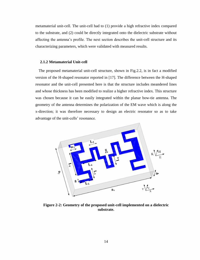
2.1.2 Metamaterial Unit-cell
The proposed metamaterial unit-cell structure, shown in Fig.2.2, is in fact a modified
version of the H-shaped resonator reported in [17]. The difference between the H-shaped
resonator and the unit-cell presented here is that the structure includes meandered lines
and whose thickness has been modified to realize a higher refractive index. This structure
was chosen because it can be easily integrated within the planar bow-tie antenna. The
geometry of the antenna determines the polarization of the EM wave which is along the
x-direction; it was therefore necessary to design an electric resonator so as to take
advantage of the unit-cells‟ resonance.
Figure 2-2: Geometry of the proposed unit-cell implemented on a dielectric
substrate.
15
The H-shaped meandered line structure was fabricated on a Rogers RT5880 substrate
with the thickness of h=1.575 mm, permittivity of 2.2, and loss-tangent of 0.0009. The
dimensions of the unit-cell structure are: ax=6 mm, ay=3.77 mm, w=0.2 mm, w1=0.5 mm,
L1=1.8 mm, L2=1 mm, L3=0.8 mm, L4=1.1 mm, L5=0.6 mm, L6=0.8 mm, g=0.2 mm.
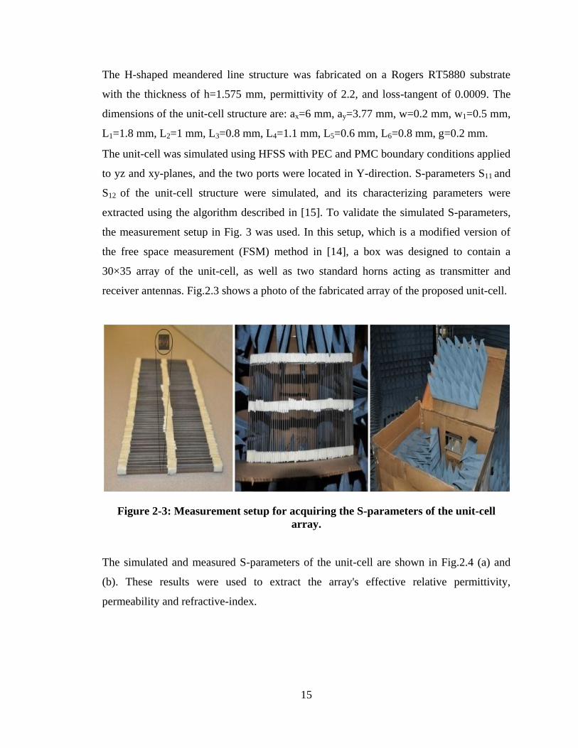
The unit-cell was simulated using HFSS with PEC and PMC boundary conditions applied
to yz and xy-planes, and the two ports were located in Y-direction. S-parameters S11 and
S12 of the unit-cell structure were simulated, and its characterizing parameters were
extracted using the algorithm described in [15]. To validate the simulated S-parameters,
the measurement setup in Fig. 3 was used. In this setup, which is a modified version of
the free space measurement (FSM) method in [14], a box was designed to contain a
30×35 array of the unit-cell, as well as two standard horns acting as transmitter and
receiver antennas. Fig.2.3 shows a photo of the fabricated array of the proposed unit-cell.
Figure 2-3: Measurement setup for acquiring the S-parameters of the unit-cell
array.
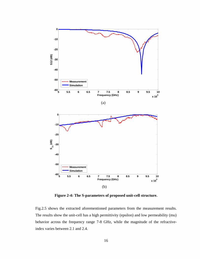
The simulated and measured S-parameters of the unit-cell are shown in Fig.2.4 (a) and
(b). These results were used to extract the array's effective relative permittivity,
permeability and refractive-index.
16
(a)
(b)
Figure 2-4: The S-parameters of proposed unit-cell structure.
Fig.2.5 shows the extracted aforementioned parameters from the measurement results.
The results show the unit-cell has a high permittivity (epsilon) and low permeability (mu)
behavior across the frequency range 7-8 GHz, while the magnitude of the refractive-
index varies between 2.1 and 2.4.
5 5.5 6 6.5 7 7.5 8 8.5 9 9.5 10
x 109
-60
-50
-40
-30
-20
-10
0
Frequency (GHz)
S1
2 (
dB
)
Measurement
Simulation
5 5.5 6 6.5 7 7.5 8 8.5 9 9.5 10
x 109
-60
-50
-40
-30
-20
-10
0
Frequency (GHz)
S1
1 (
dB
)
Measurement
Simulation
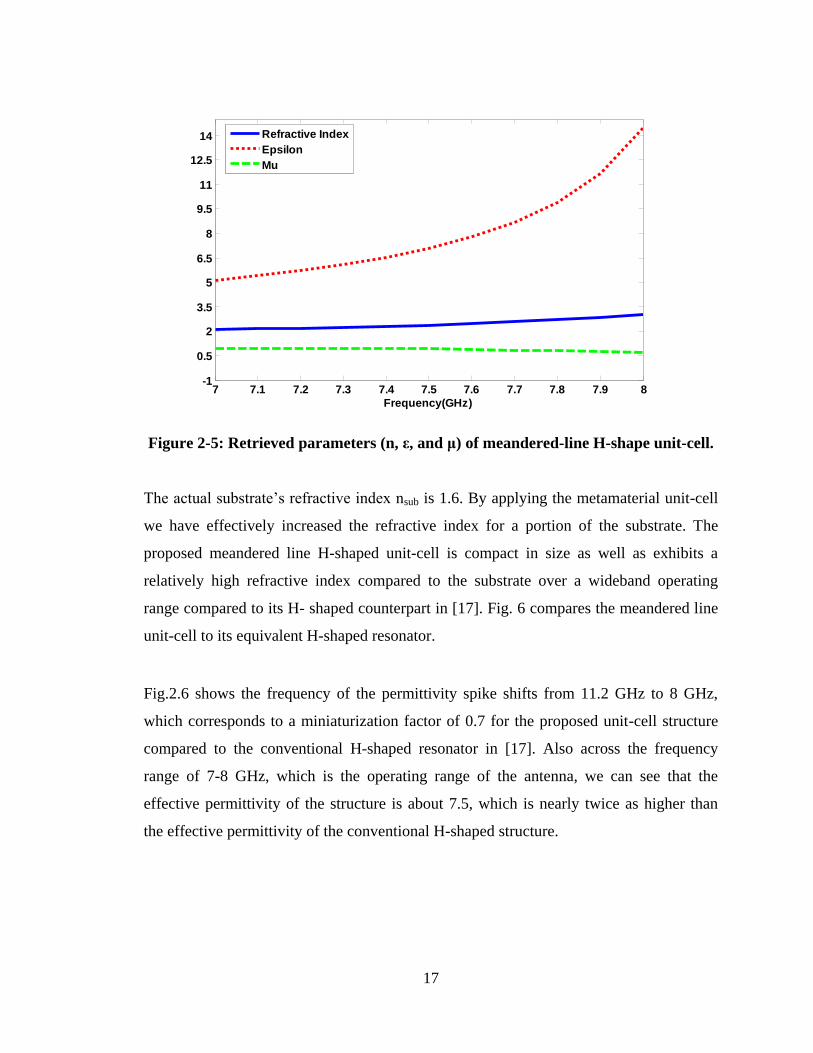
17
Figure 2-5: Retrieved parameters (n, ε, and μ) of meandered-line H-shape unit-cell.
The actual substrate‟s refractive index nsub is 1.6. By applying the metamaterial unit-cell
we have effectively increased the refractive index for a portion of the substrate. The
proposed meandered line H-shaped unit-cell is compact in size as well as exhibits a
relatively high refractive index compared to the substrate over a wideband operating
range compared to its H- shaped counterpart in [17]. Fig. 6 compares the meandered line
unit-cell to its equivalent H-shaped resonator.
Fig.2.6 shows the frequency of the permittivity spike shifts from 11.2 GHz to 8 GHz,
which corresponds to a miniaturization factor of 0.7 for the proposed unit-cell structure
compared to the conventional H-shaped resonator in [17]. Also across the frequency
range of 7-8 GHz, which is the operating range of the antenna, we can see that the
effective permittivity of the structure is about 7.5, which is nearly twice as higher than
the effective permittivity of the conventional H-shaped structure.
7 7.1 7.2 7.3 7.4 7.5 7.6 7.7 7.8 7.9 8-1
0.5
2
3.5
5
6.5
8
9.5
11
12.5
14
Frequency(GHz)
Refractive Index
Epsilon
Mu
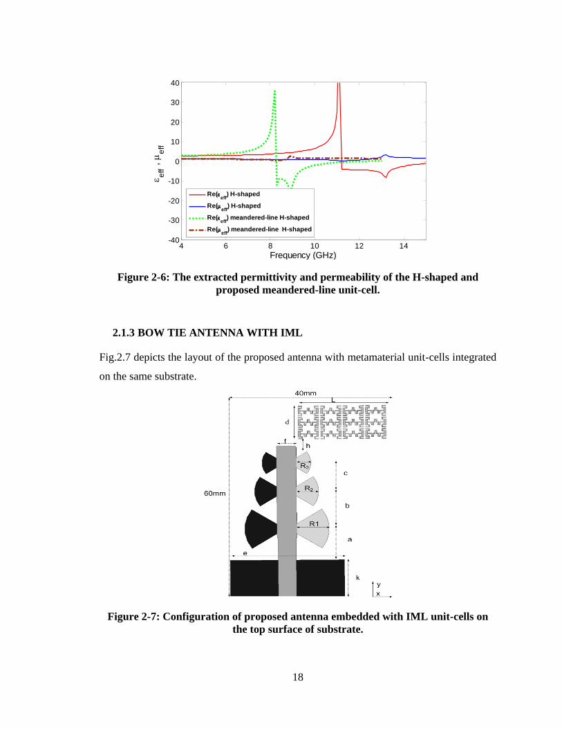
18
Figure 2-6: The extracted permittivity and permeability of the H-shaped and
proposed meandered-line unit-cell.
2.1.3 BOW TIE ANTENNA WITH IML
Fig.2.7 depicts the layout of the proposed antenna with metamaterial unit-cells integrated
on the same substrate.
Figure 2-7: Configuration of proposed antenna embedded with IML unit-cells on
the top surface of substrate.
4 6 8 10 12 14-40
-30
-20
-10
0
10
20
30
40
Frequency (GHz)
e
ff ,
e
ff
Re(eff
) H-shaped
Re(eff
) H-shaped
Re(eff
) meandered-line H-shaped
Re(eff
) meandered-line H-shaped
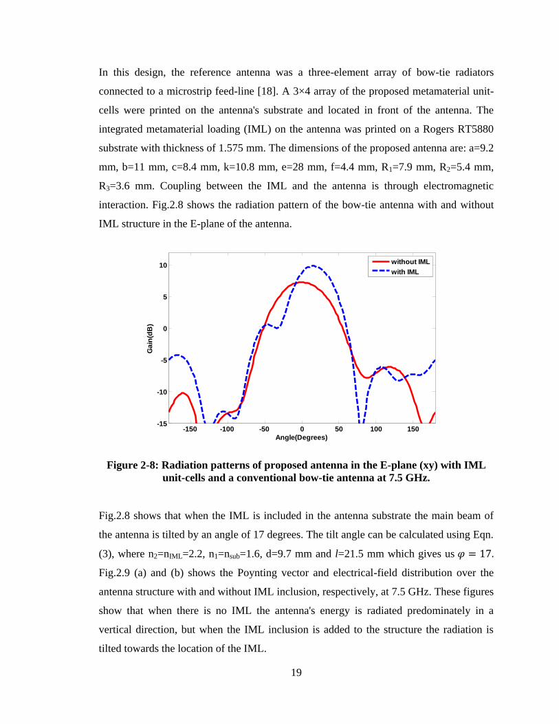
19
In this design, the reference antenna was a three-element array of bow-tie radiators
connected to a microstrip feed-line [18]. A 3×4 array of the proposed metamaterial unit-
cells were printed on the antenna's substrate and located in front of the antenna. The
integrated metamaterial loading (IML) on the antenna was printed on a Rogers RT5880
substrate with thickness of 1.575 mm. The dimensions of the proposed antenna are: a=9.2
mm, b=11 mm, c=8.4 mm, k=10.8 mm, e=28 mm, f=4.4 mm, R1=7.9 mm, R2=5.4 mm,
R3=3.6 mm. Coupling between the IML and the antenna is through electromagnetic
interaction. Fig.2.8 shows the radiation pattern of the bow-tie antenna with and without
IML structure in the E-plane of the antenna.
Figure 2-8: Radiation patterns of proposed antenna in the E-plane (xy) with IML
unit-cells and a conventional bow-tie antenna at 7.5 GHz.
Fig.2.8 shows that when the IML is included in the antenna substrate the main beam of
the antenna is tilted by an angle of 17 degrees. The tilt angle can be calculated using Eqn.
(3), where n2=nIML=2.2, n1=nsub=1.6, d=9.7 mm and l=21.5 mm which gives us 𝜑 = 17.
Fig.2.9 (a) and (b) shows the Poynting vector and electrical-field distribution over the
antenna structure with and without IML inclusion, respectively, at 7.5 GHz. These figures
show that when there is no IML the antenna's energy is radiated predominately in a
vertical direction, but when the IML inclusion is added to the structure the radiation is
tilted towards the location of the IML.
-150 -100 -50 0 50 100 150-15
-10
-5
0
5
10
Angle(Degrees)
Ga
in(d
B)
without IML
with IML
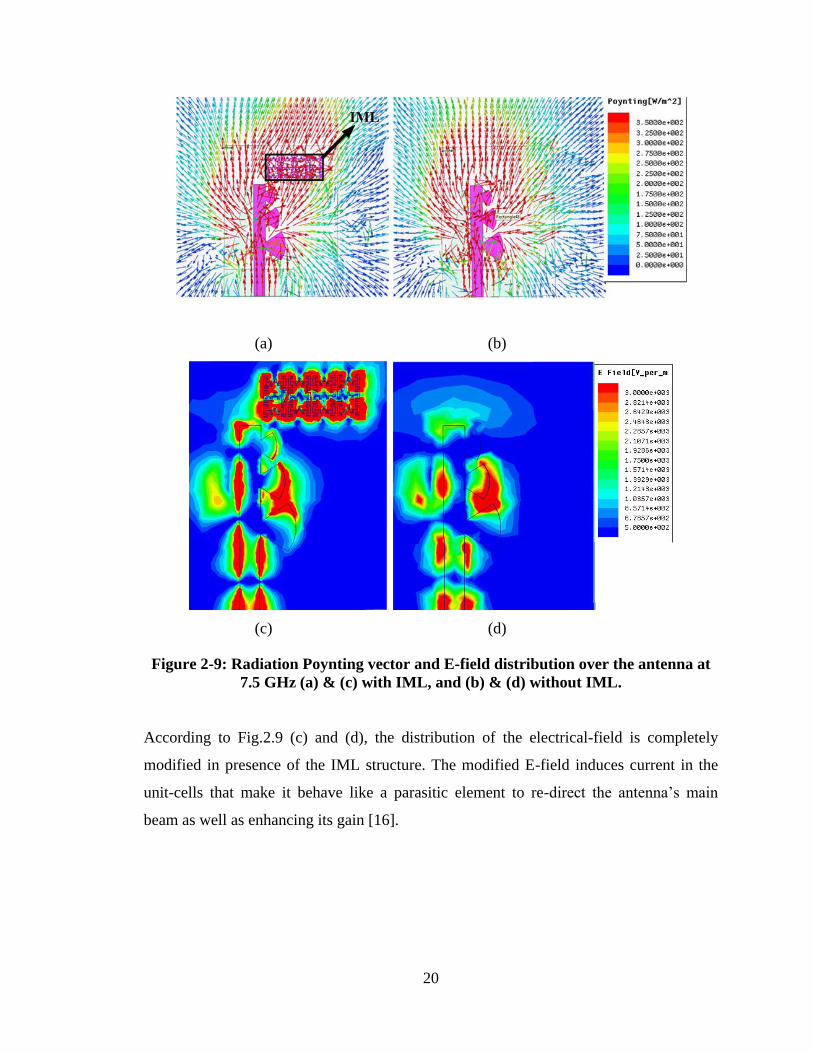
20
(a) (b)
(c) (d)
Figure 2-9: Radiation Poynting vector and E-field distribution over the antenna at
7.5 GHz (a) & (c) with IML, and (b) & (d) without IML.
According to Fig.2.9 (c) and (d), the distribution of the electrical-field is completely
modified in presence of the IML structure. The modified E-field induces current in the
unit-cells that make it behave like a parasitic element to re-direct the antenna‟s main
beam as well as enhancing its gain [16].
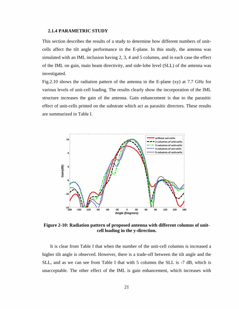
21
2.1.4 PARAMETRIC STUDY
This section describes the results of a study to determine how different numbers of unit-
cells affect the tilt angle performance in the E-plane. In this study, the antenna was
simulated with an IML inclusion having 2, 3, 4 and 5 columns, and in each case the effect
of the IML on gain, main beam directivity, and side-lobe level (SLL) of the antenna was
investigated.
Fig.2.10 shows the radiation pattern of the antenna in the E-plane (xy) at 7.7 GHz for
various levels of unit-cell loading. The results clearly show the incorporation of the IML
structure increases the gain of the antenna. Gain enhancement is due to the parasitic
effect of unit-cells printed on the substrate which act as parasitic directors. These results
are summarized in Table I.
Figure 2-10: Radiation pattern of proposed antenna with different columns of unit-
cell loading in the y-direction.
It is clear from Table I that when the number of the unit-cell columns is increased a
higher tilt angle is observed. However, there is a trade-off between the tilt angle and the
SLL, and as we can see from Table I that with 5 columns the SLL is -7 dB, which is
unacceptable. The other effect of the IML is gain enhancement, which increases with
-180 -150 -120 -90 -60 -30 0 30 60 90 120 150 180-15
-10
-5
0
5
10
Angle (Degrees)
Ga
in(d
B)
without uni-cells
2 columns of unit-cells
3 columns of unit-cells
4 columns of uni-cells
5 columns of unit-cells
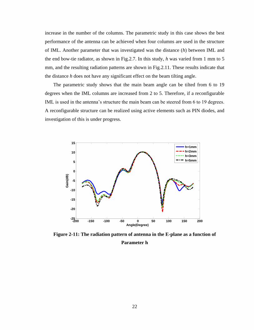
22
increase in the number of the columns. The parametric study in this case shows the best
performance of the antenna can be achieved when four columns are used in the structure
of IML. Another parameter that was investigated was the distance (h) between IML and
the end bow-tie radiator, as shown in Fig.2.7. In this study, h was varied from 1 mm to 5
mm, and the resulting radiation patterns are shown in Fig.2.11. These results indicate that
the distance h does not have any significant effect on the beam tilting angle.
The parametric study shows that the main beam angle can be tilted from 6 to 19
degrees when the IML columns are increased from 2 to 5. Therefore, if a reconfigurable
IML is used in the antenna‟s structure the main beam can be steered from 6 to 19 degrees.
A reconfigurable structure can be realized using active elements such as PIN diodes, and
investigation of this is under progress.
Figure 2-11: The radiation pattern of antenna in the E-plane as a function of
Parameter h
-200 -150 -100 -50 0 50 100 150 200-25
-20
-15
-10
-5
0
5
10
15
Angle(Degree)
Ga
in(d
B)
h=1mm
h=2mm
h=3mm
h=5mm
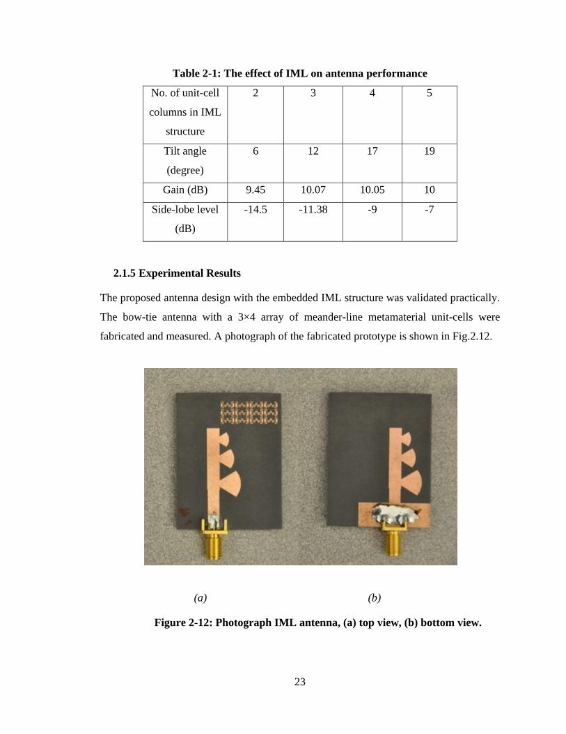
23
Table 2-1: The effect of IML on antenna performance
No. of unit-cell
columns in IML
structure
2 3 4 5
Tilt angle
(degree)
6 12 17 19
Gain (dB) 9.45 10.07 10.05 10
Side-lobe level
(dB)
-14.5 -11.38 -9 -7
2.1.5 Experimental Results
The proposed antenna design with the embedded IML structure was validated practically.
The bow-tie antenna with a 3×4 array of meander-line metamaterial unit-cells were
fabricated and measured. A photograph of the fabricated prototype is shown in Fig.2.12.
(a) (b)
Figure 2-12: Photograph IML antenna, (a) top view, (b) bottom view.
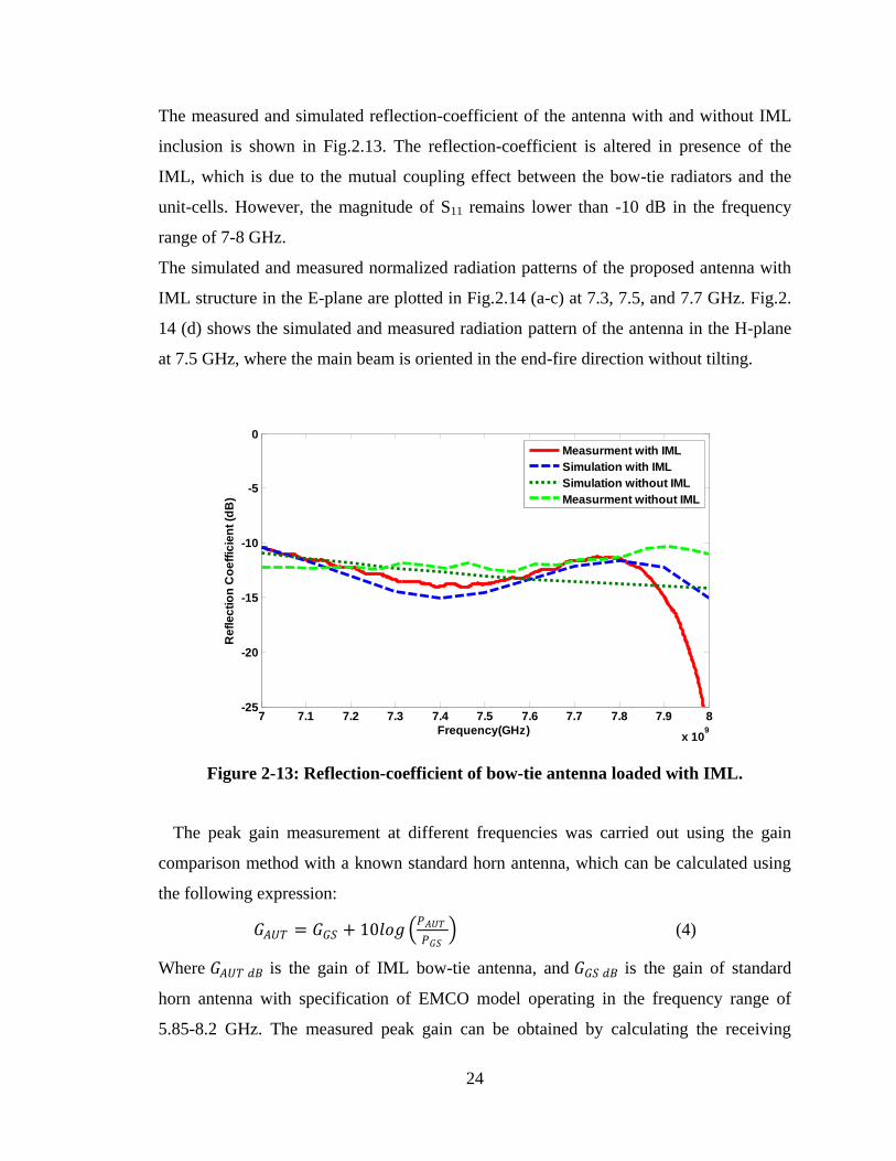
24
The measured and simulated reflection-coefficient of the antenna with and without IML
inclusion is shown in Fig.2.13. The reflection-coefficient is altered in presence of the
IML, which is due to the mutual coupling effect between the bow-tie radiators and the
unit-cells. However, the magnitude of S11 remains lower than -10 dB in the frequency
range of 7-8 GHz.
The simulated and measured normalized radiation patterns of the proposed antenna with
IML structure in the E-plane are plotted in Fig.2.14 (a-c) at 7.3, 7.5, and 7.7 GHz. Fig.2.
14 (d) shows the simulated and measured radiation pattern of the antenna in the H-plane
at 7.5 GHz, where the main beam is oriented in the end-fire direction without tilting.
Figure 2-13: Reflection-coefficient of bow-tie antenna loaded with IML.
The peak gain measurement at different frequencies was carried out using the gain
comparison method with a known standard horn antenna, which can be calculated using
the following expression:
𝐺𝐴𝑈𝑇 = 𝐺𝐺𝑆 + 10𝑙𝑜𝑔 𝑃𝐴𝑈𝑇
𝑃𝐺𝑆 (4)
Where 𝐺𝐴𝑈𝑇 𝑑𝐵 is the gain of IML bow-tie antenna, and 𝐺𝐺𝑆 𝑑𝐵 is the gain of standard
horn antenna with specification of EMCO model operating in the frequency range of
5.85-8.2 GHz. The measured peak gain can be obtained by calculating the receiving
7 7.1 7.2 7.3 7.4 7.5 7.6 7.7 7.8 7.9 8
x 109
-25
-20
-15
-10
-5
0
Frequency(GHz)
Re
fle
cti
on
Co
eff
icie
nt
(dB
)
Measurment with IML
Simulation with IML
Simulation without IML
Measurment without IML
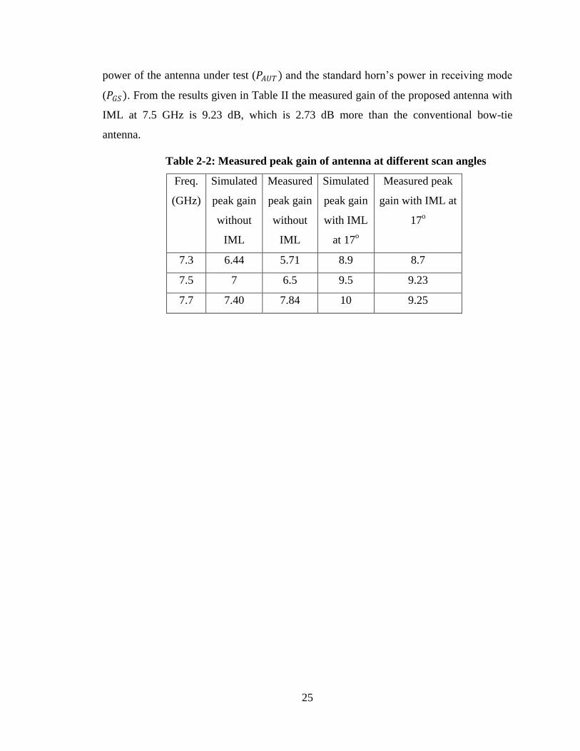
25
power of the antenna under test (𝑃𝐴𝑈𝑇) and the standard horn‟s power in receiving mode
(𝑃𝐺𝑆). From the results given in Table II the measured gain of the proposed antenna with
IML at 7.5 GHz is 9.23 dB, which is 2.73 dB more than the conventional bow-tie
antenna.
Table 2-2: Measured peak gain of antenna at different scan angles
Freq.
(GHz)
Simulated
peak gain
without
IML
Measured
peak gain
without
IML
Simulated
peak gain
with IML
at 17o
Measured peak
gain with IML at
17o
7.3 6.44 5.71 8.9 8.7
7.5 7 6.5 9.5 9.23
7.7 7.40 7.84 10 9.25
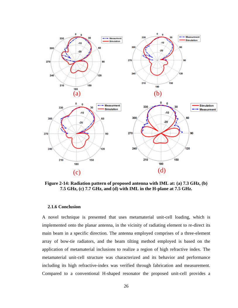
26
(a) (b)
(c) (d)
Figure 2-14: Radiation pattern of proposed antenna with IML at: (a) 7.3 GHz, (b)
7.5 GHz, (c) 7.7 GHz, and (d) with IML in the H-plane at 7.5 GHz.
2.1.6 Conclusion
A novel technique is presented that uses metamaterial unit-cell loading, which is
implemented onto the planar antenna, in the vicinity of radiating element to re-direct its
main beam in a specific direction. The antenna employed comprises of a three-element
array of bow-tie radiators, and the beam tilting method employed is based on the
application of metamaterial inclusions to realize a region of high refractive index. The
metamaterial unit-cell structure was characterized and its behavior and performance
including its high refractive-index was verified through fabrication and measurement.
Compared to a conventional H-shaped resonator the proposed unit-cell provides a
27
miniaturization factor of 0.7 as well as a higher refractive-index. A 3×4 array of
metamaterial unit-cell loading was integrated within a bow-tie antenna. The simulation
and experimental results show that the antenna's main beam tilted by 17 degrees in a
direction towards the location of the metamaterial loading in the E-plane, while the H-
plane radiation pattern remains unchanged. The tilt angle observed correlates with the
predicted value. Unlike other conventional methods of tilting, the method described here
results in no degradation in gain, in fact a gain enhancement of 2.73 dB is observed,
which is due to parasitic behavior of the metamaterial unit-cell inclusion.
28
Chapter 3 RADIATION BEAM TILTING OF END-FIRE
ANTENNA WITH META-SURFACE
3.1 Introduction
Adaptive antennas with beam-steering capability provide advantages of increased signal
gain, greater range of the signal path, reduced multipath reflection, improved spectral
efficiency, and increased network capacity. Various techniques have been reported to
steer the direction of the main beam of planar antennas including RF varactor diodes [19]
and RF MEMS phase shifter [20]. When these techniques are implemented in array
antennas the associated large loss renders them unsuitable for applications especially at
millimeter-wave bands. The direction of the main beam can be steered mechanically
however this is undesirable for numerous applications. More recently, the authors in [1]
have incorporated an electromagnetic band-gap (EBG) structure in the orthogonal plane
around an array of four printed dipole antennas. With this technique the EBG structure
needs to be placed in close proximity to the dipole antennas in order to tilt the direction
of the antenna‟s main beam by 28 degrees at 3.5 GHz. Although the technique is simple it
requires each conductor element constituting the EBG unit-cell to be short-circuited to
ground, which can complicate its construction and impact on the cost of the antenna. To
circumvent this shortfall the authors in [21] have demonstrated that by loading a bow-tie
antenna with an array of sub-wavelength meander-line metamaterial unit-cells can tilt the
main beam of the antenna by 17 degree in the azimuth plane over 7.2-7.5 GHz. Greater
tilt angle has be reported by the same authors in [22] using gradient index of refraction
implemented with metamaterial unit-cells that are integrated in the azimuth plane of
printed dipole antenna. They have shown the direction of the main beam can be deflected
by 26 degrees in the E-plane at millimeter-wave frequencies. This technique offers a low-
profile structure with good gain and tilt angle. To obtain a beam deflection of 30 degrees
in the elevation plane at 60 GHz the authors in [23] employed an array of folded H-
shaped resonators.
In this chapter meta-surface is used to tilt the direction of the bow-tie antenna, where the
meta-surface is realized by magnetic resonance created with split-ring resonators (SRR).
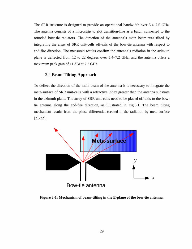
29
The SRR structure is designed to provide an operational bandwidth over 5.4–7.5 GHz.
The antenna consists of a microstrip to slot transition-line as a balun connected to the
rounded bow-tie radiators. The direction of the antenna‟s main beam was tilted by
integrating the array of SRR unit-cells off-axis of the bow-tie antenna with respect to
end-fire direction. The measured results confirm the antenna‟s radiation in the azimuth
plane is deflected from 12 to 22 degrees over 5.4–7.2 GHz, and the antenna offers a
maximum peak gain of 11 dBi at 7.2 GHz.
3.2 Beam Tilting Approach
To deflect the direction of the main beam of the antenna it is necessary to integrate the
meta-surface of SRR unit-cells with a refractive index greater than the antenna substrate
in the azimuth plane. The array of SRR unit-cells need to be placed off-axis to the bow-
tie antenna along the end-fire direction, as illustrated in Fig.3.1. The beam tilting
mechanism results from the phase differential created in the radiation by meta-surface
[21-22].
Meta-surface
x
y
Bow-tie antenna
Figure 3-1: Mechanism of beam-tilting in the E-plane of the bow-tie antenna.
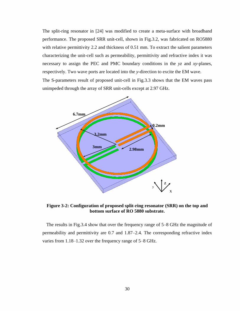
30
The split-ring resonator in [24] was modified to create a meta-surface with broadband
performance. The proposed SRR unit-cell, shown in Fig.3.2, was fabricated on RO5880
with relative permittivity 2.2 and thickness of 0.51 mm. To extract the salient parameters
characterizing the unit-cell such as permeability, permittivity and refractive index it was
necessary to assign the PEC and PMC boundary conditions in the yz and xy-planes,
respectively. Two wave ports are located into the y-direction to excite the EM wave.
The S-parameters result of proposed unit-cell in Fig.3.3 shows that the EM waves pass
unimpeded through the array of SRR unit-cells except at 2.97 GHz.
X
yZ
2.98mm3mm
3.2mm
0.2mm
6.7mm
Figure 3-2: Configuration of proposed split-ring resonator (SRR) on the top and
bottom surface of RO 5880 substrate.
The results in Fig.3.4 show that over the frequency range of 5–8 GHz the magnitude of
permeability and permittivity are 0.7 and 1.87–2.4. The corresponding refractive index
varies from 1.18–1.32 over the frequency range of 5–8 GHz.
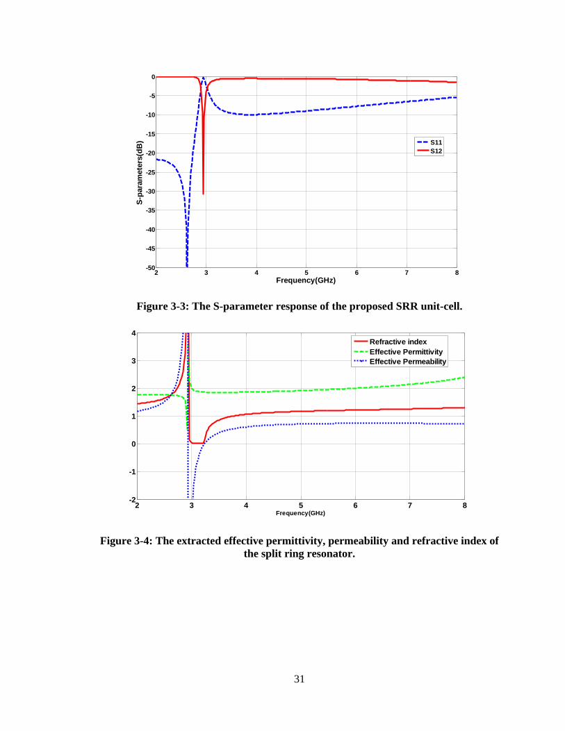
31
Figure 3-3: The S-parameter response of the proposed SRR unit-cell.
Figure 3-4: The extracted effective permittivity, permeability and refractive index of
the split ring resonator.
2 3 4 5 6 7 8-50
-45
-40
-35
-30
-25
-20
-15
-10
-5
0
Frequency(GHz)
S-p
ara
mete
rs(d
B)
S11
S12
2 3 4 5 6 7 8-2
-1
0
1
2
3
4
Frequency(GHz)
Refractive index
Effective Permittivity
Effective Permeability
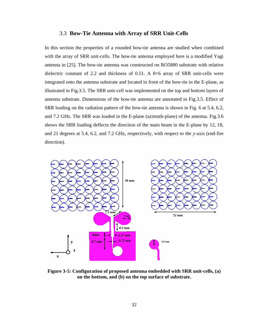
32
3.3 Bow-Tie Antenna with Array of SRR Unit-Cells
In this section the properties of a rounded bow-tie antenna are studied when combined
with the array of SRR unit-cells. The bow-tie antenna employed here is a modified Yagi
antenna in [25]. The bow-tie antenna was constructed on RO5880 substrate with relative
dielectric constant of 2.2 and thickness of 0.51. A 8×6 array of SRR unit-cells were
integrated onto the antenna substrate and located in front of the bow-tie in the E-plane, as
illustrated in Fig.3.5. The SRR unit-cell was implemented on the top and bottom layers of
antenna substrate. Dimensions of the bow-tie antenna are annotated in Fig.3.5. Effect of
SRR loading on the radiation pattern of the bow-tie antenna is shown in Fig. 6 at 5.4, 6.2,
and 7.2 GHz. The SRR was loaded in the E-plane (azimuth-plane) of the antenna. Fig.3.6
shows the SRR loading deflects the direction of the main beam in the E-plane by 12, 18,
and 21 degrees at 5.4, 6.2, and 7.2 GHz, respectively, with respect to the y-axis (end-fire
direction).
(a) (b)
52 mm
39 mm
3.9 mm
7.5 mm
8.3 mm
2.27 mm
0.72 mm
7 mm
x
y
z
4mm
8.7 mm
Figure 3-5: Configuration of proposed antenna embedded with SRR unit-cells, (a)
on the bottom, and (b) on the top surface of substrate.
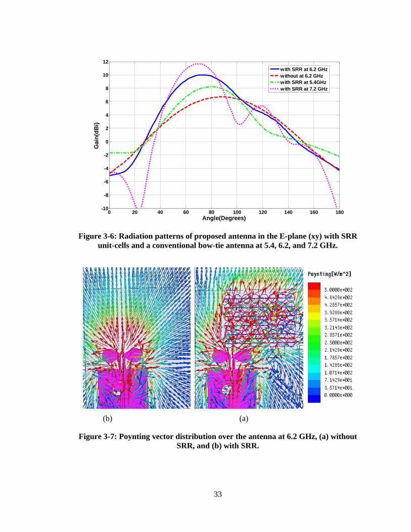
33
Figure 3-6: Radiation patterns of proposed antenna in the E-plane (xy) with SRR
unit-cells and a conventional bow-tie antenna at 5.4, 6.2, and 7.2 GHz.
(a) (b)
(b) (a)
Figure 3-7: Poynting vector distribution over the antenna at 6.2 GHz, (a) without
SRR, and (b) with SRR.
0 20 40 60 80 100 120 140 160 180-10
-8
-6
-4
-2
0
2
4
6
8
10
12
Angle(Degrees)
Gain
(dB
i)
with SRR at 6.2 GHz
without at 6.2 GHz
with SRR at 5.4GHz
with SRR at 7.2 GHz
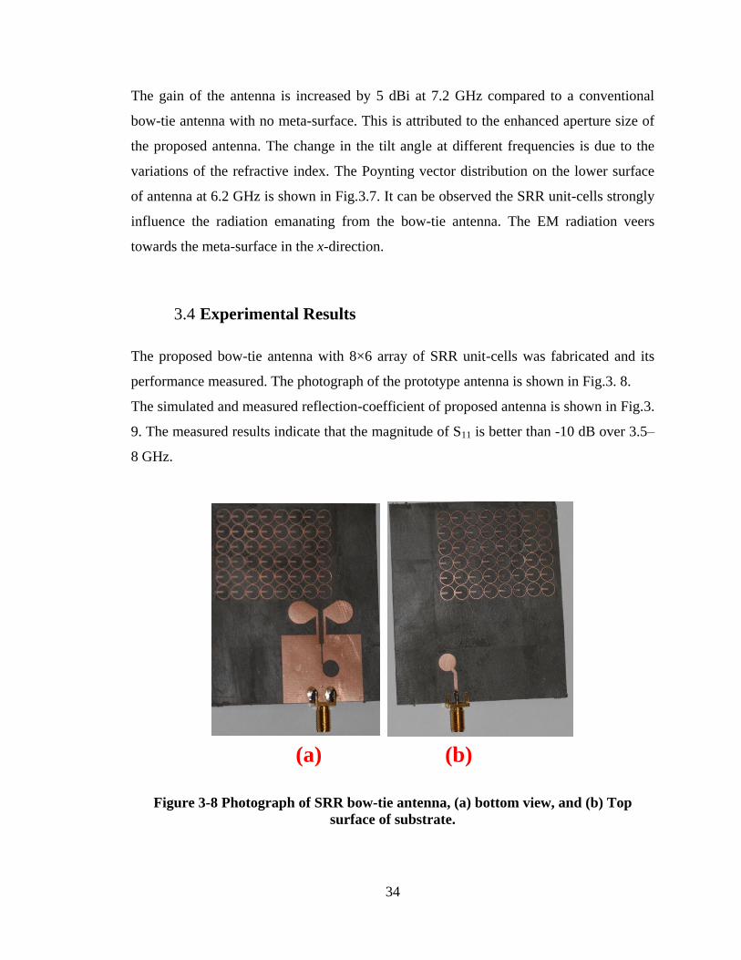
34
The gain of the antenna is increased by 5 dBi at 7.2 GHz compared to a conventional
bow-tie antenna with no meta-surface. This is attributed to the enhanced aperture size of
the proposed antenna. The change in the tilt angle at different frequencies is due to the
variations of the refractive index. The Poynting vector distribution on the lower surface
of antenna at 6.2 GHz is shown in Fig.3.7. It can be observed the SRR unit-cells strongly
influence the radiation emanating from the bow-tie antenna. The EM radiation veers
towards the meta-surface in the x-direction.
3.4 Experimental Results
The proposed bow-tie antenna with 8×6 array of SRR unit-cells was fabricated and its
performance measured. The photograph of the prototype antenna is shown in Fig.3. 8.
The simulated and measured reflection-coefficient of proposed antenna is shown in Fig.3.
9. The measured results indicate that the magnitude of S11 is better than -10 dB over 3.5–
8 GHz.
(a) (b)
Figure 3-8 Photograph of SRR bow-tie antenna, (a) bottom view, and (b) Top
surface of substrate.
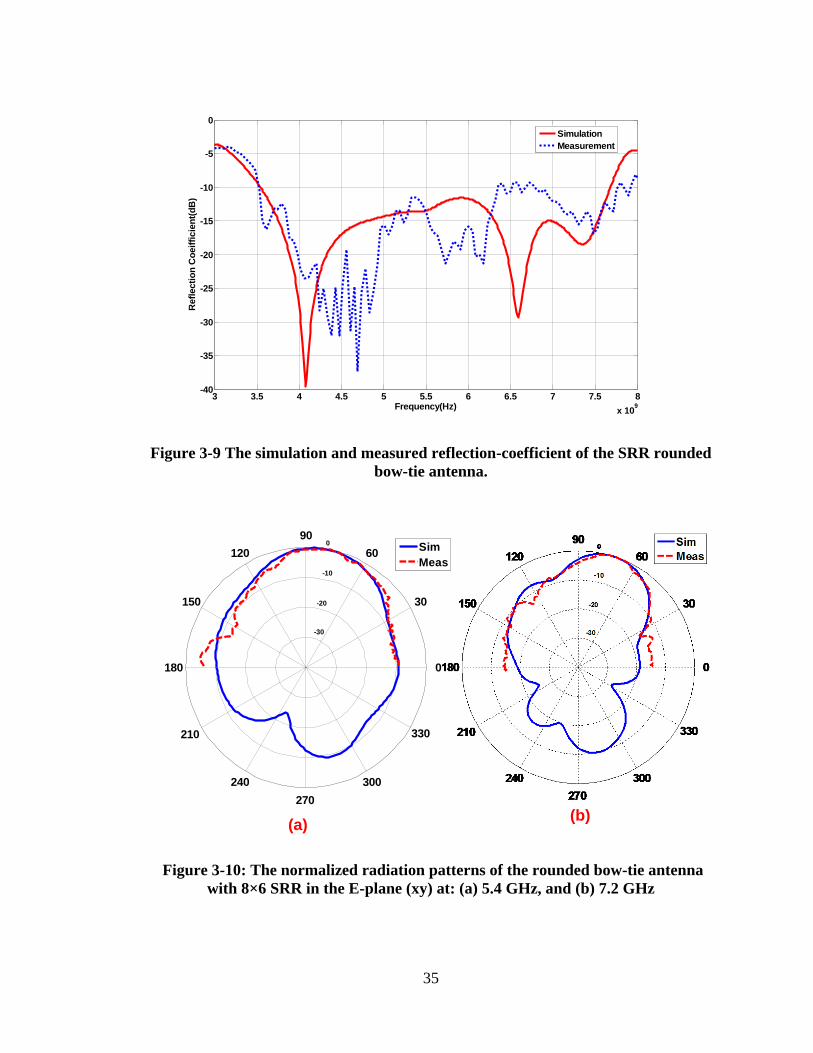
35
Figure 3-9 The simulation and measured reflection-coefficient of the SRR rounded
bow-tie antenna.
(a)(b)
-30
-20
-10
0
30
210
60
240
90
270
120
300
150
330
180 0
Sim
Meas
Figure 3-10: The normalized radiation patterns of the rounded bow-tie antenna
with 8×6 SRR in the E-plane (xy) at: (a) 5.4 GHz, and (b) 7.2 GHz
3 3.5 4 4.5 5 5.5 6 6.5 7 7.5 8
x 109
-40
-35
-30
-25
-20
-15
-10
-5
0
Frequency(Hz)
Refl
ecti
on
Co
eif
ficie
nt(
dB
)
Simulation
Measurement
36
The simulated and measured radiation pattern of the proposed antenna in the E-plane (xy)
at 5.4 and 7.4 GHz, in Fig.3.10, shows the direction of the antenna‟s main beam is
deflected by 12 and 21 degrees at 5.4 and 7.2 GHz, respectively. The change in the
deflection angle at the two frequencies is attributed to the variation in the refractive index
of the meta-surface as in Fig.3.4. The measured antenna gain at 5.4 and 7.2 GHz are 8.2
and 11 dBi, respectively.
3.5 Conclusion
Meta-surface created with magnetic resonance using an array of split-ring resonators was
employed to steer the direction of a bow-tie antenna‟s main beam in a predefined angle.
The meta-surface comprised 8×6 array of split-ring resonators that were integrated on the
bow-tie antenna. The measured results validate the proposed technique. Beam deflection
of 12 and 21 degrees were achieved at 5.4 and 7.2 GHz, respectively, with a
corresponding maximum peak gain of 8.1 and 11 dBi.
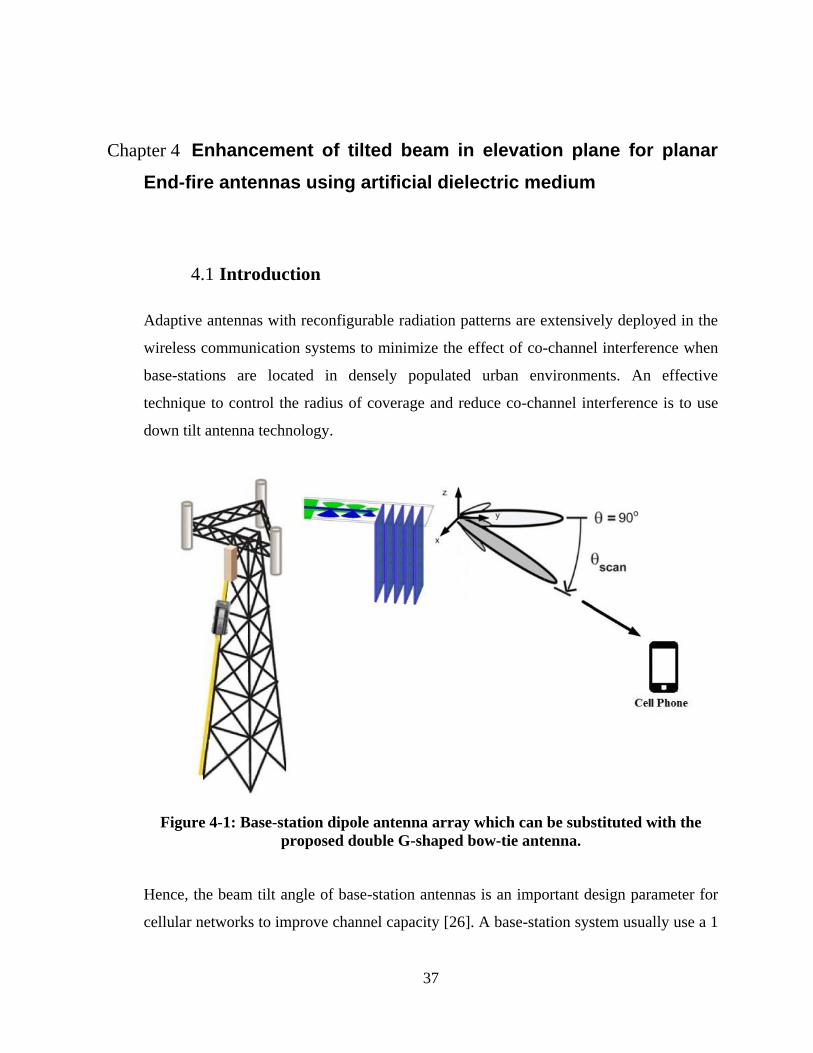
37
Chapter 4 Enhancement of tilted beam in elevation plane for planar
End-fire antennas using artificial dielectric medium
4.1 Introduction
Adaptive antennas with reconfigurable radiation patterns are extensively deployed in the
wireless communication systems to minimize the effect of co-channel interference when
base-stations are located in densely populated urban environments. An effective
technique to control the radius of coverage and reduce co-channel interference is to use
down tilt antenna technology.
Figure 4-1: Base-station dipole antenna array which can be substituted with the
proposed double G-shaped bow-tie antenna.
Hence, the beam tilt angle of base-station antennas is an important design parameter for
cellular networks to improve channel capacity [26]. A base-station system usually use a 1
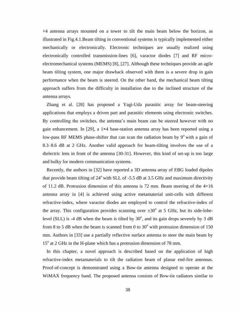
38
×4 antenna arrays mounted on a tower to tilt the main beam below the horizon, as
illustrated in Fig.4.1.Beam tilting in conventional systems is typically implemented either
mechanically or electronically. Electronic techniques are usually realized using
electronically controlled transmission-lines [6], varactor diodes [7] and RF micro-
electromechanical systems (MEMS) [8], [27]. Although these techniques provide an agile
beam tilting system, one major drawback observed with them is a severe drop in gain
performance when the beam is steered. On the other hand, the mechanical beam tilting
approach suffers from the difficulty in installation due to the inclined structure of the
antenna arrays.
Zhang et al. [28] has proposed a Yagi-Uda parasitic array for beam-steering
applications that employs a driven part and parasitic elements using electronic switches.
By controlling the switches, the antenna‟s main beam can be steered however with no
gain enhancement. In [29], a 1×4 base-station antenna array has been reported using a
low-pass RF MEMS phase-shifter that can scan the radiation beam by 9o
with a gain of
8.3–8.6 dB at 2 GHz. Another valid approach for beam-tilting involves the use of a
dielectric lens in front of the antenna [30-31]. However, this kind of set-up is too large
and bulky for modern communication systems.
Recently, the authors in [32] have reported a 3D antenna array of EBG loaded dipoles
that provide beam tilting of 24o
with SLL of -5.5 dB at 3.5 GHz and maximum directivity
of 11.2 dB. Protrusion dimension of this antenna is 72 mm. Beam steering of the 4×16
antenna array in [4] is achieved using active metamaterial unit-cells with different
refractive-index, where varactor diodes are employed to control the refractive-index of
the array. This configuration provides scanning over ±30o at 5 GHz, but its side-lobe-
level (SLL) is -4 dB when the beam is tilted by 30o, and its gain drops severely by 3 dB
from 8 to 5 dB when the beam is scanned from 0 to 30o with protrusion dimension of 150
mm. Authors in [33] use a partially reflective surface antenna to steer the main beam by
15o at 2 GHz in the H-plane which has a protrusion dimension of 78 mm.
In this chapter, a novel approach is described based on the application of high
refractive-index metamaterials to tilt the radiation beam of planar end-fire antennas.
Proof-of-concept is demonstrated using a Bow-tie antenna designed to operate at the
WiMAX frequency band. The proposed antenna consists of Bow-tie radiators similar to
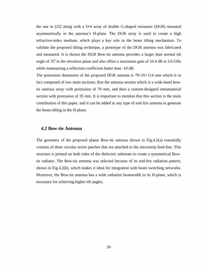
39
the one in [25] along with a 5×4 array of double G-shaped resonator (DGR) mounted
asymmetrically in the antenna‟s H-plane. The DGR array is used to create a high
refractive-index medium, which plays a key role in the beam tilting mechanism. To
validate the proposed tilting technique, a prototype of the DGR antenna was fabricated
and measured. It is shown the DGR Bow-tie antenna provides a larger than normal tilt
angle of 35o in the elevation plane and also offers a maximum gain of 10.4 dB at 3.6 GHz
while maintaining a reflection-coefficient better than -10 dB.
The protrusion dimension of the proposed DGR antenna is 79+35=114 mm which is in
fact composed of two main sections: first the antenna section which is a wide-band bow-
tie antenna array with protrusion of 79 mm, and then a custom-designed metamaterial
section with protrusion of 35 mm. It is important to mention that this section is the main
contribution of this paper, and it can be added to any type of end-fire antenna to generate
the beam-tilting in the H-plane.
4.2 Bow-tie Antenna
The geometry of the proposed planar Bow-tie antenna shown in Fig.4.2(a) essentially
consists of three circular sector patches that are attached to the microstrip feed-line. This
structure is printed on both sides of the dielectric substrate to create a symmetrical Bow-
tie radiator. The Bow-tie antenna was selected because of its end-fire radiation pattern,
shown in Fig.4.2(b), which makes it ideal for integration with beam switching networks.
Moreover, the Bow-tie antenna has a wide radiation beamwidth in its H-plane, which is
necessary for achieving higher tilt angles.
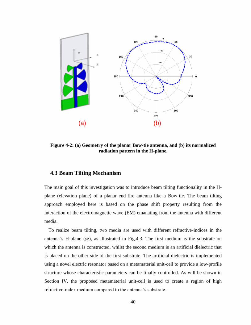
40
-20
-10
0
30
210
60
240
90
270
120
300
150
330
180 0
(a) (b)
Figure 4-2: (a) Geometry of the planar Bow-tie antenna, and (b) its normalized
radiation pattern in the H-plane.
4.3 Beam Tilting Mechanism
The main goal of this investigation was to introduce beam tilting functionality in the H-
plane (elevation plane) of a planar end-fire antenna like a Bow-tie. The beam tilting
approach employed here is based on the phase shift property resulting from the
interaction of the electromagnetic wave (EM) emanating from the antenna with different
media.
To realize beam tilting, two media are used with different refractive-indices in the
antenna‟s H-plane (yz), as illustrated in Fig.4.3. The first medium is the substrate on
which the antenna is constructed, whilst the second medium is an artificial dielectric that
is placed on the other side of the first substrate. The artificial dielectric is implemented
using a novel electric resonator based on a metamaterial unit-cell to provide a low-profile
structure whose characteristic parameters can be finally controlled. As will be shown in
Section IV, the proposed metamaterial unit-cell is used to create a region of high
refractive-index medium compared to the antenna‟s substrate.
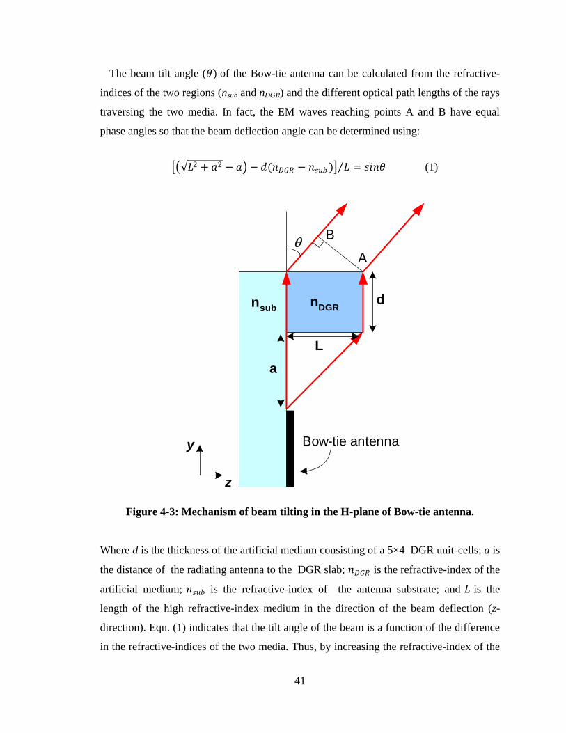
41
The beam tilt angle (𝜃) of the Bow-tie antenna can be calculated from the refractive-
indices of the two regions (nsub and nDGR) and the different optical path lengths of the rays
traversing the two media. In fact, the EM waves reaching points A and B have equal
phase angles so that the beam deflection angle can be determined using:
𝐿2 + 𝑎2 − 𝑎 − 𝑑(𝑛𝐷𝐺𝑅 − 𝑛𝑠𝑢𝑏 ) 𝐿 = 𝑠𝑖𝑛𝜃 (1)
A
B
d
L
a
Bow-tie antennay
z
nsub
nDGR
Figure 4-3: Mechanism of beam tilting in the H-plane of Bow-tie antenna.
Where d is the thickness of the artificial medium consisting of a 5×4 DGR unit-cells; a is
the distance of the radiating antenna to the DGR slab; 𝑛𝐷𝐺𝑅 is the refractive-index of the
artificial medium; 𝑛𝑠𝑢𝑏 is the refractive-index of the antenna substrate; and 𝐿 is the
length of the high refractive-index medium in the direction of the beam deflection (z-
direction). Eqn. (1) indicates that the tilt angle of the beam is a function of the difference
in the refractive-indices of the two media. Thus, by increasing the refractive-index of the
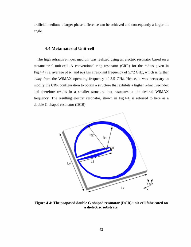
42
artificial medium, a larger phase difference can be achieved and consequently a larger tilt
angle.
4.4 Metamaterial Unit-cell
The high refractive-index medium was realized using an electric resonator based on a
metamaterial unit-cell. A conventional ring resonator (CRR) for the radius given in
Fig.4.4 (i.e. average of R1 and R2) has a resonant frequency of 5.72 GHz, which is further
away from the WiMAX operating frequency of 3.5 GHz. Hence, it was necessary to
modify the CRR configuration to obtain a structure that exhibits a higher refractive-index
and therefore results in a smaller structure that resonates at the desired WiMAX
frequency. The resulting electric resonator, shown in Fig.4.4, is referred to here as a
double G-shaped resonator (DGR).
Figure 4-4: The proposed double G-shaped resonator (DGR) unit-cell fabricated on
a dielectric substrate.
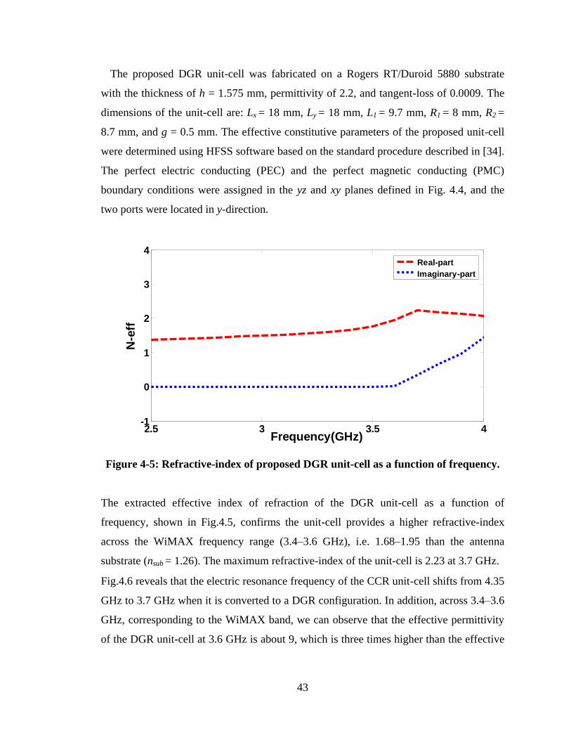
43
The proposed DGR unit-cell was fabricated on a Rogers RT/Duroid 5880 substrate
with the thickness of h = 1.575 mm, permittivity of 2.2, and tangent-loss of 0.0009. The
dimensions of the unit-cell are: Lx = 18 mm, Ly = 18 mm, L1 = 9.7 mm, R1 = 8 mm, R2 =
8.7 mm, and g = 0.5 mm. The effective constitutive parameters of the proposed unit-cell
were determined using HFSS software based on the standard procedure described in [34].
The perfect electric conducting (PEC) and the perfect magnetic conducting (PMC)
boundary conditions were assigned in the yz and xy planes defined in Fig. 4.4, and the
two ports were located in y-direction.
Figure 4-5: Refractive-index of proposed DGR unit-cell as a function of frequency.
The extracted effective index of refraction of the DGR unit-cell as a function of
frequency, shown in Fig.4.5, confirms the unit-cell provides a higher refractive-index
across the WiMAX frequency range (3.4–3.6 GHz), i.e. 1.68–1.95 than the antenna
substrate (nsub = 1.26). The maximum refractive-index of the unit-cell is 2.23 at 3.7 GHz.
Fig.4.6 reveals that the electric resonance frequency of the CCR unit-cell shifts from 4.35
GHz to 3.7 GHz when it is converted to a DGR configuration. In addition, across 3.4–3.6
GHz, corresponding to the WiMAX band, we can observe that the effective permittivity
of the DGR unit-cell at 3.6 GHz is about 9, which is three times higher than the effective
2.5 3 3.5 4-1
0
1
2
3
4
Frequency(GHz)
N-e
ff
Real-part
Imaginary-part
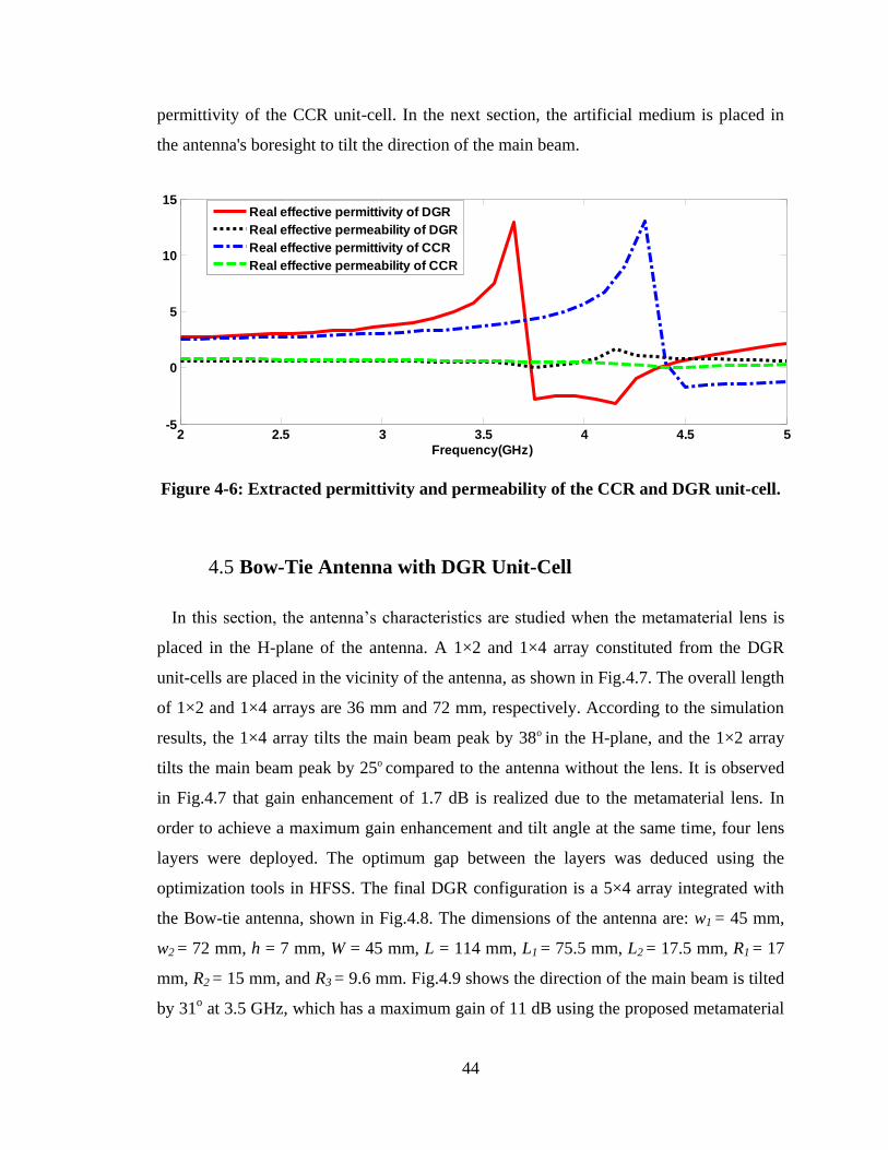
44
permittivity of the CCR unit-cell. In the next section, the artificial medium is placed in
the antenna's boresight to tilt the direction of the main beam.
Figure 4-6: Extracted permittivity and permeability of the CCR and DGR unit-cell.
4.5 Bow-Tie Antenna with DGR Unit-Cell
In this section, the antenna‟s characteristics are studied when the metamaterial lens is
placed in the H-plane of the antenna. A 1×2 and 1×4 array constituted from the DGR
unit-cells are placed in the vicinity of the antenna, as shown in Fig.4.7. The overall length
of 1×2 and 1×4 arrays are 36 mm and 72 mm, respectively. According to the simulation
results, the 1×4 array tilts the main beam peak by 38o in the H-plane, and the 1×2 array
tilts the main beam peak by 25o compared to the antenna without the lens. It is observed
in Fig.4.7 that gain enhancement of 1.7 dB is realized due to the metamaterial lens. In
order to achieve a maximum gain enhancement and tilt angle at the same time, four lens
layers were deployed. The optimum gap between the layers was deduced using the
optimization tools in HFSS. The final DGR configuration is a 5×4 array integrated with
the Bow-tie antenna, shown in Fig.4.8. The dimensions of the antenna are: w1 = 45 mm,
w2 = 72 mm, h = 7 mm, W = 45 mm, L = 114 mm, L1 = 75.5 mm, L2 = 17.5 mm, R1 = 17
mm, R2 = 15 mm, and R3 = 9.6 mm. Fig.4.9 shows the direction of the main beam is tilted
by 31o at 3.5 GHz, which has a maximum gain of 11 dB using the proposed metamaterial
2 2.5 3 3.5 4 4.5 5-5
0
5
10
15
Frequency(GHz)
Real effective permittivity of DGR
Real effective permeability of DGR
Real effective permittivity of CCR
Real effective permeability of CCR
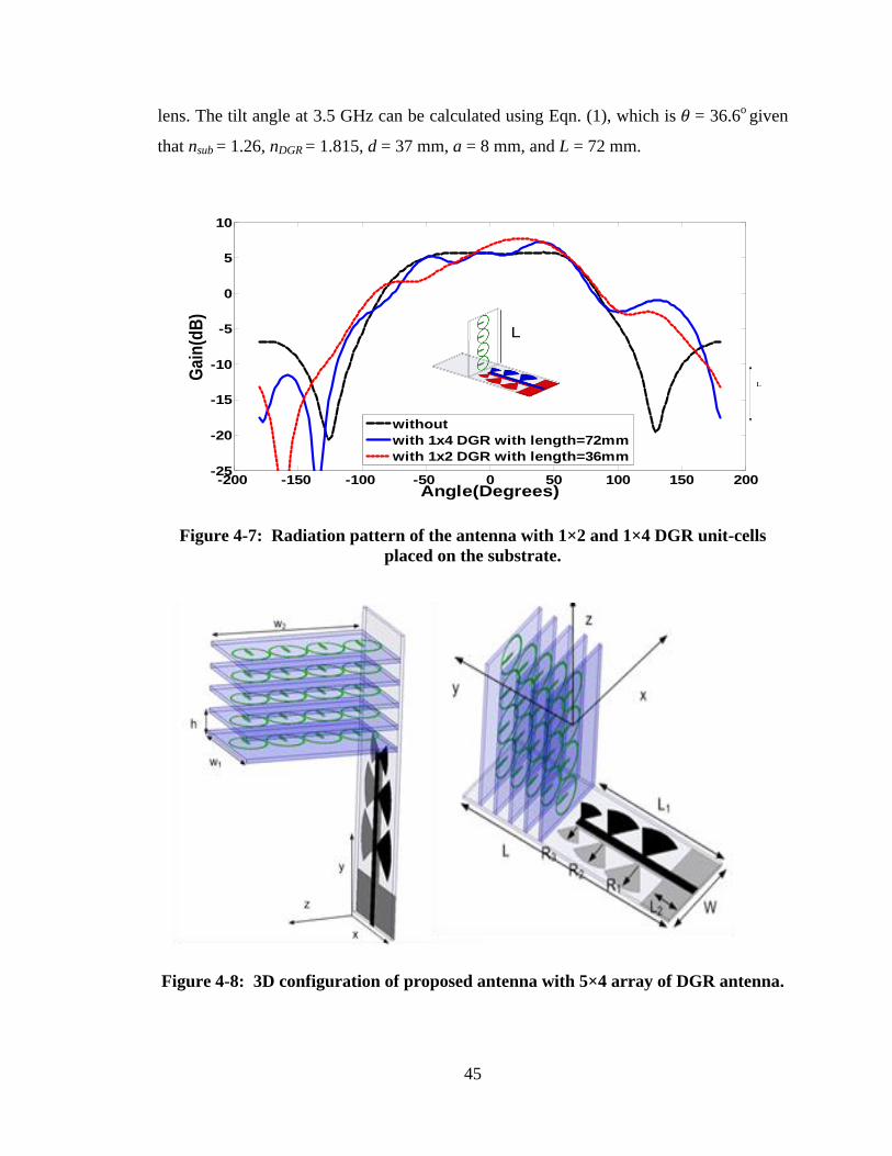
45
lens. The tilt angle at 3.5 GHz can be calculated using Eqn. (1), which is 𝜃 = 36.6o
given
that nsub = 1.26, nDGR = 1.815, d = 37 mm, a = 8 mm, and L = 72 mm.
L
L
-200 -150 -100 -50 0 50 100 150 200-25
-20
-15
-10
-5
0
5
10
Angle(Degrees)
Ga
in(d
B)
without
with 1x4 DGR with length=72mm
with 1x2 DGR with length=36mm
L
Figure 4-7: Radiation pattern of the antenna with 1×2 and 1×4 DGR unit-cells
placed on the substrate.
Figure 4-8: 3D configuration of proposed antenna with 5×4 array of DGR antenna.
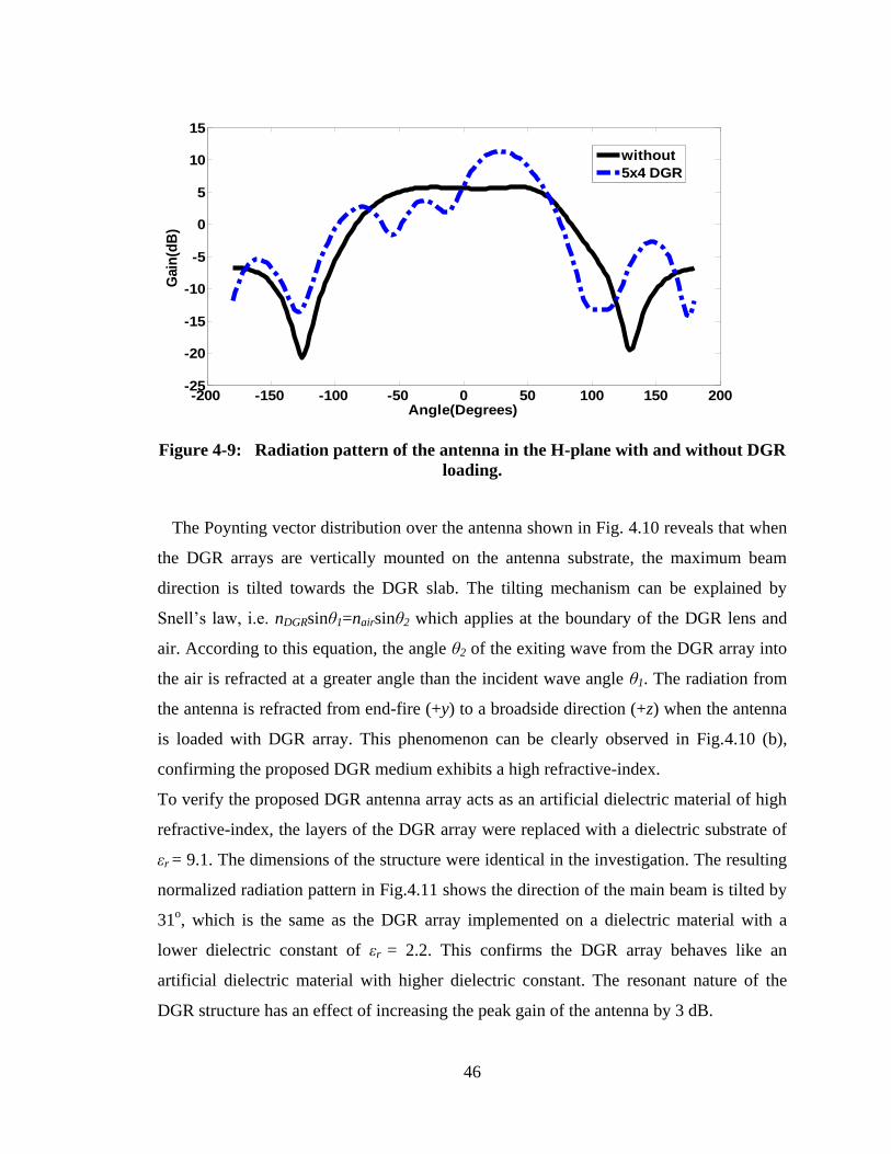
46
Figure 4-9: Radiation pattern of the antenna in the H-plane with and without DGR
loading.
The Poynting vector distribution over the antenna shown in Fig. 4.10 reveals that when
the DGR arrays are vertically mounted on the antenna substrate, the maximum beam
direction is tilted towards the DGR slab. The tilting mechanism can be explained by
Snell‟s law, i.e. nDGRsinθ1=nairsinθ2 which applies at the boundary of the DGR lens and
air. According to this equation, the angle θ2 of the exiting wave from the DGR array into
the air is refracted at a greater angle than the incident wave angle θ1. The radiation from
the antenna is refracted from end-fire (+y) to a broadside direction (+z) when the antenna
is loaded with DGR array. This phenomenon can be clearly observed in Fig.4.10 (b),
confirming the proposed DGR medium exhibits a high refractive-index.
To verify the proposed DGR antenna array acts as an artificial dielectric material of high
refractive-index, the layers of the DGR array were replaced with a dielectric substrate of
εr = 9.1. The dimensions of the structure were identical in the investigation. The resulting
normalized radiation pattern in Fig.4.11 shows the direction of the main beam is tilted by
31o, which is the same as the DGR array implemented on a dielectric material with a
lower dielectric constant of εr = 2.2. This confirms the DGR array behaves like an
artificial dielectric material with higher dielectric constant. The resonant nature of the
DGR structure has an effect of increasing the peak gain of the antenna by 3 dB.
-200 -150 -100 -50 0 50 100 150 200-25
-20
-15
-10
-5
0
5
10
15
Angle(Degrees)
Gain
(dB
)
without
5x4 DGR
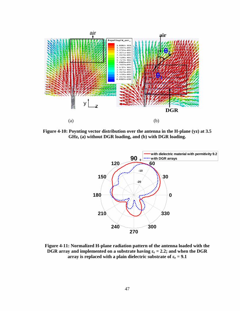
47
DGR
airair
yz
θ1
θ2
(a) (b)
Figure 4-10: Poynting vector distribution over the antenna in the H-plane (yz) at 3.5
GHz, (a) without DGR loading, and (b) with DGR loading.
Figure 4-11: Normalized H-plane radiation pattern of the antenna loaded with the
DGR array and implemented on a substrate having εr = 2.2; and when the DGR
array is replaced with a plain dielectric substrate of εr = 9.1
-20
-10
0
30
210
60
240
90
270
120
300
150
330
180 0
with dielectric material with permitivity 9.2
with DGR arrays
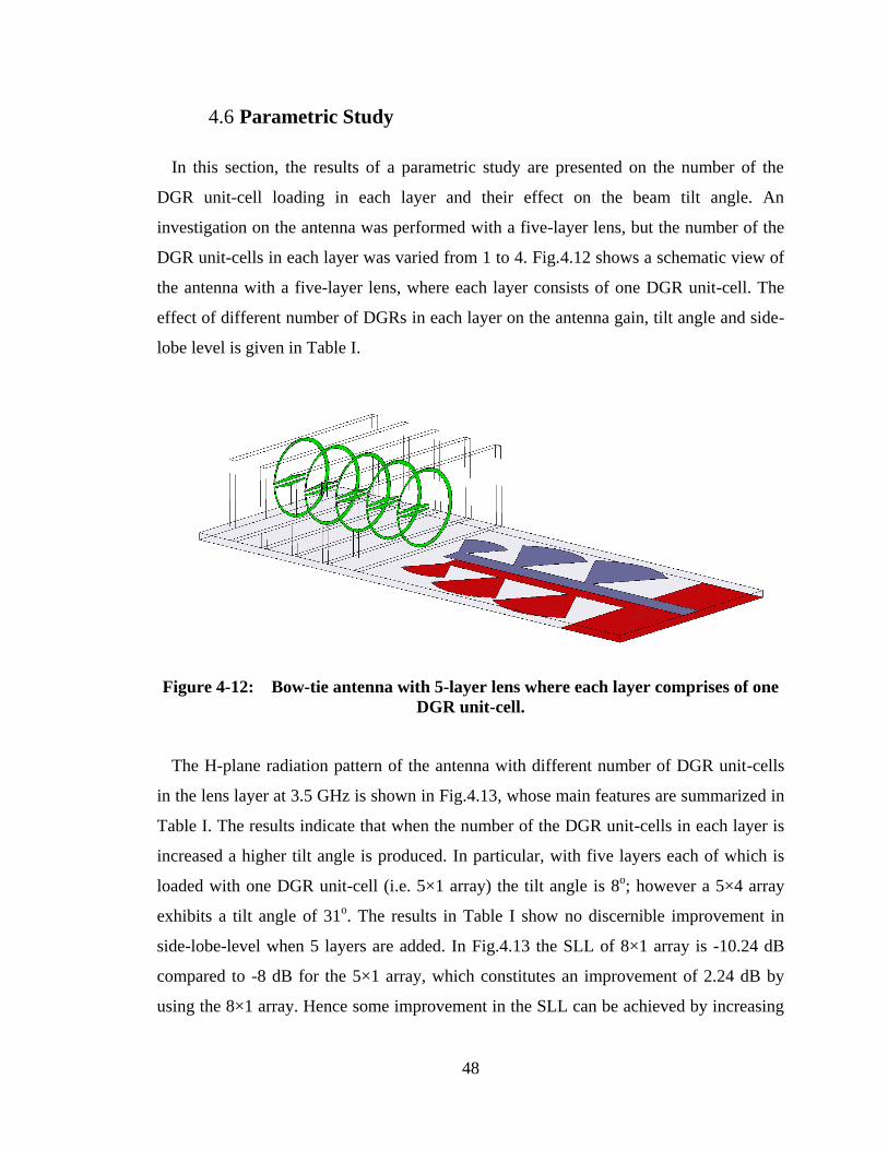
48
4.6 Parametric Study
In this section, the results of a parametric study are presented on the number of the
DGR unit-cell loading in each layer and their effect on the beam tilt angle. An
investigation on the antenna was performed with a five-layer lens, but the number of the
DGR unit-cells in each layer was varied from 1 to 4. Fig.4.12 shows a schematic view of
the antenna with a five-layer lens, where each layer consists of one DGR unit-cell. The
effect of different number of DGRs in each layer on the antenna gain, tilt angle and side-
lobe level is given in Table I.
Figure 4-12: Bow-tie antenna with 5-layer lens where each layer comprises of one
DGR unit-cell.
The H-plane radiation pattern of the antenna with different number of DGR unit-cells
in the lens layer at 3.5 GHz is shown in Fig.4.13, whose main features are summarized in
Table I. The results indicate that when the number of the DGR unit-cells in each layer is
increased a higher tilt angle is produced. In particular, with five layers each of which is
loaded with one DGR unit-cell (i.e. 5×1 array) the tilt angle is 8o; however a 5×4 array
exhibits a tilt angle of 31o. The results in Table I show no discernible improvement in
side-lobe-level when 5 layers are added. In Fig.4.13 the SLL of 8×1 array is -10.24 dB
compared to -8 dB for the 5×1 array, which constitutes an improvement of 2.24 dB by
using the 8×1 array. Hence some improvement in the SLL can be achieved by increasing
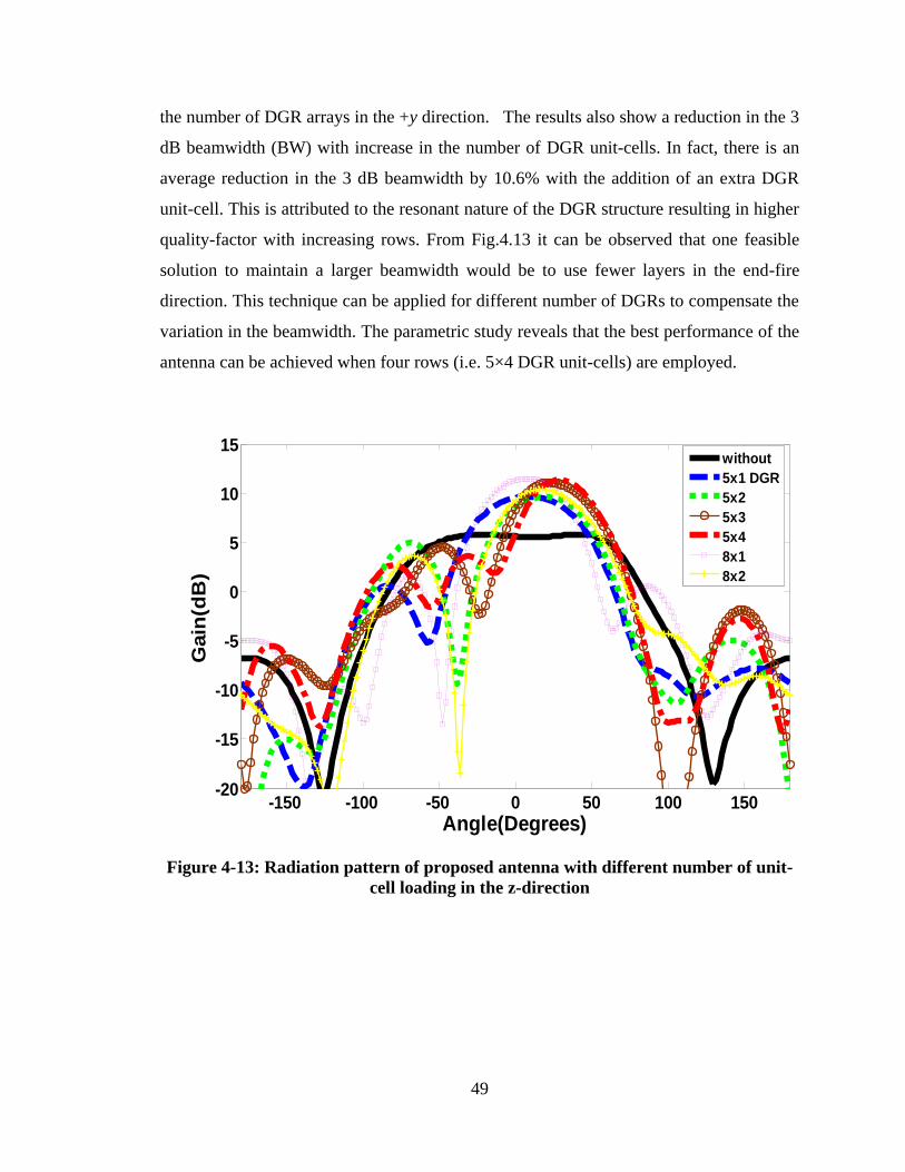
49
the number of DGR arrays in the +y direction. The results also show a reduction in the 3
dB beamwidth (BW) with increase in the number of DGR unit-cells. In fact, there is an
average reduction in the 3 dB beamwidth by 10.6% with the addition of an extra DGR
unit-cell. This is attributed to the resonant nature of the DGR structure resulting in higher
quality-factor with increasing rows. From Fig.4.13 it can be observed that one feasible
solution to maintain a larger beamwidth would be to use fewer layers in the end-fire
direction. This technique can be applied for different number of DGRs to compensate the
variation in the beamwidth. The parametric study reveals that the best performance of the
antenna can be achieved when four rows (i.e. 5×4 DGR unit-cells) are employed.
Figure 4-13: Radiation pattern of proposed antenna with different number of unit-
cell loading in the z-direction
-150 -100 -50 0 50 100 150-20
-15
-10
-5
0
5
10
15
Angle(Degrees)
Gain
(dB
)
without
5x1 DGR
5x2
5x3
5x4
8x1
8x2
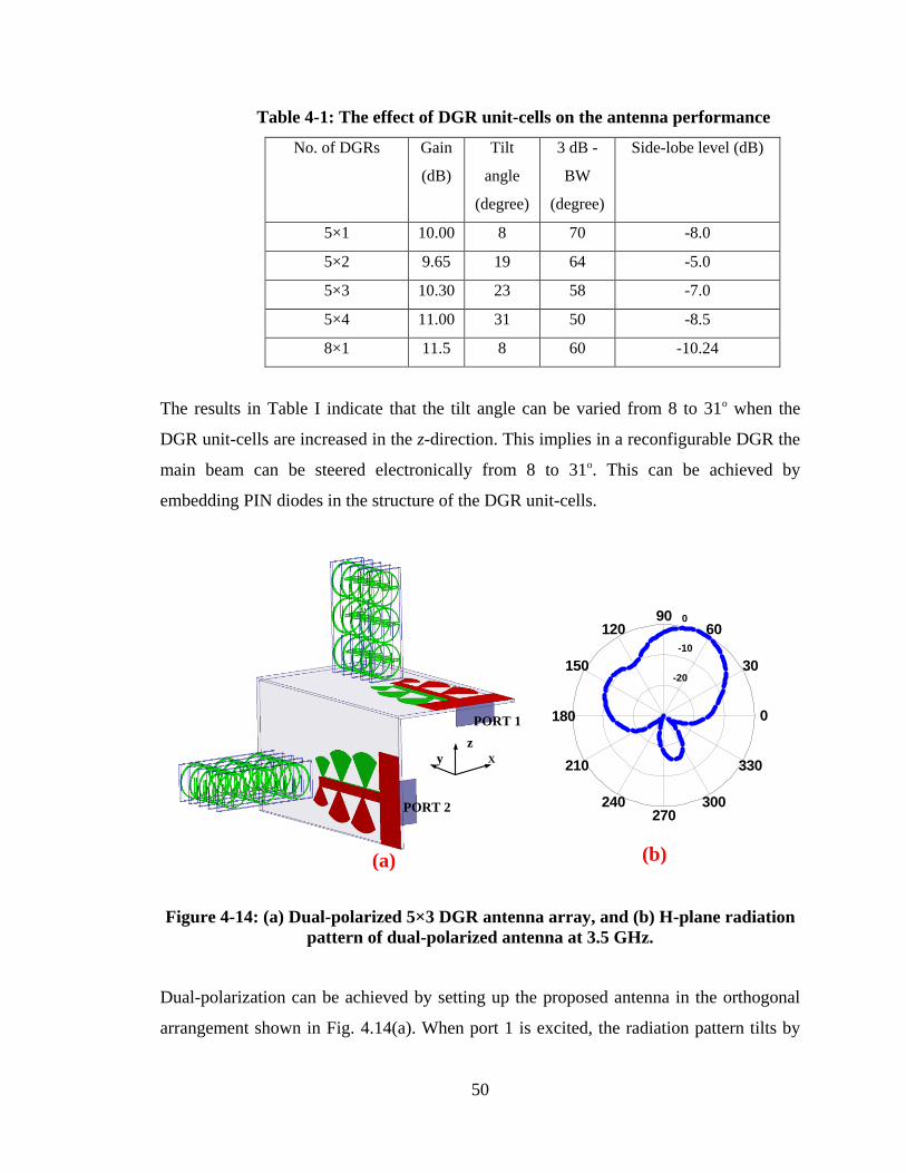
50
Table 4-1: The effect of DGR unit-cells on the antenna performance
No. of DGRs Gain
(dB)
Tilt
angle
(degree)
3 dB -
BW
(degree)
Side-lobe level (dB)
5×1 10.00 8 70 -8.0
5×2 9.65 19 64 -5.0
5×3 10.30 23 58 -7.0
5×4 11.00 31 50 -8.5
8×1 11.5 8 60 -10.24
The results in Table I indicate that the tilt angle can be varied from 8 to 31o when the
DGR unit-cells are increased in the z-direction. This implies in a reconfigurable DGR the
main beam can be steered electronically from 8 to 31o. This can be achieved by
embedding PIN diodes in the structure of the DGR unit-cells.
Xy
PORT 1
PORT 2
z
-20
-10
0
30
210
60
240
90
270
120
300
150
330
180 0
(a) (b)
Figure 4-14: (a) Dual-polarized 5×3 DGR antenna array, and (b) H-plane radiation
pattern of dual-polarized antenna at 3.5 GHz.
Dual-polarization can be achieved by setting up the proposed antenna in the orthogonal
arrangement shown in Fig. 4.14(a). When port 1 is excited, the radiation pattern tilts by
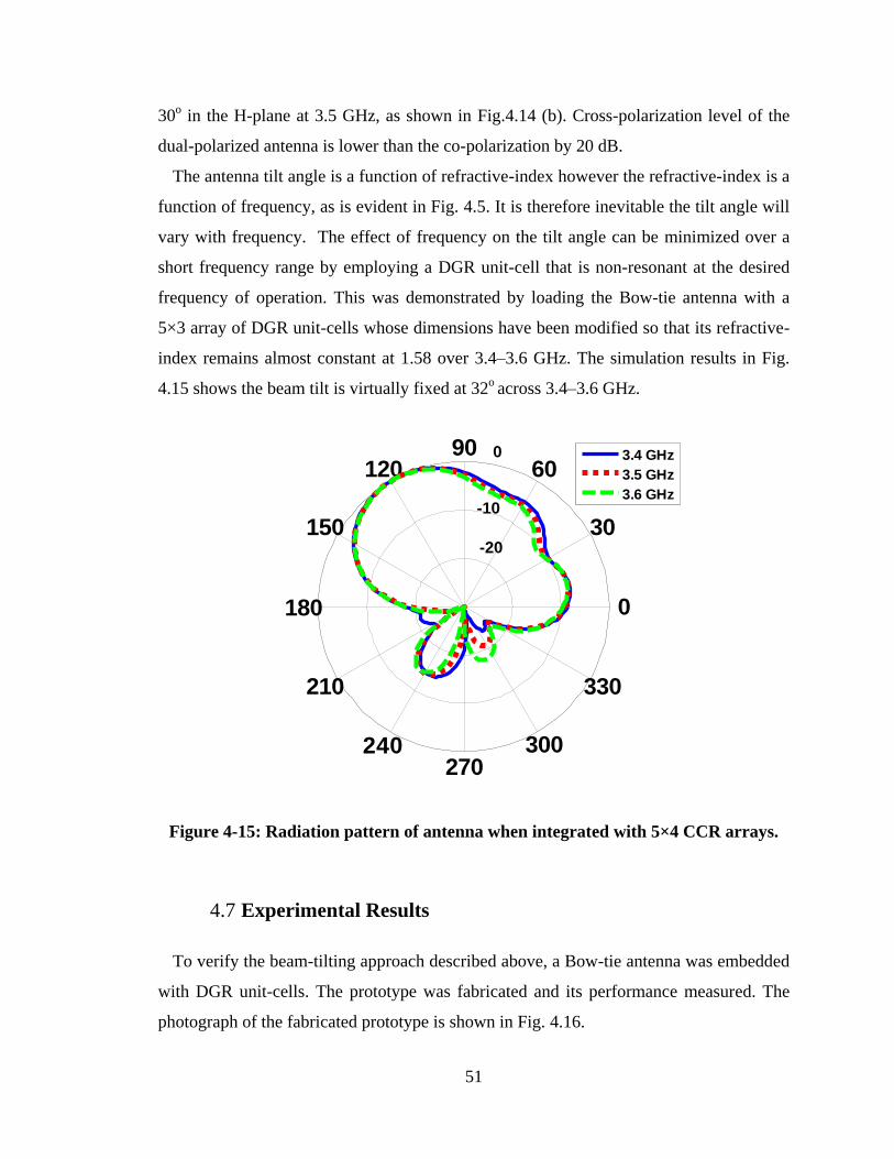
51
30o in the H-plane at 3.5 GHz, as shown in Fig.4.14 (b). Cross-polarization level of the
dual-polarized antenna is lower than the co-polarization by 20 dB.
The antenna tilt angle is a function of refractive-index however the refractive-index is a
function of frequency, as is evident in Fig. 4.5. It is therefore inevitable the tilt angle will
vary with frequency. The effect of frequency on the tilt angle can be minimized over a
short frequency range by employing a DGR unit-cell that is non-resonant at the desired
frequency of operation. This was demonstrated by loading the Bow-tie antenna with a
5×3 array of DGR unit-cells whose dimensions have been modified so that its refractive-
index remains almost constant at 1.58 over 3.4–3.6 GHz. The simulation results in Fig.
4.15 shows the beam tilt is virtually fixed at 32o across 3.4–3.6 GHz.
-20
-10
0
30
210
60
240
90
270
120
300
150
330
180 0
3.4 GHz
3.5 GHz
3.6 GHz
Figure 4-15: Radiation pattern of antenna when integrated with 5×4 CCR arrays.
4.7 Experimental Results
To verify the beam-tilting approach described above, a Bow-tie antenna was embedded
with DGR unit-cells. The prototype was fabricated and its performance measured. The
photograph of the fabricated prototype is shown in Fig. 4.16.
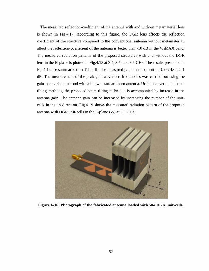
52
The measured reflection-coefficient of the antenna with and without metamaterial lens
is shown in Fig.4.17. According to this figure, the DGR lens affects the reflection
coefficient of the structure compared to the conventional antenna without metamaterial,
albeit the reflection-coefficient of the antenna is better than -10 dB in the WiMAX band.
The measured radiation patterns of the proposed structures with and without the DGR
lens in the H-plane is plotted in Fig.4.18 at 3.4, 3.5, and 3.6 GHz. The results presented in
Fig.4.18 are summarized in Table II. The measured gain enhancement at 3.5 GHz is 5.1
dB. The measurement of the peak gain at various frequencies was carried out using the
gain-comparison method with a known standard horn antenna. Unlike conventional beam
tilting methods, the proposed beam tilting technique is accompanied by increase in the
antenna gain. The antenna gain can be increased by increasing the number of the unit-
cells in the +y direction. Fig.4.19 shows the measured radiation pattern of the proposed
antenna with DGR unit-cells in the E-plane (xy) at 3.5 GHz.
Figure 4-16: Photograph of the fabricated antenna loaded with 5×4 DGR unit-cells.
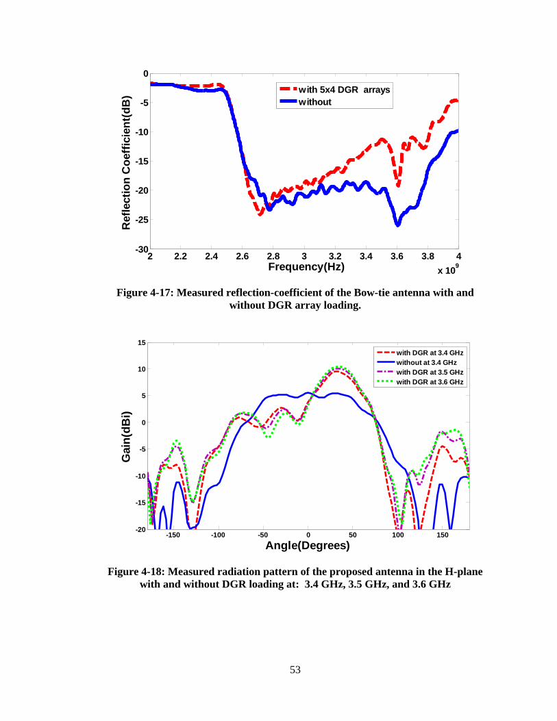
53
Figure 4-17: Measured reflection-coefficient of the Bow-tie antenna with and
without DGR array loading.
Figure 4-18: Measured radiation pattern of the proposed antenna in the H-plane
with and without DGR loading at: 3.4 GHz, 3.5 GHz, and 3.6 GHz
2 2.2 2.4 2.6 2.8 3 3.2 3.4 3.6 3.8 4
x 109
-30
-25
-20
-15
-10
-5
0
Frequency(Hz)
Refl
ecti
on
Co
eff
icie
nt(
dB
)
with 5x4 DGR arrays
without
-150 -100 -50 0 50 100 150-20
-15
-10
-5
0
5
10
15
Angle(Degrees)
Gain
(dB
i)
with DGR at 3.4 GHz
without at 3.4 GHz
with DGR at 3.5 GHz
with DGR at 3.6 GHz
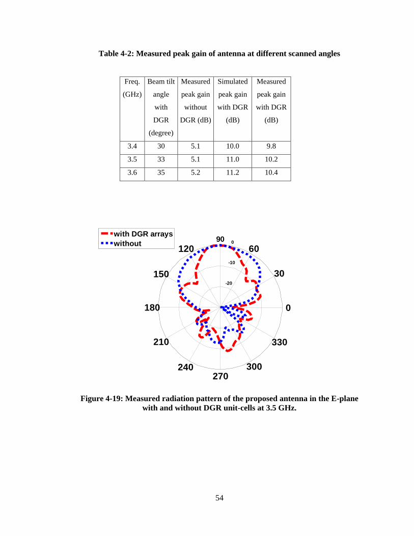
54
Table 4-2: Measured peak gain of antenna at different scanned angles
Freq.
(GHz)
Beam tilt
angle
with
DGR
(degree)
Measured
peak gain
without
DGR (dB)
Simulated
peak gain
with DGR
(dB)
Measured
peak gain
with DGR
(dB)
3.4 30 5.1 10.0 9.8
3.5 33 5.1 11.0 10.2
3.6 35 5.2 11.2 10.4
Figure 4-19: Measured radiation pattern of the proposed antenna in the E-plane
with and without DGR unit-cells at 3.5 GHz.
-20
-10
0
30
210
60
240
90
270
120
300
150
330
180 0
with DGR arrays
without
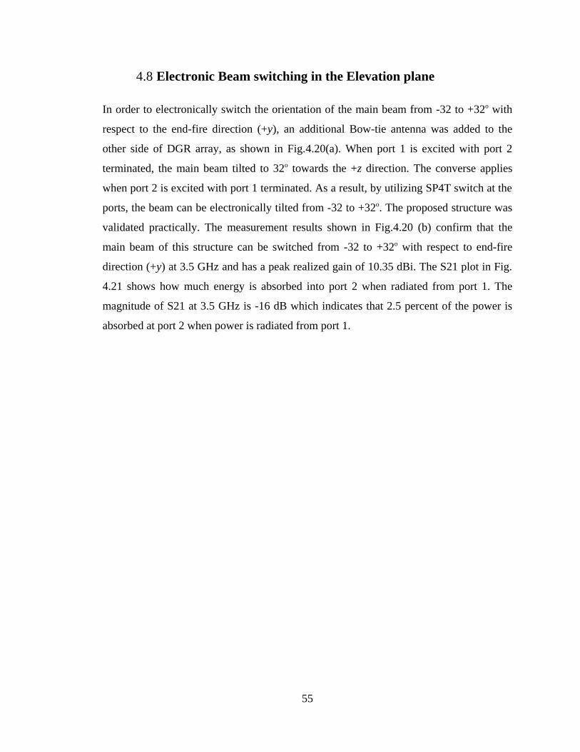
55
4.8 Electronic Beam switching in the Elevation plane
In order to electronically switch the orientation of the main beam from -32 to +32o with
respect to the end-fire direction (+y), an additional Bow-tie antenna was added to the
other side of DGR array, as shown in Fig.4.20(a). When port 1 is excited with port 2
terminated, the main beam tilted to 32o towards the +z direction. The converse applies
when port 2 is excited with port 1 terminated. As a result, by utilizing SP4T switch at the
ports, the beam can be electronically tilted from -32 to +32o. The proposed structure was
validated practically. The measurement results shown in Fig.4.20 (b) confirm that the
main beam of this structure can be switched from -32 to +32o with respect to end-fire
direction (+y) at 3.5 GHz and has a peak realized gain of 10.35 dBi. The S21 plot in Fig.
4.21 shows how much energy is absorbed into port 2 when radiated from port 1. The
magnitude of S21 at 3.5 GHz is -16 dB which indicates that 2.5 percent of the power is
absorbed at port 2 when power is radiated from port 1.
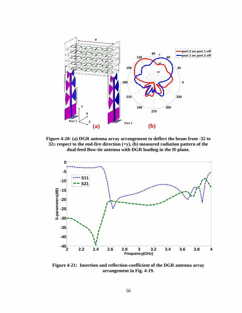
56
X
Y
Z Port 2Port 1
d
-20
-10
0
30
210
60
240
90
270
120
300
150
330
180 0
port 2 on port 1 off
port 1 on port 2 off
(a) (b)
Figure 4-20: (a) DGR antenna array arrangement to deflect the beam from -32 to
32o respect to the end-fire direction (+y), (b) measured radiation pattern of the
dual-feed Bow-tie antenna with DGR loading in the H-plane.
Figure 4-21: Insertion and reflection-coefficient of the DGR antenna array
arrangement in Fig. 4-19.
2 2.2 2.4 2.6 2.8 3 3.2 3.4 3.6 3.8 4-45
-40
-35
-30
-25
-20
-15
-10
-5
0
Frequency(GHz)
S-p
ara
mete
rs(d
B)
S11
S21
57
4.1 Conclusion
A novel beam-tilting technique has been described for planar end-fire antennas like the
Bow-tie. The technique uses an artificial composite structure with a high dielectric
constant. Proof-of-concept is demonstrated at the WiMAX band (3.4–3.6 GHz). The
proposed structure consists of three Bow-tie radiators connected symmetrically to a
microstrip-line, and included in the vicinity of the radiators in the H-plane is a 5×4 array
of DGR unit-cells that act as high refractive-index medium. The measured results show
that the proposed lens tilts the antenna main beam by 35o in the H-plane at 3.6 GHz. The
maximum measured gain of the beam-tilting antenna is 10.4 dB at 3.6 GHz compared to
5.2 dB without the lens. Unlike conventional tilting methods, the proposed technique is
accompanied by a gain enhancement. The magnitude of the reflection-coefficient is
maintained better than -10 dB in the WiMAX band when the beam is tilted. The validity
of the proposed technique for electronic beam switching networks was verified. A
prototype of a double Bow-tie antenna arrangement using a 5×4 DGR array was
fabricated and its performance measured. It was shown the main beam of the prototype is
electronically switchable from -32 to +32o at 3.5 GHz. The proposed DGR Bow-tie
antenna presents a viable candidate for future cellular or WiMAX applications
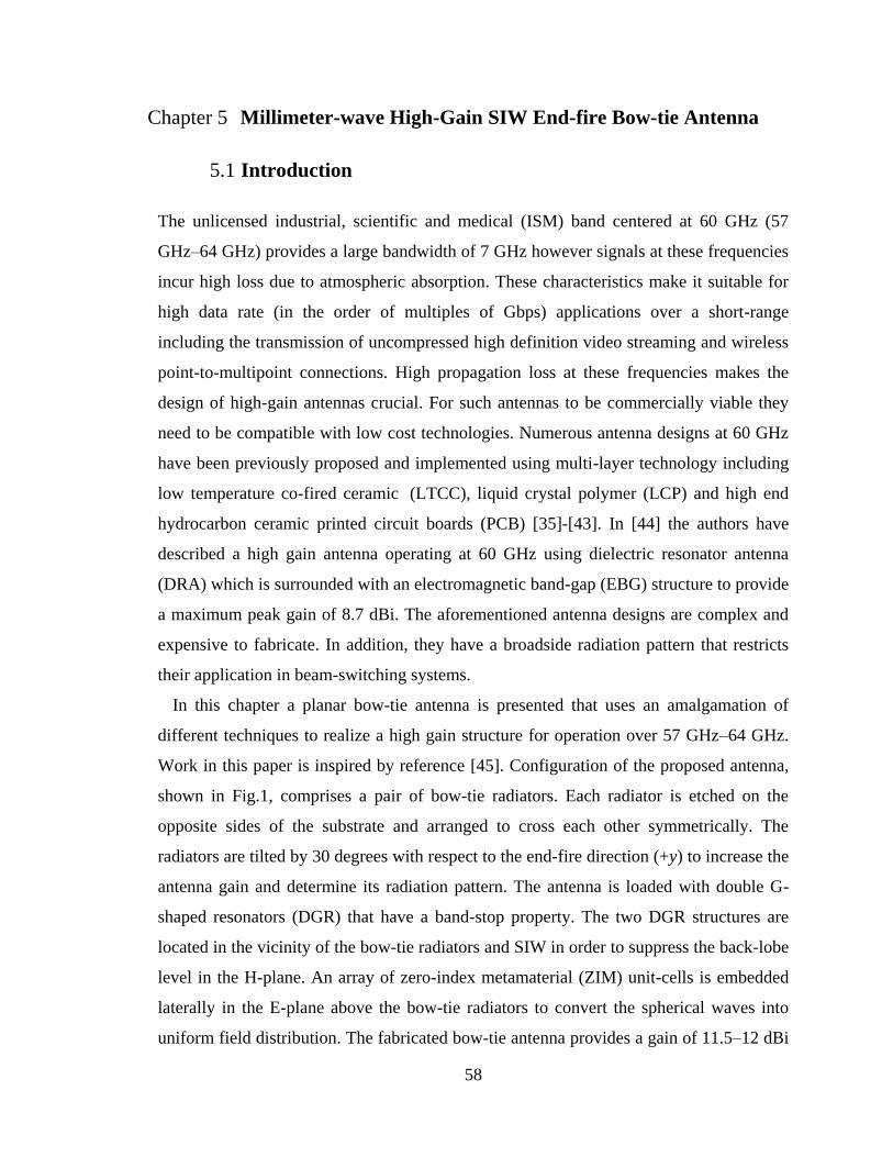
58
Chapter 5 Millimeter-wave High-Gain SIW End-fire Bow-tie Antenna
5.1 Introduction
The unlicensed industrial, scientific and medical (ISM) band centered at 60 GHz (57
GHz–64 GHz) provides a large bandwidth of 7 GHz however signals at these frequencies
incur high loss due to atmospheric absorption. These characteristics make it suitable for
high data rate (in the order of multiples of Gbps) applications over a short-range
including the transmission of uncompressed high definition video streaming and wireless
point-to-multipoint connections. High propagation loss at these frequencies makes the
design of high-gain antennas crucial. For such antennas to be commercially viable they
need to be compatible with low cost technologies. Numerous antenna designs at 60 GHz
have been previously proposed and implemented using multi-layer technology including
low temperature co-fired ceramic (LTCC), liquid crystal polymer (LCP) and high end
hydrocarbon ceramic printed circuit boards (PCB) [35]-[43]. In [44] the authors have
described a high gain antenna operating at 60 GHz using dielectric resonator antenna
(DRA) which is surrounded with an electromagnetic band-gap (EBG) structure to provide
a maximum peak gain of 8.7 dBi. The aforementioned antenna designs are complex and
expensive to fabricate. In addition, they have a broadside radiation pattern that restricts
their application in beam-switching systems.
In this chapter a planar bow-tie antenna is presented that uses an amalgamation of
different techniques to realize a high gain structure for operation over 57 GHz–64 GHz.
Work in this paper is inspired by reference [45]. Configuration of the proposed antenna,
shown in Fig.1, comprises a pair of bow-tie radiators. Each radiator is etched on the
opposite sides of the substrate and arranged to cross each other symmetrically. The
radiators are tilted by 30 degrees with respect to the end-fire direction (+y) to increase the
antenna gain and determine its radiation pattern. The antenna is loaded with double G-
shaped resonators (DGR) that have a band-stop property. The two DGR structures are
located in the vicinity of the bow-tie radiators and SIW in order to suppress the back-lobe
level in the H-plane. An array of zero-index metamaterial (ZIM) unit-cells is embedded
laterally in the E-plane above the bow-tie radiators to convert the spherical waves into
uniform field distribution. The fabricated bow-tie antenna provides a gain of 11.5–12 dBi
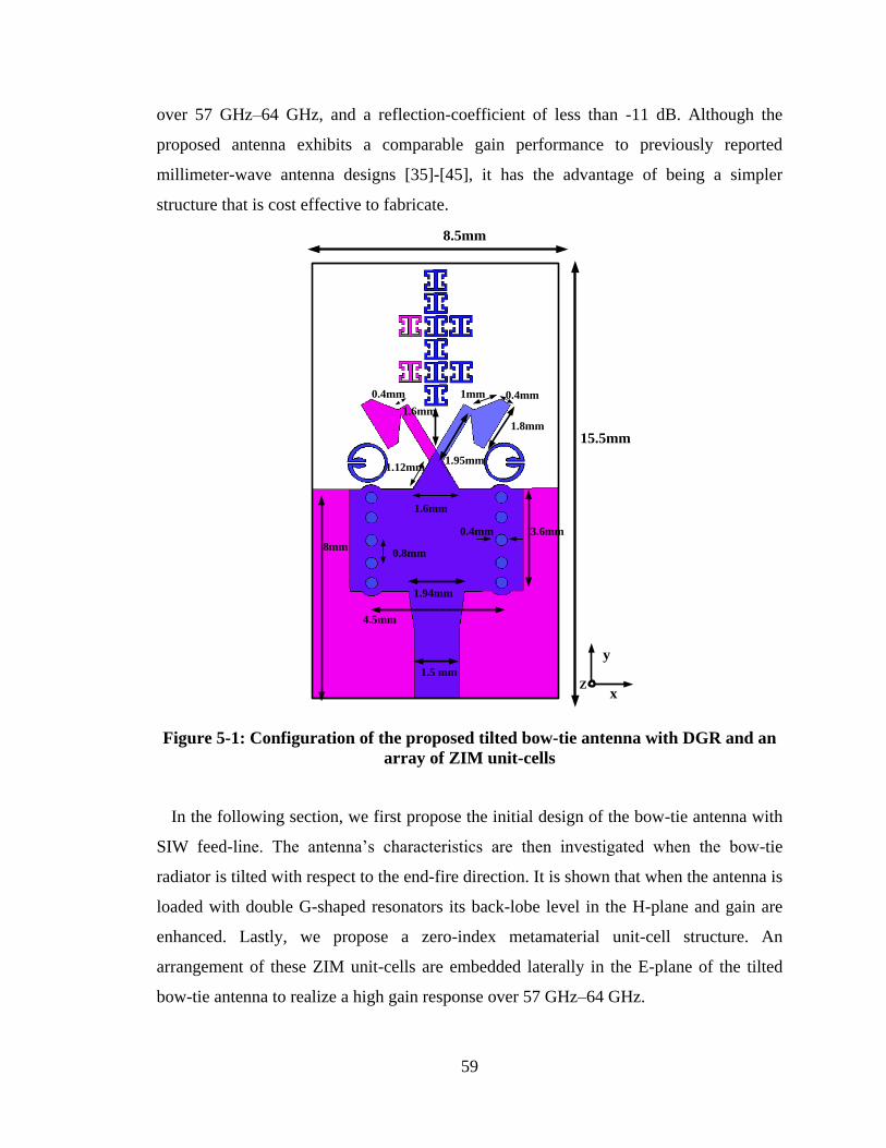
59
over 57 GHz–64 GHz, and a reflection-coefficient of less than -11 dB. Although the
proposed antenna exhibits a comparable gain performance to previously reported
millimeter-wave antenna designs [35]-[45], it has the advantage of being a simpler
structure that is cost effective to fabricate.
Figure 5-1: Configuration of the proposed tilted bow-tie antenna with DGR and an
array of ZIM unit-cells
In the following section, we first propose the initial design of the bow-tie antenna with
SIW feed-line. The antenna‟s characteristics are then investigated when the bow-tie
radiator is tilted with respect to the end-fire direction. It is shown that when the antenna is
loaded with double G-shaped resonators its back-lobe level in the H-plane and gain are
enhanced. Lastly, we propose a zero-index metamaterial unit-cell structure. An
arrangement of these ZIM unit-cells are embedded laterally in the E-plane of the tilted
bow-tie antenna to realize a high gain response over 57 GHz–64 GHz.
15.5mm
0.4mm
1.8mm
1.6mm
1mm
3.6mm0.4mm
0.8mm
1.6mm
1.94mm
x
y
8.5mm
4.5mm
8mm
1.95mm
0.4mm
1.5 mm
1.12mm
Z
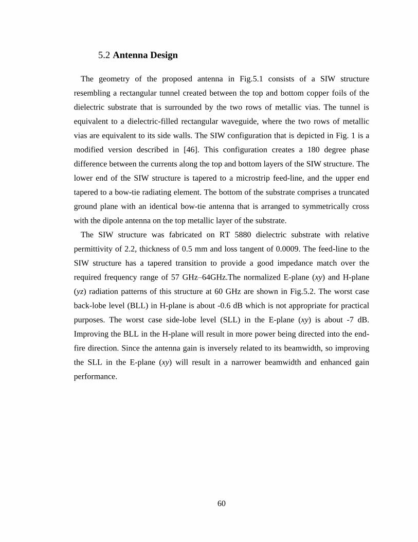
60
5.2 Antenna Design
The geometry of the proposed antenna in Fig.5.1 consists of a SIW structure
resembling a rectangular tunnel created between the top and bottom copper foils of the
dielectric substrate that is surrounded by the two rows of metallic vias. The tunnel is
equivalent to a dielectric-filled rectangular waveguide, where the two rows of metallic
vias are equivalent to its side walls. The SIW configuration that is depicted in Fig. 1 is a
modified version described in [46]. This configuration creates a 180 degree phase
difference between the currents along the top and bottom layers of the SIW structure. The
lower end of the SIW structure is tapered to a microstrip feed-line, and the upper end
tapered to a bow-tie radiating element. The bottom of the substrate comprises a truncated
ground plane with an identical bow-tie antenna that is arranged to symmetrically cross
with the dipole antenna on the top metallic layer of the substrate.
The SIW structure was fabricated on RT 5880 dielectric substrate with relative
permittivity of 2.2, thickness of 0.5 mm and loss tangent of 0.0009. The feed-line to the
SIW structure has a tapered transition to provide a good impedance match over the
required frequency range of 57 GHz–64GHz.The normalized E-plane (xy) and H-plane
(yz) radiation patterns of this structure at 60 GHz are shown in Fig.5.2. The worst case
back-lobe level (BLL) in H-plane is about -0.6 dB which is not appropriate for practical
purposes. The worst case side-lobe level (SLL) in the E-plane (xy) is about -7 dB.
Improving the BLL in the H-plane will result in more power being directed into the end-
fire direction. Since the antenna gain is inversely related to its beamwidth, so improving
the SLL in the E-plane (xy) will result in a narrower beamwidth and enhanced gain
performance.
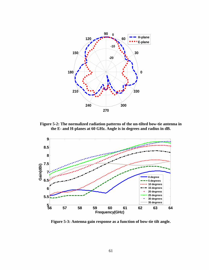
61
Figure 5-2: The normalized radiation patterns of the un-tilted bow-tie antenna in
the E- and H-planes at 60 GHz. Angle is in degrees and radius in dB.
Figure 5-3: Antenna gain response as a function of bow-tie tilt angle.
-20
-10
0
30
210
60
240
90
270
120
300
150
330
180 0
H-plane
E-plane
56 57 58 59 60 61 62 63 645
5.5
6
6.5
7
7.5
8
8.5
9
Frequency(GHz)
Gain
(dB
i)
0 degree
5 degrees
10 degrees
15 degrees
20 degress
25 degrees
30 degrees
35 degrees
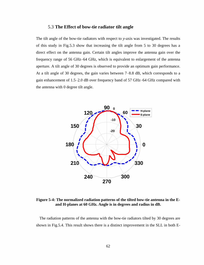
62
5.3 The Effect of bow-tie radiator tilt angle
The tilt angle of the bow-tie radiators with respect to y-axis was investigated. The results
of this study in Fig.5.3 show that increasing the tilt angle from 5 to 30 degrees has a
direct effect on the antenna gain. Certain tilt angles improve the antenna gain over the
frequency range of 56 GHz–64 GHz, which is equivalent to enlargement of the antenna
aperture. A tilt angle of 30 degrees is observed to provide an optimum gain performance.
At a tilt angle of 30 degrees, the gain varies between 7–8.8 dB, which corresponds to a
gain enhancement of 1.5–2.0 dB over frequency band of 57 GHz–64 GHz compared with
the antenna with 0 degree tilt angle.
-20
-10
0
30
210
60
240
90
270
120
300
150
330
180 0
H-plane
E-plane
Figure 5-4: The normalized radiation patterns of the tilted bow-tie antenna in the E-
and H-planes at 60 GHz. Angle is in degrees and radius in dB.
The radiation patterns of the antenna with the bow-tie radiators tilted by 30 degrees are
shown in Fig.5.4. This result shows there is a distinct improvement in the SLL in both E-
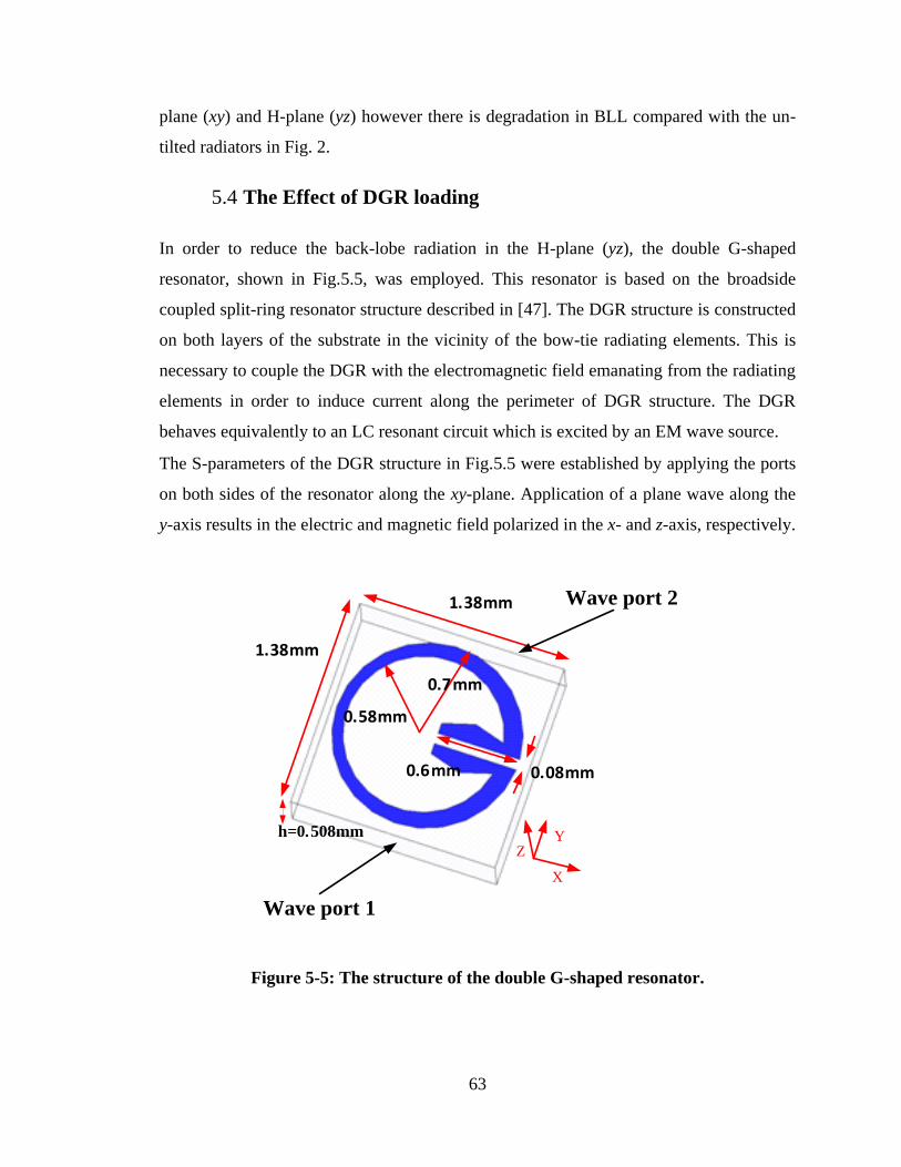
63
plane (xy) and H-plane (yz) however there is degradation in BLL compared with the un-
tilted radiators in Fig. 2.
5.4 The Effect of DGR loading
In order to reduce the back-lobe radiation in the H-plane (yz), the double G-shaped
resonator, shown in Fig.5.5, was employed. This resonator is based on the broadside
coupled split-ring resonator structure described in [47]. The DGR structure is constructed
on both layers of the substrate in the vicinity of the bow-tie radiating elements. This is
necessary to couple the DGR with the electromagnetic field emanating from the radiating
elements in order to induce current along the perimeter of DGR structure. The DGR
behaves equivalently to an LC resonant circuit which is excited by an EM wave source.
The S-parameters of the DGR structure in Fig.5.5 were established by applying the ports
on both sides of the resonator along the xy-plane. Application of a plane wave along the
y-axis results in the electric and magnetic field polarized in the x- and z-axis, respectively.
0.58mm
0.7mm
0.6mm 0.08mm
1.38mm
1.38mm
h=0.508mm
X
YZ
Wave port 1
Wave port 2
Figure 5-5: The structure of the double G-shaped resonator.
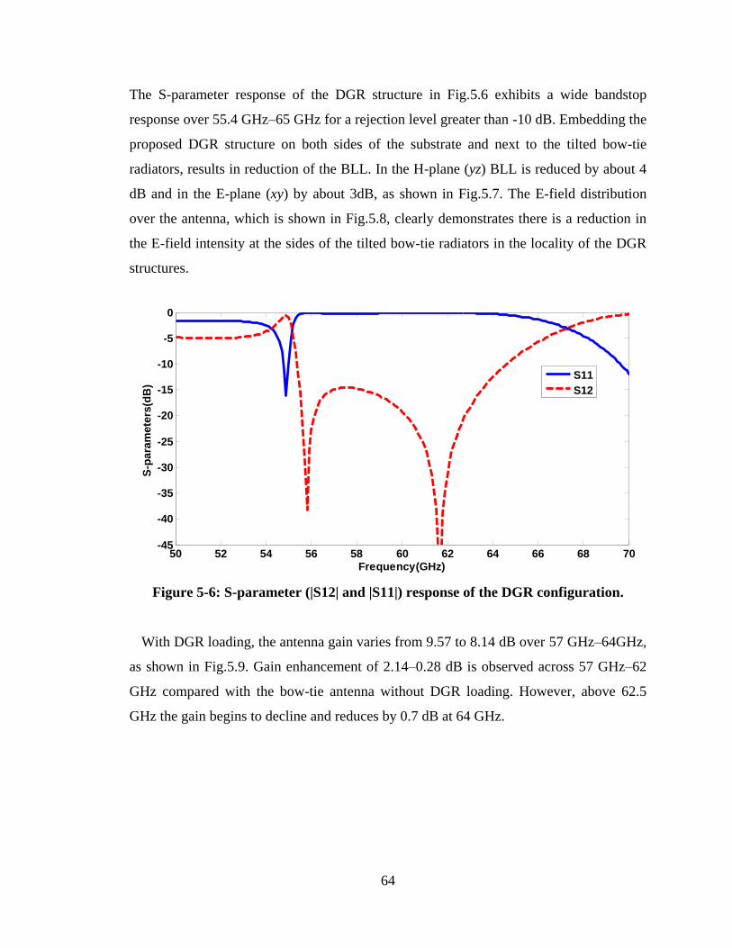
64
The S-parameter response of the DGR structure in Fig.5.6 exhibits a wide bandstop
response over 55.4 GHz–65 GHz for a rejection level greater than -10 dB. Embedding the
proposed DGR structure on both sides of the substrate and next to the tilted bow-tie
radiators, results in reduction of the BLL. In the H-plane (yz) BLL is reduced by about 4
dB and in the E-plane (xy) by about 3dB, as shown in Fig.5.7. The E-field distribution
over the antenna, which is shown in Fig.5.8, clearly demonstrates there is a reduction in
the E-field intensity at the sides of the tilted bow-tie radiators in the locality of the DGR
structures.
Figure 5-6: S-parameter (|S12| and |S11|) response of the DGR configuration.
With DGR loading, the antenna gain varies from 9.57 to 8.14 dB over 57 GHz–64GHz,
as shown in Fig.5.9. Gain enhancement of 2.14–0.28 dB is observed across 57 GHz–62
GHz compared with the bow-tie antenna without DGR loading. However, above 62.5
GHz the gain begins to decline and reduces by 0.7 dB at 64 GHz.
50 52 54 56 58 60 62 64 66 68 70-45
-40
-35
-30
-25
-20
-15
-10
-5
0
Frequency(GHz)
S-p
ara
mete
rs(d
B)
S11
S12
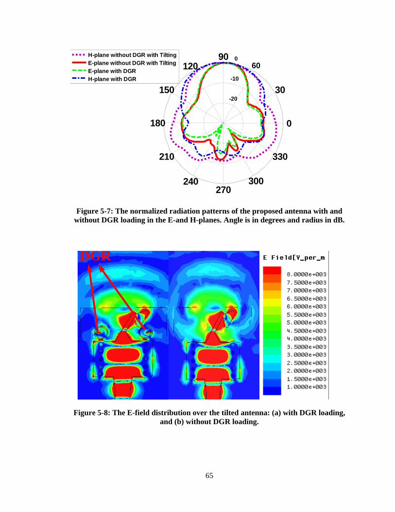
65
-20
-10
0
30
210
60
240
90
270
120
300
150
330
180 0
H-plane without DGR with Tilting
E-plane without DGR with Tilting
E-plane with DGR
H-plane with DGR
Figure 5-7: The normalized radiation patterns of the proposed antenna with and
without DGR loading in the E-and H-planes. Angle is in degrees and radius in dB.
DGR
Figure 5-8: The E-field distribution over the tilted antenna: (a) with DGR loading,
and (b) without DGR loading.
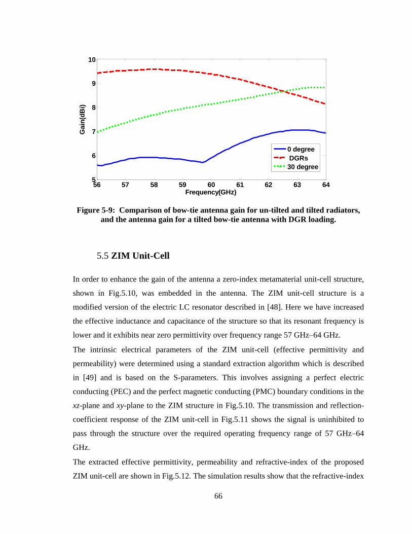
66
Figure 5-9: Comparison of bow-tie antenna gain for un-tilted and tilted radiators,
and the antenna gain for a tilted bow-tie antenna with DGR loading.
5.5 ZIM Unit-Cell
In order to enhance the gain of the antenna a zero-index metamaterial unit-cell structure,
shown in Fig.5.10, was embedded in the antenna. The ZIM unit-cell structure is a
modified version of the electric LC resonator described in [48]. Here we have increased
the effective inductance and capacitance of the structure so that its resonant frequency is
lower and it exhibits near zero permittivity over frequency range 57 GHz–64 GHz.
The intrinsic electrical parameters of the ZIM unit-cell (effective permittivity and
permeability) were determined using a standard extraction algorithm which is described
in [49] and is based on the S-parameters. This involves assigning a perfect electric
conducting (PEC) and the perfect magnetic conducting (PMC) boundary conditions in the
xz-plane and xy-plane to the ZIM structure in Fig.5.10. The transmission and reflection-
coefficient response of the ZIM unit-cell in Fig.5.11 shows the signal is uninhibited to
pass through the structure over the required operating frequency range of 57 GHz–64
GHz.
The extracted effective permittivity, permeability and refractive-index of the proposed
ZIM unit-cell are shown in Fig.5.12. The simulation results show that the refractive-index
56 57 58 59 60 61 62 63 645
6
7
8
9
10
Frequency(GHz)
Gain
(dB
i)
0 degree
DGRs
30 degree
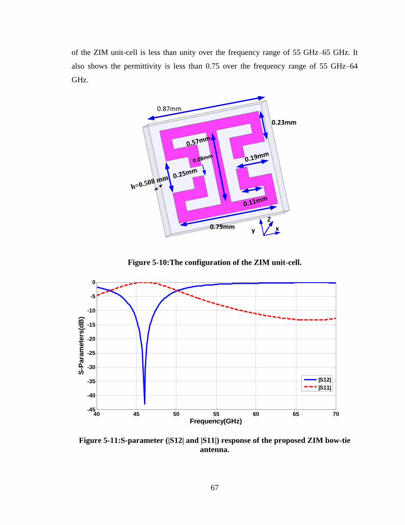
67
of the ZIM unit-cell is less than unity over the frequency range of 55 GHz–65 GHz. It
also shows the permittivity is less than 0.75 over the frequency range of 55 GHz–64
GHz.
0.79mm
0.23mm
0.87mm
0.19mm
0.11mm
0.25mm
xy
0.57mm
0.08mm
Z
h=0.508 mm
Figure 5-10:The configuration of the ZIM unit-cell.
Figure 5-11:S-parameter (|S12| and |S11|) response of the proposed ZIM bow-tie
antenna.
40 45 50 55 60 65 70-45
-40
-35
-30
-25
-20
-15
-10
-5
0
Frequency(GHz)
S-P
ara
mete
rs(d
B)
|S12|
|S11|
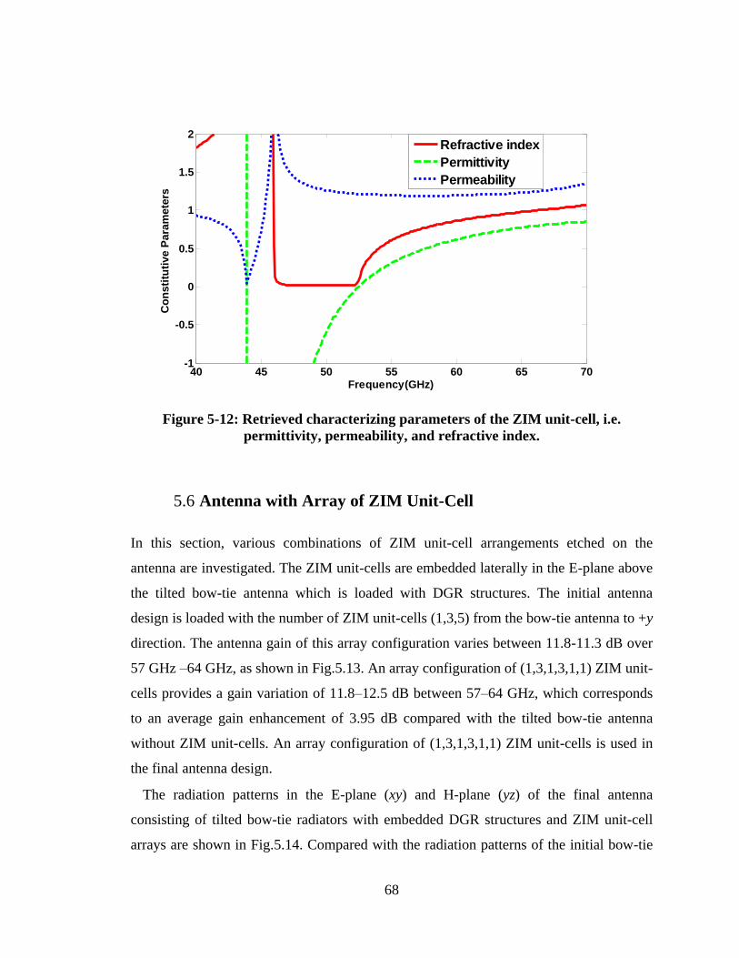
68
Figure 5-12: Retrieved characterizing parameters of the ZIM unit-cell, i.e.
permittivity, permeability, and refractive index.
5.6 Antenna with Array of ZIM Unit-Cell
In this section, various combinations of ZIM unit-cell arrangements etched on the
antenna are investigated. The ZIM unit-cells are embedded laterally in the E-plane above
the tilted bow-tie antenna which is loaded with DGR structures. The initial antenna
design is loaded with the number of ZIM unit-cells (1,3,5) from the bow-tie antenna to +y
direction. The antenna gain of this array configuration varies between 11.8-11.3 dB over
57 GHz –64 GHz, as shown in Fig.5.13. An array configuration of (1,3,1,3,1,1) ZIM unit-
cells provides a gain variation of 11.8–12.5 dB between 57–64 GHz, which corresponds
to an average gain enhancement of 3.95 dB compared with the tilted bow-tie antenna
without ZIM unit-cells. An array configuration of (1,3,1,3,1,1) ZIM unit-cells is used in
the final antenna design.
The radiation patterns in the E-plane (xy) and H-plane (yz) of the final antenna
consisting of tilted bow-tie radiators with embedded DGR structures and ZIM unit-cell
arrays are shown in Fig.5.14. Compared with the radiation patterns of the initial bow-tie
40 45 50 55 60 65 70-1
-0.5
0
0.5
1
1.5
2
Frequency(GHz)
Co
ns
titu
tiv
e P
ara
mete
rs
Refractive index
Permittivity
Permeability
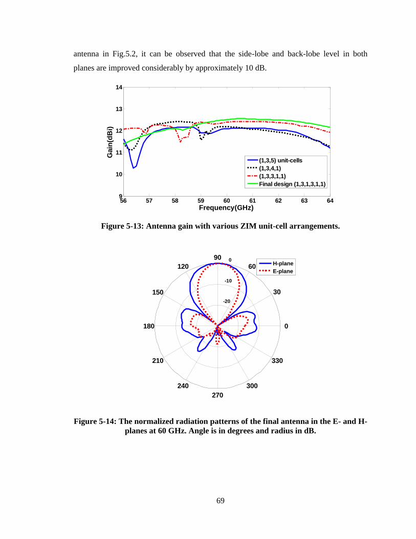
69
antenna in Fig.5.2, it can be observed that the side-lobe and back-lobe level in both
planes are improved considerably by approximately 10 dB.
Figure 5-13: Antenna gain with various ZIM unit-cell arrangements.
Figure 5-14: The normalized radiation patterns of the final antenna in the E- and H-
planes at 60 GHz. Angle is in degrees and radius in dB.
56 57 58 59 60 61 62 63 649
10
11
12
13
14
Frequency(GHz)
Gain
(dB
i)
(1,3,5) unit-cells
(1,3,4,1)
(1,3,3,1,1)
Final design (1,3,1,3,1,1)
-20
-10
0
30
210
60
240
90
270
120
300
150
330
180 0
H-plane
E-plane
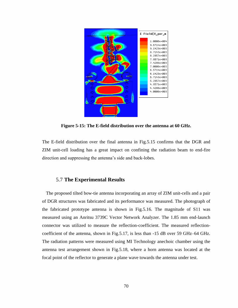
70
Figure 5-15: The E-field distribution over the antenna at 60 GHz.
The E-field distribution over the final antenna in Fig.5.15 confirms that the DGR and
ZIM unit-cell loading has a great impact on confining the radiation beam to end-fire
direction and suppressing the antenna‟s side and back-lobes.
5.7 The Experimental Results
The proposed tilted bow-tie antenna incorporating an array of ZIM unit-cells and a pair
of DGR structures was fabricated and its performance was measured. The photograph of
the fabricated prototype antenna is shown in Fig.5.16. The magnitude of S11 was
measured using an Anritsu 3739C Vector Network Analyzer. The 1.85 mm end-launch
connector was utilized to measure the reflection-coefficient. The measured reflection-
coefficient of the antenna, shown in Fig.5.17, is less than -15 dB over 59 GHz–64 GHz.
The radiation patterns were measured using MI Technology anechoic chamber using the
antenna test arrangement shown in Fig.5.18, where a horn antenna was located at the
focal point of the reflector to generate a plane wave towards the antenna under test.
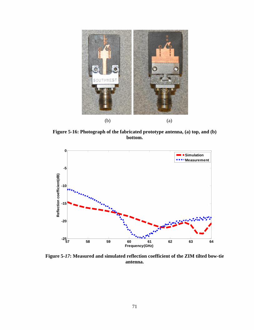
71
(b) (a)
Figure 5-16: Photograph of the fabricated prototype antenna, (a) top, and (b)
bottom.
Figure 5-17: Measured and simulated reflection coefficient of the ZIM tilted bow-tie
antenna.
57 58 59 60 61 62 63 64-25
-20
-15
-10
-5
0
Frequency(GHz)
Re
fle
cti
on
co
eff
icie
nt(
dB
)
Simulation
Measurement
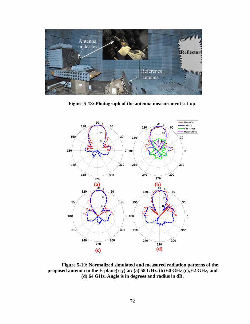
72
Figure 5-18: Photograph of the antenna measurement set-up.
-20
-10
0
30
210
60
240
90
270
120
300
150
330
180 0
(a) (b)
10
20
0
30
210
60
240
90
270
120
300
150
330
180 0
10
20
0
30
210
60
240
90
270
120
300
150
330
180 0
(c) (d)
-20
-10
0
30
210
60
240
90
270
120
300
150
330
180 0
Meas Co
Sim-Co
Sim-Cross
Meas-Cross
Figure 5-19: Normalized simulated and measured radiation patterns of the
proposed antenna in the E-plane(x-y) at: (a) 58 GHz, (b) 60 GHz (c), 62 GHz, and
(d) 64 GHz. Angle is in degrees and radius in dB.
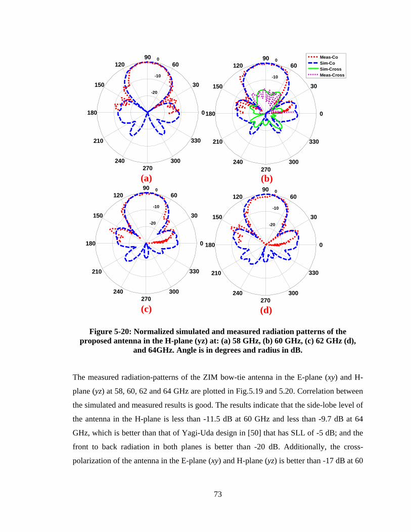
73
-20
-10
0
30
210
60
240
90
270
120
300
150
330
180 0
-20
-10
0
30
210
60
240
90
270
120
300
150
330
180 0
Meas-Co
Sim-Co
Sim-Cross
Meas-Cross
(a) (b)
-20
-10
0
30
210
60
240
90
270
120
300
150
330
180 0
-20
-10
0
30
210
60
240
90
270
120
300
150
330
180 0
(c) (d)
Figure 5-20: Normalized simulated and measured radiation patterns of the
proposed antenna in the H-plane (yz) at: (a) 58 GHz, (b) 60 GHz, (c) 62 GHz (d),
and 64GHz. Angle is in degrees and radius in dB.
The measured radiation-patterns of the ZIM bow-tie antenna in the E-plane (xy) and H-
plane (yz) at 58, 60, 62 and 64 GHz are plotted in Fig.5.19 and 5.20. Correlation between
the simulated and measured results is good. The results indicate that the side-lobe level of
the antenna in the H-plane is less than -11.5 dB at 60 GHz and less than -9.7 dB at 64
GHz, which is better than that of Yagi-Uda design in [50] that has SLL of -5 dB; and the
front to back radiation in both planes is better than -20 dB. Additionally, the cross-
polarization of the antenna in the E-plane (xy) and H-plane (yz) is better than -17 dB at 60
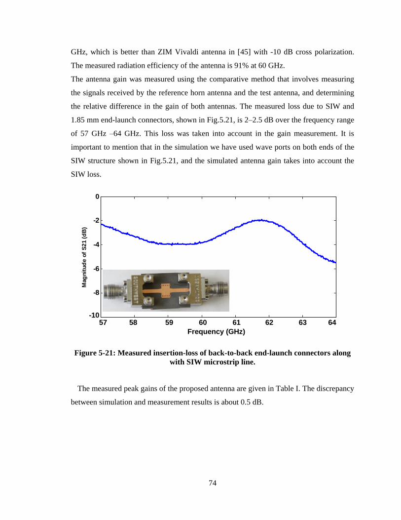
74
GHz, which is better than ZIM Vivaldi antenna in [45] with -10 dB cross polarization.
The measured radiation efficiency of the antenna is 91% at 60 GHz.
The antenna gain was measured using the comparative method that involves measuring
the signals received by the reference horn antenna and the test antenna, and determining
the relative difference in the gain of both antennas. The measured loss due to SIW and
1.85 mm end-launch connectors, shown in Fig.5.21, is 2–2.5 dB over the frequency range
of 57 GHz –64 GHz. This loss was taken into account in the gain measurement. It is
important to mention that in the simulation we have used wave ports on both ends of the
SIW structure shown in Fig.5.21, and the simulated antenna gain takes into account the
SIW loss.
5.7 5.8 5.9 6 6.1 6.2 6.3 6.4
x 1010
-10
-8
-6
-4
-2
0
Frequency(GHz)
Mag
nit
ud
e o
f S
21
(d
B)
57 58 59 60 61 62 63 64
Frequency (GHz)
-10
Figure 5-21: Measured insertion-loss of back-to-back end-launch connectors along
with SIW microstrip line.
The measured peak gains of the proposed antenna are given in Table I. The discrepancy
between simulation and measurement results is about 0.5 dB.
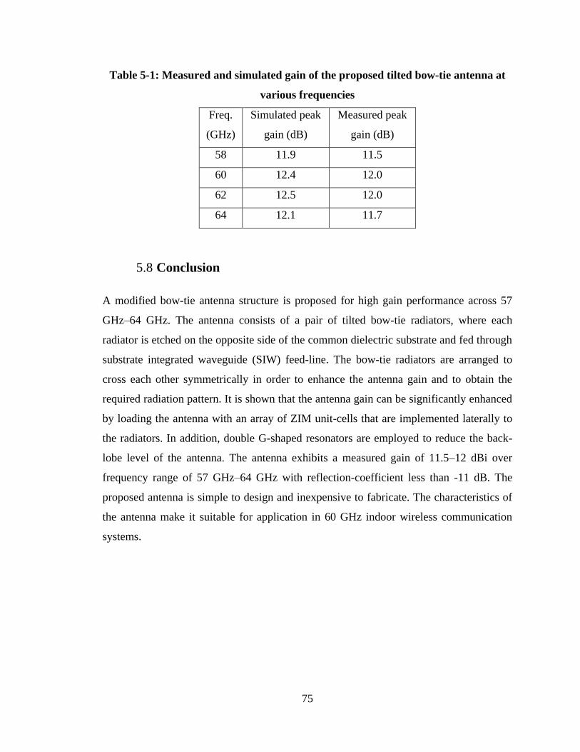
75
Table 5-1: Measured and simulated gain of the proposed tilted bow-tie antenna at
various frequencies
Freq.
(GHz)
Simulated peak
gain (dB)
Measured peak
gain (dB)
58 11.9 11.5
60 12.4 12.0
62 12.5 12.0
64 12.1 11.7
5.8 Conclusion
A modified bow-tie antenna structure is proposed for high gain performance across 57
GHz–64 GHz. The antenna consists of a pair of tilted bow-tie radiators, where each
radiator is etched on the opposite side of the common dielectric substrate and fed through
substrate integrated waveguide (SIW) feed-line. The bow-tie radiators are arranged to
cross each other symmetrically in order to enhance the antenna gain and to obtain the
required radiation pattern. It is shown that the antenna gain can be significantly enhanced
by loading the antenna with an array of ZIM unit-cells that are implemented laterally to
the radiators. In addition, double G-shaped resonators are employed to reduce the back-
lobe level of the antenna. The antenna exhibits a measured gain of 11.5–12 dBi over
frequency range of 57 GHz–64 GHz with reflection-coefficient less than -11 dB. The
proposed antenna is simple to design and inexpensive to fabricate. The characteristics of
the antenna make it suitable for application in 60 GHz indoor wireless communication
systems.
76
Chapter 6 Beam Deflection Using Gradient refractive index media for
60 GHz end-fire antenna
6.1 Introduction
The 60GHz unlicensed frequency band has attracted considerable attention in the light of
its large frequency band (57–64 GHz) and high absorption loss. Operation at this
frequency band enables reduction of interference as well as greater frequency reuse
factor. These characteristics make it very attractive for short-range wireless indoor
communication and multi Gb/s data rate systems. One major challenge in the
implementation of 60GHz wireless systems is high path-loss, which can be compensated
using high gain antennas. However, high gain antennas possess a narrow beamwidth that
makes beam alignment difficult, especially where the location of transmitter or receiver is
not fixed. Adaptive antennas provide a solution to negate this issue but this is costly [51]-
[52]. Another viable technique to re-direct the main beam towards specific direction is
based on liquid crystal phased array using reflection-type phase shifter [53] however the
scanning is limited to 27o. This can be overcome using a beam forming network like the
Butler matrix [54]-[56] but this can increase the overall system size.
The planar 60 GHz switched beam patch antenna in [54] is implemented using a 4×4
Butler matrix that can switch the direction of the main beam in four directions. This
antenna has dimensions 13.1×9.75 mm2.To realize 2D beam scanning, the authors in [55]
used a switched beam network using a pair of 4×4 Butler matrix interconnected to four
hybrid couplers, which are connected to a 2×4 patch array to produce eight beam-states.
Loading a varactor diode between parasitic elements is another approach to steer the
main beam in the azimuth plane with maximum peak gain of 5.9 dB [57]. Another
promising method involves integrating a dielectric lens in front of an antenna array for
implementing beam steering at millimeter-waves [58,5 9].
More recently, the authors in [21] integrated a 4×3 array of high refractive-index
metamaterial unit-cells with a bow-tie antenna to demonstrate the feasibility of tilting the
77
direction of the antenna main beam for C-band applications; however the refractive index
of the unit-cell could not be altered. With this technique, the antenna exhibits a gain
enhancement of 1.5–2.5 dBi over the frequency range of 7.3–7.7 GHz but the angle of the
main beam is limited to 17o.The authors in [60] presented a passive fixed beam forming
network (BFN) by applying a 4×4 Butler matrix consisting a SIW phase shifter and
coupler to tilt the main beam in both E- and H-planes by 20o. The antenna consists of a
multi-layer structure which is complex to construct and occupies a volume of 2.86o
×2.86o ×0.22o.
This chapter presents an inexpensive beam tilting technique using a gradient
refractive-index metamaterial (GRIM) unit-cell to deflect the direction of the main beam
of a 60 GHz end-fire dipole antenna at angles of ±56o, ±26o, and 0o. The unique feature of
the GRIM unit-cell is its refractive-index can be altered by varying the stub loading
without affecting the overall dimensions of the unit-cell. The proposed antenna consists
of a printed dipole antenna incorporating 5×4 array of GRIM unit-cells which are directly
integrated onto the antenna along the azimuth plane. Measurements show the deflection
of the main beam at angle +26o and -26o with respect to the end-fire direction is
accompanied by peak gain of 10.2 dB and 9.7 dB, respectively. The antenna radiates with
an efficiency of 88% at 60 GHz, which is much higher than the BFN structure in [60] that
has an efficiency of 70% at 26.5 GHz. In addition, the proposed antenna exhibits a higher
beam tilt angle and a gain enhancement of 4 dB over the frequency range of 57–64 GHz
than that in [21] which operates at C-band.
6.2 Beam deflection technique
When an electromagnetic wave (EM) in one medium enters another medium of a
different refractive index the wave refracts as predicted by Snell‟s law. In [61] it is shown
that a 2D array of resonators with subwavelength separation results in phase
discontinuities in the propagating EM wave as it traverses the interface between two
media as predicted by the generalized Snell‟s law:
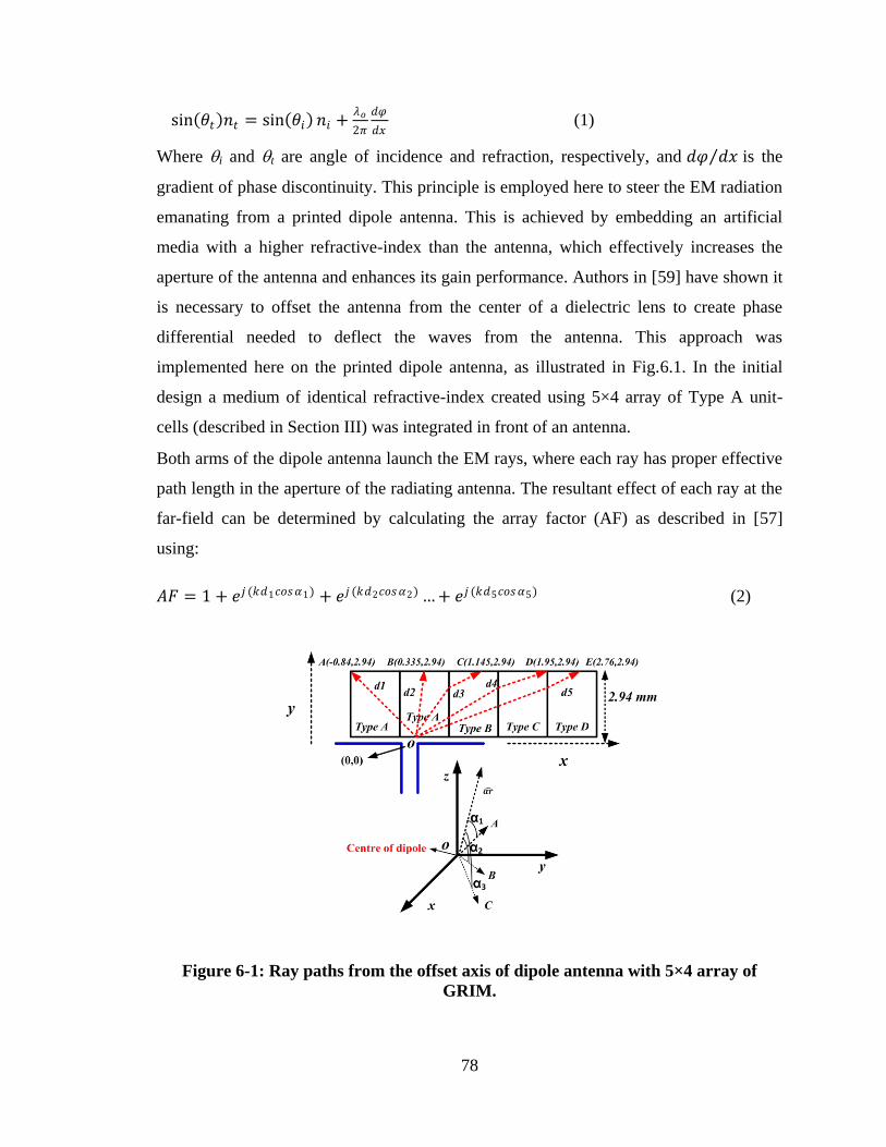
78
sin 𝜃𝑡 𝑛𝑡 = sin 𝜃𝑖 𝑛𝑖 +𝜆𝑜
2𝜋
𝑑𝜑
𝑑𝑥 (1)
Where i and t are angle of incidence and refraction, respectively, and 𝑑𝜑 𝑑𝑥 is the
gradient of phase discontinuity. This principle is employed here to steer the EM radiation
emanating from a printed dipole antenna. This is achieved by embedding an artificial
media with a higher refractive-index than the antenna, which effectively increases the
aperture of the antenna and enhances its gain performance. Authors in [59] have shown it
is necessary to offset the antenna from the center of a dielectric lens to create phase
differential needed to deflect the waves from the antenna. This approach was
implemented here on the printed dipole antenna, as illustrated in Fig.6.1. In the initial
design a medium of identical refractive-index created using 5×4 array of Type A unit-
cells (described in Section III) was integrated in front of an antenna.
Both arms of the dipole antenna launch the EM rays, where each ray has proper effective
path length in the aperture of the radiating antenna. The resultant effect of each ray at the
far-field can be determined by calculating the array factor (AF) as described in [57]
using:
𝐴𝐹 = 1 + 𝑒𝑗 (𝑘𝑑1𝑐𝑜𝑠𝛼1) + 𝑒𝑗 (𝑘𝑑2𝑐𝑜𝑠𝛼2) … + 𝑒𝑗 (𝑘𝑑5𝑐𝑜𝑠𝛼5) (2)
Figure 6-1: Ray paths from the offset axis of dipole antenna with 5×4 array of
GRIM.
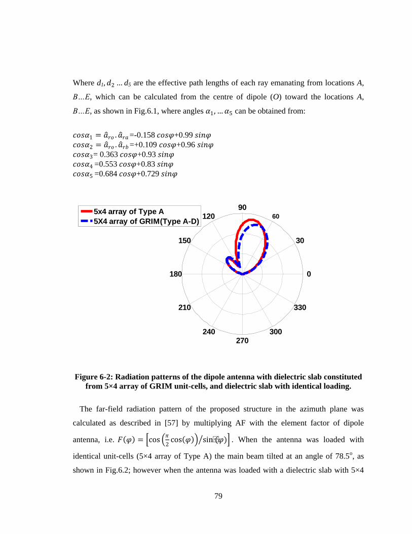
79
Where d1, 𝑑2 … d5 are the effective path lengths of each ray emanating from locations A,
B…E, which can be calculated from the centre of dipole (O) toward the locations A,
B…E, as shown in Fig.6.1, where angles 𝛼1 , …𝛼5 can be obtained from:
𝑐𝑜𝑠𝛼1 = 𝑎 𝑟𝑜 . 𝑎 𝑟𝑎 =-0.158 𝑐𝑜𝑠𝜑+0.99 𝑠𝑖𝑛𝜑
𝑐𝑜𝑠𝛼2 = 𝑎 𝑟𝑜 . 𝑎 𝑟𝑏 =+0.109 𝑐𝑜𝑠𝜑+0.96 𝑠𝑖𝑛𝜑
𝑐𝑜𝑠𝛼3= 0.363 𝑐𝑜𝑠𝜑+0.93 𝑠𝑖𝑛𝜑
𝑐𝑜𝑠𝛼4 =0.553 𝑐𝑜𝑠𝜑+0.83 𝑠𝑖𝑛𝜑
𝑐𝑜𝑠𝛼5 =0.684 𝑐𝑜𝑠𝜑+0.729 𝑠𝑖𝑛𝜑
Figure 6-2: Radiation patterns of the dipole antenna with dielectric slab constituted
from 5×4 array of GRIM unit-cells, and dielectric slab with identical loading.
The far-field radiation pattern of the proposed structure in the azimuth plane was
calculated as described in [57] by multiplying AF with the element factor of dipole
antenna, i.e. 𝐹 𝜑 = cos 𝜋
2cos 𝜑 sin(𝜑) . When the antenna was loaded with
identical unit-cells (5×4 array of Type A) the main beam tilted at an angle of 78.5o, as
shown in Fig.6.2; however when the antenna was loaded with a dielectric slab with 5×4
30
210
60
240
90
270
120
300
150
330
180 0
5x4 array of Type A
5X4 array of GRIM(Type A-D)
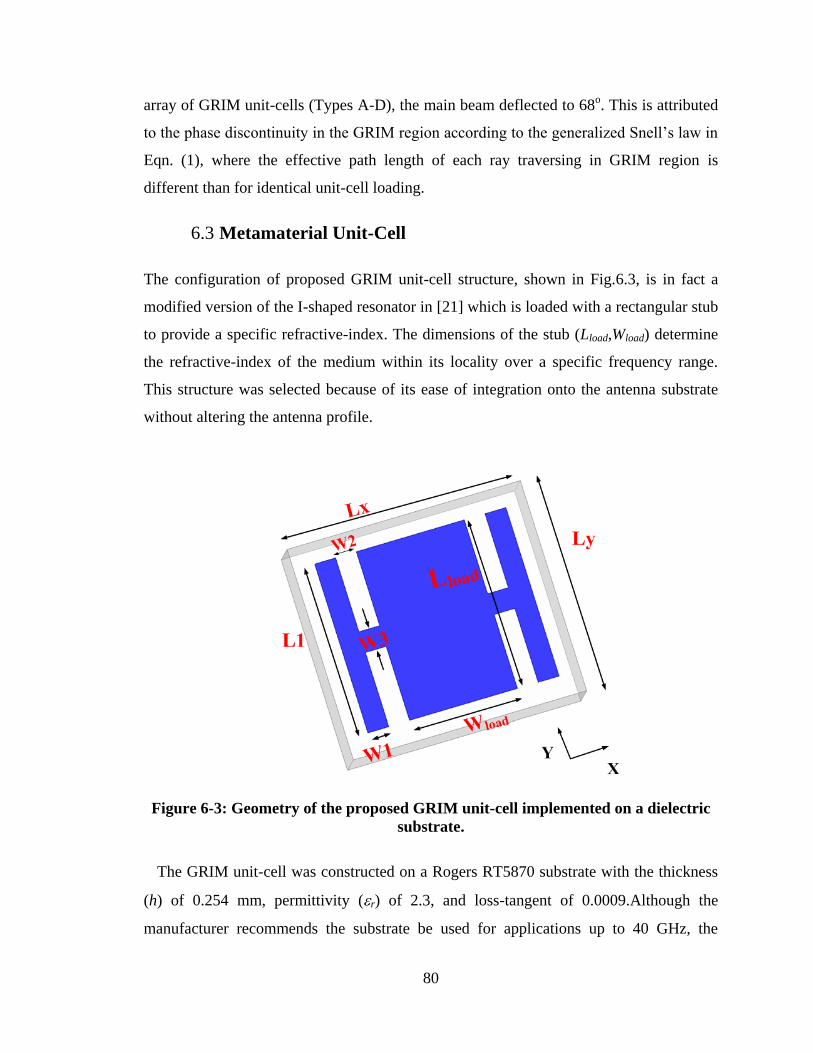
80
array of GRIM unit-cells (Types A-D), the main beam deflected to 68o. This is attributed
to the phase discontinuity in the GRIM region according to the generalized Snell‟s law in
Eqn. (1), where the effective path length of each ray traversing in GRIM region is
different than for identical unit-cell loading.
6.3 Metamaterial Unit-Cell
The configuration of proposed GRIM unit-cell structure, shown in Fig.6.3, is in fact a
modified version of the I-shaped resonator in [21] which is loaded with a rectangular stub
to provide a specific refractive-index. The dimensions of the stub (Lload,Wload) determine
the refractive-index of the medium within its locality over a specific frequency range.
This structure was selected because of its ease of integration onto the antenna substrate
without altering the antenna profile.
Figure 6-3: Geometry of the proposed GRIM unit-cell implemented on a dielectric
substrate.
The GRIM unit-cell was constructed on a Rogers RT5870 substrate with the thickness
(h) of 0.254 mm, permittivity (r) of 2.3, and loss-tangent of 0.0009.Although the
manufacturer recommends the substrate be used for applications up to 40 GHz, the
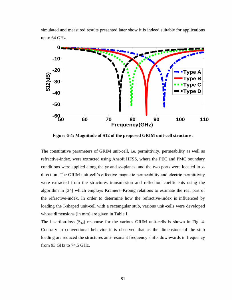
81
simulated and measured results presented later show it is indeed suitable for applications
up to 64 GHz.
Figure 6-4: Magnitude of S12 of the proposed GRIM unit-cell structure .
The constitutive parameters of GRIM unit-cell, i.e. permittivity, permeability as well as
refractive-index, were extracted using Ansoft HFSS, where the PEC and PMC boundary
conditions were applied along the yz and xy-planes, and the two ports were located in x-
direction. The GRIM unit-cell‟s effective magnetic permeability and electric permittivity
were extracted from the structures transmission and reflection coefficients using the
algorithm in [34] which employs Kramers–Kronig relations to estimate the real part of
the refractive-index. In order to determine how the refractive-index is influenced by
loading the I-shaped unit-cell with a rectangular stub, various unit-cells were developed
whose dimensions (in mm) are given in Table I.
The insertion-loss (S12) response for the various GRIM unit-cells is shown in Fig. 4.
Contrary to conventional behavior it is observed that as the dimensions of the stub
loading are reduced the structures anti-resonant frequency shifts downwards in frequency
from 93 GHz to 74.5 GHz.
50 60 70 80 90 100 110-60
-50
-40
-30
-20
-10
0
Frequency(GHz)
S12(d
B)
Type A
Type B
Type C
Type D
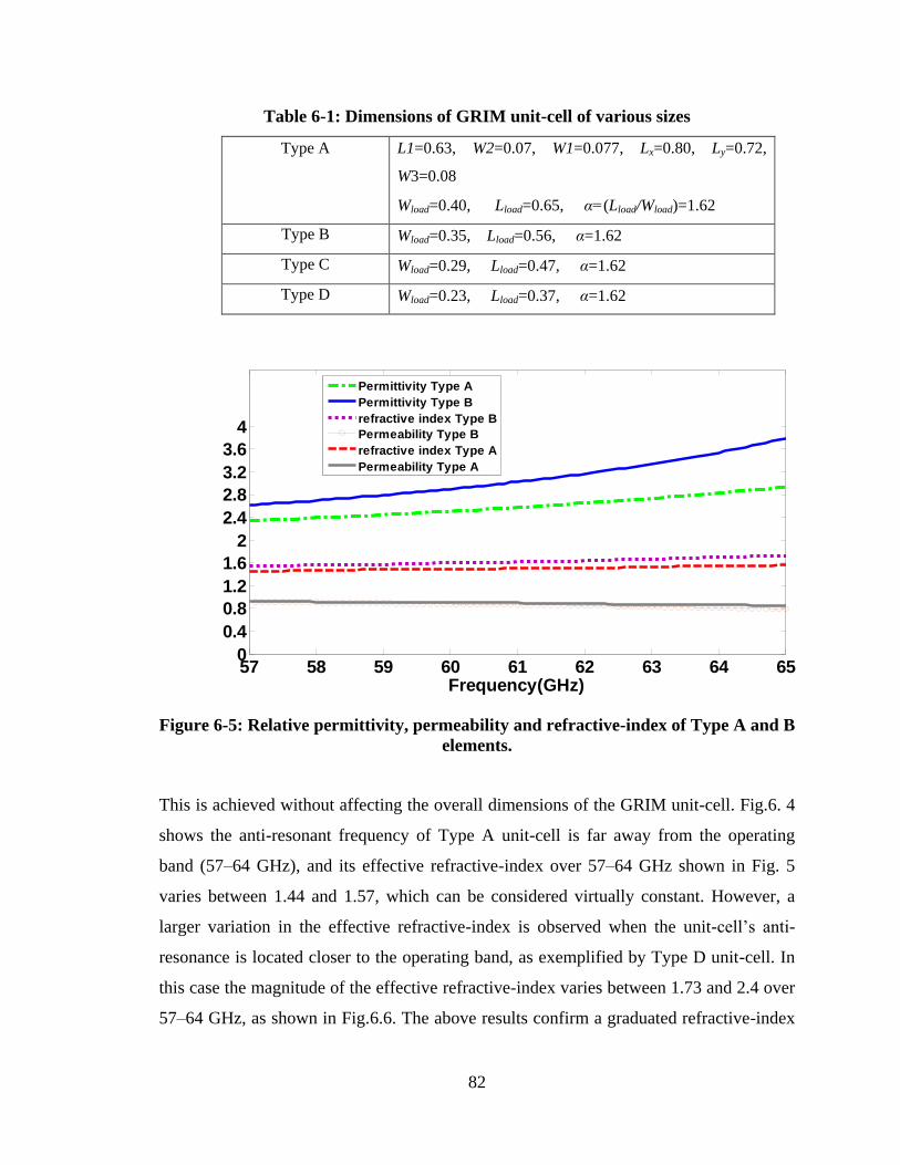
82
Table 6-1: Dimensions of GRIM unit-cell of various sizes
Type A L1=0.63, W2=0.07, W1=0.077, Lx=0.80, Ly=0.72,
W3=0.08
Wload=0.40, Lload=0.65, α=(Lload/Wload)=1.62
Type B Wload=0.35, Lload=0.56, α=1.62
Type C Wload=0.29, Lload=0.47, α=1.62
Type D Wload=0.23, Lload=0.37, α=1.62
Figure 6-5: Relative permittivity, permeability and refractive-index of Type A and B
elements.
This is achieved without affecting the overall dimensions of the GRIM unit-cell. Fig.6. 4
shows the anti-resonant frequency of Type A unit-cell is far away from the operating
band (57–64 GHz), and its effective refractive-index over 57–64 GHz shown in Fig. 5
varies between 1.44 and 1.57, which can be considered virtually constant. However, a
larger variation in the effective refractive-index is observed when the unit-cell‟s anti-
resonance is located closer to the operating band, as exemplified by Type D unit-cell. In
this case the magnitude of the effective refractive-index varies between 1.73 and 2.4 over
57–64 GHz, as shown in Fig.6.6. The above results confirm a graduated refractive-index
57 58 59 60 61 62 63 64 650
0.4
0.8
1.2
1.6
2
2.4
2.8
3.2
3.6
4
Frequency(GHz)
Permittivity Type A
Permittivity Type B
refractive index Type B
Permeability Type B
refractive index Type A
Permeability Type A
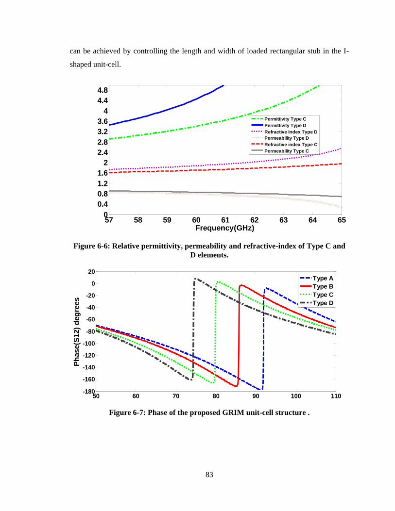
83
can be achieved by controlling the length and width of loaded rectangular stub in the I-
shaped unit-cell.
Figure 6-6: Relative permittivity, permeability and refractive-index of Type C and
D elements.
Figure 6-7: Phase of the proposed GRIM unit-cell structure .
57 58 59 60 61 62 63 64 650
0.4
0.8
1.2
1.6
2
2.4
2.8
3.2
3.6
4
4.4
4.8
Frequency(GHz)
Permittivity Type C
Permittivity Type D
Refractive Index Type D
Permeability Type D
Refractive index Type C
Permeability Type C
50 60 70 80 90 100 110-180
-160
-140
-120
-100
-80
-60
-40
-20
0
20
Frequenc(GHz)
Ph
ase(S
12)
deg
rees
Type A
Type B
Type C
Type D
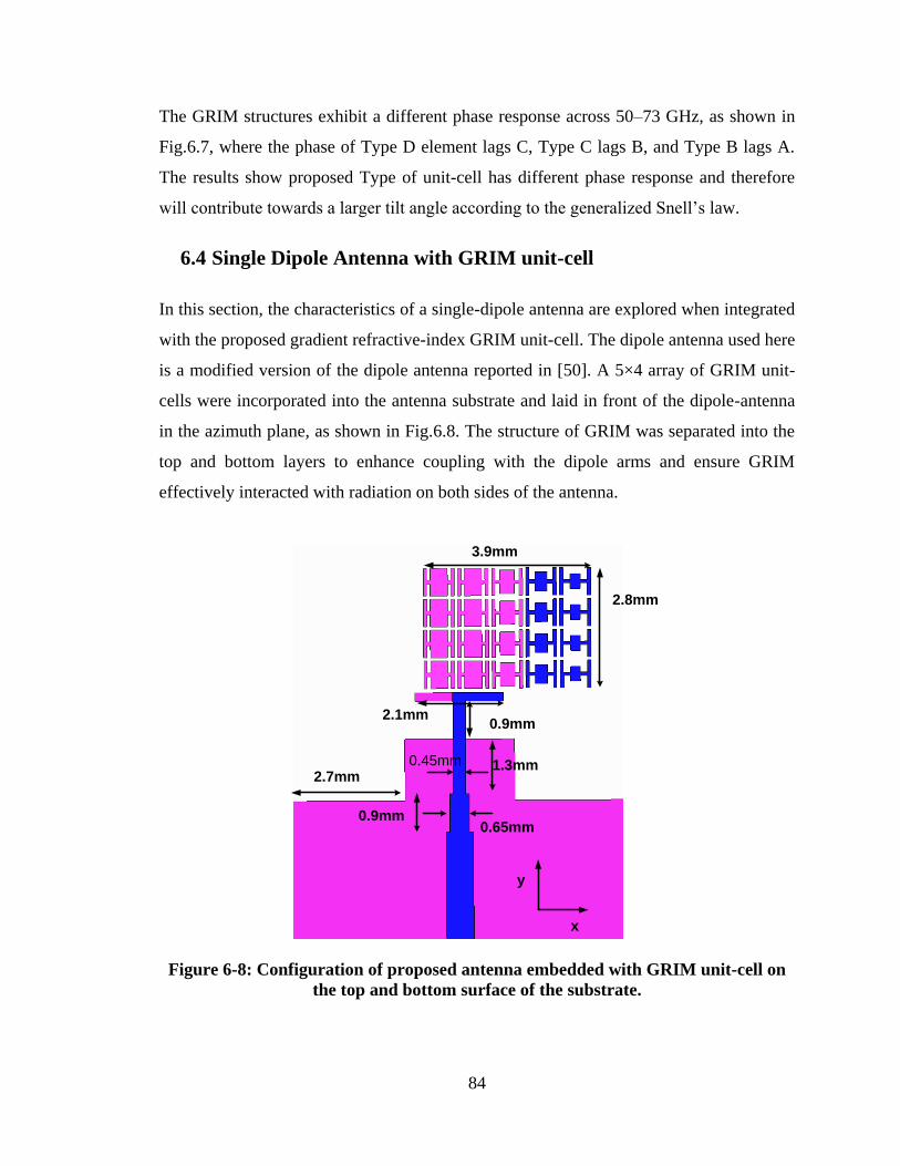
84
The GRIM structures exhibit a different phase response across 50–73 GHz, as shown in
Fig.6.7, where the phase of Type D element lags C, Type C lags B, and Type B lags A.
The results show proposed Type of unit-cell has different phase response and therefore
will contribute towards a larger tilt angle according to the generalized Snell‟s law.
6.4 Single Dipole Antenna with GRIM unit-cell
In this section, the characteristics of a single-dipole antenna are explored when integrated
with the proposed gradient refractive-index GRIM unit-cell. The dipole antenna used here
is a modified version of the dipole antenna reported in [50]. A 5×4 array of GRIM unit-
cells were incorporated into the antenna substrate and laid in front of the dipole-antenna
in the azimuth plane, as shown in Fig.6.8. The structure of GRIM was separated into the
top and bottom layers to enhance coupling with the dipole arms and ensure GRIM
effectively interacted with radiation on both sides of the antenna.
2.8mm
3.9mm
2.1mm0.9mm
2.7mm
0.9mm
0.45mm
0.65mm
1.3mm
x
y
Figure 6-8: Configuration of proposed antenna embedded with GRIM unit-cell on
the top and bottom surface of the substrate.
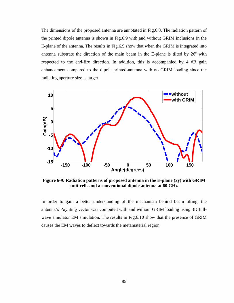
85
The dimensions of the proposed antenna are annotated in Fig.6.8. The radiation pattern of
the printed dipole antenna is shown in Fig.6.9 with and without GRIM inclusions in the
E-plane of the antenna. The results in Fig.6.9 show that when the GRIM is integrated into
antenna substrate the direction of the main beam in the E-plane is tilted by 26o with
respected to the end-fire direction. In addition, this is accompanied by 4 dB gain
enhancement compared to the dipole printed-antenna with no GRIM loading since the
radiating aperture size is larger.
Figure 6-9: Radiation patterns of proposed antenna in the E-plane (xy) with GRIM
unit-cells and a conventional dipole antenna at 60 GHz
In order to gain a better understanding of the mechanism behind beam tilting, the
antenna‟s Poynting vector was computed with and without GRIM loading using 3D full-
wave simulator EM simulation. The results in Fig.6.10 show that the presence of GRIM
causes the EM waves to deflect towards the metamaterial region.
-150 -100 -50 0 50 100 150-15
-10
-5
0
5
10
Angle(degrees)
Gain
(dB
)
without
with GRIM
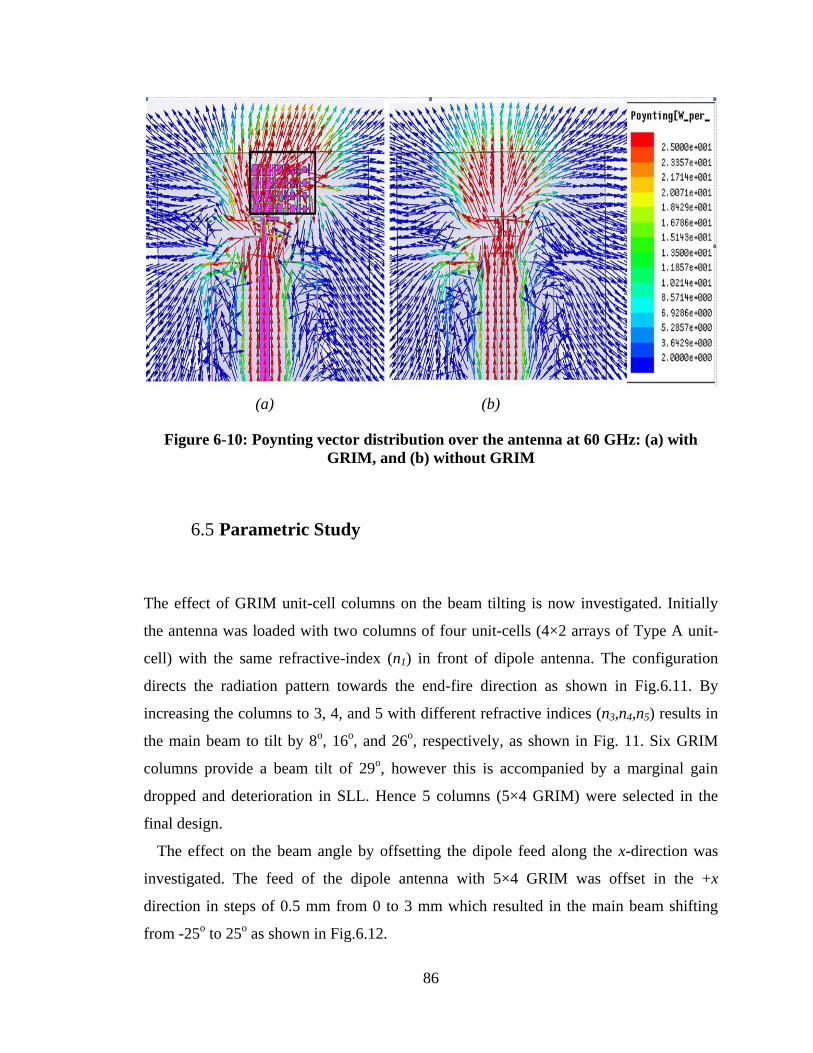
86
(a) (b)
Figure 6-10: Poynting vector distribution over the antenna at 60 GHz: (a) with
GRIM, and (b) without GRIM
6.5 Parametric Study
The effect of GRIM unit-cell columns on the beam tilting is now investigated. Initially
the antenna was loaded with two columns of four unit-cells (4×2 arrays of Type A unit-
cell) with the same refractive-index (n1) in front of dipole antenna. The configuration
directs the radiation pattern towards the end-fire direction as shown in Fig.6.11. By
increasing the columns to 3, 4, and 5 with different refractive indices (n3,n4,n5) results in
the main beam to tilt by 8o, 16
o, and 26
o, respectively, as shown in Fig. 11. Six GRIM
columns provide a beam tilt of 29o, however this is accompanied by a marginal gain
dropped and deterioration in SLL. Hence 5 columns (5×4 GRIM) were selected in the
final design.
The effect on the beam angle by offsetting the dipole feed along the x-direction was
investigated. The feed of the dipole antenna with 5×4 GRIM was offset in the +x
direction in steps of 0.5 mm from 0 to 3 mm which resulted in the main beam shifting
from -25o to 25
o as shown in Fig.6.12.
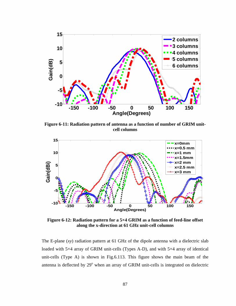
87
Figure 6-11: Radiation pattern of antenna as a function of number of GRIM unit-
cell columns
Figure 6-12: Radiation pattern for a 5×4 GRIM as a function of feed-line offset
along the x-direction at 61 GHz unit-cell columns
The E-plane (xy) radiation pattern at 61 GHz of the dipole antenna with a dielectric slab
loaded with 5×4 array of GRIM unit-cells (Types A-D), and with 5×4 array of identical
unit-cells (Type A) is shown in Fig.6.113. This figure shows the main beam of the
antenna is deflected by 29o when an array of GRIM unit-cells is integrated on dielectric
-150 -100 -50 0 50 100 150-10
-5
0
5
10
15
Angle(Degrees)
Gain
(dB
)
2 columns
3 columns
4 columns
5 columns
6 columns
-150 -100 -50 0 50 100 150-10
-5
0
5
10
15
Angle(Degrees)
Ga
in(d
Bi)
x=0mm
x=0.5 mm
x=1 mm
x=1.5mm
x=2 mm
x=2.5 mm
x=3 mm
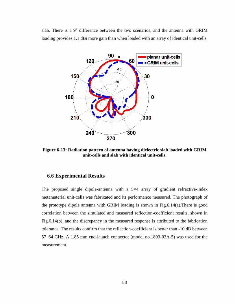
88
slab. There is a 9o difference between the two scenarios, and the antenna with GRIM
loading provides 1.1 dBi more gain than when loaded with an array of identical unit-cells.
Figure 6-13: Radiation pattern of antenna having dielectric slab loaded with GRIM
unit-cells and slab with identical unit-cells.
6.6 Experimental Results
The proposed single dipole-antenna with a 5×4 array of gradient refractive-index
metamaterial unit-cells was fabricated and its performance measured. The photograph of
the prototype dipole antenna with GRIM loading is shown in Fig.6.14(a).There is good
correlation between the simulated and measured reflection-coefficient results, shown in
Fig.6.14(b), and the discrepancy in the measured response is attributed to the fabrication
tolerance. The results confirm that the reflection-coefficient is better than -10 dB between
57–64 GHz. A 1.85 mm end-launch connector (model no.1893-03A-5) was used for the
measurement.
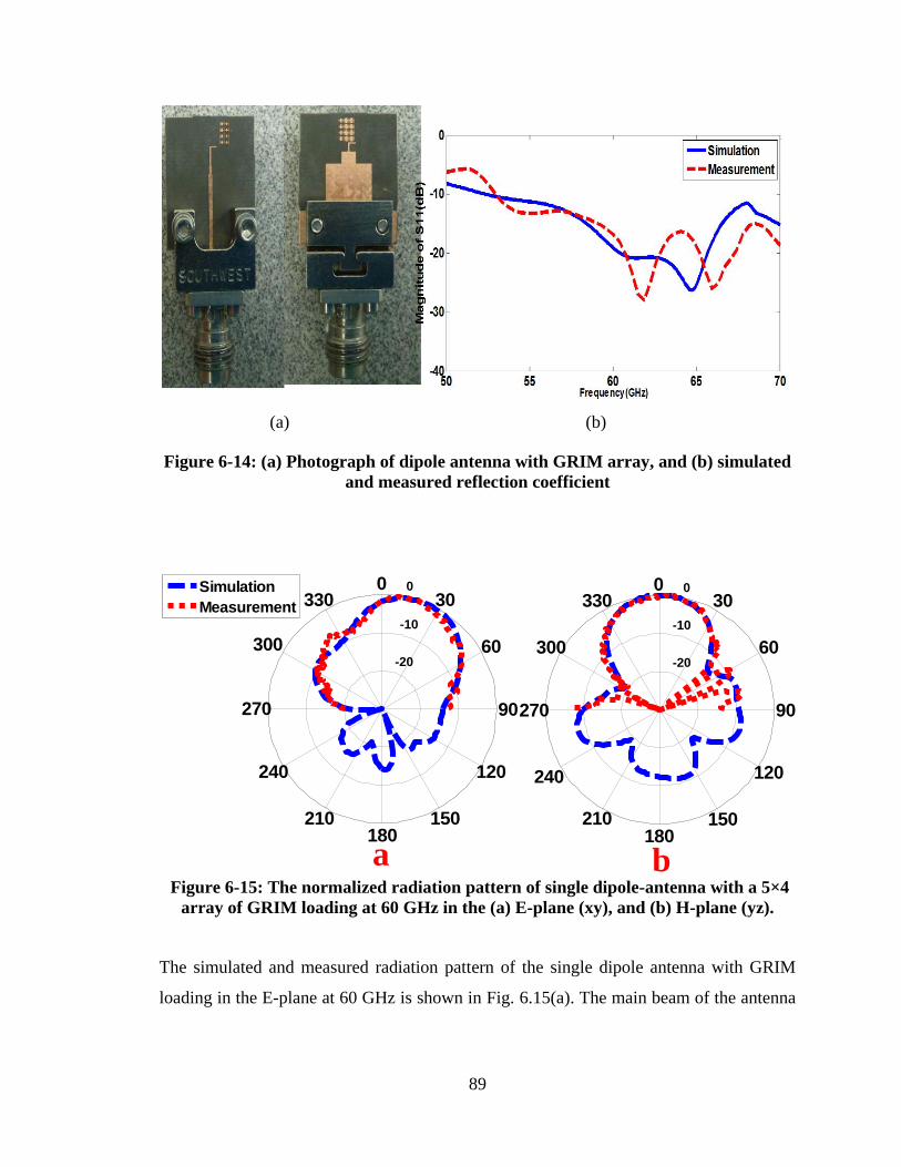
89
(a) (b)
Figure 6-14: (a) Photograph of dipole antenna with GRIM array, and (b) simulated
and measured reflection coefficient
-20
-10
0
60
240
30
210
0
180
330
150
300
120
270 90
Simulation
Measurement
-20
-10
0
60
240
30
210
0
180
330
150
300
120
270 90
a b Figure 6-15: The normalized radiation pattern of single dipole-antenna with a 5×4
array of GRIM loading at 60 GHz in the (a) E-plane (xy), and (b) H-plane (yz).
The simulated and measured radiation pattern of the single dipole antenna with GRIM
loading in the E-plane at 60 GHz is shown in Fig. 6.15(a). The main beam of the antenna
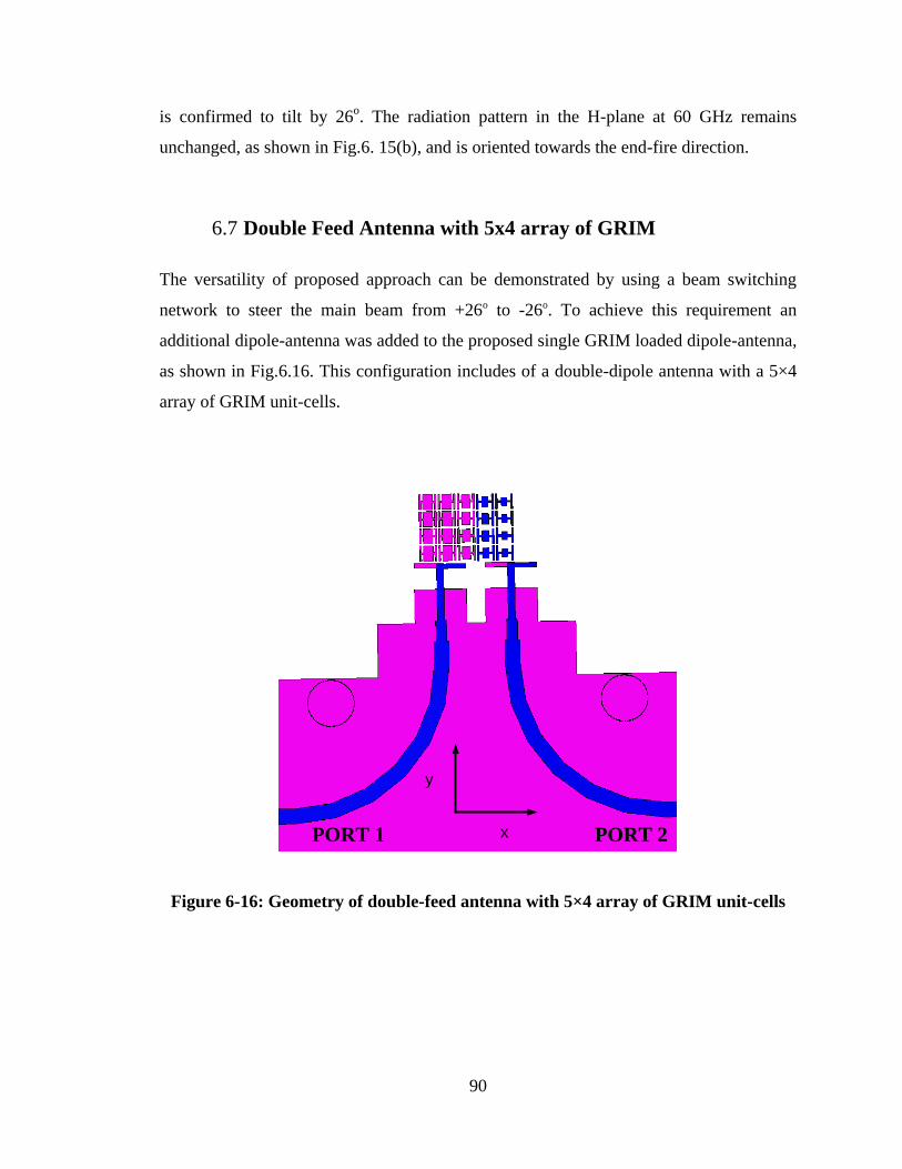
90
is confirmed to tilt by 26o. The radiation pattern in the H-plane at 60 GHz remains
unchanged, as shown in Fig.6. 15(b), and is oriented towards the end-fire direction.
6.7 Double Feed Antenna with 5x4 array of GRIM
The versatility of proposed approach can be demonstrated by using a beam switching
network to steer the main beam from +26o to -26o. To achieve this requirement an
additional dipole-antenna was added to the proposed single GRIM loaded dipole-antenna,
as shown in Fig.6.16. This configuration includes of a double-dipole antenna with a 5×4
array of GRIM unit-cells.
PORT 1 PORT 2x
y
Figure 6-16: Geometry of double-feed antenna with 5×4 array of GRIM unit-cells
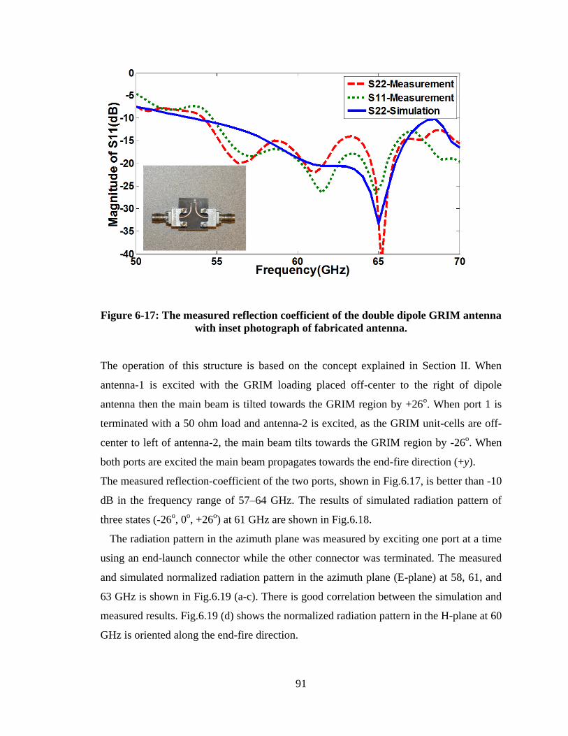
91
Figure 6-17: The measured reflection coefficient of the double dipole GRIM antenna
with inset photograph of fabricated antenna.
The operation of this structure is based on the concept explained in Section II. When
antenna-1 is excited with the GRIM loading placed off-center to the right of dipole
antenna then the main beam is tilted towards the GRIM region by +26o. When port 1 is
terminated with a 50 ohm load and antenna-2 is excited, as the GRIM unit-cells are off-
center to left of antenna-2, the main beam tilts towards the GRIM region by -26o. When
both ports are excited the main beam propagates towards the end-fire direction (+y).
The measured reflection-coefficient of the two ports, shown in Fig.6.17, is better than -10
dB in the frequency range of 57–64 GHz. The results of simulated radiation pattern of
three states (-26o, 0
o, +26
o) at 61 GHz are shown in Fig.6.18.
The radiation pattern in the azimuth plane was measured by exciting one port at a time
using an end-launch connector while the other connector was terminated. The measured
and simulated normalized radiation pattern in the azimuth plane (E-plane) at 58, 61, and
63 GHz is shown in Fig.6.19 (a-c). There is good correlation between the simulation and
measured results. Fig.6.19 (d) shows the normalized radiation pattern in the H-plane at 60
GHz is oriented along the end-fire direction.
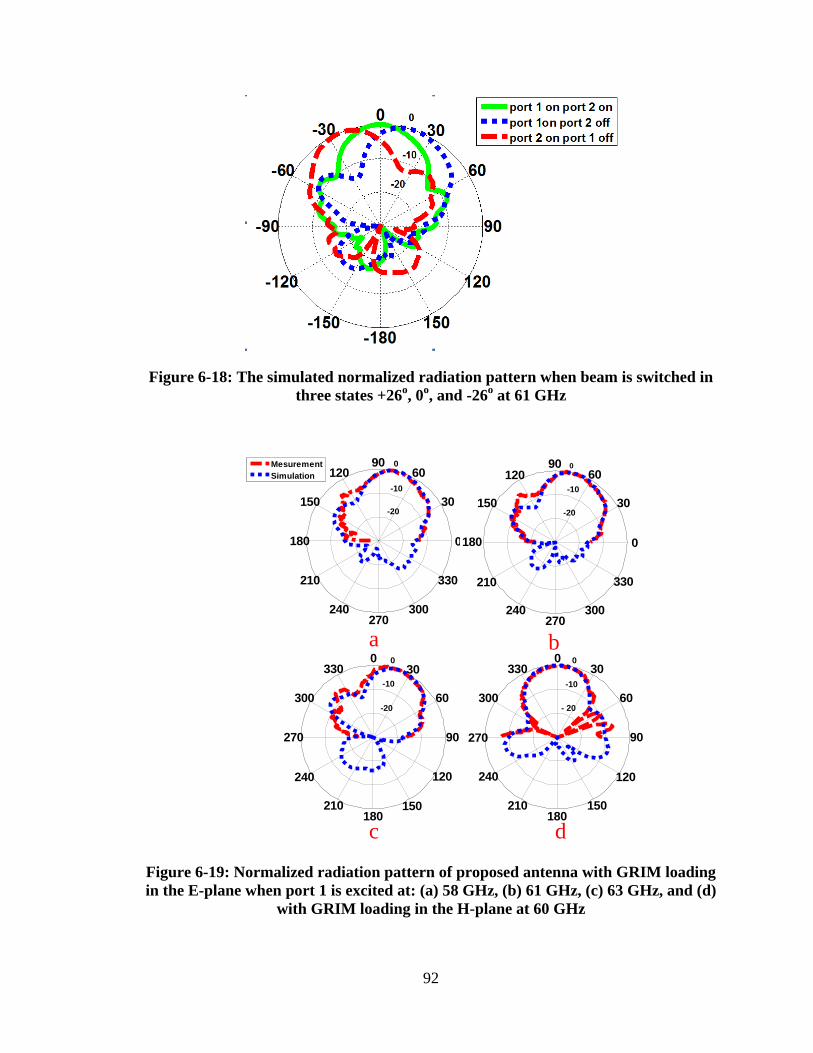
92
Figure 6-18: The simulated normalized radiation pattern when beam is switched in
three states +26o, 0
o, and -26
o at 61 GHz
a b
c d
-20
-10
0
30
210
60
240
90
270
120
300
150
330
180 0
-20
-10
0
60
240
30
210
0
180
330
150
300
120
270 90
- 20
-10
0
60
240
30
210
0
180
330
150
300
120
270 90
-20
-10
0
30
210
60
240
90
270
120
300
150
330
180 0
Mesurement
Simulation
Figure 6-19: Normalized radiation pattern of proposed antenna with GRIM loading
in the E-plane when port 1 is excited at: (a) 58 GHz, (b) 61 GHz, (c) 63 GHz, and (d)
with GRIM loading in the H-plane at 60 GHz
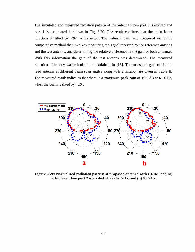
93
The simulated and measured radiation pattern of the antenna when port 2 is excited and
port 1 is terminated is shown in Fig. 6.20. The result confirms that the main beam
direction is tilted by -26o as expected. The antenna gain was measured using the
comparative method that involves measuring the signal received by the reference antenna
and the test antenna, and determining the relative difference in the gain of both antennas.
With this information the gain of the test antenna was determined. The measured
radiation efficiency was calculated as explained in [16]. The measured gain of double
feed antenna at different beam scan angles along with efficiency are given in Table II.
The measured result indicates that there is a maximum peak gain of 10.2 dB at 61 GHz,
when the beam is tilted by +26o.
Figure 6-20: Normalized radiation pattern of proposed antenna with GRIM loading
in E-plane when port 2 is excited at: (a) 59 GHz, and (b) 63 GHz.
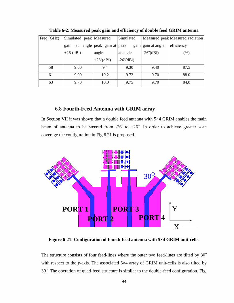
94
Table 6-2: Measured peak gain and efficiency of double feed GRIM antenna
Freq.(GHz) Simulated peak
gain at angle
+26o(dBi)
Measured
peak gain at
angle
+26o(dBi)
Simulated
peak gain
at angle
-26o(dBi)
Measured peak
gain at angle
-26o(dBi)
Measured radiation
efficiency
(%)
58 9.60 9.4 9.30 9.40 87.5
61 9.90 10.2 9.72 9.70 88.0
63 9.70 10.0 9.75 9.70 84.0
6.8 Fourth-Feed Antenna with GRIM array
In Section VII it was shown that a double feed antenna with 5×4 GRIM enables the main
beam of antenna to be steered from -26o
to +26o. In order to achieve greater scan
coverage the configuration in Fig.6.21 is proposed.
PORT 1
PORT 2
PORT 3
PORT 4
30O
X
Y
Figure 6-21: Configuration of fourth-feed antenna with 5×4 GRIM unit-cells.
The structure consists of four feed-lines where the outer two feed-lines are tilted by 30o
with respect to the y-axis. The associated 5×4 array of GRIM unit-cells is also tilted by
30o. The operation of quad-feed structure is similar to the double-feed configuration. Fig.
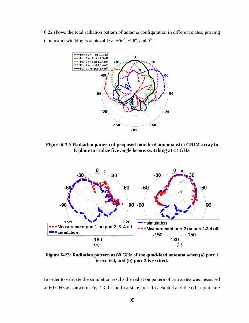
95
6.22 shows the total radiation pattern of antenna configuration in different states, proving
that beam switching is achievable at ±56o, ±26
o, and 0
o.
Figure 6-22: Radiation pattern of proposed four-feed antenna with GRIM array in
E-plane to realize five angle beams switching at 61 GHz.
-20
-10
0
60
-120
30
-150
0
180
-30
150
-60
120
-90 90
simulation
Measurement port 2 on port 1,3,4 off
-20
-10
0
60
-120
30
-150
0
-180
-30
150
-60
120
-90 90
Measurement port 1 on port 2 ,3 ,4 off
simulation
(a) (b)
Figure 6-23: Radiation pattern at 60 GHz of the quad-feed antenna when (a) port 1
is excited, and (b) port 2 is excited.
In order to validate the simulation results the radiation pattern of two states was measured
at 60 GHz as shown in Fig. 23. In the first state, port 1 is excited and the other ports are
- 20
-10
0
60
-120
30
-150
0
-180
-30
150
-60
120
-90 90
Port 4 on Port 2,3,1 off
Port 1 on Port 4,2,3 off
Port 3 on port 1,2,4 off
Port 2 on port 1,3,4 off
Port 2,3 on port 1,4 off
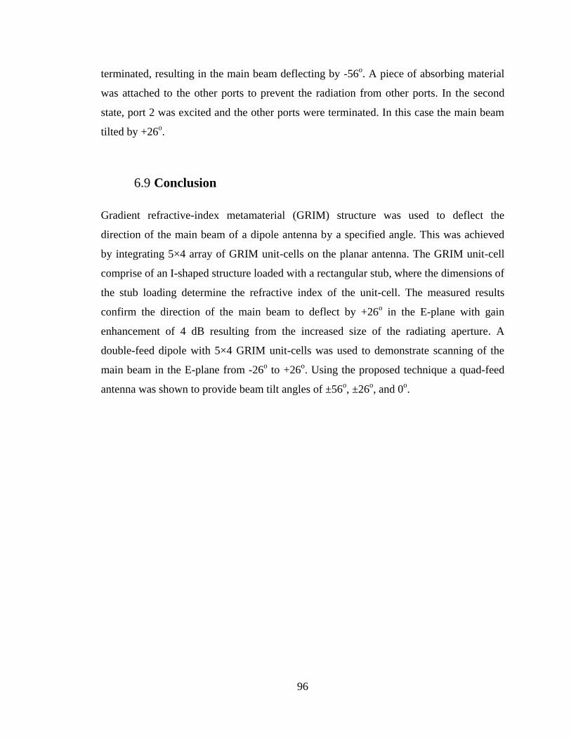
96
terminated, resulting in the main beam deflecting by -56o. A piece of absorbing material
was attached to the other ports to prevent the radiation from other ports. In the second
state, port 2 was excited and the other ports were terminated. In this case the main beam
tilted by +26o.
6.9 Conclusion
Gradient refractive-index metamaterial (GRIM) structure was used to deflect the
direction of the main beam of a dipole antenna by a specified angle. This was achieved
by integrating 5×4 array of GRIM unit-cells on the planar antenna. The GRIM unit-cell
comprise of an I-shaped structure loaded with a rectangular stub, where the dimensions of
the stub loading determine the refractive index of the unit-cell. The measured results
confirm the direction of the main beam to deflect by +26o in the E-plane with gain
enhancement of 4 dB resulting from the increased size of the radiating aperture. A
double-feed dipole with 5×4 GRIM unit-cells was used to demonstrate scanning of the
main beam in the E-plane from -26o to +26
o. Using the proposed technique a quad-feed
antenna was shown to provide beam tilt angles of ±56o, ±26
o, and 0
o.
97
Chapter 7 IMPROVEMENT OF GAIN AND ELEVATION TILT ANGLE
USING METAMATERIAL LOADING FOR MILLIMETER-WAVE
APPLICATION
7.1 Introduction
Communication in the unlicensed 60 GHz band (57–66 GHz) has attracted great attention
for short range multi-Gbps data rate applications such as high definition video streaming
using the IEEE 802.11ad WiGig standard. One distinguishing feature of the 60 GHz
communication is its high propagation loss due to the extremely high carrier frequency
and the oxygen absorption peaks at this frequency band. To combat this, directional
antenna with high directivity gain can be adopted to obtain sufficient link budget [62].
This can be accomplished using antenna arrays that provide advantages of interference
mitigation and multipath suppression [63]. The challenge with directional antennas is
beam alignment between the communication pair. Hence, different approaches have been
proposed to achieve electronic beam steering such as integrated lens antenna technique
for 1-D and 2-D beam scanning at millimeter-wave [64-65]. The drawback feature of this
approach is its overall bulky framework.
1-D and 2-D beam scanning at 30 GHz has been presented in [66] by applying a 2×2 SIW
antenna array implemented with a combination of couplers and phase shifters to tilt the
main beam direction in E-and H-plane by 15 and 45 degrees respectively .
Applying a Butler matrix is another technique to implement a beam forming network at
millimeter wave[67-71].For instance,1D and 2D beam forming network has been
introduced by the authors in [67] utilizing a 1x4 dielectric rod antenna integrated by SIW
folded butler matrix. However the proposed structure has a large dimension and is so
complicated.
The authors in [70] reported a 60 GHz active switched beam antenna consisting of a 4×1
quasi-Yagi array incorporating a 4×4 butler matrix network to obtain a beam steering of
±40o. The overall dimensions of structure are 1.5×1.4 cm.
98
In [71] folded Butler matrix and substrate integrated waveguide radiators are integrated
as a whole by employing the LTCC fabrication process to implement a miniature
substrate integrated multi-beam array antenna. The drawback of this approach is it‟s a
complicated structure and the circuit area is 16.5×14.6 mm2 excluding the additional
feeding structures.
In [32] an array of dipole antenna is mounted perpendicular to an EBG ground-plane to
realize beam tilting for mobile base-stations. With this technique the beam tilt angle is
limited to 25 degrees. The physical size of the antenna at 3.5 GHz is 2.6×0.63×0.84
Comb-line antenna array in [13] provides a tilt angle of 30 degrees at 76 GHz. This
antenna is composed of several rectangular radiating elements directly connected to a
straight feeding microstrip line. The radiating elements are inclined 45 degrees from the
feeding line. The drawback of this configuration is its large physical size, i.e.
15.2×2.5×0.03as it requires two lines of 26-element linear array and its side-lobe is -
5 dB. Authors in [21] have demonstrated the beam tilting phenomenon can be realized
using high refractive-index metamaterial loading which is integrated within the antenna
structure. With this technique the beam tilt angle is limited to 17 degrees in the azimuth-
plane at C-band. In addition, over its operating frequency range the gain of the antenna is
restricted to 1.1–2.4 dB. To increase the tilt angle along with the gain, array of gradient
index of refraction media was embedded in front of a classical dipole antenna at 60 GHz
to deflect the main beam direction in the azimuth plane by 26 degrees in the azimuth
plane with measured gain of 9.45 dBi [22].Additionally, in order to deflect the radiation
pattern of the bow-tie antenna arrays under the horizon an array of split-ring resonator
was integrated in the elevation plane of bow-tie antenna arrays with 30 degrees tilt angle
at 3.5 GHz suitable for next generation of base-station antenna [72].
This chapter presents results on 1-D and 2-D beam deflection over 57-64 GHz using a
novel 3×4 array of high refractive-index metamaterial (HRIM) unit-cells.In section II, the
mechanism behind beam titling is explained followed by the structure of the unit-cell
used in the implementation of high refractive-index. In section III a 3×4 array of HRIM
unit-cells is integrated in the elevation plane of printed single dipole antenna to achieve a
30 degree beam titling. In section V, the proposed technique is applied to a double-feed
dipole to demonstrate the beam deflection cover angles of -30o
and +30o in the elevation
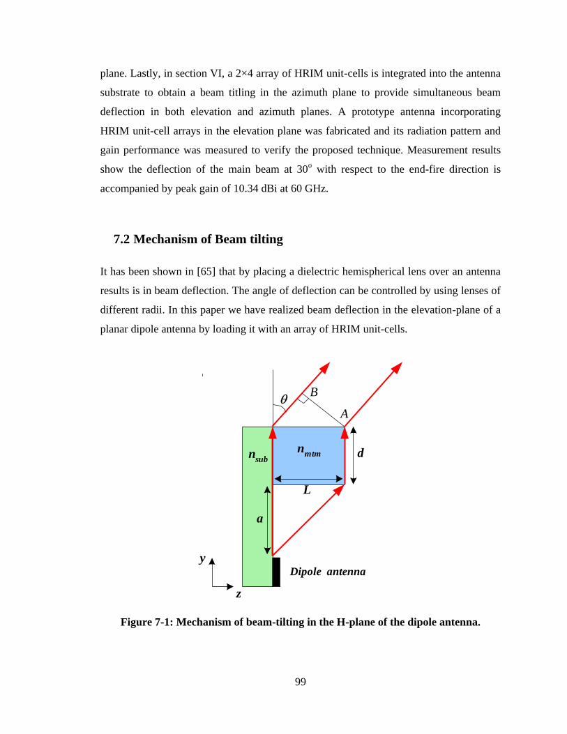
99
plane. Lastly, in section VI, a 2×4 array of HRIM unit-cells is integrated into the antenna
substrate to obtain a beam titling in the azimuth plane to provide simultaneous beam
deflection in both elevation and azimuth planes. A prototype antenna incorporating
HRIM unit-cell arrays in the elevation plane was fabricated and its radiation pattern and
gain performance was measured to verify the proposed technique. Measurement results
show the deflection of the main beam at 30o with respect to the end-fire direction is
accompanied by peak gain of 10.34 dBi at 60 GHz.
7.2 Mechanism of Beam tilting
It has been shown in [65] that by placing a dielectric hemispherical lens over an antenna
results is in beam deflection. The angle of deflection can be controlled by using lenses of
different radii. In this paper we have realized beam deflection in the elevation-plane of a
planar dipole antenna by loading it with an array of HRIM unit-cells.
A
B
d
L
a
Dipole antenna
y
z
nsub
nmtm
Figure 7-1: Mechanism of beam-tilting in the H-plane of the dipole antenna.
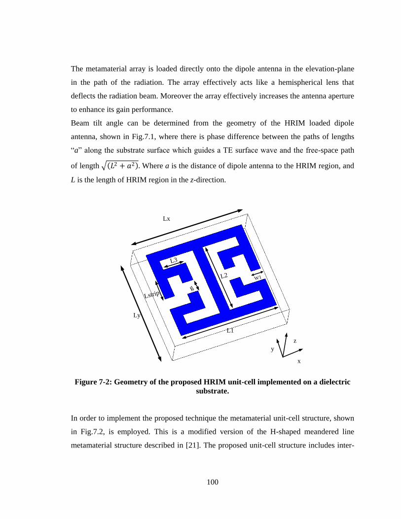
100
The metamaterial array is loaded directly onto the dipole antenna in the elevation-plane
in the path of the radiation. The array effectively acts like a hemispherical lens that
deflects the radiation beam. Moreover the array effectively increases the antenna aperture
to enhance its gain performance.
Beam tilt angle can be determined from the geometry of the HRIM loaded dipole
antenna, shown in Fig.7.1, where there is phase difference between the paths of lengths
“a” along the substrate surface which guides a TE surface wave and the free-space path
of length 𝐿2 + 𝑎2 . Where a is the distance of dipole antenna to the HRIM region, and
L is the length of HRIM region in the z-direction.
x
y
z
Ly
L1
L2
Lstrip
L3
g
W1
Lx
Figure 7-2: Geometry of the proposed HRIM unit-cell implemented on a dielectric
substrate.
In order to implement the proposed technique the metamaterial unit-cell structure, shown
in Fig.7.2, is employed. This is a modified version of the H-shaped meandered line
metamaterial structure described in [21]. The proposed unit-cell structure includes inter-
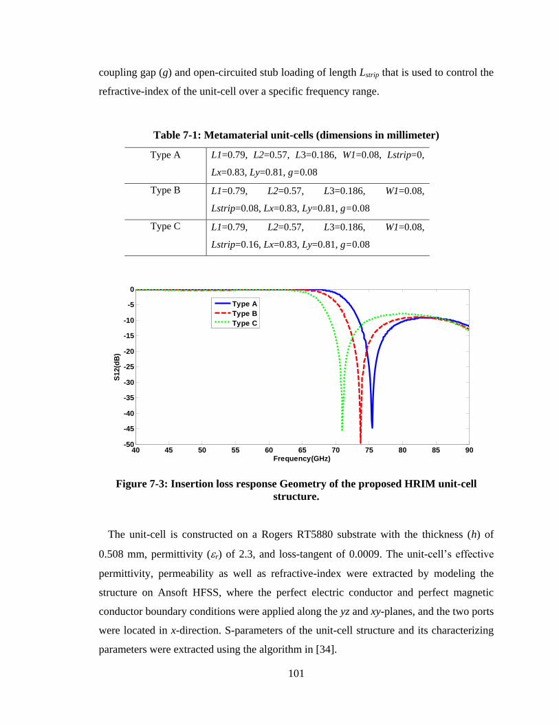
101
coupling gap (g) and open-circuited stub loading of length Lstrip that is used to control the
refractive-index of the unit-cell over a specific frequency range.
Table 7-1: Metamaterial unit-cells (dimensions in millimeter)
Type A L1=0.79, L2=0.57, L3=0.186, W1=0.08, Lstrip=0,
Lx=0.83, Ly=0.81, g=0.08
Type B L1=0.79, L2=0.57, L3=0.186, W1=0.08,
Lstrip=0.08, Lx=0.83, Ly=0.81, g=0.08
Type C L1=0.79, L2=0.57, L3=0.186, W1=0.08,
Lstrip=0.16, Lx=0.83, Ly=0.81, g=0.08
Figure 7-3: Insertion loss response Geometry of the proposed HRIM unit-cell
structure.
The unit-cell is constructed on a Rogers RT5880 substrate with the thickness (h) of
0.508 mm, permittivity (r) of 2.3, and loss-tangent of 0.0009. The unit-cell‟s effective
permittivity, permeability as well as refractive-index were extracted by modeling the
structure on Ansoft HFSS, where the perfect electric conductor and perfect magnetic
conductor boundary conditions were applied along the yz and xy-planes, and the two ports
were located in x-direction. S-parameters of the unit-cell structure and its characterizing
parameters were extracted using the algorithm in [34].
40 45 50 55 60 65 70 75 80 85 90-50
-45
-40
-35
-30
-25
-20
-15
-10
-5
0
Frequency(GHz)
S1
2(d
B)
Type A
Type B
Type C
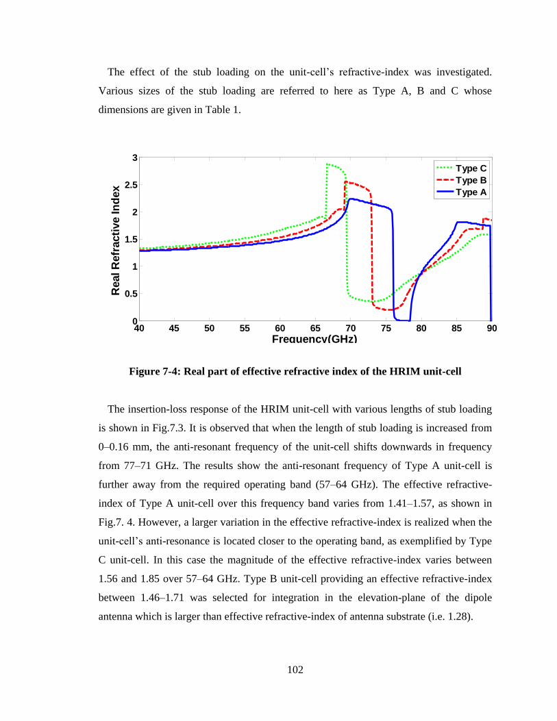
102
The effect of the stub loading on the unit-cell‟s refractive-index was investigated.
Various sizes of the stub loading are referred to here as Type A, B and C whose
dimensions are given in Table 1.
Figure 7-4: Real part of effective refractive index of the HRIM unit-cell
The insertion-loss response of the HRIM unit-cell with various lengths of stub loading
is shown in Fig.7.3. It is observed that when the length of stub loading is increased from
0–0.16 mm, the anti-resonant frequency of the unit-cell shifts downwards in frequency
from 77–71 GHz. The results show the anti-resonant frequency of Type A unit-cell is
further away from the required operating band (57–64 GHz). The effective refractive-
index of Type A unit-cell over this frequency band varies from 1.41–1.57, as shown in
Fig.7. 4. However, a larger variation in the effective refractive-index is realized when the
unit-cell‟s anti-resonance is located closer to the operating band, as exemplified by Type
C unit-cell. In this case the magnitude of the effective refractive-index varies between
1.56 and 1.85 over 57–64 GHz. Type B unit-cell providing an effective refractive-index
between 1.46–1.71 was selected for integration in the elevation-plane of the dipole
antenna which is larger than effective refractive-index of antenna substrate (i.e. 1.28).
40 45 50 55 60 65 70 75 80 85 900
0.5
1
1.5
2
2.5
3
Frequency(GHz)
Real R
efr
acti
ve In
dex
Type C
Type B
Type A
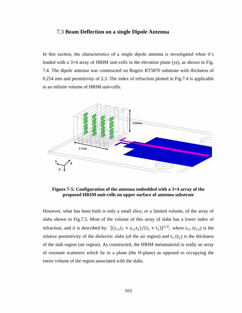
103
7.3 Beam Deflection on a single Dipole Antenna
In this section, the characteristics of a single dipole antenna is investigated when it‟s
loaded with a 3×4 array of HRIM unit-cells in the elevation plane (yz), as shown in Fig.
7.4. The dipole antenna was constructed on Rogers RT5870 substrate with thickness of
0.254 mm and permittivity of 2.3. The index of refraction plotted in Fig.7.4 is applicable
to an infinite volume of HRIM unit-cells.
Figure 7-5: Configuration of the antenna embedded with a 3×4 array of the
proposed HRIM unit-cells on upper surface of antenna substrate
However, what has been built is only a small slice, or a limited volume, of the array of
slabs shown in Fig.7.5. Most of the volume of this array of slabs has a lower index of
refraction, and it is described by: 𝜀𝑟1𝑡1 + 𝜀𝑟2𝑡2 𝑡1 + 𝑡2 1 2 , where 𝜀𝑟1 (𝜀𝑟2) is the
relative permittivity of the dielectric slabs (of the air region) and 𝑡1 (𝑡2) is the thickness
of the slab region (air region). As constructed, the HRIM metamaterial is really an array
of resonant scatterers which lie in a plane (the H-plane) as opposed to occupying the
entire volume of the region associated with the slabs.
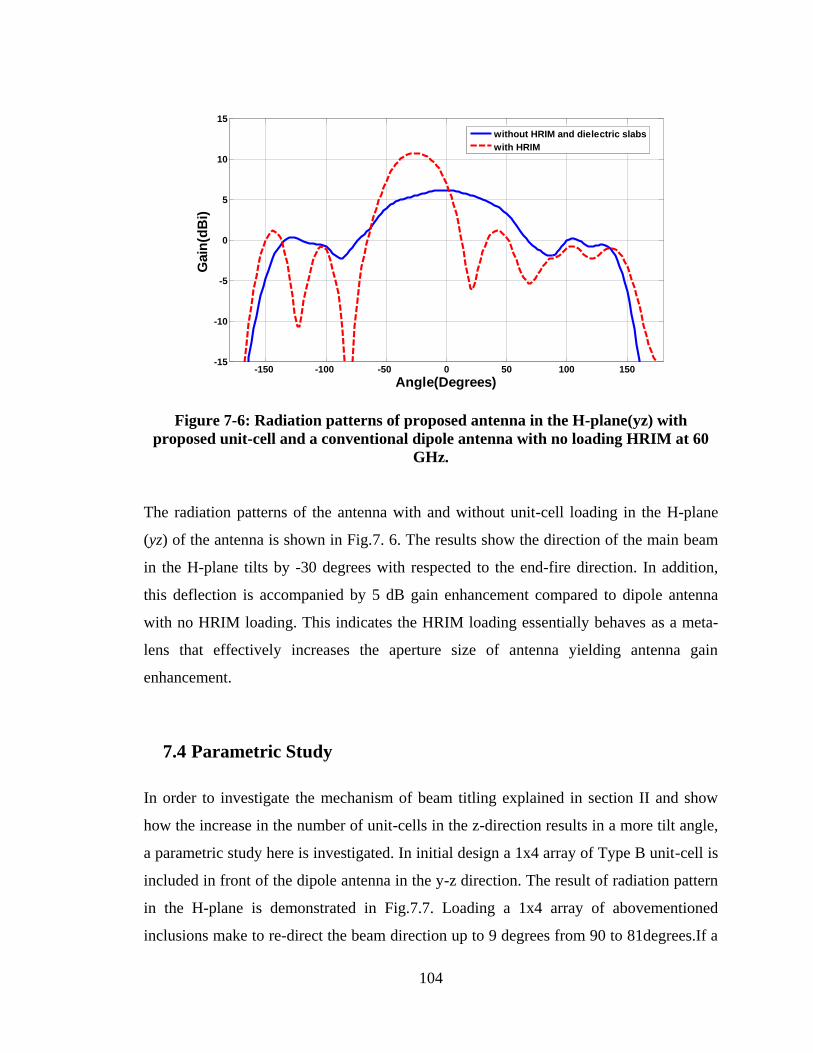
104
Figure 7-6: Radiation patterns of proposed antenna in the H-plane(yz) with
proposed unit-cell and a conventional dipole antenna with no loading HRIM at 60
GHz.
The radiation patterns of the antenna with and without unit-cell loading in the H-plane
(yz) of the antenna is shown in Fig.7. 6. The results show the direction of the main beam
in the H-plane tilts by -30 degrees with respected to the end-fire direction. In addition,
this deflection is accompanied by 5 dB gain enhancement compared to dipole antenna
with no HRIM loading. This indicates the HRIM loading essentially behaves as a meta-
lens that effectively increases the aperture size of antenna yielding antenna gain
enhancement.
7.4 Parametric Study
In order to investigate the mechanism of beam titling explained in section II and show
how the increase in the number of unit-cells in the z-direction results in a more tilt angle,
a parametric study here is investigated. In initial design a 1x4 array of Type B unit-cell is
included in front of the dipole antenna in the y-z direction. The result of radiation pattern
in the H-plane is demonstrated in Fig.7.7. Loading a 1x4 array of abovementioned
inclusions make to re-direct the beam direction up to 9 degrees from 90 to 81degrees.If a
-150 -100 -50 0 50 100 150-15
-10
-5
0
5
10
15
Angle(Degrees)
Gain
(dB
i)
without HRIM and dielectric slabs
with HRIM
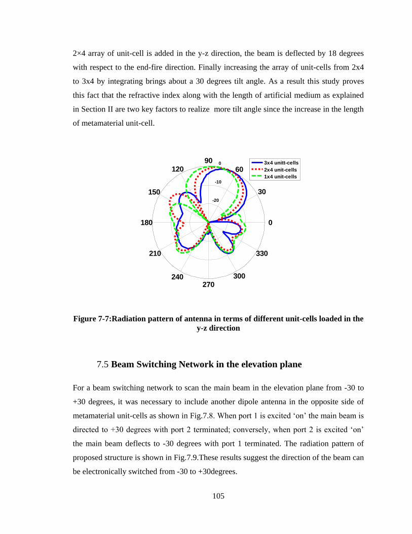
105
2×4 array of unit-cell is added in the y-z direction, the beam is deflected by 18 degrees
with respect to the end-fire direction. Finally increasing the array of unit-cells from 2x4
to 3x4 by integrating brings about a 30 degrees tilt angle. As a result this study proves
this fact that the refractive index along with the length of artificial medium as explained
in Section II are two key factors to realize more tilt angle since the increase in the length
of metamaterial unit-cell.
Figure 7-7:Radiation pattern of antenna in terms of different unit-cells loaded in the
y-z direction
7.5 Beam Switching Network in the elevation plane
For a beam switching network to scan the main beam in the elevation plane from -30 to
+30 degrees, it was necessary to include another dipole antenna in the opposite side of
metamaterial unit-cells as shown in Fig.7.8. When port 1 is excited „on‟ the main beam is
directed to +30 degrees with port 2 terminated; conversely, when port 2 is excited „on‟
the main beam deflects to -30 degrees with port 1 terminated. The radiation pattern of
proposed structure is shown in Fig.7.9.These results suggest the direction of the beam can
be electronically switched from -30 to +30degrees.
-20
-10
0
30
210
60
240
90
270
120
300
150
330
180 0
3x4 unitt-cells
2x4 unit-cells
1x4 unit-cells
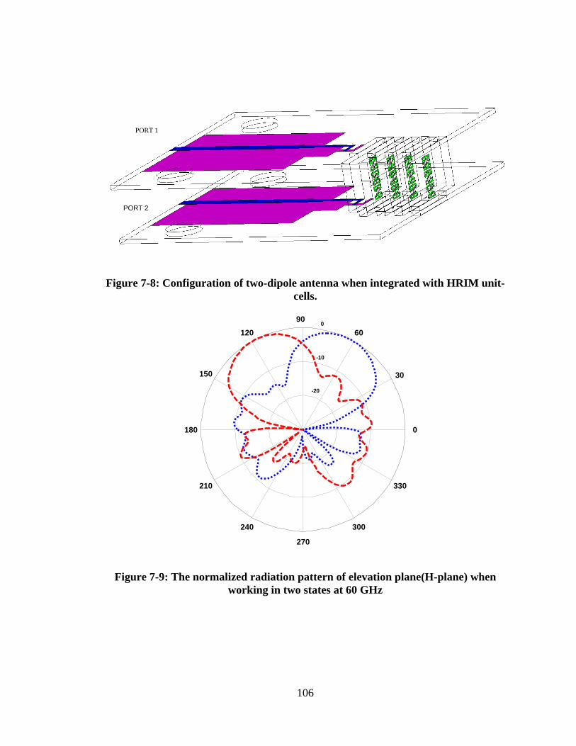
106
PORT 1
PORT 2
Figure 7-8: Configuration of two-dipole antenna when integrated with HRIM unit-
cells.
-20
-10
0
30
210
60
240
90
270
120
300
150
330
180 0
Figure 7-9: The normalized radiation pattern of elevation plane(H-plane) when
working in two states at 60 GHz
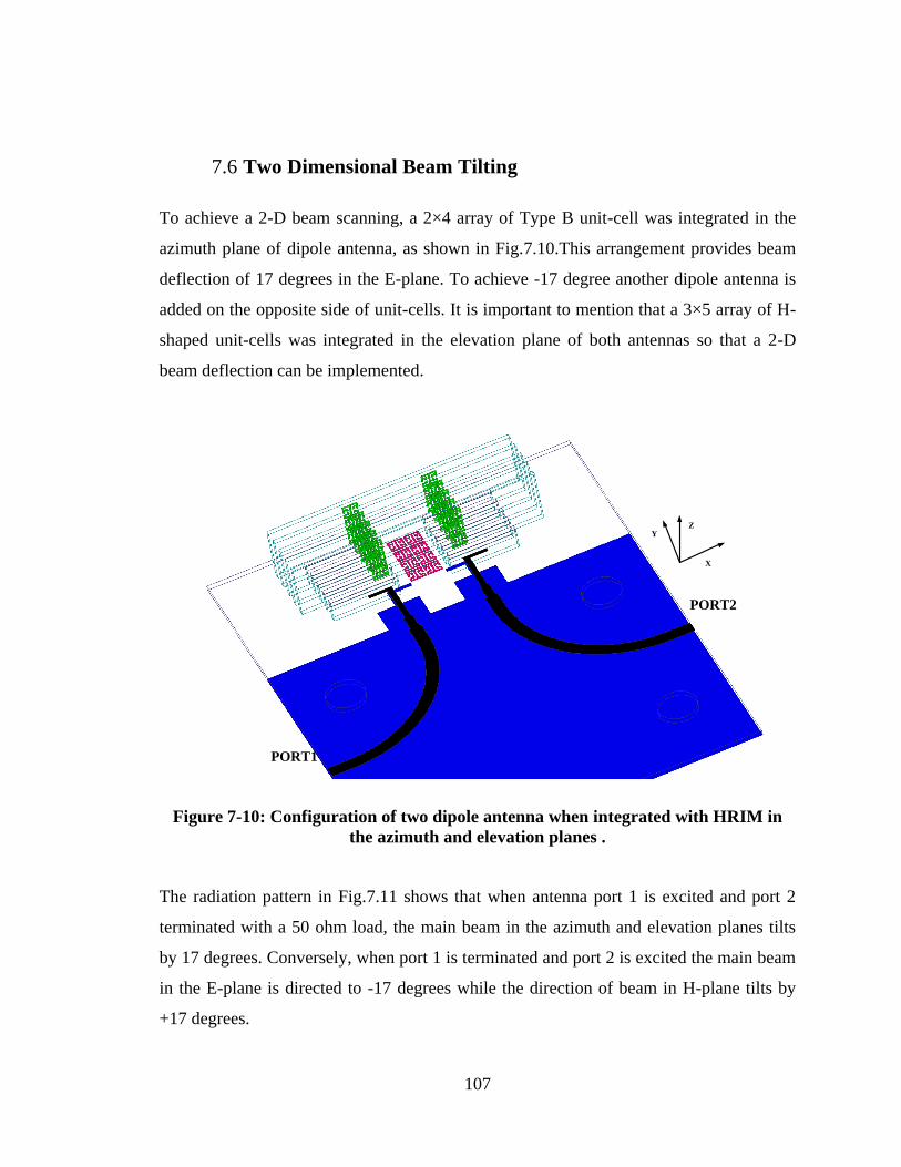
107
7.6 Two Dimensional Beam Tilting
To achieve a 2-D beam scanning, a 2×4 array of Type B unit-cell was integrated in the
azimuth plane of dipole antenna, as shown in Fig.7.10.This arrangement provides beam
deflection of 17 degrees in the E-plane. To achieve -17 degree another dipole antenna is
added on the opposite side of unit-cells. It is important to mention that a 3×5 array of H-
shaped unit-cells was integrated in the elevation plane of both antennas so that a 2-D
beam deflection can be implemented.
X
ZY
PORT1
PORT2
Figure 7-10: Configuration of two dipole antenna when integrated with HRIM in
the azimuth and elevation planes .
The radiation pattern in Fig.7.11 shows that when antenna port 1 is excited and port 2
terminated with a 50 ohm load, the main beam in the azimuth and elevation planes tilts
by 17 degrees. Conversely, when port 1 is terminated and port 2 is excited the main beam
in the E-plane is directed to -17 degrees while the direction of beam in H-plane tilts by
+17 degrees.
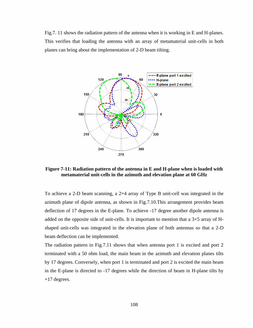
108
Fig.7. 11 shows the radiation pattern of the antenna when it is working in E and H-planes.
This verifies that loading the antenna with an array of metamaterial unit-cells in both
planes can bring about the implementation of 2-D beam tilting.
Figure 7-11: Radiation pattern of the antenna in E and H-plane when is loaded with
metamaterial unit-cells in the azimuth and elevation plane at 60 GHz
To achieve a 2-D beam scanning, a 2×4 array of Type B unit-cell was integrated in the
azimuth plane of dipole antenna, as shown in Fig.7.10.This arrangement provides beam
deflection of 17 degrees in the E-plane. To achieve -17 degree another dipole antenna is
added on the opposite side of unit-cells. It is important to mention that a 3×5 array of H-
shaped unit-cells was integrated in the elevation plane of both antennas so that a 2-D
beam deflection can be implemented.
The radiation pattern in Fig.7.11 shows that when antenna port 1 is excited and port 2
terminated with a 50 ohm load, the main beam in the azimuth and elevation planes tilts
by 17 degrees. Conversely, when port 1 is terminated and port 2 is excited the main beam
in the E-plane is directed to -17 degrees while the direction of beam in H-plane tilts by
+17 degrees.
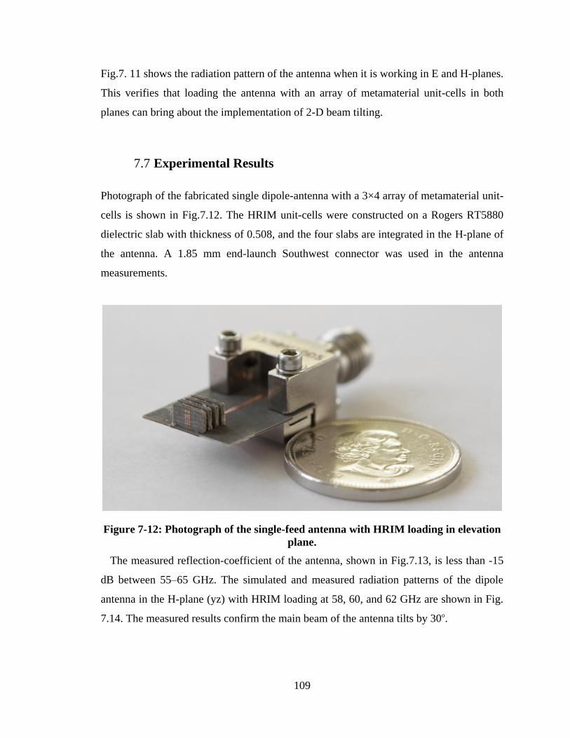
109
Fig.7. 11 shows the radiation pattern of the antenna when it is working in E and H-planes.
This verifies that loading the antenna with an array of metamaterial unit-cells in both
planes can bring about the implementation of 2-D beam tilting.
7.7 Experimental Results
Photograph of the fabricated single dipole-antenna with a 3×4 array of metamaterial unit-
cells is shown in Fig.7.12. The HRIM unit-cells were constructed on a Rogers RT5880
dielectric slab with thickness of 0.508, and the four slabs are integrated in the H-plane of
the antenna. A 1.85 mm end-launch Southwest connector was used in the antenna
measurements.
Figure 7-12: Photograph of the single-feed antenna with HRIM loading in elevation
plane.
The measured reflection-coefficient of the antenna, shown in Fig.7.13, is less than -15
dB between 55–65 GHz. The simulated and measured radiation patterns of the dipole
antenna in the H-plane (yz) with HRIM loading at 58, 60, and 62 GHz are shown in Fig.
7.14. The measured results confirm the main beam of the antenna tilts by 30o.
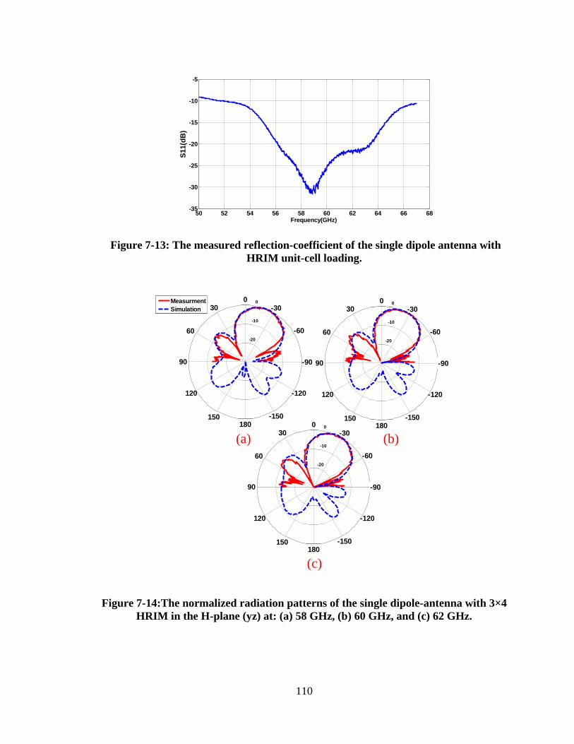
110
Figure 7-13: The measured reflection-coefficient of the single dipole antenna with
HRIM unit-cell loading.
-20
-10
0
-60
120
-30
150
0
180
30
-150
60
-120
90 -90
Measurment
Simulation
-20
-10
0
-60
120
-30
150
0
180
30
-150
60
-120
90 -90
-20
-10
0
-60
120
-30
150
0
180
30
-150
60
-120
90 -90
(a) (b)
(c)
Figure 7-14:The normalized radiation patterns of the single dipole-antenna with 3×4
HRIM in the H-plane (yz) at: (a) 58 GHz, (b) 60 GHz, and (c) 62 GHz.
50 52 54 56 58 60 62 64 66 68-35
-30
-25
-20
-15
-10
-5
Frequency(GHz)
S11(d
B)
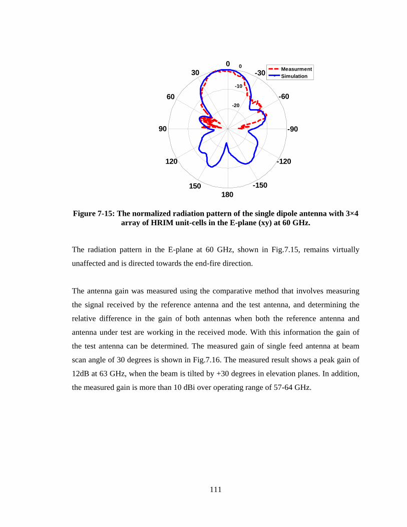
111
Figure 7-15: The normalized radiation pattern of the single dipole antenna with 3×4
array of HRIM unit-cells in the E-plane (xy) at 60 GHz.
The radiation pattern in the E-plane at 60 GHz, shown in Fig.7.15, remains virtually
unaffected and is directed towards the end-fire direction.
The antenna gain was measured using the comparative method that involves measuring
the signal received by the reference antenna and the test antenna, and determining the
relative difference in the gain of both antennas when both the reference antenna and
antenna under test are working in the received mode. With this information the gain of
the test antenna can be determined. The measured gain of single feed antenna at beam
scan angle of 30 degrees is shown in Fig.7.16. The measured result shows a peak gain of
12dB at 63 GHz, when the beam is tilted by +30 degrees in elevation planes. In addition,
the measured gain is more than 10 dBi over operating range of 57-64 GHz.
-20
-10
0
-60
120
-30
150
0
180
30
-150
60
-120
90 -90
Measurment
Simulation
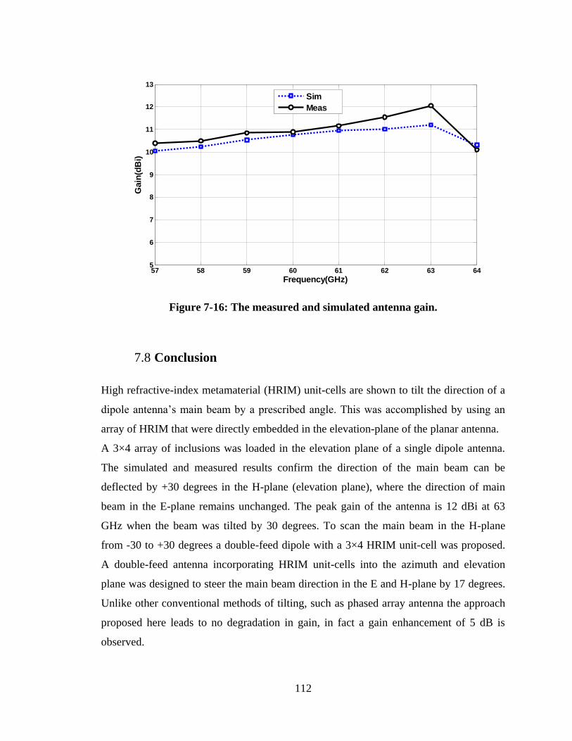
112
Figure 7-16: The measured and simulated antenna gain.
7.8 Conclusion
High refractive-index metamaterial (HRIM) unit-cells are shown to tilt the direction of a
dipole antenna‟s main beam by a prescribed angle. This was accomplished by using an
array of HRIM that were directly embedded in the elevation-plane of the planar antenna.
A 3×4 array of inclusions was loaded in the elevation plane of a single dipole antenna.
The simulated and measured results confirm the direction of the main beam can be
deflected by +30 degrees in the H-plane (elevation plane), where the direction of main
beam in the E-plane remains unchanged. The peak gain of the antenna is 12 dBi at 63
GHz when the beam was tilted by 30 degrees. To scan the main beam in the H-plane
from -30 to +30 degrees a double-feed dipole with a 3×4 HRIM unit-cell was proposed.
A double-feed antenna incorporating HRIM unit-cells into the azimuth and elevation
plane was designed to steer the main beam direction in the E and H-plane by 17 degrees.
Unlike other conventional methods of tilting, such as phased array antenna the approach
proposed here leads to no degradation in gain, in fact a gain enhancement of 5 dB is
observed.
57 58 59 60 61 62 63 645
6
7
8
9
10
11
12
13
Frequency(GHz)
Gain
(dB
i)
Sim
Meas
113
Chapter 8 ONE AND TWO DIMENSIONAL BEAM SCANNING
ANTENNA FOR MILLIMETER-WAVE MIMO APPLICATIONS
8.1 Introduction
60 GHz unlicensed band is attracting significant attention as it offers a huge frequency
band (57–64 GHz) and signals incur large loss due to atmospheric absorption. Other
characteristics that make this frequency band attractive are lower interference and greater
frequency reuse. The 60 GHz frequency band promises data rates greater than 1 Gb/s
over a short distance and highly compact and miniaturized systems. Although the major
issue associated with working at 60 GHz is the large path-loss attenuation encountered,
this can be compensated by using high-gain antennas. Since the antenna gain is inversely
proportional to beamwidth, therefore high-gain antennas are associated with narrow
beamwidth. This property can effectively be used to mitigate interference and multipath
effects. However, such antennas make the beam alignment challenging where the
location of transmitter or receiver is not fixed [62].
The antenna radiation beam can be steered using various techniques such as integrated
lens antenna at millimeter-waves [73-75]; however, this approach results in a bulky
antenna. The 1D and 2D beam-scanning at 30 GHz reported in [66] uses a 2×2 substrate
integrated waveguide (SIW) antenna array implemented with a combination of couplers
and phase shifters to provide a gain of about 8.5 dBi. The 8-port hybrid coupler employed
results in a very large antenna structure (20×16.766×0.07).
The authors in [76] have utilized the integrated waveguide phase shifter to achieve 2D
beam-scanning by using a 2×2 microstrip ring antenna array. This technique enables the
main beam to be deflected by 20 degrees in both planes. The beamforming structure was
implemented on a multilayer substrate which makes its construction complicated. This
antenna provides a gain and radiation efficiency of 8.3 dBi and 70%, respectively, when
the beam is scanned. The dimensions of structure are 2.86×2.86×0.22. Adaptive
114
antennas or phased array antennas is another approach reported in [77],[78] to re-direct
the beam direction in a desired angle. The above techniques require using many antenna
elements, which introduces large losses and lead to costly systems.
Metamaterials have received considerable attention for applications in beamforming
networks. For instance, metamaterial based phase shifters using a conventional negative
reflection-index phase shifter which is fed by a 3-element leaky wave CPW-CTS antenna
array provides a scanning angle of 66 degrees in the E-plane with maximum gain of 11
dBi at 2.4 GHz [79]. In [4], an active metamaterial with tunable refractive-index is shown
to scan the main beam of patch antenna from 0 to 30 degrees where a gain of 5 dB is
obtained at 30 degrees. However, this antenna produces large side-lobe levels, and the
structure is physically large. In order to obtain a low-profile structure, the authors in [21]
introduced a high refractive-index metamaterial unit-cell integrated in the azimuth plane
of a printed bow-tie antenna arrays to achieve 17 degrees beam tilt angle with maximum
peak gain of 9.45 dB. However, the beam deflection is fixed and the maximum scan
angle is limited to 17 degrees.
This chapter presents results on 1D and 2D beam scanning technique using a mu ()
near-zero (MNZ) metamaterial unit-cell configuration using end-fire antenna for
application in millimeter-wave MIMO systems operating over 57–64 GHz. End-fire
antenna was selected for this investigation as it facilitates beam-switching compared to
broadside radiating antennas, especially at millimeter-wave frequencies. To the authors‟
knowledge, this is the first time that MNZ unit-cells have been used for 2D beam-
scanning MIMO antenna at 60 GHz. The proposed structure is adaptable for mechanical
scanning in both planes.
115
8.2 Mechanism of Beam scanning
It has been demonstrated in [65] that by integrating a dielectric lens in front of the
antenna, which is offset from the center of the antenna, cause radiated EM waves to be
refracted in a pre-defined angle. This phenomenon is due EM waves traversing in two
media of different refractive indices as predicted by Snell‟s law. This concept has been
applied here however the dielectric lens has been substituted for a metamaterial lens. The
proposed metamaterial lens is used in the azimuth and elevation planes of the dipole
antenna in order to refract the direction of the main beam in both planes. Unlike the
dielectric lens [80]-[81] the incorporation of the metamaterial lens provides 2D beam
scanning and facilitates the realization of a miniaturized structure.
Anisotropic metamaterial unit-cells are integrated onto the dipole antenna, as illustrated
in Fig.8.1, where the unit-cells essentially act as a metamaterial lens. In the analysis the
dipole antenna is regarded as a quasi TE source that emits EM rays. Each ray emanating
from the source has an effective path length to the antenna‟s radiating aperture, and
therefore different phase shift angles.
It is evident from Fig.8.1 that the position of the dipole antenna determines the scan
angle in both azimuth and elevation planes since the movement of antenna changes the
effective path length of each ray over its radiating aperture. Better understanding of the
mechanism of this phenomenon can be obtained by calculating the array factor as
described in [57]. The dipole antenna is considered to be a quasi TE source and the
polarization of the E-field is along the azimuth plane. The dispersion equation for TE
polarization to calculate the wave vector inside the metamaterial region is [14]:
𝛽𝑧
2
𝜇𝑇+
𝛽𝑇2
𝜇𝑧= 𝑘𝑑𝑖𝑒
2𝜀𝑇 (1)
Where the permeability along the optical axis is denoted by 𝜇𝑧 , which has a different
value to the permeability along the transverse axes (𝜇𝑥 = 𝜇𝑦 = 𝜇𝑇).
Transfer function of the configuration in Fig.8.1 is obtained by calculating the
transmission and multiple reflection-coefficients on the top and back surface of
metamaterial region when the EM wave is obliquely incident on it. Transfer function is
given by:
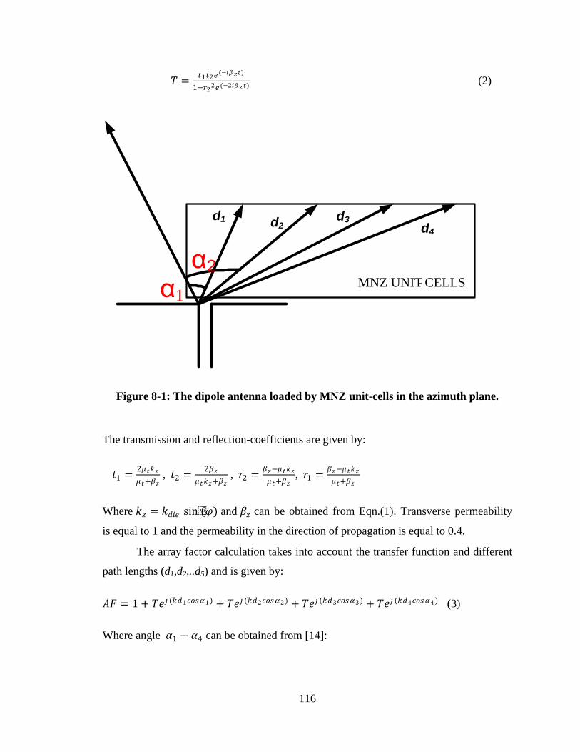
116
𝑇 =𝑡1𝑡2𝑒 (−𝑖𝛽𝑧𝑡)
1−𝑟22𝑒 (−2𝑖𝛽𝑧𝑡) (2)
MNZ UNIT- CELLS
d1
α1
α2
d2d3
d4
Figure 8-1: The dipole antenna loaded by MNZ unit-cells in the azimuth plane.
The transmission and reflection-coefficients are given by:
𝑡1 =2𝜇 𝑡𝑘𝑧
𝜇 𝑡+𝛽𝑧 , 𝑡2 =
2𝛽𝑧
𝜇 𝑡𝑘𝑧+𝛽𝑧 , 𝑟2 =
𝛽𝑧−𝜇 𝑡𝑘𝑧
𝜇 𝑡+𝛽𝑧, 𝑟1 =
𝛽𝑧−𝜇 𝑡𝑘𝑧
𝜇 𝑡+𝛽𝑧
Where 𝑘𝑧 = 𝑘𝑑𝑖𝑒 sin(𝜑) and 𝛽𝑧 can be obtained from Eqn.(1). Transverse permeability
is equal to 1 and the permeability in the direction of propagation is equal to 0.4.
The array factor calculation takes into account the transfer function and different
path lengths (d1,d2,..d5) and is given by:
𝐴𝐹 = 1 + 𝑇𝑒𝑗 (𝑘𝑑1𝑐𝑜𝑠𝛼1) + 𝑇𝑒𝑗 (𝑘𝑑2𝑐𝑜𝑠𝛼2) + 𝑇𝑒𝑗 (𝑘𝑑3𝑐𝑜𝑠𝛼3) + 𝑇𝑒𝑗 (𝑘𝑑4𝑐𝑜𝑠𝛼4) (3)
Where angle 𝛼1 − 𝛼4 can be obtained from [14]:
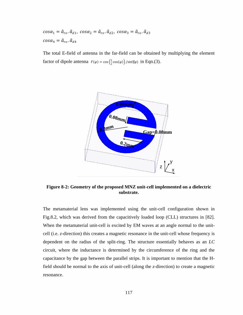
117
𝑐𝑜𝑠𝛼1 = 𝑎 𝑟𝑜 . 𝑎 𝑑1, 𝑐𝑜𝑠𝛼2 = 𝑎 𝑟𝑜 . 𝑎 𝑑2, 𝑐𝑜𝑠𝛼3 = 𝑎 𝑟𝑜 . 𝑎 𝑑3
𝑐𝑜𝑠𝛼4 = 𝑎 𝑟𝑜 . 𝑎 𝑑4
The total E-field of antenna in the far-field can be obtained by multiplying the element
factor of dipole antenna 𝐹 𝜑 = cos 𝜋
2cos 𝜑 /sin(𝜑) in Eqn.(3).
0.08mm
0.08mm
Gap=0.08mm
0.2mm
0.3mm
x
yz
Figure 8-2: Geometry of the proposed MNZ unit-cell implemented on a dielectric
substrate.
The metamaterial lens was implemented using the unit-cell configuration shown in
Fig.8.2, which was derived from the capacitively loaded loop (CLL) structures in [82].
When the metamaterial unit-cell is excited by EM waves at an angle normal to the unit-
cell (i.e. z-direction) this creates a magnetic resonance in the unit-cell whose frequency is
dependent on the radius of the split-ring. The structure essentially behaves as an LC
circuit, where the inductance is determined by the circumference of the ring and the
capacitance by the gap between the parallel strips. It is important to mention that the H-
field should be normal to the axis of unit-cell (along the z-direction) to create a magnetic
resonance.
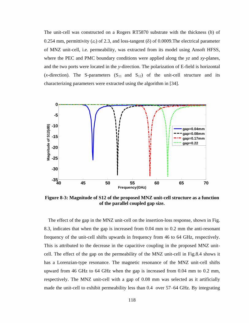
118
The unit-cell was constructed on a Rogers RT5870 substrate with the thickness (h) of
0.254 mm, permittivity (r) of 2.3, and loss-tangent () of 0.0009.The electrical parameter
of MNZ unit-cell, i.e. permeability, was extracted from its model using Ansoft HFSS,
where the PEC and PMC boundary conditions were applied along the yz and xy-planes,
and the two ports were located in the y-direction. The polarization of E-field is horizontal
(x-direction). The S-parameters (S11 and S12) of the unit-cell structure and its
characterizing parameters were extracted using the algorithm in [34].
Figure 8-3: Magnitude of S12 of the proposed MNZ unit-cell structure as a function
of the parallel coupled gap size.
The effect of the gap in the MNZ unit-cell on the insertion-loss response, shown in Fig.
8.3, indicates that when the gap is increased from 0.04 mm to 0.2 mm the anti-resonant
frequency of the unit-cell shifts upwards in frequency from 46 to 64 GHz, respectively.
This is attributed to the decrease in the capacitive coupling in the proposed MNZ unit-
cell. The effect of the gap on the permeability of the MNZ unit-cell in Fig.8.4 shows it
has a Lorenzian-type resonance. The magnetic resonance of the MNZ unit-cell shifts
upward from 46 GHz to 64 GHz when the gap is increased from 0.04 mm to 0.2 mm,
respectively. The MNZ unit-cell with a gap of 0.08 mm was selected as it artificially
made the unit-cell to exhibit permeability less than 0.4 over 57–64 GHz. By integrating
40 45 50 55 60 65 70-35
-30
-25
-20
-15
-10
-5
0
Frequency(GHz)
Mag
nit
ud
e o
f S
12(d
B)
gap=0.04mm
gap=0.08mm
gap=0.17mm
gap=0.22
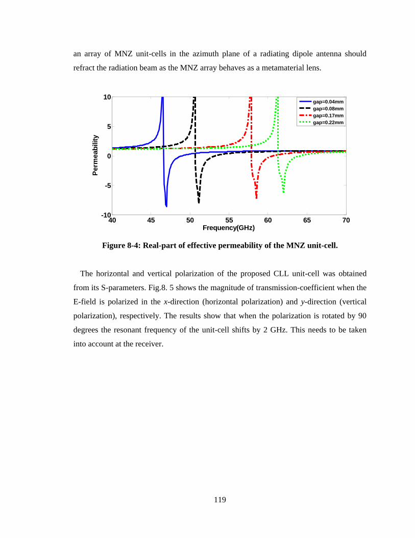
119
an array of MNZ unit-cells in the azimuth plane of a radiating dipole antenna should
refract the radiation beam as the MNZ array behaves as a metamaterial lens.
Figure 8-4: Real-part of effective permeability of the MNZ unit-cell.
The horizontal and vertical polarization of the proposed CLL unit-cell was obtained
from its S-parameters. Fig.8. 5 shows the magnitude of transmission-coefficient when the
E-field is polarized in the x-direction (horizontal polarization) and y-direction (vertical
polarization), respectively. The results show that when the polarization is rotated by 90
degrees the resonant frequency of the unit-cell shifts by 2 GHz. This needs to be taken
into account at the receiver.
40 45 50 55 60 65 70-10
-5
0
5
10
Frequency(GHz)
Perm
eab
ilit
y
gap=0.04mm
gap=0.08mm
gap=0.17mm
gap=0.22mm
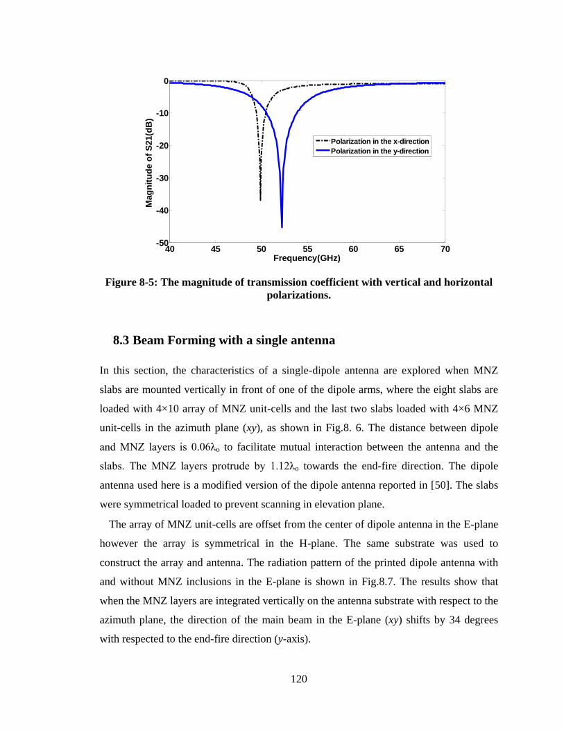
120
Figure 8-5: The magnitude of transmission coefficient with vertical and horizontal
polarizations.
8.3 Beam Forming with a single antenna
In this section, the characteristics of a single-dipole antenna are explored when MNZ
slabs are mounted vertically in front of one of the dipole arms, where the eight slabs are
loaded with 4×10 array of MNZ unit-cells and the last two slabs loaded with 4×6 MNZ
unit-cells in the azimuth plane (xy), as shown in Fig.8. 6. The distance between dipole
and MNZ layers is 0.06λo to facilitate mutual interaction between the antenna and the
slabs. The MNZ layers protrude by 1.12λo towards the end-fire direction. The dipole
antenna used here is a modified version of the dipole antenna reported in [50]. The slabs
were symmetrical loaded to prevent scanning in elevation plane.
The array of MNZ unit-cells are offset from the center of dipole antenna in the E-plane
however the array is symmetrical in the H-plane. The same substrate was used to
construct the array and antenna. The radiation pattern of the printed dipole antenna with
and without MNZ inclusions in the E-plane is shown in Fig.8.7. The results show that
when the MNZ layers are integrated vertically on the antenna substrate with respect to the
azimuth plane, the direction of the main beam in the E-plane (xy) shifts by 34 degrees
with respected to the end-fire direction (y-axis).
40 45 50 55 60 65 70-50
-40
-30
-20
-10
0
Frequency(GHz)
Mag
nit
ud
e o
f S
21(d
B)
Polarization in the x-direction
Polarization in the y-direction
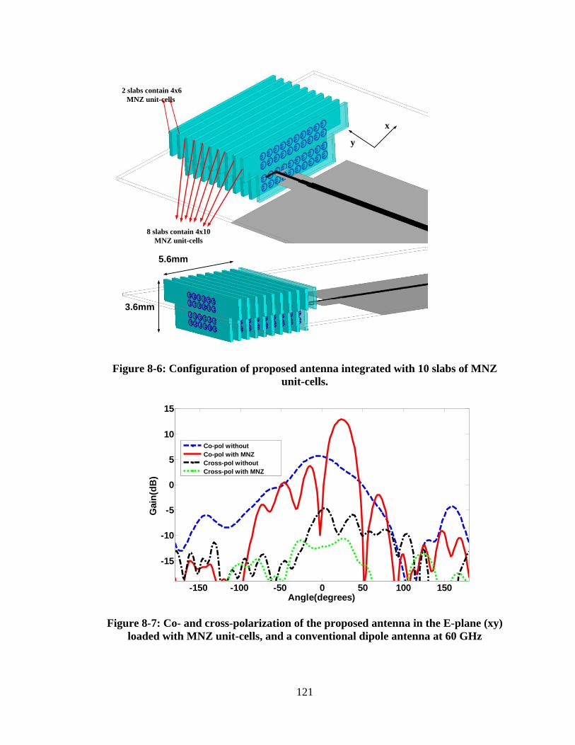
121
x
y
8 slabs contain 4x10
MNZ unit-cells
2 slabs contain 4x6
MNZ unit-cells
5.6mm
3.6mm
Figure 8-6: Configuration of proposed antenna integrated with 10 slabs of MNZ
unit-cells.
Figure 8-7: Co- and cross-polarization of the proposed antenna in the E-plane (xy)
loaded with MNZ unit-cells, and a conventional dipole antenna at 60 GHz
-150 -100 -50 0 50 100 150
-15
-10
-5
0
5
10
15
Angle(degrees)
Gain
(dB
)
Co-pol without
Co-pol with MNZ
Cross-pol without
Cross-pol with MNZ
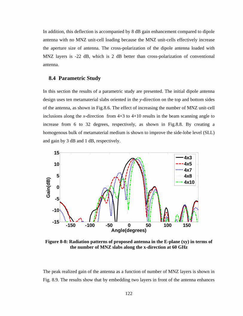
122
In addition, this deflection is accompanied by 8 dB gain enhancement compared to dipole
antenna with no MNZ unit-cell loading because the MNZ unit-cells effectively increase
the aperture size of antenna. The cross-polarization of the dipole antenna loaded with
MNZ layers is -22 dB, which is 2 dB better than cross-polarization of conventional
antenna.
8.4 Parametric Study
In this section the results of a parametric study are presented. The initial dipole antenna
design uses ten metamaterial slabs oriented in the y-direction on the top and bottom sides
of the antenna, as shown in Fig.8.6. The effect of increasing the number of MNZ unit-cell
inclusions along the x-direction from 4×3 to 4×10 results in the beam scanning angle to
increase from 6 to 32 degrees, respectively, as shown in Fig.8.8. By creating a
homogenous bulk of metamaterial medium is shown to improve the side-lobe level (SLL)
and gain by 3 dB and 1 dB, respectively.
Figure 8-8: Radiation patterns of proposed antenna in the E-plane (xy) in terms of
the number of MNZ slabs along the x-direction at 60 GHz
The peak realized gain of the antenna as a function of number of MNZ layers is shown in
Fig. 8.9. The results show that by embedding two layers in front of the antenna enhances
-150 -100 -50 0 50 100 150-15
-10
-5
0
5
10
15
Angle(degrees)
Gain
(dB
)
4x3
4x5
4x7
4x8
4x10
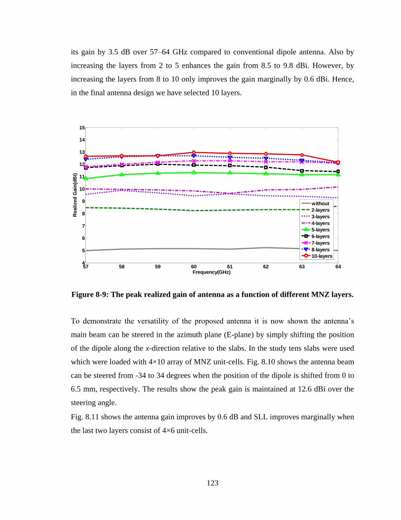
123
its gain by 3.5 dB over 57–64 GHz compared to conventional dipole antenna. Also by
increasing the layers from 2 to 5 enhances the gain from 8.5 to 9.8 dBi. However, by
increasing the layers from 8 to 10 only improves the gain marginally by 0.6 dBi. Hence,
in the final antenna design we have selected 10 layers.
Figure 8-9: The peak realized gain of antenna as a function of different MNZ layers.
To demonstrate the versatility of the proposed antenna it is now shown the antenna‟s
main beam can be steered in the azimuth plane (E-plane) by simply shifting the position
of the dipole along the x-direction relative to the slabs. In the study tens slabs were used
which were loaded with 4×10 array of MNZ unit-cells. Fig. 8.10 shows the antenna beam
can be steered from -34 to 34 degrees when the position of the dipole is shifted from 0 to
6.5 mm, respectively. The results show the peak gain is maintained at 12.6 dBi over the
steering angle.
Fig. 8.11 shows the antenna gain improves by 0.6 dB and SLL improves marginally when
the last two layers consist of 4×6 unit-cells.
57 58 59 60 61 62 63 644
5
6
7
8
9
10
11
12
13
14
15
Frequency(GHz)
Realized
Gain
(dB
i)
without
2-layers
3-layers
4-layers
5-layers
6-layers
7-layers
8-layers
10-layers
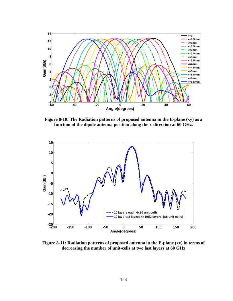
124
Figure 8-10: The Radiation patterns of proposed antenna in the E-plane (xy) as a
function of the dipole antenna position along the x-direction at 60 GHz.
Figure 8-11: Radiation patterns of proposed antenna in the E-plane (xy) in terms of
decreasing the number of unit-cells at two last layers at 60 GHz
-60 -40 -20 0 20 40 60-4
-2
0
2
4
6
8
10
12
14
Angle(degrees)
Gain
(dB
i)
x=0
x=0.5mm
x=1mm
x=1.5mm
x=2mm
x=2.5mm
x=3mm
x=3.5mm
x=4mm
x=4.5mm
x=5mm
x=5.5mm
x=6mm
x=6.5mm
-200 -150 -100 -50 0 50 100 150 200-25
-20
-15
-10
-5
0
5
10
15
Angle(degrees)
Gain
(dB
i)
10 layers each 4x10 unit-cells
10 layers(8 layers 4x10)(2 layers 4x6 unit-cells)
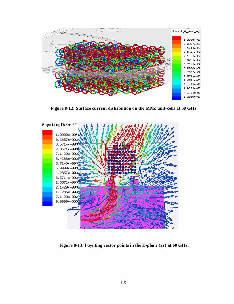
125
Figure 8-12: Surface current distribution on the MNZ unit-cells at 60 GHz.
Figure 8-13: Poynting vector points in the E-plane (xy) at 60 GHz.
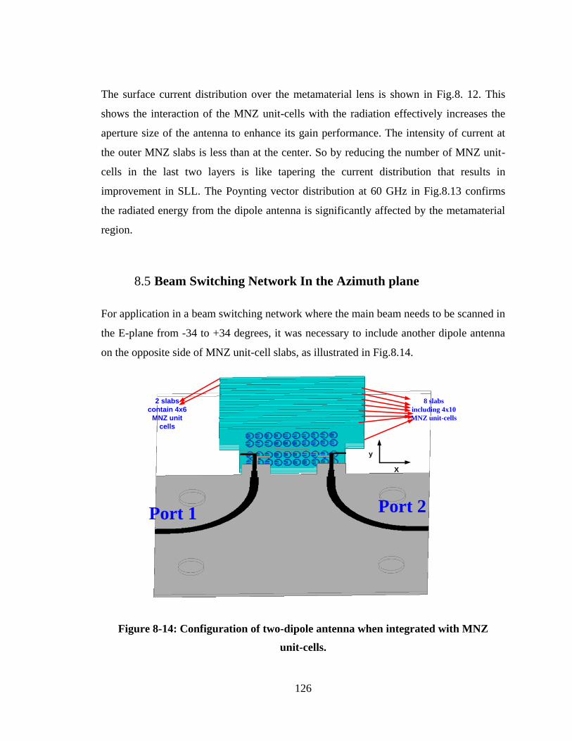
126
The surface current distribution over the metamaterial lens is shown in Fig.8. 12. This
shows the interaction of the MNZ unit-cells with the radiation effectively increases the
aperture size of the antenna to enhance its gain performance. The intensity of current at
the outer MNZ slabs is less than at the center. So by reducing the number of MNZ unit-
cells in the last two layers is like tapering the current distribution that results in
improvement in SLL. The Poynting vector distribution at 60 GHz in Fig.8.13 confirms
the radiated energy from the dipole antenna is significantly affected by the metamaterial
region.
8.5 Beam Switching Network In the Azimuth plane
For application in a beam switching network where the main beam needs to be scanned in
the E-plane from -34 to +34 degrees, it was necessary to include another dipole antenna
on the opposite side of MNZ unit-cell slabs, as illustrated in Fig.8.14.
Port 1 Port 2
8 slabs
including 4x10
MNZ unit-cells
2 slabs
contain 4x6
MNZ unit
cells
X
y
Figure 8-14: Configuration of two-dipole antenna when integrated with MNZ
unit-cells.
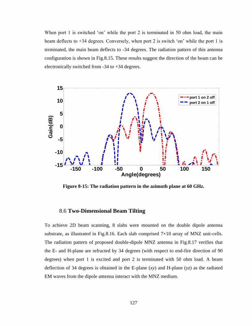
127
When port 1 is switched „on‟ while the port 2 is terminated in 50 ohm load, the main
beam deflects to +34 degrees. Conversely, when port 2 is switch „on‟ while the port 1 is
terminated, the main beam deflects to -34 degrees. The radiation pattern of this antenna
configuration is shown in Fig.8.15. These results suggest the direction of the beam can be
electronically switched from -34 to +34 degrees.
Figure 8-15: The radiation pattern in the azimuth plane at 60 GHz.
8.6 Two-Dimensional Beam Tilting
To achieve 2D beam scanning, 8 slabs were mounted on the double dipole antenna
substrate, as illustrated in Fig.8.16. Each slab comprised 7×10 array of MNZ unit-cells.
The radiation pattern of proposed double-dipole MNZ antenna in Fig.8.17 verifies that
the E- and H-plane are refracted by 34 degrees (with respect to end-fire direction of 90
degrees) when port 1 is excited and port 2 is terminated with 50 ohm load. A beam
deflection of 34 degrees is obtained in the E-plane (xy) and H-plane (yz) as the radiated
EM waves from the dipole antenna interact with the MNZ medium.
-150 -100 -50 0 50 100 150-15
-10
-5
0
5
10
15
Angle(degrees)
Gain
(dB
)
port 1 on 2 off
port 2 on 1 off
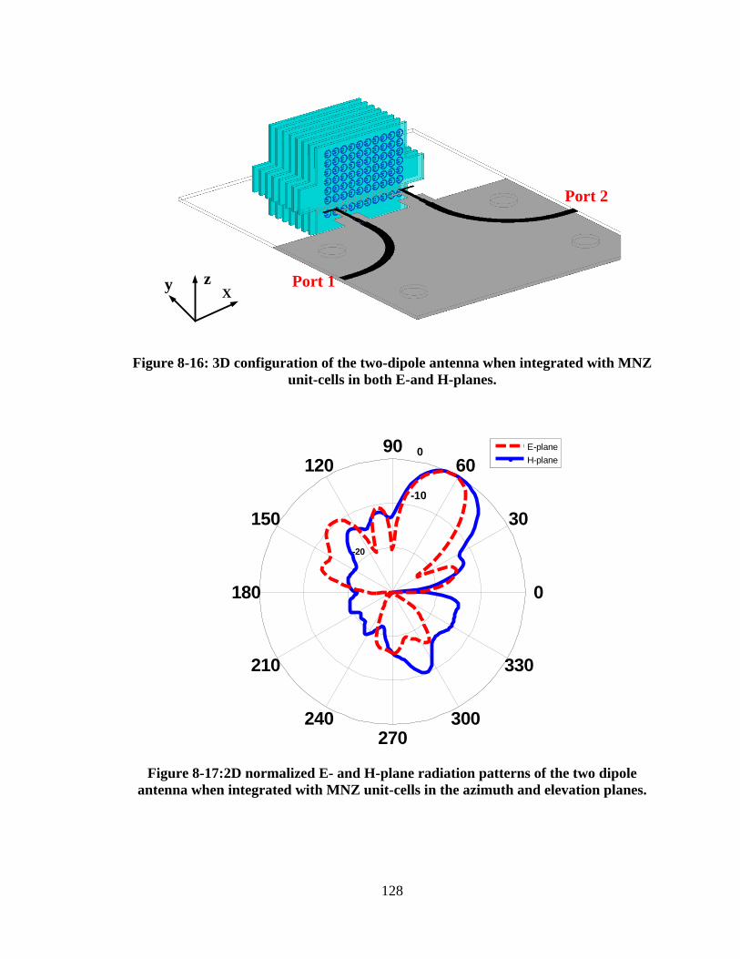
128
Xzy Port 1
Port 2
Figure 8-16: 3D configuration of the two-dipole antenna when integrated with MNZ
unit-cells in both E-and H-planes.
Figure 8-17:2D normalized E- and H-plane radiation patterns of the two dipole
antenna when integrated with MNZ unit-cells in the azimuth and elevation planes.
-20
-10
0
30
210
60
240
90
270
120
300
150
330
180 0
E-plane
H-plane
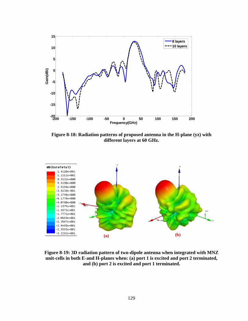
129
Figure 8-18: Radiation patterns of proposed antenna in the H-plane (yz) with
different layers at 60 GHz.
(a) (b)
Figure 8-19: 3D radiation pattern of two-dipole antenna when integrated with MNZ
unit-cells in both E-and H-planes when: (a) port 1 is excited and port 2 terminated,
and (b) port 2 is excited and port 1 terminated.
-200 -150 -100 -50 0 50 100 150 200-20
-15
-10
-5
0
5
10
15
Frequency(GHz)
Gain
(dB
i)
8 layers
10 layers
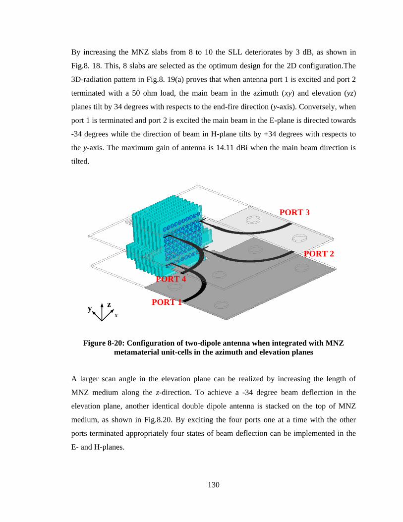
130
By increasing the MNZ slabs from 8 to 10 the SLL deteriorates by 3 dB, as shown in
Fig.8. 18. This, 8 slabs are selected as the optimum design for the 2D configuration.The
3D-radiation pattern in Fig.8. 19(a) proves that when antenna port 1 is excited and port 2
terminated with a 50 ohm load, the main beam in the azimuth (xy) and elevation (yz)
planes tilt by 34 degrees with respects to the end-fire direction (y-axis). Conversely, when
port 1 is terminated and port 2 is excited the main beam in the E-plane is directed towards
-34 degrees while the direction of beam in H-plane tilts by +34 degrees with respects to
the y-axis. The maximum gain of antenna is 14.11 dBi when the main beam direction is
tilted.
PORT 1
PORT 2
PORT 4
PORT 3
X
zy
Figure 8-20: Configuration of two-dipole antenna when integrated with MNZ
metamaterial unit-cells in the azimuth and elevation planes
A larger scan angle in the elevation plane can be realized by increasing the length of
MNZ medium along the z-direction. To achieve a -34 degree beam deflection in the
elevation plane, another identical double dipole antenna is stacked on the top of MNZ
medium, as shown in Fig.8.20. By exciting the four ports one at a time with the other
ports terminated appropriately four states of beam deflection can be implemented in the
E- and H-planes.
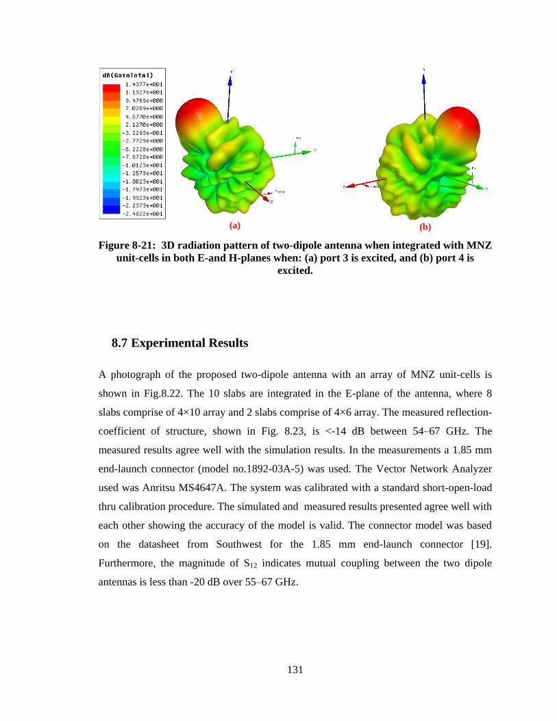
131
(a) (b)
Figure 8-21: 3D radiation pattern of two-dipole antenna when integrated with MNZ
unit-cells in both E-and H-planes when: (a) port 3 is excited, and (b) port 4 is
excited.
8.7 Experimental Results
A photograph of the proposed two-dipole antenna with an array of MNZ unit-cells is
shown in Fig.8.22. The 10 slabs are integrated in the E-plane of the antenna, where 8
slabs comprise of 4×10 array and 2 slabs comprise of 4×6 array. The measured reflection-
coefficient of structure, shown in Fig. 8.23, is <-14 dB between 54–67 GHz. The
measured results agree well with the simulation results. In the measurements a 1.85 mm
end-launch connector (model no.1892-03A-5) was used. The Vector Network Analyzer
used was Anritsu MS4647A. The system was calibrated with a standard short-open-load
thru calibration procedure. The simulated and measured results presented agree well with
each other showing the accuracy of the model is valid. The connector model was based
on the datasheet from Southwest for the 1.85 mm end-launch connector [19].
Furthermore, the magnitude of S12 indicates mutual coupling between the two dipole
antennas is less than -20 dB over 55–67 GHz.
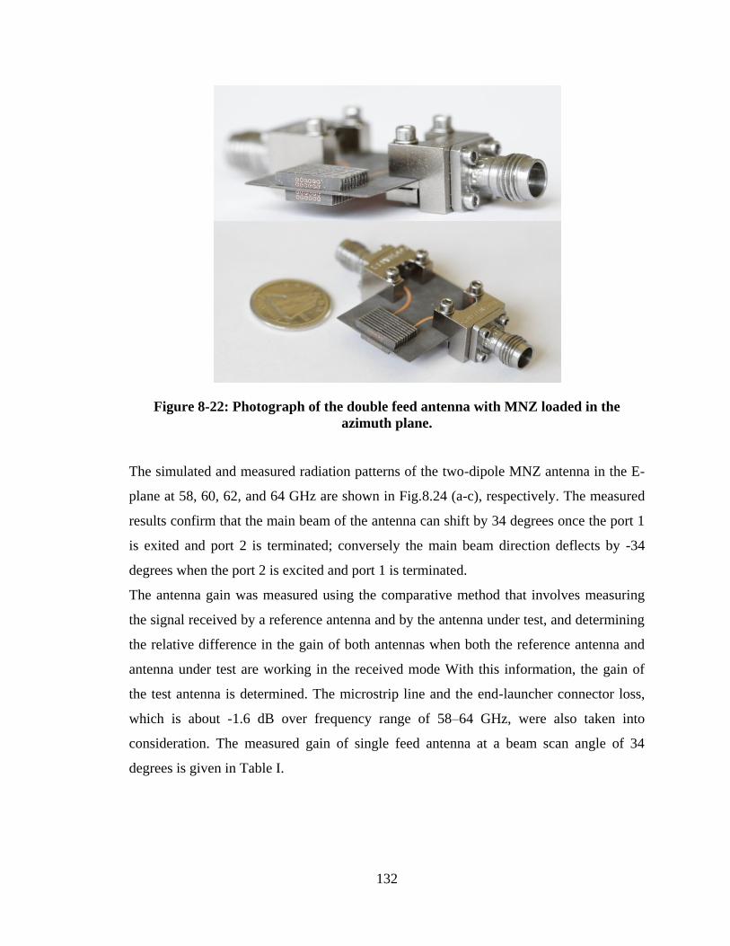
132
Figure 8-22: Photograph of the double feed antenna with MNZ loaded in the
azimuth plane.
The simulated and measured radiation patterns of the two-dipole MNZ antenna in the E-
plane at 58, 60, 62, and 64 GHz are shown in Fig.8.24 (a-c), respectively. The measured
results confirm that the main beam of the antenna can shift by 34 degrees once the port 1
is exited and port 2 is terminated; conversely the main beam direction deflects by -34
degrees when the port 2 is excited and port 1 is terminated.
The antenna gain was measured using the comparative method that involves measuring
the signal received by a reference antenna and by the antenna under test, and determining
the relative difference in the gain of both antennas when both the reference antenna and
antenna under test are working in the received mode With this information, the gain of
the test antenna is determined. The microstrip line and the end-launcher connector loss,
which is about -1.6 dB over frequency range of 58–64 GHz, were also taken into
consideration. The measured gain of single feed antenna at a beam scan angle of 34
degrees is given in Table I.
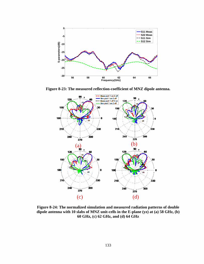
133
Figure 8-23: The measured reflection-coefficient of MNZ dipole antenna.
(a) (b)
(c) (d)
Figure 8-24: The normalized simulation and measured radiation patterns of double
dipole antenna with 10 slabs of MNZ unit-cells in the E-plane (yz) at (a) 58 GHz, (b)
60 GHz, (c) 62 GHz, and (d) 64 GHz
56 58 60 62 64 66-30
-25
-20
-15
-10
-5
0
Frequency(GHz)
S-p
ara
mete
rs(d
B)
S11 Meas
S22 Meas
S11 Sim
S12 Sim
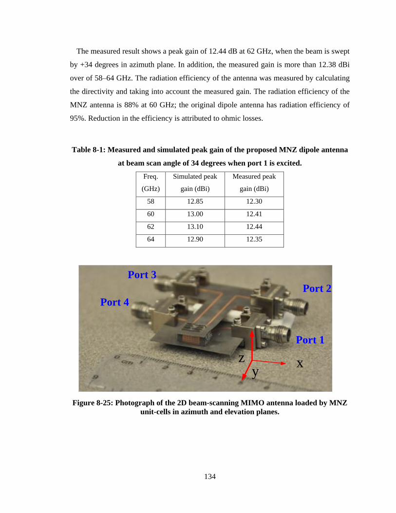
134
The measured result shows a peak gain of 12.44 dB at 62 GHz, when the beam is swept
by +34 degrees in azimuth plane. In addition, the measured gain is more than 12.38 dBi
over of 58–64 GHz. The radiation efficiency of the antenna was measured by calculating
the directivity and taking into account the measured gain. The radiation efficiency of the
MNZ antenna is 88% at 60 GHz; the original dipole antenna has radiation efficiency of
95%. Reduction in the efficiency is attributed to ohmic losses.
Table 8-1: Measured and simulated peak gain of the proposed MNZ dipole antenna
at beam scan angle of 34 degrees when port 1 is excited.
Freq.
(GHz)
Simulated peak
gain (dBi)
Measured peak
gain (dBi)
58 12.85 12.30
60 13.00 12.41
62 13.10 12.44
64 12.90 12.35
xy
z
Port 1
Port 2
Port 3
Port 4
Figure 8-25: Photograph of the 2D beam-scanning MIMO antenna loaded by MNZ
unit-cells in azimuth and elevation planes.
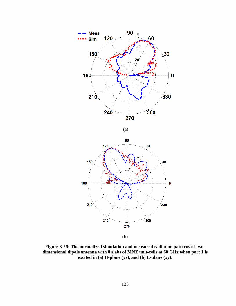
135
(a)
(b)
Figure 8-26: The normalized simulation and measured radiation patterns of two-
dimensional dipole antenna with 8 slabs of MNZ unit-cells at 60 GHz when port 1 is
excited in (a) H-plane (yz), and (b) E-plane (xy).
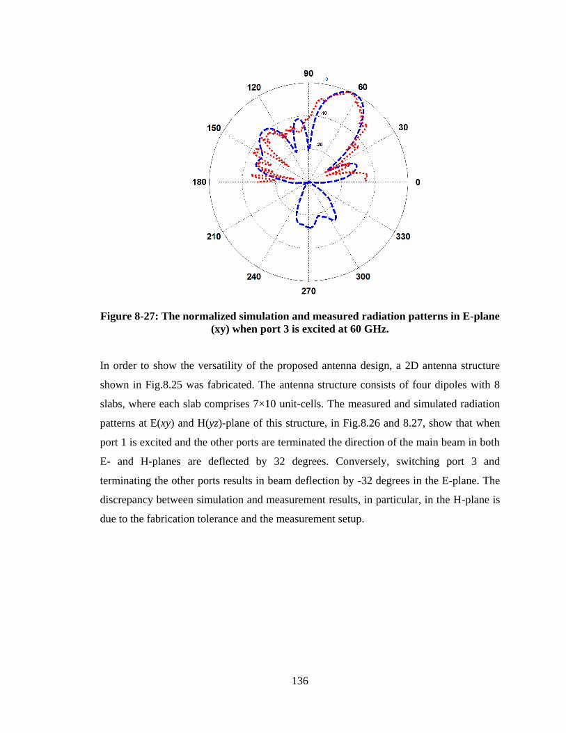
136
Figure 8-27: The normalized simulation and measured radiation patterns in E-plane
(xy) when port 3 is excited at 60 GHz.
In order to show the versatility of the proposed antenna design, a 2D antenna structure
shown in Fig.8.25 was fabricated. The antenna structure consists of four dipoles with 8
slabs, where each slab comprises 7×10 unit-cells. The measured and simulated radiation
patterns at E(xy) and H(yz)-plane of this structure, in Fig.8.26 and 8.27, show that when
port 1 is excited and the other ports are terminated the direction of the main beam in both
E- and H-planes are deflected by 32 degrees. Conversely, switching port 3 and
terminating the other ports results in beam deflection by -32 degrees in the E-plane. The
discrepancy between simulation and measurement results, in particular, in the H-plane is
due to the fabrication tolerance and the measurement setup.
137
8.8 Conclusion
Beamforming antenna has been performed by applying an array of MNZ metamaterial
lens in the azimuth plane of the dipole antenna. The configuration of the MNZ unit-cell is
essentially a split-ring structure with enhanced coupling. Ten slabs were embedded on the
antenna substrate in front of the dipole, where eight slabs were loaded with 4×10 array of
MNZ unit-cells and the two slabs were loaded with 4×6 unit-cells. The simulated and
measured results confirm that the direction of the main beam can be refracted from -34
degrees to 34 degrees in the E-plane (azimuth plane). The peak gain of the antenna is
12.44 dBi at 62 GHz when the beam is tilted by 34 degrees. To realize 2D beamforming
at the same time scanning in the H-plane is necessary. This was achieved by applying
MNZ metamaterial inclusions along the z-direction of the elevation plane (yz). In this
case eight slabs were mounted vertically in front of double dipole antenna where each
slab was loaded with 7×10 unit-cells. The measured results shown confirm that 2D
beamforming is possible. The main beam was swept by 34 degrees in both E- and H-
plane simultaneously. The proposed structure can be scaled to the other frequency bands,
e.g. 28 or 38 GHz for application in 5G MIMO systems.
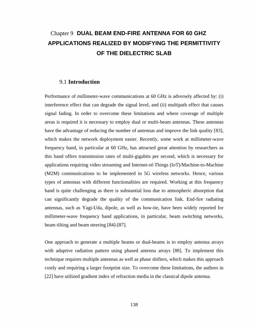
138
Chapter 9 DUAL BEAM END-FIRE ANTENNA FOR 60 GHZ
APPLICATIONS REALIZED BY MODIFYING THE PERMITTIVITY
OF THE DIELECTRIC SLAB
9.1 Introduction
Performance of millimeter-wave communications at 60 GHz is adversely affected by: (i)
interference effect that can degrade the signal level, and (ii) multipath effect that causes
signal fading. In order to overcome these limitations and where coverage of multiple
areas is required it is necessary to employ dual or multi-beam antennas. These antennas
have the advantage of reducing the number of antennas and improve the link quality [83],
which makes the network deployment easier. Recently, some work at millimeter-wave
frequency band, in particular at 60 GHz, has attracted great attention by researchers as
this band offers transmission rates of multi-gigabits per second, which is necessary for
applications requiring video streaming and Internet-of-Things (IoT)/Machine-to-Machine
(M2M) communications to be implemented in 5G wireless networks. Hence, various
types of antennas with different functionalities are required. Working at this frequency
band is quite challenging as there is substantial loss due to atmospheric absorption that
can significantly degrade the quality of the communication link. End-fire radiating
antennas, such as Yagi-Uda, dipole, as well as bow-tie, have been widely reported for
millimeter-wave frequency band applications, in particular, beam switching networks,
beam tilting and beam steering [84]-[87].
One approach to generate a multiple beams or dual-beams is to employ antenna arrays
with adaptive radiation pattern using phased antenna arrays [88]. To implement this
technique requires multiple antennas as well as phase shifters, which makes this approach
costly and requiring a larger footprint size. To overcome these limitations, the authors in
[22] have utilized gradient index of refraction media in the classical dipole antenna.
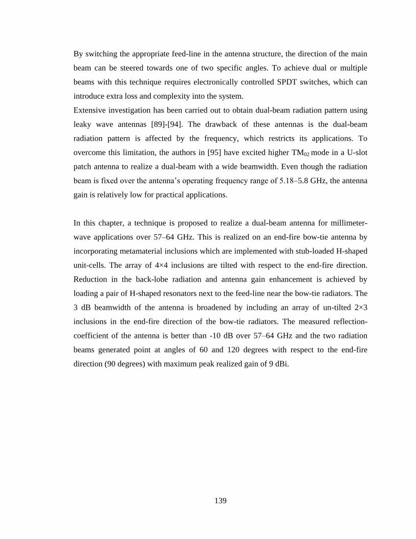
139
By switching the appropriate feed-line in the antenna structure, the direction of the main
beam can be steered towards one of two specific angles. To achieve dual or multiple
beams with this technique requires electronically controlled SPDT switches, which can
introduce extra loss and complexity into the system.
Extensive investigation has been carried out to obtain dual-beam radiation pattern using
leaky wave antennas [89]-[94]. The drawback of these antennas is the dual-beam
radiation pattern is affected by the frequency, which restricts its applications. To
overcome this limitation, the authors in [95] have excited higher TM02 mode in a U-slot
patch antenna to realize a dual-beam with a wide beamwidth. Even though the radiation
beam is fixed over the antenna‟s operating frequency range of 5.18–5.8 GHz, the antenna
gain is relatively low for practical applications.
In this chapter, a technique is proposed to realize a dual-beam antenna for millimeter-
wave applications over 57–64 GHz. This is realized on an end-fire bow-tie antenna by
incorporating metamaterial inclusions which are implemented with stub-loaded H-shaped
unit-cells. The array of 4×4 inclusions are tilted with respect to the end-fire direction.
Reduction in the back-lobe radiation and antenna gain enhancement is achieved by
loading a pair of H-shaped resonators next to the feed-line near the bow-tie radiators. The
3 dB beamwidth of the antenna is broadened by including an array of un-tilted 2×3
inclusions in the end-fire direction of the bow-tie radiators. The measured reflection-
coefficient of the antenna is better than -10 dB over 57–64 GHz and the two radiation
beams generated point at angles of 60 and 120 degrees with respect to the end-fire
direction (90 degrees) with maximum peak realized gain of 9 dBi.
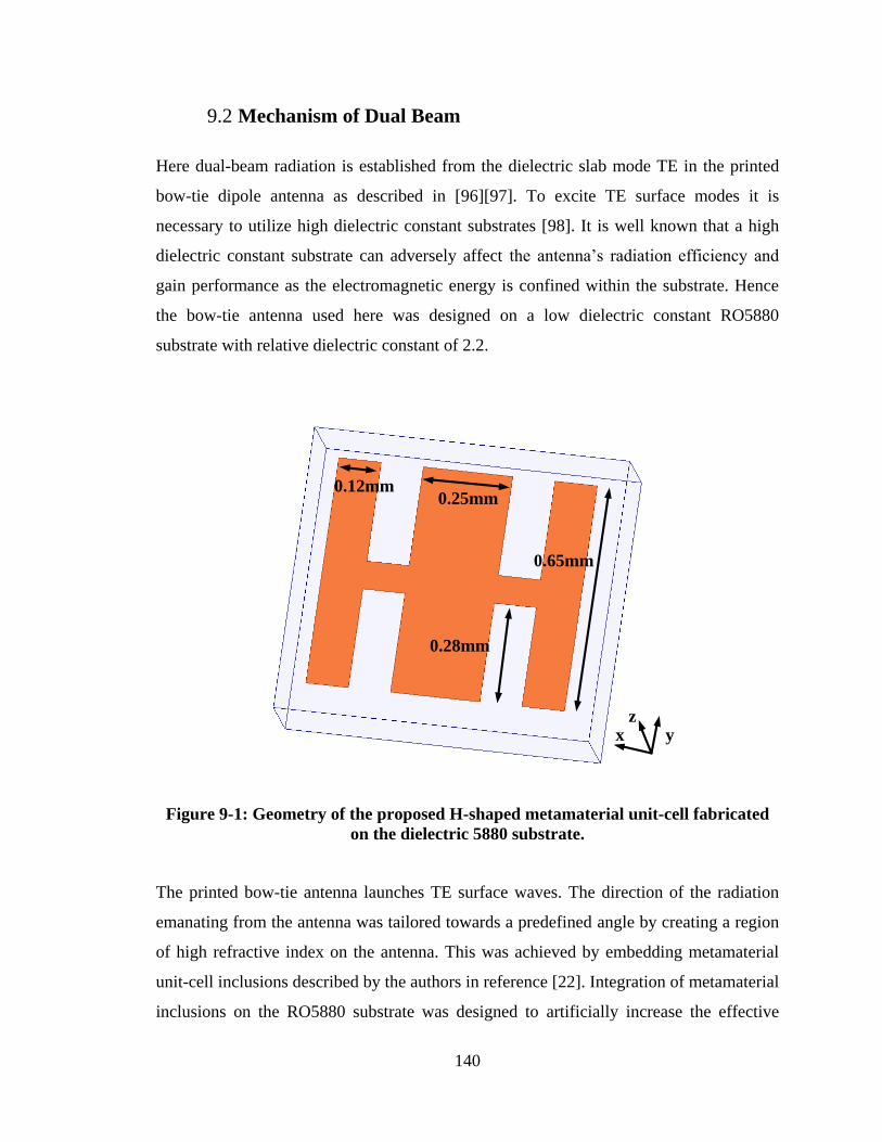
140
9.2 Mechanism of Dual Beam
Here dual-beam radiation is established from the dielectric slab mode TE in the printed
bow-tie dipole antenna as described in [96][97]. To excite TE surface modes it is
necessary to utilize high dielectric constant substrates [98]. It is well known that a high
dielectric constant substrate can adversely affect the antenna‟s radiation efficiency and
gain performance as the electromagnetic energy is confined within the substrate. Hence
the bow-tie antenna used here was designed on a low dielectric constant RO5880
substrate with relative dielectric constant of 2.2.
0.25mm
0.28mm
0.12mm
0.65mm
yz
x
Figure 9-1: Geometry of the proposed H-shaped metamaterial unit-cell fabricated
on the dielectric 5880 substrate.
The printed bow-tie antenna launches TE surface waves. The direction of the radiation
emanating from the antenna was tailored towards a predefined angle by creating a region
of high refractive index on the antenna. This was achieved by embedding metamaterial
unit-cell inclusions described by the authors in reference [22]. Integration of metamaterial
inclusions on the RO5880 substrate was designed to artificially increase the effective
141
dielectric constant of the substrate in order to refract the electromagnetic radiation from
the bow-tie antenna. This technique was implemented here by using an array of stub-
loaded H-shaped electric resonators or unit-cells depicted in Fig. 9.1.
The unit-cell‟s intrinsic parameters were extracted by locating the PEC and PMC
boundary conditions in the yz- and xy-planes with the two wave ports in the y-direction
[21]. Fig.9. 2 shows the real part of permittivity varies from 3.2–7.3 over the frequency
range 57–64 GHz. The corresponding refractive-index varies from 1.81–2.22, which is
larger than antenna substrate with effective refractive-index value of 1.28. By embedding
the proposed unit-cells in front of end-fire radiation causes the antenna to excite surface
waves whose phase velocity is less than the phase velocity of antenna substrate in order
to alter the direction of the radiation.
Figure 9-2: The extracted characterizing parameters of proposed unit-cell including
permittivity, permeability and refractive index.
50 55 60 65 70 75 80-1
0
1
2
3
4
5
6
7
8
9
10
Frequency(GHz)
extr
acte
d
para
mete
rs
Refractive index
Permittivity
Permeability
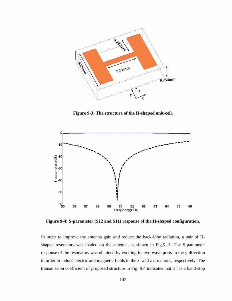
142
xy
z
0.68mm 0.51mm
0.297mm
0.254mm
Figure 9-3: The structure of the H-shaped unit-cell.
Figure 9-4: S-parameter (S12 and S11) response of the H-shaped configuration.
In order to improve the antenna gain and reduce the back-lobe radiation, a pair of H-
shaped resonators was loaded on the antenna, as shown in Fig.9. 3. The S-parameter
response of the resonators was obtained by exciting its two wave ports in the y-direction
in order to induce electric and magnetic fields in the x- and z-directions, respectively. The
transmission coefficient of proposed structure in Fig. 9.4 indicates that it has a band-stop
55 56 57 58 59 60 61 62 63 64 65 66-60
-50
-40
-30
-20
-10
0
Frequency(GHz)
S-p
ara
mete
rs(d
B)
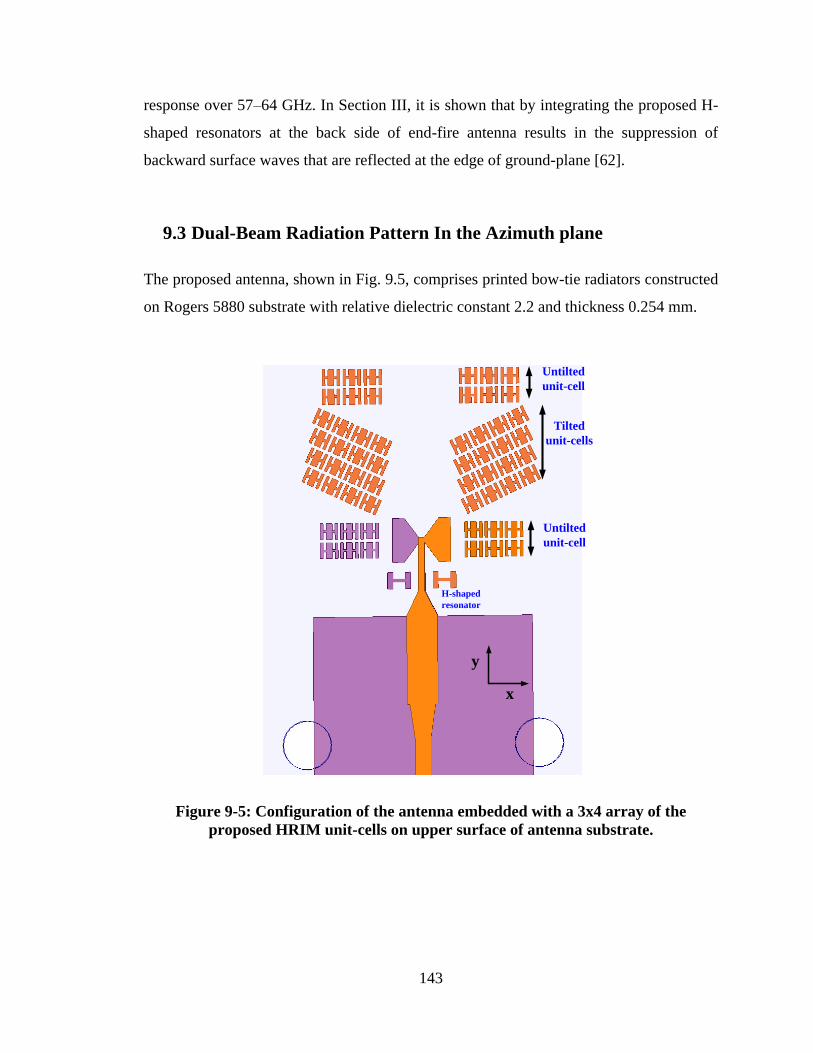
143
response over 57–64 GHz. In Section III, it is shown that by integrating the proposed H-
shaped resonators at the back side of end-fire antenna results in the suppression of
backward surface waves that are reflected at the edge of ground-plane [62].
9.3 Dual-Beam Radiation Pattern In the Azimuth plane
The proposed antenna, shown in Fig. 9.5, comprises printed bow-tie radiators constructed
on Rogers 5880 substrate with relative dielectric constant 2.2 and thickness 0.254 mm.
Tilted
unit-cells
Untilted
unit-cell
Untilted
unit-cell
H-shaped
resonator
x
y
Figure 9-5: Configuration of the antenna embedded with a 3x4 array of the
proposed HRIM unit-cells on upper surface of antenna substrate.
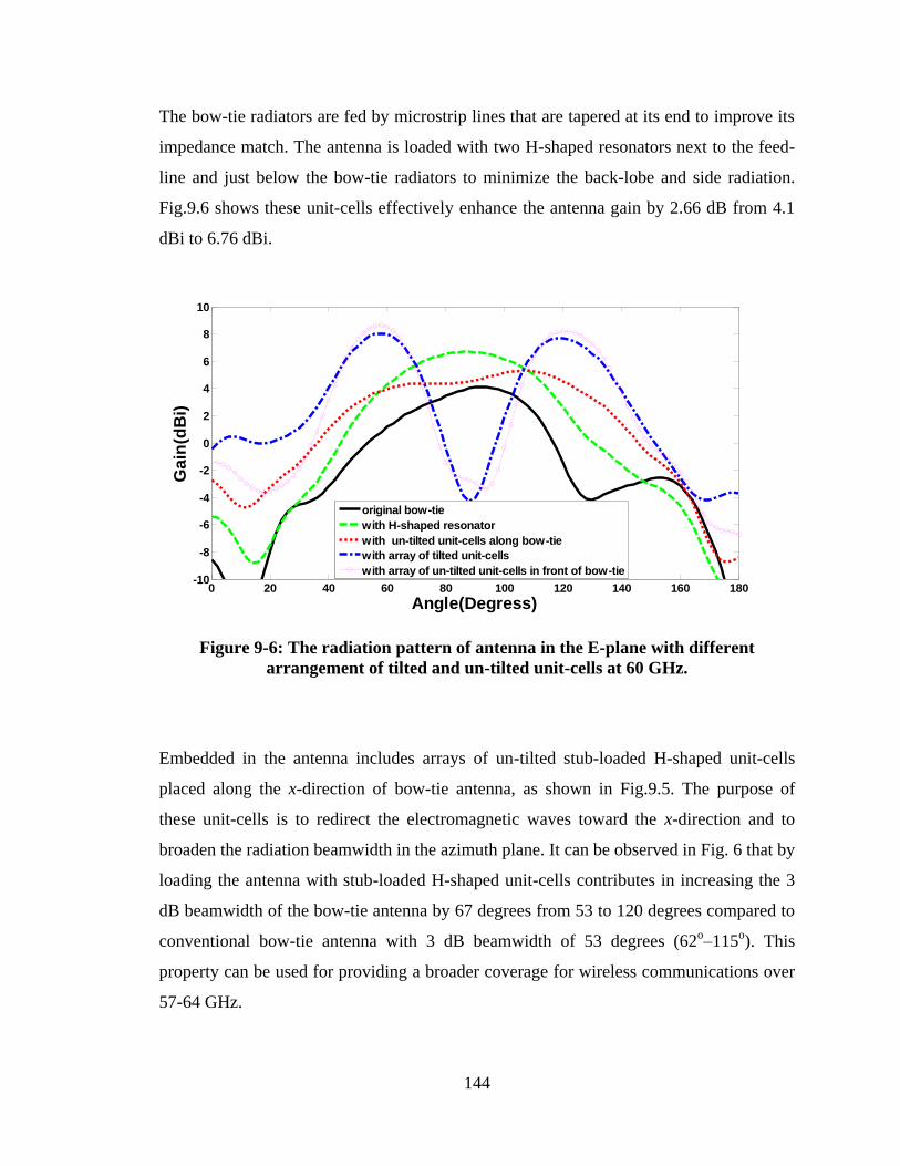
144
The bow-tie radiators are fed by microstrip lines that are tapered at its end to improve its
impedance match. The antenna is loaded with two H-shaped resonators next to the feed-
line and just below the bow-tie radiators to minimize the back-lobe and side radiation.
Fig.9.6 shows these unit-cells effectively enhance the antenna gain by 2.66 dB from 4.1
dBi to 6.76 dBi.
0 20 40 60 80 100 120 140 160 180-10
-8
-6
-4
-2
0
2
4
6
8
10
Angle(Degress)
Ga
in(d
Bi)
original bow-tie
with H-shaped resonator
with un-tilted unit-cells along bow-tie
with array of tilted unit-cells
with array of un-tilted unit-cells in front of bow-tie
Figure 9-6: The radiation pattern of antenna in the E-plane with different
arrangement of tilted and un-tilted unit-cells at 60 GHz.
Embedded in the antenna includes arrays of un-tilted stub-loaded H-shaped unit-cells
placed along the x-direction of bow-tie antenna, as shown in Fig.9.5. The purpose of
these unit-cells is to redirect the electromagnetic waves toward the x-direction and to
broaden the radiation beamwidth in the azimuth plane. It can be observed in Fig. 6 that by
loading the antenna with stub-loaded H-shaped unit-cells contributes in increasing the 3
dB beamwidth of the bow-tie antenna by 67 degrees from 53 to 120 degrees compared to
conventional bow-tie antenna with 3 dB beamwidth of 53 degrees (62o–115
o). This
property can be used for providing a broader coverage for wireless communications over
57-64 GHz.
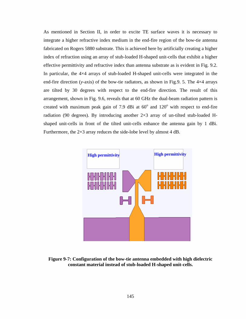
145
As mentioned in Section II, in order to excite TE surface waves it is necessary to
integrate a higher refractive index medium in the end-fire region of the bow-tie antenna
fabricated on Rogers 5880 substrate. This is achieved here by artificially creating a higher
index of refraction using an array of stub-loaded H-shaped unit-cells that exhibit a higher
effective permittivity and refractive index than antenna substrate as is evident in Fig. 9.2.
In particular, the 4×4 arrays of stub-loaded H-shaped unit-cells were integrated in the
end-fire direction (y-axis) of the bow-tie radiators, as shown in Fig.9. 5. The 4×4 arrays
are tilted by 30 degrees with respect to the end-fire direction. The result of this
arrangement, shown in Fig. 9.6, reveals that at 60 GHz the dual-beam radiation pattern is
created with maximum peak gain of 7.9 dBi at 60o and 120
o with respect to end-fire
radiation (90 degrees). By introducing another 2×3 array of un-tilted stub-loaded H-
shaped unit-cells in front of the tilted unit-cells enhance the antenna gain by 1 dBi.
Furthermore, the 2×3 array reduces the side-lobe level by almost 4 dB.
High permittivityHigh permittivity
Figure 9-7: Configuration of the bow-tie antenna embedded with high dielectric
constant material instead of stub-loaded H-shaped unit-cells.
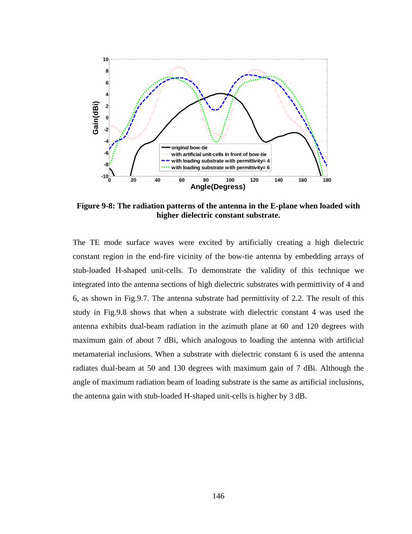
146
Figure 9-8: The radiation patterns of the antenna in the E-plane when loaded with
higher dielectric constant substrate.
The TE mode surface waves were excited by artificially creating a high dielectric
constant region in the end-fire vicinity of the bow-tie antenna by embedding arrays of
stub-loaded H-shaped unit-cells. To demonstrate the validity of this technique we
integrated into the antenna sections of high dielectric substrates with permittivity of 4 and
6, as shown in Fig.9.7. The antenna substrate had permittivity of 2.2. The result of this
study in Fig.9.8 shows that when a substrate with dielectric constant 4 was used the
antenna exhibits dual-beam radiation in the azimuth plane at 60 and 120 degrees with
maximum gain of about 7 dBi, which analogous to loading the antenna with artificial
metamaterial inclusions. When a substrate with dielectric constant 6 is used the antenna
radiates dual-beam at 50 and 130 degrees with maximum gain of 7 dBi. Although the
angle of maximum radiation beam of loading substrate is the same as artificial inclusions,
the antenna gain with stub-loaded H-shaped unit-cells is higher by 3 dB.
0 20 40 60 80 100 120 140 160 180-10
-8
-6
-4
-2
0
2
4
6
8
10
Angle(Degress)
Ga
in(d
Bi)
original bow-tie
with artificial unit-cells in front of bow-tie
with loading substrate with permittivity= 4
with loading substrate with permittivity= 6
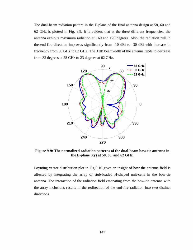
147
The dual-beam radiation pattern in the E-plane of the final antenna design at 58, 60 and
62 GHz is plotted in Fig. 9.9. It is evident that at the three different frequencies, the
antenna exhibits maximum radiation at +60 and 120 degrees. Also, the radiation null in
the end-fire direction improves significantly from -10 dBi to -30 dBi with increase in
frequency from 58 GHz to 62 GHz. The 3 dB beamwidth of the antenna tends to decrease
from 32 degrees at 58 GHz to 23 degrees at 62 GHz.
-20
-10
0
30
210
60
240
90
270
120
300
150
330
180 0
58 GHz
60 GHz
62 GHz
Figure 9-9: The normalized radiation patterns of the dual-beam bow-tie antenna in
the E-plane (xy) at 58, 60, and 62 GHz.
Poynting vector distribution plot in Fig.9.10 gives an insight of how the antenna field is
affected by integrating the array of stub-loaded H-shaped unit-cells in the bow-tie
antenna. The interaction of the radiation field emanating from the bow-tie antenna with
the array inclusions results in the redirection of the end-fire radiation into two distinct
directions.
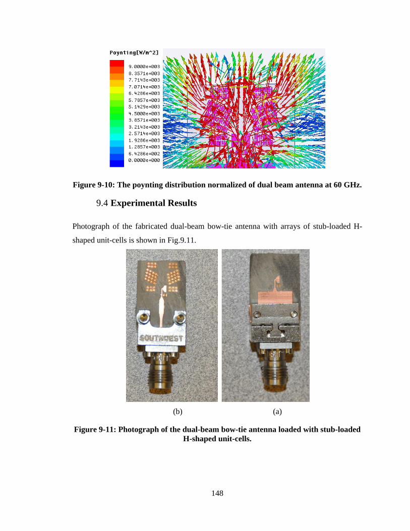
148
Figure 9-10: The poynting distribution normalized of dual beam antenna at 60 GHz.
9.4 Experimental Results
Photograph of the fabricated dual-beam bow-tie antenna with arrays of stub-loaded H-
shaped unit-cells is shown in Fig.9.11.
(b) (a)
Figure 9-11: Photograph of the dual-beam bow-tie antenna loaded with stub-loaded
H-shaped unit-cells.
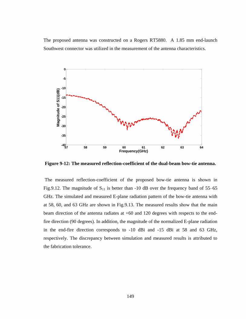
149
The proposed antenna was constructed on a Rogers RT5880. A 1.85 mm end-launch
Southwest connector was utilized in the measurement of the antenna characteristics.
Figure 9-12: The measured reflection-coefficient of the dual-beam bow-tie antenna.
The measured reflection-coefficient of the proposed bow-tie antenna is shown in
Fig.9.12. The magnitude of S11 is better than -10 dB over the frequency band of 55–65
GHz. The simulated and measured E-plane radiation pattern of the bow-tie antenna with
at 58, 60, and 63 GHz are shown in Fig.9.13. The measured results show that the main
beam direction of the antenna radiates at +60 and 120 degrees with respects to the end-
fire direction (90 degrees). In addition, the magnitude of the normalized E-plane radiation
in the end-fire direction corresponds to -10 dBi and -15 dBi at 58 and 63 GHz,
respectively. The discrepancy between simulation and measured results is attributed to
the fabrication tolerance.
57 58 59 60 61 62 63 64-40
-35
-30
-25
-20
-15
-10
-5
0
Frequency(GHz)
Mag
nit
ud
e o
f S
11(d
B)
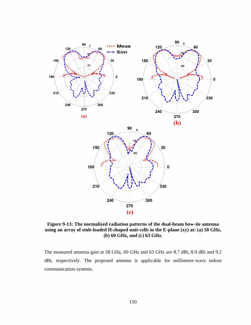
150
Figure 9-13: The normalized radiation patterns of the dual-beam bow-tie antenna
using an array of stub-loaded H-shaped unit-cells in the E-plane (xy) at: (a) 58 GHz,
(b) 60 GHz, and (c) 63 GHz.
The measured antenna gain at 58 GHz, 60 GHz and 63 GHz are 8.7 dBi, 8.9 dBi and 9.2
dBi, respectively. The proposed antenna is applicable for millimeter-wave indoor
communication systems.
151
9.5 Conclusion
It has been demonstrated that by artificially manipulating the dielectric constant of the
substrate in the end-fire direction of a bow-tie antenna a dual-beam radiation pattern can
be realized in the E-plane at 60 GHz. This is achieved using 4×4 arrays of metamaterial
inclusions implemented using stub-loaded H-shaped unit-cells. By appropriately tilting
the inclusions with respect to the bow-tie axis a dual-beam was created at +60 and 120
degrees. In addition, it was shown that by including a pair of H-shape resonators in the
vicinity of the feed-line and the radiators the back-lobe radiation is reduced and the
antenna gain enhanced by 2.66 dB. Inclusion of a further 2×3 array of metamaterial
inclusions was used to broaden the 3 dB beamwidth of the antenna and enhances its gain
by 1 dB. The measured results of the prototype antenna agree well with the simulation
results. This antenna exhibits desirable characteristics for indoor communications at 60
GHz.
152
Chapter 10 CONCLUSION AND FEAUTURE WORK
10.1 Conclusion
This dissertation presented an innovative approach for tilting the direction of the main
beam from an end-fire antenna in both azimuth and elevation planes utilizing matasurface
and metamaterial unit-cells. Tilting the antenna‟s main beam finds application in mobile
base-stations to create smaller cells and increase system capacity. The metamaterial unit-
cell was implemented using a novel electric resonator with meander-line H-shape
geometry. Array of metamaterial unit-cells were integrated with the bow-tie antenna
designed to operate between 7-8 GHz. In order to realize a larger tilt angle and high
realized gain it was necessary to integrate into the bow-tie antenna an array of 5x4 unit-
cells in the azimuth plane. The measured tilt angles was 17 degrees in the E-plane at 7.5
GHz with maximum peak realized gain of 9.3 dBi. Split-ring resonators (SRR) were used
to enhance the tilt angle in the elevation plane of the bow-tie antenna. Integrating an array
of inhomogenous SRRs in the elevation plane (H-plane) expended solely in the y- and z-
directions provided a tilt angle of 30 degrees with gain enhancement of 5 dBi at 3.5 GHz.
These results show the proposed approach is suitable for next generation of base-station
antenna operating at the WiMAX frequency band. The side-lobe level (SLL) of radiation
patterns in the H-plane is about -8 dB. To enhance the SLL it was necessary to increase
the number of unit-cells in the end-fire direction, which however increases the protrusion
dimension of antenna.
Millimeter-frequency band at 60 GHz is necessary to increase the transmission
data rate more than 1.5 Gb/s because of its large bandwidth extending from 57-64 GHz.
Operating at this frequency band incurs greater attenuation loss (10–16 dB/km) due to
atmospheric absorption, which can be compensated by using high-gain antenna arrays.
To avoid antenna arrays, the work in this thesis proposes using a bow-tie antenna fed by
substrate integrated waveguide (SIW), which acts as a wideband balun over 57-64 GHz.
153
To increase the antenna gain entails (i) tilting the bow-tie radiators with respect to the
end-fire direction, which increases the aperture size of the antenna and hence its gain, (ii)
loading split-ring resonators at the back side of the bow-tie antenna to direct the energy
toward the end-fire direction and improve its back-lobe level in the H-plane, and (iii)
integrate in front of the bow-tie antenna an array of zero index metamaterial unit-cells to
convert the spherical waves from the antenna into the planar waves. The measured
antenna gain was 12.3 dBi over 57-64 GHz.
A high gain antenna makes the beamwidth narrower that makes signal alignment
challenging between the transmitter and receiver. To deal with this issue a beamforming
approach using phased antenna arrays was proposed. This involved using stub-loaded H-
shape resonators, where the length and width of the stub is changed to alter its phase
response over 57-64 GHz. By integrating an array of stub-loaded H-shape resonators in
the off-axis of a classical dipole antenna is shown to deflect its peak radiation beam in the
E-plane by 26 degrees. To implement a beam switching, another dipole antenna was
embedded on the other side of GRIM unit-cells. By exciting the appropriate feed-line to
the antenna its radiation beam can be switched from -26 to 26 degrees. The measurement
results reveal that with this technique the radiation beam can be scanned from -58 to +58
degrees over 57-64 GHz. The gain of antenna when the beam is scanned was 10 dBi at 63
GHz.
To obtain a greater tilt angle and higher gain, an array of mu-near zero (MNZ)
unit-cells created with split-ring resonator was proposed. Integrating an array of MNZ
inclusions in the off-axis of the dipole antenna in both azimuth and elevation planes
resulted in tilt angle of 35 degrees with gain enhancement of 8 dBi. In fact with this
technique it was shown 2-dimensional beam scanning can be achieved with maximum
peak gain of 14.3 dBi at 60 GHz.
Leaky wave antenna is another promising technique for creating dual beam
radiation. In fact, dual beam radiation can be employed in WLAN and at millimeter-wave
bands to improve the link quality. However, the radiation of leaky wave antenna changes
with the frequency which restricts its application. Hence, in the thesis a novel technique
is proposed to achieve a dual beam radiation with a fixed beam antenna for operation
over 57-64 GHz. This was realized by integrating an array of stub-loaded H-shaped unit-
154
cells in front of bow-tie antenna. The measured result show that the peak radiation in the
E-plane is directed at +30 and -30 degrees with respect to end-fire radiation over 57-64
GHz.
10.2 Future work
As shown above the beam tilting in both azimuth and elevation plane can be realized
using array of metasurface and metamaterial unit-cells. To switch the radiation beam it is
necessary to embed SP4T switch into the feed-line. In the above research work SP4T
switch was not used due to time constraint however it has been shown this functionality
can be included. Hence, electronic switching needs to be investigated to determine how
the switch would affect the tilt angle and the overall antenna performance. Furthermore,
the parametric study undertaken shows that by increasing the number of unit-cells in a
desired direction leads to in the increase of the tilt angle. It would be interesting to
integrate into the unit-cells PIN or varactor diodes to control the direction of the tilt angle
and its beamwidth. This would enable the development of an antenna whose radiation
pattern can be electronically reconfigured in both planes. In Chapter 5, a high gain bow-
tie antenna was implemented using a single antenna with maximum peak gain of 12.3 dBi
over 57-64 GHz. To obtain higher gain up to 18 dBi, it would be interesting to see how
this can be achieved by deploying a larger number of arrays.
155
Chapter 11 RESUME
11.1 Introduction
La bande ISM 60 GHz (57-64 GHz) a suscité un grand intérêt chez plusieurs chercheurs
et industriels pour sa large bande passante. Cette bande permet la transmission de
données à un débit de plusieurs Gb/sde sortes à couvrir plusieurs applications dans le
domaine des communications sans fil. Toutefois, en raison de la forte affaiblissement
causé par le phénomène d‟absorption atmosphérique dans cette bande, le signal propagé
est considérablement réduit. Ce problème peut être résolu par l‟utilisation des antennes à
gain élevé. Cependant, l‟alignement du faisceau rayonnant principal est un autre défi pour
les antennes à gain élevé, où l‟emplacement de l‟émetteur ou le récepteur n‟est toujours
pas fixe. La solution pour régler ce problème est d‟utiliser les réseaux à commutation ou
à balayage de faisceaux comme dans les réseaux d‟antennes à déphasage. Cependant, ces
réseaux d‟antennes à phasage souffrent énormément des pertes d‟insertion causées par
leur circuit d‟alimentation, et ils sont aussi complexes à concevoir, ce qui les rend une
solution moins attractive pour les systèmes de communication sans fil. Pour surmonter
ces difficultés, on propose dans le cadre de cette thèse de nouvelles solutions pour
contrôler électroniquement l‟inclinaison de faisceau rayonnant en utilisant des structures
en métamatériaux pour des applications en micro-ondes et en ondes millimétriques.
En premier lieu, nous avons conçu une structure en métamatériaux sous forme d‟un
réseau de résonateurs à ligne de méandre en forme de H, qui fonctionne comme une
métasurface anisotrope dans bande C. Cette structure a été installée devant une antenne
standard de type nœud papillon pour incliner la direction de faisceau principal dans le
plan azimutal. De plus, pour incliner également le faisceau de rayonnement d‟antenne
dans le plan d‟élévation, une seconde structure sous forme d‟un réseau de résonateurs en
anneau non-homogènes a été placée dans le plan du champ magnétique de l‟antenne. Ces
deux structures fournissent une solution viable pour contrôler simultanément
156
l‟inclinaison du faisceau principal dans les deux plans de l‟antenne. Ceci pourrait être une
solution viable pour les antennes de station de base de la prochaine génération qui ont
besoin de contrôler d‟inclinaison de la direction de faisceau principal dans les deux plans
(azimut et élévation). Cela comprend notamment les réseaux sans fil cellulaires 5G pour
lesquels on envisage d‟exploiter les ondes millimétriques. La technique proposée est
également applicable à la bande C (7-8 GHz) et WiMAX bande (3,4-3,6 GHz).
En second lieu, nous avons conçu une antenne à gain élevé opérant dans les ondes
millimétriques (57-64 GHz). Cette antenne utilise une configuration sous forme de nœud
papillon et qui est alimentée par un guide d‟onde intégré au substrat (Surface integrated
waveguide :SIW). La technique qu‟on propose pour accroitre le gain d‟antenne implique
(i) intégrer un résonateur en fente annulaire à l‟arrière d‟antenne en nœud papillon; (ii)
incliner le faisceau de l‟antenne en forme de nœud papillon selon la direction longitudinal
(end-fire) ; (iii) intégrer un réseau de résonateurs repliés en forme de H afin de créer une
région à indice de réfraction faible devant l‟antenne pour convertir les ondes sphériques
en ondes planaires. Les résultats obtenus indiquent que le gain d‟antenne est amélioré
pour atteindre 12 dBi de 57 à 64 GHz.
En troisième lieu, une autre technique a été proposée pour dévier le faisceau principal
d‟une antenne dipôle standard. Cette technique vise à créer un milieu à gradient d‟indice
de réfraction dans le plan azimutal. En utilisant cette approche, on a réussi à effectuer une
commutation de faisceau de -58 à +58 degrés dans la bande entre 57 et 64 GHz et
produire un gain maximal de 9.5 dBi à 60 GHz. De plus, afin de diriger le faisceau dans
le plan d‟élévation, on a utilisé des résonateurs repliés en forme de H chargés dans les
plans magnétique et électrique. Cette configuration a permis d‟obtenir une inclinaison ou
une commutation de faisceau bidimensionnelle à 60 GHz. Toutefois, dans cette
configuration le gain d‟antenne se limite à 10 dBi et la déviation de faisceau se limite a
17 dégrées dans les deux plans.
En quatrième lieu, pour produire à un gain et un angle d‟inclinaison plus élevés, un
réseau de résonateurs enfentes annulaires a été placé devant une source quasi-TE générée
par une antenne dipôle à 60 GHz. La résonance magnétique du réseau a produit un angle
d‟inclinaison de 34 degrés dans les plans d‟azimutal et d‟élévation et un gain maximal de
14 dBi dans la bande de 57 à 64 GHz.
157
Enfin, une dernière technique a été proposée qui utilise un réseau de résonateurs en forme
de H et qui est placé devant une antenne en forme de nœud papillon pour obtenir un
double faisceau et un rayonnement à large bande dans le plan azimutal de l‟antenne. Les
résultats obtenus indiquent que une l‟inclinaison de faisceau est de +30 à -30 degrés dans
le plan longitudinal de l‟antenne et un gain maximal de 9 dBi à 60 GHz.
11.2 Antenne à inclinaison de faisceau en utilisant des
métamatériaux
Cette section présente une technique pour réorienter le faisceau de rayonnement d‟une
antenne planaire dans une direction déterminée en utilisant une structure en
métamatériau. Dans cette approche, on a exploité l‟effet du changement de phase
résultant de la propagation d‟une onde électromagnétique en traversant d‟un milieu à un
autre ayant un indice de réfraction différant. Pour cela, une structure de cellule unitaire en
métamatériau en forme de H a été conçue pour donner un indice de réfraction élevé qui a
servi à mettre en œuvre l‟inclinaison du faisceau d‟une antenne en forme de nœud
papillon. La cellule unitaire a été fabriquée et caractérisée en mesurant de ses paramètres
S. Utilisant cette cellule unitaire, on a également construit un réseau bidimensionnel pour
créer une région d‟indice de réfraction élevé laquelle on a appliquée à proximité d‟une
antenne en forme de nœud papillon pour incliner le faisceau principal de l‟antenne. Les
résultats expérimentaux et les résultats simulés indiquent que le faisceau principal
d‟antenne dans le plan électrique est incliné de 17 degrés par rapport à la direction à
rayonnement longitudinal aux fréquences : 7,3, 7,5 et 7,7 GHz. Les résultats montrent
aussi que contrairement aux antennes classiques à inclinaison de faisceau, une chute du
gain n‟est pas remarquée quand le faisceau est incliné ; en fait, il résulte une amélioration
du gain à 2,73 dB, comparativement à l‟antenne originelle en forme de nœud papillon à
7,5 GHz. Le coefficient de réflexion d‟antenne reste <-10 dB dans la gamme de
fréquence d‟opération.
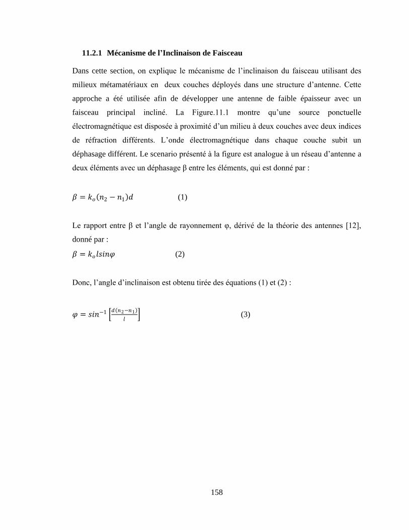
158
11.2.1 Mécanisme de l’Inclinaison de Faisceau
Dans cette section, on explique le mécanisme de l‟inclinaison du faisceau utilisant des
milieux métamatériaux en deux couches déployés dans une structure d‟antenne. Cette
approche a été utilisée afin de développer une antenne de faible épaisseur avec un
faisceau principal incliné. La Figure.11.1 montre qu‟une source ponctuelle
électromagnétique est disposée à proximité d‟un milieu à deux couches avec deux indices
de réfraction différents. L‟onde électromagnétique dans chaque couche subit un
déphasage différent. Le scenario présenté à la figure est analogue à un réseau d‟antenne a
deux éléments avec un déphasage β entre les éléments, qui est donné par :
𝛽 = 𝑘𝑜 𝑛2 − 𝑛1 𝑑 (1)
Le rapport entre β et l‟angle de rayonnement φ, dérivé de la théorie des antennes [12],
donné par :
𝛽 = 𝑘𝑜 𝑙𝑠𝑖𝑛𝜑 (2)
Donc, l‟angle d‟inclinaison est obtenu tirée des équations (1) et (2) :
𝜑 = 𝑠𝑖𝑛−1 𝑑 𝑛2−𝑛1
𝑙 (3)
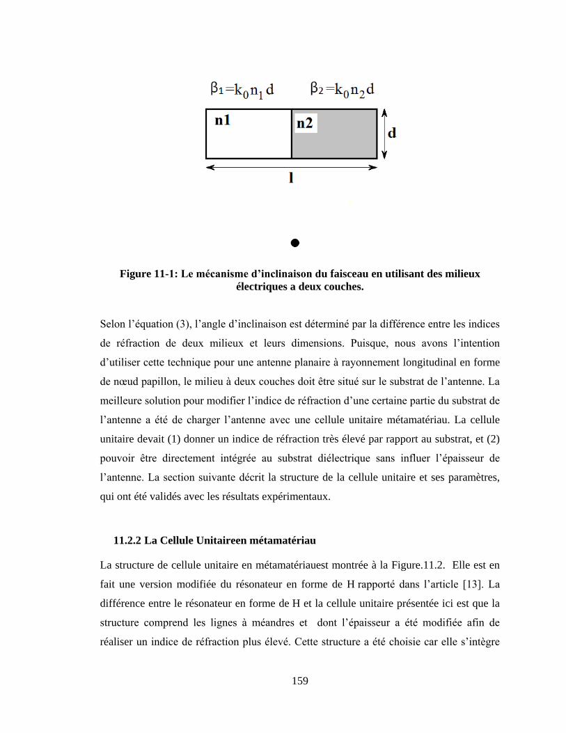
159
Figure 11-1:Lemécanismed’inclinaisondu faisceau en utilisant des milieux
électriques a deux couches.
Selon l‟équation (3), l‟angle d‟inclinaison est déterminé par la différence entre les indices
de réfraction de deux milieux et leurs dimensions. Puisque, nous avons l‟intention
d‟utiliser cette technique pour une antenne planaire à rayonnement longitudinal en forme
de nœud papillon, le milieu à deux couches doit être situé sur le substrat de l‟antenne. La
meilleure solution pour modifier l‟indice de réfraction d‟une certaine partie du substrat de
l‟antenne a été de charger l‟antenne avec une cellule unitaire métamatériau. La cellule
unitaire devait (1) donner un indice de réfraction très élevé par rapport au substrat, et (2)
pouvoir être directement intégrée au substrat diélectrique sans influer l‟épaisseur de
l‟antenne. La section suivante décrit la structure de la cellule unitaire et ses paramètres,
qui ont été validés avec les résultats expérimentaux.
11.2.2 La Cellule Unitaireen métamatériau
La structure de cellule unitaire en métamatériauest montrée à la Figure.11.2. Elle est en
fait une version modifiée du résonateur en forme de H rapporté dans l‟article [13]. La
différence entre le résonateur en forme de H et la cellule unitaire présentée ici est que la
structure comprend les lignes à méandres et dont l‟épaisseur a été modifiée afin de
réaliser un indice de réfraction plus élevé. Cette structure a été choisie car elle s‟intègre
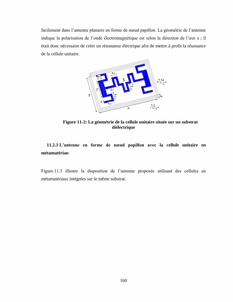
160
facilement dans l‟antenne planaire en forme de nœud papillon. La géométrie de l‟antenne
indique la polarisation de l‟onde électromagnétique est selon la direction de l‟axe x ; il
était donc nécessaire de créer un résonateur électrique afin de mettre à profit la résonance
de la cellule unitaire.
Figure 11-2: La géométrie de la cellule unitaire située sur un substrat
diélectrique
11.2.3 L’antenne en forme de nœud papillon avec la cellule unitaire en
métamatériau
Figure.11.3 illustre la disposition de l‟antenne proposée utilisant des cellules en
métamatériaux intégrées sur le même substrat.
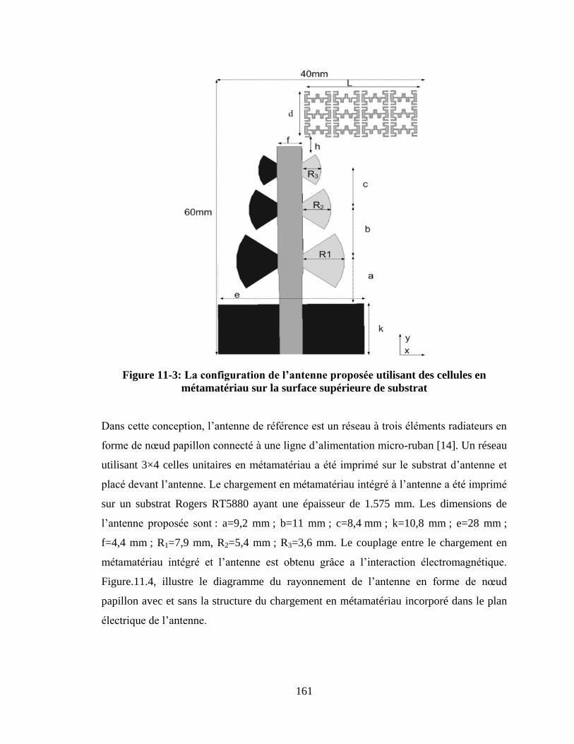
161
Figure 11-3: Laconfigurationdel’antenneproposéeutilisant des cellules en
métamatériau sur la surface supérieure de substrat
Dans cette conception, l‟antenne de référence est un réseau à trois éléments radiateurs en
forme de nœud papillon connecté à une ligne d‟alimentation micro-ruban [14]. Un réseau
utilisant 3×4 celles unitaires en métamatériau a été imprimé sur le substrat d‟antenne et
placé devant l‟antenne. Le chargement en métamatériau intégré à l‟antenne a été imprimé
sur un substrat Rogers RT5880 ayant une épaisseur de 1.575 mm. Les dimensions de
l‟antenne proposée sont : a=9,2 mm ; b=11 mm ; c=8,4 mm ; k=10,8 mm ; e=28 mm ;
f=4,4 mm ; R1=7,9 mm, R2=5,4 mm ; R3=3,6 mm. Le couplage entre le chargement en
métamatériau intégré et l‟antenne est obtenu grâce a l‟interaction électromagnétique.
Figure.11.4, illustre le diagramme du rayonnement de l‟antenne en forme de nœud
papillon avec et sans la structure du chargement en métamatériau incorporé dans le plan
électrique de l‟antenne.
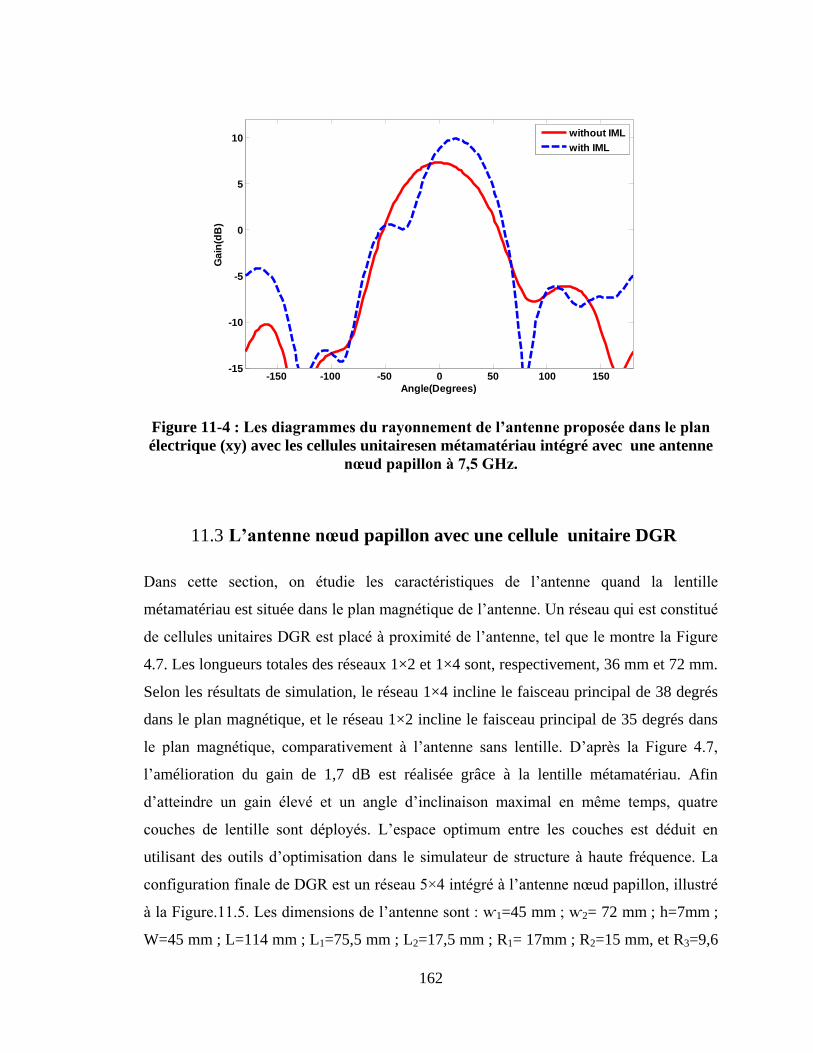
162
Figure 11-4 :Lesdiagrammesdurayonnementdel’antenneproposéedansleplan
électrique (xy) avec les cellules unitairesen métamatériau intégré avec une antenne
nœudpapillonà7,5GHz.
11.3 L’antennenœud papillon avec une cellule unitaire DGR
Dans cette section, on étudie les caractéristiques de l‟antenne quand la lentille
métamatériau est située dans le plan magnétique de l‟antenne. Un réseau qui est constitué
de cellules unitaires DGR est placé à proximité de l‟antenne, tel que le montre la Figure
4.7. Les longueurs totales des réseaux 1×2 et 1×4 sont, respectivement, 36 mm et 72 mm.
Selon les résultats de simulation, le réseau 1×4 incline le faisceau principal de 38 degrés
dans le plan magnétique, et le réseau 1×2 incline le faisceau principal de 35 degrés dans
le plan magnétique, comparativement à l‟antenne sans lentille. D‟après la Figure 4.7,
l‟amélioration du gain de 1,7 dB est réalisée grâce à la lentille métamatériau. Afin
d‟atteindre un gain élevé et un angle d‟inclinaison maximal en même temps, quatre
couches de lentille sont déployés. L‟espace optimum entre les couches est déduit en
utilisant des outils d‟optimisation dans le simulateur de structure à haute fréquence. La
configuration finale de DGR est un réseau 5×4 intégré à l‟antenne nœud papillon, illustré
à la Figure.11.5. Les dimensions de l‟antenne sont : ⱳ1=45 mm ; ⱳ2= 72 mm ; h=7mm ;
W=45 mm ; L=114 mm ; L1=75,5 mm ; L2=17,5 mm ; R1= 17mm ; R2=15 mm, et R3=9,6
-150 -100 -50 0 50 100 150-15
-10
-5
0
5
10
Angle(Degrees)
Ga
in(d
B)
without IML
with IML
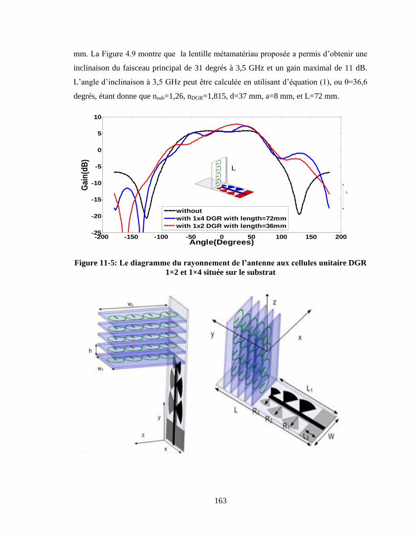
163
mm. La Figure 4.9 montre que la lentille métamatériau proposée a permis d‟obtenir une
inclinaison du faisceau principal de 31 degrés à 3,5 GHz et un gain maximal de 11 dB.
L‟angle d‟inclinaison à 3,5 GHz peut être calculée en utilisant d‟équation (1), ou θ=36,6
degrés, étant donne que nsub=1,26, nDGR=1,815, d=37 mm, a=8 mm, et L=72 mm.
L
L
-200 -150 -100 -50 0 50 100 150 200-25
-20
-15
-10
-5
0
5
10
Angle(Degrees)
Ga
in(d
B)
without
with 1x4 DGR with length=72mm
with 1x2 DGR with length=36mm
L
Figure 11-5: Lediagrammedurayonnementdel’antenneauxcellulesunitaire DGR
1×2 et 1×4 située sur le substrat
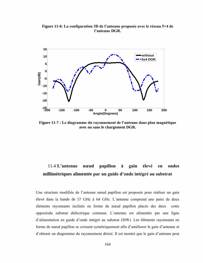
164
Figure 11-6: Laconfiguration3Ddel’antenneproposéeavecleréseau5×4de
l’antenneDGR.
Figure 11-7 :Lediagrammedurayonnementdel’antennedansplanmagnétique
avec ou sans le chargement DGR.
11.4 L’antenne nœud papillon à gain élevé en ondes
millimétriques alimentée parunguided’ondeintégréausubstrat
Une structure modifiée de l‟antenne nœud papillon est proposée pour réaliser un gain
élevé dans la bande de 57 GHz à 64 GHz. L‟antenne comprend une paire de deux
éléments rayonnants inclinés en forme de nœud papillon placés des deux cotés
opposésdu substrat diélectrique commun. L‟antenne est alimentée par une ligne
d‟alimentation en guide d‟onde intégré au substrat (SIW). Les éléments rayonnants en
forme de nœud papillon se croisent symétriquement afin d‟améliorer le gain d‟antenne et
d‟obtenir un diagramme du rayonnement désiré. Il est montré que le gain d‟antenne peut
-200 -150 -100 -50 0 50 100 150 200-25
-20
-15
-10
-5
0
5
10
15
Angle(Degrees)
Gain
(dB
)
without
5x4 DGR
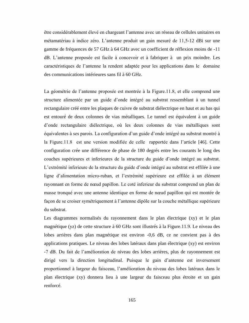
165
être considérablement élevé en chargeant l‟antenne avec un réseau de cellules unitaires en
métamatériau à indice zéro. L‟antenne produit un gain mesuré de 11,5-12 dBi sur une
gamme de fréquences de 57 GHz à 64 GHz avec un coefficient de réflexion moins de -11
dB. L‟antenne proposée est facile à concevoir et à fabriquer à un prix moindre. Les
caractéristiques de l‟antenne la rendent adaptée pour les applications dans le domaine
des communications intérieures sans fil à 60 GHz.
La géométrie de l‟antenne proposée est montrée à la Figure.11.8, et elle comprend une
structure alimentée par un guide d‟onde intégré au substrat ressemblant à un tunnel
rectangulaire créé entre les plaques de cuivre de substrat diélectrique en haut et au bas qui
est entouré de deux colonnes de vias métalliques. Le tunnel est équivalent à un guide
d‟onde rectangulaire diélectrique, où les deux colonnes de vias métalliques sont
équivalentes à ses parois. La configuration d‟un guide d‟onde intégré au substrat montré à
la Figure.11.8 est une version modifiée de celle rapportée dans l‟article [46]. Cette
configuration crée une différence de phase de 180 degrés entre les courants le long des
couches supérieures et inferieures de la structure du guide d‟onde intégré au substrat.
L‟extrémité inferieure de la structure du guide d‟onde intégré au substrat est effilée à une
ligne d‟alimentation micro-ruban, et l‟extrémité supérieure est effilée à un élément
rayonnant en forme de nœud papillon. Le coté inferieur du substrat comprend un plan de
masse tronqué avec une antenne identique en forme de nœud papillon qui est montée de
façon de se croiser symétriquement à l‟antenne dipôle sur la couche métallique supérieure
du substrat.
Les diagrammes normalisés du rayonnement dans le plan électrique (xy) et le plan
magnétique (yz) de cette structure à 60 GHz sont illustrés à la Figure.11.9. Le niveau des
lobes arrières dans plan magnétique est environ -0,6 dB, ce ne convient pas à des
applications pratiques. Le niveau des lobes latéraux dans plan électrique (xy) est environ
-7 dB. Du fait de l‟amélioration de niveau des lobes arrières, plus de rayonnement est
dirigé vers la direction longitudinal. Puisque le gain d‟antenne est inversement
proportionnel à largeur du faisceau, l‟amélioration du niveau des lobes latéraux dans le
plan électrique (xy) donnera lieu à une largeur du faisceau plus étroite et un gain
renforcé.
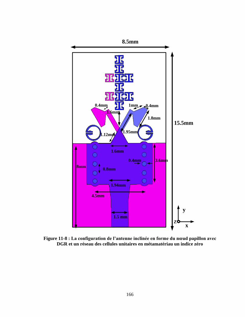
166
Figure 11-8 :Laconfigurationdel’antenneinclinéeenformedunœudpapillonavec
DGR et un réseau des cellules unitaires en métamatériau un indice zéro
15.5mm
0.4mm
1.8mm
1.6mm
1mm
3.6mm0.4mm
0.8mm
1.6mm
1.94mm
x
y
8.5mm
4.5mm
8mm
1.95mm
0.4mm
1.5 mm
1.12mm
Z
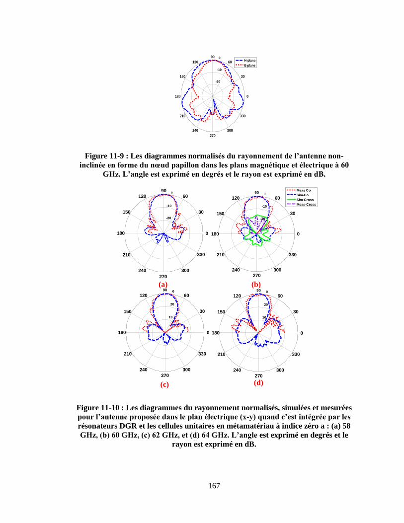
167
Figure 11-9 : Les diagrammes normalisésdurayonnementdel’antennenon-
inclinéeenformedunœudpapillondanslesplansmagnétiqueetélectriqueà60
GHz.L’angleestexpriméendegrésetlerayonestexpriméendB.
-20
-10
0
30
210
60
240
90
270
120
300
150
330
180 0
(a) (b)
10
20
0
30
210
60
240
90
270
120
300
150
330
180 0
10
20
0
30
210
60
240
90
270
120
300
150
330
180 0
(c) (d)
-20
-10
0
30
210
60
240
90
270
120
300
150
330
180 0
Meas Co
Sim-Co
Sim-Cross
Meas-Cross
Figure 11-10 : Les diagrammes du rayonnement normalisés, simulées et mesurées
pourl’antenneproposéedansleplanélectrique(x-y)quandc’estintégréeparles
résonateurs DGR et les cellules unitaires en métamatériau à indice zéro a : (a) 58
GHz,(b)60GHz,(c)62GHz,et(d)64GHz.L’angleest exprimé en degrés et le
rayon est exprimé en dB.
-20
-10
0
30
210
60
240
90
270
120
300
150
330
180 0
H-plane
E-plane
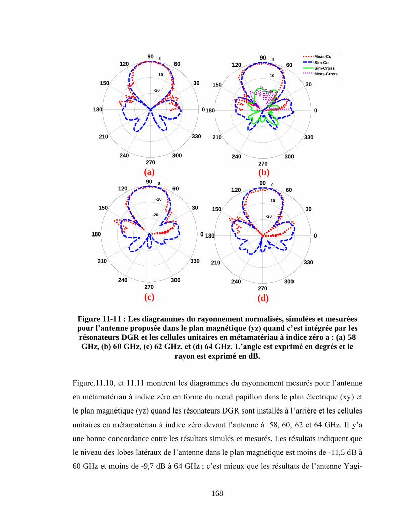
168
-20
-10
0
30
210
60
240
90
270
120
300
150
330
180 0
-20
-10
0
30
210
60
240
90
270
120
300
150
330
180 0
Meas-Co
Sim-Co
Sim-Cross
Meas-Cross
(a) (b)
-20
-10
0
30
210
60
240
90
270
120
300
150
330
180 0
-20
-10
0
30
210
60
240
90
270
120
300
150
330
180 0
(c) (d)
Figure 11-11 : Les diagrammes du rayonnement normalisés, simulées et mesurées
pourl’antenneproposéedansleplanmagnétique(yz)quandc’estintégréeparles
résonateurs DGR et les cellules unitaires en métamatériau à indice zéro a : (a) 58
GHz,(b)60GHz,(c)62GHz,et(d)64GHz.L’angleestexpriméendegrésetle
rayon est exprimé en dB.
Figure.11.10, et 11.11 montrent les diagrammes du rayonnement mesurés pour l‟antenne
en métamatériau à indice zéro en forme du nœud papillon dans le plan électrique (xy) et
le plan magnétique (yz) quand les résonateurs DGR sont installés à l‟arrière et les cellules
unitaires en métamatériau à indice zéro devant l‟antenne à 58, 60, 62 et 64 GHz. Il y‟a
une bonne concordance entre les résultats simulés et mesurés. Les résultats indiquent que
le niveau des lobes latéraux de l‟antenne dans le plan magnétique est moins de -11,5 dB à
60 GHz et moins de -9,7 dB à 64 GHz ; c‟est mieux que les résultats de l‟antenne Yagi-
169
Uda reportés dans l‟article [50] avec un niveau de lobes latéraux de -5 dB ; le niveau du
rayonnement arrière dans les deux plans est supérieur de -20 dB. En outre, la polarisation
croisée de l‟antenne dans le plan électrique (xy) et le plan magnétique (yz) est supérieur
de -17 dB à 60 GHz, c‟est mieux que l‟antenne Vivaldi en métamatériau à ‟indice zéro
dans l‟article [45] avec une polarisation croisée de -10 dB. L‟efficacité de rayonnement
de l‟antenne est 91% à 60 GHz.
11.5 La déviation du faisceau en utilisant un milieu à gradient
d’indicederéfractionpourl’antenneàrayonnement longitudinalà
60 GHz
Dans cette section, on montre les caractéristiques d‟une antenne simple-dipôle utilisant
un milieu métamatériau gradient d‟indice de réfraction. L‟antenne dipôle qu‟on a utilisée
est une version modifiée de l‟antenne dipôle rapportée dans l‟article [50]. Un réseau des
cellules unitaires d‟un milieu à gradient d‟indice de réfraction a été introduit dans le
substrat de l‟antenne et posé devant l‟antenne dipôle dans le plan azimutal, comme le
montre la Figure.11.12. La structure de milieu à gradient d‟indice de réfraction a été
installée afin d‟améliorer le couplage avec le dipôle de sorte à contrôler son rayonnement.
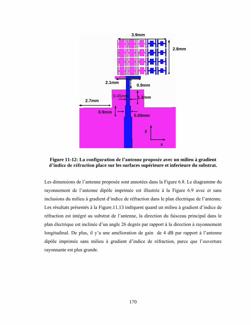
170
2.8mm
3.9mm
2.1mm0.9mm
2.7mm
0.9mm
0.45mm
0.65mm
1.3mm
x
y
Figure 11-12: Laconfigurationdel’antenneproposéeavec un milieu à gradient
d’indicederéfractionplace sur les surfaces supérieure et inferieure du substrat.
Les dimensions de l‟antenne proposée sont annotées dans la Figure 6.8. Le diagramme du
rayonnement de l‟antenne dipôle imprimée est illustrée à la Figure 6.9 avec et sans
inclusions du milieu à gradient d‟indice de réfraction dans le plan électrique de l‟antenne.
Les résultats présentés à la Figure.11.13 indiquent quand un milieu à gradient d‟indice de
réfraction est intégré au substrat de l‟antenne, la direction du faisceau principal dans le
plan électrique est inclinée d‟un angle 26 degrés par rapport à la direction à rayonnement
longitudinal. De plus, il y‟a une amélioration de gain de 4 dB par rapport à l‟antenne
dipôle imprimée sans milieu à gradient d‟indice de réfraction, parce que l‟ouverture
rayonnante est plus grande.
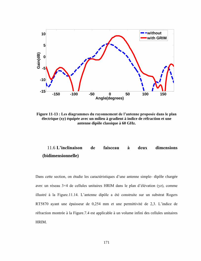
171
Figure 11-13 :Lesdiagrammesdurayonnementdel’antenneproposéedansleplan
électrique (xy) équipée avec un milieu à gradient à indice de réfraction et une
antenne dipôle classique à 60 GHz.
11.6 L’inclinaison de faisceau à deux dimensions
(bidimensionnelle)
Dans cette section, on étudie les caractéristiques d‟une antenne simple- dipôle chargée
avec un réseau 3×4 de cellules unitaires HRIM dans le plan d‟élévation (yz), comme
illustré à la Figure.11.14. L‟antenne dipôle a été construite sur un substrat Rogers
RT5870 ayant une épaisseur de 0,254 mm et une permittivité de 2,3. L‟indice de
réfraction montrée à la Figure.7.4 est applicable à un volume infini des cellules unitaires
HRIM.
-150 -100 -50 0 50 100 150-15
-10
-5
0
5
10
Angle(degrees)
Gain
(dB
)
without
with GRIM
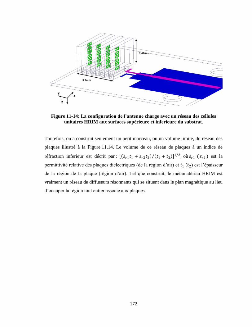
172
Figure 11-14: Laconfigurationdel’antennecharge avec un réseau des cellules
unitaires HRIM aux surfaces supérieure et inferieure du substrat.
Toutefois, on a construit seulement un petit morceau, ou un volume limité, du réseau des
plaques illustré à la Figure.11.14. Le volume de ce réseau de plaques à un indice de
réfraction inferieur est décrit par : 𝜀𝑟1𝑡1 + 𝜀𝑟2𝑡2 𝑡1 + 𝑡2 1 2 , où 𝜀𝑟1 ( 𝜀𝑟2 ) est la
permittivité relative des plaques diélectriques (de la région d‟air) et 𝑡1 (𝑡2) est l‟épaisseur
de la région de la plaque (région d‟air). Tel que construit, le métamatériau HRIM est
vraiment un réseau de diffuseurs résonnants qui se situent dans le plan magnétique au lieu
d‟occuper la région tout entier associé aux plaques.
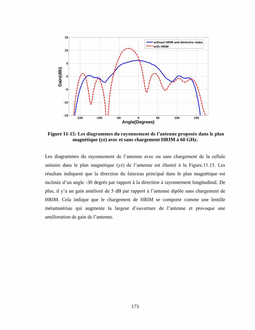
173
Figure 11-15: Lesdiagrammesdurayonnementdel’antenneproposéedansleplan
magnétique (yz) avec et sans chargement HRIM à 60 GHz.
Les diagrammes du rayonnement de l‟antenne avec ou sans chargement de la cellule
unitaire dans le plan magnétique (yz) de l‟antenne est illustré à la Figure.11.15. Les
résultats indiquent que la direction du faisceau principal dans le plan magnétique est
inclinée d‟un angle -30 degrés par rapport à la direction à rayonnement longitudinal. De
plus, il y‟a un gain amélioré de 5 dB par rapport à l‟antenne dipôle sans chargement de
HRIM. Cela indique que le chargement de HRIM se comporte comme une lentille
métamatériau qui augmente la largeur d‟ouverture de l‟antenne et provoque une
amélioration de gain de l‟antenne.
-150 -100 -50 0 50 100 150-15
-10
-5
0
5
10
15
Angle(Degrees)
Gain
(dB
i)
without HRIM and dielectric slabs
with HRIM
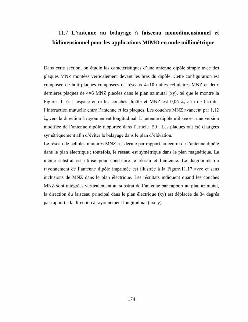
174
11.7 L’antenne au balayage à faisceau monodimensionnel et
bidimensionnel pour les applications MIMO en onde millimétrique
Dans cette section, on étudie les caractéristiques d‟une antenne dipôle simple avec des
plaques MNZ montées verticalement devant les bras du dipôle. Cette configuration est
composée de huit plaques composées de réseaux 4×10 unités cellulaires MNZ et deux
dernières plaques de 4×6 MNZ placées dans le plan azimutal (xy), tel que le montre la
Figure.11.16. L‟espace entre les couches dipôle et MNZ est 0,06 λo afin de faciliter
l‟interaction mutuelle entre l‟antenne et les plaques. Les couches MNZ avancent par 1,12
λo vers la direction à rayonnement longitudinal. L‟antenne dipôle utilisée est une version
modifiée de l‟antenne dipôle rapportée dans l‟article [50]. Les plaques ont été chargées
symétriquement afin d‟éviter le balayage dans le plan d‟élévation.
Le réseau de cellules unitaires MNZ est décalé par rapport au centre de l‟antenne dipôle
dans le plan électrique ; toutefois, le réseau est symétrique dans le plan magnétique. Le
même substrat est utilisé pour construire le réseau et l‟antenne. Le diagramme du
rayonnement de l‟antenne dipôle imprimée est illustrée à la Figure.11.17 avec et sans
inclusions de MNZ dans le plan électrique. Les résultats indiquent quand les couches
MNZ sont intégrées verticalement au substrat de l‟antenne par rapport au plan azimutal,
la direction du faisceau principal dans le plan électrique (xy) est déplacée de 34 degrés
par rapport à la direction à rayonnement longitudinal (axe y).
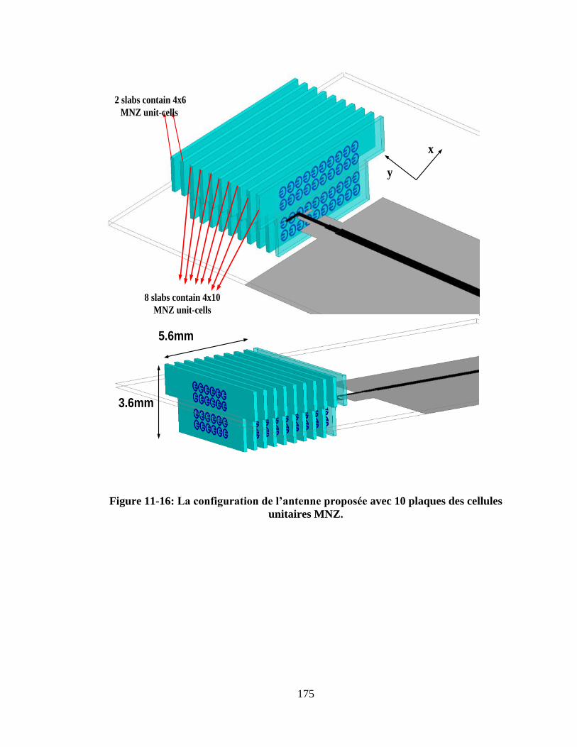
175
x
y
8 slabs contain 4x10
MNZ unit-cells
2 slabs contain 4x6
MNZ unit-cells
5.6mm
3.6mm
Figure 11-16: Laconfigurationdel’antenneproposéeavec 10 plaques des cellules
unitaires MNZ.
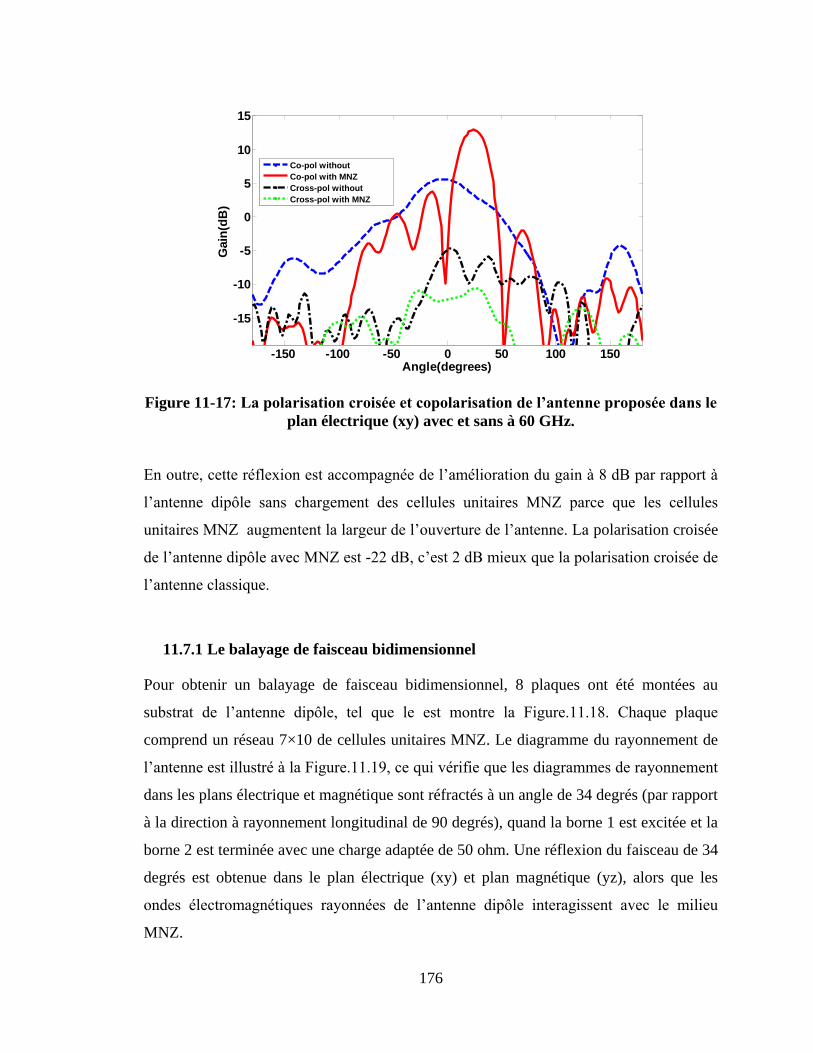
176
Figure 11-17: Lapolarisationcroiséeetcopolarisationdel’antenneproposéedansle
plan électrique (xy) avec et sans à 60 GHz.
En outre, cette réflexion est accompagnée de l‟amélioration du gain à 8 dB par rapport à
l‟antenne dipôle sans chargement des cellules unitaires MNZ parce que les cellules
unitaires MNZ augmentent la largeur de l‟ouverture de l‟antenne. La polarisation croisée
de l‟antenne dipôle avec MNZ est -22 dB, c‟est 2 dB mieux que la polarisation croisée de
l‟antenne classique.
11.7.1 Le balayage de faisceau bidimensionnel
Pour obtenir un balayage de faisceau bidimensionnel, 8 plaques ont été montées au
substrat de l‟antenne dipôle, tel que le est montre la Figure.11.18. Chaque plaque
comprend un réseau 7×10 de cellules unitaires MNZ. Le diagramme du rayonnement de
l‟antenne est illustré à la Figure.11.19, ce qui vérifie que les diagrammes de rayonnement
dans les plans électrique et magnétique sont réfractés à un angle de 34 degrés (par rapport
à la direction à rayonnement longitudinal de 90 degrés), quand la borne 1 est excitée et la
borne 2 est terminée avec une charge adaptée de 50 ohm. Une réflexion du faisceau de 34
degrés est obtenue dans le plan électrique (xy) et plan magnétique (yz), alors que les
ondes électromagnétiques rayonnées de l‟antenne dipôle interagissent avec le milieu
MNZ.
-150 -100 -50 0 50 100 150
-15
-10
-5
0
5
10
15
Angle(degrees)
Gain
(dB
)
Co-pol without
Co-pol with MNZ
Cross-pol without
Cross-pol with MNZ
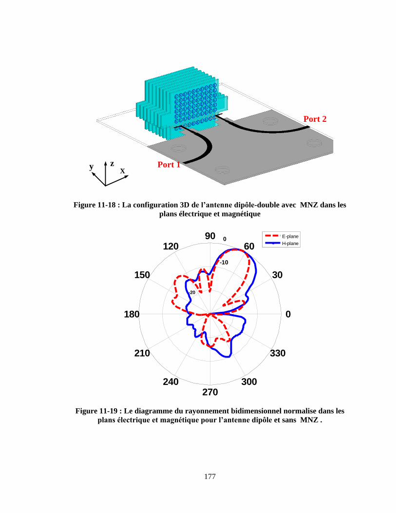
177
Xzy Port 1
Port 2
Figure 11-18 : La configuration 3D del’antennedipôle-double avec MNZ dans les
plans électrique et magnétique
Figure 11-19 : Le diagramme du rayonnement bidimensionnel normalise dans les
plansélectriqueetmagnétiquepourl’antennedipôleet sans MNZ .
-20
-10
0
30
210
60
240
90
270
120
300
150
330
180 0
E-plane
H-plane
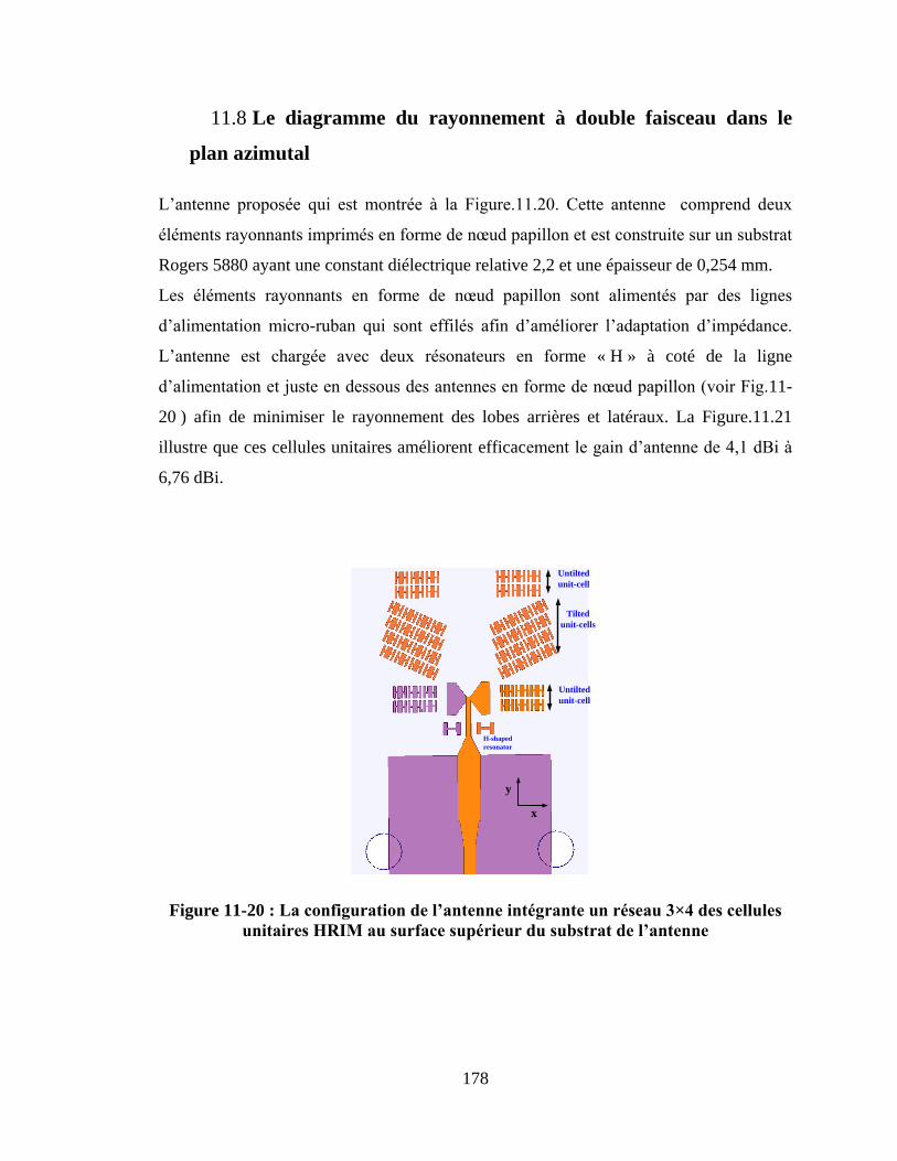
178
11.8 Le diagramme du rayonnement à double faisceau dans le
plan azimutal
L‟antenne proposée qui est montrée à la Figure.11.20. Cette antenne comprend deux
éléments rayonnants imprimés en forme de nœud papillon et est construite sur un substrat
Rogers 5880 ayant une constant diélectrique relative 2,2 et une épaisseur de 0,254 mm.
Les éléments rayonnants en forme de nœud papillon sont alimentés par des lignes
d‟alimentation micro-ruban qui sont effilés afin d‟améliorer l‟adaptation d‟impédance.
L‟antenne est chargée avec deux résonateurs en forme « H » à coté de la ligne
d‟alimentation et juste en dessous des antennes en forme de nœud papillon (voir Fig.11-
20 ) afin de minimiser le rayonnement des lobes arrières et latéraux. La Figure.11.21
illustre que ces cellules unitaires améliorent efficacement le gain d‟antenne de 4,1 dBi à
6,76 dBi.
Tilted
unit-cells
Untilted
unit-cell
Untilted
unit-cell
H-shaped
resonator
x
y
Figure 11-20 :Laconfigurationdel’antenneintégranteunréseau3×4descellules
unitairesHRIMausurfacesupérieurdusubstratdel’antenne
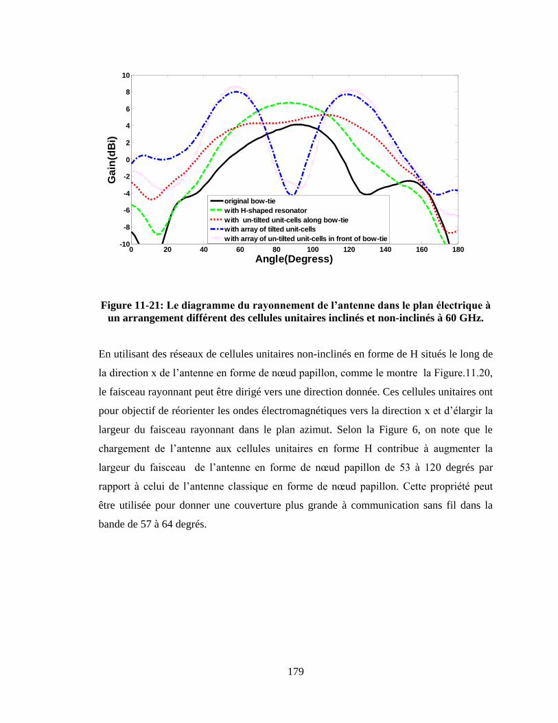
179
0 20 40 60 80 100 120 140 160 180-10
-8
-6
-4
-2
0
2
4
6
8
10
Angle(Degress)
Ga
in(d
Bi)
original bow-tie
with H-shaped resonator
with un-tilted unit-cells along bow-tie
with array of tilted unit-cells
with array of un-tilted unit-cells in front of bow-tie
Figure 11-21: Lediagrammedurayonnementdel’antennedansleplanélectriqueà
un arrangement différent des cellules unitaires inclinés et non-inclinés à 60 GHz.
En utilisant des réseaux de cellules unitaires non-inclinés en forme de H situés le long de
la direction x de l‟antenne en forme de nœud papillon, comme le montre la Figure.11.20,
le faisceau rayonnant peut être dirigé vers une direction donnée. Ces cellules unitaires ont
pour objectif de réorienter les ondes électromagnétiques vers la direction x et d‟élargir la
largeur du faisceau rayonnant dans le plan azimut. Selon la Figure 6, on note que le
chargement de l‟antenne aux cellules unitaires en forme H contribue à augmenter la
largeur du faisceau de l‟antenne en forme de nœud papillon de 53 à 120 degrés par
rapport à celui de l‟antenne classique en forme de nœud papillon. Cette propriété peut
être utilisée pour donner une couverture plus grande à communication sans fil dans la
bande de 57 à 64 degrés.
180
11.9 Conclusion et travaux à venir
Dans le cadre de cette thèse, on a proposé de nouvelles approches pour contrôler
l‟inclinaison de la direction du faisceau principal d‟une antenne à rayonnement
longitudinal dans les plans d‟azimut et d‟élévation utilisant des cellules unitaires en
métasurface et métamatériau. L‟inclinaison de la direction du faisceau principal de
l‟antenne pourrait avoir des applications dans les stations de base des communications
mobiles à contrôler la couverture des cellules plus petites de façon à accroitre la capacité
du système. Les cellules unitaires en métamatériau ont été conçues en utilisant un
nouveau résonateur électrique à ligne de méandre en forme de H. Un réseau de cellules
unitaires en métamatériau a été intégré à une antenne nœud papillon conçue pour
fonctionner de 7 à 8 GHz. Afin d‟obtenir un plus grand angle d‟inclinaison et un gain
élevé, il était nécessaire d‟intégrer un réseau de cellules unitaires 5×4 dans le plan
azimutal. L‟angle d‟inclinaison mesuré a été 17 degrés dans le plan électrique à 7,5 GHz
avec un gain maximal de 9,3 dBi. Les résonateurs à fente annulaire ont été utilisés pour
améliorer l‟angle d‟inclinaison dans le plan d‟élévation de l‟antenne en forme de nœud
papillon. L‟intégration d‟un réseau de résonateurs à fente annulaire non-homogène dans
le plan d‟élévation (plan magnétique) déployé seulement dans les directions y- et z- a
fourni un angle d‟inclinaison de 30 degrés avec une amélioration de gain de 5 dBi à 3,5
GHz. Ces résultats indiquent que l‟approche proposée est convenable pour la prochaine
génération d‟antenne de station de base fonctionnant dans la bande de fréquence
WiMAX. Le niveau des lobes latéraux des diagrammes du rayonnement dans le plan
magnétique est autour de -8 dB. Pour améliorer le niveau des lobes latéraux, c‟est
nécessaire d‟augmenter le nombre des cellules unitaires dans la direction du rayonnement
longitudinal.
La bande de fréquence d‟ondes millimétriques à 60 GHz est nécessaire pour accroitre le
débit de transmission de données plus de 1,5 Gb/s en raison de sa large bande passante
qui s‟étendant de 57 à 64 GHz. Le fonctionnement dans cette bande de fréquences cause
plus de perte d‟affaiblissement (10-16 dB/km) en raison de l‟absorption atmosphérique,
ce qui peut être compensé à l‟aide des réseaux d‟antennes à gain élevé, qui sont
181
complexes et à cout élevé. Pour pallier ce problème, on a proposé dans cette thèse une
nouvelle antenne alimentée par un guide d‟onde intégré au substrat, qui permet d‟opérer à
une large bande de 57 à 64 GHz. Pour l‟amélioration du gain d‟antenne, on a besoin de
(i) incliner les résonateurs en forme de nœud papillon par rapport à la direction du
rayonnement longitudinal, ce qui augmente la taille d‟ouverture de l‟antenne, et par
conséquent son gain ; (ii) charger les résonateurs à fente annulaire sur le coté arrière de
l‟antenne en forme de nœud papillon afin de diriger l‟énergie vers la direction du
rayonnement longitudinal et d‟améliorer le niveau des lobes arrières dans le plan
magnétique ; et (iii) intégrer un réseau des cellules unitaires en métamatériau à indice
zéro devant l‟antenne en forme de nœud papillon pour transformer des ondes sphériques
de l‟antenne en ondes planaires. Le gain d‟antenne mesuré est 12,3 dBi de 57 à 64 GHz.
Une antenne à gain élevé génère un faisceau plus étroit qui rend souvent l‟alignement
difficile entre l‟émetteur et le récepteur. Pour régler ce problème, on a proposé une
approche de formation de faisceau à l‟aide d‟un réseau d‟antennes à commande de phase.
Cette approche consiste à utiliser des résonateurs en forme de H chargés afin d‟altérer la
réponse en phase dans la bande de 57 à 64 GHz. Apres l‟intégration d‟un réseau des
résonateurs en forme de H chargés à une antenne dipôle classique, le faisceau rayonnant
de l‟antenne est dévié dans le plan électrique de 26 degrés. Pour réaliser une
commutation de faisceau, une autre antenne dipôle a été incorporée de l‟autre coté des
cellules unitaires en milieu à gradient d‟indice de réfraction. Par excitation d‟une ligne
d‟alimentation propre à l‟antenne, le faisceau de rayonnement peut être commuté de -26 à
26 degrés. Les résultats de mesures montrent qu‟en utilisant cette technique, le faisceau
de rayonnement peut être balayé de -58 à +58 degrés dans la bande de 57 à 64 GHz. Le
gain d‟antenne au moment du balayage du faisceau est 9,5 dBi à 63 GHz.
Pour obtenir un angle d‟inclinaison plus grand et un gain plus élevé, un réseau des
cellules unitaires à mu-proche de zéro créé par un résonateur à fente annulaire a été
proposé. L‟intégration d‟un réseau des inclusions à mu-proche de zéro à hors-axe de
l‟antenne dipôle dans le plan azimutal et plan d‟élévation a permis d‟obtenir un angle
d‟inclinaison de 35 degrés et un gain élevé de 8dBi. En fait, cette technique indique que
182
le balayage du faisceau bidimensionnel peut être réalisé avec un gain maximal de 14,3
dBi à 60GHz.
L‟antenne à ondes de fuite est une autre technique efficace pour créer un rayonnement à
double faisceaux. En fait, le rayonnement à double faisceaux peut être déployé pour les
applications dans les réseaux locaux sans fil en ondes millimétriques pour améliorer la
qualité de transmission. Toutefois, le rayonnement de l‟antenne à ondes de fuite est
modifié par la fréquence, cela limite son application. Alors, cette thèse propose une
nouvelle technique pour réaliser un rayonnement à double faisceaux avec une antenne à
faisceau fixe opérand dans la bande de 57 à 64 GHz. Ceci a été possible par l‟intégration
d‟un réseau de cellules unitaires en forme de H chargés devant une antenne nœud
papillon. Les résultats indiquent que le faisceau rayonnant dans le plan électrique est
dirigée à +30 et -30 degrés par rapport au rayonnement longitudinal dans la bande de 57 à
64 GHz.
11.9.1 Travaux Futures
Comme indique ci-dessus, l‟inclinaison de faisceau dans le plan azimutal et le plan
d‟élévation peut être réalisée à l‟aide d‟un réseau des cellules unitaires en métasurface et
métamatériau. Pour commuter le faisceau rayonnant, c‟est nécessaire d‟intégrer un
commutateur SP4T à la ligne d‟alimentation. Le commutateur SP4T n‟a pas été utilisé
par la recherche susmentionnée faute de temps, mais c‟était indiqué qu‟on peut l‟ajouter.
Donc, la commutation électronique a besoin d‟être étudiée afin de déterminer la façon
dont le commutateur peut affecter l‟angle d‟inclinaison et les performances de l‟antenne.
En plus, l‟étude paramétrique effectuée indique que l‟augmentation de nombre des
cellules unitaires à la direction voulue conduit à l‟augmentation de l‟angle d‟inclinaison.
Il serait intéressant d‟intégrer les diodes PIN ou varactor aux cellules unitaires pour
contrôler la direction de l‟angle d‟inclinaison et sa largeur de faisceau. Cela permettrait
de développer une antenne dont le diagramme de rayonnement peut être

183
électroniquement reconfiguré dans tous les deux plans. Dans le Chapitre 5, une antenne
en forme de nœud papillon à gain élevé a été appliquée en utilisant d‟une antenne simple
à un gain maximal de 12,3 dBi dans la bande de 57 à 64 GHz. Pour obtenir un gain plus
élevé jusqu‟à 18 dBi, c‟est intéressant de voir comment ca peut être réalisé en utilisant
plusieurs nombres de réseaux.
184
REFRENCES
[1] I. Kim, Y. Rahmat-Samii, “Electromagnetic band gap-dipole sub-array antennas
creating an enhanced tilted beams for future base station,” IET Microw. Antennas
Propag., vol. 9, no. 4, pp. 319–327, 2015.
[2] R.A. Shelby, D.R. Smith, and S. Schultz, “Experimental verification of a negative
index of refraction,” Science, vol. 292, no. 5514, pp.77–79, 2001.
[3] A.Mehdipour, G.V.Eleftheriades, “Leaky-wave antennas using negative refractive
index transmission line metamaterial supercells,” IEEE Trans. Antennas.and
Prpagation., vol.62, no.8, pp. 3929-3942, Feb. 2013.
[4] T. Jiang, Z.Y. Wang, D. Li, J.N. Pan, B. Zhang, “Low-DC voltage controlled
steering-antenna radome utilizing tunable active metamaterial, ” IEEE Trans.
Microw. Theory Tech., vol.61, no.2, pp. 979-985, Feb. 2013
[5] J. R. Costa, E. B. Lima, and C. A. Fernandes, “Compact beam-steerable lens antenna
for 60-GHz wireless communications,” IEEE Trans. Antennas Propag., vol. 57, no.
10, pp. 2926–2933, Oct. 2009
[6] S. Lim, C. Caloz, and T. Itoh, “Metamaterial-based electronically-controlled
transmission line structure as a novel leaky-wave antenna with tunable radiation
angle and beamwidth,” IEEE Trans. Microw. Theory Tech., vol.53, no.1, pp.161-
173, Jan.2005
[7] J.J. Luther, S. Ebadi, and X. Gong, “A Microstrip Patch Electronically Steerable
Parasitic Array Radiator (ESPAR) Antenna With Reactance-Tuned Coupling and
Maintained Resonance,” IEEE Trans. Antennas Propagat., vol.60, no.4, pp.1803-
1813, Sep.2012.
[8] E.R. Brown, “RF-MEMS Switches for Reconfigurable Integrated Circuits,” IEEE
Trans. Microw. Theory Tech., vol.46, no.11, pp.1868-1880, Nov.1998.
[9] J. Huang and A.C. Densmore, “Microstrip Yagi Antenna for Mobile Satellite Vehicle
Application,” IEEE Trans. Antennas Propagat., vol.39, no.7, pp.1024–1030, Jul.
1991.
185
[10] D.F. Filipovic, G.P. Gauthier, S. Raman, and G.M. Rebeiz, “Off-Axis Properties of
Silicon and Quartz Dielectric Lens Antennas,” IEEE Trans. Antennas Propagat.,
vol.45, no.5, pp. 760–766, May 1997.
[11] D-J. Kim and J-H. Lee, “Beam Scanning Leaky-Wave Slot Antenna Using Balanced
CRLH Waveguide Operating above the Cutoff Frequency,” IEEE Trans. Antennas
Propagat., vol.61, no.5, pp. 2432–2440, May 2013.
[12] Marco A. Antoniades, and George V. Eleftheriades, “Multiband Compact Printed
Dipole Antennas Using NRI-TL Metamaterial Loading,” IEEE Trans. Antennas
Propagat., vol.60, no.12, pp. 5613-5626, Dec. 201
[13] D. Li, Z. Szabó, X. Qing, E-P. Li, and Z. Chen, “A High Gain Antenna with an
Optimized Metamaterial Inspired Superstrate,” IEEE Trans. Antennas Propagat.,
vol.60, no.12, pp. 6018-6023, Dec. 2012.
[14] U.C. Hasar, and J.J. Barroso, “Permeability Measurement of Metamaterials with
Split-Ring-Resonators Using Free-Space Calibration-Independent Methods,"
Journal of Infrared, Millimeter, and Terahertz Waves, vol.33, no.2, pp.218-227,
Feb. 2012.
[15] X. Chen, T.M. Grzegorczyk, B.I. Wu, J. Pacheco Jr., and J.A. Kong, "Robust
Method to Retrieve the Constitutive Effective Parameters of Metamaterials," Phys.
Rev. Lett., E 70, 016608, 2004.
[16] C.A. Balanis, Antenna Theory: Analysis and Design, 3rd
ed. Nwe York: Wiley,
2005.
[17] R. Liu, C. Ji, J.J. Mock, J.Y. Chin, T.J. Cui, and D.R. Smith, “Broadband Ground-
Plane Cloak,” Science, vol.323, no.5912, pp.366-369, Jan. 2009.
[18] S.-W. Qu, J.-L. Li, Q. Xue, and C.-H. Chan, “Wideband Periodic End- Fire Antenna
with Bowtie Dipoles,” IEEE Antennas Wireless Propag. Lett., vol.7, pp. 314–317,
2008.
[19] E. Öjefors, S. Cheng, K. From, I. Skarin, P. Hallbjörner, and A. Rydberg,
“Electrically steerable single-layer microstrip traveling wave antenna with varactor
diode based phase shifters,” IEEE Trans. Antennas Propag., vol. 55, no. 9, pp.
2451–2460, Sept. 2007.
186
[20] J. Schoebel et al., “Design considerations and technology assessment of phased-
array antenna systems with RF MEMS for automotive radar applications,” IEEE
Trans. Microw. Theory Tech., vol. 53, no. 6, pp. 1968–1975, Jun. 2005
[21] A. Dadgarpour, B. Zarghooni, B.S. Virdee, T.A. Denidni, “Beam tilting antenna
using integrated metamaterial loading,” IEEE Trans. Antennas Propagat., vol.62,
no.5, pp. 2874-2879, May 2014.
[22] A. Dadgarpour, B. Zarghooni, B.S. Virdee, T.A. Denidni, “Beam deflection using
gradient refractive index media for 60 GHz end-fire antenna,” IEEE Trans.
Antennas Propagat., vol. 63, no.8, pp.3768–3774, Aug. 2015.
[23] A. Dadgarpour, B. Zarghooni, B.S. Virdee, T.A. Denidni,“Improvement of gain and
elevation tilt-angle using metamaterial loading for millimeter-wave applications,”
IEEE Antennas and wireless propagation letters. Early access.
[24] J.D. Baena, L. Jelinek, and R. Marqués, “Towards a systematic design of isotropic
bulk magnetic metamaterials using the cubic point groups of symmetry,” Phys.
Rev. B, vol. 76, no. 24, pp. 245115/1–245115/14, Dec. 2007.
[25] J. Wu, Z. Zhao, Z. Nie, and Q-H. Liu, “Design of a wideband planar printed quasi-
yagi antenna using stepped connection structure,” IEEE Trans. Antennas Propagat.,
vol.62, no.6, pp. 3431-3435, June 2014.
[26] D. Sugimura, M. Arai, K. Sakaguchi, K. Araki, T. Sotoyama, “A study on beam tilt
angle of base station antennas for base station cooperation systems,” IEEE 22nd
International Symposium on Personal Indoor and Mobile Radio Communications,
pp. 2374-2378, 2011.
[27] J.J. Macial, J.F. Slocum, J.K. Smith, J. Turtle, “MEMS electronically steerable
antennas for fire control radars,” Proc. IEEE Radar Conf., pp. 677–682, 2007.
[28] S. Zhang, G.H. Huff, J. Feng, J.T. Bernhard, “A pattern reconfigurable microstrip
parasitic arrays,” IEEE Trans. Antennas Propagat., vol. 52, no.10, pp. 2773–2776,
Oct. 2004.
[29] C-H. Ko, K.M.J. Ho, G.M. Rebeiz, “An electronically-scanned 1.8–2.1 GHz base-
station antenna using packaged high-reliability RFMEMS phase shifters,” IEEE
Trans. Microw. Theory Tech., vol.61, no.2, pp. 979-985, Feb. 2013.
187
[30] C. Pfeiffer and A. Grbic, “A printed, broadband Luneburg lens antenna,” IEEE
Trans. Antennas Propagat., vol. 58, no. 9, pp. 3055–3059, Sep. 2010
[31] L. Xue and V. Fusco, “Patch fed planar dielectric slab waveguide extended
hemielliptical lens antenna,” IEEE Trans. Antennas Propagat., vol. 56, no. 3, pp.
661–666, Mar. 2008.
[32] I. Kim, Y. Rahmat-Samii, “Beam-Tilted Dipole-EBG Array Antenna for Future
Base Station Applications,” IEEE Antennas and propagation society International
Symposium, 2013.
[33] T. Debogović, J. Perruisseau-Carrier, “Array-Fed Partially Reflective Surface
Antenna with Independent Scanning and Beamwidth Dynamic Control,” IEEE
Trans. Antennas Propagat., vol. 62, no. 1, pp. 446–449, Jan. 2014
[34] Z. Szabó, P.G. Ho, R. Hedge, E.P. Li, “A unique extraction of metamaterial
parameters based on Kramers-kronig relationship,” IEEE Trans. Microw. Theory
Tech., vol.58, no.10, pp.2646-2653, Oct.2010
[35] H-L. Wang, Y-X. Guo, W-X. Sheng, “Wideband high-gain 60-GHz LTCC L-probe
patch antenna array with a soft surface," IEEE Trans. Antennas Propagat., vol.61,
no.1, pp.153-161, Jan.2013.
[36] H.Chu, Y-X Guo, Z.Wang, “60-GHz LTCC wideband vertical off-center dipole
antenna and arrays," IEEE Trans. Antennas Propagat., vol.61, no.1, pp.153-161,
Jan.2013.
[37] K. Gong, Z.N. Chen, X. Qing, P. Chen, W. Hong, “Substrate integrated waveguide
cavity-backed wide slot antenna for 60-GHz bands,” IEEE Trans. Antennas
Propagat., vol.60, no.12, pp.6023-6026, Dec.2012.
[38] S.B. Yeap, Z.N. Chen, X. Qing, “Gain-enhanced 60-GHz LTCC antenna array with
open air cavities,” IEEE Trans. Antennas Propag.,vol.59, no.9, pp.3470–3473, Sep.
2011.
[39] Y. She, R. Fujino, J. Hirokawa, M. Ando, D. Hanatani, M. Fujimoto, “LTCC
oversized rectangular waveguide slot array antenna with air-layer in the radiating
part in the millimeter-wave band,” IEEE Trans. Antennas Propag.,vol.61, no.4,
pp.1777–1783, April. 2013.
188
[40] J. Xu, Z.N.Chen, X.Qing, W.Hong, “Bandwidth enhancement for a 60 GHz
substrate integrated waveguide fed cavity array antenna on LTCC,” IEEE Trans.
Antennas Propag., vol.59, no.3, pp.826–832, March. 2011.
[41] K-S. Chin, W. Jiang, W. Che, C-C. Chang, H. Jin, “Wideband LTCC 60-GHz
antenna array with a dual-resonant slot and patch structure,” IEEE Trans. Ant.
Propagat., vol. 62, no. 1, pp. 174-182, Jan. 2014.
[42] D. Wang, K.B. Ng, C.H. Chan, H. Wong, “A novel wideband differentially-fed
higher-order mode millimetre-wave patch antenna,” IEEE Trans. Antenna
Propagat., vol. 63, no. 2, pp. 174-182, Feb. 2015.
[43] Y. Li, Z.N. Chen, X. Qing, Z. Zhang, J. Xu, Z. Feng, “Axial ratio bandwidth
enhancement of 60-GHz substrate integrated waveguide-fed circularly polarized
LTCC antenna array,” IEEE Trans. Antennas Propagat., vol. 60, no. 10, pp. 4619-
4626, Oct. 2012.
[44] M.J.Al-Hasan,T.A.Denidni, A.R.Sebak, “Millimeter-wave EBG-based aperture-
coupled dielectric resonator antenna,” IEEE Trans. Antennas Propagat., vol.61,
no.8, pp.4354-4357, August 2013.
[45] M. Sun, Z.N. Chen,X.Qing, “Gain enhancement of 60-GHz antipodal tapered slot
antenna using zero-index metamaterial,” IEEE Trans. Antennas Propagation.,
vol.61, no.4, pp.1741–1746, April 2013
[46] G.H. Zhai,W. Hong, K. Wu, Z.Q. Kuai, “Wideband substrate integrated printed log-
periodic dipole array antenna,” IET Microwave Antennas Propagat., vol.61, no.6,
pp.3009-3016, Feb 2010.
[47] R. Marqués, F. Mesa, J. Martel, and F. Medina, “Comparative analysis of edge- and
broadside-coupled split ring resonators for metamaterial design-theory and
experiments,” IEEE Trans. Antennas Propag., vol. 51, no. 10, pp. 2572–2581, Oct.
2003
[48] R. Liu, A. Degrion, J.J. Mock, and D.R. Smith, “Negative index material composed
of electric and magnetic resonators,” Appl.Phys.Lett.,vol. 90, no. 26, Jun. 2007.
[49] X. Chen, T.M. Grzegorczyk, B.I. Wu, J. Pacheco Jr., J.A. Kong, “Robust method to
retrieve the constitutive effective parameters of metamaterials,” Phys. Rev. Lett., E
70, 016608, 2004.
189
[50] R.A. Alhalabi, G.M. Rebeiz, “High-gain Yagi-Uda antennas for millimeter-wave
switched-beam systems,” IEEE Trans. Antennas Propagat., vol.57, no.11, pp.3672-
3676, Nov. 2009.
[51] N. Celik, M.F. Iskander, R. Emrick, S.J. Franson, J. Holmes, “Implementation and
experimental verification of a smart antenna system operating at 60 GHz band,”
IEEE Trans. Antennas Propag., vol.56, no.9, pp.2790-2800, Sep. 2008.
[52] G. Grosskopf, R. Eggemann, H. Ehlers, A. Kortke, et al., “Maximum directivity
beam-former at 60 GHz with optical feeder,” IEEE Trans. Antennas Propag.,
vol.51, no.11, pp.3040-3046, Nov. 2003.
[53] P. Deo, D. Mirshekar-Syahkal, L. Seddon, S.E. Day, F.A. Fernández, “60 GHz
liquid crystal phased array using reflection-type phase shifter,” European conf. on
Antennas and Propag., pp. 927-929, April 2013.
[54] C-H. Tseng, C-J. Chen, T-H. Chu, “Alow-cost 60-GHz switched-beam patch
antenna array with butler matrix network,” IEEE Antennas and Wireless
Propagation Letters, vol.7, pp.432-435, 2008.
[55] H. Chu, Y-X. Guo, Z. Wang “60-GHz LTCC wideband vertical off-center dipole
antenna and arrays,” IEEE Trans. Antennas Propagat., vol.61, no.1, pp.153-161,
Jan. 2013.
[56] W.F. Moulder, W. Khalil, J.L. Volakis, “60-GHz two-dimensionally scanning array
employing wideband planar,” IEEE Antennas and Wireless propagation letters,
vol.9, pp.818-821, 2010.
[57] Md. R. Islam, and M. Ali, “A 900 MHz beam steering parasitic antenna array for
wearable wireless applications,” IEEE Trans. Antennas Propag., vol. 61, no. 9,
pp.4520-4527, Sept. 2013.
[58] A. Artemenko, A. Maltsev, A. Mozharovskiy, A. Sevastyanov, V. Ssorin, R.
Maslennikov, “Millimeter-wave electronically steerable integrated lens antennas
for WLAN/WPAN applications,” IEEE Trans. Antennas propagat., vol.61, no.4,
pp. 1665-1671, Apr. 2013.
190
[59] D.F. Filipovic, G.P. Gauthier, S. Raman, and G.M. Rebeiz, “Off-axis properties of
silicon and quartz dielectric lens antennas,” IEEE Trans. Antennas Propag., vol. 45,
no. 5, pp. 760–766, May 1997.
[60] A.J. Guntapalli, T. Dejerafi, K. Wu, “Two dimensional scanning antenna array
driven by integrated waveguide phase shifter,” IEEE Trans. Antennas Propagat.,
vol.62, no.3, pp. 1117-1123, March 2014.
[61] N. Yu, P. Genevet, M.A. Kats, F. Aieta, J.P. Tetienne, et al., “Light propagation
with phase discontinuities: Generalized laws of reflection and refraction,” Science,
vol. 334, pp. 333-337, Oct. 2011.
[62] A.Dadgarpour, B.Zarghooni, B. S.Virdee, T. A.Denidni, “Millimeter-Wave High-
Gain SIW End-Fire Bow-tie Antenna,” IEEE Trans. on Antennas and Propagation,
vol. 63, No. 5, pp. 2337-2342, May. 2015.
[63] K. Hosoya, N. Prasad, K. Ramachandran, N. Orihashi, S. Kishimoto, S. Rampath, K.
Maruhashi, “Multiple sector ID capture (MIDC): A Novel beamforming technique
for 60 GHz band multi-Gbps WLAN/PAN systems,” IEEE Trans. on Antennas and
Propagation, vol. 63, No. 1, pp. 81-96, Dec. 2014.
[64] A. Artemenko, A. Maltsev, R. Maslennikov, A. Sevastyanov, V. Ssorin, “Beam
steerable quartz integrated lens antenna for 60 GHz frequency band,” European
Conference on Antennas and Propagation, pp. 758- 762, 2011.
[65] G. M. Rebeiz, “Millimeter-wave and terahertz integrated circuit antennas,” Proc.
IEEE, vol. 80, no. 11, pp. 1748–1770, Nov. 1992.
[66] Y.J. Cheng, W. Hong, K. Wu, “Millimeter-wave multibeam antenna based on eight-
port hybrid,” IEEE Microwave and Wireless components letters, vol.19, no.4, pp.
212-214, Apr 2009.
[67] A.B.Guntupalli,Ke Wu, “Phase-steered fixed beams in one and two-dimensional
scan space for substrate-integrated radar and radio systems at 60 GHz,” IET
Microwaves, Antennas&propagation. vol.8, no.11, pp. 819-828, Mar. 2014.
[68] H. Tanaka, T. Ohira, “A single-planar integrated self-heterodyne receiver with a
built-in beam steerable array antenna for 60-GHz-band video transmission
systems,” IEEE MTT-S Int. Microw. Symp.Dig.J., vol.2, pp. 735–738, June 2004
191
[69] C.E. Patterson, W.T. Khan, G.E. Ponchak, G.S. May, J. Papapolymerou, “A 60-
GHz active receiving switched-beam antenna array with integrated butler matrix
and GaAs amplifiers,” IEEE Trans. Microw. Theory Tech., vol.60, no.11, pp. 3599-
3607, Nov. 2012.
[70] H. Chu, Y-X. Guo, Z. Wang “60-GHz LTCC wideband vertical off-center dipole
antenna and arrays,” IEEE Trans. Antennas Propagat., vol.61, no.1, pp. 153-161,
Jan. 2013.
[71] Y.J. Cheng, X.Y. Bao, Y.X. Guo “60-GHz LTCC miniaturized substrate integrated
multibeam array antenna with multiple polarizations,” IEEE Trans. Antennas
Propagat., vol.61, no.12, pp. 5958-5967, Dec. 2013.
[72] A. Dadgarpour, B. Zarghooni, B.S. Virdee, T.A. Denidni, “Enhancement of Tilted-
beam in Elevation Plane for Planar End-Fire Antennas using Artificial Dielectric
Medium,” accepted by IEEE Trans. Antennas Propagat.
[73] X. Wu, G. V. Eleftheriades, and T. E. van Deventer-Perkins, “Design and
characterization of a single- and multiple-beam millimeter-wave circularly
polarized substrate lens antennas for wireless communications,” IEE
[74] O. Lafond, M. Himdi, H. Merlet, P. Lebars, “An active reconfigurable antenna at 60
GHz Based on plate Inhomogeneous lens and feeders,” IEEE Trans. Antennas
propagat., vol.61, no.4, pp. 1672-1678, Apr. 2013
[75] B. Schoenlinner, X. Wu, J. P. Ebling, G. V. Eleftheriades, and G. M. Rebeiz, “Wide-
scan spherical-lens antennas for automotive radars,” IEEE Trans. Microw. Theory
Tech., vol. 50, no. 9, pp. 2166–2175, Sep. 2002
[76] A.B.Guntupalli, T. Djerafi, Ke Wu, “Two-dimensional scanning antenna array
driven by integrated waveguide phase shifter,” IEEE Trans. Antennas propagat.,
vol.62, no.3, pp. 1117-1123, Mar. 201
[77] W. Choi, K. Park, Y. Kim, K. Kim,Y. Kwon, “A V-band switched beam-forming
antenna module using absorptive switch integrated with 4×4 butler matrix in 0.13-
μm CMOS,” IEEE Trans. Microw. Theory Tech., vol.58, no.12, pp. 4052-4059,
Dec. 2010.
192
[78] W. Hong, A. Goudelev,K-H. Baek, V.A. Rkhipenkov, J. Lee, “24-element antenna-
in-package for stationary 60-GHz communication scenarios,” IEEE Microwave and
Wireless components letters, vol.21, no.3, pp.142-144, March2011
[79] Y. Li, M.F. Iskander, Z. Zhang, Z. Feng, “A new low cost leaky wave coplanar
waveguide continuous transverse stub antenna array using metamaterial-based
phase shifters for beam steering,” IEEE Trans. Antennas propagat., vol.61, no.7,
pp. 3511-3518, July. 2013
[80] H. Attia, L. Yousefi, M.M. Bait-Suwailam, M.S. Boybay, O.M. Ramahi, “Enhanced-
gain microstrip antenna using engineered magnetic superstrates,” IEEE Ant. and
Wireless Propag. Letters, vol.8, no., pp.1198-1201, 2009
[81] J.P. Turpin, Q. Wu, D.H. Werner, B. Martin, M. Bray, and E. Lier, “Low cost and
broadband dual-polarization metamaterial lens for directivity enhancement,” IEEE
Trans. Antennas Propag., vol. 60, no. 12, pp. 5717-5726, Dec. 2012.
[82] A. Erentok, P. L. Luljak, and R. W. Ziolkowski, “Characterization of a volumetric
metamaterial realization of an artificial magnetic conductor for antenna
applications,” IEEE Trans. Antennas Propag., vol. 53, pp. 160–172, Jan. 2005.
[83] K. Li, M. Ingram, and E. Rausch, “Multi beam antennas for indoor wireless
communications,” IEEE Trans. Comm., vol. 50, no. 2, Feb. 2002.
[84] R.A. Alhalabi, Y.-C. Chiou, and G. M. Rebeiz, “Self-shielded high-efficiency Yagi-
Uda antennas for 60 GHz communications,” IEEE Trans. Antennas Propag., vol.
59, no. 3, pp. 742–750, 2011
[85] S. Jafarlou, M. Bakri-Kassem, M. Fakharzadeh, Z. Sotoodeh, S. Safavi-Naeini, “A
wideband CPW-fed planar dielectric tapered antenna with parasitic elements for
60-GHz integrated application,” IEEE Trans. Antennas Propag., vol. 62, no. 12,
pp. 6010–6018, Dec 2014.
[86] A. Dadgarpour, B. Zarghooni, B.S. Virdee, T.A. Denidni,“Improvement of gain and
elevation tilt-angle using metamaterial loading for millimeter-wave applications,”
IEEE Antennas and Wireless Propagation Letters. Early access.
[87] A. Dadgarpour, B. Zarghooni, B.S. Virdee, T.A. Denidni, “High gain end-fire bow-
tie antenna using artificial dielectric layers,” IET Microw. Antennas Propag., May
2015.
193
[88] S-G. Kim and K. Chang, “Independently controllable dual-feed dual-beam phased
array using piezoelectric transducers,” IEEE Antennas and Wireless Propagation
Letters. vol.1, pp.81–83, 2002.
[89] A. Mehdipour and G.V. Eleftheriades, “Leakywave antennas using negative
refractive-index transmission-line (NRI-TL) metamaterial supercells”, IEEE Trans.
Antennas Propag., DOI 10.1109/TAP.2014.2322882.
[90] A. Mehdipour, J.W. Wong, and G.V. Eleftheriades, “Beam-squinting reduction of
leaky-wave antennas using Huygens metasurfaces,” IEEE Trans. Antennas Propag.,
vol. 63, no. 3, pp. 978–992, March. 2015.
[91] W. Cao, W. Hong, Z.N. Chen, B. Zhang, and A. Liu, “Gain enhancement of beam
scanning substrate integrated waveguide slot array antennas using a phase-
correcting grating cover,” IEEE Trans. Antennas Propagat., vol.62, no.9, pp. 4584–
4591, Sep. 2014
[92] T-L. Chen and Y-D. Lin, “Dual-beam microstrip leaky-wave array excited by
aperture-coupling method,” IEEE Trans. Antennas Propagat., vol.51, no.9, pp.
2496–2498, Sep. 2003
[93] Z.L. Ma and L.J. Jiang, “One-dimensional triple periodic dual-beam microstrip
leaky-wave antenna,” IEEE Antennas and Wireless Propagation Letters. vol.14,
2015
[94] C-C. Hu, C.F. Jou, and J-J. Wu “An aperture-coupled linear microstrip leaky-wave
antenna array with two-dimensional dual-beam scanning capability,” IEEE Trans.
Antennas Propag., vol. 48, no.6, pp. 909–913, Jun. 2000.
[95] A. Khidre, K-F. Lee, A.Z. Elsherbeni, and F. Yang, “Wide band dual-beam u-slot
microstrip antenna,” IEEE Trans. Antennas Propagat., vol.61, no.3, pp. 1415-1418,
March. 2013.
[96] A. Amadjikpe, D. Choudhury, C. Patterson, B. Lacroix, G. Ponchak, and J.
Papapolymerou, “Integrated 60-GHz antenna on multilayer organic package with
broadside and end-fire radiation,” IEEE Trans. Microw. Theory Tech., vol. 61, no.
1, pp. 303–315, Jan. 2013.
194
[97] K.M.K.H. Leong, Y. Qian, and T. Itoh, “Surface wave enhanced broadband planar
antenna for wireless applications,” IEEE Microw. Wireless Compon. Lett., vol. 11,
no. 2, pp. 62–64, Feb. 2001.
[98] N.G. Alexopoulos, P.B. Katehi, and D.B. Rutledge, “Substrate optimization for
integrated circuit antennas,” IEEE Trans. Microw. Theory Techn., vol. MTT-31,
no. 7, pp. 550–557, Jul. 1983.