Embed Size (px)
Citation preview

8/13/2019 Arriel_2B-2B1 11-02 En
http://slidepdf.com/reader/full/arriel2b-2b1-11-02-en 1/461
ARRIEL 2B 2B1RRIEL 2B 2B1
TURBOSHAFT
ENGINE
Training manualNovember 2002
Ref.: X292 M5 960 2
8/13/2019 Arriel_2B-2B1 11-02 En
http://slidepdf.com/reader/full/arriel2b-2b1-11-02-en 2/461
Training Manual ARR
FOREWORD
This document provides, in a teaching form, all the in
required for the operation and the maintenance of the
2B - 2B1 Turboshaft engine for training purposes only
It will not be updated, and if required, modificatio
included in a new issue.
TURBOMECA T
8/13/2019 Arriel_2B-2B1 11-02 En
http://slidepdf.com/reader/full/arriel2b-2b1-11-02-en 3/461
Training Manual ARR
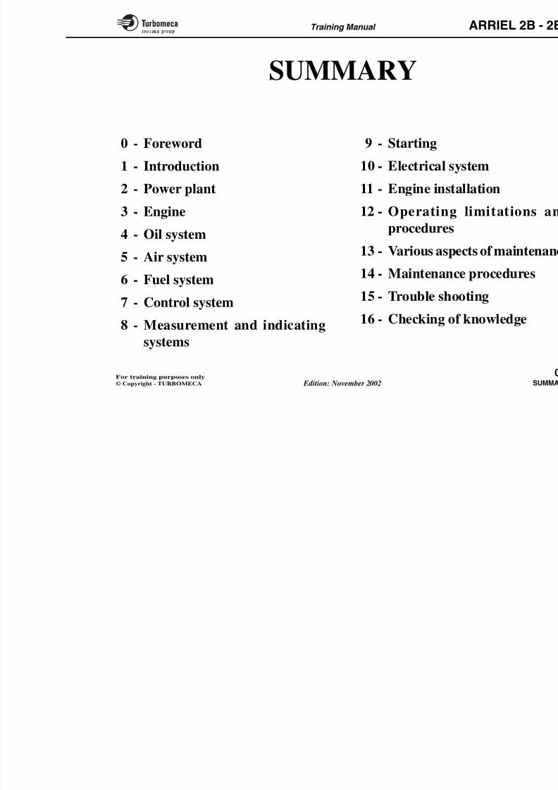
SUMMARY
0 - Foreword1 - Introduction
2 - Power plant
3 - Engine
4 - Oil system
5 - Air system
6 - Fuel system
7 - Control system
8 - Measurement and indicating
9 - Starting10 - Electrical system
11 - Engine installation
12 - Operating limit
procedures
13 - Various aspects of
14 - Maintenance proc
15 - Trouble shooting16 - Checking of know
8/13/2019 Arriel_2B-2B1 11-02 En
http://slidepdf.com/reader/full/arriel2b-2b1-11-02-en 4/461
Training Manual ARR
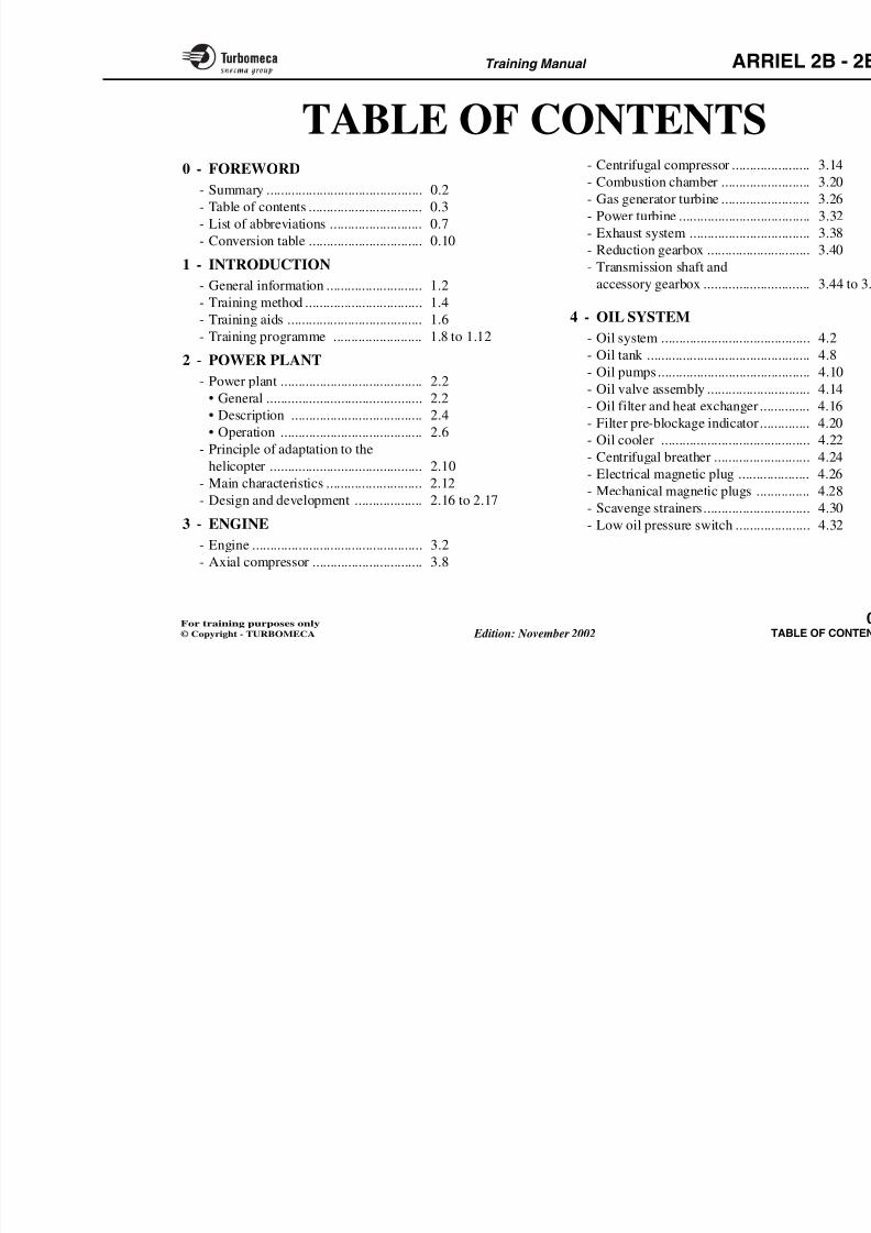
TABLE OF CONTENTS0 - FOREWORD
- Summary ............................................ 0.2
- Table of contents ................................ 0.3
- List of abbreviations .......................... 0.7
- Conversion table ................................ 0.10
1 - INTRODUCTION
- General information ........................... 1.2
- Training method ................................. 1.4
- Training aids ...................................... 1.6
- Training programme ......................... 1.8 to 1.12
2 - POWER PLANT
- Power plant ........................................ 2.2
• General ............................................ 2.2
• Description ..................................... 2.4
• Operation ........................................ 2.6
- Principle of adaptation to the
helicopter ........................................... 2.10- Main characteristics ........................... 2.12
- Design and development ................... 2.16 to 2.17
- Centrifugal compressor ...........
- Combustion chamber ..............
- Gas generator turbine ..............
- Power turbine ..........................
- Exhaust system .......................- Reduction gearbox ..................
- Transmission shaft and
accessory gearbox ...................
4 - OIL SYSTEM
- Oil system ...............................
- Oil tank ...................................- Oil pumps................................
- Oil valve assembly ..................
- Oil filter and heat exchanger ...
- Filter pre-blockage indicator...
- Oil cooler ...............................
- Centrifugal breather ................
- Electrical magnetic plug .........
- Mechanical magnetic plugs ....
- Scavenge strainers...................
8/13/2019 Arriel_2B-2B1 11-02 En
http://slidepdf.com/reader/full/arriel2b-2b1-11-02-en 5/461
Training Manual ARR
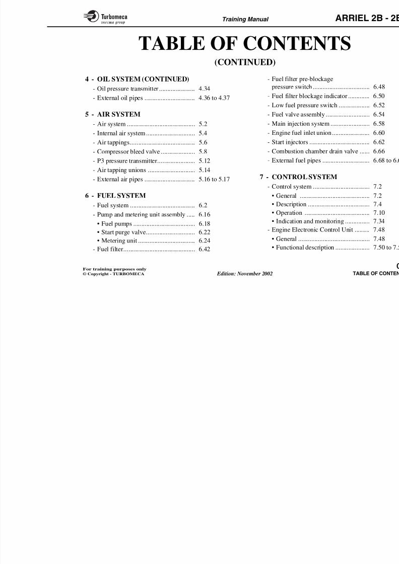
TABLE OF CONTENTS(CONTINUED)
4 - OIL SYSTEM (CONTINUED)
- Oil pressure transmitter ...................... 4.34
- External oil pipes ............................... 4.36 to 4.37
5 - AIR SYSTEM
- Air system .......................................... 5.2
- Internal air system .............................. 5.4
- Air tappings........................................ 5.6
- Compressor bleed valve ..................... 5.8
- P3 pressure transmitter....................... 5.12- Air tapping unions ............................. 5.14
- External air pipes ............................... 5.16 to 5.17
6 - FUEL SYSTEM
- Fuel system ........................................ 6.2
- Pump and metering unit assembly ..... 6.16• Fuel pumps ...................................... 6.18
• Start purge valve.............................. 6.22
- Fuel filter pre-blockage
pressure switch .........................
- Fuel filter blockage indicator ...
- Low fuel pressure switch .........- Fuel valve assembly .................
- Main injection system ..............
- Engine fuel inlet union.............
- Start injectors ...........................
- Combustion chamber drain valv
- External fuel pipes ...................
7 - CONTROL SYSTEM
- Control system .........................
• General .................................
• Description ............................
• Operation ..............................• Indication and monitoring .....
- Engine Electronic Control Unit
8/13/2019 Arriel_2B-2B1 11-02 En
http://slidepdf.com/reader/full/arriel2b-2b1-11-02-en 6/461
Training Manual ARR
TABLE OF CONTENTS(CONTINUED)
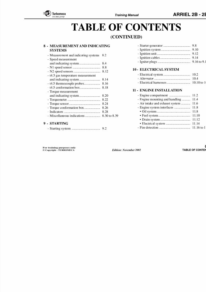
8 - MEASUREMENT AND INDICATING
SYSTEMS
- Measurement and indicating systems 8.2- Speed measurement
and indicating system......................... 8.4
- N1 speed sensor ................................. 8.8
- N2 speed sensors ................................ 8.12
- t4.5 gas temperature measurement
and indicating system......................... 8.14
- t4.5 thermocouple probes................... 8.16- t4.5 conformation box........................ 8.18
- Torque measurement
and indicating system......................... 8.20
- Torquemeter ....................................... 8.22
- Torque sensor ..................................... 8.24
- Torque conformation box ................... 8.26
- Indicators ........................................... 8.28- Miscellaneous indications .................. 8.30 to 8.39
9 STARTING
- Starter-generator ......................
- Ignition system.........................
- Ignition unit ..............................
- Ignition cables ..........................
- Igniter plugs .............................
10 - ELECTRICAL SYSTEM
- Electrical system ......................
- Alternator .................................
- Electrical harnesses ..................
11 - ENGINE INSTALLATION
- Engine compartment ...............
- Engine mounting and handling
- Air intake and exhaust system .
- Engine system interfaces .........
• Oil system..............................• Fuel system............................
• Drain system..........................
8/13/2019 Arriel_2B-2B1 11-02 En
http://slidepdf.com/reader/full/arriel2b-2b1-11-02-en 7/461
Training Manual ARR
TABLE OF CONTENTS(CONTINUED)
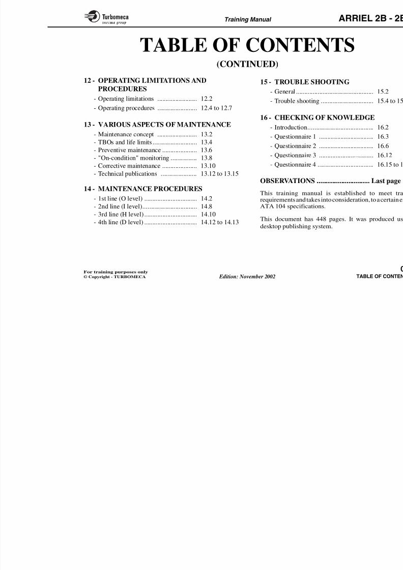
12 - OPERATING LIMITATIONS AND
PROCEDURES
- Operating limitations ........................ 12.2
- Operating procedures ........................ 12.4 to 12.7
13 - VARIOUS ASPECTS OF MAINTENANCE
- Maintenance concept ........................ 13.2
- TBOs and life limits ........................... 13.4
- Preventive maintenance ..................... 13.6
- "On-condition" monitoring ................ 13.8
- Corrective maintenance ..................... 13.10
- Technical publications ...................... 13.12 to 13.15
14 - MAINTENANCE PROCEDURES
- 1st line (O level) ................................ 14.2
- 2nd line (I level)................................. 14.8
- 3rd line (H level) ................................ 14.10- 4th line (D level) ................................ 14.12 to 14.13
15 - TROUBLE SHOOTING
- General .....................................
- Trouble shooting ......................
16 - CHECKING OF KNOWLE
- Introduction..............................
- Questionnaire 1 .......................
- Questionnaire 2 .......................
- Questionnaire 3 .......................
- Questionnaire 4 ........................
OBSERVATIONS .......................
This training manual is establishrequirements and takes into consideraATA 104 specifications.
This document has 448 pages. It w
desktop publishing system.
8/13/2019 Arriel_2B-2B1 11-02 En
http://slidepdf.com/reader/full/arriel2b-2b1-11-02-en 8/461
Training Manual ARR
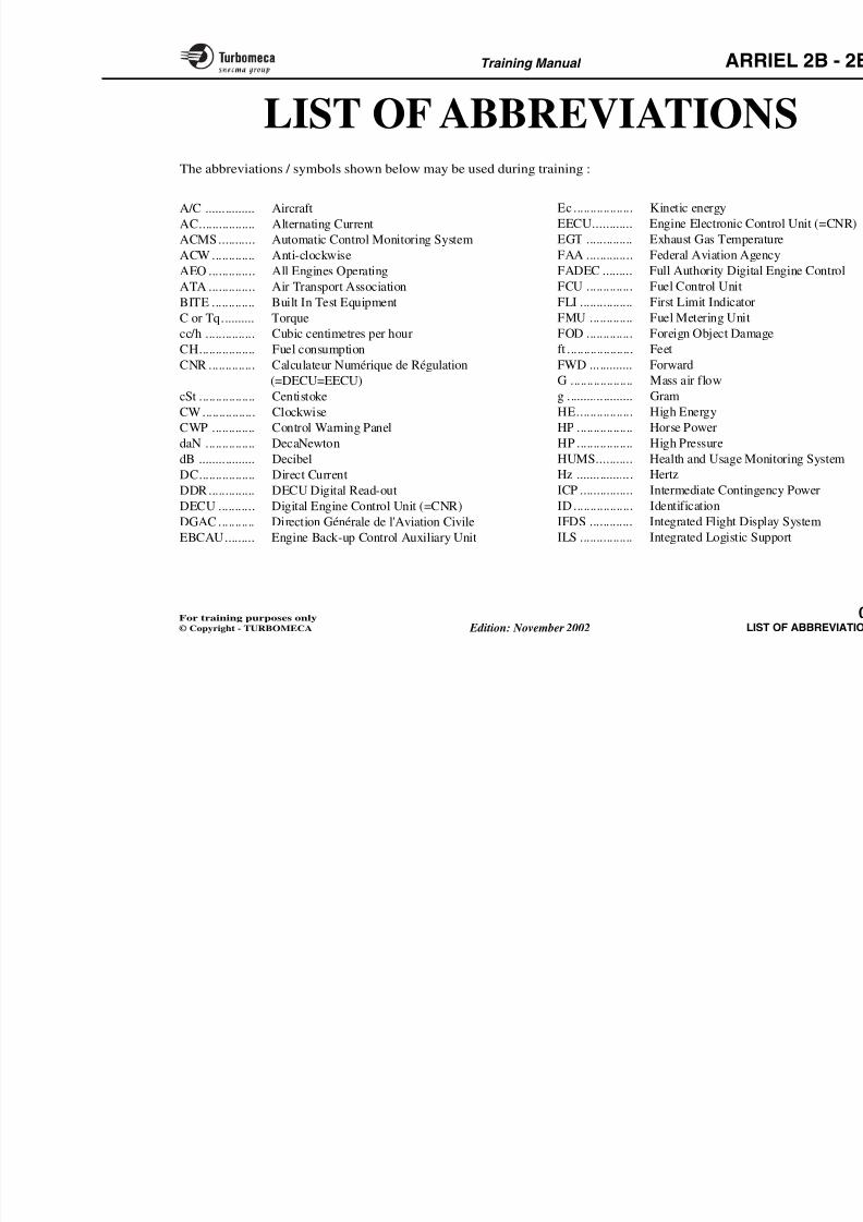
Ec .................. Kinetic energy
EECU............ Engine Electronic Con
EGT .............. Exhaust Gas Tempera
FAA .............. Federal Aviation Agen
FADEC ......... Full Authority Digital
FCU .............. Fuel Control Unit
FLI ................ First Limit Indicator
FMU ............. Fuel Metering Unit
FOD .............. Foreign Object Damag
ft .................... FeetFWD ............. Forward
G ................... Mass air flow
g .................... Gram
HE................. High Energy
HP ................. Horse Power
HP ................. High Pressure
HUMS........... Health and Usage MoHz ................. Hertz
ICP ................ Intermediate Continge
ID .................. Identification
A/C ............... Aircraft
AC................. Alternating Current
ACMS........... Automatic Control Monitoring System
ACW ............. Anti-clockwise
AEO .............. All Engines Operating
ATA .............. Air Transport Association
BITE ............. Built In Test Equipment
C or Tq.......... Torque
cc/h ............... Cubic centimetres per hour
CH................. Fuel consumptionCNR .............. Calculateur Numérique de Régulation
(=DECU=EECU)
cSt ................. Centistoke
CW................ Clockwise
CWP ............. Control Warning Panel
daN ............... DecaNewton
dB ................. DecibelDC................. Direct Current
DDR.............. DECU Digital Read-out
DECU ........... Digital Engine Control Unit (=CNR)
LIST OF ABBREVIATIONThe abbreviations / symbols shown below may be used during training :
8/13/2019 Arriel_2B-2B1 11-02 En
http://slidepdf.com/reader/full/arriel2b-2b1-11-02-en 9/461
Training Manual ARR
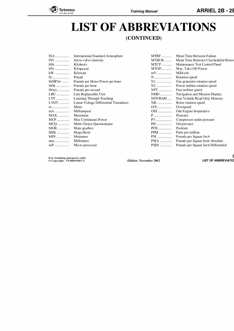
LIST OF ABBREVIATION(CONTINUED)
ISA................ International Standard Atmosphere
ISV................ Servo-valve intensity
kHz ............... Kilohertz
kPa ................ Kilopascal
kW ................ Kilowatt
lb ................... Pound
lb/HP.hr ........ Pounds per Horse Power per hour
lb/hr............... Pounds per hour
lb/sec. ............ Pounds per second
LRU .............. Line Replaceable UnitLTT ............... Learning Through Teaching
LVDT ........... Linear Voltage Differential Transducer
m ................... Metre
mA ................ Milliampere
MAX ............. Maximum
MCP.............. Max Continuous Power
MCQ ............. Multi Choice Questionnaire
MGB ............. Main gearbox
MHz .............. Mega Hertz
MIN .............. Minimum
MTBF ........... Mean Time Between F
MTBUR ........ Mean Time Between U
MTCP ........... Maintenance Test Con
MTOP ........... Max. Take-Off Power
mV ................ Millivolt
N ................... Rotation speed
N1 ................. Gas generator rotation
N2 ................. Power turbine rotation
NFT............... Free turbine speed
NMD ............. Navigation and MissioNOVRAM .... Non Volatile Read On
NR................. Rotor rotation speed
O/S................ Overspeed
OEI ............... One Engine Inoperativ
P .................... Pressure
P3 .................. Compressor outlet pre
PH ................. Oil pressure
POS ............... Position
PPM .............. Parts per million
PSI ................ Pounds per Square Inc
8/13/2019 Arriel_2B-2B1 11-02 En
http://slidepdf.com/reader/full/arriel2b-2b1-11-02-en 10/461
Training Manual ARR
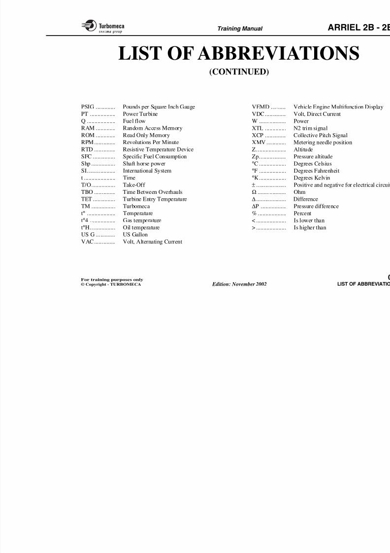
LIST OF ABBREVIATION(CONTINUED)
PSIG ............. Pounds per Square Inch GaugePT ................. Power Turbine
Q ................... Fuel flow
RAM ............. Random Access Memory
ROM ............. Read Only Memory
RPM.............. Revolutions Per Minute
RTD .............. Resistive Temperature Device
SFC ............... Specific Fuel ConsumptionShp ................ Shaft horse power
SI................... International System
t ..................... Time
T/O................ Take-Off
TBO .............. Time Between Overhauls
TET ............... Turbine Entry Temperature
TM ................ Turbomeca
t° ................... Temperature
t°4 ................. Gas temperature
t°H................. Oil temperature
VEMD .......... Vehicle Engine MultifVDC.............. Volt, Direct Current
W .................. Power
XTL .............. N2 trim signal
XCP .............. Collective Pitch Signa
XMV ............. Metering needle posit
Z.................... Altitude
Zp.................. Pressure altitude°C .................. Degrees Celsius
°F .................. Degrees Fahrenheit
°K.................. Degrees Kelvin
± .................... Positive and negative
Ω ................... Ohm
∆.................... Difference
∆P ................. Pressure difference
% ................... Percent
< .................... Is lower than
> .................... Is higher than
8/13/2019 Arriel_2B-2B1 11-02 En
http://slidepdf.com/reader/full/arriel2b-2b1-11-02-en 11/461
Training Manual ARR
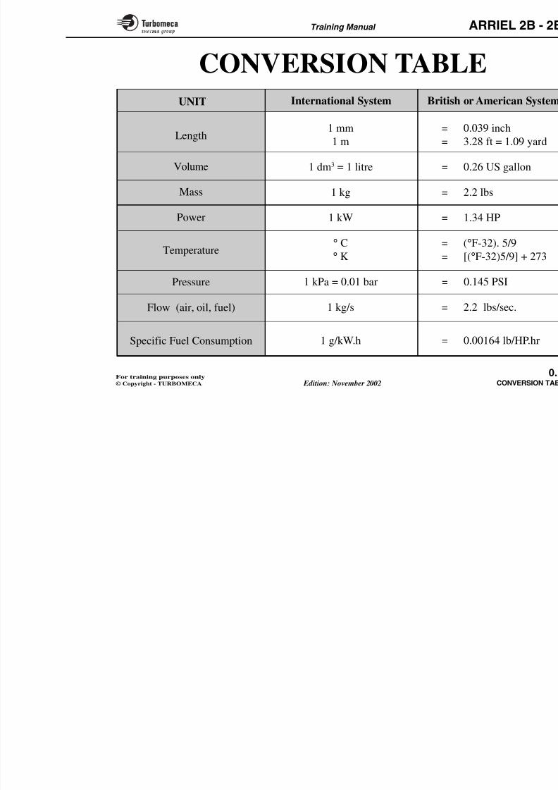
1 mm = 0.039 i
1 m = 3.28 ft
1 dm3 = 1 litre = 0.26 U
1 kg = 2.2 lbs
1 kW = 1.34 H
° C = (°F-32)
° K = [(°F-32
1 kPa = 0.01 bar = 0.145 P
1 kg/s = 2.2 lbs
Length
Volume
Mass
Power
Temperature
Pressure
Flow (air, oil, fuel)
CONVERSION TABLEUNIT International System British or Am
8/13/2019 Arriel_2B-2B1 11-02 En
http://slidepdf.com/reader/full/arriel2b-2b1-11-02-en 12/461
Training Manual ARR
1-INTRODUCTION
- General information...................................................... 1
- Training method ............................................................ 1
- Training aids .................................................................. 1
- Training programme .................................................... 1
8/13/2019 Arriel_2B-2B1 11-02 En
http://slidepdf.com/reader/full/arriel2b-2b1-11-02-en 13/461
Training Manual ARR
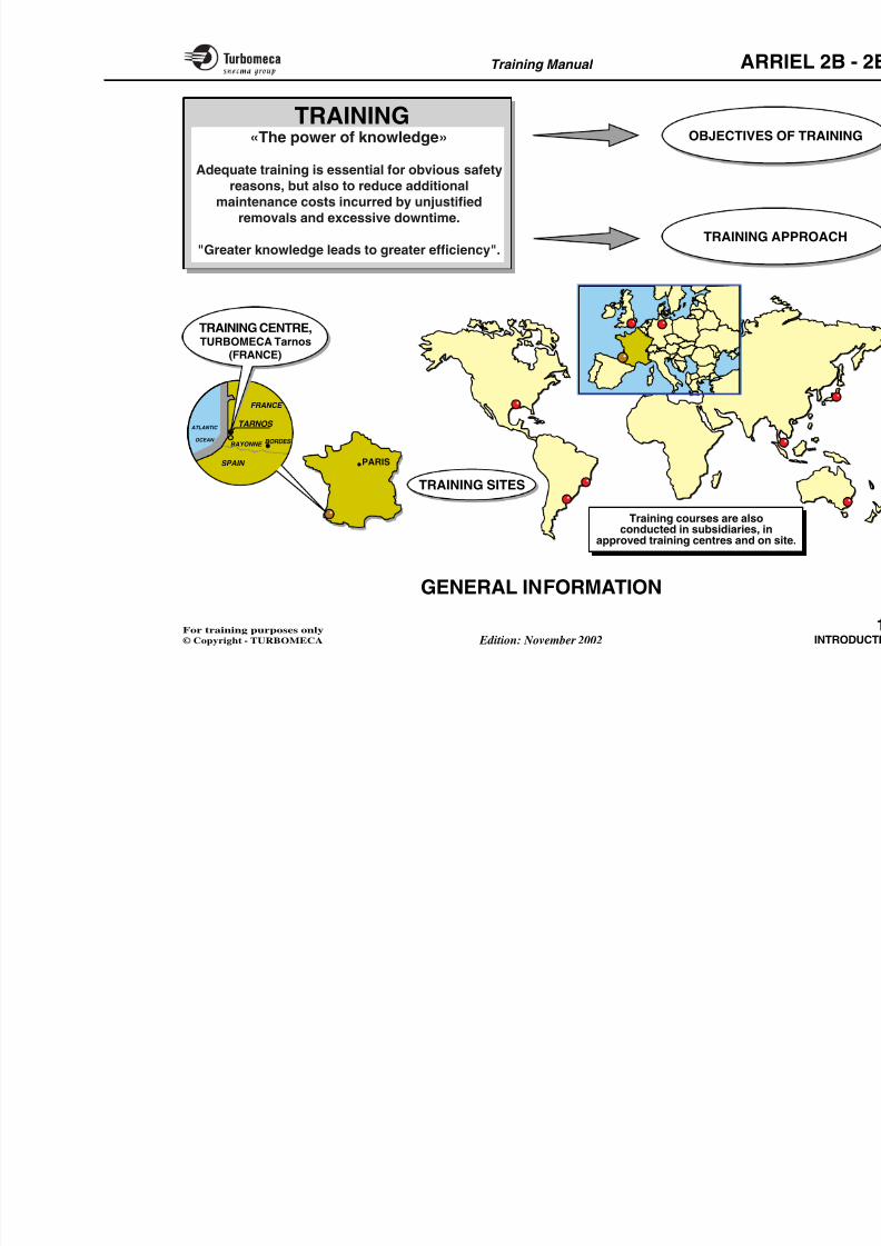
GENERAL INFORMATION
«The power of knowledge»
Adequate training is essential for obvious safety reasons,but also to reduce additional maintenance costs incurredby unjustified removals and excessive downtime.
"Greater knowledge leads to greater efficiency".
Objectives of trainingThe main objective is the acquisition of the knowledgerequired for the tasks to be achieved (know and knowhow).
Further information is also communicated to widen theskill and the experience of the trainee.
Training approach
- Performance based training according to taskanalysis, with classroom sessions, student involvement,practical work and troubleshooting techniques
- Advanced training aids : training manual, ComputerAided Presentation (or overhead projection), multimedia
courseware and demonstration mock-ups
- Experienced and formally trained instructors
Training Centre
The Training Centre is located in onTURBOMECA's TARNOS factory.
TARNOS .... 5 kms north of ANGLET - BIARRIby train (BAYONN(BIARRITZ-PARM(A63 highway, TAR
Address ...... TURBOMECA - FRANCE
Telephone .. (33) 5 59 74 40 07 o
Fax .............. (33) 5 59 74 45 16 o
E-mail ......... training.centre@turb
Web site ..... " T . O . O . L . S " (
OPERATOR ON-Lwww.turbomeca-sup
The training centre is organized intraining demands (administratiinstructors).
Training sites
Training courses are also conducteapproved training centres and on site
- by a TURBOMECA qualified insubsidiaries and approved training
8/13/2019 Arriel_2B-2B1 11-02 En
http://slidepdf.com/reader/full/arriel2b-2b1-11-02-en 14/461
Training Manual ARR
PARIS
TARNOS
BORDES
SPAIN
FRANCE
BAYONNE
ATLANTIC
OCEAN
TRAINING OBJECTIVES O
TRAINING A
«The power of knowledge»
Adequate training is essential for obvious safety
reasons, but also to reduce additional
maintenance costs incurred by unjustified
removals and excessive downtime.
"Greater knowledge leads to greater efficiency".
TRAINING SITES
Training courses are also
TRAINING CENTRE,TURBOMECA Tarnos
(FRANCE)
8/13/2019 Arriel_2B-2B1 11-02 En
http://slidepdf.com/reader/full/arriel2b-2b1-11-02-en 15/461
Training Manual ARR
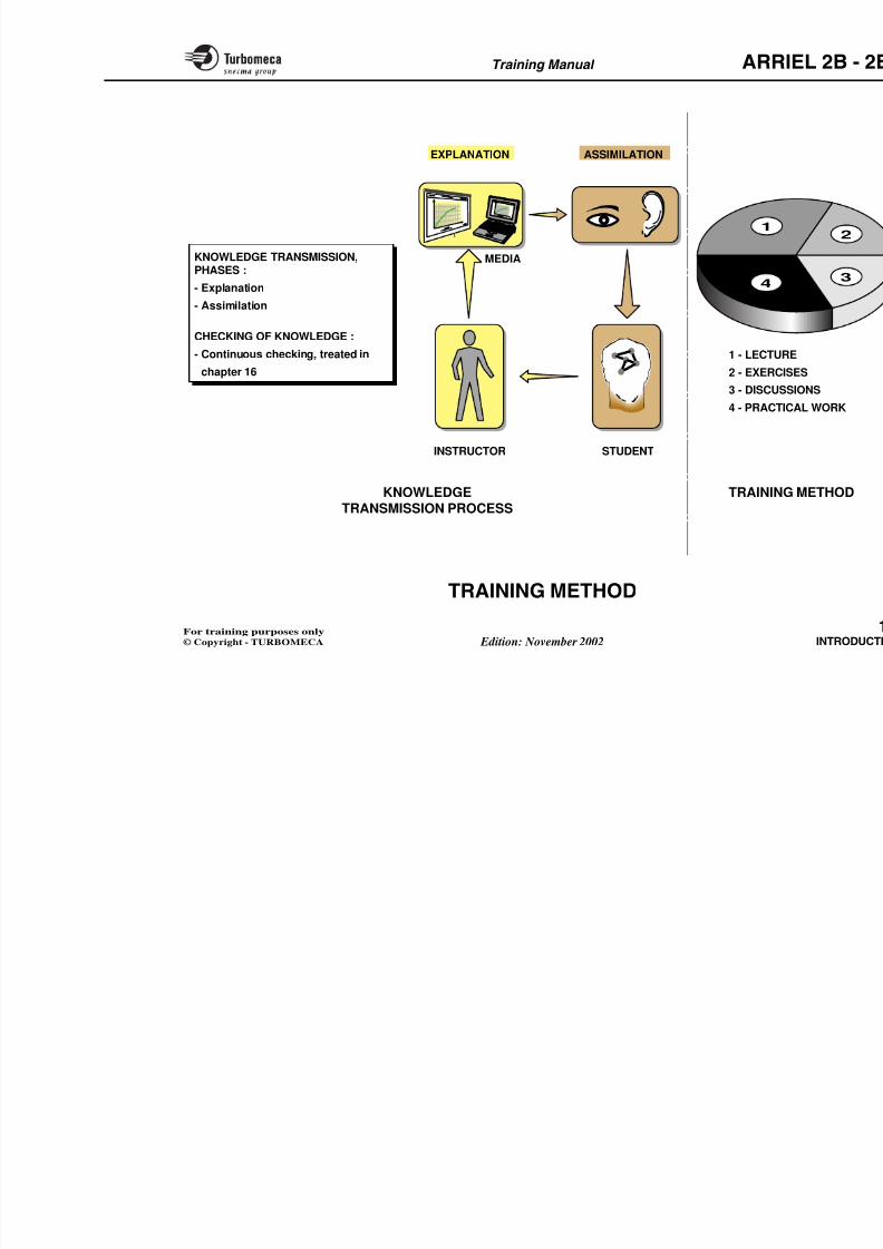
TRAINING METHOD
Knowledge transmission process
The required knowledge is transmitted in such a mannerthat the student may use it efficiently in variouscircumstances.
The training is conducted in accordance with a processwhich considers :
- A phase of explanation for understanding
- A phase of assimilation leading to the complete acqui-sition and long-term retention of the knowledge.
Continuous checking of knowledge helps to ensure theinformation is assimilated. It is more a method of work than a testing in the traditional sense (refer to chapter 16).
Training method
The training method is a carefully bof:
- Lecture
- Exercises
- Discussions
- Practical work.
8/13/2019 Arriel_2B-2B1 11-02 En
http://slidepdf.com/reader/full/arriel2b-2b1-11-02-en 16/461
Training Manual ARR
1
4
KNOWLEDGETRANSMISSION PROCESS
TRAININ
1 - LECTU2 - EXERC
3 - DISCUS
4 - PRACT
INSTRUCTOR
MEDIA
STUDENT
EXPLANATION ASSIMILATION
KNOWLEDGE TRANSMISSION,PHASES :
- Explanation
- Assimilation
CHECKING OF KNOWLEDGE :
- Continuous checking, treated inchapter 16
8/13/2019 Arriel_2B-2B1 11-02 En
http://slidepdf.com/reader/full/arriel2b-2b1-11-02-en 17/461
Training Manual ARR
TRAINING AIDS
Training manual
The training manual is the basic source of information.
It contains, in a teaching form, all required informationand explanations, following a layout derived from theATA 104 standard. Thus each subject is treated followinga plan which allows the material to be adapted to differentlevels of training.
Typical plan:
- General (function, position, main characteristics, maincomponents)
- Description (general and detailed)
- Operation (phases, synthesis).
Other technical publications are also used during a course.
Computer Aided Presentation
Computer Aided Presentation consists of a file whichpermits the display of all the training manual illustrationsby a computer for projection.
The Computer Aided Presentation replaces thetransparencies which were used before to display thesesame illustrations
Multimedia coursewareThe multimedia courseware is a Compsoftware following the training maninformation in a teaching and interac
This multimedia system uses text, psounds, animation and video. Questiofor check-up of knowledge.
It forms the essential support of trensures their uniformity.
This system with quick and easy efficient for maintaining knowledge le
However, only a course delivered binstructor or TURBOMECA qualifi
lead to the issue of an engine maintecard.
Note : The multimedia courseware Aided Presentation are ava(contact the training centre foavailability).
Demonstration mock-upsDemonstration mock-ups are also uidentification and maintenance proce

8/13/2019 Arriel_2B-2B1 11-02 En
http://slidepdf.com/reader/full/arriel2b-2b1-11-02-en 18/461
Training Manual ARR
COMPUTER AIDED P
TRAINING MANUAL
Note : Theinformation contained in
the Training Aids must be
considered for trainingpurposes only.

8/13/2019 Arriel_2B-2B1 11-02 En
http://slidepdf.com/reader/full/arriel2b-2b1-11-02-en 19/461
Training Manual ARR
TRAINING PROGRAMME
The course programme follows the manual. However, itshould be noted that the "classroom sessions" alternatewith periods devoted to demonstrations and practicalwork.
According to the contents, each session is mainly devotedto description and operation.
The engine maintenance aspect is mainly covered by the
last part of the manual, which also deals with variouselements related to maintenance (standard practices,technical publications, logistics and mainly troubleshooting).
Examples of programme:
The following pages provide exprogramme:
- Familiarization course
- 1st line maintenance (O level): prevmaintenance
- 2nd line maintenance (I level): mod
- 3rd line maintenance (H level): dee
- 4th line maintenance (D level): rep
8/13/2019 Arriel_2B-2B1 11-02 En
http://slidepdf.com/reader/full/arriel2b-2b1-11-02-en 20/461
Training Manual ARR
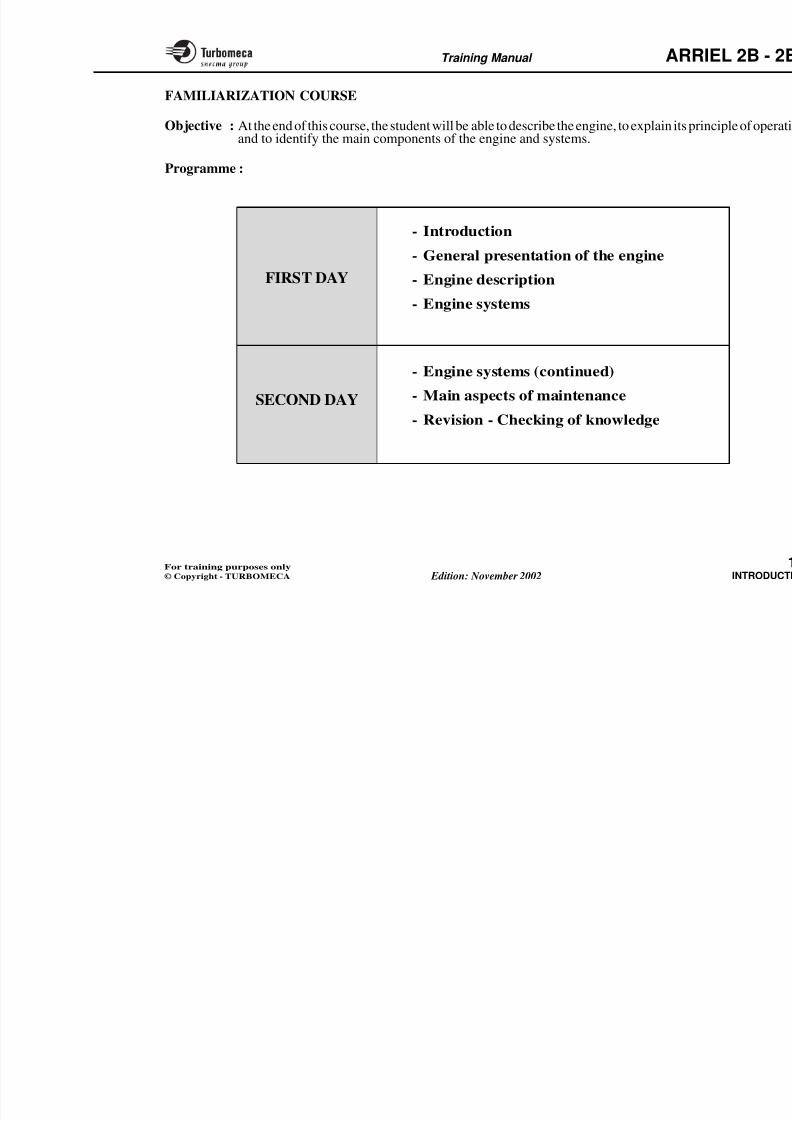
FAMILIARIZATION COURSE
Objective : At the end of this course, the student will be able to describe the engine, to explain its prand to identify the main components of the engine and systems.
Programme :
- Engine systems (continued)
- Main aspects of maintenance
- Revision - Checking of knowledge
FIRST DAY
SECOND DAY
- Introduction
- General presentation of the engine
- Engine description
- Engine systems
8/13/2019 Arriel_2B-2B1 11-02 En
http://slidepdf.com/reader/full/arriel2b-2b1-11-02-en 21/461
Training Manual ARR
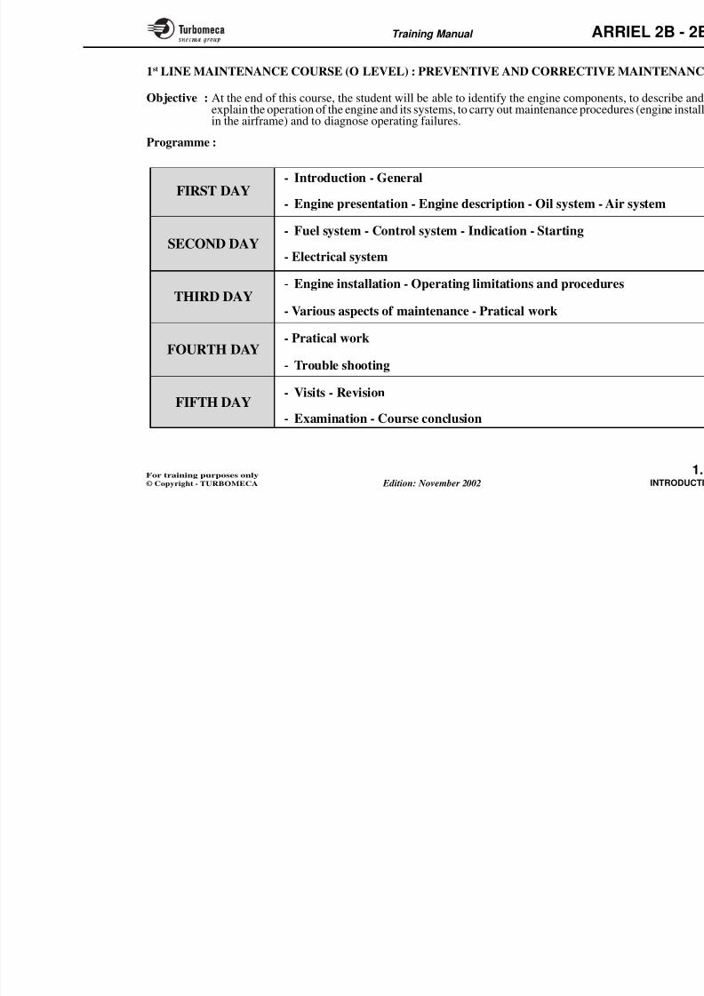
1st LINE MAINTENANCE COURSE (O LEVEL) : PREVENTIVE AND CORRECTIVE M
Objective : At the end of this course, the student will be able to identify the engine componentsexplain the operation of the engine and its systems, to carry out maintenance procedurin the airframe) and to diagnose operating failures.
Programme :
FIRST DAY
SECOND DAY
THIRD DAY
FOURTH DAY
FIFTH DAY
- Introduction - General
- Engine presentation - Engine description - Oil system - Air
- Fuel system - Control system - Indication - Starting
- Electrical system
- Engine installation - Operating limitations and procedures
- Various aspects of maintenance - Pratical work
- Pratical work
- Trouble shooting
- Visits - Revision
Examination Course conclusion
8/13/2019 Arriel_2B-2B1 11-02 En
http://slidepdf.com/reader/full/arriel2b-2b1-11-02-en 22/461
Training Manual ARR
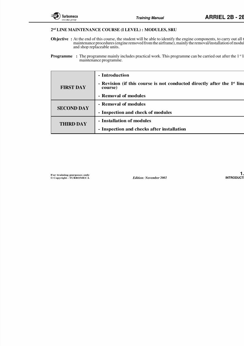
2nd LINE MAINTENANCE COURSE (I LEVEL) : MODULES, SRU
Objective : At the end of this course, the student will be able to identify the engine componentsmaintenance procedures (engine removed from the airframe), mainly the removal/instand shop replaceable units.
Programme : The programme mainly includes practical work. This programme can be carried maintenance programme.
- Introduction
- Revision (if this course is not conducted directly aftcourse)
- Removal of modules
- Removal of modules
- Inspection and check of modules
- Installation of modules
- Inspection and checks after installation
FIRST DAY
SECOND DAY
THIRD DAY
8/13/2019 Arriel_2B-2B1 11-02 En
http://slidepdf.com/reader/full/arriel2b-2b1-11-02-en 23/461
Training Manual ARR
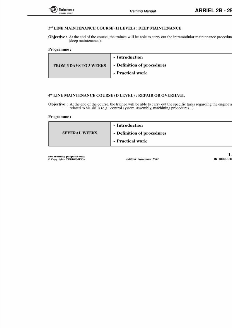
3rd LINE MAINTENANCE COURSE (H LEVEL) : DEEP MAINTENANCE
Objective : At the end of the course, the trainee will be able to carry out the intramodular maint(deep maintenance).
Programme :
- Introduction
- Definition of procedures
- Practical work
FROM 3 DAYS TO 3 WEEKS
- Introduction
- Definition of proceduresSEVERAL WEEKS
4th LINE MAINTENANCE COURSE (D LEVEL) : REPAIR OR OVERHAUL
Objective : At the end of the course, the trainee will be able to carry out the specific tasks regardrelated to his skills (e.g.: control system, assembly, machining procedures...).
Programme :
8/13/2019 Arriel_2B-2B1 11-02 En
http://slidepdf.com/reader/full/arriel2b-2b1-11-02-en 24/461
Training Manual ARR
2-POWER PLANT
- Power plant .................................................................... 2
• General .................................................................... 2
• Description.............................................................. 2
• Operation ................................................................ 2
- Principle of adaptation to the helicopter ..................... 2
- Main characteristics ..................................................... 2
- Design and development .............................................. 2
8/13/2019 Arriel_2B-2B1 11-02 En
http://slidepdf.com/reader/full/arriel2b-2b1-11-02-en 25/461
8/13/2019 Arriel_2B-2B1 11-02 En
http://slidepdf.com/reader/full/arriel2b-2b1-11-02-en 26/461
Training Manual ARR
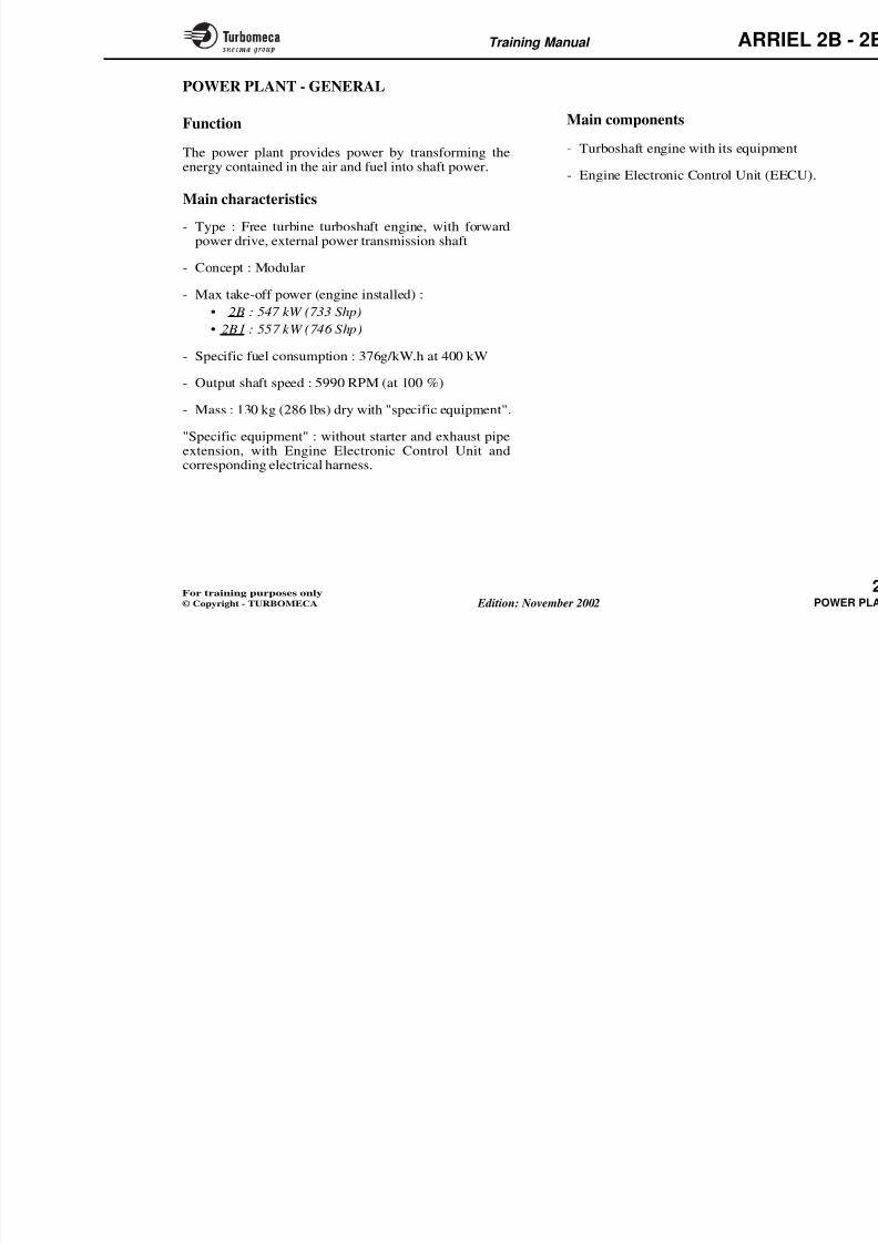
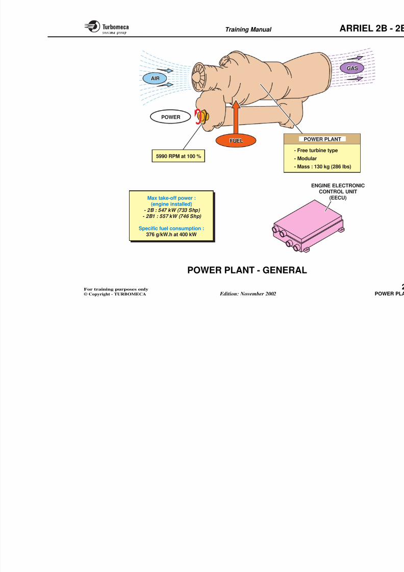
POWER PLANT
POWER
ENGINE ELECTRONCONTROL UNIT
(EECU)
- Free turbine type
- Modular
- Mass : 130 kg (286 lbs)
Max take-off power :(engine installed)
- 2B : 547 kW (733 Shp) - 2B1 : 557 kW (746 Shp)
Specific fuel consumption :376 g/kW.h at 400 kW
5990 RPM at 100 %
IRAIR
G S
FU L
GAS
FUEL
8/13/2019 Arriel_2B-2B1 11-02 En
http://slidepdf.com/reader/full/arriel2b-2b1-11-02-en 27/461
Training Manual ARR
POWER PLANT - DESCRIPTION
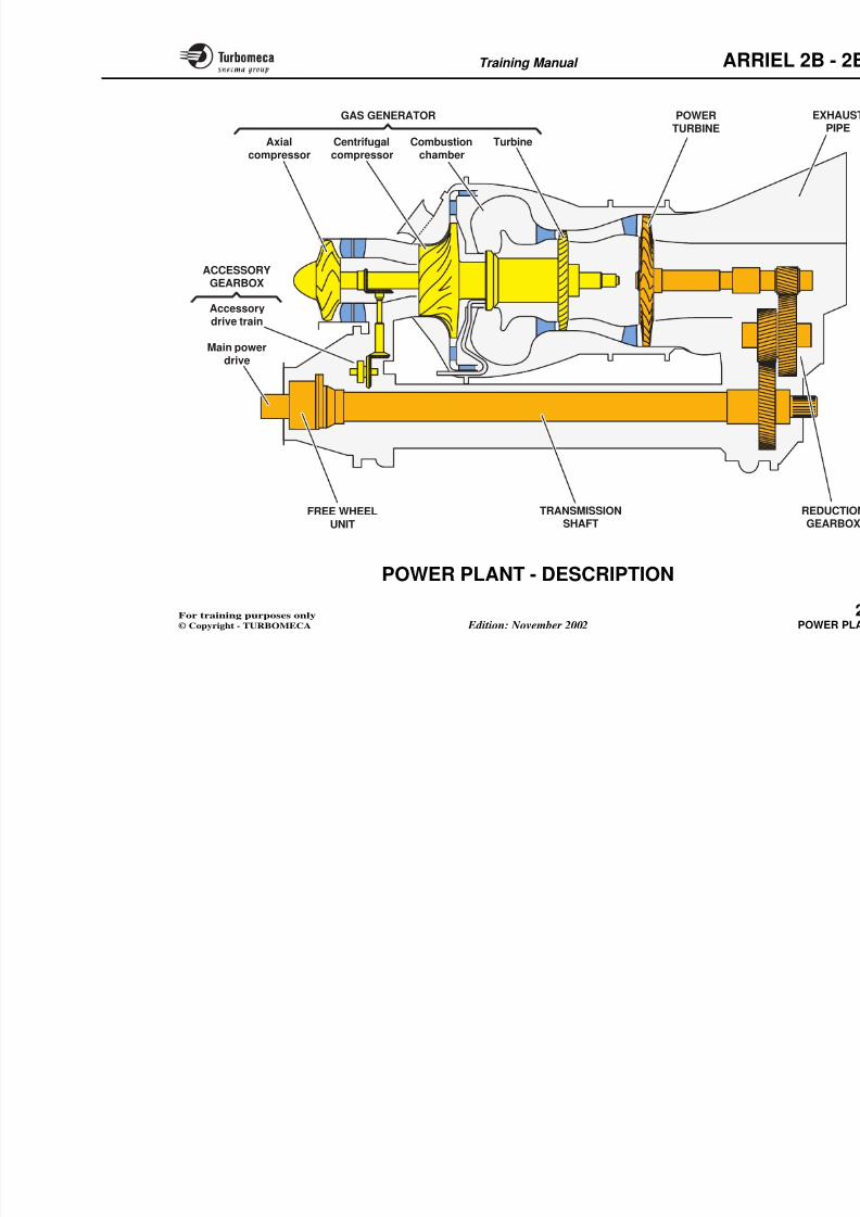
This description considers the main functional componentsof the engine.
Gas generator
- Single stage axial compressor
- Centrifugal compressor
- Annular combustion chamber with centrifugal fuelinjection
- Single-stage axial turbine.
Power turbine
- Single-stage axial turbine.
Exhaust pipe
- Elliptical, axial exhaust pipe.
Reduction gearbox
- Reduction gearbox comprising three helical gears.
Transmission shaft- External shaft located in a protection
the reduction gearbox to the acces
- An output shaft with front and reaaxially in the transmission shaft wha free wheel unit.
Accessory gearbox
- Gearbox containing the accessory drdriven by the gas generator) and th
8/13/2019 Arriel_2B-2B1 11-02 En
http://slidepdf.com/reader/full/arriel2b-2b1-11-02-en 28/461
Training Manual ARR
Accessorydrive train
Main powerdrive
ACCESSORYGEARBOX
GAS GENERATOR
Axialcompressor
Centrifugalcompressor
Combustionchamber
Turbine
POWERTURBINE
TRANSMISSIONFREE WHEEL
8/13/2019 Arriel_2B-2B1 11-02 En
http://slidepdf.com/reader/full/arriel2b-2b1-11-02-en 29/461
Training Manual ARR
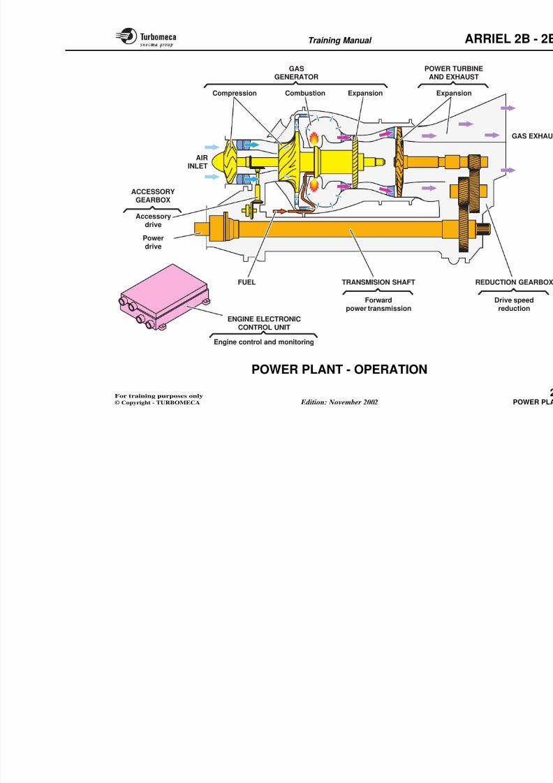
POWER PLANT - OPERATION
This part deals with the basic operation of the engine.
Gas generator
- Admission of air through the aircraft air intake
- Compression of the air in the axial and centrifugalcompressors
- Combustion of the fuel/air mixture in the annularcombustion chamber
- Gas expansion in the single stage turbine which drivesthe compressors and engine accessories.
Power turbine
- Expansion of the gas in the single stage turbine whichdrives the output shaft through the reduction gearbox.
Exhaust
- End of expansion and discharge overboard of the gas.
Reduction gearbox
- Reduces the power turbine rotation speed and transmitsthe power forwards
Transmission shaft- Transmission of the power from th
to the output shaft.
Accessory gearbox
- Power take-off to drive the helicop
- Drive of the accessories by the gasbevel gear, a vertical drive shaft an
Engine Electronic Control Unit
- Control and monitoring of the eng
8/13/2019 Arriel_2B-2B1 11-02 En
http://slidepdf.com/reader/full/arriel2b-2b1-11-02-en 30/461
Training Manual ARR
GAS
GENERATOR
Compression Combustion Expansion
POWER TURBINE
AND EXHAUST
REDTRANSMISION SHAFT
ACCESSORYGEARBOX
Expansion
AIRINLET
Accessory
drive
Forwardpower transmission
FUEL
ENGINE ELECTRONICCONTROL UNIT
Powerdrive
8/13/2019 Arriel_2B-2B1 11-02 En
http://slidepdf.com/reader/full/arriel2b-2b1-11-02-en 31/461
Training Manual ARR
POWER PLANT - OPERATION -
ADAPTATION
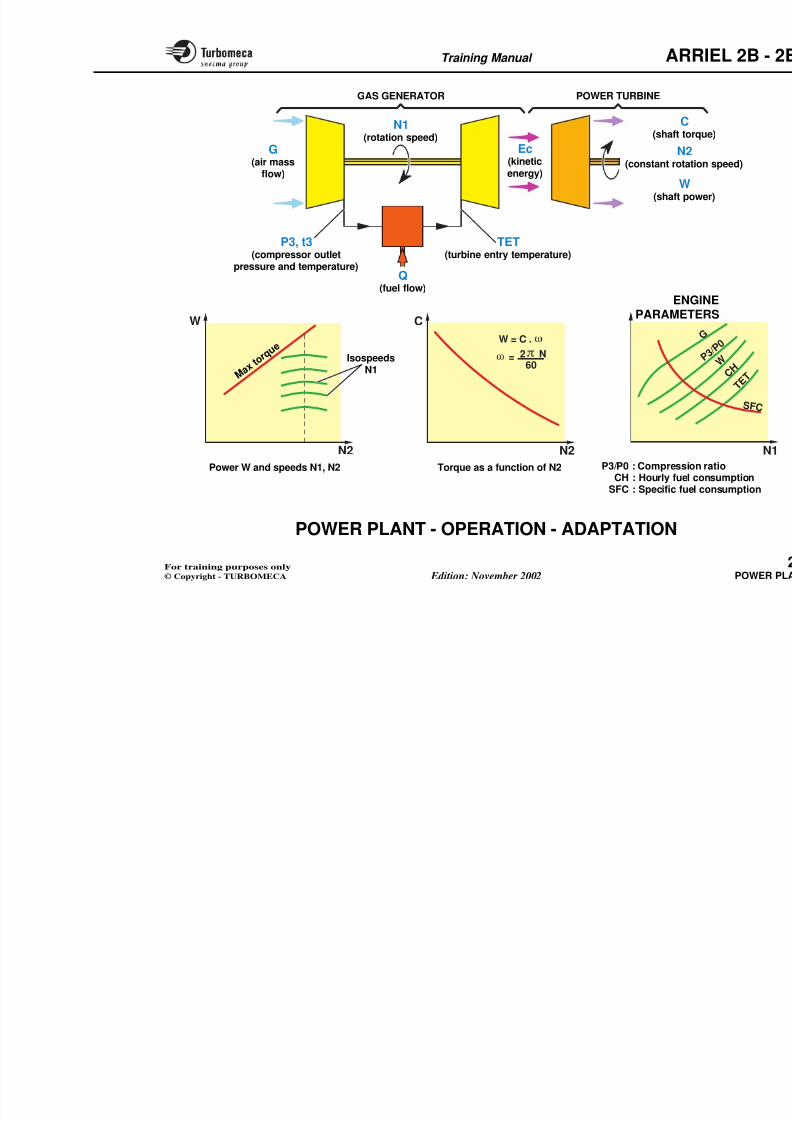
This part deals with the parameters and the adaptation of the gas generator and power turbine.
Component adaptation
For the engine operation, two functional assemblies can beconsidered :
- The gas generator which provides kinetic energy
- The power turbine which transforms the gas energy intomechanical power on a shaft.
The two assemblies have different rotation speeds.
Gas generator
The gas generator operation is defined by :
- The air mass flow G (air flow which enters the engine)
- The air pressure P3 and air temperature t3 at thecentrifugal compressor outlet
- The fuel flow Q injected into the combustion chamber
- The gas temperature TET at the turbine entry
Th i d N1 f h
Power turbine
The power turbine operation is defbetween the power received from the gtorque applied on the shaft, that is trotation speed N2.
Operation
The operation is represented by the dthe power W, the rotation speeds N1torque limit C imposed by the mech
- The torque C is a function of the N
- The power W is equal to the torqueangular velocity ω
- At constant N2 speed, the power is torque
- The engine parameters can be reprof a reference parameter ; N1 for e
8/13/2019 Arriel_2B-2B1 11-02 En
http://slidepdf.com/reader/full/arriel2b-2b1-11-02-en 32/461
Training Manual ARR
W
N2
C
N2
G
P
W = C .
= 2 N60
G(air mass
flow)
N1(rotation speed)
N2(constant rotatio
C(shaft torq
Q(fuel flow)
TET(turbine entry temperature)
P3, t3(compressor outlet
pressure and temperature)
Ec(kineticenergy)
W(shaft pow
GAS GENERATOR POWER TURBINE
ENGIPARAMETE
Power W and speeds N1, N2 P3/P0 : CompressionTorque as a function of N2
M a x t
o r q u
eIsospeeds
N1
8/13/2019 Arriel_2B-2B1 11-02 En
http://slidepdf.com/reader/full/arriel2b-2b1-11-02-en 33/461
Training Manual ARR
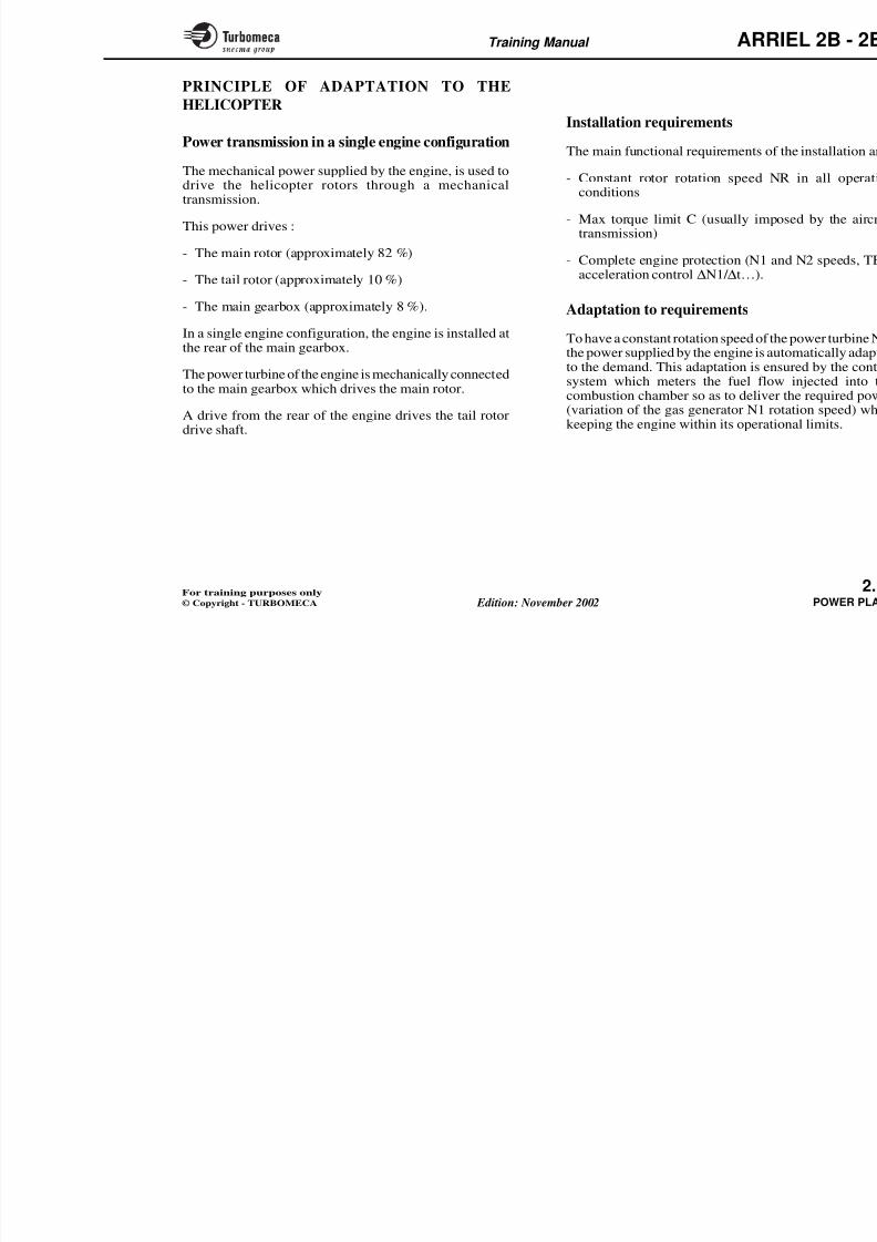
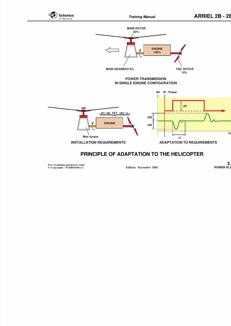
PRINCIPLE OF ADAPTATION TO THE
HELICOPTER
Power transmission in a single engine configuration
The mechanical power supplied by the engine, is used todrive the helicopter rotors through a mechanicaltransmission.
This power drives :
- The main rotor (approximately 82 %)
- The tail rotor (approximately 10 %)
- The main gearbox (approximately 8 %).
In a single engine configuration, the engine is installed atthe rear of the main gearbox.
The power turbine of the engine is mechanically connectedto the main gearbox which drives the main rotor.
A drive from the rear of the engine drives the tail rotordrive shaft.
Installation requirements
The main functional requirements of
- Constant rotor rotation speed Nconditions
- Max torque limit C (usually imptransmission)
- Complete engine protection (N1 aacceleration control ∆N1/ ∆t…).
Adaptation to requirements
To have a constant rotation speed of th
the power supplied by the engine is auto the demand. This adaptation is ensystem which meters the fuel flowcombustion chamber so as to deliver(variation of the gas generator N1 rokeeping the engine within its operati
8/13/2019 Arriel_2B-2B1 11-02 En
http://slidepdf.com/reader/full/arriel2b-2b1-11-02-en 34/461
Training Manual ARR
N2
∆N2
∆N2
∆W
POWER TRANSMISSIONIN SINGLE ENGINE CONFIGURATION
W - Power
MAIN ROTOR
82%
MAIN GEARBOX 8% TAIL ROTOR
10%
Max torque
NR
N1, N2, TET, ∆N1/∆t
ENGINE100%
ENGINE
8/13/2019 Arriel_2B-2B1 11-02 En
http://slidepdf.com/reader/full/arriel2b-2b1-11-02-en 35/461
Training Manual ARR
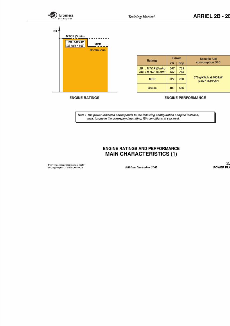
MAIN CHARACTERISTICS (1)
Engine ratings
The engine ratings correspond to given conditions of helicopter operation. The ratings are generally definedunder determined speed and temperature conditions.
The following ratings are considered:
• Max take-off power: max rating which can be used
during take-off. This rating has a limited duration(5 minutes continuous)
• Max continuous power : rating which can be usedwithout time limitation (this does not imply that it isused permanently).
Engine performance
The performance values specified correspond to minimumvalues defined under the following conditions:
- ISA conditions at sea level on test bed
- Engine equipped with a test bed air intake and a primaryexhaust pipe
- No air bleed
- No extra power taken (other than those of the engineaccessories)
- With a given calorific power of fu
- Without torque limitations.
The power is the power available onexpressed in kilowatt (kW) or shaft h
The fuel consumption (CH or WF) i
consumed in a unit of time. It is expreper hour (kg/hr).
The specific fuel consumption (SFfuel required to produce one unit of time (SFC = CH/W). It is expressed inkilowatt per hour (g/kW.hr).
Note : 1 kW = 1.34 Shp.
8/13/2019 Arriel_2B-2B1 11-02 En
http://slidepdf.com/reader/full/arriel2b-2b1-11-02-en 36/461
Training Manual ARR
N1
Note : The power indicated corresponds to the following configuration : engine installed,max. torque in the corresponding rating, ISA conditions at sea level.
Ratings
547 557
522
400
733 746
700
536Cruise
MCP
kW Shp
Power Sp
consu
376 g/k(0.82
2B : MTOP (5 min) 2B1 : MTOP (5 min)
MTOP (5 min)
Continuous
MCP2B: 547 kW
2B1:557 kW
ENGINE RATINGS ENGINE PERFORMANC
8/13/2019 Arriel_2B-2B1 11-02 En
http://slidepdf.com/reader/full/arriel2b-2b1-11-02-en 37/461
Training Manual ARR
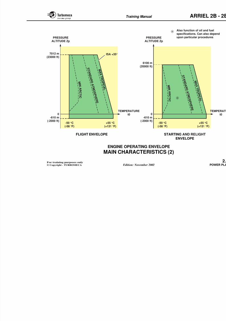
MAIN CHARACTERISTICS (2)
Engine operating envelope
The engine is designed to operate within a given climaticenvelope.
The envelope is defined by:
- The atmospheric temperature t0
- The pressure altitude Zp
- And lines of standard atmosphere.
Flight envelope
The flight envelope is illustrated by the t0/Zp diagram andthe lines of standard atmosphere, with the max tropical
zone and the min arctic zone.
Starting and relight envelope
The starting and relight envelope is defined in the sameway, but it is also affected by the specifications of oil andfuel used, and sometimes by particular procedures.
Note : The engine operates within vrotation speeds, temperature
Refer to corresponding ch publications.
8/13/2019 Arriel_2B-2B1 11-02 En
http://slidepdf.com/reader/full/arriel2b-2b1-11-02-en 38/461
Training Manual ARR
7012 m(23000 ft)
6100 m(20000 ft)
+55 °C(+131 °F)
-610 m(-2000 ft)
-50 °C(-58 °F)
+(+
-610 m(-2000 ft)
-50 °C(-58 °F)
ISA +35°
0 0
M I N A R
C T I C
PRESSURE
ALTITUDE Zp
TEMPERATURE
t0
FLIGHT ENVELOPE
PRESSURE
ALTITUDE Zp
STARTING AND RELIG
Also function of ospecifications. Caupon particular p
M A X T R O P I C A L
S T A N D A R D A T M O S P
H E R E
M I N
A R C T I C
M A X T R
O P I C A L
S T A N D A R D
A T M O S P H E R E
8/13/2019 Arriel_2B-2B1 11-02 En
http://slidepdf.com/reader/full/arriel2b-2b1-11-02-en 39/461
Training Manual ARR
DESIGN AND DEVELOPMENT
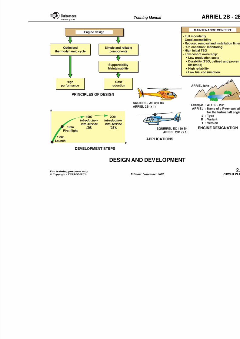
Principles of design
The engine is designed to meet the aircraft propulsionrequirements and particularly for the new generation of helicopters.
The engine design is based on:
- An optimised thermodynamic cycle which gives high
performance- Simple and reliable components giving a good
supportability, and a good maintainability to reduce thecosts.
Development steps
- Launch ARRIEL 2: 1992
- ARRIEL 2B certification: Nov. 97 (JAA)- Introduction into service:
• December 1997 - ARRIEL 2B
• March 2001 - ARRIEL 2B1.
Applications
The ARRIEL 2B and 2B1 are actually provided to power
the single engine helicopters:
- Squirrel AS 350 B3 - ARRIEL 2B
S i l EC 130 B4 ARRIEL 2B1
Maintenance concept
The ARRIEL 2 is designed to providrate with reduced maintenance costs
The main aspects of the maintenanfollowing:
- Full modularity
- Good accessibility
- Reduced removal and installation
- "On condition" monitoring
- High initial TBO
- Low cost of ownership:
• Low production costs
• Durability (TBO, defined and p
• High reliability
• Low fuel consumption.
Engine designation
ARRIEL - According to TURBOMEof a Pyrenean lake for the turboshaft
- 2 : Type
- B : Variant
8/13/2019 Arriel_2B-2B1 11-02 En
http://slidepdf.com/reader/full/arriel2b-2b1-11-02-en 40/461
Training Manual ARR
ENGINE
Optimisedthermodynamic cycle
Simple and reliablecomponents
SupportabilityMaintainability
Costreduction
Highperformance
1997Introduction
into service (2B)
2001Introduction
into service (2B1) 1994
First flight
1992Launch
PRINCIPLES OF DESIGN
ARRIEL lake
Engine design
Example : ARRARRIEL : Nam
for t2 : TypB : Var1 : Vers
MAINTENANC
- Full modularity- Good accessibility- Reduced removal a- "On condition" mon- High initial TBO- Low cost of owners• Low production c• Durability (TBO, d
life limits)• High reliability• Low fuel consum
APPLICATIONS
SQUIRREL AS 350 B3ARRIEL 2B (x 1)
SQUIRREL EC 130 B4ARRIEL 2B1 (x 1)
EC130
8/13/2019 Arriel_2B-2B1 11-02 En
http://slidepdf.com/reader/full/arriel2b-2b1-11-02-en 41/461
8/13/2019 Arriel_2B-2B1 11-02 En
http://slidepdf.com/reader/full/arriel2b-2b1-11-02-en 42/461
Training Manual ARR
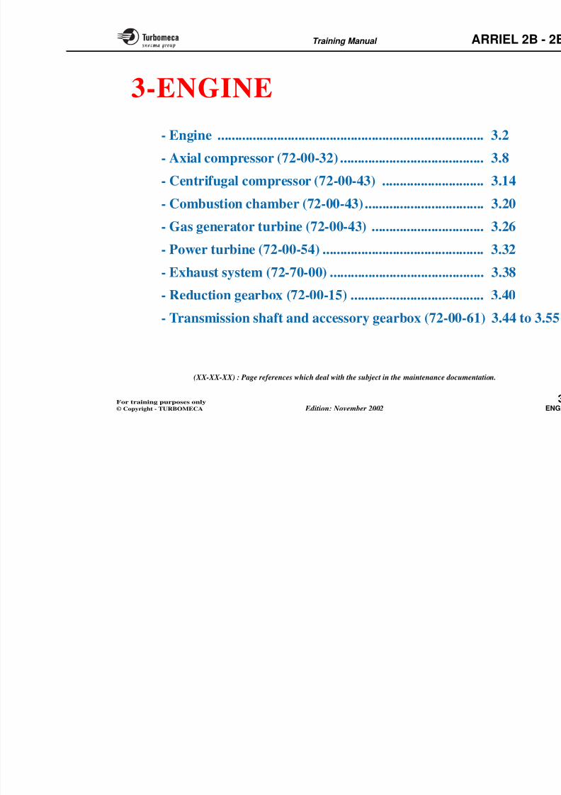
3-ENGINE
- Engine ............................................................................ 3
- Axial compressor (72-00-32) ......................................... 3
- Centrifugal compressor (72-00-43) ............................. 3
- Combustion chamber (72-00-43) .................................. 3
- Gas generator turbine (72-00-43) ................................ 3- Power turbine (72-00-54) .............................................. 3
- Exhaust system (72-70-00) ............................................ 3
- Reduction gearbox (72-00-15) ...................................... 3
- Transmission shaft and accessory gearbox (72-00-61) 3
8/13/2019 Arriel_2B-2B1 11-02 En
http://slidepdf.com/reader/full/arriel2b-2b1-11-02-en 43/461
Training Manual ARR
ENGINE - GENERAL
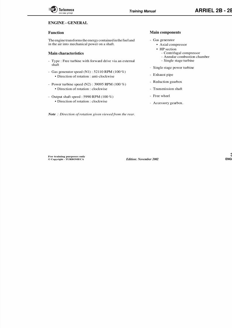
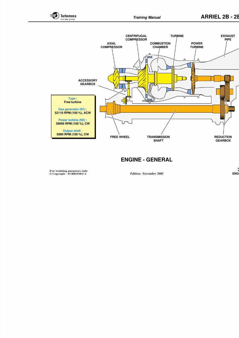
Function
The engine transforms the energy contained in the fuel andin the air into mechanical power on a shaft.
Main characteristics
- Type : Free turbine with forward drive via an external
shaft
- Gas generator speed (N1) : 52110 RPM (100 %)
• Direction of rotation : anti-clockwise
- Power turbine speed (N2) : 39095 RPM (100 %)
• Direction of rotation : clockwise
- Output shaft speed : 5990 RPM (100 %)
• Direction of rotation : clockwise
Note : Direction of rotation given viewed from the rear.
Main components
- Gas generator
• Axial compressor
• HP section- Centrifugal compressor- Annular combustion chamb- Single stage turbine
- Single stage power turbine
- Exhaust pipe
- Reduction gearbox
- Transmission shaft
- Free wheel
- Accessory gearbox.

8/13/2019 Arriel_2B-2B1 11-02 En
http://slidepdf.com/reader/full/arriel2b-2b1-11-02-en 44/461
Training Manual ARR
TRANSMISSIONSHAFT
ACCESSORYGEARBOX
Type :Free turbine
Gas generator (N1) :52110 RPM (100 %), ACW
Power turbine (N2) :39095 RPM (100 %), CW
Output shaft :5990 RPM (100 %), CW
TURBINECENTRIFUGALCOMPRESSOR
POWERTURBINE
COMBUSTIONCHAMBER
AXIALCOMPRESSOR
FREE WHEEL
8/13/2019 Arriel_2B-2B1 11-02 En
http://slidepdf.com/reader/full/arriel2b-2b1-11-02-en 45/461
Training Manual ARR
ENGINE - DESCRIPTION
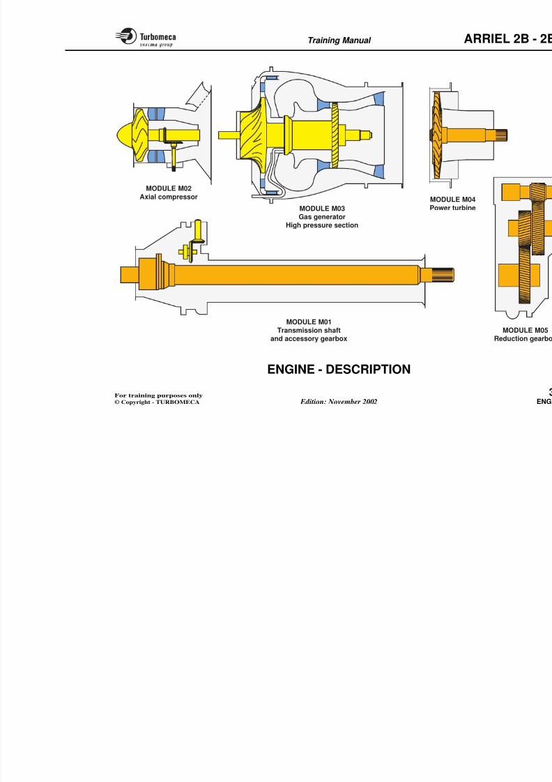
Modular layout
The engine comprises 5 modules:
- Module M01 : Transmission shaft and accessory gearbox
- Module M02 : Axial compressor
- Module M03 : Gas generator HP section
- Module M04 : Power turbine
- Module M05 : Reduction gearbox.
Note 1 : A module is a sub-assemreplaced on-site (2nd line mcomplex tooling or adapta
Each module has an idenengine identification platehand side of the M01 prot
Note 2 : Some accessories are pmodule.
In this manual, those compin the chapters corresposystems.
Note 3 : The exhaust pipe is not a m
8/13/2019 Arriel_2B-2B1 11-02 En
http://slidepdf.com/reader/full/arriel2b-2b1-11-02-en 46/461
Training Manual ARR
MODULE M02
Axial compressor
MODULE M03Gas generator
High pressure section
MODULE M04
Power turbine
MODULE M01
8/13/2019 Arriel_2B-2B1 11-02 En
http://slidepdf.com/reader/full/arriel2b-2b1-11-02-en 47/461
Training Manual ARR
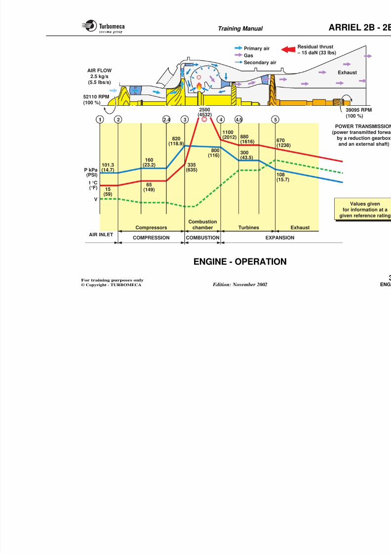
ENGINE - OPERATION
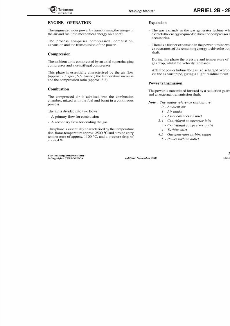
The engine provides power by transforming the energy inthe air and fuel into mechanical energy on a shaft.
The process comprises compression, combustion,expansion and the transmission of the power.
Compression
The ambient air is compressed by an axial superchargingcompressor and a centrifugal compressor.
This phase is essentially characterised by the air flow(approx. 2.5 kg/s ; 5.5 lbs/sec.) the temperature increaseand the compression ratio (approx. 8.2).
Combustion
The compressed air is admitted into the combustionchamber, mixed with the fuel and burnt in a continuousprocess.
The air is divided into two flows:
- A primary flow for combustion
- A secondary flow for cooling the gas.
This phase is essentially characterised by the temperaturerise, flame temperature approx. 2500 °C and turbine entrytemperature of approx 1100 °C and a pressure drop of
Expansion
- The gas expands in the gas geneextracts the energy required to driveaccessories.
- There is a further expansion in the extracts most of the remaining enershaft.
During this phase the pressure and
gas drop, whilst the velocity incre
After the power turbine the gas is dvia the exhaust pipe, giving a sligh
Power transmission
The power is transmitted forward by
and an external transmission shaft.
Note : The engine reference station
0 - Ambient air
1 - Air intake
2 - Axial compressor inlet
2.4 - Centrifugal compressor
3 - Centrifugal compressor4 - Turbine inlet
4.5 - Gas generator turbine o
8/13/2019 Arriel_2B-2B1 11-02 En
http://slidepdf.com/reader/full/arriel2b-2b1-11-02-en 48/461
Training Manual ARR
1 4.5
160(23.2)
65(149)
820(118.9)
335(635)
1100(2012) 880
(1616)
300(43.5)
670(1238)
800(116)
54
101.3(14.7)
15(59)
P kPa(PSI)
t °C(°F)
V
52110 RPM(100 %)
108(15.7)
11 2 2.4 3
2500(4532)
CompressorsCombustion
chamber Turbines Exhaust
POW(powe
by a
and
fo
giv
Primary air
GasSecondary air
AIR FLOW2.5 kg/s
(5.5 lbs/s)
Residual thrust
≈ 15 daN (33 lbs)
Exh
8/13/2019 Arriel_2B-2B1 11-02 En
http://slidepdf.com/reader/full/arriel2b-2b1-11-02-en 49/461
Training Manual ARR
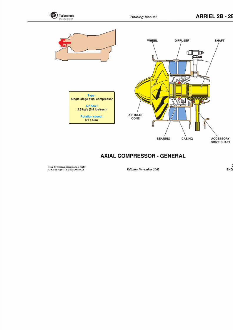
AXIAL COMPRESSOR - GENERAL
Function
The axial compressor ensures a first stage of compressionto supercharge the centrifugal compressor.
Position
- At the front of the engine (the axial compressor assembly
forms the module M02).
Main characteristics
- Type : single stage axial compressor
- Air flow : 2.5 kg/sec (5.5 lbs/sec.)
- Rotation speed : N1 ; ACW.
Main components
- Rotating components
• Air inlet cone
• Axial wheel, shaft, bearing ashaft
- Stationary components
• Diffuser
• Casing.
8/13/2019 Arriel_2B-2B1 11-02 En
http://slidepdf.com/reader/full/arriel2b-2b1-11-02-en 50/461
Training Manual ARR
WHEEL DIFFUSER
BEARING CASING
AIR INLETCONE
Type :single stage axial compressor
Air flow :2.5 kg/s (5.5 lbs/sec.)
Rotation speed :N1 ; ACW
8/13/2019 Arriel_2B-2B1 11-02 En
http://slidepdf.com/reader/full/arriel2b-2b1-11-02-en 51/461
Training Manual ARR
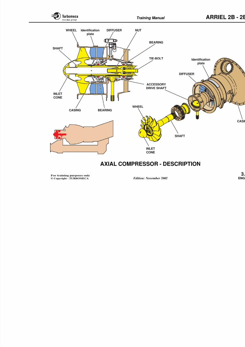
AXIAL COMPRESSOR - DESCRIPTION
The axial compressor module (module M02) includesrotating and stationary components.
Rotating components
The rotating assembly comprises the inlet cone, the axialwheel and the accessory drive gear.
The inlet cone, made of light alloy, is screwed into thefront of the shaft.
The compressor wheel is fitted to the shaft. It is a discmade of titanium alloy with blades cut from the solid.
The shaft connects the centrifugal compressor to the axialcompressor. The shaft is secured by a nut onto the tie-bolt.
This assembly is supported by two bearings: a ball bearingat the rear of the axial compressor and a ball bearing in aflexible cage at the front of the centrifugal compressor.
The accessory drive consists of a bevel gear on the shaftwhich drives a vertical drive shaft.
Stationary components
The stationary assembly includes tcasing.
The diffuser (diffuser-straightenercasing has two rows of steel stator divergent passage for the air.
The casing, made of steel, housescomponents. It has a front flange forair inlet duct and a rear flange for thmodule M03. The inner hub of the location for the bearings.
The casing has a boss for the mountinbleed valve.
The module identification plate is the casing.
8/13/2019 Arriel_2B-2B1 11-02 En
http://slidepdf.com/reader/full/arriel2b-2b1-11-02-en 52/461
Training Manual ARR
SHAFT
INLETCONE
SHAFT
CASING
ACCESSORYDRIVE SHAFT
WHEEL
WHEEL
BEARING
DIFFUSER
Identificationplate
BEARING
Identification
plate
DIFFUSER NUT
TIE-BOLT
ARR
8/13/2019 Arriel_2B-2B1 11-02 En
http://slidepdf.com/reader/full/arriel2b-2b1-11-02-en 53/461
Training Manual ARR
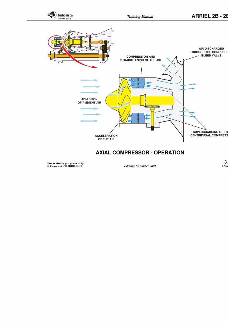
AXIAL COMPRESSOR - OPERATION
The axial compressor ensures a first stage of compressionin order to supercharge the centrifugal compressor.
Compressor air flow
The ambient air, admitted through the air intake duct andguided by the inlet cone, flows between the blades of theaxial compressor. The air is discharged rearwards with an
increased axial velocity.The air then flows through the vanes of the diffuser. Dueto the divergent passage, the air velocity is transformedinto pressure.
The flow is straightened by the stator vanes before beingadmitted, through an annular duct, to the centrifugalcompressor.
Note : In order to avoid compres
discharges overboard a certcertain operating conditioSYSTEM" chapter for furtcompressor bleed valve).
8/13/2019 Arriel_2B-2B1 11-02 En
http://slidepdf.com/reader/full/arriel2b-2b1-11-02-en 54/461
Training Manual ARR
ADMISSION
OF AMBIENT AIR
COMPRESSION AND
STRAIGHTENING OF THE AIR
AITHROUG
B
SUPERCENTRIFACCELERATION
ARR
8/13/2019 Arriel_2B-2B1 11-02 En
http://slidepdf.com/reader/full/arriel2b-2b1-11-02-en 55/461
Training Manual ARR
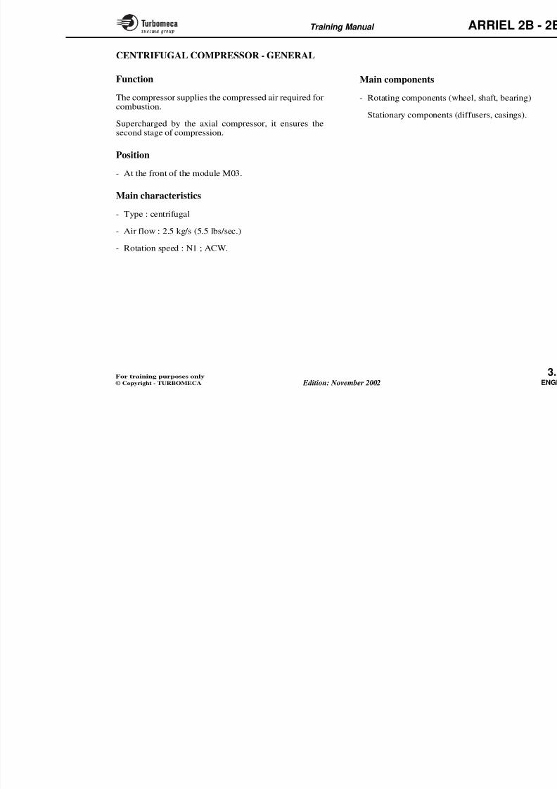
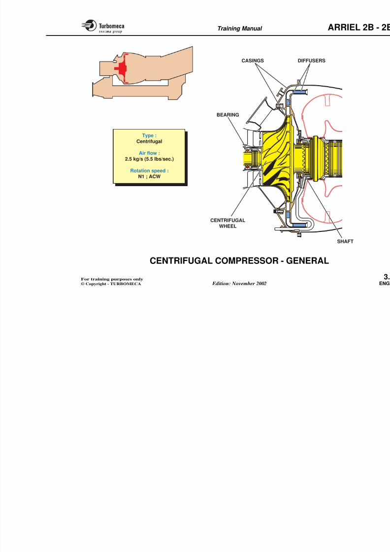
CENTRIFUGAL COMPRESSOR - GENERAL
Function
The compressor supplies the compressed air required forcombustion.
Supercharged by the axial compressor, it ensures thesecond stage of compression.
Position
- At the front of the module M03.
Main characteristics
- Type : centrifugal
- Air flow : 2.5 kg/s (5.5 lbs/sec.)
- Rotation speed : N1 ; ACW.
Main components
- Rotating components (wheel, shaf
- Stationary components (diffusers,
8/13/2019 Arriel_2B-2B1 11-02 En
http://slidepdf.com/reader/full/arriel2b-2b1-11-02-en 56/461
Training Manual ARR
DIFFUSERS
CENTRIFUGALWHEEL
CASINGS
BEARING
Type :
Centrifugal
Air flow :
2.5 kg/s (5.5 lbs/sec.)
Rotation speed :N1 ; ACW
ARR
8/13/2019 Arriel_2B-2B1 11-02 En
http://slidepdf.com/reader/full/arriel2b-2b1-11-02-en 57/461
Training Manual ARR
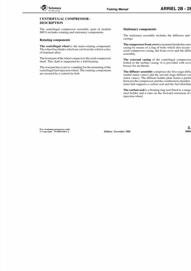
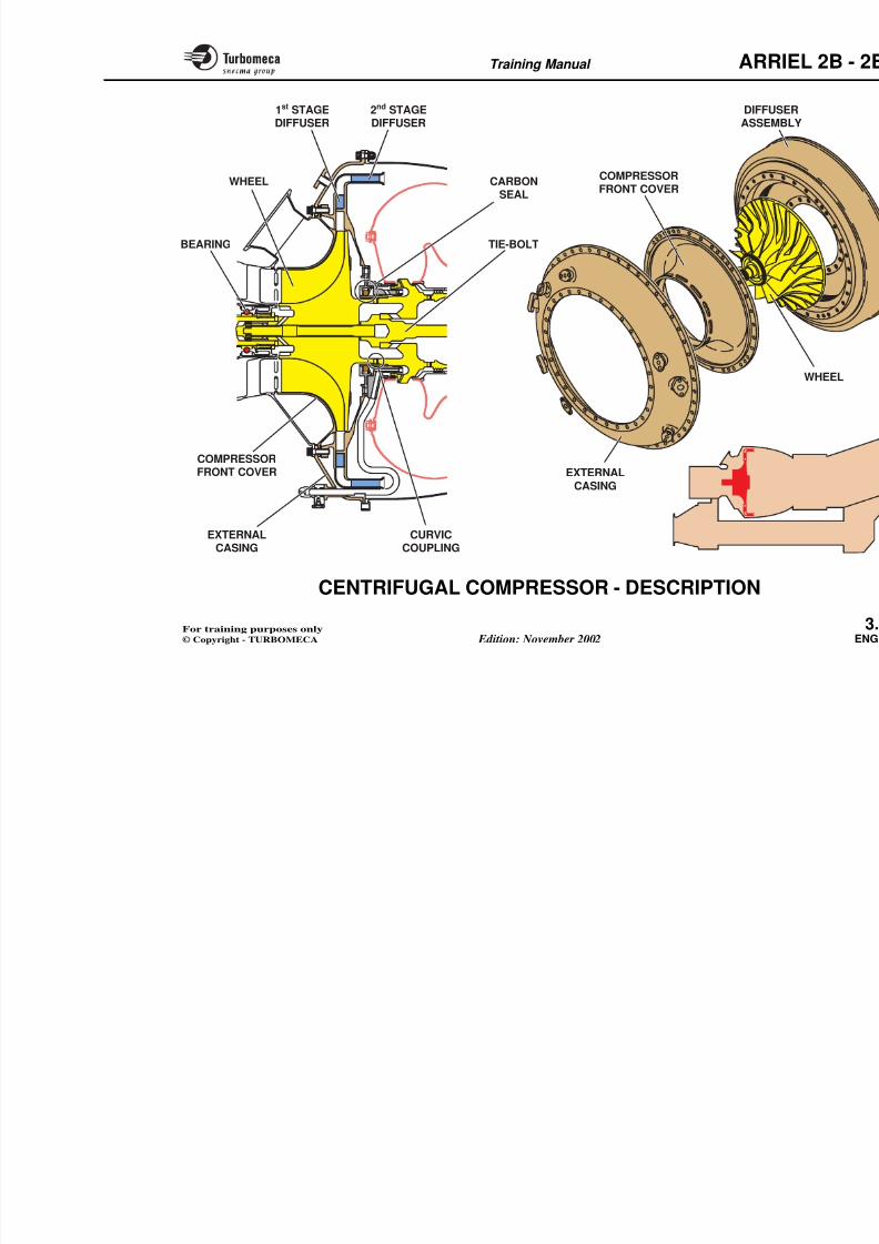
CENTRIFUGAL COMPRESSOR -
DESCRIPTION
The centrifugal compressor assembly (part of moduleM03) includes rotating and stationary components.
Rotating components
The centrifugal wheel is the main rotating component.The wheel has blades which are cut from the solid in a disc
of titanium alloy.
The front part of the wheel connects to the axial compressorshaft. This shaft is supported by a ball bearing.
The rear part has a curvic-coupling for the mounting of thecentrifugal fuel injection wheel. The rotating componentsare secured by a central tie-bolt.
Stationary components
The stationary assembly includes thcasings.
The compressor front cover is mountcasing by means of a ring of bolts waxial compressor casing, the front co
assembly.
The external casing of the centrifbolted to the turbine casing. It is prbosses for air bleeds.
The diffuser assembly comprises th(radial stator vanes) and the second
stator vanes). The diffuser holder plbetween the compressor and the cominner hub supports a carbon seal and
The carbon seal is a floating ring seasteel holder and it runs on the forwinjection wheel.
8/13/2019 Arriel_2B-2B1 11-02 En
http://slidepdf.com/reader/full/arriel2b-2b1-11-02-en 58/461
Training Manual ARR
WHEEL
BEARING
1st STAGE
DIFFUSER
2nd STAGE
DIFFUSER
COMPRESSORFRONT COVER
CARBONSEAL
TIE-BOLT
DIFFUS
ASSEM
COMPRESSORFRONT COVER
EXTERNALCASING
ARR
8/13/2019 Arriel_2B-2B1 11-02 En
http://slidepdf.com/reader/full/arriel2b-2b1-11-02-en 59/461
Training Manual ARR
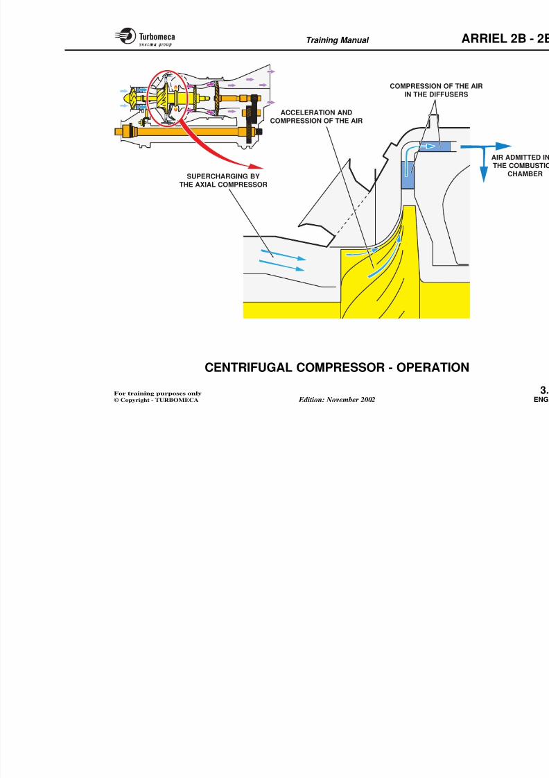
CENTRIFUGAL COMPRESSOR -
OPERATION
The centrifugal compressor ensures the main stage of compression.
Compressor air flow
The air supplied by the axial compressor flows betweenthe blades of the centrifugal compressor. The air pressure
increases due to the divergent passage between the bladesand the air velocity increases due to the centrifugal flow.
The air leaves the tips of the blades at very high velocityand then flows through the first stage diffuser vanes wherethe velocity is transformed into pressure.
The air then passes through an elbow and the flow becomesaxial. In the second stage diffuser, the velocity is again
transformed into pressure. The air is then admitted into thecombustion chamber.
8/13/2019 Arriel_2B-2B1 11-02 En
http://slidepdf.com/reader/full/arriel2b-2b1-11-02-en 60/461
Training Manual ARR
ACCELERATION ANDCOMPRESSION OF THE AIR
SUPERCHARGING BYTHE AXIAL COMPRESSOR
COMPRESSION OF THE AIR
IN THE DIFFUSERS
T i i M l ARR
8/13/2019 Arriel_2B-2B1 11-02 En
http://slidepdf.com/reader/full/arriel2b-2b1-11-02-en 61/461
Training Manual ARR
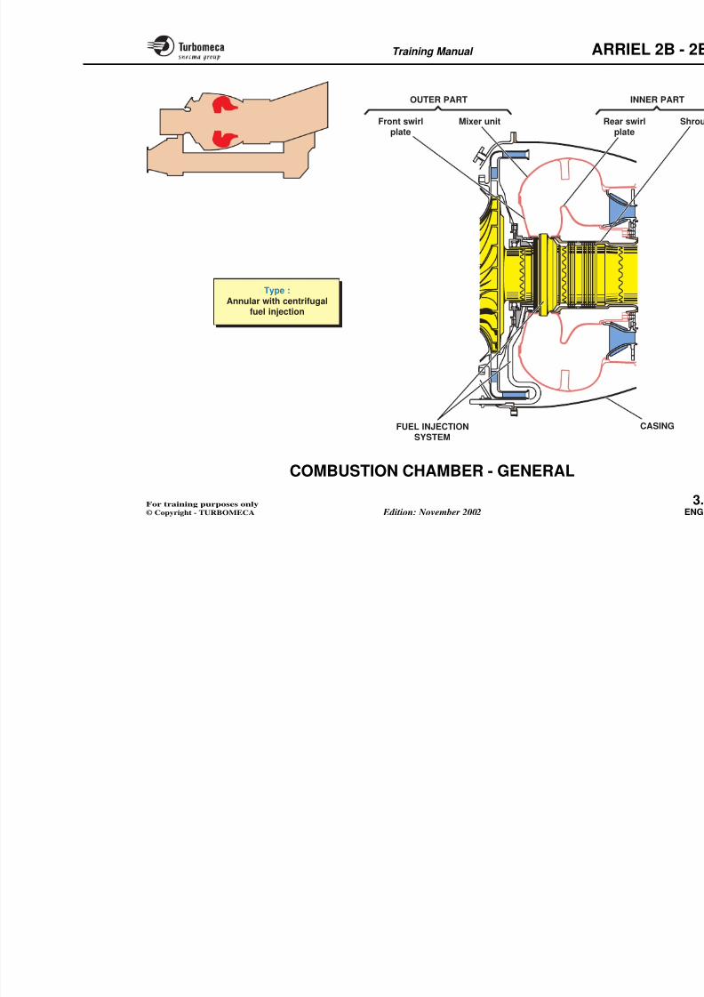
COMBUSTION CHAMBER - GENERAL
Function
The combustion chamber forms an enclosure in which theair-fuel mixture is burnt.
Position
- Central section of the gas generator.
Main characteristics
- Type : annular with centrifugal fuel injection.
Main components
- Outer part (front swirl plate and m
- Inner part (rear swirl plate and shr
- Fuel injection system
- Casing.
8/13/2019 Arriel_2B-2B1 11-02 En
http://slidepdf.com/reader/full/arriel2b-2b1-11-02-en 62/461
Training Manual ARR
OUTER PART
Front swirlplate
Mixer unit
Type :Annular with centrifugal
fuel injection
Rearpla
T i i M l ARR
8/13/2019 Arriel_2B-2B1 11-02 En
http://slidepdf.com/reader/full/arriel2b-2b1-11-02-en 63/461
Training Manual ARR
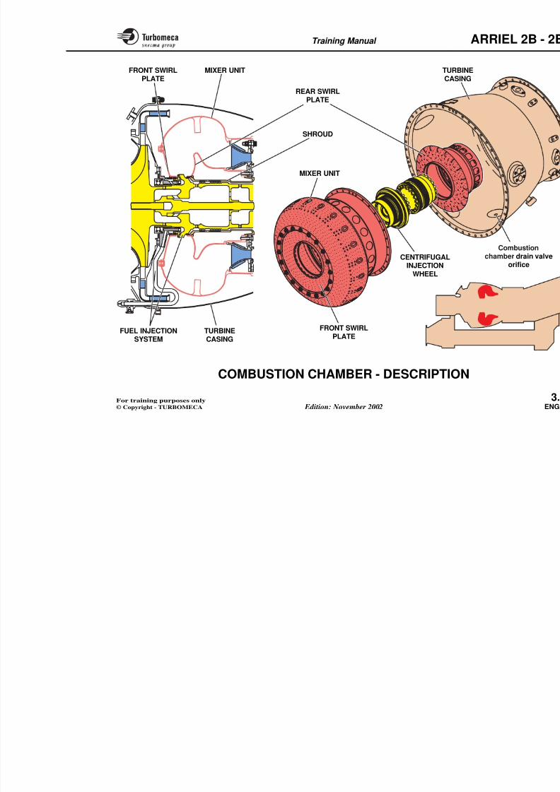
COMBUSTION CHAMBER - DESCRIPTION
The combustion chamber assembly (part of module M03)
includes the outer part, the inner part, the turbine casingand the fuel injection system.
Outer part
The outer part includes the front swirl plate and the mixerunit. The front swirl plate is provided with calibratedorifices for the passage of primary air ; it is secured to themixer unit with special rivets.
The mixer unit is provided with calibrated orifices for thepassage of dilution air ; it is bolted to the rear flange of theturbine casing.
Inner part
The inner part includes the rear swirl plate and the shroud.
The rear swirl plate is provided with calibrated orifices forthe passage of primary air.
The shroud, integral with the rear swirl plate surrounds theshaft ; it is bolted to the turbine nozzle guide vane.
Note : The two parts are made of special alloy. Thecalibrated orifices are drilled using the electron
Turbine casing
The turbine casing houses the combthe turbine. It has various bosses and,for the combustion chamber drain vathe casing.
Fuel injection system
The main fuel injection system inclunion, the radial fuel tube, the fuelcentrifugal injection wheel.
The injection wheel is mounted bcouplings between the compressor a(refer to "FUEL SYSTEM" chapter fthe fuel injection system).
8/13/2019 Arriel_2B-2B1 11-02 En
http://slidepdf.com/reader/full/arriel2b-2b1-11-02-en 64/461
Training Manual ARR
TURBINE
CASING
FRONT SWIRL
CENTRIFUGALINJECTION
WHEEL
cha
MIXER UNIT
FRONT SWIRL
PLATEREAR SWIRL
PLATE
MIXER UNIT
SHROUD
FUEL INJECTION TURBINE
Training Manual ARR
8/13/2019 Arriel_2B-2B1 11-02 En
http://slidepdf.com/reader/full/arriel2b-2b1-11-02-en 65/461
Training Manual ARR
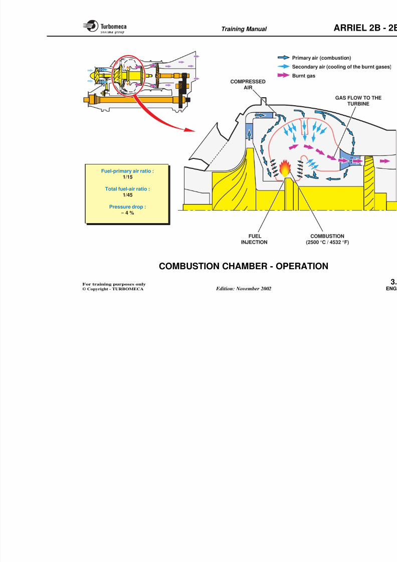
COMBUSTION CHAMBER - OPERATION
The combustion chamber forms an enclosure in which the
fuel - air mixture is burnt.
Combustion chamber flow
In the combustion chamber, the compressed air is dividedinto two flows : a primary air flow mixed with the fuel forcombustion and a secondary air flow (or dilution air flow)for cooling of the burnt gases.
Primary air
One part flows through the orifices of the front swirl plate.
A second part flows through the hollow vanes of theturbine nozzle guide vane (cooling of the vanes) andthrough the orifices of the rear swirl plate.
The primary air is mixed with the fuel sprayed by theinjection wheel. The combustion occurs between the twoswirl plates. The flame temperature reaches approximately2500 °C (4532 °F).
Secondary air
The secondary air (or dilution air)orifices of the mixer unit. It is calibrstability, cooling of the burnt gasestemperature on the turbine.
Gas
The gas produced by the combustionturbine nozzle guide vane.
Operating parameters
The fuel-air ratio for combustioapproximately 1/15 ; the total ratio is
The pressure drop in the combapproximately 4 %.
8/13/2019 Arriel_2B-2B1 11-02 En
http://slidepdf.com/reader/full/arriel2b-2b1-11-02-en 66/461
Training Manual ARR
COMPRESSEDAIR
FUEL COMBUSTION
GAS FLTU
Primary air (combustion)
Secondary air (cooling of
Burnt gas
Fuel-primary air ratio :1/15
Total fuel-air ratio :1/45
Pressure drop :≈ 4 %
Training Manual ARR
8/13/2019 Arriel_2B-2B1 11-02 En
http://slidepdf.com/reader/full/arriel2b-2b1-11-02-en 67/461
Training Manual ARR
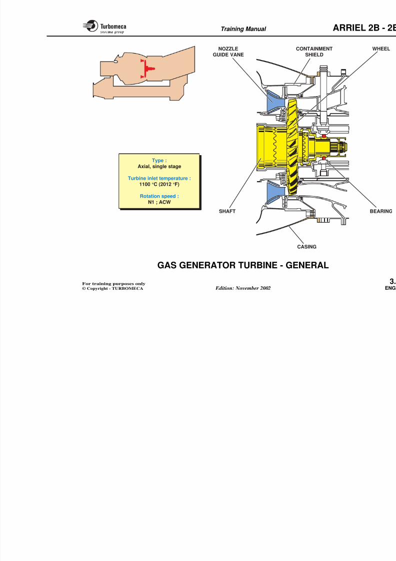
GAS GENERATOR TURBINE - GENERAL
Function
The turbine extracts sufficient energy from the gas flow todrive the compressors and the accessories.
Position
- At the rear of the gas generator.
Main characteristics
- Type : axial, single stage
- Turbine inlet temperature : 1100 °C (2012 °F)
- Rotation speed : N1 ; ACW.
Main components
- Rotating components (wheel, shaf
- Stationary components (nozzle guidshield, casing).
8/13/2019 Arriel_2B-2B1 11-02 En
http://slidepdf.com/reader/full/arriel2b-2b1-11-02-en 68/461
Training Manual ARR
8/13/2019 Arriel_2B-2B1 11-02 En
http://slidepdf.com/reader/full/arriel2b-2b1-11-02-en 69/461
Training Manual ARR
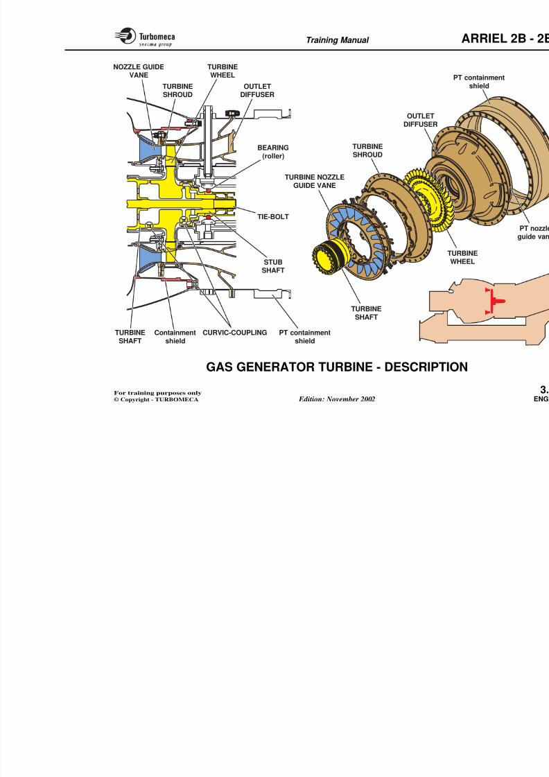
GAS GENERATOR TURBINE - DESCRIPTION
The gas generator turbine assembly (part of module M03)
includes rotating components and stationary components.
Rotating components
The main rotating component is the turbine wheel.
The turbine wheel consists of a disc and fir-tree mounted,single crystal blades.
At the front, the wheel is coupled by a curvic-coupling tothe turbine shaft . At the rear, the wheel is coupled to a stubshaft.
The rear part is supported by a roller bearing. Rotatinglabyrinths provide sealing.
A tie-bolt secures the rotating assembly.
Stationary components
The main stationary components avane, the turbine shroud and the exh
The nozzle guide vane includes a row bolted to the combustion chamber icontainment shield.
The turbine shroudaccommodates theand the containment shield. It is boltevane and to the inner flange of the tu
The outlet diffuser ensures the gas flgenerator and the power turbine. Its inlocation for the rear bearing. It also inturbine nozzle guide vane.
The power turbine containment shielddiffuser is part of the module M03.
8/13/2019 Arriel_2B-2B1 11-02 En
http://slidepdf.com/reader/full/arriel2b-2b1-11-02-en 70/461
Training Manual ARR
NOZZLE GUIDEVANE
TURBINESHROUD
TURBINEWHEEL
OUTLETDIFFUSER
BEARING
(roller)
STUBSHAFT
TIE-BOLT
TURBINESHAFT
TURBINEWHEEL
TURBINE NOZZLEGUIDE VANE
TURBINE
SHROUD
OUTLETDIFFUSER
PT containshield
Training Manual ARR
8/13/2019 Arriel_2B-2B1 11-02 En
http://slidepdf.com/reader/full/arriel2b-2b1-11-02-en 71/461
Training Manual ARR
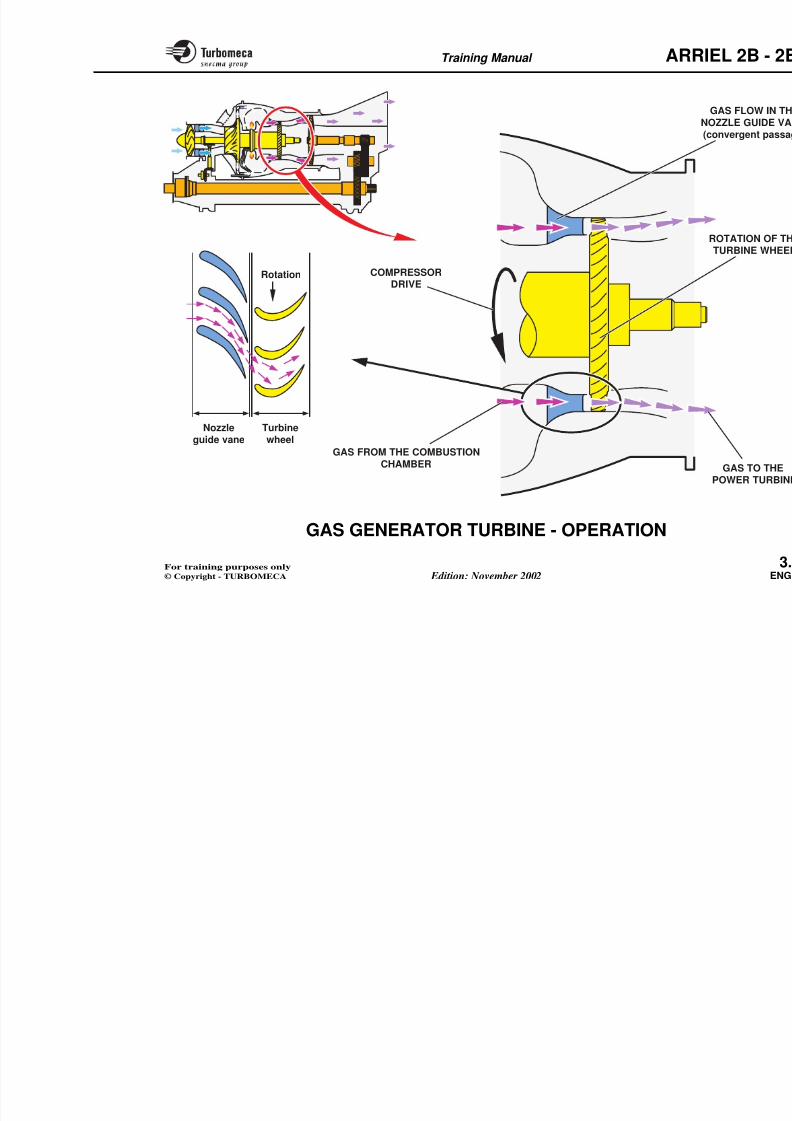
GAS GENERATOR TURBINE - OPERATION
The gas generator turbine transforms the gas energy into
mechanical power to drive the compressors and variousaccessories.
The operation is characterized by the first phase of expansion.
Turbine gas flow
The burnt gas first flows through the nozzle guide vanes.The gas velocity increases due to the convergent passage.
The flow on the blades results in aerodynamic forceswhose resultant causes the rotation of the wheel.
The gas, still containing energy, is directed to the powerturbine.

8/13/2019 Arriel_2B-2B1 11-02 En
http://slidepdf.com/reader/full/arriel2b-2b1-11-02-en 72/461
Training Manual ARR
COMPRESSORDRIVE
GAS FROM THE COMBUSTION
CHAMBER
Nozzleguide vane
Turbinewheel
Rotation
Training Manual ARR
8/13/2019 Arriel_2B-2B1 11-02 En
http://slidepdf.com/reader/full/arriel2b-2b1-11-02-en 73/461
Training Manual ARR
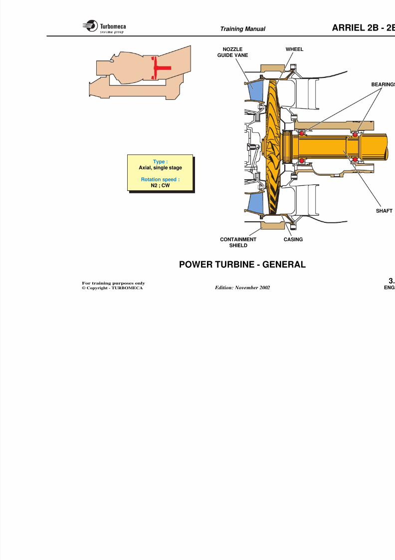
POWER TURBINE - GENERAL
FunctionThe turbine extracts the energy from the gas to drive thepower shaft through the reduction gearbox.
Position
- Between the gas generator and the reduction gearbox.
It forms the module M04.
Main characteristics
- Type : axial, single-stage
- Rotation speed : N2 ; CW.
Main components- Rotating components (wheel, shaf
- Stationary components (nozzle guidshield, casing).
8/13/2019 Arriel_2B-2B1 11-02 En
http://slidepdf.com/reader/full/arriel2b-2b1-11-02-en 74/461
Training Manual ARR
Type :Axial, single stage
Rotation speed :N2 ; CW
NOZZLE
GUIDE VANE
WHEEL
Training Manual ARR
8/13/2019 Arriel_2B-2B1 11-02 En
http://slidepdf.com/reader/full/arriel2b-2b1-11-02-en 75/461
g
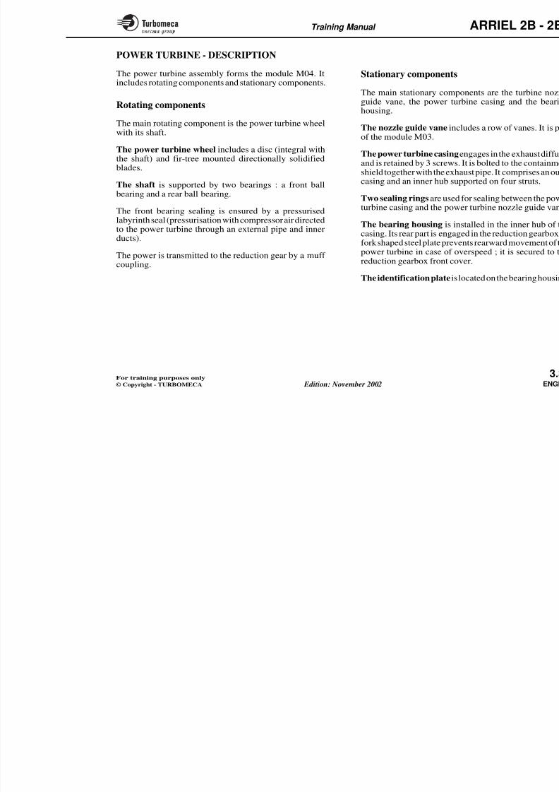
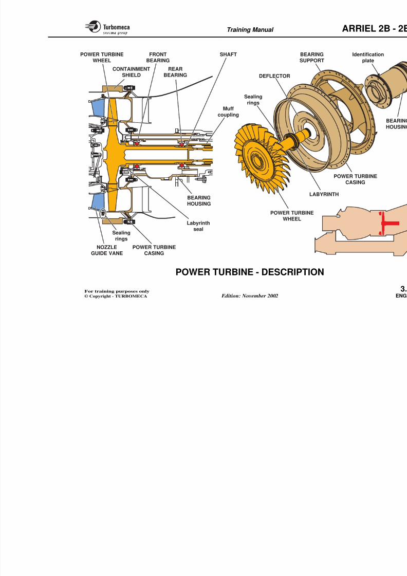
POWER TURBINE - DESCRIPTION
The power turbine assembly forms the module M04. It
includes rotating components and stationary components.
Rotating components
The main rotating component is the power turbine wheelwith its shaft.
The power turbine wheel includes a disc (integral with
the shaft) and fir-tree mounted directionally solidifiedblades.
The shaft is supported by two bearings : a front ballbearing and a rear ball bearing.
The front bearing sealing is ensured by a pressurisedlabyrinth seal (pressurisation with compressor air directed
to the power turbine through an external pipe and innerducts).
The power is transmitted to the reduction gear by a muff coupling.
Stationary components
The main stationary components arguide vane, the power turbine casihousing.
The nozzle guide vane includes a roof the module M03.
The power turbine casing engages inand is retained by 3 screws. It is bolteshield together with the exhaust pipe. casing and an inner hub supported o
Two sealing rings are used for sealinturbine casing and the power turbine
The bearing housing is installed in
casing. Its rear part is engaged in the rfork shaped steel plate prevents rearwpower turbine in case of overspeed reduction gearbox front cover.
The identification plate is located on
8/13/2019 Arriel_2B-2B1 11-02 En
http://slidepdf.com/reader/full/arriel2b-2b1-11-02-en 76/461
Training Manual ARR
IdeFRONT
BEARING
REARBEARING
SHAFT
Muff
coupling
Labyrinthseal
BEARINGHOUSING
POWER TURBINE
WHEEL
CONTAINMENTSHIELD
BEARING
SUPPORT
POWER TUCASIN
LABYRINTH
POWER TURBINEWHEEL
DEFLECTOR
Sealingrings
Sealing
rings
Training Manual ARR
8/13/2019 Arriel_2B-2B1 11-02 En
http://slidepdf.com/reader/full/arriel2b-2b1-11-02-en 77/461
g
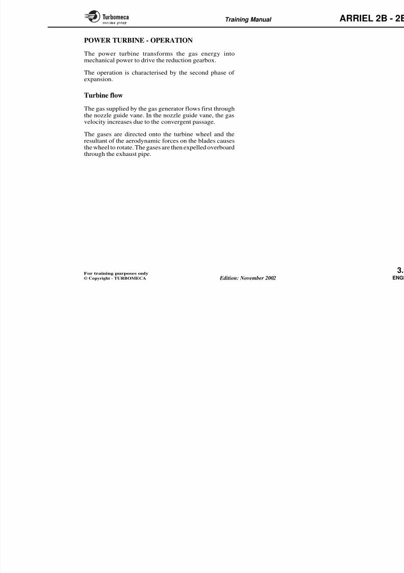
POWER TURBINE - OPERATION
The power turbine transforms the gas energy into
mechanical power to drive the reduction gearbox.
The operation is characterised by the second phase of expansion.
Turbine flow
The gas supplied by the gas generator flows first through
the nozzle guide vane. In the nozzle guide vane, the gasvelocity increases due to the convergent passage.
The gases are directed onto the turbine wheel and theresultant of the aerodynamic forces on the blades causesthe wheel to rotate. The gases are then expelled overboardthrough the exhaust pipe.
8/13/2019 Arriel_2B-2B1 11-02 En
http://slidepdf.com/reader/full/arriel2b-2b1-11-02-en 78/461
Training Manual ARR
RNozzle
guide vaneTurbinewheel
Rotation
GAS FROM THE
FLOW IN THE
NOZZLE GUIDE VANE
Training Manual ARR
8/13/2019 Arriel_2B-2B1 11-02 En
http://slidepdf.com/reader/full/arriel2b-2b1-11-02-en 79/461
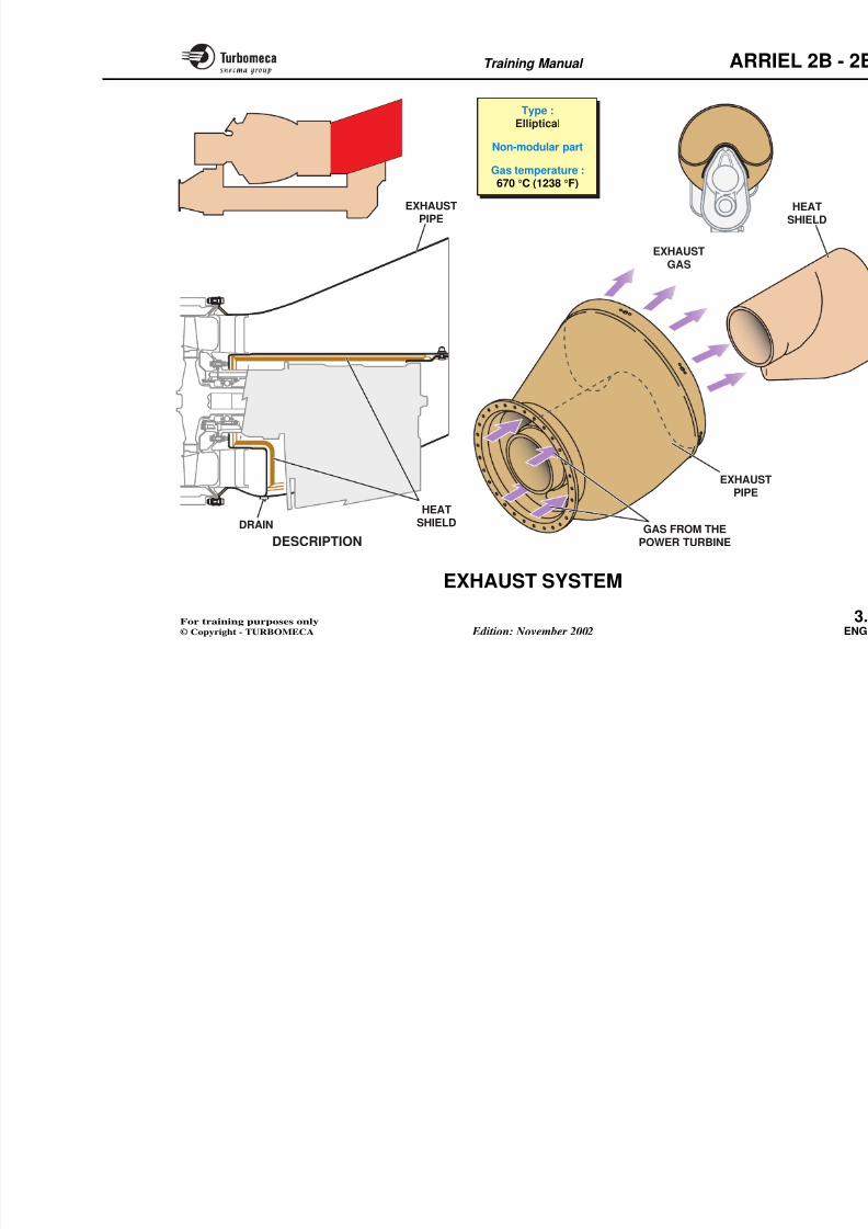
EXHAUST SYSTEM
FunctionThe exhaust pipe continues the expansion phase andexpels the gas overboard.
Position
- Behind the power turbine, around the reduction gear.
Main characteristics
- Type : elliptical
- Non-modular part
- Gas temperature : 670 °C (1238 °F).
Main components
- Exhaust pipe
- Heat shield.
Note : The exhaust pipe is considered to be an SRU (Shop Replaceable Unit).
Description
The exhaust pipe, which has an ellipfrom stainless steel. It is bolted to thpower turbine casing with the contai
A heat shield is fitted between the ereduction gearbox to protect the gearbheat.
The exhaust pipe has a drain at the b
Operation
Functionally it should be noted that contains a certain amount of energsmall residual thrust.
8/13/2019 Arriel_2B-2B1 11-02 En
http://slidepdf.com/reader/full/arriel2b-2b1-11-02-en 80/461
Training Manual ARR
EXHAUSTPIPE
EXHAUSTGAS
HEAT
EXHAUSTPIPE
Type :
Elliptical
Non-modular part
Gas temperature :670 °C (1238 °F)
Training Manual ARR
8/13/2019 Arriel_2B-2B1 11-02 En
http://slidepdf.com/reader/full/arriel2b-2b1-11-02-en 81/461
REDUCTION GEARBOX - GENERAL
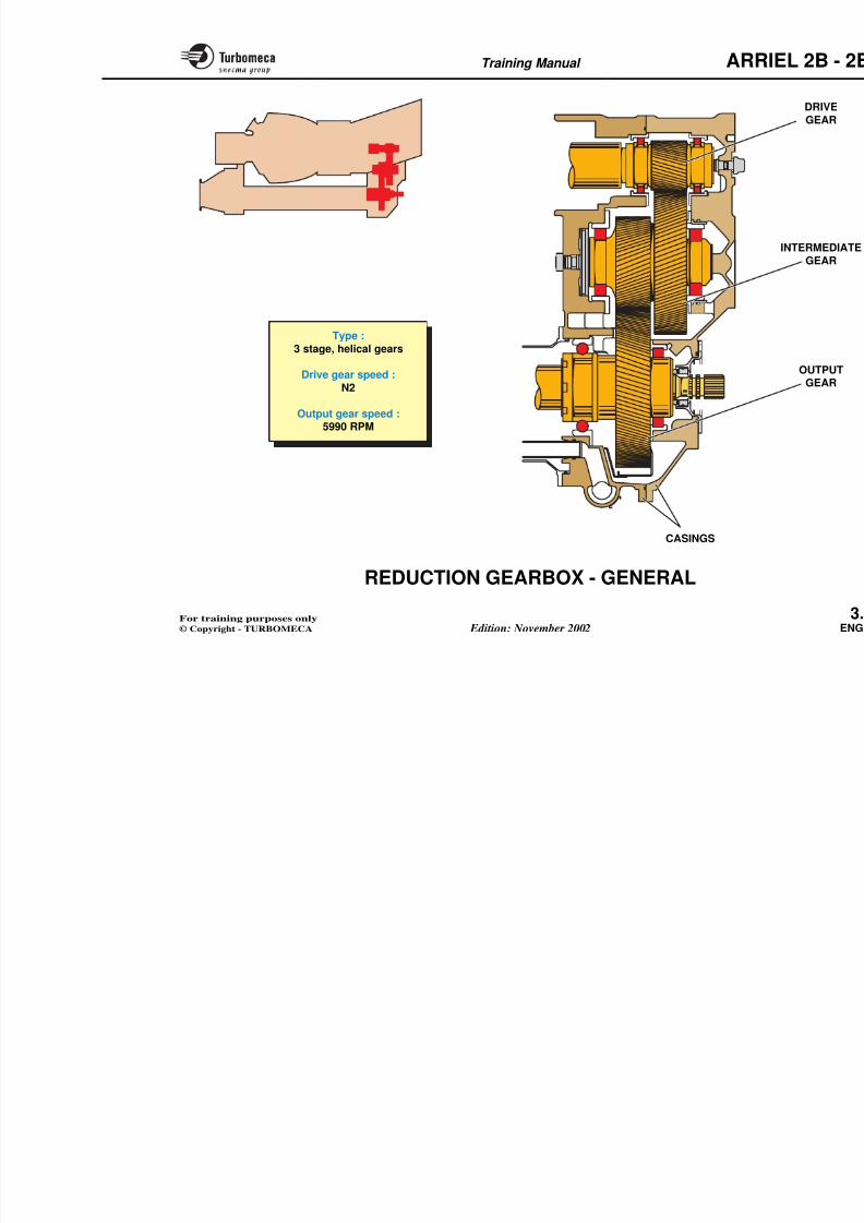
FunctionThe reduction gearbox provides a reduced speed outputand transmits the drive forwards.
Position
- At the rear of the engine
- It forms the module M05.
Main characteristics
- Type : 3 stage, helical gears
- Drive gear speed : N2
- Output gear speed : 5990 RPM.
Main components- Drive gear
- Intermediate gear
- Output gear
- Casings.
8/13/2019 Arriel_2B-2B1 11-02 En
http://slidepdf.com/reader/full/arriel2b-2b1-11-02-en 82/461
Training Manual ARR
Type :
3 stage, helical gears
Drive gear speed :
N2
Output gear speed :5990 RPM
Training Manual ARR
8/13/2019 Arriel_2B-2B1 11-02 En
http://slidepdf.com/reader/full/arriel2b-2b1-11-02-en 83/461
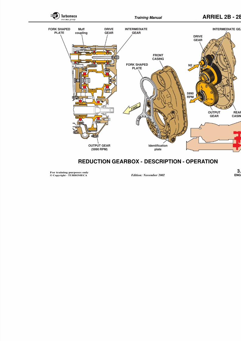
REDUCTION GEARBOX - DESCRIPTION -
OPERATION
The reduction gearbox module mainly includes threegears contained in two half casings.
Drive gear
The drive gear is driven by the power turbine through amuff coupling. It is supported by two roller bearings.
Intermediate gear
The intermediate gear is a double helical type gear : onegear meshes with the drive gear, the other one with theoutput gear. The intermediate gear is supported by tworoller bearings. A piston is fitted to the intermediate gearwith its head located in the gearbox front casing. It is
supplied with oil pressure to balance the load on the gear.
Output gear
The output gear is a simple gear supported by a ball bearingat the front and a roller bearing at the rear.
The hub is internally splined to receive the transmissionshaft. It rotates at 5990 RPM.
Note : The output gear is also used as a phonic wheel for detection of power turbine rotation speed. Refer to
Reduction gearbox casing
The gears are housed in a light alloy ccasings). A fork shaped steel plate is mface of the casing to prevent rearwapower turbine in the event of oversp
The module identification plate is locthe casing.
Operation of the reduction gear
The reduction gear provides a forwareduced speed.
The drive gear is directly driven by the(muff coupling drive). It transmits tintermediate gear.
The intermediate gear drives the outputhe power drive at a speed of approxclockwise.
8/13/2019 Arriel_2B-2B1 11-02 En
http://slidepdf.com/reader/full/arriel2b-2b1-11-02-en 84/461
Training Manual ARR
DRIVEGEAR
INTERMEDIATEGEAR
Muffcoupling
FORK SHAPEDPLATE
FRONTCASING
FORK SHAPED
PLATE
I
DRIVEGEAR
OUTGE
N2
5990RPM
FWD
Training Manual ARR
8/13/2019 Arriel_2B-2B1 11-02 En
http://slidepdf.com/reader/full/arriel2b-2b1-11-02-en 85/461
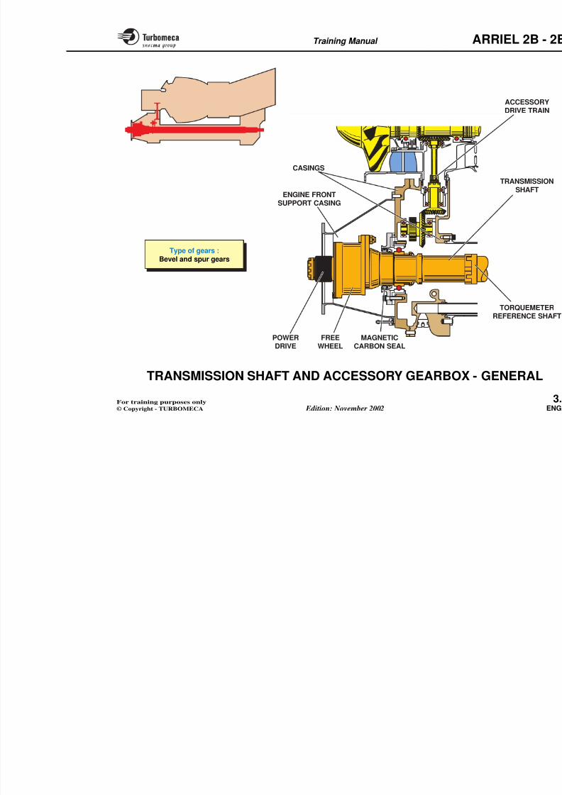
TRANSMISSION SHAFT AND ACCESSORY
GEARBOX - GENERAL
Function
The shaft transmits the power to the front of the engine.
The accessory gearbox provides the drive for the engineaccessories.
Position
- Shaft beneath the engine
- Accessory gearbox at the front of the engine
- This assembly forms the module M01.
Main characteristics
- Type of gears : bevel and spur gears.
Main components
- Transmission shaft
- Torquemeter reference shaft
- Free wheel
- Power drive
- Accessory drive train
- Casings
- Engine front support casing.
Note 1 : The alternator drive gear awheel for detection of the gaspeed. Refer to "MEA
INDICATING SYSTEMS"details.
Note 2 : The transmission shaftorquemeter. Refer to "ME INDICATING SYSTEMS"d t il
8/13/2019 Arriel_2B-2B1 11-02 En
http://slidepdf.com/reader/full/arriel2b-2b1-11-02-en 86/461
Training Manual ARR
8/13/2019 Arriel_2B-2B1 11-02 En
http://slidepdf.com/reader/full/arriel2b-2b1-11-02-en 87/461
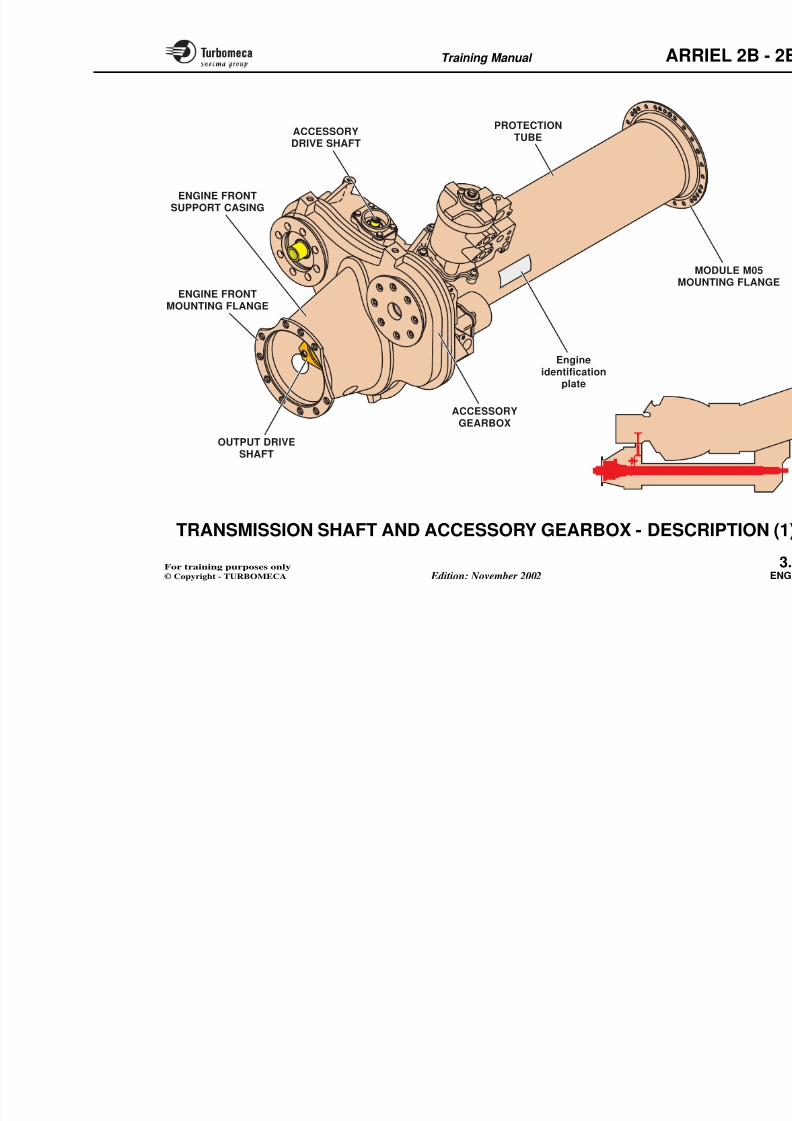
TRANSMISSION SHAFT AND ACCESSORY
GEARBOX - DESCRIPTION (1)
The module M01 comprises mainly the output shaftprotection tube, the accessory gearbox and the enginefront support. It is this module which provides the rigidityof the engine.
At the rear of the protection tube is the flange for attachmentto module M05.
The accessory gearbox is provided with mounting flangesfor various accessories.
The engine front support casing is bolted to the accessorygearbox front face.
The output drive shaft is located in the engine front supportcasing.
The engine front support casing is installed on the frontface of the gearbox.
The module identification plate is located on the protectiontube right hand side.
The engine identification plate is located on the protectiontube left hand side.
ARR
8/13/2019 Arriel_2B-2B1 11-02 En
http://slidepdf.com/reader/full/arriel2b-2b1-11-02-en 88/461
Training Manual ARR
MMOU
Engineidentification
plate
ACCESSORYGEARBOX
PROTECTIONTUBE
ENGINE FRONTMOUNTING FLANGE
ENGINE FRONTSUPPORT CASING
OUTPUT DRIVESHAFT
ACCESSORYDRIVE SHAFT
Training Manual ARR
8/13/2019 Arriel_2B-2B1 11-02 En
http://slidepdf.com/reader/full/arriel2b-2b1-11-02-en 89/461
TRANSMISSION SHAFT AND ACCESSORY
GEARBOX - DESCRIPTION (2)
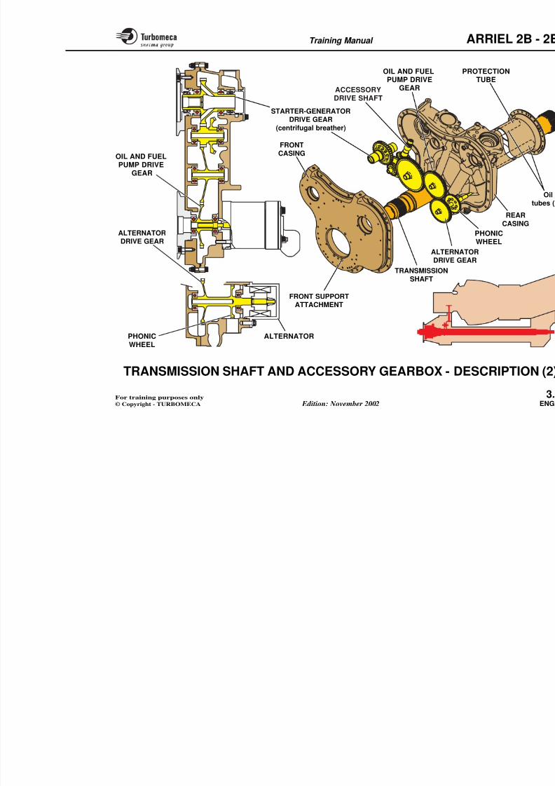
Transmission shaft
The shaft assembly takes the drive from the reduction gearto the accessory gearbox. The shaft itself is located in aprotection tube bolted to the reduction gearbox at the rearand to the accessory gearbox at the front. The front of theshaft is supported by a ball bearing. The power drive flange
is mounted on the shaft splines. Sealing of the oil whichlubricates the bearing is ensured by a carbon seal.
Three oil tubes are located in the protection tube.
Accessory gearbox
The gearbox assembly includes a traia light alloy casing. The gearbox is inscompressor by means of four bolts.
The front face of the gearbox accommdrives:
- Starter-generator
- Fuel pumps
- Main output drive.
The rear face of the gearbox accomm
drives:
- Oil pumps
- Alternator.
ARR
8/13/2019 Arriel_2B-2B1 11-02 En
http://slidepdf.com/reader/full/arriel2b-2b1-11-02-en 90/461
Training Manual ARR
PROTEC
TUB
OIL AND FUELPUMP DRIVE
GEAR
FRONT SUPPORT
ATTACHMENT
ALTERNATORDRIVE GEAR
PHOWHE
OIL AND FUEL
PUMP DRIVEGEARACCESSORYDRIVE SHAFT
FRONTCASING
ALTERNATORDRIVE GEAR
TRANSMISSIONSHAFT
STARTER-GENERATORDRIVE GEAR
(centrifugal breather)
Training Manual ARR
8/13/2019 Arriel_2B-2B1 11-02 En
http://slidepdf.com/reader/full/arriel2b-2b1-11-02-en 91/461
TRANSMISSION SHAFT AND ACCESSORY
GEARBOX - DESCRIPTION (3)
Function
The shaft transmits the power from the reduction gearboxto the helicopter.
Position
Lower part of the engine.
Main characteristics
- Hollow steel shaft with co-axial output shaft
- Drive through freewheel unit.
Main components
- Transmission shaft
- Protection tube
- Output shaft
- Freewheel unit.
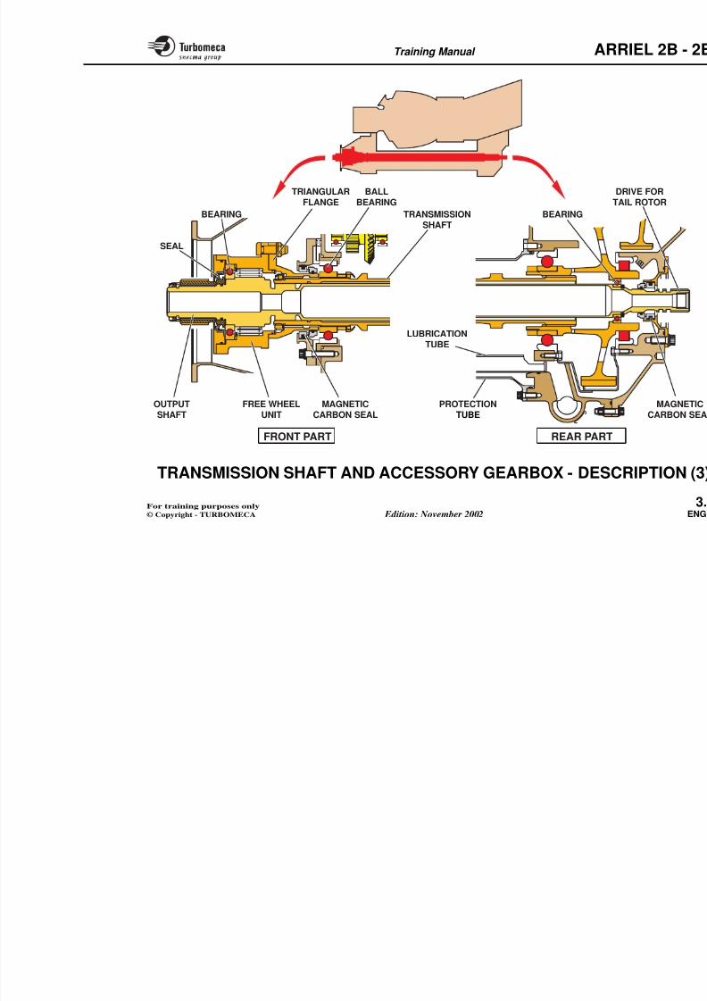
Description
The front of the transmission shaft isbearing in the accessory gearbox areduction gearbox output gear. Secarbon magnetic seal at the front and
A triangular flange is fitted on the sfreewheel unit is mounted on the flaaxial output shaft which in turn drivegearbox and tail rotor.
The output shaft is supported at the frflange and at the rear by a bearingreduction gearbox output gear.
Three oil tubes are fitted inside thetransmit oil between the reduction and
Operation
The transmission shaft drives the outfreewheel unit to drive the MGB and tof autorotation the free wheel diseng
Note : The freewheel unit and shaft a
ARR
8/13/2019 Arriel_2B-2B1 11-02 En
http://slidepdf.com/reader/full/arriel2b-2b1-11-02-en 92/461
Training Manual ARR
BEARING
SEAL
TRIANGULAR
FLANGE
FREE WHEELUNIT
OUTPUTSHAFT
TRANSMISSIONSHAFT
BALL
BEARING
MAGNETICCARBON SEAL
BEARING
DR
TA
PROTECTIONTUBE
LUBRICATIONTUBE
Training Manual ARR
8/13/2019 Arriel_2B-2B1 11-02 En
http://slidepdf.com/reader/full/arriel2b-2b1-11-02-en 93/461
TRANSMISSION SHAFT AND ACCESSORY
GEARBOX - DESCRIPTION (4)
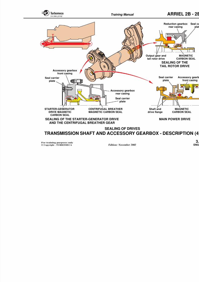
Sealing of drives
Sealing of the various drives is ensured by seals fittedeither in the support casing or in the accessory.
Main power drive
This is ensured by a magnetic carbon seal fitted in theaccessory gearbox front casing.
Tail rotor drive
This is ensured by a magnetic carbon seal fitted in thereduction gearbox rear casing.
Starter-generator drive
A magnetic carbon seal is fitted in a support on the gearboxfront casing.
Centrifugal breather gear (rear half of the starter-
generator gear)
Sealed by a magnetic carbon seal mounted in a support on
the rear face of the gearbox.
Note 1 : Fuel pump drive
Seals fitted in the fuel pumpSYSTEM")
Note 2 : Alternator drive
No seal on the drive shaft.
is sealed by an O'ring on (see "ELECTRICAL SYST
Note 3 : Oil pump drive
No seal on the drive shaft. Athe mounting flange (see "
T i i M l ARR
8/13/2019 Arriel_2B-2B1 11-02 En
http://slidepdf.com/reader/full/arriel2b-2b1-11-02-en 94/461
Training Manual ARR
MCAShaft anddrive flange
SEALING OF THE STARTER GENERATOR DRIVE
SEALING TAIL ROTO
MAIN POWE
Seal carrierplate
STARTER-GENERATORDRIVE MAGNETICCARBON SEAL
CENTRIFUGAL BREATHERMAGNETIC CARBON SEAL
Accessory gearboxfront casing
Accessory gearboxrear casing
Reductionrear ca
Seal carrierplate
Seal carrierplate
Output gear andtail rotor drive
Training Manual ARR
8/13/2019 Arriel_2B-2B1 11-02 En
http://slidepdf.com/reader/full/arriel2b-2b1-11-02-en 95/461
TRANSMISSION SHAFT AND ACCESSORY
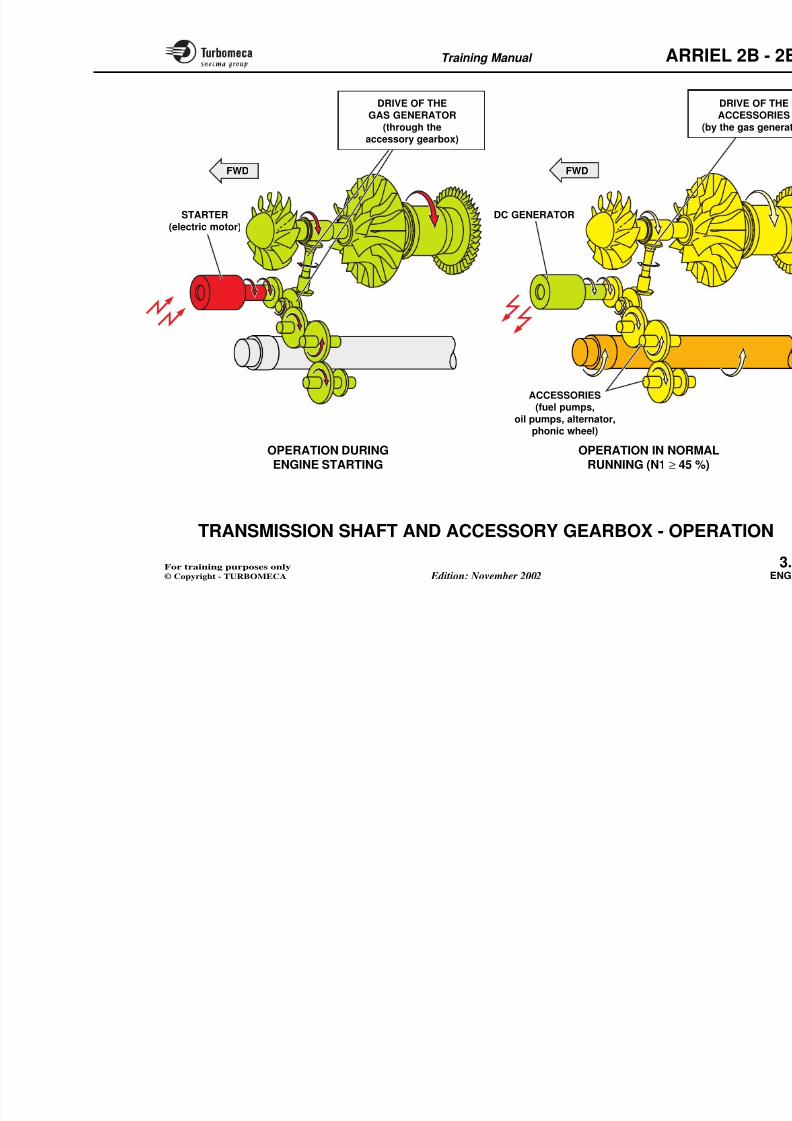
GEARBOX - OPERATION
The operation is considered during engine starting and innormal running.
Operation during engine starting
During starting, the starter motor drives the accessorygearbox and thus the gas generator rotating assembly.
The compressor supplies air to the combustion chamberand the starting sequence continues.
Operation in normal running
At self-sustaining speed (approximelectrical supply to the starter motor The starter motor is then mechaniengine and operates as a generator toto the aircraft electrical system.
The gas generator drives the accessothe bevel gear located between the athe centrifugal compressor.
The following accessories are driven
- Starter-generator
- Fuel pumps
- Oil pumps
- Alternator / phonic wheel.
T i i M l ARR
8/13/2019 Arriel_2B-2B1 11-02 En
http://slidepdf.com/reader/full/arriel2b-2b1-11-02-en 96/461
Training Manual ARR
OPERATION DURINGENGINE STARTING
STARTER
(electric motor)
DC GENERATOR
FWD
OPERATION IN NORMRUNNING (N1 ≥ 45 %
ACCESSORIES(fuel pumps,
oil pumps, alternator,phonic wheel)
FWD
DRIVE OF THE
GAS GENERATOR(through theaccessory gearbox)
8/13/2019 Arriel_2B-2B1 11-02 En
http://slidepdf.com/reader/full/arriel2b-2b1-11-02-en 97/461
Training Manual ARR
8/13/2019 Arriel_2B-2B1 11-02 En
http://slidepdf.com/reader/full/arriel2b-2b1-11-02-en 98/461
Training Manual ARR
4-OIL SYSTEM
- Oil system (79-00-00) ..................................................... 4
- Oil tank .......................................................................... 4
- Oil pumps (79-24-00) .................................................... 4
- Oil valve assembly (79-25-00) ....................................... 4- Oil filter and heat exchanger (72-61-00)...................... 4
- Filter pre-blockage indicator (72-61-00)...................... 4
- Oil cooler ....................................................................... 4
- Centrifugal breather (79-00-00) ................................... 4- Electrical magnetic plug (79-38-00) ............................. 4
- Mechanical magnetic plugs (72-15-00) and (72-61-00) 4
- Scavenge strainers (72-61-00)....................................... 4
- Low oil pressure switch (79-31-00) .............................. 4- Oil pressure transmitter 4
Training Manual ARR
8/13/2019 Arriel_2B-2B1 11-02 En
http://slidepdf.com/reader/full/arriel2b-2b1-11-02-en 99/461
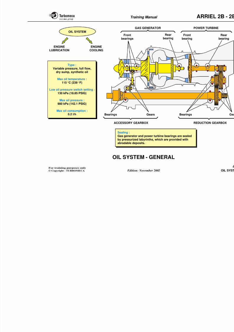
OIL SYSTEM - GENERAL
Function
The oil system ensures lubrication and cooling of theengine.
Position
All the components are fitted on the engine except the tank
and cooler.
Main characteristics
- System type : variable pressure, full flow, dry sump,synthetic oil
- Max oil temperature : 115 °C (239 °F)
- Min oil pressure switch setting : 130 kPa (18.85 PSIG)
- Low oil pressure : 980 kPa (142.1 PSIG)
- Max oil consumption : 0.2 l/h.
Lubrication requirementsLubrication is required for the follow
- Gas generator front bearings
• Axial compressor bearing
• Centrifugal compressor bearing
• Accessory drive bearings
- Gas generator rear bearing
- Power turbine bearings
- Reduction gearbox
- Accessory gearbox.
Sealing
Gas generator and power turbine bepressurized labyrinths, which are prodeposits.
Training Manual ARR
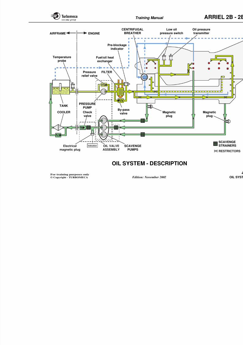
8/13/2019 Arriel_2B-2B1 11-02 En
http://slidepdf.com/reader/full/arriel2b-2b1-11-02-en 100/461
Training Manual ARR
REDUCTIO
Type :
Variable pressure, full flow,dry sump, synthetic oil
Max oil temperature :
115 °C (239 °F)
Low oil pressure switch setting :
130 kPa (18.85 PSIG)
Max oil pressure :980 kPa (142.1 PSIG)
Max oil consumption :0.2 l/h
Frontbearings
Rearbearing
Frontbearing
POWER TGAS GENERATOR
Bearings Gears
ACCESSORY GEARBOX
Bearings
OIL SYSTEM
ENGINELUBRICATION
ENGINECOOLING
Sealing :Gas generator and power turbine bearings are sealed
by pressurized labyrinths which are provided with
Training Manual ARR
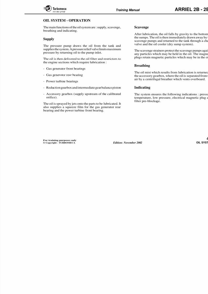
8/13/2019 Arriel_2B-2B1 11-02 En
http://slidepdf.com/reader/full/arriel2b-2b1-11-02-en 101/461
OIL SYSTEM - DESCRIPTION
The system contains all the components necessary for
engine lubrication : tank, pumps, filter, cooler, breatherand indicating devices.
Oil tank
The oil tank contains the volume of oil required to lubricatethe engine. It is supplied by the aircraft manufacturer.
Oil pumps
The oil pump pack contains one pressure pump and threescavenge pumps. The gerotor type pumps are driven by theaccessory gearbox. The pressure pump is equipped with apressure relief valve.
Oil valve assemblyThe oil valve assembly houses a check valve, an electricalmagnetic plug and the strainer for the gas generator rearbearing.
Oil filter
The oil filter retains any particles which may be present inthe oil. It is provided with a by-pass valve and a pre-blockage indicator. It also forms a heat exchanger with the
Scavenge strainers
The scavenge strainers protect the scdebris in the system.
Magnetic plugs
Mechanical magnetic plugs are fittscavenge pumps. An electrical mag
the scavenge outlet.
Oil cooler
The air cooled oil cooler cools the oilaircraft manufacturer.
Centrifugal breatherThe centrifugal breather separates thmist and vents the system.
Indicating devices
- Oil temperature probe
- Low oil pressure switch
Oil t itt
Training Manual ARR
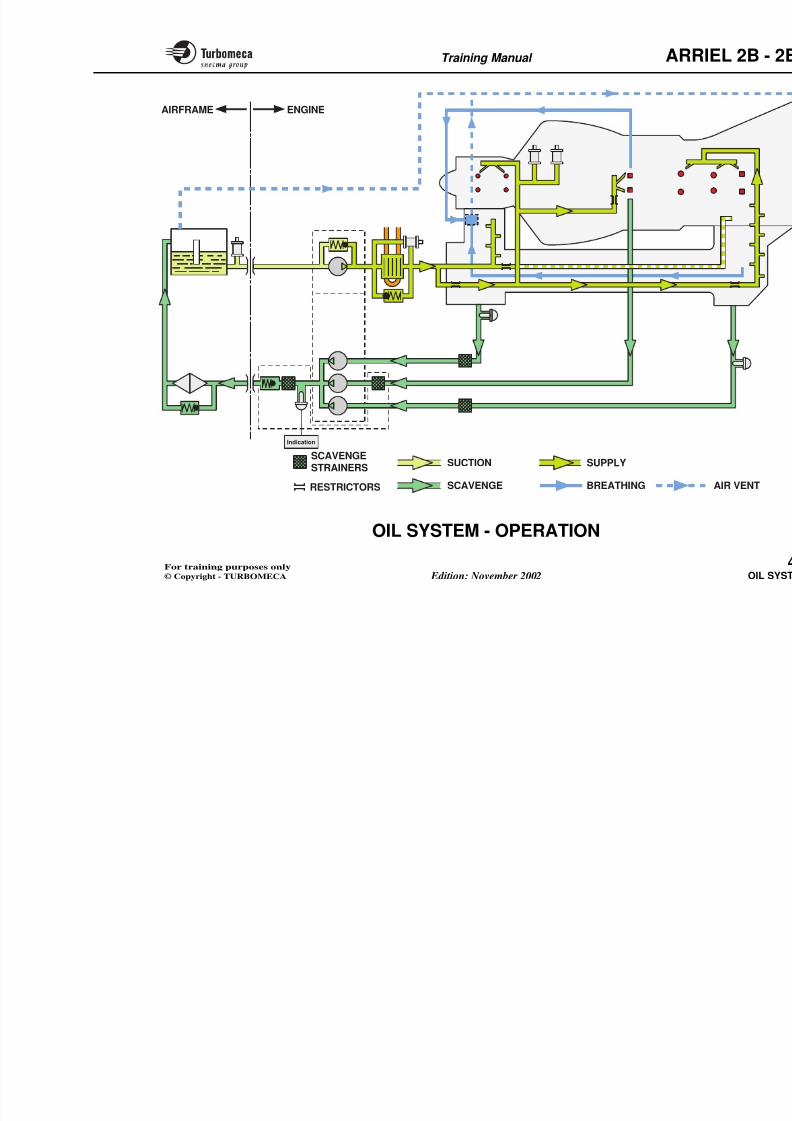
8/13/2019 Arriel_2B-2B1 11-02 En
http://slidepdf.com/reader/full/arriel2b-2b1-11-02-en 102/461
Training Manual ARR
ENGINEAIRFRAME
Pressure
relief valve
Pre-blockage
indicator
Low oil
pressure switch
Oil pressure
transmitter
Magnetic
plug
Magnetic
plug
COOLER
TANK
Temperatureprobe
Check
valve
FILTER
By-pass
valve
PRESSURE
PUMP
Fuel/oil heatexchanger
CENTRIFUGAL
BREATHER
8/13/2019 Arriel_2B-2B1 11-02 En
http://slidepdf.com/reader/full/arriel2b-2b1-11-02-en 103/461
Training Manual ARR
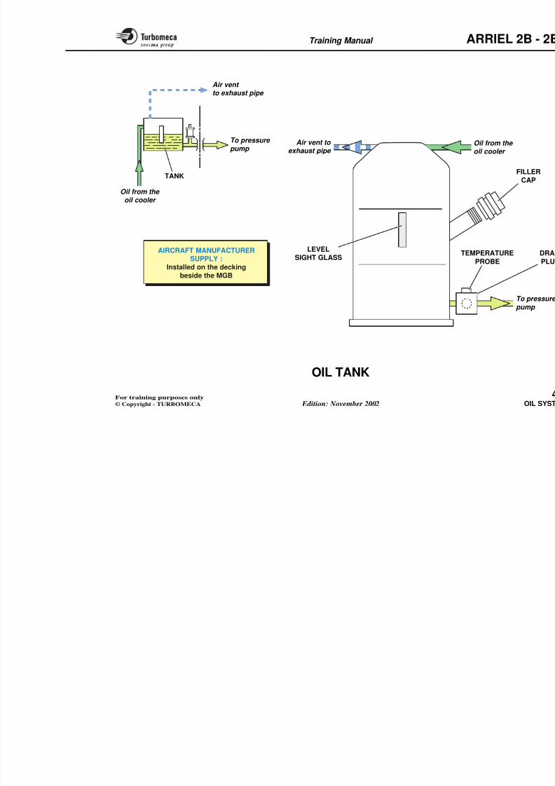
8/13/2019 Arriel_2B-2B1 11-02 En
http://slidepdf.com/reader/full/arriel2b-2b1-11-02-en 104/461
Training Manual ARR
Indication
ENGINEAIRFRAME
SCAVENGESTRAINERS
SUPPLYSUCTION
Training Manual ARR
8/13/2019 Arriel_2B-2B1 11-02 En
http://slidepdf.com/reader/full/arriel2b-2b1-11-02-en 105/461
OIL TANK
Function
The tank contains the oil required for engine lubrication.
Position
- In the system : between the oil cooler and the pressurepump
- On the aircraft : it is installed on the decking beside theMGB.
Main characteristics
- Aircraft manufacturer supply.
Main components
- Filler cap
- Level sight glass
- Drain plug
- Temperature probe
- Unions (supply, return and vent)
- Fan thermostatic switch.
Note : Refer to the aircraft manuaand operation.
Training Manual ARR
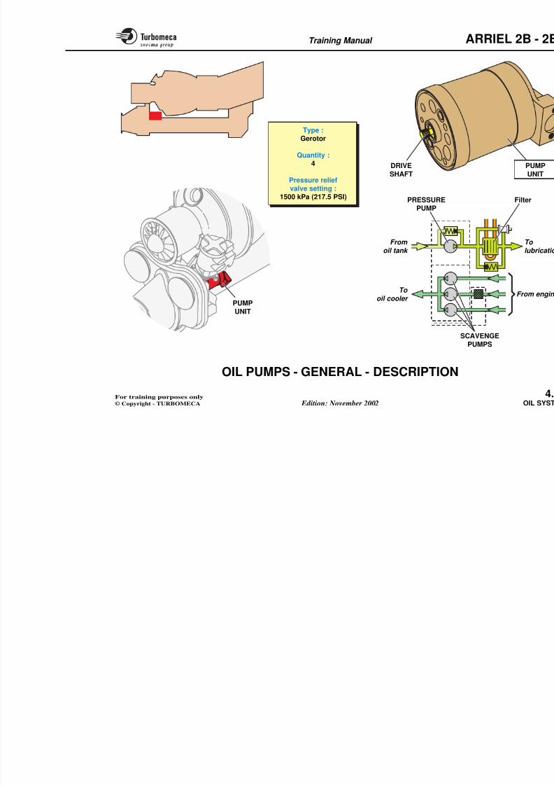
8/13/2019 Arriel_2B-2B1 11-02 En
http://slidepdf.com/reader/full/arriel2b-2b1-11-02-en 106/461
Training Manual ARR
AIRCRAFT MANUFACTURERSUPPLY :
Installed on the decking
beside the MGB
LEVELSIGHT GLASS
Air vent to exhaust pipe
To pressure
pump
Air vent to exhaust pipe
Oil from the oil cooler
TANK
TEMPERA
PROB
Oil frooil co
Training Manual ARR
8/13/2019 Arriel_2B-2B1 11-02 En
http://slidepdf.com/reader/full/arriel2b-2b1-11-02-en 107/461
OIL PUMPS - GENERAL - DESCRIPTION
Function
The pumps ensure oil circulation.
Position
- In the system: on engine oil system inlet and outlet.
- On the engine: the pump unit is mounted by bolts on therear face of the accessory gearbox.
Main characteristics
- Type : gerotor
- Quantity : 4
- Pressure relief valve setting : 1500 kPa (217.5 PSI).
Description
The pump unit comprises a body co(one pressure pump with pressurescavenge pumps).
The four pumps are driven by meanconnected to the accessory drive (N1
Training Manual ARR
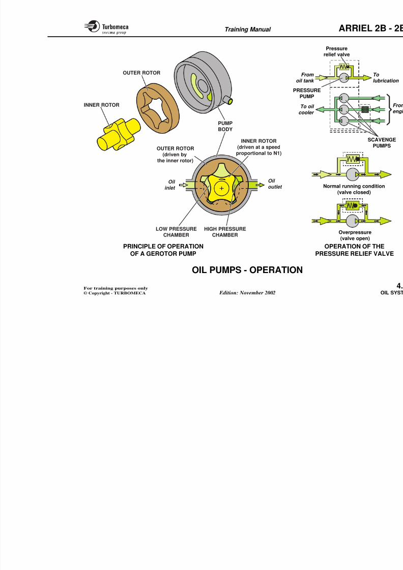
8/13/2019 Arriel_2B-2B1 11-02 En
http://slidepdf.com/reader/full/arriel2b-2b1-11-02-en 108/461
g
Type :Gerotor
Quantity :4
Pressure relief
valve setting :1500 kPa (217.5 PSI)
DRIVE
SHAFT
PUMP
UNIT
PRESSUREPUMP
From
oil tank
To
oil cooler
Training Manual ARR
8/13/2019 Arriel_2B-2B1 11-02 En
http://slidepdf.com/reader/full/arriel2b-2b1-11-02-en 109/461
OIL PUMPS - OPERATION
Operating principle of a gerotor pump
A gerotor pump is a pump which comprises an inner rotordriving an outer rotor.
The inner rotor is eccentric to the outer rotor and has oneless lobe than the outer rotor has spaces.
Because of the eccentricity, the size of the chambers
formed between the two rotors varies with rotation.
Thus the oil is drawn in as the low pressure chamber sizeis increasing and is forced out under pressure as the highpressure chamber size decreases.
The process is continuous for each chamber, ensuring asmooth, positive flow.
Operation of the pressure pump
The pressure pump draws the oil from the tank and forcesit out under pressure in the supply system.
The whole pump flow is used (full flow ; pressure isfunction of the rotation speed, oil viscosity and oiltemperature).
Pressure relief valve operation
If the oil pressure exceeds the valve seand allows the oil to return to the pu
In normal operation the valve is closexceptional circumstances, e.g. startemperature.
Operation of the scavenge pump
Three scavenge pumps, one for the redfor the gas generator bearing, one bearings and the accessory gear trainoil cooler and the tank.
The pump flow is higher than that o
(dry sump type system).
Training Manual ARR
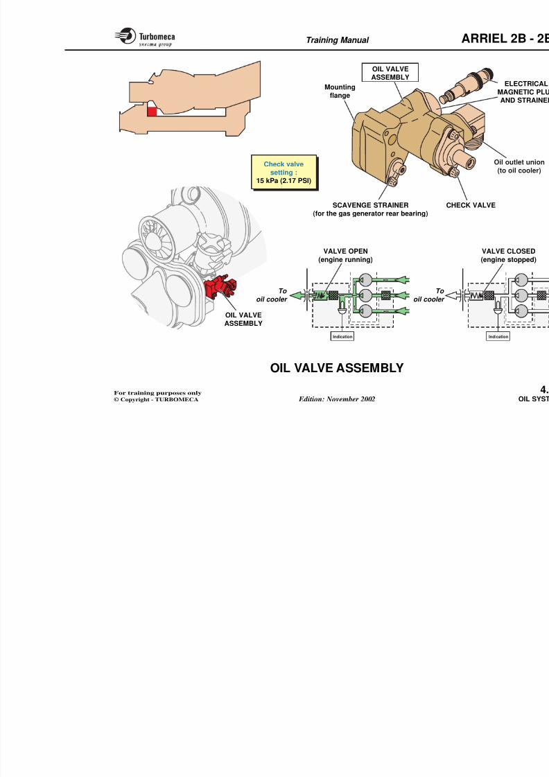
8/13/2019 Arriel_2B-2B1 11-02 En
http://slidepdf.com/reader/full/arriel2b-2b1-11-02-en 110/461
g
Normal runnin
(valve cl
Overpre
(valve o
Pressurerelief valve
PRESSURE
PUMP
From oil tank
To oil
cooler
Oil outlet
Oil
inlet
PUMP
BODY
HIGH PRESSURECHAMBER
LOW PRESSURECHAMBER
INNER ROTOR(driven at a speed
proportional to N1)
INNER ROTOR
OUTER ROTOR(driven by
the inner rotor)
OUTER ROTOR
Training Manual ARR
8/13/2019 Arriel_2B-2B1 11-02 En
http://slidepdf.com/reader/full/arriel2b-2b1-11-02-en 111/461
OIL VALVE ASSEMBLY
Function
The assembly houses a check valve and an electricalmagnetic plug and the strainer for the gas generator rearbearing.
The check valve prevents oil flow from the cooler to theengine when the pressure is very low (engine stopped).
The electrical magnetic plug collects ferrous particles
which may be in the oil.
Position
- In the system : downstream of the scavenge pumps
- On the engine : on the rear face of the accessory gearbox.
Main characteristics
- Check valve setting : 15 kPa (2.17 PSI).
Main components
- Check valve
- Electrical magnetic plug and strainer- Scavenge strainer for the gas generator rear bearing.
Check valve description
The check valve comprises :
- A piston
- A spring
- A cover.
Check valve operation
Engine running
The outlet pressure of the scavengepiston, compressing the spring thus cooler.
Engine stopped
The scavenge pump outlet pressure i
Spring pressure closes the valve anfrom the cooler into the engine.
Training Manual ARR
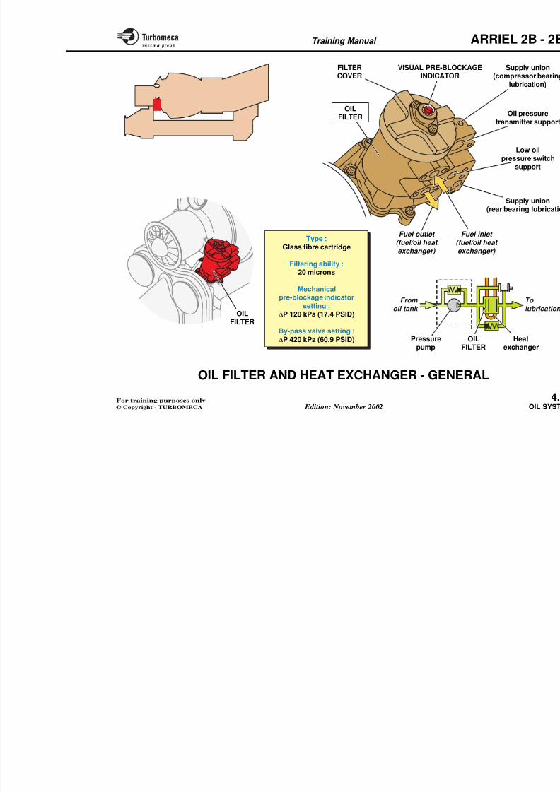
8/13/2019 Arriel_2B-2B1 11-02 En
http://slidepdf.com/reader/full/arriel2b-2b1-11-02-en 112/461
Check valvesetting :
15 kPa (2.17 PSI)
CHECK VALSCAVENGE STRAINER(for the gas generator rear bearing)
Mounting
flange
OIL VALVEASSEMBLY
OIL VALVE
ASSEMBLY
To
oil cooler
V
(e
To
oil cooler
VALVE OPEN
(engine running)
Training Manual ARR
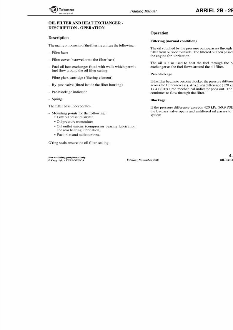
8/13/2019 Arriel_2B-2B1 11-02 En
http://slidepdf.com/reader/full/arriel2b-2b1-11-02-en 113/461
OIL FILTER AND HEAT EXCHANGER -
GENERAL
Function
The filter retains particles that may be in the oil. The filterhousing forms a fuel - oil heat exchanger.
Position
- In the system : downstream of the pressure pump
- On the engine : on the left rear face of the accessorygearbox.
Main characteristics
- Type : glass fibre cartridge
- Filtering ability : 20 microns
- Mechanical pre-blockage indicator setting : ∆P 120 kPa(17.4 PSID)
- By-pass valve setting : ∆P 420 kPa (60.9 PSID).
Main components
The filter contains the interchangeabaccessible by a cover, and the fuel -
It also provides the support for accesindicator, low oil pressure switch, oil outlet unions).
Training Manual ARR
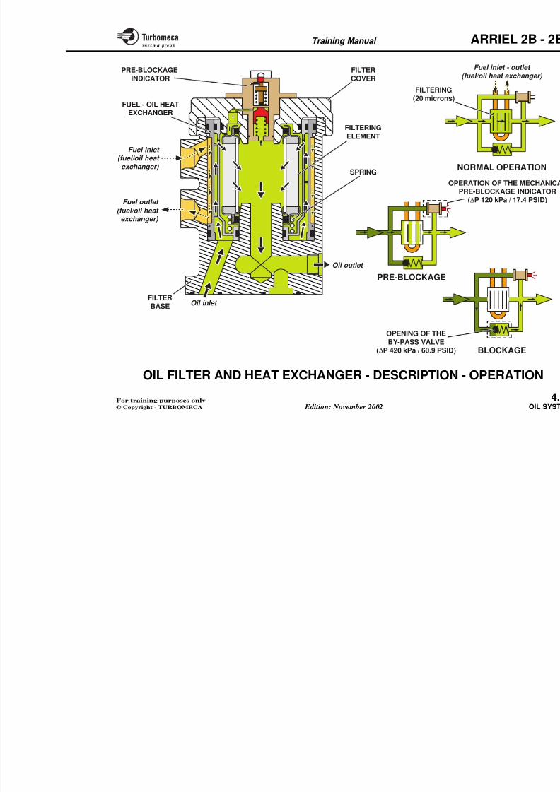
8/13/2019 Arriel_2B-2B1 11-02 En
http://slidepdf.com/reader/full/arriel2b-2b1-11-02-en 114/461
Fuel outlet (fuel/oil heat exchanger)
FILTERCOVER
OILFILTER
VISUAL PRE-BLOCKAGEINDICATOR
(re
(
Type :Glass fibre cartridge
Filtering ability :20 microns
Mechanicalpre-blockage indicator
setting :∆P 120 kPa (17.4 PSID)
By-pass valve setting :
Fuel inlet (fuel/oil heaexchanger)
From
oil tank
OILFILTER
Training Manual ARR
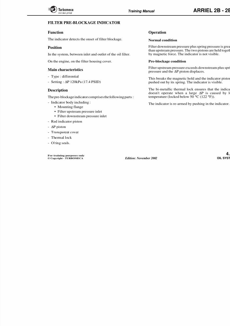
8/13/2019 Arriel_2B-2B1 11-02 En
http://slidepdf.com/reader/full/arriel2b-2b1-11-02-en 115/461
OIL FILTER AND HEAT EXCHANGER -
DESCRIPTION - OPERATION
Description
The main components of the filtering unit are the following :
- Filter base
- Filter cover (screwed onto the filter base)
- Fuel-oil heat exchanger fitted with walls which permitfuel flow around the oil filter casing
- Fibre glass cartridge (filtering element)
- By-pass valve (fitted inside the filter housing)
- Pre-blockage indicator
- Spring.
The filter base incorporates :
- Mounting points for the following :• Low oil pressure switch
• Oil pressure transmitter
• Oil outlet unions (compressor bearing lubrication
and rear bearing lubrication)• Fuel inlet and outlet unions.
Operation
Filtering (normal condition)
The oil supplied by the pressure pumfilter from outside to inside. The filtethe engine for lubrication.
The oil is also used to heat the fu
exchanger as the fuel flows around t
Pre-blockage
If the filter begins to become blocked thacross the filter increases. At a given 17.4 PSID) a red mechanical indicatcontinues to flow through the filter.
Blockage
If the pressure difference exceeds 4the by-pass valve opens and unfiltesystem.
Training Manual ARR
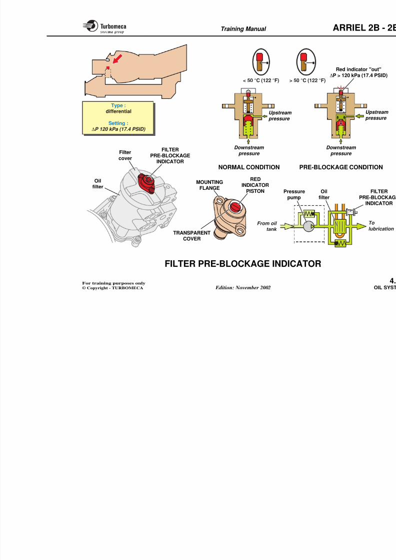
8/13/2019 Arriel_2B-2B1 11-02 En
http://slidepdf.com/reader/full/arriel2b-2b1-11-02-en 116/461
FILTERCOVER
PRE-BLOCKAGEINDICATOR
NORMAL
FILTERING(20 microns)
OPERATION OPRE-BLOC
(∆P 120 k
FILTERINGELEMENT
FUEL - OIL HEATEXCHANGER
Oil inlet
Fuel outlet
(fuel/oil heat exchanger)
Fuel inlet
(fuel/oil heat exchanger)
Fuel in
(fuel/oil he
Oil outlet
FILTERBASE
SPRING
PRE-BLOCKAGE
OPENING OF THE
Training Manual ARR
8/13/2019 Arriel_2B-2B1 11-02 En
http://slidepdf.com/reader/full/arriel2b-2b1-11-02-en 117/461
FILTER PRE-BLOCKAGE INDICATOR
Function
The indicator detects the onset of filter blockage.
Position
In the system, between inlet and outlet of the oil filter.
On the engine, on the filter housing cover.
Main characteristics
- Type : differential
- Setting : ∆P 120kPa (17.4 PSID)
Description
The pre-blockage indicator comprises the following parts :- Indicator body including :
• Mounting flange
• Filter upstream pressure inlet
• Filter downstream pressure inlet
- Red indicator piston
- ∆
P piston- Transparent cover
Th l l k
Operation
Normal condition
Filter downstream pressure plus sprinthan upstream pressure. The two pistby magnetic force. The indicator is n
Pre-blockage condition
Filter upstream pressure exceeds dowpressure and the ∆P piston displaces
This breaks the magnetic hold and thpushed out by its spring. The indicat
The bi-metallic thermal lock ensuredoesn't operate when a large ∆P
temperature (locked below 50 °C (12
The indicator is re-armed by pushing
Training Manual ARR
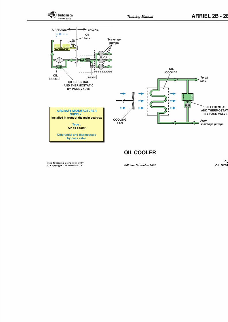
8/13/2019 Arriel_2B-2B1 11-02 En
http://slidepdf.com/reader/full/arriel2b-2b1-11-02-en 118/461
Type :differential
Setting :∆P 120 kPa (17.4 PSID)
< 50 °C (122 °F) > 50 °C (122 °F)
Downstream pressure
Downstreapressure
Upstream pressure
NORMAL CONDITION
Red in∆P > 120
PRE-BLOCKAGE C
Oilfilter
TRANSPARENT
FILTERPRE-BLOCKAGE
INDICATOR
REDINDICATOR
PISTON
Filtercover
MOUNTINGFLANGE
From oil tank
Oilfilter
Pressurepump
8/13/2019 Arriel_2B-2B1 11-02 En
http://slidepdf.com/reader/full/arriel2b-2b1-11-02-en 119/461
Training Manual ARR
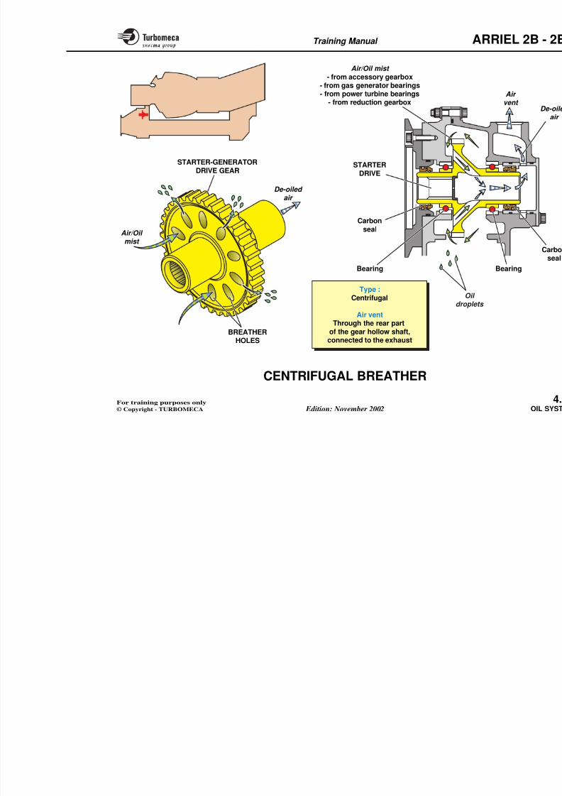
8/13/2019 Arriel_2B-2B1 11-02 En
http://slidepdf.com/reader/full/arriel2b-2b1-11-02-en 120/461
Indication
AIRCRAFT MANUFACTURER
SUPPLY :Installed in front of the main gearbox
Type :
Air-oil cooler
Differential and thermostatic
T
ta
Fs
COOLING
FAN
A
OIL
COOLEROIL
COOLER
Oiltank Scavenge
pumps
DIFFERENTIALAND THERMOSTATIC
BY-PASS VALVE
ENGINEAIRFRAME
Training Manual ARR
8/13/2019 Arriel_2B-2B1 11-02 En
http://slidepdf.com/reader/full/arriel2b-2b1-11-02-en 121/461
CENTRIFUGAL BREATHER
Function
The centrifugal breather separates the oil from the air/oilmist created by the oil system.
Position
- In the system : before the general vent line of the system.
- On the engine : it is formed by the starter/generator drivegear in the accessory gearbox.
Main characteristics
- Type : centrifugal
- Air vent : through the rear part of the gear hollow shaft,
connected to the exhaust.
Description
The centrifugal breather is formed by the starter-generatordrive gear. This gear is formed in one piece with a hollowshaft and has holes which provide a passage between thegearbox and the air vent.
The gear is supported by two ball bearings and has amagnetic carbon seal at each end.
Operation
The centrifugal breather is driven by tof the accessory drive.
When the engine is running the air/oithe breather :
- Centrifugal force throws the oil d
gearbox where they fall to the bott
- The de-oiled air passes out througearbox passage, into an external pinto the exhaust.
Training Manual ARR
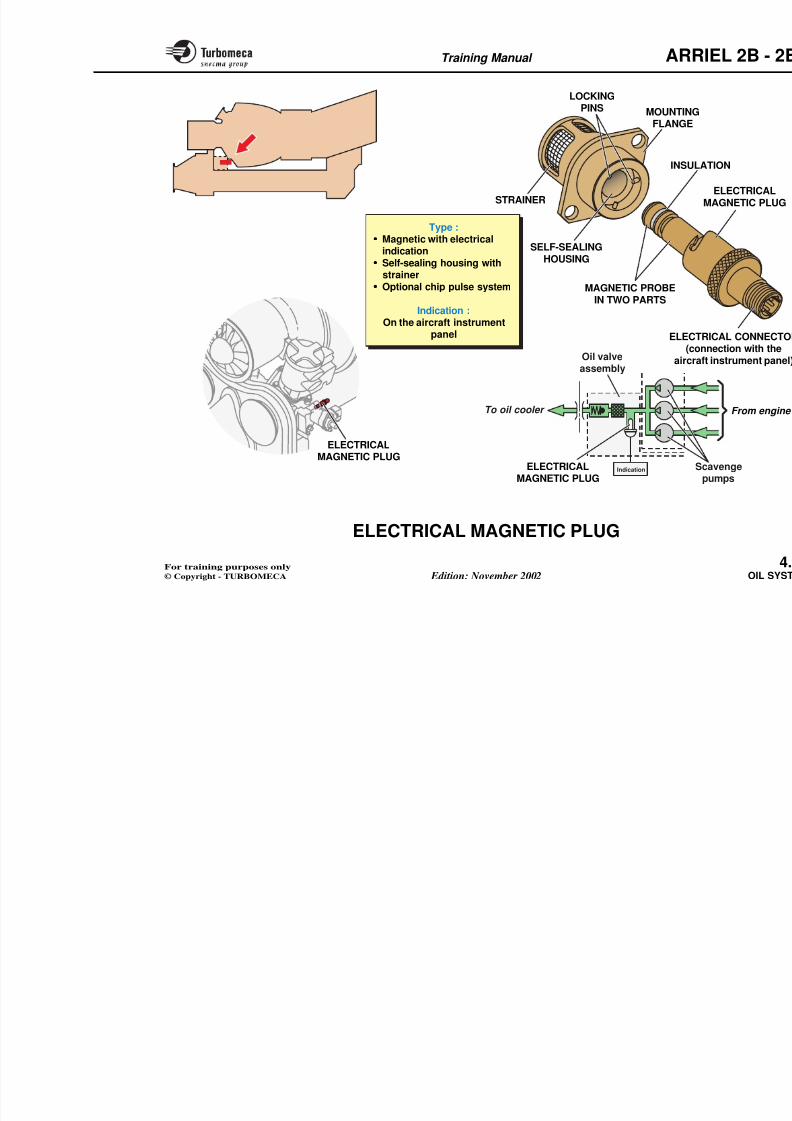
8/13/2019 Arriel_2B-2B1 11-02 En
http://slidepdf.com/reader/full/arriel2b-2b1-11-02-en 122/461
B
Oil droplets
Air/Oil mist
- from accessory gearbox
- from gas generator bearings- from power turbine bearings
- from reduction gearbox
STARTERDRIVE
Carbonseal
Bearing
STARTER-GENERATORDRIVE GEAR
Air/Oil mist
De-oiled air
BREATHER
Type :Centrifugal
Air ventThrough the rear part
of the gear hollow shaft,
Training Manual ARR
8/13/2019 Arriel_2B-2B1 11-02 En
http://slidepdf.com/reader/full/arriel2b-2b1-11-02-en 123/461
ELECTRICAL MAGNETIC PLUG
Function
The electrical magnetic plug attracts magnetic particles inthe oil system and provides a cockpit indication.
Position
- In the system : downstream of the scavenge pumps
- On the engine : mounted on the oil valve assembly.
Main characteristics
- Type :
• Magnetic with electrical indication
• Self-sealing housing with strainer
• Optional chip pulse system.
- Indication : light on the aircraft instrument panel.
Description
The electrical magnetic plug comprises a magnetic probewhich has two parts which are electrically insulated from
one another and have a small gap between them.
The plug is connected, via the engine electrical harness, to
The plug is fitted into a housing whic
self-sealing valve and a mounting flaA bayonet type locking pin system enthe electrical magnetic plug.
The housing is bolted onto the oil vathe scavenge oil can flow across the
Operation
The magnetic probe attracts magnetithe oil.
If it attracts sufficient particles to formgap, this will complete the electricaltwo magnetic parts and thus providaircraft instrument panel.
Note 1 : The oil system also has two plugs, one located on the accessory gearbox and onthe reduction gearbox.
Note 2 : An optional chip pulse sysby the aircraft manufactudebris to be burnt off.
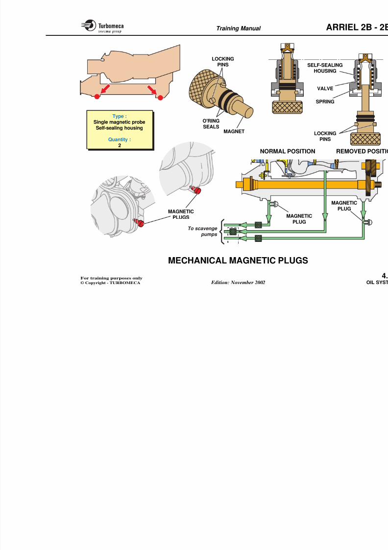
8/13/2019 Arriel_2B-2B1 11-02 En
http://slidepdf.com/reader/full/arriel2b-2b1-11-02-en 124/461
Training Manual ARR
8/13/2019 Arriel_2B-2B1 11-02 En
http://slidepdf.com/reader/full/arriel2b-2b1-11-02-en 125/461
MECHANICAL MAGNETIC PLUGS
Function
The magnetic plugs retain magnetic particles which maybe in the oil.
Position
In the system :
- One on the reduction gear scavenge return
- One on the accessory gearbox scavenge return.
On the engine :
- One at the bottom of the reduction gearbox
- One at the bottom of the accessory gearbox.
Main characteristics
- Type : single magnetic probe. Self-sealing housing
- Quantity : 2.
Description
The magnetic plug includes : a maglocating pins.
The magnetic plug is installed in a (valve, spring).
Training Manual ARR
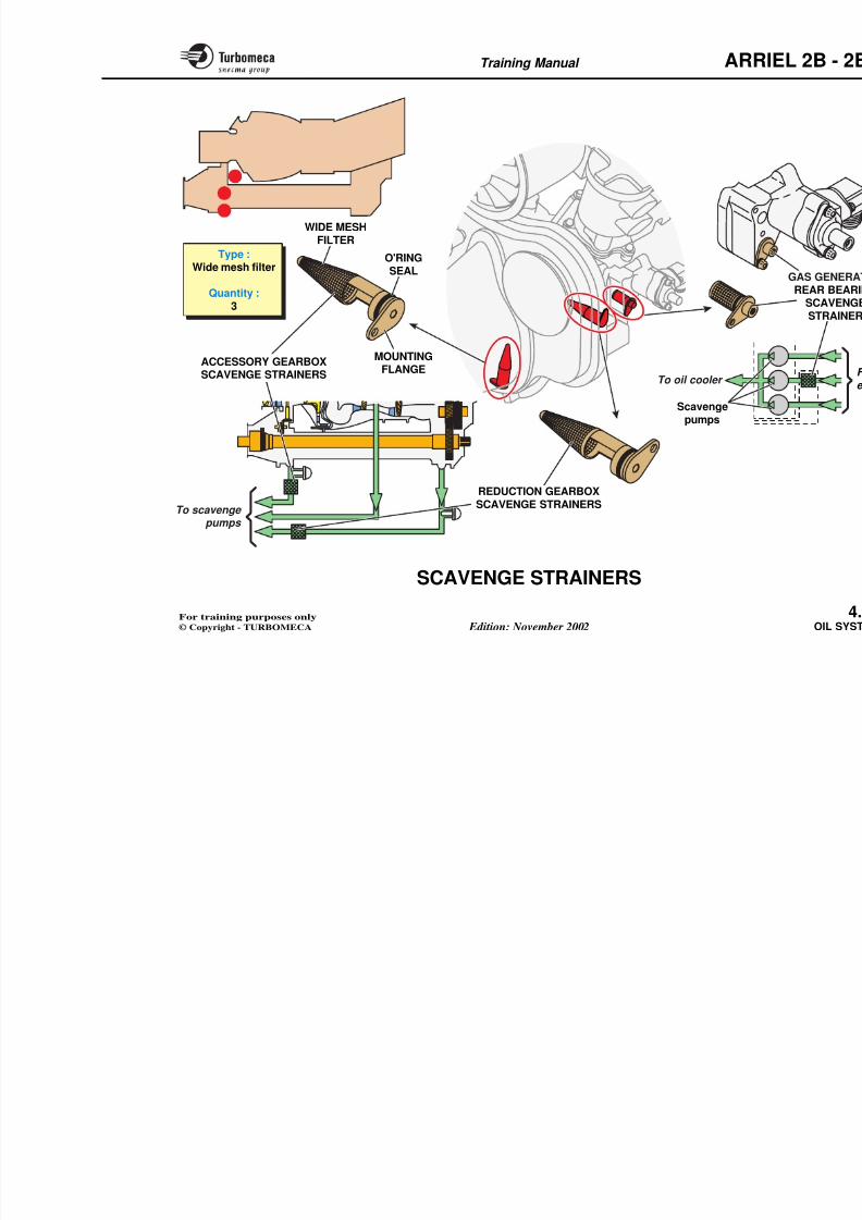
8/13/2019 Arriel_2B-2B1 11-02 En
http://slidepdf.com/reader/full/arriel2b-2b1-11-02-en 126/461
LOCKINGPINS
RENORMAL POSITION
VALVE
SELF-SEALINGHOUSING
SPRING
O'RINGSEALS
MAGNET LOCKINGPINS
To scavenge
MAGNETICPLUG
MAGNPL
MAGNETIC
PLUGS
Type :Single magnetic probeSelf-sealing housing
Quantity :2
Training Manual ARR
SCAVENGE STRAINERS
8/13/2019 Arriel_2B-2B1 11-02 En
http://slidepdf.com/reader/full/arriel2b-2b1-11-02-en 127/461
SCAVENGE STRAINERS
Function
The strainers protect the scavenge pumps against largeparticles which might be in the oil.
Position
- In the system :• One strainer is fitted in each scavenge line upstream
of the scavenge pump
• One strainer is located downstream of the scavengepumps
- On the engine :• Two different strainers are located on the accessory
gearbox casing:
- one to the reduction gearbox- one to the accessory gearbox scavenge
• One strainer is located on the oil valve assembly (gasgenerator rear bearing scavenge).
Main characteristics
- Type : wide mesh filter- Quantity : 3.
Description
Each strainer includes the following mesh filter, a mounting flange and a
Operation
A strainer is a wide mesh filter whiparticles which may be present in the the scavenge pumps.
Note : The electrical magnetic plugvalve assembly, is fitted with
Training Manual ARR
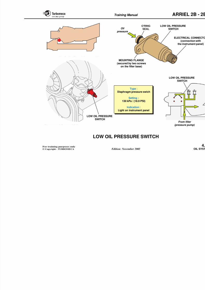
8/13/2019 Arriel_2B-2B1 11-02 En
http://slidepdf.com/reader/full/arriel2b-2b1-11-02-en 128/461
Type :Wide mesh filter
Quantity :3
WIDE MESHFILTER
O'RINGSEAL
MOUNTING
FLANGE
To scavenge
To oil cooler
Scavengepumps
ACCESSORY GEARBOXSCAVENGE STRAINERS
REDUCTION GEARBOXSCAVENGE STRAINERS
Training Manual ARR
LOW OIL PRESSURE SWITCH
8/13/2019 Arriel_2B-2B1 11-02 En
http://slidepdf.com/reader/full/arriel2b-2b1-11-02-en 129/461
LOW OIL PRESSURE SWITCH
Function
The low oil pressure switch provides cockpit indication of low oil pressure.
Position
- In the system : downstream of the filter
- On the engine : mounted on the filter base.
Main characteristics
- Type : diaphragm pressure switch
- Setting : 130 kPa (18.9 PSI)
- Indication : light on instrument panel.
Description
The pressure switch comprises the following components :a mounting flange and an electrical connector (connectionwith the instrument panel).
The pressure switch is secured by means of two screwsonto the filter base.
Operation
The pressure switch microswitch is engine operation.
If the oil pressure reduces to less thanthe diaphragm moves down. This ccontact to close, completing the cipressure warning light.
Training Manual ARR
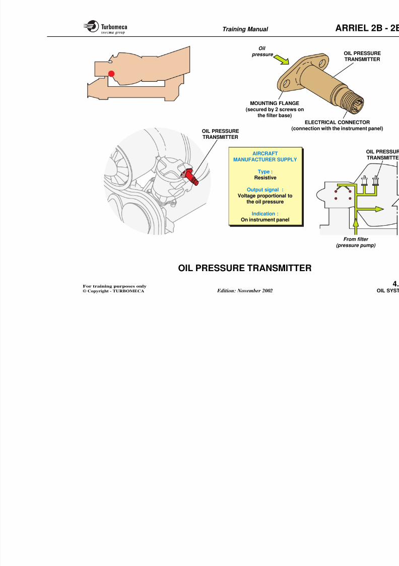
8/13/2019 Arriel_2B-2B1 11-02 En
http://slidepdf.com/reader/full/arriel2b-2b1-11-02-en 130/461
Fro
LOW OIL PSW
LOW OIL PRESSURESWITCH
Type :Diaphragm pressure swich
Setting :130 kPa / (18.9 PSI)
Indication :Light on instrument panel
Oil
pressure
LOW OIL PRESSUSWITCH
O'RINGSEAL
MOUNTING FLANGE(secured by two screws
on the filter base)
ELECT(
the
Training Manual ARR
OIL PRESSURE TRANSMITTER
8/13/2019 Arriel_2B-2B1 11-02 En
http://slidepdf.com/reader/full/arriel2b-2b1-11-02-en 131/461
OIL PRESSURE TRANSMITTER
Function
The transmitter provides a signal of oil pressure.
Position
- In the system : in the supply system, downstream of thefilter after the restrictor.
- On the engine : mounted on the filter base.
Main characteristics
- Supplied by the aircraft manufacturer
- Type : resistive
- Output signal : voltage proportional to the oil pressure
- Indication : on instrument panel.
Description
The transmitter includes :
- A mounting flange (mounting on t
- An electrical connector (connectiopanel).
Operation
The oil pressure transmitter incorporateprinted on a flexible support.
The deformation of the support produproportional to the oil pressure for a co
Training Manual ARR
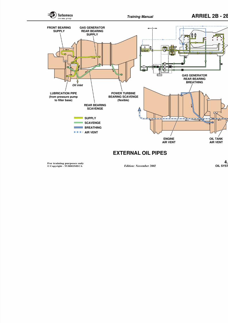
8/13/2019 Arriel_2B-2B1 11-02 En
http://slidepdf.com/reader/full/arriel2b-2b1-11-02-en 132/461
ELECTRICAL CONN(connection with the instru
MOUNTING FLANGE(secured by 2 screws on
the filter base)
OIL TRA
Oil
pressure
AIRCRAFTMANUFACTURER SUPPLY
Type :Resistive
Output signal :Voltage proportional to
the oil pressure
Indication :On instrument panel
OIL PRESSURETRANSMITTER
Training Manual ARR
EXTERNAL OIL PIPES
8/13/2019 Arriel_2B-2B1 11-02 En
http://slidepdf.com/reader/full/arriel2b-2b1-11-02-en 133/461
EXTERNAL OIL PIPES
This description deals with the external pipes of the oilsystem.
Function
The oil pipes ensure the oil circulation between the oilsystem components and the lubricated parts of the engine(bearings).
Main characteristics
- Type of pipelines : rigid (one flexible)
- Type of union : flanged union.
Description
Lubrication
- Oil inlet (from oil tank to pressure pump ; aircraftmanufacturer supply)
- From pressure pump to filter base
- Supply of the gas generator front bearings
- Supply of the gas generator rear bearing.
Scavenge
- Scavenge of the gas generator rear
- Scavenge of the power turbine beturbine to reduction gearbox ; flex
Breathing
- Gas generator rear bearing (extern
Air vent
- External pipe from centrifugal brepipe.
Training Manual ARR
8/13/2019 Arriel_2B-2B1 11-02 En
http://slidepdf.com/reader/full/arriel2b-2b1-11-02-en 134/461
LUBRICATION PIPE
(from pressure pumpto filter base)
POWER TURBINE
BEARING SCAVENGE(flexible)
GAS GENERATORREAR BEARING
SUPPLY
REAR BEARINGSCAVENGE
Oil inlet
GAS GENERATREAR BEARIN
BREATHING
FRONT BEARINGSUPPLY
SUPPLY
SCAVENGE
BREATHINGAIR VENT
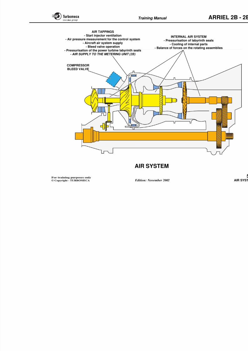
8/13/2019 Arriel_2B-2B1 11-02 En
http://slidepdf.com/reader/full/arriel2b-2b1-11-02-en 135/461
Training Manual ARR
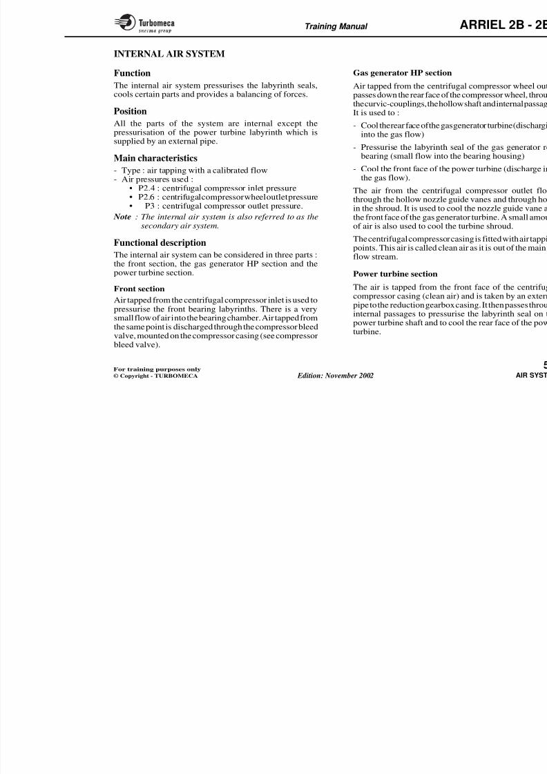
8/13/2019 Arriel_2B-2B1 11-02 En
http://slidepdf.com/reader/full/arriel2b-2b1-11-02-en 136/461
5-AIR SYSTEM
- Air system (75-00-00)............................................. 5.2
- Internal air system (75-00-00)............................... 5.4
- Air tappings (75-00-00).......................................... 5.6
- Compressor bleed valve (75-31-00) ...................... 5.8
- P3 pressure transmitter (75-41-00)....................... 5.12
- Air tapping unions (75-00-00) ............................... 5.14
- External air pipes (75-29-00) ................................ 5.16
Training Manual ARR
AIR SYSTEM
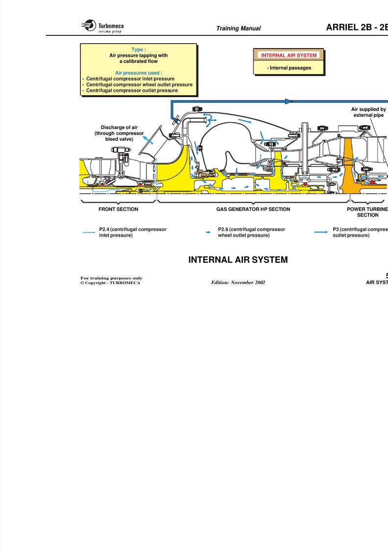
8/13/2019 Arriel_2B-2B1 11-02 En
http://slidepdf.com/reader/full/arriel2b-2b1-11-02-en 137/461
AIR SYSTEM
Function
The engine air system includes :
- An internal air system which ensures :
• The pressurisation of the labyrinth seals
• The cooling of the engine internal parts
• The balance of forces on the rotating assemblies
- Air tappings which ensure :• The air pressure measurement for the control system
• The start injector ventilation
• The aircraft air system supply
• 2B : The air supply to the pump and metering unit assembly (metering unit)
• The air for the bleed valve operation
• The air for the pressurisation of the power turbinelabyrinth seals.
- The compressor bleed valve.
Note : Refer to the various systems for the location, thecharacteristics, the description and operation.
Training Manual ARR
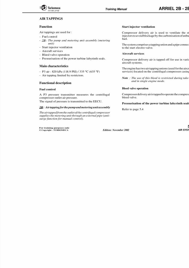
8/13/2019 Arriel_2B-2B1 11-02 En
http://slidepdf.com/reader/full/arriel2b-2b1-11-02-en 138/461
INTERNAL AIR SYSTEM- Pressurisation of labyrinth seals
- Cooling of internal parts- Balance of forces on the rotating assemblie
AIR TAPPINGS
- Start injector ventilation
- Air pressure measurement for the control system- Aircraft air system supply
- Bleed valve operation- Pressurisation of the power turbine labyrinth seals
- AIR SUPPLY TO THE METERING UNIT (2B)
COMPRESSORBLEED VALVE
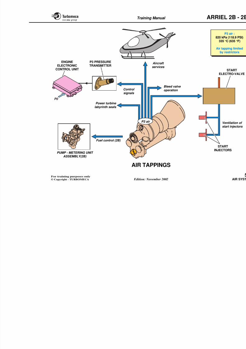
8/13/2019 Arriel_2B-2B1 11-02 En
http://slidepdf.com/reader/full/arriel2b-2b1-11-02-en 139/461
Training Manual ARR
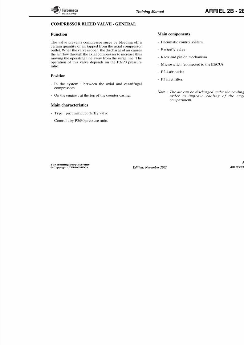
8/13/2019 Arriel_2B-2B1 11-02 En
http://slidepdf.com/reader/full/arriel2b-2b1-11-02-en 140/461
INTERNAL AIR SYSTEM
FRONT SECTION GAS GENERATOR HP SECTION
Discharge of air(through compressor
bleed valve)
- Internal passages
P2.4 (centrifugal compressor P2.6 (centrifugal compressor P3 (c
Type :Air pressure tapping with
a calibrated flow
Air pressures used :- Centrifugal compressor inlet pressure- Centrifugal compressor wheel outlet pressure- Centrifugal compressor outlet pressure
Training Manual ARR
AIR TAPPINGS
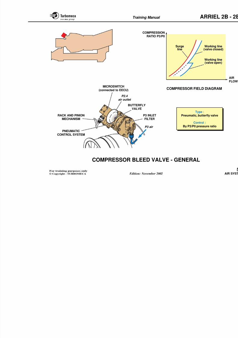
8/13/2019 Arriel_2B-2B1 11-02 En
http://slidepdf.com/reader/full/arriel2b-2b1-11-02-en 141/461
AIR TAPPINGS
Function
Air tappings are used for :
- Fuel control
- 2B : The pump and metering unit assembly (meteringunit)
- Start injector ventilation
- Aircraft services
- Bleed valve operation- Pressurisation of the power turbine labyrinth seals.
Main characteristics
- P3 air : 820 kPa (118.9 PSI) / 335 °C (635 °F)
- Air tapping limited by restrictors.
Functional description
Fuel control
A P3 pressure transmitter measures the centrifugalcompressor outlet air pressure.
The signal of pressure is transmitted to the EECU.
2B: Air tapping for the pump and metering unit assembly
Theair tappedfromtheoutletof thecentrifugalcompressor
Start injector ventilation
Compressor delivery air is used toinjectors to avoid blockage by the carbfuel.
The system comprises a tapping unionto the start electro-valve.
Aircraft services
Compressor delivery air is tapped oaircraft systems.
The engine has two air tapping unionsservices) located on the centrifugal c
Note : The use of this bleed is restr
and in single engine mode.
Bleed valve operation
Compressor delivery air is tapped to opbleed valve.
Pressurisation of the power turbin
Refer to page 5.4
Training Manual ARR
8/13/2019 Arriel_2B-2B1 11-02 En
http://slidepdf.com/reader/full/arriel2b-2b1-11-02-en 142/461
P0
82
A
ENGINEELECTRONIC
CONTROL UNIT
P3 PRESSURETRANSMITTER
Aircraft services
Bleed valve operation Control
signals
Power turbine
labyrinth seals
Fuel control (2B)
P3 air
Training Manual ARR
COMPRESSOR BLEED VALVE - GENERAL
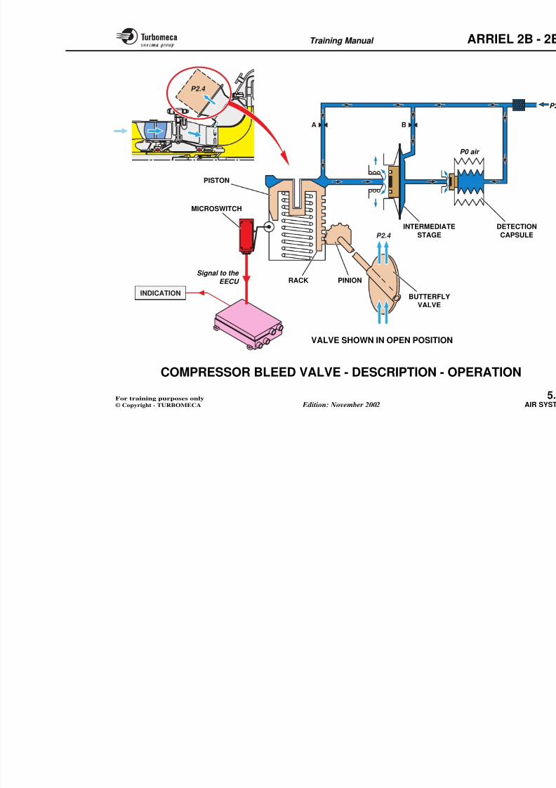
8/13/2019 Arriel_2B-2B1 11-02 En
http://slidepdf.com/reader/full/arriel2b-2b1-11-02-en 143/461
Function
The valve prevents compressor surge by bleeding off acertain quantity of air tapped from the axial compressoroutlet. When the valve is open, the discharge of air causesthe air flow through the axial compressor to increase thusmoving the operating line away from the surge line. Theoperation of this valve depends on the P3/P0 pressureratio.
Position
- In the system : between the axial and centrifugalcompressors
- On the engine : at the top of the counter casing.
Main characteristics
- Type : pneumatic, butterfly valve
- Control : by P3/P0 pressure ratio.
Main components
- Pneumatic control system
- Butterfly valve
- Rack and pinion mechanism
- Microswitch (connected to the EE
- P2.4 air outlet
- P3 inlet filter.
Note : The air can be discharged uorder to improve coolincompartment.
Training Manual ARR
8/13/2019 Arriel_2B-2B1 11-02 En
http://slidepdf.com/reader/full/arriel2b-2b1-11-02-en 144/461
Type :Pneumatic, butterfly
Control :By P3/P0 pressure r
MICROSWITCH(connected to EECU)
RACK AND PINIONMECHANISM
BUTTERFLYVALVE
P3 INLETFILTER
P2.4 air outlet
P3 air
PNEUMATIC
CONTROL SYSTEM
COMPRESSION
RATIO P3/P0
COMPRESSOR FIELD DIA
Surgeline
Work(valv
Work(valv
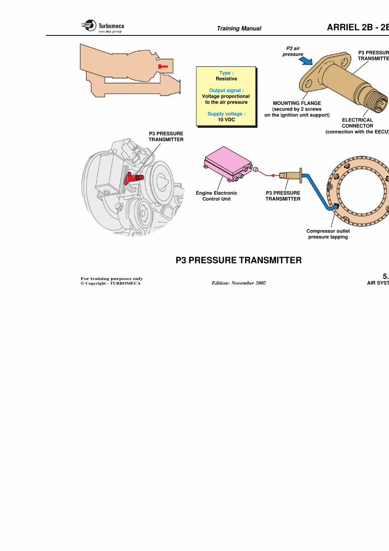
8/13/2019 Arriel_2B-2B1 11-02 En
http://slidepdf.com/reader/full/arriel2b-2b1-11-02-en 145/461
Training Manual ARR
8/13/2019 Arriel_2B-2B1 11-02 En
http://slidepdf.com/reader/full/arriel2b-2b1-11-02-en 146/461
A B
P2.4
P2.4
RACK
INDICATION
MICROSWITCH
P0 air
INTERMEDIATE
STAGE
Signal to the
EECU
BUTTERFLYVALVE
PINION
PISTON
Training Manual ARR
P3 PRESSURE TRANSMITTER
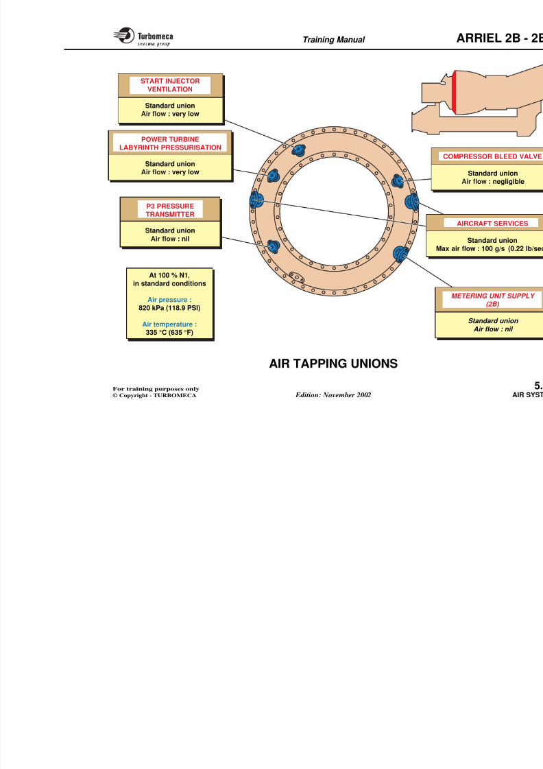
8/13/2019 Arriel_2B-2B1 11-02 En
http://slidepdf.com/reader/full/arriel2b-2b1-11-02-en 147/461
Function
The P3 pressure transmitter senses the compressor outletair pressure and supplies a signal to the EECU.
Position
In the system : connected to the EECU.
On the engine : on the ignition unit support.
Main characteristics
- Type : resistive
- Output signal : voltage proportional to the air pressure
- Supply voltage : 10 VDC.
Description
The P3 pressure transmitter system comprises the P3tapping, an air pipe and the pressure transmitter.
The transmitter is secured on the ignition unit support by
2 screws.
The electrical connector provides the connection with the
Operation
The transmitter produces an electricalto the P3 air pressure.
The pressure signal is used by the EEC(fuel flow limit, surge control).
Training Manual ARR
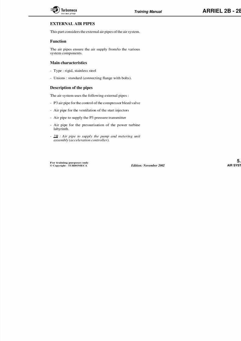
8/13/2019 Arriel_2B-2B1 11-02 En
http://slidepdf.com/reader/full/arriel2b-2b1-11-02-en 148/461
Type :Resistive
Output signal :Voltage proportional
to the air pressure
Supply voltage :10 VDC
P3 PRESSURE
TRANSMITTER
Compressor out
Engine Electronic
Control Unit
P3 air pressure
MOUNTING FLANGE(secured by 2 screws
on the ignition unit support)E
C(connecP3 PRESSURE
TRANSMITTER
Training Manual ARR
AIR TAPPING UNIONS
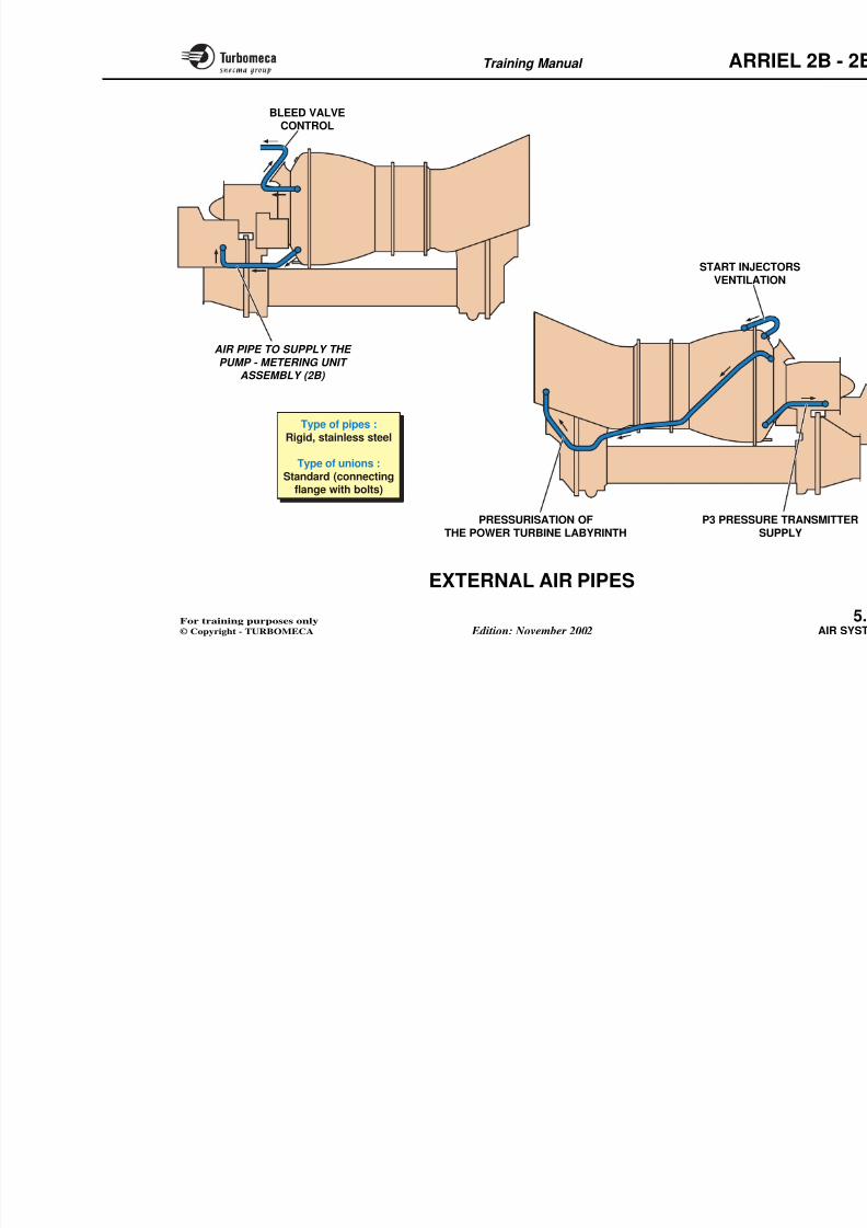
8/13/2019 Arriel_2B-2B1 11-02 En
http://slidepdf.com/reader/full/arriel2b-2b1-11-02-en 149/461
Function
The air tapping unions allow air to be tapped from thecentrifugal compressor outlet.
Position
They are located on the centrifugal compressor casingfront face. The air in this zone is considered clean air as it
is out of the main air stream and thus contains very littledebris.
Main characteristics
At 100 % N1, in standard conditions :
- Air pressure : 820 kPa (118.9 PSI)
- Air temperature : 335 °C (635 °F)
Functional description
Start injector ventilation
Standard union.
Air flow : very low.
Power turbine labyrinth pressurisation
P3 pressure transmitter
Standard union.
Air flow : nil.
Aircraft services
Standard union.
Max air flow : 100 g/s (0.22 lb/sec.)
Compressor bleed valve
Standard union.
Air flow : negligible.
2B: Metering unit supply
Standard union.
Air flow : nil.
Training Manual ARR
8/13/2019 Arriel_2B-2B1 11-02 En
http://slidepdf.com/reader/full/arriel2b-2b1-11-02-en 150/461
At 100 % N1,
in standard conditions
Air pressure :
820 kPa (118.9 PSI)
Ai t t
START INJECTOR
VENTILATION
Standard unionAir flow : very low
POWER TURBINELABYRINTH PRESSURISATION
Standard unionAir flow : very low
AIRCRA
StanMax air flow :
P3 PRESSURE
TRANSMITTER
Standard unionAir flow : nil
COMPRESS
StanAir flo
METERIN
Stan
Training Manual ARR
EXTERNAL AIR PIPES
8/13/2019 Arriel_2B-2B1 11-02 En
http://slidepdf.com/reader/full/arriel2b-2b1-11-02-en 151/461
This part considers the external air pipes of the air system.
Function
The air pipes ensure the air supply from/to the varioussystem components.
Main characteristics
- Type : rigid, stainless steel
- Unions : standard (connecting flange with bolts).
Description of the pipes
The air system uses the following external pipes :
- P3 air pipe for the control of the compressor bleed valve
- Air pipe for the ventilation of the start injectors
- Air pipe to supply the P3 pressure transmitter
- Air pipe for the pressurisation of the power turbinelabyrinth.
- 2B : Air pipe to supply the pump and metering unit assembly (acceleration controller).
Training Manual ARR
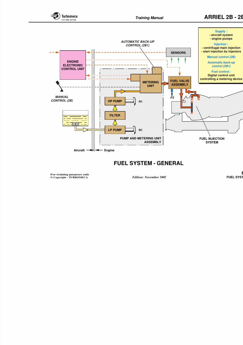
8/13/2019 Arriel_2B-2B1 11-02 En
http://slidepdf.com/reader/full/arriel2b-2b1-11-02-en 152/461
BLEED VALVECONTROL
START INJECVENTILAT
Type of pipes :Rigid, stainless steel
Type of unions :Standard (connecting
flange with bolts)
AIR PIPE TO SUPPLY THE
PUMP - METERING UNIT
ASSEMBLY (2B)
8/13/2019 Arriel_2B-2B1 11-02 En
http://slidepdf.com/reader/full/arriel2b-2b1-11-02-en 153/461
Training Manual ARR
6 FUEL SYSTEM
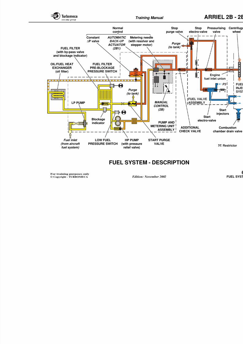
8/13/2019 Arriel_2B-2B1 11-02 En
http://slidepdf.com/reader/full/arriel2b-2b1-11-02-en 154/461
6-FUEL SYSTEM- Fuel system (73-00-00) ........................................... 6.2
- Pump and metering unit assembly (73-23-00)..... 6.16
• Fuel pumps (73-23-00) .................................. 6.18
• Start purge valve (73-23-00) ......................... 6.22
• Metering unit (73-23-00) ............................... 6.24
- Fuel filter (73-23-11) .............................................. 6.42
- Fuel filter pre-blockage pressure switch (73-23-32) 6.48
- Fuel filter blockage indicator (73-23-31) ............. 6.50
- Low fuel pressure switch (73-23-33)..................... 6.52- Fuel valve assembly (73-14-00) ............................. 6.54
- Main injection system (72-00-43) ......................... 6.58
- Engine fuel inlet union (72-43-00) ........................ 6.60
- Start injectors (72-43-00) ...................................... 6.62Combustion chamber drain valve (71 71 00) 6 66
Training Manual ARR
FUEL SYSTEM - GENERAL
8/13/2019 Arriel_2B-2B1 11-02 En
http://slidepdf.com/reader/full/arriel2b-2b1-11-02-en 155/461
Main components
- Pump and metering unit assembly
• LP pump
• Filter
• HP pump
• Metering unit.
- Fuel valve assembly
- Injection system.
Function
The fuel system ensures fuel supply, distribution, control,metering and injection.
Position
All the system components are mounted on the engineexcept the EECU.
Main characteristics
- Supply by the aircraft system and the engine pumps
- Centrifugal main injection and start injection by injectors
- 2B : Manual control
- 2B1: Automatic back-up control
- Fuel control : digital control unit controlling a meteringdevice.
Training Manual ARR
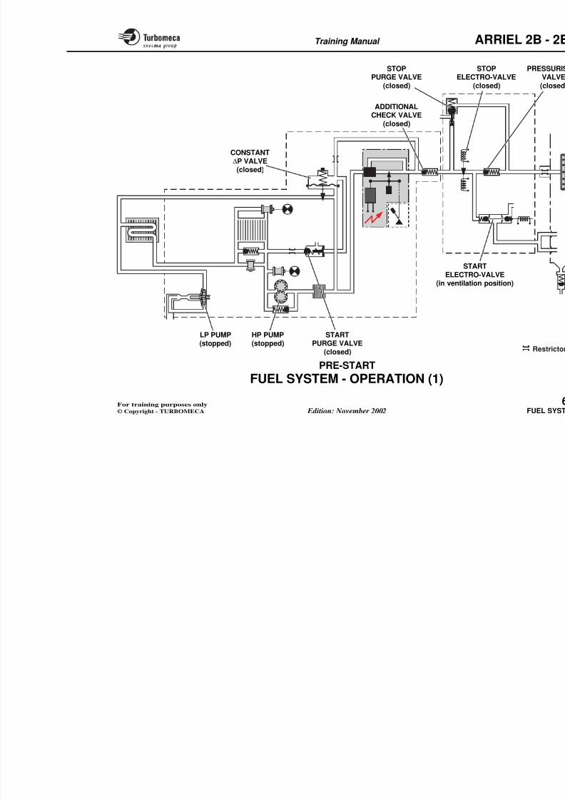
8/13/2019 Arriel_2B-2B1 11-02 En
http://slidepdf.com/reader/full/arriel2b-2b1-11-02-en 156/461
P3
N1
N1
FUEL VALVE
ASSEMBLY
PUMP AND METERING UNITASSEMBLY
SENSORS
HP PUMP
FILTER
LP PUMP
MANUAL
CONTROL (2B)
METERINGUNIT
FUEL INJESYSTE
AUTOMATIC BACK-UP CONTROL (2B1)
ENGINE
ELECTRONICCONTROL UNIT
- air
- en
I- centrifu- start inje
Manu
Automco
FuDigita
controlling
Training Manual ARR
FUEL SYSTEM - DESCRIPTION Metering unit

8/13/2019 Arriel_2B-2B1 11-02 En
http://slidepdf.com/reader/full/arriel2b-2b1-11-02-en 157/461
This part shows the main components of the fuel system.
Low pressure pump (LP)
Centrifugal type pump which gives an initial pressure rise.
Oil/Fuel heat exchanger (oil filter)
Filter
Fitted between the LP and HP pumps, this filter has ablockage indicator and a by-pass valve.
Start purge valve
To eliminate air from the system before start.
Fuel filter pre-blockage pressure switch
Provides a cockpit indication of the onset of the filterblockage.
Low fuel pressure switch
Sensing the filter outlet pressure, it gives a cockpit indicationof system low pressure.
High pressure pump (HP)
- Normal control (stepper motor, resoconstant ∆P valve)
- 2B : Manual control : twist grip - 2B1 : Automatic back-up control
actuator (the actuator is supplmanufacturer).
Additional check valve
The valve permits the correct operatiovalve in low fuel flow conditions
starting).
Fuel valve assembly
- Start electro-valve
- Stop electro-valve
- Pressurising valve
- Stop purge valve.
Fuel injection system
- Start injectors (2)
- Main injection (centrifugal wheel)
- Engine fuel inlet union
- Combustion chamber drain valve.
Note : A fuel flowmeter, suppli
manufacturer, can be fitted bunit and the fuel valve assem
Training Manual ARR
PressStopNormal Stop
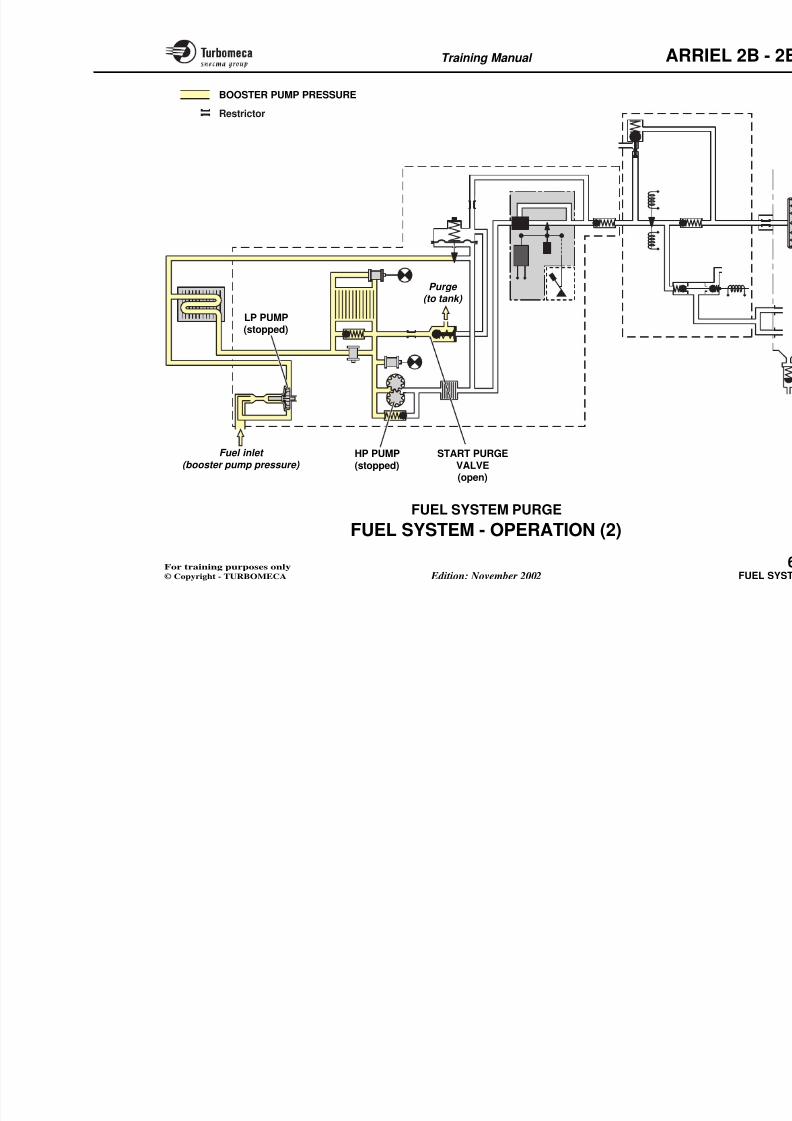
8/13/2019 Arriel_2B-2B1 11-02 En
http://slidepdf.com/reader/full/arriel2b-2b1-11-02-en 158/461
Constant∆P valve AUTOMATIC BACK-UP
ACTUATOR (2B1)
Metering needle(with resolver andstepper motor)
ADDITIONALCHECK VALVE
Pressva
Stoppurge valve
PUMP ANDMETERING UNIT
ASSEMBLY
MANUALCONTROL
(2B)
HP PUMP(with pressure
Fuel inlet
(from aircraft
Purge (to tank)
LOW FUELPRESSURE SWITCH
FUEL FILTER(with by-pass valve
and blockage indicator)
OIL/FUEL HEATEXCHANGER
(oil filter)
Blockageindicator
START PURGEVALVE
Normalcontrol
FUEL FILTERPRE-BLOCKAGE
PRESSURE SWITCH
LP PUMP
Startelectro-valve
Stopelectro-valve
Engfuel inle
c
Purge (to tank)
FUEL VALVEASSEMBLY
Training Manual ARR
FUEL SYSTEM - OPERATION (1)
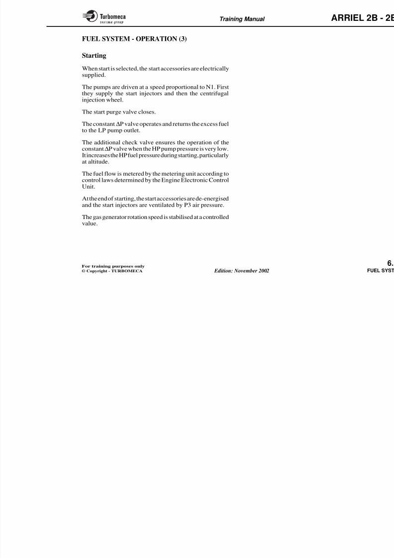
8/13/2019 Arriel_2B-2B1 11-02 En
http://slidepdf.com/reader/full/arriel2b-2b1-11-02-en 159/461
This part deals with the following operating phases : pre-start, purge, starting, normal running, back-up control and
shut-down.
Pre-start
- The LP and HP pumps do not operate and there is nopressure in the system
- The constant ∆P valve is closed
- The stop electro-valve is closed
- The pressurising valve is closed
- The additional check valve is closed
- The start purge valve is closed
- The stop purge valve is closed
- The start electro-valve is in the ventilation position (noelectrical supply).
2B : At power-up the metering valve is positioned to permit the engagement of the manual control should this be necessary.
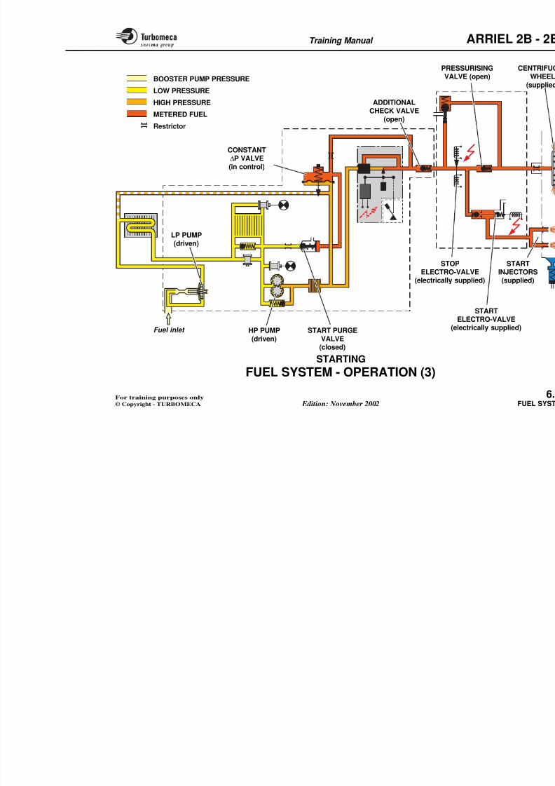
8/13/2019 Arriel_2B-2B1 11-02 En
http://slidepdf.com/reader/full/arriel2b-2b1-11-02-en 160/461
Training Manual ARR
FUEL SYSTEM - OPERATION (2)
8/13/2019 Arriel_2B-2B1 11-02 En
http://slidepdf.com/reader/full/arriel2b-2b1-11-02-en 161/461
Fuel system purge
Before starting, the booster pump is switched on. The lowpressure fuel flows through the LP pump and filter, and isreturned to the tank through the start purge valve.
This purge must be carried out before each start, for 15 to20 secs.
Training Manual ARR
BOOSTER PUMP PRESSURE
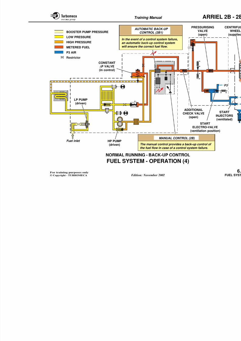
8/13/2019 Arriel_2B-2B1 11-02 En
http://slidepdf.com/reader/full/arriel2b-2b1-11-02-en 162/461
BOOSTER PUMP PRESSURE
START PURGEVALVE
HP PUMP(stopped)
Fuel inlet
(booster pump pressure)
Purge (to tank)
LP PUMP(stopped)
Restrictor
Training Manual ARR
FUEL SYSTEM - OPERATION (3)

8/13/2019 Arriel_2B-2B1 11-02 En
http://slidepdf.com/reader/full/arriel2b-2b1-11-02-en 163/461
Starting
When start is selected, the start accessories are electricallysupplied.
The pumps are driven at a speed proportional to N1. Firstthey supply the start injectors and then the centrifugalinjection wheel.
The start purge valve closes.
The constant ∆P valve operates and returns the excess fuelto the LP pump outlet.
The additional check valve ensures the operation of theconstant∆P valve when the HP pump pressure is very low.It increases the HP fuel pressure during starting, particularlyat altitude.
The fuel flow is metered by the metering unit according tocontrol laws determined by the Engine Electronic ControlUnit.
At the end of starting, the start accessories are de-energisedand the start injectors are ventilated by P3 air pressure.
The gas generator rotation speed is stabilised at a controlled
value.
Training Manual ARR
PRESSURISING
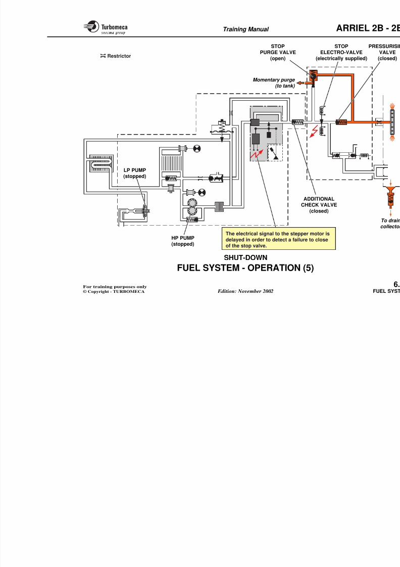
8/13/2019 Arriel_2B-2B1 11-02 En
http://slidepdf.com/reader/full/arriel2b-2b1-11-02-en 164/461
START PURGEHP PUMPFuel inlet
LP PUMP(driven)
BOOSTER PUMP PRESSURE
LOW PRESSURE
HIGH PRESSURE
METERED FUEL
CONSTANT∆P VALVE
(in control)
ADDITIONALCHECK VALVE
(open)
PRESSURISINGVALVE (open)
STARELECTRO-(electrically
STOPELECTRO-VALVE
(electrically supplied)
Restrictor
Training Manual ARR
FUEL SYSTEM - OPERATION (4)
8/13/2019 Arriel_2B-2B1 11-02 En
http://slidepdf.com/reader/full/arriel2b-2b1-11-02-en 165/461
Normal running
The required fuel flow is metered by the metering needle.The metering needle position is determined by the EngineElectronic Control Unit (refer to "CONTROL SYSTEM"chapter).
The HP pump always supplies more fuel than the enginerequires. The excess fuel returns to the LP pump outletthrough the constant ∆P valve.
The start injectors are continuously ventilated by P3 aircirculation.
Back-up control
2B : The manual control provides a back-up control of the fuel flow in case of a control system failure.
2B1 : In the event of a control system failure, an automaticback-up control system will ensure the correct fuel
flow.
Training Manual ARR
PRESSURISINGAUTOMATIC BACK-UP
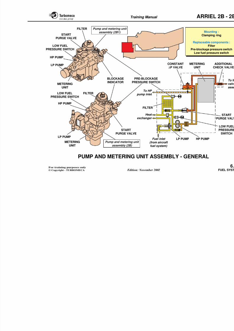
8/13/2019 Arriel_2B-2B1 11-02 En
http://slidepdf.com/reader/full/arriel2b-2b1-11-02-en 166/461
HP PUMPFuel inlet
LP PUMP
(driven)
BOOSTER PUMP PRESSURE
LOW PRESSURE
HIGH PRESSURE
METERED FUEL
CONSTANT
∆P VALVE
(in control)
ADDITIONALCHECK VALVE
(open)
VALVE(open)
STARTELECTRO-VAL
(ventilation posi
MANUAL CONTROL (2B)
AUTOMATIC BACK UP CONTROL (2B1)
P3 AIR
In the event of a control system failure,an automatic back-up control system
will ensure the correct fuel flow.
Restrictor
Training Manual ARR
FUEL SYSTEM - OPERATION (5)
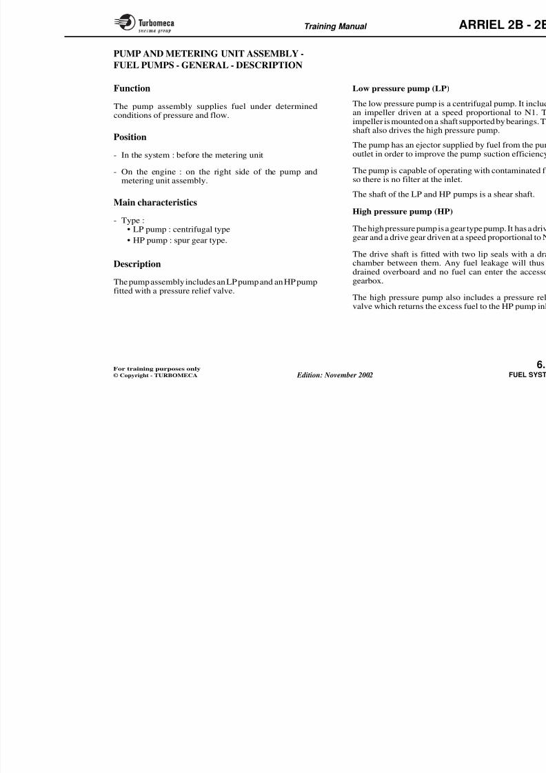
8/13/2019 Arriel_2B-2B1 11-02 En
http://slidepdf.com/reader/full/arriel2b-2b1-11-02-en 167/461
Shut-down
The engine stop command electrically supplies the stopelectro-valve and the stepper motor to close the meteringvalve.
The fuel supply to the injection wheel is cut and the enginestops.
The stop purge valve opens briefly to drain the fuel from
the injection line to the tank.
Note : The electrical signal to the stepper motor is delayed in order to detect a failure to close of the stop valve.
Training Manual ARR
STOP STOP
8/13/2019 Arriel_2B-2B1 11-02 En
http://slidepdf.com/reader/full/arriel2b-2b1-11-02-en 168/461
HP PUMP
LP PUMP(stopped)
ADDITIONALCHECK VALVE
(closed)
PURGE VALVE(open)
Momentary purge (to tank)
ELECTRO-VAL(electrically sup
The electrical signal to the stepper motor is
Restrictor
Training Manual ARR
PUMP AND METERING UNIT ASSEMBLY -
GENERAL
8/13/2019 Arriel_2B-2B1 11-02 En
http://slidepdf.com/reader/full/arriel2b-2b1-11-02-en 169/461
GENERAL
Function
The pump and metering unit assembly ensures fuel supplyand fuel flow metering.
Position
- In the system : before the fuel valve assembly
- On the engine : on the left front face of the accessorygearbox.
Main characteristics
- Mounting : clamping ring
- Replaceable components (LRUs):• Filter
• Pre-blockage pressure switch
• Low fuel pressure switch
• Fuel filter blockage indicator.
Main components
- LP pump
- Filter
- Pre-blockage pressure switch
- Blockage indicator
- Low fuel pressure switch
- Start purge valve
- HP pump
- Constant ∆P valve
- Metering unit
- Additional check valve.
Training Manual ARR
FILTER Pump and metering unit
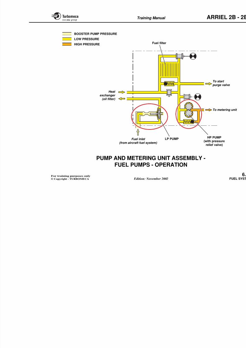
8/13/2019 Arriel_2B-2B1 11-02 En
http://slidepdf.com/reader/full/arriel2b-2b1-11-02-en 170/461
METERINGUNIT
MoClam
Replaceab
Pre-blockagLow fuel p
CONSTANT∆P VALVE
To HP
pump inlet
Heat
exchanger
LP PUMP
LP PUMP
HP PUMP
HP PUMP
BLOCKAGEINDICATOR
LOW FUELPRESSURE SWITCH
START
PURGE VALVE
START
PURGE VALVE
LOW FUELPRESSURE SWITCH
FILTER
FILTER
HP PUMLP PUMPFuel inlet
FILTER
PRE-BLOCKAGEPRESSURE SWITCH
METERINGUNIT
Pump and metering unit assembly (2B1)
Training Manual ARR
PUMP AND METERING UNIT ASSEMBLY -
FUEL PUMPS - GENERAL - DESCRIPTION
8/13/2019 Arriel_2B-2B1 11-02 En
http://slidepdf.com/reader/full/arriel2b-2b1-11-02-en 171/461
Function
The pump assembly supplies fuel under determinedconditions of pressure and flow.
Position
- In the system : before the metering unit
- On the engine : on the right side of the pump andmetering unit assembly.
Main characteristics
- Type :• LP pump : centrifugal type
• HP pump : spur gear type.
Description
The pump assembly includes an LP pump and an HP pumpfitted with a pressure relief valve.
Low pressure pump (LP)
The low pressure pump is a centrifugan impeller driven at a speed propimpeller is mounted on a shaft supporshaft also drives the high pressure pu
The pump has an ejector supplied byoutlet in order to improve the pump
The pump is capable of operating wiso there is no filter at the inlet.
The shaft of the LP and HP pumps i
High pressure pump (HP)
The high pressure pump is a gear type
gear and a drive gear driven at a speed
The drive shaft is fitted with two lichamber between them. Any fuel ldrained overboard and no fuel can gearbox.
The high pressure pump also includ
valve which returns the excess fuel t
Training Manual ARR
HP FUEL PUMP
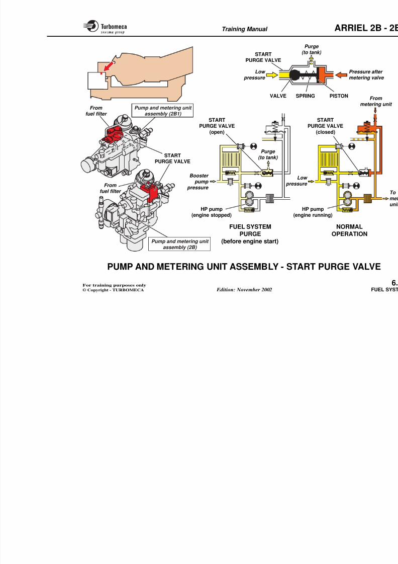
8/13/2019 Arriel_2B-2B1 11-02 En
http://slidepdf.com/reader/full/arriel2b-2b1-11-02-en 172/461
Fuel inlet
(from aircraft fuel system)
Ejector Impeller
Drive gDriven gear
HP FUEL PUMP
LP FUEL PUMP
HP PUMP
PRESSURERELIEF VALVE
Heat
exchanger (oil filter)
LP PUMFuel inlet
Filter
Type :LP pump : centrifugal type
2B1
2B
Training Manual ARR
PUMP AND METERING UNIT ASSEMBLY -
FUEL PUMPS - OPERATION
8/13/2019 Arriel_2B-2B1 11-02 En
http://slidepdf.com/reader/full/arriel2b-2b1-11-02-en 173/461
U U S O ON
Fuel from the aircraft system enters the LP pump whichprovides an initial pressure increase to supply the HPpump. The HP pump gives a second pressure rise andsupplies the metering unit.
The LP pump is capable of drawing fuel from the aircrafttank and therefore booster pumps are not necessary afterstarting.
LP pump operation
The centrifugal impeller draws the fuel in and forces it outtowards the heat exchanger.
The pump efficiency is improved by an ejector pump at itsinlet, supplied from the centrifugal impeller outlet.
The LP pump is said to be "transparent" as fuel can flowthrough it when it is not turning.
HP pump operationThe fuel arriving from the LP pump, vout under pressure by the HP pump t
The amount of fuel supplied by the puthan that required by the engine.
The HP pump is provided with a pre
the event of overpressure the valve opof the flow to the pump inlet. This vanormal engine running.
Training Manual ARR
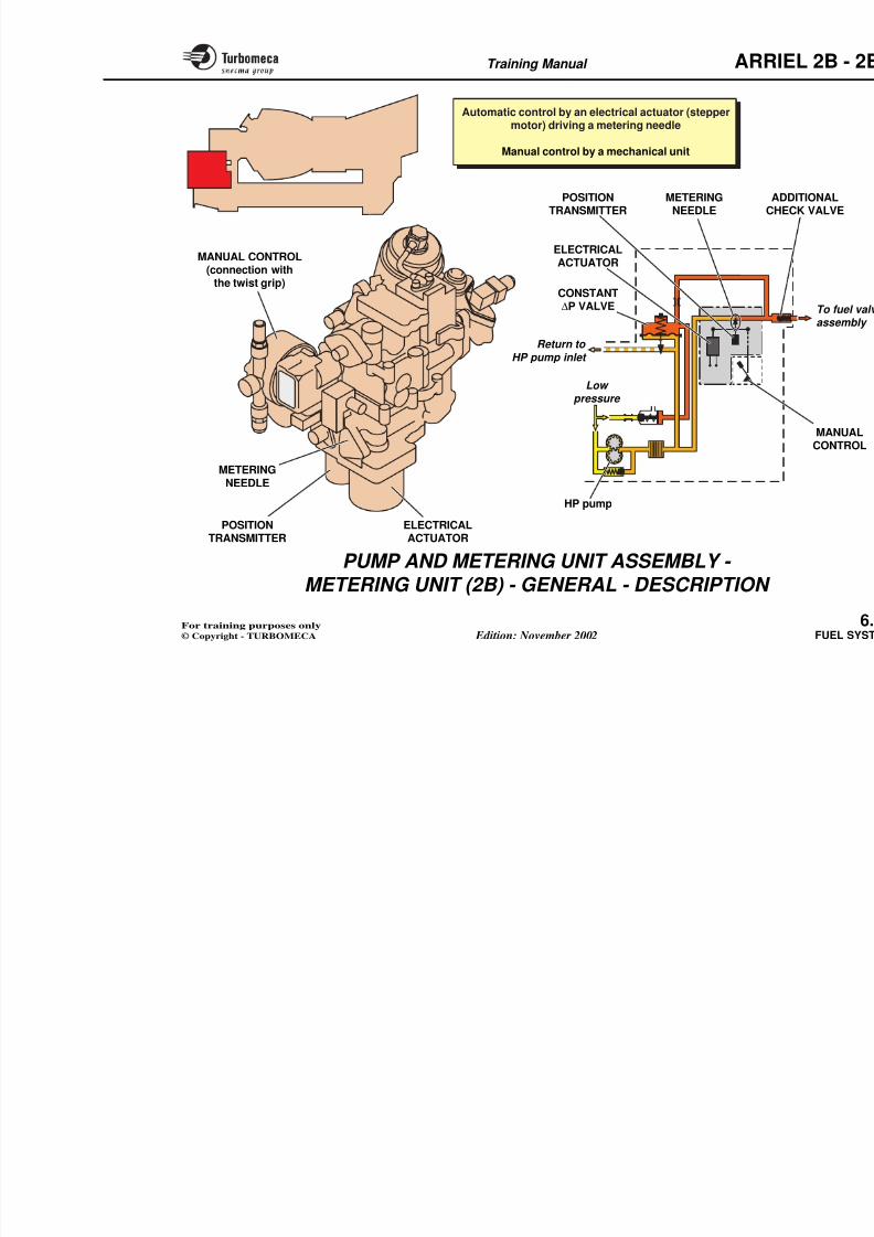
8/13/2019 Arriel_2B-2B1 11-02 En
http://slidepdf.com/reader/full/arriel2b-2b1-11-02-en 174/461
Fuel filter
HP PUM(with pres
relief va
LP PUMP
BOOSTER PUMP PRESSURE
LOW PRESSUREHIGH PRESSURE
Heat exchanger
(oil filter)
Fuel inlet (from aircraft fuel system)
To spur
To m
Training Manual ARR
PUMP AND METERING UNIT ASSEMBLY -
START PURGE VALVE
8/13/2019 Arriel_2B-2B1 11-02 En
http://slidepdf.com/reader/full/arriel2b-2b1-11-02-en 175/461
Function
The start purge valve permits a purge of air from the fuelsystem before engine start.
Position
- In the system : between the filter and the return line to the
fuel tank
- On the engine : on the upper part of the pump andmetering unit assembly.
Main characteristics
- Type : ball valve controlled by a piston and a spring.
Description
- A valve
- A piston
- A spring.
Operation
When the aircraft booster pump is supplied to the engine.
As soon as engine start is selected, HPon the piston to close the start purge
The start purge valve is open. The fueLP pump, the filter and return to the
Training Manual ARR
Purge (to tank)
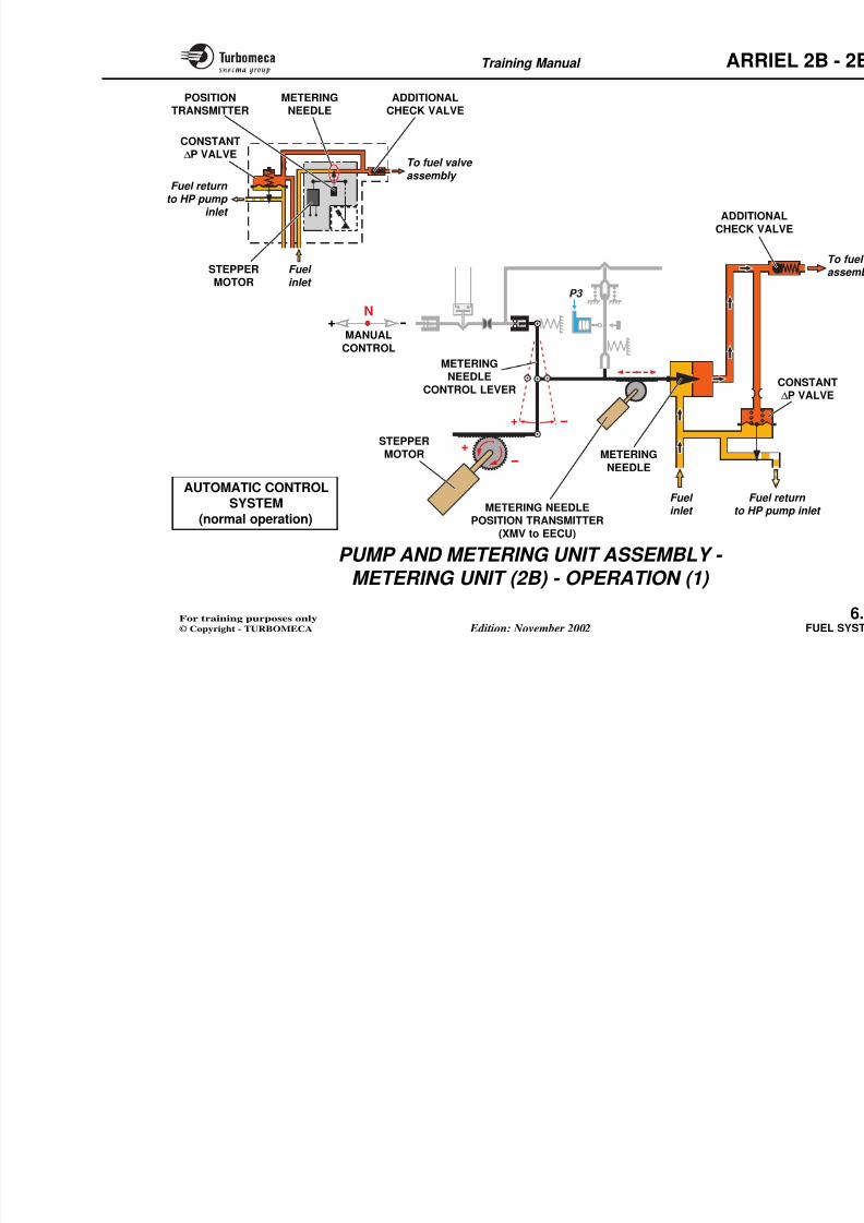
8/13/2019 Arriel_2B-2B1 11-02 En
http://slidepdf.com/reader/full/arriel2b-2b1-11-02-en 176/461
STARTPURGE VALVE
SPRING PISTONVALVE
Pm
Low pressure
STARTPURGE VALVE
(open)
FUEL SYSTEMPURGE
NORMOPERA
HP pump(engine stopped)
Booster pump
pressure
Purge (to tank)
STARTPURGE VALVE
(closed)
HP pump(engine running)
Low
pressure
(to tank)
Pump and metering unit assembly (2B1)
STARTPURGE VALVE
From fuel filter
From fuel filter
Training Manual ARR
PUMP AND METERING UNIT ASSEMBLY -
METERING UNIT (2B) - GENERAL -
8/13/2019 Arriel_2B-2B1 11-02 En
http://slidepdf.com/reader/full/arriel2b-2b1-11-02-en 177/461
DESCRIPTION
Function
The metering unit controls the fuel flow in automatic modein response to signals from the EECU.
In the event of control system failure, it permits fuel flowcontrol in manual mode.
Position
- In the system : downstream of the HP pump
- On the engine : at the front part of the pump and metering unit assembly.
Main characteristics
- Automatic control by an electrical actuator (stepper motor) driving a metering needle
- Manual control by a mechanical unit.
Description
- Actuator (automatic control)
- Metering needle (automatic and m
- Manual control system
- Metering needle position transmit
- Constant ∆P valve (common)
- Additional check valve (common).
Note : The position transmitter can
resolver.
Training Manual ARR
Automatic control by an electrical actuator (stepper
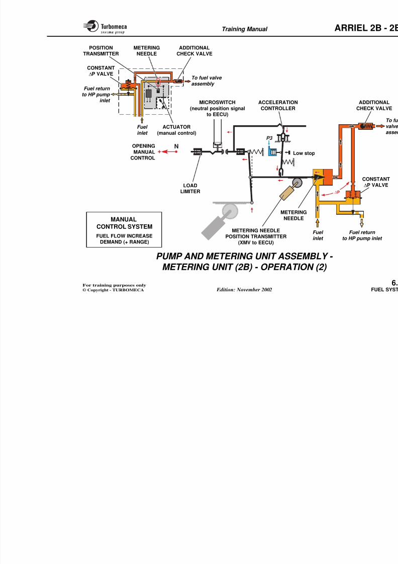
8/13/2019 Arriel_2B-2B1 11-02 En
http://slidepdf.com/reader/full/arriel2b-2b1-11-02-en 178/461
METERINGNEEDLE
Return to
HP pump inlet
Low pressure
HP pump
CONSTANT∆P VALVE
AC
POSITIONTRANSMITTER
Automatic control by an electrical actuator (steppermotor) driving a metering needle
Manual control by a mechanical unit
ELECTRICAL
ACTUATOR
METERINGNEEDLE
MANUAL CONTROL(connection withthe twist grip)
Training Manual ARR
PUMP AND METERING UNIT ASSEMBLY -
METERING UNIT (2B) - OPERATION (1)
8/13/2019 Arriel_2B-2B1 11-02 En
http://slidepdf.com/reader/full/arriel2b-2b1-11-02-en 179/461
This unit incorporates the automatic and manual control
systems in one unit.
The manual control is connected to a twist grip control onthe collective pitch lever
Automatic control system (normal operation)
The twist grip and manual system are in the "neutral" notch.
The manual control mechanism is "clutched" and,consequently, the upper end of the metering needle controllever is fixed. On the other hand, the acceleration controllever is kept away from the stops ; thus it does not offer anyresistance to the displacement of the metering needle.
The metering needle position is controlled by the stepper motor.
When the EECU commands a fuel flow increase thestepper motor rotates and through the rack and pinionmechanism, drives the metering needle open. The upper end of the vertical lever acts as a pivot point. The horizontalmetering needle rod has a rack and pinion mechanismwhich drives the position resolver which provides a
metering needle position signal to the EECU (XMV). For a fuel flow decrease, the system operates in the opposite
The constant ∆P valve returns the e
pump inlet and maintains a constant∆Pneedle. Thus fuel flow is only a functio
position, unaffected by change of ∆P
During shut-down the metering neeclosed position by the EECU.
During power-up, the metering nee permit engagement of the manual co
Training Manual ARR
METERINGNEEDLE
ADDITIONALCHECK VALVE
POSITIONTRANSMITTER
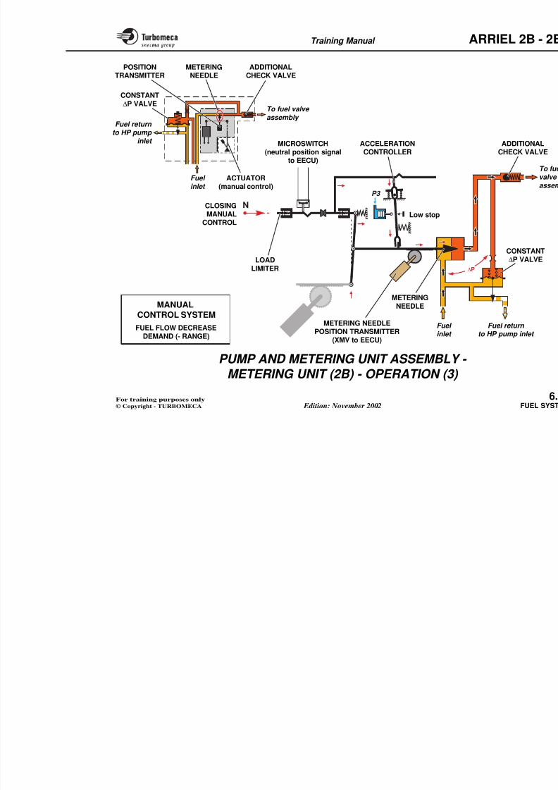
8/13/2019 Arriel_2B-2B1 11-02 En
http://slidepdf.com/reader/full/arriel2b-2b1-11-02-en 180/461
P3
+
+
-
-
+ -
N
Fuel return
to HP pump inlet
To fuel valve
assembly
CONSTANT∆P VALVE
C C
ADDITIO
CHECK V
S
MANUAL
CONTROL
METERING
NEEDLECONTROL LEVER
STEPPER
MOTOR
METERING NEEDLEFue
to HPFuel inlet
METERING
NEEDLE
STEPPERMOTOR
Fuel
inlet
AUTOMATIC CONTROLSYSTEM
Training Manual ARR
PUMP AND METERING UNIT ASSEMBLY - METERING UNIT (2B) - OPERATION (2)
8/13/2019 Arriel_2B-2B1 11-02 En
http://slidepdf.com/reader/full/arriel2b-2b1-11-02-en 181/461
Manual control system
Fuel flow increase demand (+ range)
The stepper motor is "frozen". The lower end of thetransmission system is then fixed and acts as a pivot.
When the manual control is moved, the accelerationcontroller lever is engaged onto the metering needle
control lever.
Thus the metering needle moves according to the manualcontrol until it reaches the P3 capsule stop.
This provides an instant step of fuel flow increase caused by the opening of the metering needle.
Should the manual control continue to move, thetransmission system would temporarily declutch.
The metering needle opening is afterwards controlled bythe capsule compression caused by the progressive increaseof the P3 air pressure.
Thus, the fuel flow required is obtained without surge or exceeding the limits.
The acceleration ends when the metering needle control
Training Manual ARR
METERINGNEEDLE
ADDITIONALCHECK VALVE
POSITIONTRANSMITTER
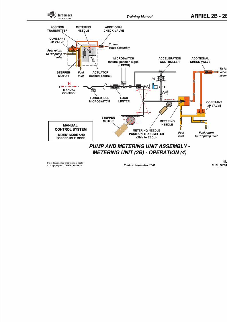
8/13/2019 Arriel_2B-2B1 11-02 En
http://slidepdf.com/reader/full/arriel2b-2b1-11-02-en 182/461
N+
∆P
P3
ACTUATOR
(manual control)
Fuel return
to HP pump inlet
To fuel valve
assembly
CONSTANT
∆P VALVE
NEEDLE CHECK VALVETRANSMITTER
Fuel
inlet
OPENING
MANUALCONTROL
METERING NEEDLEPOSITION TRANSMITTER
FFuel
ACCELERATION
CONTROLLER
Low stop
MICROSWITCH
(neutral position signalto EECU)
LOADLIMITER
METERING
NEEDLEMANUAL
CONTROL SYSTEMFUEL FLOW INCREASE
Training Manual ARR
PUMP AND METERING UNIT ASSEMBLY - METERING UNIT (2B) - OPERATION (3)
8/13/2019 Arriel_2B-2B1 11-02 En
http://slidepdf.com/reader/full/arriel2b-2b1-11-02-en 183/461
Manual control system (continued)
Fuel flow decrease demand (- range)
The stepper motor is "frozen". The lower end of thetransmission system is then fixed and acts as a pivot.
The clutch transmission system is pushed by the twist grip.
The acceleration controller lever is engaged onto themetering needle control lever.
Thus the metering needle moves with to the manual controluntil it reaches the fixed low stop.
If the metering needle reaches the low stop, the transmissionsystem is declutched in order to limit the stresses on themechanical lever.
In the case of sudden control movement, the load limiter reduces the load on the pump and metering unit assemblyinternal mechanism.
Training Manual ARR
METERINGNEEDLE
ADDITIONALCHECK VALVE
POSITIONTRANSMITTER
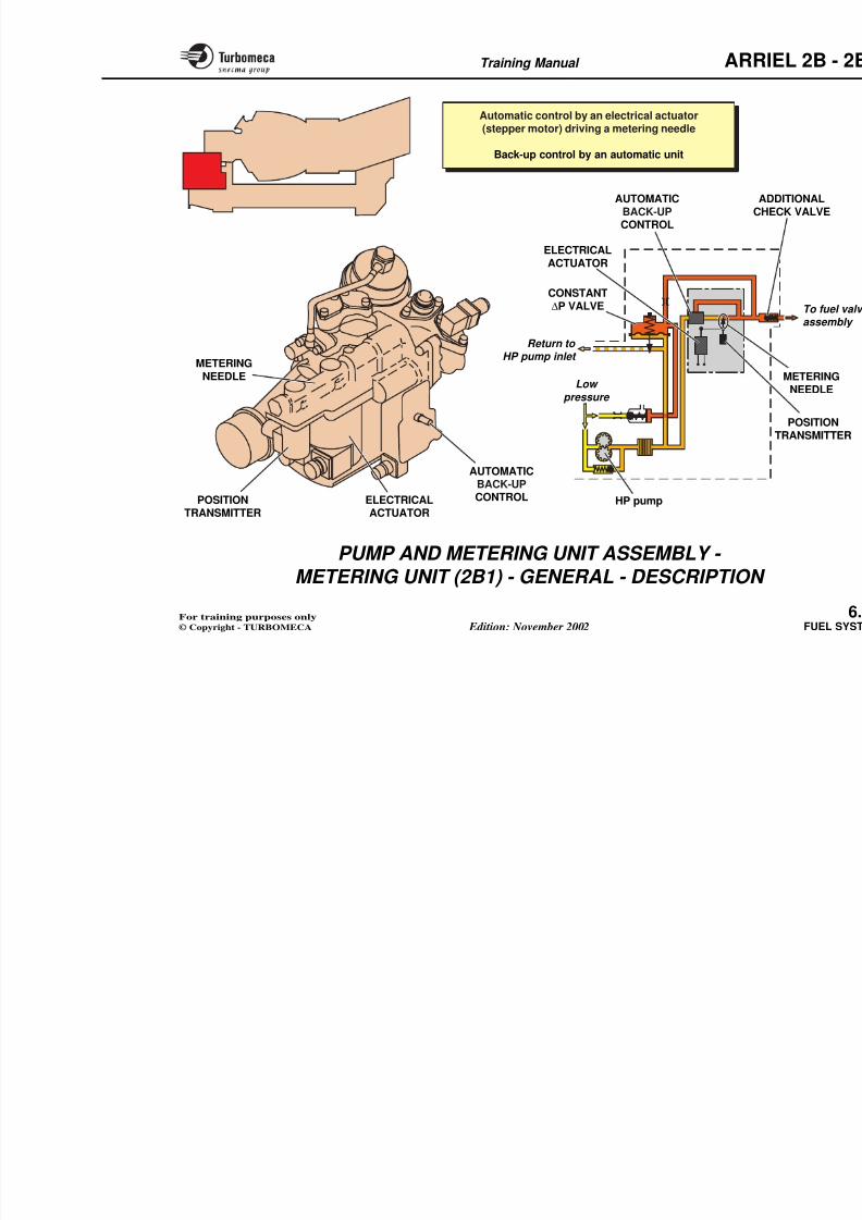
8/13/2019 Arriel_2B-2B1 11-02 En
http://slidepdf.com/reader/full/arriel2b-2b1-11-02-en 184/461
∆P
N-
P3
ACTUATOR(manual control)
Fuel return to HP pump
inlet
To fuel valve
assembly
CONSTANT∆P VALVE
NEEDLE CHECK VALVETRANSMITTER
Fuel inlet
CLOSINGMANUAL
CONTROL
METERING NEEDLEPOSITION TRANSMITTER
FuFuel
ACCELERATIONCONTROLLER
Low stop
MICROSWITCH(neutral position signal
to EECU)
LOADLIMITER
METERINGNEEDLEMANUAL
CONTROL SYSTEMFUEL FLOW DECREASE
Training Manual ARR
PUMP AND METERING UNIT ASSEMBLY - METERING UNIT (2B) - OPERATION (4)
8/13/2019 Arriel_2B-2B1 11-02 En
http://slidepdf.com/reader/full/arriel2b-2b1-11-02-en 185/461
Manual control system (continued)
"Mixed" mode
During normal operation (automatic mode), if the twist grip is moved out of the neutral notch :
- The neutral position switch sends a signal to the EECU
- The stepper motor continues to operate
- The EECU outputs a signal to the cockpit.
Any variation of fuel flow commanded by the twist grip willbe automatically compensated by the EECU.
Consequently the N1 and the power delivered by theengine will still be controlled by the EECU.
Forced idle mode
To permit autorotation training, a idle) is operated at the end of movemin the flow decrease direction. When toutput to the EECU causes the softwengine to idle (67 % N1). The engin
power to the aircraft transmission possible. Return to normal flight powthe twist grip is moved off the minmicroswitch opens.
Training Manual ARR
METERINGNEEDLE
ADDITIONALCHECK VALVE
POSITIONTRANSMITTER
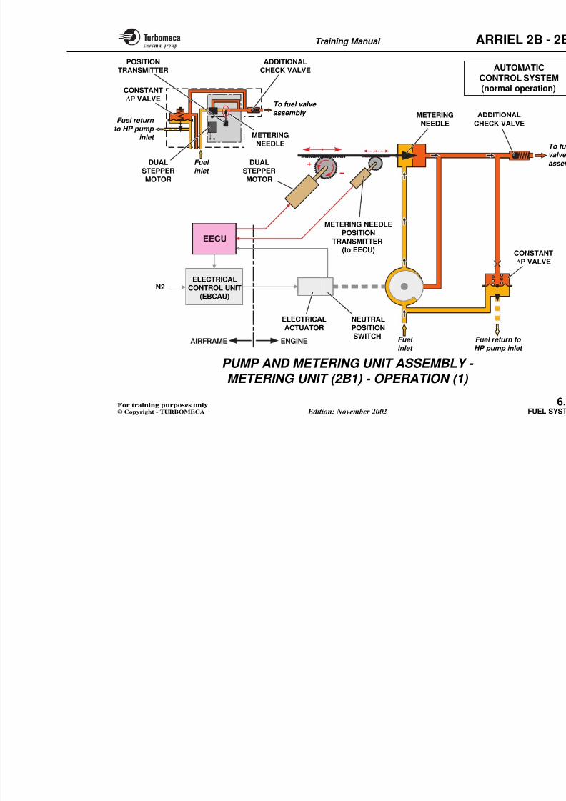
8/13/2019 Arriel_2B-2B1 11-02 En
http://slidepdf.com/reader/full/arriel2b-2b1-11-02-en 186/461
+ -
N
+
+
-
-
+ -
P3
MANUAL
CONTROL SYSTEM"MIXED" MODE AND
Fuel return to HP pump
inlet
To fuel
valve assembly
CONSTANT∆P VALVE
NEEDLE CHECK VALVE
ADDITICHECK
TRANSMITTER
MANUALCONTROL
STEPPERMOTOR
METERING NEEDLEPOSITION TRANSMITTER FuFuel
METERINGNEEDLE
STEPPERMOTOR
Fuel inlet
ACTUATOR(manual control)
ACCELERATIONCONTROLLER
LOADLIMITERFORCED IDLEMICROSWITCH
MICROSWITCH(neutral position signal
to EECU)
8/13/2019 Arriel_2B-2B1 11-02 En
http://slidepdf.com/reader/full/arriel2b-2b1-11-02-en 187/461
Training Manual ARR
Automatic control by an electrical actuator
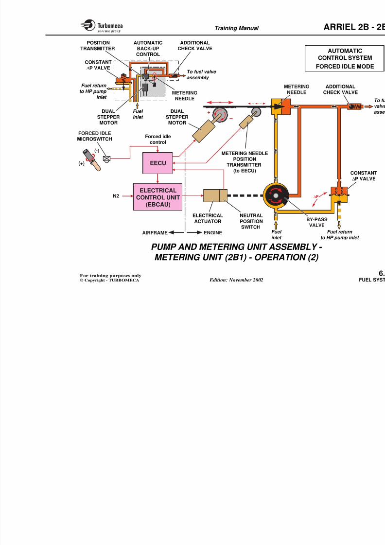
8/13/2019 Arriel_2B-2B1 11-02 En
http://slidepdf.com/reader/full/arriel2b-2b1-11-02-en 188/461
METERING
NEEDLE
POSITIONTRANSMITTER
Return to HP pump inlet
Low
pressure
HP pump
CONSTANT∆P VALVE
ELECTRICALACTUATOR
ACH
uto at c co t o by a e ect ca actuato(stepper motor) driving a metering needle
Back-up control by an automatic unit
ELECTRICAL
ACTUATOR
AUTOMATICBACK-UPCONTROL
AUTOMATICBACK-UPCONTROL
Training Manual ARR
PUMP AND METERING UNIT ASSEMBLY -
METERING UNIT (2B1) - OPERATION (1)
8/13/2019 Arriel_2B-2B1 11-02 En
http://slidepdf.com/reader/full/arriel2b-2b1-11-02-en 189/461
This unit incorporates the normal automatic control and
the mechanical part of the back-up control system in oneunit.
Automatic control system
Normal operation
In normal operation, the by-pass valve is closed to by-passand fully open to metering needle supply. This is theneutral position.
The metering needle position is controlled by the stepper motor.
When the EECU commands a fuel flow increase, thestepper motor rotates and through the rack and pinion
mechanism, drives the metering needle open. The meteringneedle rod movement drives the resolver through a rack and pinion which provides a metering needle positionsignal to the EECU. For a fuel flow decrease, the systemoperates in the opposite sense.
The constant ∆P valve returns the excess fuel to the HP pump inlet and maintains a constant pressure drop acrossthe metering needle. Thus fuel flow is only a function of
metering needle position, unaffected by changes of ∆P.
D i h d h i dl i d h
Note : NPS: Neutral position switch
Training Manual ARR
ADDITIONALCHECK VALVE
POSITIONTRANSMITTER A
CONT
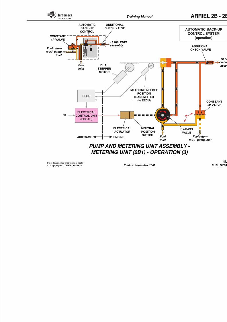
8/13/2019 Arriel_2B-2B1 11-02 En
http://slidepdf.com/reader/full/arriel2b-2b1-11-02-en 190/461
N2
+
-
Fuel return to HP pump
inlet
To fuel valve
assembly
CONSTANT∆P VALVE
METERINGNEEDLE
ADDITICHECK
METERING NEEDLEPOSITION
TRANSMITTER(to EECU)
ELECTRICALACTUATOR
METERINGNEEDLE
DUAL
STEPPERMOTOR
Fuel
inlet
NEUTRALPOSITIONSWITCH
CONT(norm
DUAL
STEPPERMOTOR
EECU
ELECTRICALCONTROL UNIT
(EBCAU)
Training Manual ARR
PUMP AND METERING UNIT ASSEMBLY - METERING UNIT (2B1) - OPERATION (2)
8/13/2019 Arriel_2B-2B1 11-02 En
http://slidepdf.com/reader/full/arriel2b-2b1-11-02-en 191/461
Automatic control system (continued) Forced idle mode
To permit autorotation training, a microswitch (forced idle) is operated at the end of movement of the twist gripin the flow decrease direction. When this switch is closed its output to the EECU causes the software to deceleratethe engine to idle (67 % N1).
The engine no longer supplies power to the aircraft transmission and autorotation is possible.
Return to normal flight power is made as soon as the twist grip is moved off the microswitch.
Training Manual ARR
AUTO
ADDITIONALCHECK VALVE
POSITIONTRANSMITTER
AUTOMATICBACK-UP
CONTROL
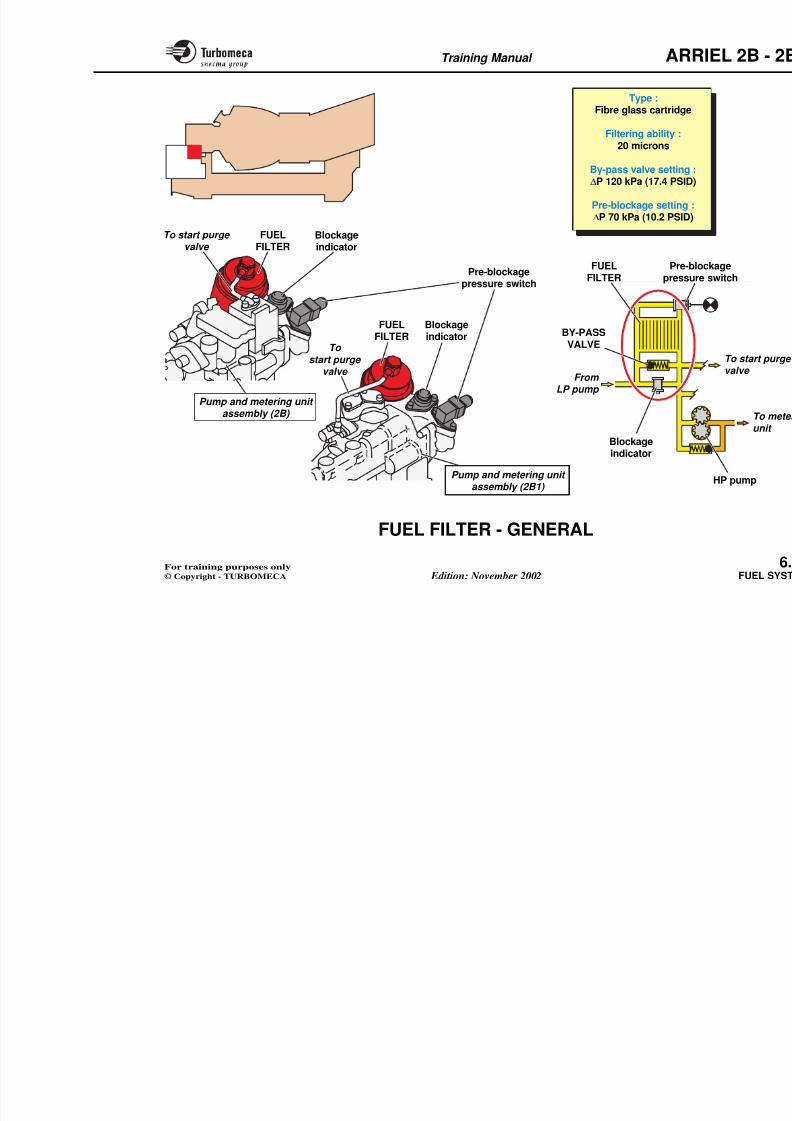
8/13/2019 Arriel_2B-2B1 11-02 En
http://slidepdf.com/reader/full/arriel2b-2b1-11-02-en 192/461
+
-
∆P+-
N2
CONTRO
FORCED
Fuel return
to HP pump inlet
To fuel valve
assembly
CONSTANT∆P VALVE
METERINGNEEDLE
ADDIT
CHECK
CONTROL
METERING NEEDLEPOSITION
TRANSMITTER
(to EECU)
METERING
NEEDLE
DUAL
STEPPERMOTOR
Fuel
inlet
DUAL
STEPPERMOTOR
BY-PASSVALVE
Forced idlecontrol
FORCED IDLEMICROSWITCH
(+)
(-)
ELECTRICAL
ACTUATOR
NEUTRAL
POSITIONSWITCH
EECU
ELECTRICALCONTROL UNIT
(EBCAU)
Training Manual ARR
PUMP AND METERING UNIT ASSEMBLY -
METERING UNIT (2B1) - OPERATION (3)
8/13/2019 Arriel_2B-2B1 11-02 En
http://slidepdf.com/reader/full/arriel2b-2b1-11-02-en 193/461
Automatic back-up control system
The automatic back-up system includes an electrical controlunit (EBCAU) in the aircraft and an electrical actuator
fitted on the pump and metering unit assembly linked to ametering needle by-pass valve.
In the unlikely event of a total EECU failure, the stepper motor will be frozen and the back-up system will maintain
N2 at 100 %. The electrical control unit receives a signalof N2 from the engine.
If the N2 decreases, it will command the actuator to openthe by-pass thus permitting an increased fuel flow in by-
pass of the metering needle.
If the N2 increases, the control unit will command the
actuator to rotate the by-pass valve in the opposite direction.This will reduce the flow to the main metering needlewithout opening the by-pass.
The rate of engine acceleration and deceleration is a function of the speed of movement of the actuator which isdesigned to avoid the possibility of surge or flame-out.
Note : The electrical control unit Back-up Control Auxiliary Unactuator are supplied by the ai
Training Manual ARR
AUTOMATCONTRO
ADDITIONALCHECK VALVE
AUTOMATICBACK-UP
CONTROL
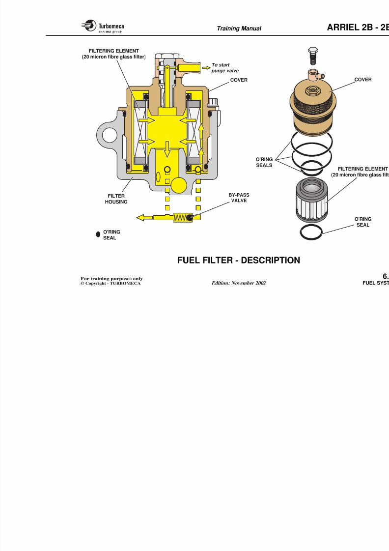
8/13/2019 Arriel_2B-2B1 11-02 En
http://slidepdf.com/reader/full/arriel2b-2b1-11-02-en 194/461
+-
∆PN2
CONTRO
(ope
Fuel return
to HP pump inlet
To fuel valve assembly
CONSTANT
∆P VALVE
ADDITICHECK
CONTROL
Fuel
inlet
BY-PASSVALVE
METERING NEEDLE
POSITIONTRANSMITTER
(to EECU)
DUAL
STEPPERMOTOR
ELECTRICALACTUATOR NEUTRALPOSITION
SWITCH
EECU
ELECTRICALCONTROL UNIT
(EBCAU)
Training Manual ARR
FUEL FILTER - GENERAL
Function Main components
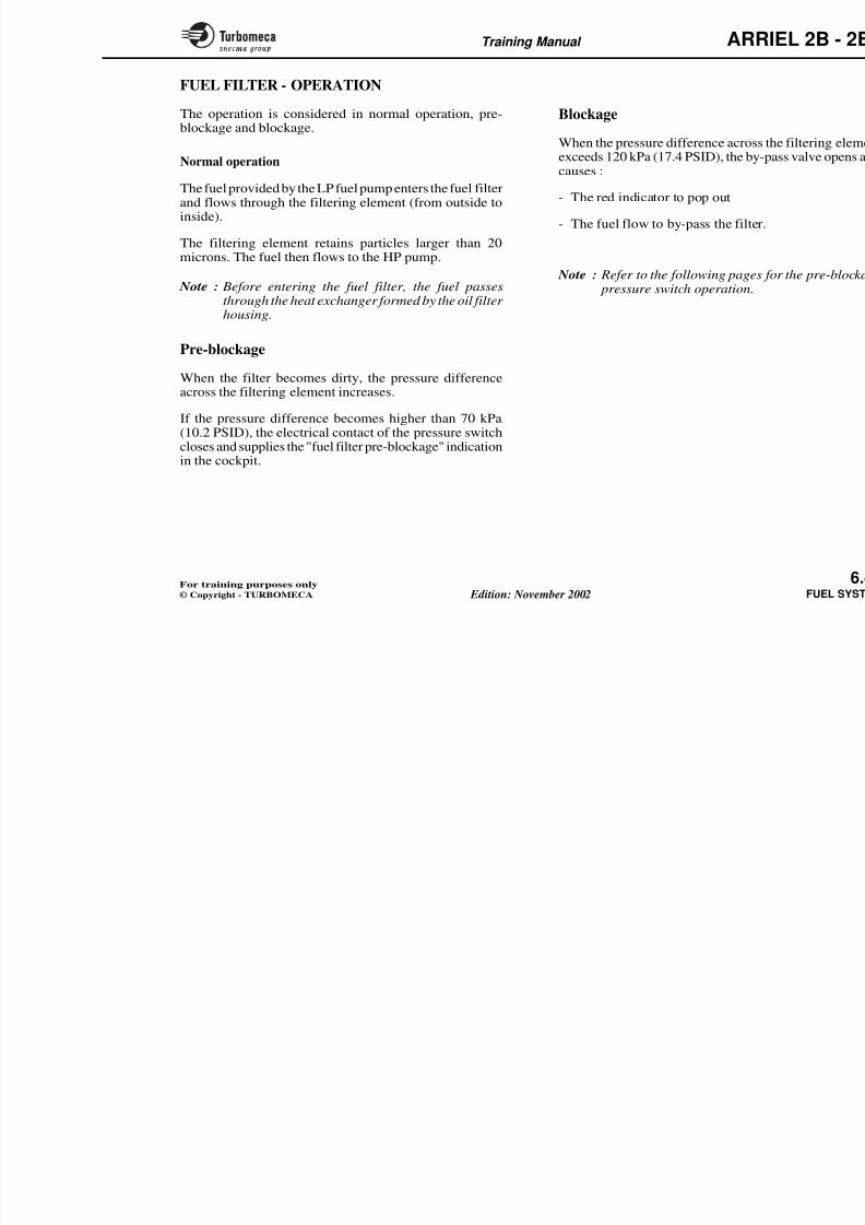
8/13/2019 Arriel_2B-2B1 11-02 En
http://slidepdf.com/reader/full/arriel2b-2b1-11-02-en 195/461
Function
The filter retains any particles that may be in the fuel inorder to protect the metering unit components.
Position
- In the system : between the LP and HP pumps
- On the engine : on top of the pump and metering unitassembly.
Main characteristics
- Type : fibre glass cartridge
- Filtering ability : 20 microns
- By-pass valve setting : ∆P 120 kPa (17.4 PSID)
- Pre-blockage pressure switch setting : ∆P 70 kPa(10.2 PSID).
Main components
- Filter
- Blockage indicator
- By-pass valve
- Pre-blockage pressure switch
- Cover with union (supply to start p
Training Manual ARR
Type :Fibre glass cartridge
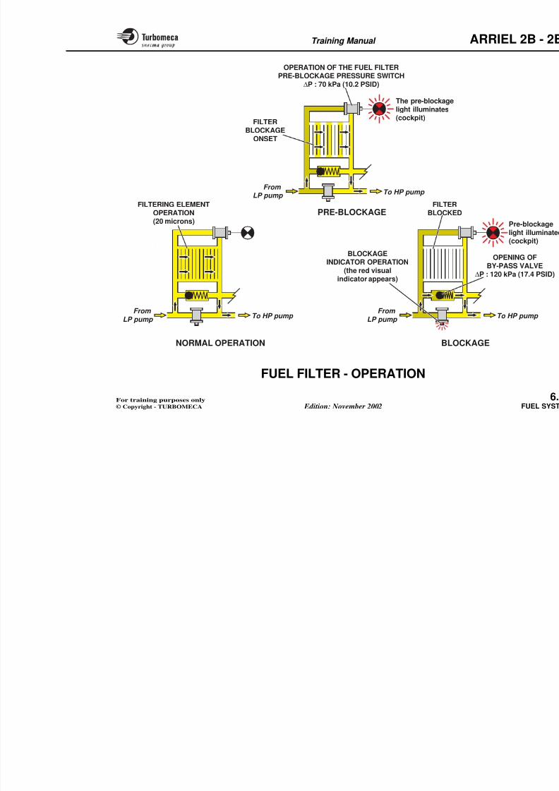
8/13/2019 Arriel_2B-2B1 11-02 En
http://slidepdf.com/reader/full/arriel2b-2b1-11-02-en 196/461
g g
Filtering ability :20 microns
By-pass valve setting :∆P 120 kPa (17.4 PSID)
Pre-blockage setting :∆P 70 kPa (10.2 PSID)
From LP pump
Pre-blopressure
Blockage
indicator
FUELFILTER
BY-PASS
VALVE
Blockageindicator
Blockageindicator
Pump and metering unit assembly (2B)
FUELFILTER
FUELFILTER
Pre-blockagepressure switch
To start purge valve
To start purge
valve
Training Manual ARR
FUEL FILTER - DESCRIPTION
The assembly comprises the housing, the filtering element,th b l th bl k it h d
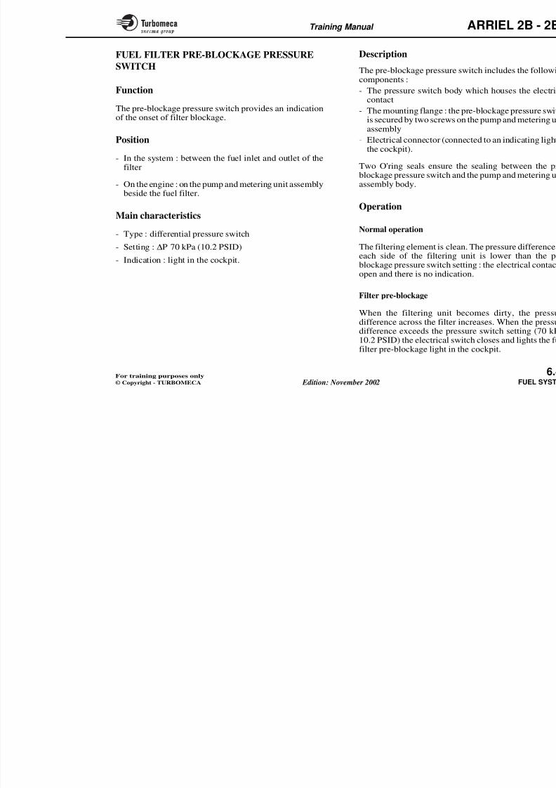
8/13/2019 Arriel_2B-2B1 11-02 En
http://slidepdf.com/reader/full/arriel2b-2b1-11-02-en 197/461
the by-pass valve, the pre-blockage pressure switch and
the blockage indicator.
Filtering element
It is a fibre glass cartridge with a filtering ability of 20microns.
O'ring seals ensure the sealing between the cartridge and
the filter housing.
The filter cover is fitted with a purge outlet union.
By-pass valve
This valve ensures a fuel flow to the metering unit in theevent of filter blockage. It is subjected on one side to filter
upstream pressure and on the other side to downstreampressure plus the force of a spring.
Note : The by-pass valve is fitted inside the pump and metering unit assembly body.
Training Manual ARR
FILTERING ELEMENT(20 micron fibre glass filter)
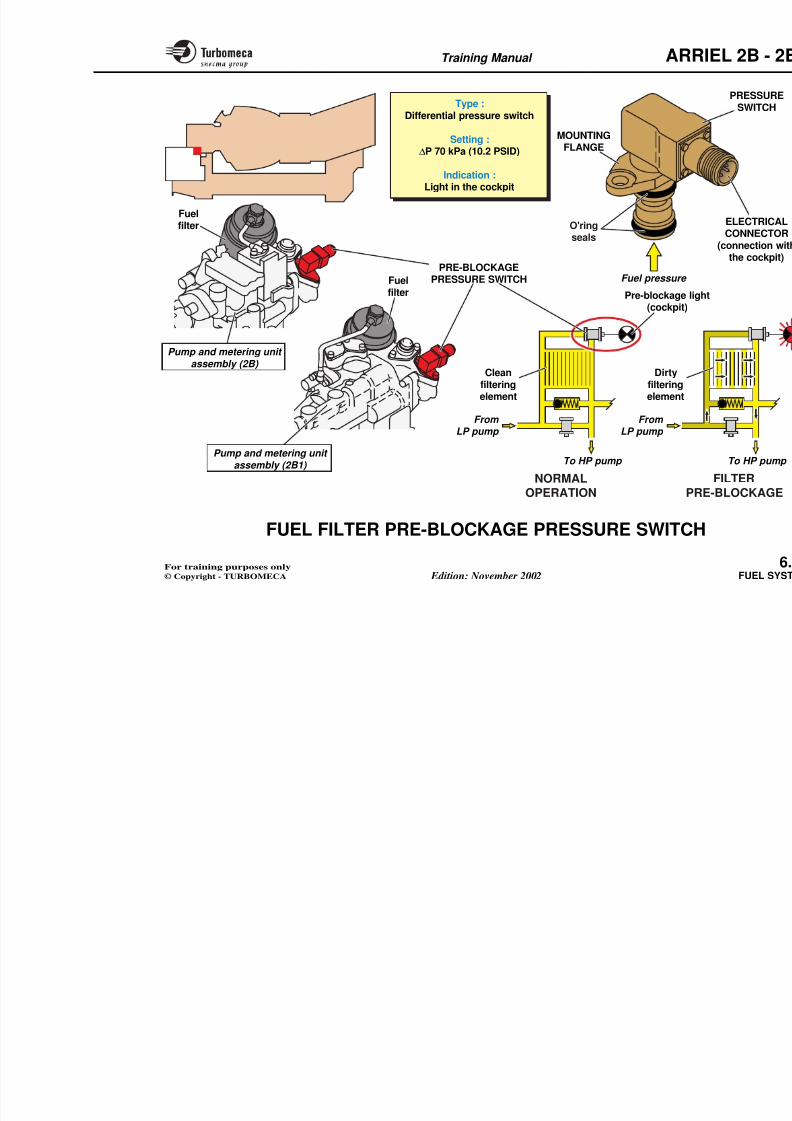
8/13/2019 Arriel_2B-2B1 11-02 En
http://slidepdf.com/reader/full/arriel2b-2b1-11-02-en 198/461
(20 micron fibre glass filter)
FIL(20 m
O'RING
O'RINGSEALS
FILTERHOUSING
To start purge valve
COVER
BY-PASSVALVE
Training Manual ARR
FUEL FILTER - OPERATION
The operation is considered in normal operation, pre-blockage and blockage
Blockage
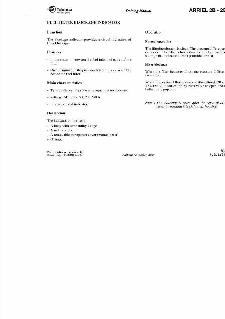
8/13/2019 Arriel_2B-2B1 11-02 En
http://slidepdf.com/reader/full/arriel2b-2b1-11-02-en 199/461
blockage and blockage.
Normal operation
The fuel provided by the LP fuel pump enters the fuel filterand flows through the filtering element (from outside toinside).
The filtering element retains particles larger than 20
microns. The fuel then flows to the HP pump.
Note : Before entering the fuel filter, the fuel passesthrough the heat exchanger formed by the oil filter housing.
Pre-blockage
When the filter becomes dirty, the pressure differenceacross the filtering element increases.
If the pressure difference becomes higher than 70 kPa(10.2 PSID), the electrical contact of the pressure switchcloses and supplies the "fuel filter pre-blockage" indicationin the cockpit.
When the pressure difference across exceeds 120 kPa (17.4 PSID), the by-causes :
- The red indicator to pop out
- The fuel flow to by-pass the filter.
Note : Refer to the following pages f pressure switch operation.
Training Manual ARR
OPERATION OF THE FUEL FILTERPRE-BLOCKAGE PRESSURE SWITCH
∆P 70 kP (10 2 PSID)
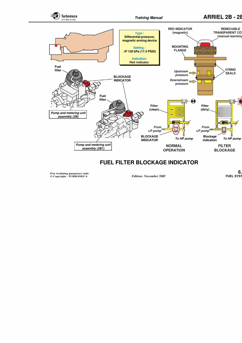
8/13/2019 Arriel_2B-2B1 11-02 En
http://slidepdf.com/reader/full/arriel2b-2b1-11-02-en 200/461
FILTERBLOCKAGE
ONSET
The pre-blockagelight illuminates(cockpit)
From
LP pump To HP pump
FILTERING ELEMENTOPERATION(20 microns)
BLOCKAGEINDICATOR OPERATION
(the red visualindicator appears)
FromLP pump
To HP pump
∆P : 70 kPa (10.2 PSID)
PRE-BLOCKAGE
OBY
∆P : 12
From
LP pump
FILTERBLOCKED
Training Manual ARR
FUEL FILTER PRE-BLOCKAGE PRESSURE
SWITCH
Description
The pre-blockage pressure switch incomponents :
8/13/2019 Arriel_2B-2B1 11-02 En
http://slidepdf.com/reader/full/arriel2b-2b1-11-02-en 201/461
FunctionThe pre-blockage pressure switch provides an indicationof the onset of filter blockage.
Position
- In the system : between the fuel inlet and outlet of the
filter
- On the engine : on the pump and metering unit assemblybeside the fuel filter.
Main characteristics
- Type : differential pressure switch
- Setting : ∆P 70 kPa (10.2 PSID)
- Indication : light in the cockpit.
p
- The pressure switch body which hcontact
- The mounting flange : the pre-blocis secured by two screws on the pumassembly
- Electrical connector (connected to the cockpit).
Two O'ring seals ensure the sealinblockage pressure switch and the pumassembly body.
Operation
Normal operation
The filtering element is clean. The preach side of the filtering unit is lblockage pressure switch setting : theopen and there is no indication.
Filter pre-blockage
When the filtering unit becomes difference across the filter increasesdifference exceeds the pressure swi
Training Manual ARR
Type :Differential pressure switch
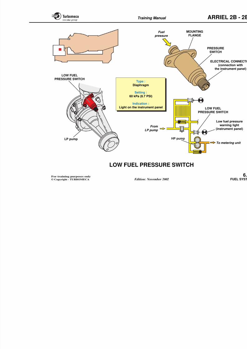
8/13/2019 Arriel_2B-2B1 11-02 En
http://slidepdf.com/reader/full/arriel2b-2b1-11-02-en 202/461
Pump and metering unit
assembly (2B)
Pump and metering unit assembly (2B1)
MOUNTINGFLANGE
O'ring
seals
Differential pressure switch
Setting :∆P 70 kPa (10.2 PSID)
Indication :Light in the cockpit
Fuelfilter
Fuelfilter
To HP pump
From LP pump
From LP pump
Fuel pressure
Cleanfilteringelement
Pre-blockage lig(cockpit)
Dirtyfilteringelement
PRE-BLOCKAGEPRESSURE SWITCH
Training Manual ARR
FUEL FILTER BLOCKAGE INDICATOR
Function Operation
8/13/2019 Arriel_2B-2B1 11-02 En
http://slidepdf.com/reader/full/arriel2b-2b1-11-02-en 203/461
The blockage indicator provides a visual indication of filter blockage.
Position
- In the system : between the fuel inlet and outlet of thefilter
- On the engine : on the pump and metering unit assemblybeside the fuel filter.
Main characteristics
- Type : differential pressure, magnetic arming device
- Setting :∆
P 120 kPa (17.4 PSID)
- Indication : red indicator.
Decription
The indicator comprises :
- A body with a mounting flange
- A red indicator
A bl ( l )
p
Normal operation
The filtering element is clean. The preach side of the filter is lower than thsetting : the indicator doesn't protrud
Filter blockage
When the filter becomes dirty, the increases.
When the pressure difference exceeds17.4 PSID) it causes the by-pass vaindicator to pop out.
Note : The indicator is reset, aftercover by pushing it back into
Training Manual ARR
RED INDICATOR(magnetic) TType :
Differential pressure
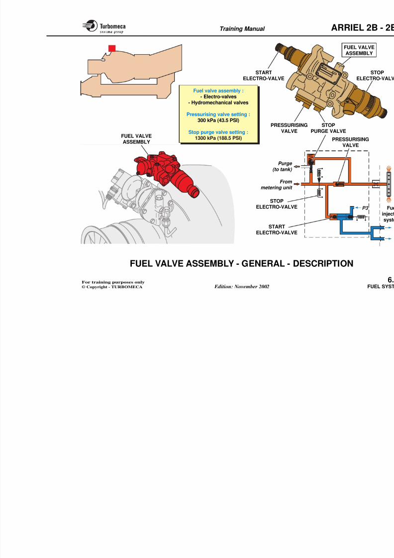
8/13/2019 Arriel_2B-2B1 11-02 En
http://slidepdf.com/reader/full/arriel2b-2b1-11-02-en 204/461
MOUNTINGFLANGE
Upstream
pressure
Downstream pressure
Differential pressure,
magnetic arming device
Setting :∆P 120 kPa (17.4 PSID)
Indication:Red indicator
BLOCKAGEINDICATOR
BlockagindicatioTo HP pump
From
LP pump
From
LP pump
Filter(clean)
Filter(dirty)
BLOCKAGEINDICATOR
Pump and metering unit assembly (2B)
Fuelfilter
Fuelfilter
P d i i
Training Manual ARR
LOW FUEL PRESSURE SWITCH
Function Description
8/13/2019 Arriel_2B-2B1 11-02 En
http://slidepdf.com/reader/full/arriel2b-2b1-11-02-en 205/461
The low fuel pressure switch detects low pressure at the LPpump outlet.
Position
- In the system : upstream of the HP pump
- On the engine : on the pump and metering unit assemblyfront face above the LP pump.
Main characteristics
- Type : diaphragm
- Setting : 60 kPa (8.7 PSI)
- Indication : light on the instrument panel.
The pressure switch includes :
- A fuel inlet orifice
- A diaphragm and a microswitch
- An electrical connector (connectionpanel).
The low fuel pressure switch is securepump and metering unit assembly fr
Operation
Normal engine running
In normal operation the fuel pressurethe electrical contact open.
The warning light on the instrument p
Low pressure operation
If the fuel filter downstream pressure
(8.7 PSI), the electrical contact closecircuit to the low fuel pressure warni
Training Manual ARR
MOUNTING
FLANGEFuel
pressure
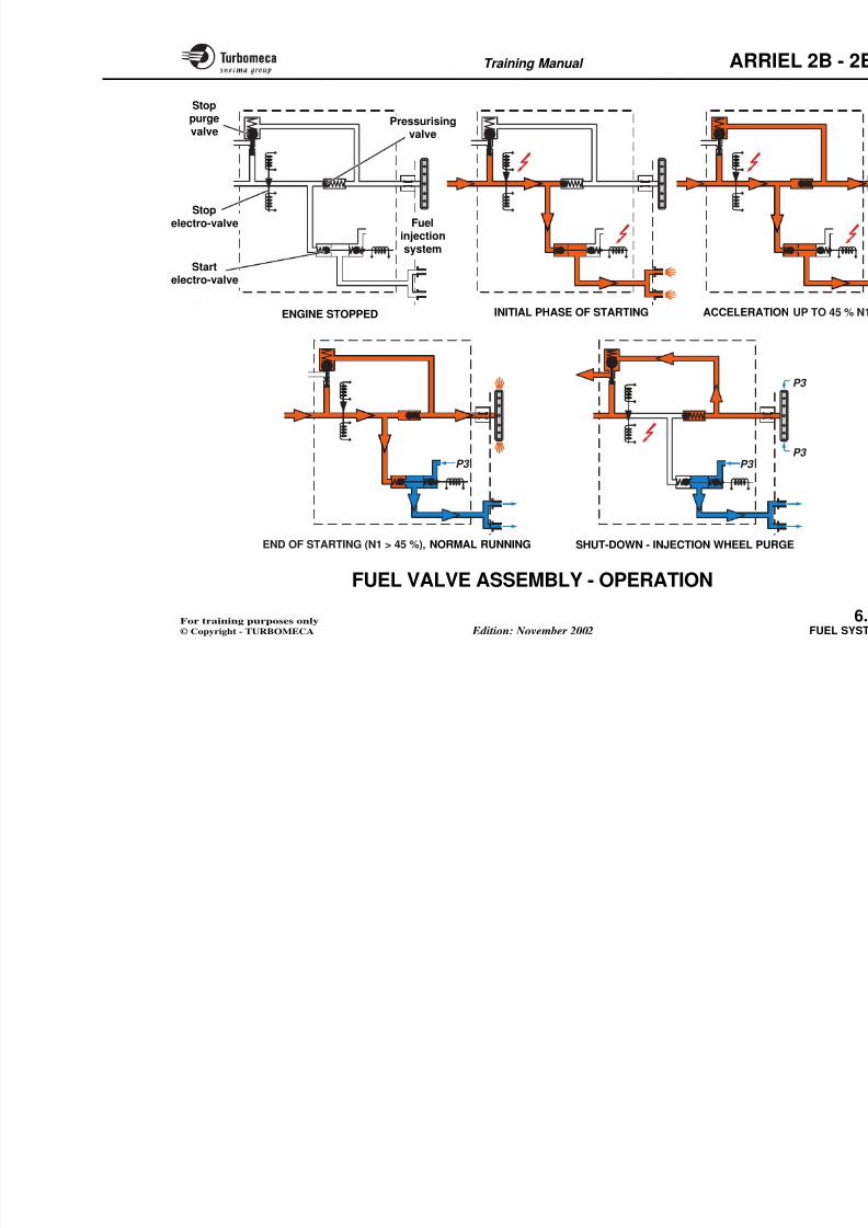
8/13/2019 Arriel_2B-2B1 11-02 En
http://slidepdf.com/reader/full/arriel2b-2b1-11-02-en 206/461
Type :
Diaphragm
Setting :
60 kPa (8.7 PSI)
Indication :
Light on the instrument panel
PRESSUSWITC
LOW FUELPRESSURE SWITCH
LOW FUEPRESSURE SW
ELEC(
the
To
From
LP pump
HP pumpLP pump
Lo
(in
Training Manual ARR
FUEL VALVE ASSEMBLY - GENERAL -
DESCRIPTION
Start electro-valve
8/13/2019 Arriel_2B-2B1 11-02 En
http://slidepdf.com/reader/full/arriel2b-2b1-11-02-en 207/461
FunctionThe fuel valve assembly distributes the fuel to the injectionsystem.
Position
- In the system : between the metering unit and the
injection system
- On the engine : on a support at the upper part of thecentrifugal compressor casing.
Main characteristics
- Assembly which comprises electro-valves and
hydromechanical valves
- Setting of the pressurising valve : 300 kPa (43.5 PSI)
- Setting of the stop purge valve : 1300 kPa (188.5 PSI).
Description
This assembly includes the start electro-valve, the stopelectro-valve, the pressurising valve and the stop purge
This valve allows either fuel or airinjectors. It is a 3-way, mono-stable vsolenoid which controls a double vaare : the fuel inlet, the air inlet aninjectors.
Stop electro-valve
This valve controls the fuel flow to this a bi-stable type valve and consists ocoils (open and close) and a two pos
Pressurising valve
During starting it ensures priority
injectors. It is a ball valve which is sp
Stop purge valve
It is a ball valve which is spring loadedcentrifugal injection wheel during eprevent carbonisation of residual fue
Training Manual ARR
FUA
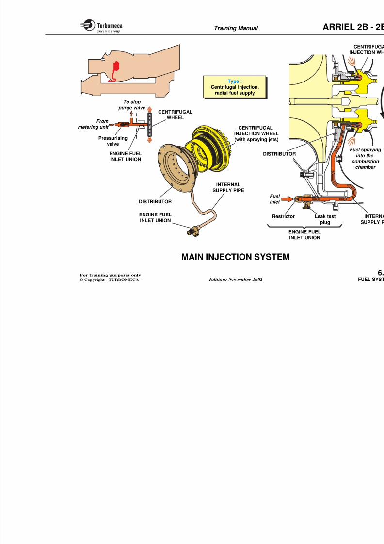
8/13/2019 Arriel_2B-2B1 11-02 En
http://slidepdf.com/reader/full/arriel2b-2b1-11-02-en 208/461
Fuel valve assembly :- Electro-valves
- Hydromechanical valves
Pressurising valve setting :
300 kPa (43.5 PSI)
Stop purge valve setting :1300 kPa (188.5 PSI)
PRESSURISINGVALVE
STARTELECTRO-VALVE
FUEL VALVEASSEMBLY
STOPPURGE VALVE
STARTELECTRO-VALVE
From metering unit
Purge
(to tank)
PRESSVA
STOPELECTRO-VALVE
Training Manual ARR
FUEL VALVE ASSEMBLY - OPERATION
The following phases are considered : starting, normalrunning and shut-down.
Shut-down - Injection wheel pur
8/13/2019 Arriel_2B-2B1 11-02 En
http://slidepdf.com/reader/full/arriel2b-2b1-11-02-en 209/461
g
Starting
When start is selected, the start electro-valve is electricallysupplied. The double valve opens the fuel supply to thestart injectors. At the same time the stop electro-valve isenergised to the open position to admit the fuel flow fromthe metering valve.
When there is sufficient fuel pressure (300 kPa / 43.5 PSI),the pressurising valve opens and fuel flows to the centrifugalinjection wheel.
When the engine reaches self-sustaining speed (approx.45 % N1) the electrical supply to the start electro-valve iscut. The valve moves across under spring pressure, closingthe fuel supply and opening the P3 air supply to ventilatethe injectors.
Normal running
In this condition the fuel is supplied to the centrifugalinjection wheel and the start injectors are still ventilatedwith P3 air.
When shut-down is selected the cloelectro-valve is supplied. The valve cfurther supply to the injection systemvalve closes and the engine beginssudden but brief pressure rise, upstreavalve, causes the purge valve to opeThis allows combustion chamber air presidual fuel from the centrifugal injline. This prevents carbonisation of thmight cause the blockage of the injectis returned to the fuel tank.
As the fuel pressure decreases, theunder the action of its spring.
Training Manual ARR
Stoppurgevalve
Pressurisingvalve
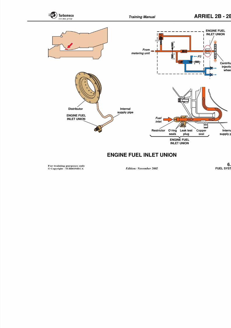
8/13/2019 Arriel_2B-2B1 11-02 En
http://slidepdf.com/reader/full/arriel2b-2b1-11-02-en 210/461
valve
Startelectro-valve
valve
Fuelinjectionsystem
Stopelectro-valve
INITIAL PHASE OF STARTING ACCELERATENGINE STOPPED
P3 P3
Training Manual ARR
MAIN INJECTION SYSTEM
Function Internal supply pipe
8/13/2019 Arriel_2B-2B1 11-02 En
http://slidepdf.com/reader/full/arriel2b-2b1-11-02-en 211/461
The injection system sprays fuel into the combustionchamber to give stable and efficient combustion.
Position
- In the system : downstream of the fuel valve assembly
- On the engine : inside the combustion chamber. Theinjection wheel is mounted between the centrifugalcompressor and the turbine shaft.
Main characteristics
- Type : centrifugal injection
- Radial fuel supply.
Description
The main injection system comprises the fuel inlet union,the internal supply pipe and the centrifugal injectionassembly.
Engine fuel inlet union
Fi d h l i h f f f h
This pipe connects the inlet union to
Centrifugal injection assembly
This assembly consists of a stationarinjection wheel. The distributor is drildeliver the fuel to the wheel. The injecbetween the compressor and the tur
with holes which form the fuel spbetween the distributor and the whpressurised labyrinth seals.
Operation
As the injection wheel is rotating at fuel is centrifuged out through the
sprayed between the two swirl plate
It should be noted that the injection prthe centrifugal force and therefore therequire very high pressures.
The injection wheel fuel chamber is slabyrinth seals. There is a small aichamber. During shut-down the fusystem is purged via the fuel valve a
Training Manual ARR
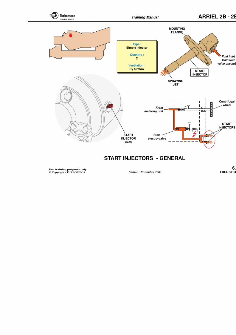
8/13/2019 Arriel_2B-2B1 11-02 En
http://slidepdf.com/reader/full/arriel2b-2b1-11-02-en 212/461
Type :
Centrifugal injection,radial fuel supply
CENTRIFUGAL
INJECTION WHEEL(with spraying jets)
INTERNALSUPPLY PIPE
ENGINE FUEL
INLET UNION
ENGINE FUELINLET UNION
DISTRIBUTORFuel inlet
DISTRIBUTOR
Leak test
plug
Restrictor
Pressurising
valve
CENTRIFUGAL
WHEELFrom metering unit
To stop purge valve
Training Manual ARR
ENGINE FUEL INLET UNION
Function Operation
8/13/2019 Arriel_2B-2B1 11-02 En
http://slidepdf.com/reader/full/arriel2b-2b1-11-02-en 213/461
The union ensures transfer of the fuel from the externalpipe to the internal supply pipe.
Position
- In the system : downstream of the pressurising valve
- On the engine : it is fitted at the lower right front face of the compressor casing.
Description
The device comprises :
- A body with a mounting flange and an internal restrictor
- A leak test plug
- Seals (O'rings and copper seal).
The union ensures the fuel transfer band internal fuel ducts of the main in
The restrictor is used to increase pressure thus to improve the pumpassembly ∆P valve operation.
The leak test plug helps to check the i
union (there should not be any leak)
Training Manual ARR
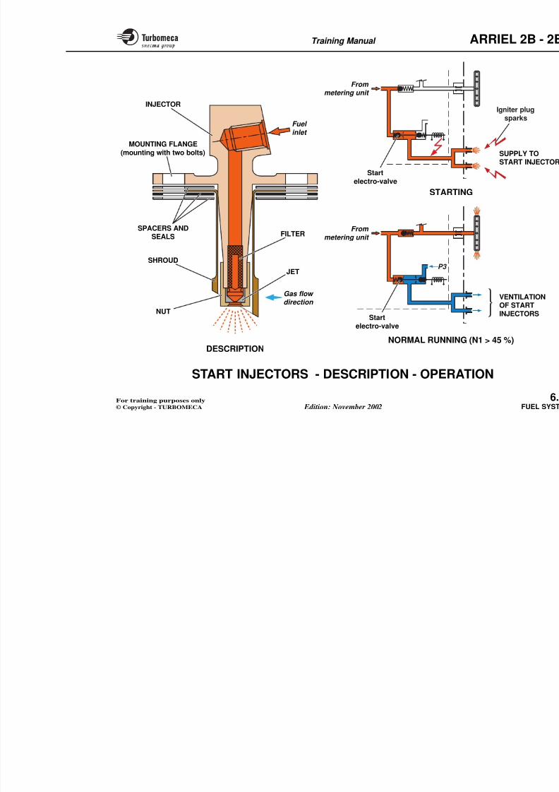
8/13/2019 Arriel_2B-2B1 11-02 En
http://slidepdf.com/reader/full/arriel2b-2b1-11-02-en 214/461
Internalsupply pipe
ENGINE FUELINLET UNION
Distributor
From
metering unit P3
Fuel
inlet
Leak test
plug
Coppe
seal
Restrictor O’ring
seals
Training Manual ARR
START INJECTORS - GENERAL
Function Main components
8/13/2019 Arriel_2B-2B1 11-02 En
http://slidepdf.com/reader/full/arriel2b-2b1-11-02-en 215/461
The two start injectors spray fuel into the combustionchamber during engine starting.
Position
- In the system : downstream of the start electro-valve
- On the engine : on the upper half of the turbine casing at2 o'clock and 10 o'clock
- They penetrate into the mixer unit.
Main characteristics
- Type : simple injector
- Quantity : 2
- Ventilation : by air flow.
- Mounting flange
- Fuel inlet union
- Injector body
- Spraying jet.
Training Manual ARR
MOUNTINGFLANGE
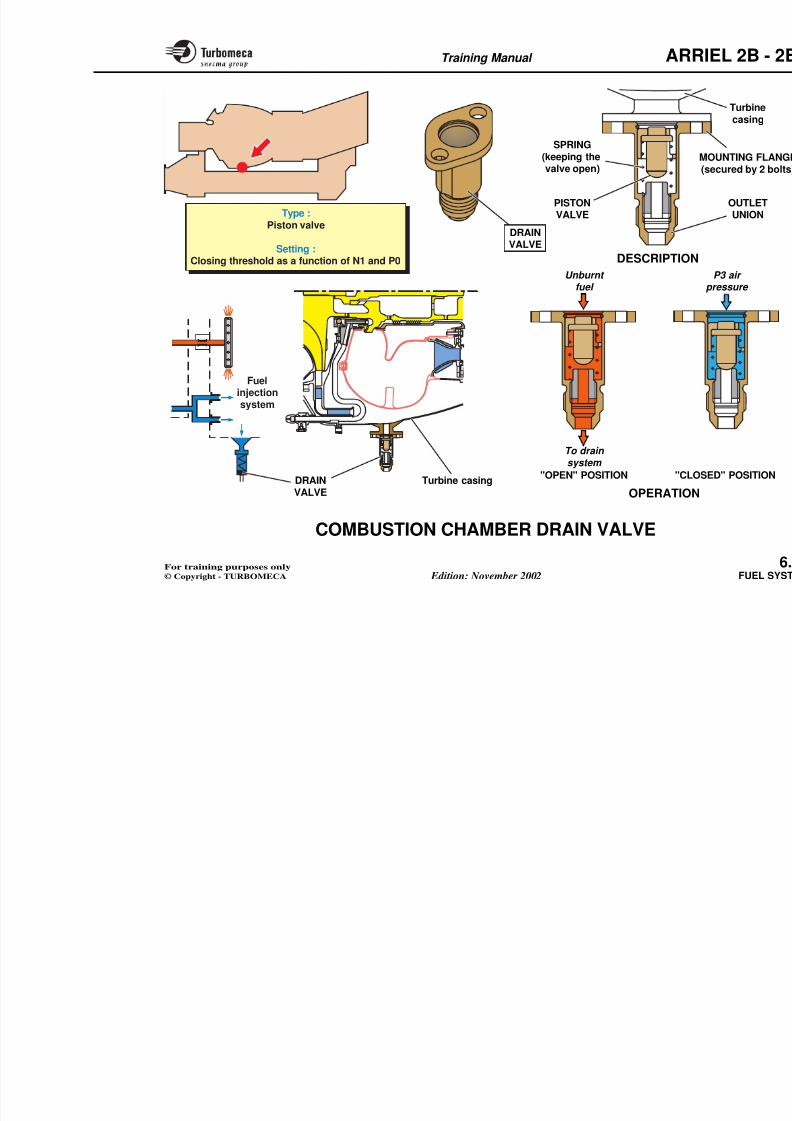
8/13/2019 Arriel_2B-2B1 11-02 En
http://slidepdf.com/reader/full/arriel2b-2b1-11-02-en 216/461
STARTINJECTOR Startelectro-valve
From
metering unit
Type :Simple injector
Quantity :2
Ventilation :By air flow
SPRAYINGJET
STARTINJECTOR
Training Manual ARR
START INJECTORS - DESCRIPTION -
OPERATION
8/13/2019 Arriel_2B-2B1 11-02 En
http://slidepdf.com/reader/full/arriel2b-2b1-11-02-en 217/461
DescriptionThe injectors are mounted on the upper part of the turbinecasing. They penetrate into the combustion chamberthrough holes in the mixer unit.
They are secured by two bolts onto bosses with seals andspacers to prevent leaks and adjust the depth of penetrationinto the combustion chamber.
Injector components
- Injector body
- Fuel inlet (threaded to receive a union)
- Spacers and seals (depth adjustment)
- Mounting flange (secured by 2 bolts)
- Filter
- Nut
- Jet
- Shroud.
Operation
Starting
During starting the injectors are supp
The fuel is atomised and is ignited byigniter plugs. The flame thus produ
sprayed by the centrifugal injection w
Normal running
When the engine reaches self-sustai45 %) the fuel supply to the injector
P3 air is then blown through thecarbonisation of the residual fuel.
It should be noted that ventilation iengine running.
Training Manual ARR
From
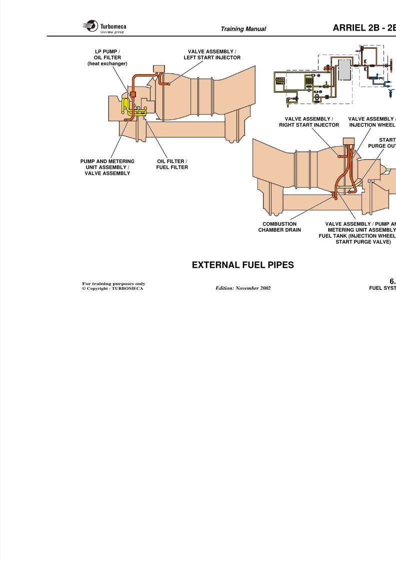
8/13/2019 Arriel_2B-2B1 11-02 En
http://slidepdf.com/reader/full/arriel2b-2b1-11-02-en 218/461
metering unit
From
metering unit
Startelectro-valve
Startelectro-valve
P3
FILTER
JET
Gas flow direction
SPACERS ANDSEALS
SHROUD
NUT
Fuel
inlet
MOUNTING FLANGE(mounting with two bolts)
INJECTOR
STARTING
Training Manual ARR
COMBUSTION CHAMBER DRAIN VALVE
Function Operation

8/13/2019 Arriel_2B-2B1 11-02 En
http://slidepdf.com/reader/full/arriel2b-2b1-11-02-en 219/461
The valve drains overboard any unburnt fuel remaining inthe combustion chamber.
Position
- On the engine : at the bottom of the turbine casing.
Main characteristics
- Type : piston valve
- Setting : Closing threshold as a function of N1 and P0.
Description
The drain valve includes the following components :- A mounting flange (secured by two bolts on a mounting
pad located at the bottom of the turbine casing).
- A piston valve held open by a spring
- An outlet union which connects to the drain system.
The valve has two positions : open a
Open position
When the engine is not running andstart, the valve is held open by the a
Any unburnt fuel in the combustionthrough the valve overboard to theensures that no fuel accumulates in thewhich could cause starting overtemperature).
Closed position
As the engine starts the combustioincreases. This pressure is felt on the
valve which moves down to close th
The valve closes during starting whena given threshold as a function of N
Training Manual ARR
8/13/2019 Arriel_2B-2B1 11-02 En
http://slidepdf.com/reader/full/arriel2b-2b1-11-02-en 220/461
Fuelinjectionsystem
DRAIN
VALVE
SPRING(keeping thevalve open)
PISTONVALVE
M
DESCRIPTION
Unburnt fuel
To drain system
Type :Piston valve
Setting :Closing threshold as a function of N1 and P0
Training Manual ARR
EXTERNAL FUEL PIPES
Function
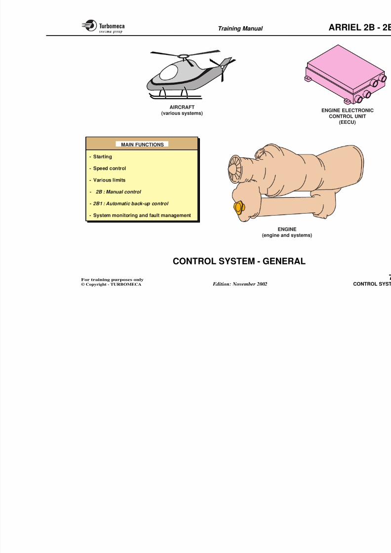
8/13/2019 Arriel_2B-2B1 11-02 En
http://slidepdf.com/reader/full/arriel2b-2b1-11-02-en 221/461
The fuel pipes ensure the circulation of fuel between thecomponents of the system.
Main characteristics
- Type : rigid, stainless steel.
Main pipes
- From LP pump to oil filter (heat exchanger)
- From oil filter to fuel filter
- From pump and metering unit assembly to valve assembly
- From valve assembly to start injectors (x2)
- From valve assembly and pump and metering unitassembly to tank (injection wheel and start purge valve)
- From valve assembly to injection wheel.
Training Manual ARR
LP PUMP /
OIL FILTER(heat exchanger)
VALVE ASSEMBLY /
LEFT START INJECTOR
8/13/2019 Arriel_2B-2B1 11-02 En
http://slidepdf.com/reader/full/arriel2b-2b1-11-02-en 222/461
(heat exchanger)
OIL FILTER /FUEL FILTER
PUMP AND METERINGUNIT ASSEMBLY /
VALVE ASSEMBLY
VALVE ASSEMBLY /RIGHT START INJECTOR
VALVE AS
METERINFUEL TANK (
COMBUSTION
CHAMBER DRAIN
VI
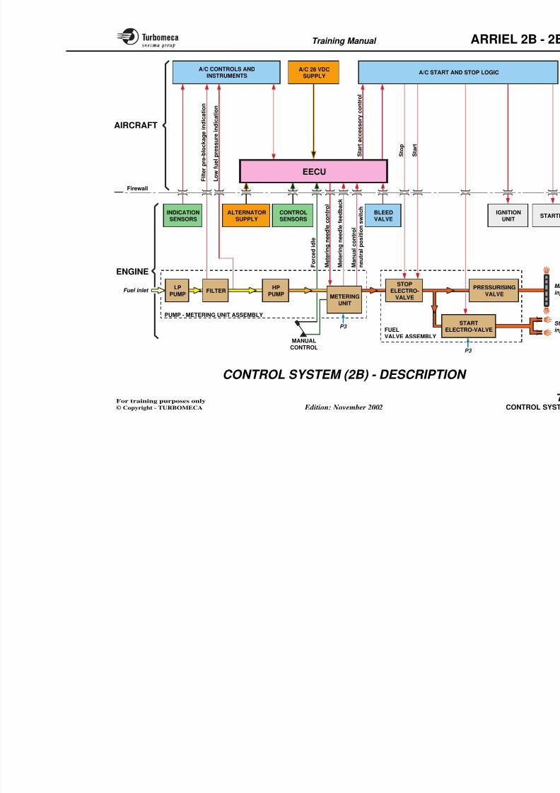
8/13/2019 Arriel_2B-2B1 11-02 En
http://slidepdf.com/reader/full/arriel2b-2b1-11-02-en 223/461
Training Manual ARR
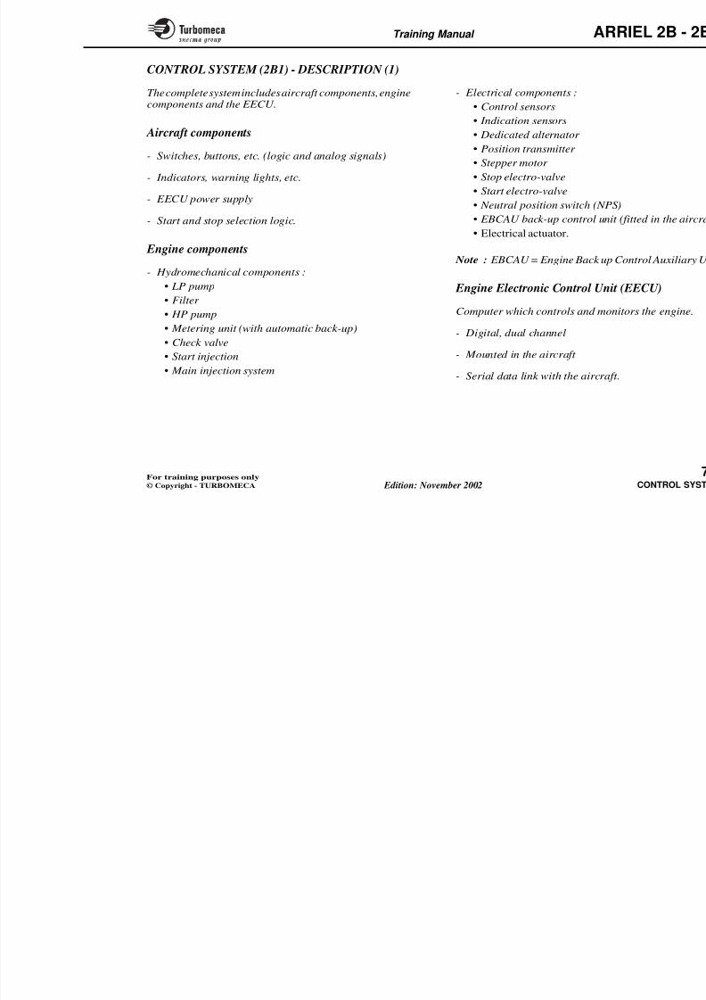
8/13/2019 Arriel_2B-2B1 11-02 En
http://slidepdf.com/reader/full/arriel2b-2b1-11-02-en 224/461
7-CONTROL SYSTEM
- Control system ............................................................... 7
• General ................................................................... 7
• Description .............................................................. 7
• Operation ............................................................... 7
•Indication and monitoring .................................... 7
- Engine Electronic Control Unit (73-21-00) ................. 7
• General .................................................................... 7
•Functional description ........................................... 7
Training Manual ARR
Main components
CONTROL SYSTEM - GENERAL
Functions
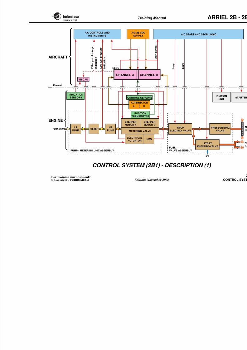
8/13/2019 Arriel_2B-2B1 11-02 En
http://slidepdf.com/reader/full/arriel2b-2b1-11-02-en 225/461
- Engine Electronic Control Unit
- Engine and systems
- Aircraft : various systems (control
The system is designed to adapt the engine to the aircraftpower requirements whilst remaining within defined limits.
The main functions are :
- Starting
- Speed control
- Various limits
- 2B : Manual control
- 2B1 : Automatic back-up control
- System monitoring and fault management.
Main characteristics2B : - Single channel digital electronic control system
- Manual control
2B1 : - Dual channel digital electronic control system
- Automatic back-up control
- Redundant electrical supply (from the aircraft and fromthe engine alternator).
Training Manual ARR
8/13/2019 Arriel_2B-2B1 11-02 En
http://slidepdf.com/reader/full/arriel2b-2b1-11-02-en 226/461
ENGINE EL
CONTR(EE
AIRCRAFT
(various systems)
ENGINE
MAIN FUNCTIONS
- Starting
- Speed control
- Various limits
- 2B : Manual control
- 2B1 : Automatic back-up control
- System monitoring and fault management
Training Manual ARR
CONTROL SYSTEM (2B) - DESCRIPTION
The complete system includes aircraft components, enginecomponents and the EECU.
- Electrical components :
• Control system sensors
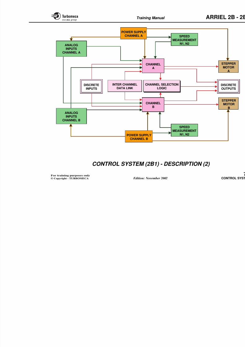
8/13/2019 Arriel_2B-2B1 11-02 En
http://slidepdf.com/reader/full/arriel2b-2b1-11-02-en 227/461
Aircraft components
- Switches, buttons, etc. (logic and analog signals)
- Indicators, warning lights, etc.
- EECU power supply
- Start and stop selection logic.
Engine components
- Hydromechanical components :
• LP pump
• Filter
• HP pump
• Metering unit (with manual control)
• Check valve
• Start injection
• Main injection system
• Indication system sensors• Dedicated alternator
• Position transmitter
• Stepper motor
• Bleed valve position microswit
• Forced idle microswitch
• Stop electro-valve
• Start electro-valve• Neutral position switch.
Engine Electronic Control Unit (
Computer which controls and monit
- Digital
- Mounted in the aircraft
- Serial data link with the aircraft.
Training Manual ARR
A/C CONTROLS ANDINSTRUMENTS
A/C 28 VDCSUPPLY
A/C START AND STOP LOGIC
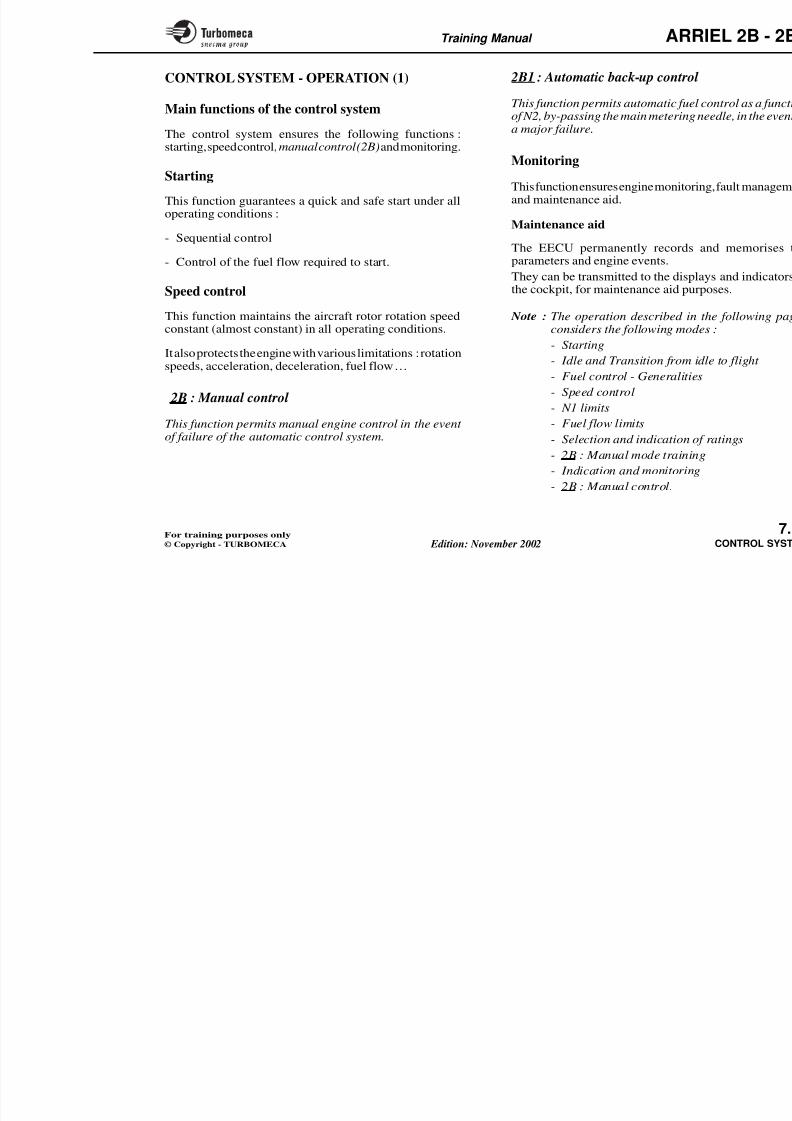
8/13/2019 Arriel_2B-2B1 11-02 En
http://slidepdf.com/reader/full/arriel2b-2b1-11-02-en 228/461
AIRCRAFT
Firewall
LPPUMP
STOPELECTRO-
VALVEFILTER
HPPUMP METERING
UNIT
PRESSUVAL
STARTELECTRO-VALVE
Fuel inlet
ENGINE
FUEL
PUMP - METERING UNIT ASSEMBLY
P3
M e t e r i n g
n e e d l e c o n t r o l
M e t e r i n g
n e e d l e f e e d b a c k
M a n u a l c o n t r o l
n e u t r a l p o s i t i o n s w i t c h
EECU
INDICATIONSENSORS
ALTERNATORSUPPLY
CONTROLSENSORS
BLEEDVALVE
F i l t e
r p r e - b l o c k a g e i n d i c a t i o n
S t a r t a c c e s s o r y c o n t r o l
S t o p
S t a r t
L o w
f u e l p r e s s u r e i n d i c a t i o n
F o r c e d i d l e
Training Manual ARR
CONTROL SYSTEM (2B1) - DESCRIPTION (1)
The complete system includes aircraft components, enginecomponents and the EECU.
- Electrical components :
• Control sensors
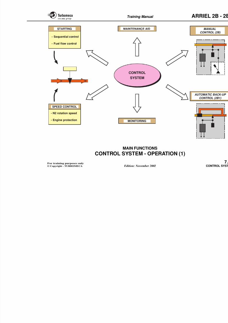
8/13/2019 Arriel_2B-2B1 11-02 En
http://slidepdf.com/reader/full/arriel2b-2b1-11-02-en 229/461
Aircraft components
- Switches, buttons, etc. (logic and analog signals)
- Indicators, warning lights, etc.
- EECU power supply
- Start and stop selection logic.
Engine components
- Hydromechanical components :
• LP pump
• Filter
• HP pump
• Metering unit (with automatic back-up)
• Check valve
• Start injection
• Main injection system
• Indication sensors• Dedicated alternator
• Position transmitter
• Stepper motor
• Stop electro-valve
• Start electro-valve
• Neutral position switch (NPS)
• EBCAU back-up control unit (f
• Electrical actuator.
Note : EBCAU = Engine Back up Co
Engine Electronic Control Unit (
Computer which controls and monit
- Digital, dual channel
- Mounted in the aircraft
- Serial data link with the aircraft.
Training Manual ARR
A/C START AND STOP LOGICA/C 28 VDC
SUPPLYA/C CONTROLS AND
INSTRUMENTS
8/13/2019 Arriel_2B-2B1 11-02 En
http://slidepdf.com/reader/full/arriel2b-2b1-11-02-en 230/461
AIRCRAFT
Firewall
Fuel inlet
ENGINE
INDICATIONSENSORS
S t a r t c o n t r o l
S t o p
S t a r t
EECU
CONTROL SENSORSIG
LPPUMP
STOPELECTRO- VALVE
PRESSVA
FILTERHP
PUMP
NPS
METERING VALVE
STARTELECTRO-VALVE
ELECTRICALACTUATOR
EBCAU
A B
ALTERNATOR
STEPPERMOTOR A
STEPPERMOTOR B
POSITIONTRANSMITTER
F i l t e r p r e - b l o c k a g e
i n d i c a t i o n
L o w f u
e l p r e s s u r e
i n d i c a t i o n
CHANNEL BCHANNEL A
Training Manual ARR
CONTROL SYSTEM (2B1) - DESCRIPTION (2)
The EECU has two independent channels A and B. Bothchannels have the same software.
Channel selection
A channel selector in the EECU will s
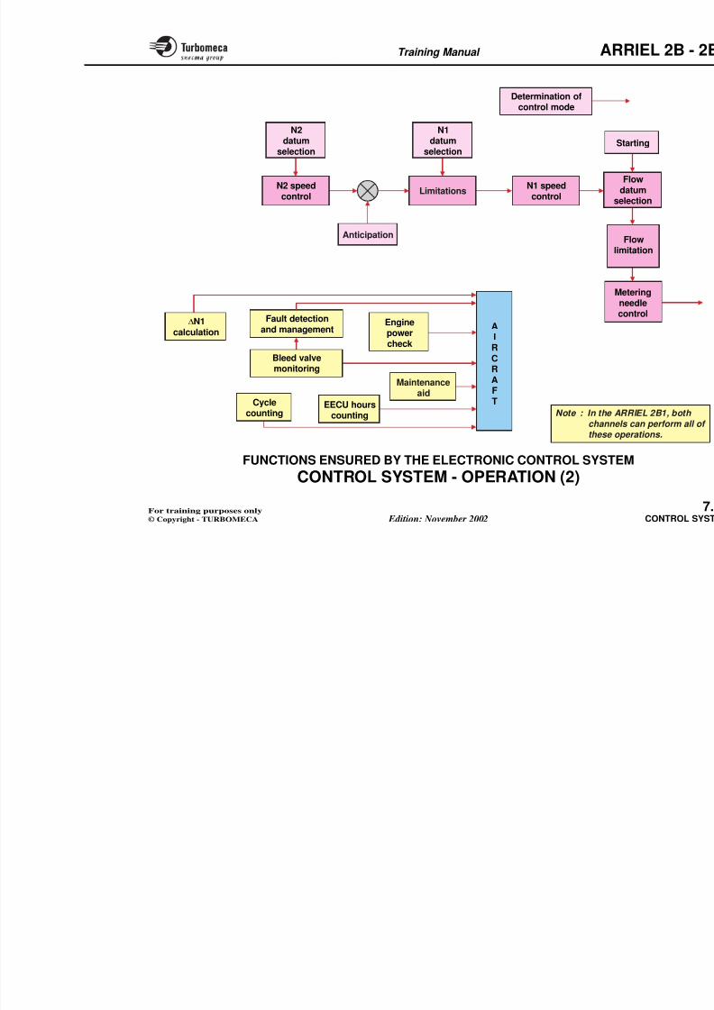
8/13/2019 Arriel_2B-2B1 11-02 En
http://slidepdf.com/reader/full/arriel2b-2b1-11-02-en 231/461
Analog inputs
The two channels receive the following analog inputs : P3,t4.5, resolver position,Tq, N2 trim, P0, t0, collective pitchand conformation resistances Tq and t4.5.
The inputs are shared between the two channels. The N1and N2 inputs are independent for each channel.
There is a data link between the two channels.
This configuration ensures that if all the acquisitions onone channel fail the acquisitions of the other channel aresufficient to control the engine safely.
Discrete inputs and outputs
The discrete inputs are received and shared by the twochannels and the discrete outputs are controlled by theselected channel. The resources of each channel receivetheir power supply from the corresponding channel. Theshared resources receive their power supply from bothchannels.
will control the engine depending on t from the two channels. The normal chthe system changes automatically to
If both channels are unable to controstepper motor is frozen.
Training Manual ARR
POWER SUPPLYCHANNEL A SPEED
MEASUREMENT
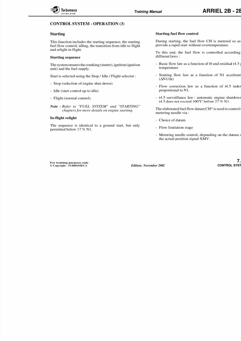
8/13/2019 Arriel_2B-2B1 11-02 En
http://slidepdf.com/reader/full/arriel2b-2b1-11-02-en 232/461
CHANNELA
CHANNEL
B
INTER CHANNELDATA LINK
N1, N2ANALOGINPUTS
CHANNEL A
ANALOGINPUTS
CHANNEL B
DISCRETEINPUTS
CHANNEL SELECTIONLOGIC
SPEEDMEASUREMENT
N1, N2POWER SUPPLYCHANNEL B
Training Manual ARR
CONTROL SYSTEM - OPERATION (1)
Main functions of the control system
2B1 : Automatic back-up control
This function permits automatic fuel of N2, by-passing the main metering na major failure.
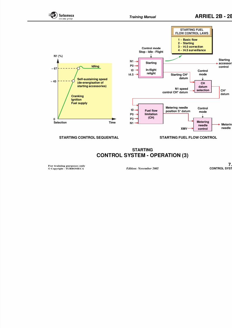
8/13/2019 Arriel_2B-2B1 11-02 En
http://slidepdf.com/reader/full/arriel2b-2b1-11-02-en 233/461
The control system ensures the following functions :starting, speed control,manual control (2B) and monitoring.
Starting
This function guarantees a quick and safe start under alloperating conditions :
- Sequential control- Control of the fuel flow required to start.
Speed control
This function maintains the aircraft rotor rotation speedconstant (almost constant) in all operating conditions.
It also protects the engine with various limitations : rotationspeeds, acceleration, deceleration, fuel flow…
2B : Manual control
This function permits manual engine control in the event of failure of the automatic control system.
Monitoring
This function ensures engine monitorinand maintenance aid.
Maintenance aid
The EECU permanently records parameters and engine events.
They can be transmitted to the displathe cockpit, for maintenance aid pur
Note : The operation described in considers the following mode
- Starting- Idle and Transition from id
- Fuel control - Generalities
- Speed control
- N1 limits
- Fuel flow limits
- Selection and indication of
- 2B : Manual mode trainingIndication and monitoring
Training Manual ARR
STARTING MAINTENANCE AID
C
- Sequential control
8/13/2019 Arriel_2B-2B1 11-02 En
http://slidepdf.com/reader/full/arriel2b-2b1-11-02-en 234/461
CONTROL
SYSTEM
MONITORING
- Fuel flow control
SPEED CONTROL
- N2 rotation speed
- Engine protection
AUTO
CO
Training Manual ARR
CONTROL SYSTEM - OPERATION (2)
Functions ensured by the electronic control
system
Monitoring
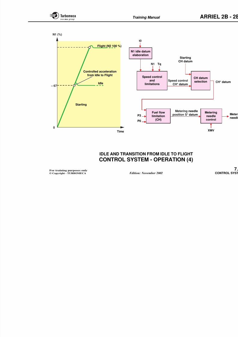
8/13/2019 Arriel_2B-2B1 11-02 En
http://slidepdf.com/reader/full/arriel2b-2b1-11-02-en 235/461
This part mentions in a general way the main functionalelectronic blocks.
Note : In the ARRIEL 2B1, both channels can perform allof these operations.
Control mode determination
Starting
N2 datum selection
N2 speed control
Anticipation
N1 datum selection
Limitations (N1, torque…)
N1 speed control
Flow datum selection
Flow limitation
M t i dl t l
- Engine power check
- ∆N1 indication calculation
- Cycle counting
- EECU hours counting
- Definition of serial messages
- Fault detection and management
- Data bus interfaces with the aircra
- Bleed valve monitoring
- Maintenance aid.
Training Manual ARR
Determination ofcontrol mode
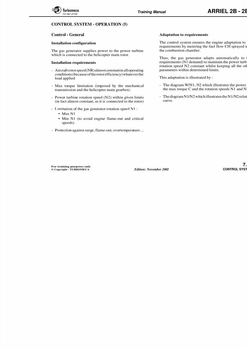
8/13/2019 Arriel_2B-2B1 11-02 En
http://slidepdf.com/reader/full/arriel2b-2b1-11-02-en 236/461
N1datum
selection
N2datum
selection
Anticipation
N2 speedcontrol
LimitationsN1 speedcontrol
∆N1calculation
Fault detectionand management
Bleed valvemonitoring
Cycle
counting
EECU hours
counting
Maintenanceaid
Enginepowercheck
AIRCRAFT
Fldat
sele
Fllimit
Metenee
con
Star
Note : In the ARRchannels c
Training Manual ARR
CONTROL SYSTEM - OPERATION (3)
Starting
Thi f i i l d h i h i
Starting fuel flow control
D i i h f l fl CH
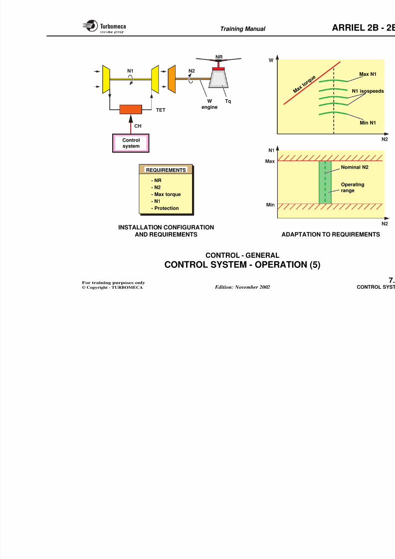
8/13/2019 Arriel_2B-2B1 11-02 En
http://slidepdf.com/reader/full/arriel2b-2b1-11-02-en 237/461
This function includes the starting sequence, the startingfuel flow control, idling, the transition from idle to flightand relight in flight.
Starting sequence
The system ensures the cranking (starter), ignition (ignitionunit) and the fuel supply.
Start is selected using the Stop / Idle / Flight selector :
- Stop (selection of engine shut-down)
- Idle (start control up to idle)
- Flight (normal control).
Note : Refer to "FUEL SYSTEM" and "STARTING" chapters for more details on engine starting.
In-flight relight
The sequence is identical to a ground start, but onlypermitted below 17 % N1.
During starting, the fuel flow CH provide a rapid start without overtem
To this end, the fuel flow is contdifferent laws :
- Basic flow law as a function of t0 temperature
- Starting flow law as a function (∆N1/ ∆t)
- Flow correction law as a functiproportional to N1.
- t4.5 surveillance law : automatic t4.5 does not exceed 100°C before
The elaborated fuel flow datum CH* metering needle via :
- Choice of datum
- Flow limitation stage
- Metering needle control, dependin
the actual position signal XMV.
Training Manual ARR
STARTING FUELFLOW CONTROL LAW
1 B i fl
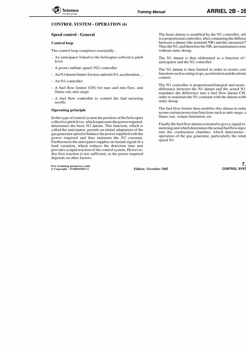
8/13/2019 Arriel_2B-2B1 11-02 En
http://slidepdf.com/reader/full/arriel2b-2b1-11-02-en 238/461
STARTING FUEL FLOW CO
Contrmod
N1 speedcontrol CH* datum
Control modeStop - Idle - Flight
CHdatum
selecti
Meterineedcontr
Idling
N1 (%)
0
≈ 67
TimeSelection
CrankingIgnition
Fuel supply
Self-sustaining speed(de-energisation ofstarting accessories)
STARTING CONTROL SEQUENTIAL
t4.5
P0
t0
N1
N1
XMV
P0
P3
t0Contrmod
Metering needleposition S* datumFuel flow
limitation(CH)
≈ 45
Starting
In-flightrelight Starting CH*
datum
1 - Basic flow2 - Starting3 - t4.5 correction4 - t4.5 surveillance
Training Manual ARR
CONTROL SYSTEM - OPERATION (4)
Starting (continued)
Idl
Control functions
El b ti f th N1 idl d t
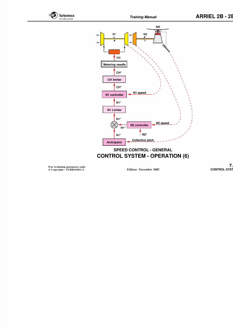
8/13/2019 Arriel_2B-2B1 11-02 En
http://slidepdf.com/reader/full/arriel2b-2b1-11-02-en 239/461
Idle
When starting is completed, the rotation speed stabilises atidle which is 67 - 68 % (function of t0).
Transition from idle to flight
This is effected by moving the selector from idle to flight.
This transition is prohibited until a given increase of N2has been registered.
During the transition, the torque and N2 acceleration arelimited.
The transition is completed when the system enters intonominal speed control. The control loop comprises the N2
control which elaborates an N1 datum, and the N1 controlwhich elaborates a fuel flow datum CH*.
- Elaboration of the N1 idle datum a
- Transition control
- Speed control (N2, N1, limitations
- Selection of fuel flow datum CH*
- Flow control
- Metering needle control.
Training Manual ARR
N1 (%)
t0
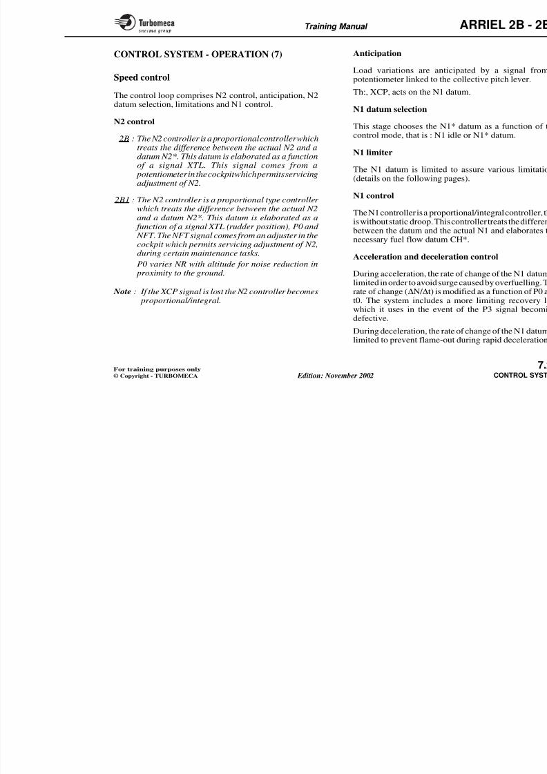
8/13/2019 Arriel_2B-2B1 11-02 En
http://slidepdf.com/reader/full/arriel2b-2b1-11-02-en 240/461
Fuel flow
limitation(CH)
Speed control
CH* datum
CH datum
selection
Starting
CH datum
Flight (N2 100 %)
Idle
Starting
Time
Controlled acceleration
from Idle to Flight
Mete
neecon
Metering needleposition S* datum
≈ 67
0
t0
N1 Tq
P3
P0
Speed control
andlimitations
N1 idle datum
elaboration
XM
Training Manual ARR
CONTROL SYSTEM - OPERATION (5)
Control - General
I st ll ti fig ti
Adaptation to requirements
Th t l t m th i
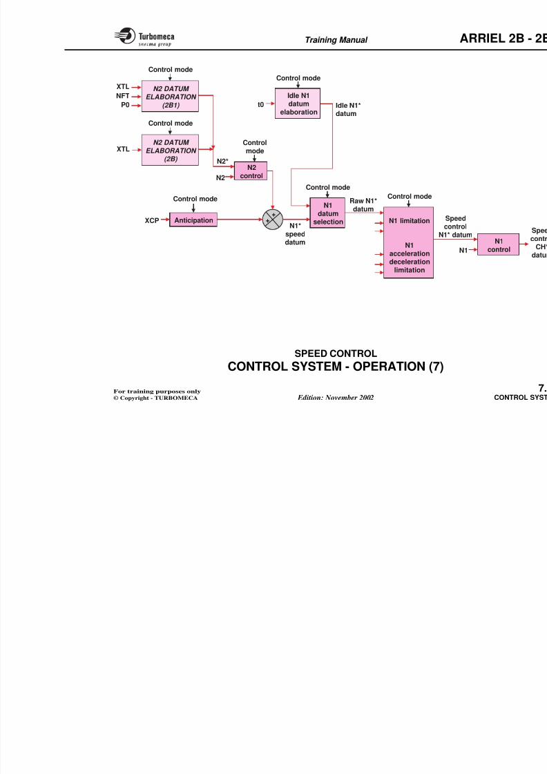
8/13/2019 Arriel_2B-2B1 11-02 En
http://slidepdf.com/reader/full/arriel2b-2b1-11-02-en 241/461
Installation configuration
The gas generator supplies power to the power turbinewhich is connected to the helicopter main rotor.
Installation requirements
- Aircraft rotor speed (NR) almost constant in all operatingconditions (because of the rotor efficiency) whatever theload applied
- Max torque limitation (imposed by the mechanicaltransmission and the helicopter main gearbox)
- Power turbine rotation speed (N2) within given limits(in fact almost constant, as it is connected to the rotor)
- Limitation of the gas generator rotation speed N1 :• Max N1
• Min N1 (to avoid engine flame-out and criticalspeeds)
- Protection against surge, flame-out, overtemperature ...
The control system ensures the engirequirements by metering the fuel flthe combustion chamber.
Thus, the gas generator adapts aurequirements (N1 demand) to maintarotation speed N2 constant whilst kparameters within determined limits
This adaptation is illustrated by :
- The diagram W/N1, N2 which illuthe max torque C and the rotation
- The diagram N1/N2 which illustratcurve.
Training Manual ARR
N1
NRW
N2
8/13/2019 Arriel_2B-2B1 11-02 En
http://slidepdf.com/reader/full/arriel2b-2b1-11-02-en 242/461
N1
CH
N1
Max
Min
M a x t
o r q u
e
TET
N2
TqW
engine
Controlsystem
INSTALLATION CONFIGURATIONAND REQUIREMENTS
Nom
Operang
ADAPTATION TO REQU
REQUIREMENTS
- NR
- N2
- Max torque
- N1
- Protection
Training Manual ARR
CONTROL SYSTEM - OPERATION (6)
Speed control - General
Control loop
The basic datum is modified by the Nis a proportional controller, after com
between a datum (the nominal NR) a
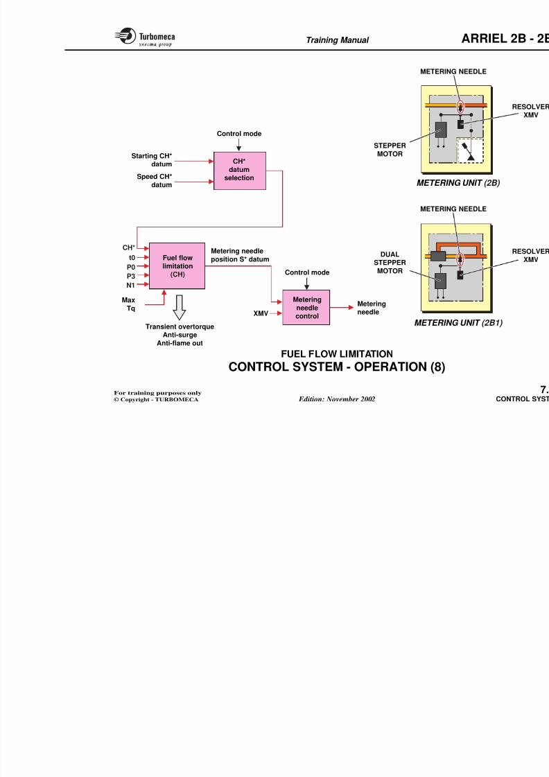
8/13/2019 Arriel_2B-2B1 11-02 En
http://slidepdf.com/reader/full/arriel2b-2b1-11-02-en 243/461
Control loop
The control loop comprises essentially :
- An anticipator linked to the helicopter collective pitchlever
- A power turbine speed (N2) controller
- An N1 datum limiter for max and min N1, acceleration…
- An N1 controller
- A fuel flow limiter (CH) for max and min flow, antiflame-out, anti-surge
- A fuel flow controller to control the fuel meteringneedle.
Operating principle
In this type of control system the position of the helicoptercollective pitch lever, which represents the power required,determines the basic N1 datum. This function, which iscalled the anticipator, permits an initial adaptation of thegas generator speed to balance the power supplied with thepower required and thus maintain the N2 constant.
Furthermore the anticipator supplies an instant signal of aload variation which reduces the detection time and
between a datum (the nominal NR) aThus the N2, and therefore the NR, arewithout static droop.
The N1 datum is thus elaborated aanticipator and the N2 controller.
The N1 datum is then limited in ordfunctions such as rating stops, acceleracontrol.
The N1 controller is proportional/indifference between the N1 datum atranslates the difference into a fuel order to maintain the N1 constant wistatic droop.
The fuel flow limiter then modifies thassure certain protection functions suflame-out, torque limitation, etc.
Finally the fuel flow datum is treated metering unit which determines the actinto the combustion chamber, whoperation of the gas generator, partspeed N1.
Training Manual ARR
N1 N2
NR
8/13/2019 Arriel_2B-2B1 11-02 En
http://slidepdf.com/reader/full/arriel2b-2b1-11-02-en 244/461
CH
CH*
N1*
N1*
N1*
N1*
CH*
N1 speed
N2 speedN2 controller
N1 controller
N2*
N1 Limiter
CH limiter
Metering needle
Training Manual ARR
CONTROL SYSTEM - OPERATION (7)
Speed control
The control loop comprises N2 control anticipation N2
Anticipation
Load variations are anticipated bpotentiometer linked to the collectiv
Th: XCP acts on the N1 datum
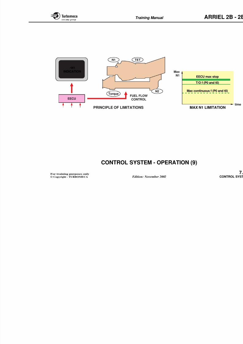
8/13/2019 Arriel_2B-2B1 11-02 En
http://slidepdf.com/reader/full/arriel2b-2b1-11-02-en 245/461
The control loop comprises N2 control, anticipation, N2datum selection, limitations and N1 control.
N2 control
2B : The N2 controller is a proportional controller whichtreats the difference between the actual N2 and adatum N2*. This datum is elaborated as a function
of a signal XTL. This signal comes from a potentiometer in the cockpit which permits servicingadjustment of N2.
2B1 : The N2 controller is a proportional type controller which treats the difference between the actual N2and a datum N2*. This datum is elaborated as a
function of a signal XTL (rudder position), P0 and NFT. The NFT signal comes from an adjuster in the
cockpit which permits servicing adjustment of N2,during certain maintenance tasks.
P0 varies NR with altitude for noise reduction in proximity to the ground.
Note : If the XCP signal is lost the N2 controller becomes proportional/integral.
Th:, XCP, acts on the N1 datum.
N1 datum selection
This stage chooses the N1* datum control mode, that is : N1 idle or N1
N1 limiter
The N1 datum is limited to assure(details on the following pages).
N1 control
The N1 controller is a proportional/inis without static droop. This controllebetween the datum and the actual N
necessary fuel flow datum CH*.
Acceleration and deceleration con
During acceleration, the rate of changlimited in order to avoid surge causedrate of change (∆N/ ∆t) is modified ast0. The system includes a more limwhich it uses in the event of the P
defective.
Training Manual ARR
Control mode
Control mode
Idle N1
XTL
NFT
N2 DATUM
ELABORATION
8/13/2019 Arriel_2B-2B1 11-02 En
http://slidepdf.com/reader/full/arriel2b-2b1-11-02-en 246/461
++
Control mode
Controlmode
Idle N1datum
elaboration
Control mode
N1 limitation
N1accelerationdeceleration
limitation
Control mode
Speedcontrol
N1* datum
Raw N1*datum
Idle N1*datum
XCP
N2
t0
Anticipation
NFTP0
N1
ELABORATION (2B1)
N2 DATUM
ELABORATION (2B)
XTL
N1datum
selection
N2control
N1*speed
datum
Control mode
N2*
Training Manual ARR
CONTROL SYSTEM - OPERATION (8)
Fuel flow limitation
The system has several fuel flow limitations to control :
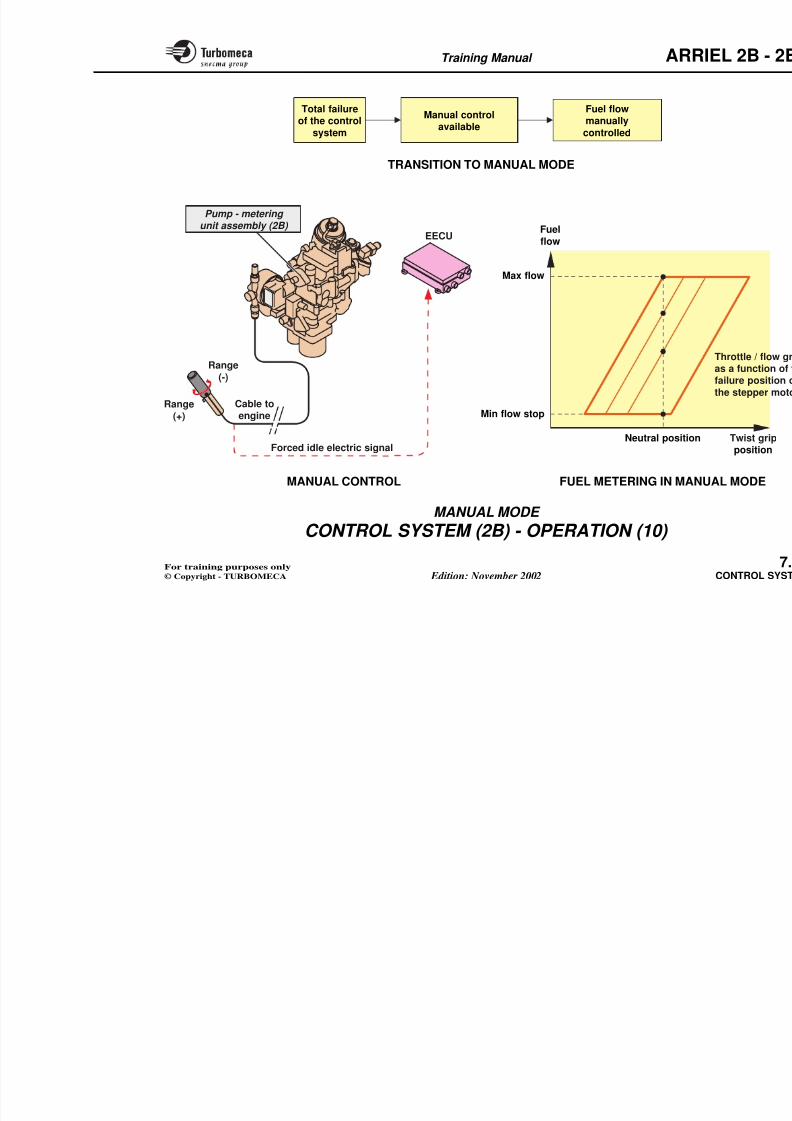
8/13/2019 Arriel_2B-2B1 11-02 En
http://slidepdf.com/reader/full/arriel2b-2b1-11-02-en 247/461
The system has several fuel flow limitations to control :
- Transient overtorque of the power turbine shaft : maxflow limitation signal as a function of a constant
- Surge : max flow limitation as a function of N1, t0, P3and P0 with back-up law in the event of loss of t0 or P0signals
- Flame out : min flow limitation as a function of N1, t0,and P0, with back-up laws in the event of loss of t0 or P0signals.
The fuel flow datum CH* coming from the speed controlloop passes first through a datum selection stage whichmakes the choice between starting CH* and speed controlCH*. The choice depends on the control mode, that is the
present state of control. The output from the selector ispassed to a flow limiter which treats the flow datum as afunction of t0, P0 and P3 to assure the limits. It elaboratesa metering needle position datum which is transmitted tothe metering needle control stage. This control stagereceives a signal of metering needle position XMV andelaborates a control signal for the stepper motor whichpositions the metering needle.
Training Manual ARR
METERING NEEDLE
8/13/2019 Arriel_2B-2B1 11-02 En
http://slidepdf.com/reader/full/arriel2b-2b1-11-02-en 248/461
Transient overtorque
CH*
Starting CH*
datum
Control mode
Control mode
Metering needle
position S* datum
Speed CH*
datum
CH*
datumselection
Fuel flowlimitation
(CH)
XMV
METERING UNIT (2
METERING UNIT (
DUALSTEPPER
MOTOR
STEPPER
MOTOR
P0
P3
t0
N1
Max
Tq
Metering
needle
control
METERING NEEDLE
Meteringneedle
Training Manual ARR
CONTROL SYSTEM - OPERATION (9)
Principle of limitations
Theprincipleoflimitations isbasedononelimitparameter :
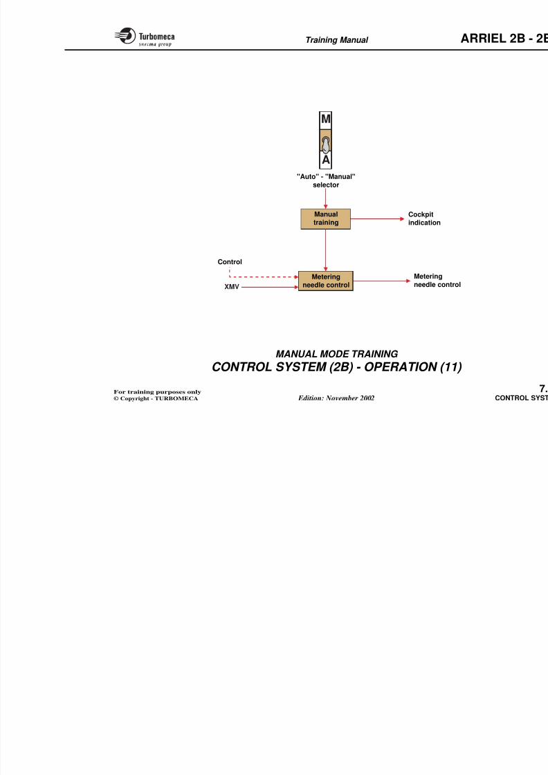
8/13/2019 Arriel_2B-2B1 11-02 En
http://slidepdf.com/reader/full/arriel2b-2b1-11-02-en 249/461
The principle of limitations is based on one limit parameter :the gas generator rotation speed (N1 or Ng).
This speed is therefore the essential piloting parameter.
The other parameters (TET, N2, torque) are kept withingiven limits by the control system.
Max N1 limitation
The maximum N1 is limited automatically, in the followingmanner :
There is no automatic limitation of the take-off ratingwhich is controlled by the pilot. However a stop preventsany exceedance of the max N1.
If the sand filter is active, the EECU derates the N1 limits;the EECU also takes into account the sand filter activesignal for the power check calculation.
Max continuous power is also controlled by the pilot.
Torque limitation
The pilot also controls the max torque applied to the main
gearbox, however as a safety measure the EECU elaborates
Training Manual ARR
8/13/2019 Arriel_2B-2B1 11-02 En
http://slidepdf.com/reader/full/arriel2b-2b1-11-02-en 250/461
Max
N1
Max continuous f (P
T/O f (P0 and
EECU max st
MAX N1 LIMITAPRINCIPLE OF LIMITATIONS
∆N1INDICATION
FUEL FLOWCONTROL
Torque
TETN1
N2
EECU
Training Manual ARR
CONTROL SYSTEM (2B) - OPERATION (10)
Manual mode
This mode permits manual control of the engine in thef l f il f h l
Fuel metering in manual mode
Themanualcontrolhasarangebetweflow
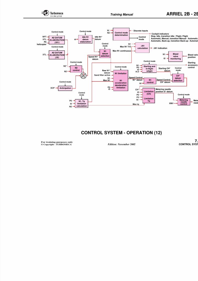
8/13/2019 Arriel_2B-2B1 11-02 En
http://slidepdf.com/reader/full/arriel2b-2b1-11-02-en 251/461
This mode permits manual control of the engine in theevent of complete failure of the control system.
Manual reversion
If the electronic control fails the system is automatically inmanual control. In this mode the fuel flow will only alter if the manual control is moved.
Manual control
The twist grip in the cockpit is connected by a mechanicallinkage to the pump and metering unit assembly.
It has a neutral position, automatic flow control ; a flowincrease range (the plus range), and a flow reductionrange (the minus range).
For more details refer to "FUEL SYSTEM".
Note : The aircraft electrical power should be switched on before moving the twist grip.
The manual control has a range betwe flow.
It allows :
- Engine acceleration without surge power to 95 % of T/O power in lessengine deceleration without flame
- The engine to be reduced to idle bthe twist grip.
Note 1 : It is possible to return toanytime, however it is rec
from a stable condition.
Note 2 : The 2B1 version system is twist grip. The sole purposautorotation training via th
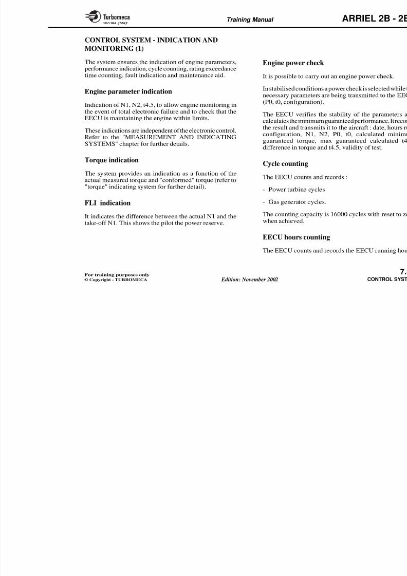
8/13/2019 Arriel_2B-2B1 11-02 En
http://slidepdf.com/reader/full/arriel2b-2b1-11-02-en 252/461
Training Manual ARR
CONTROL SYSTEM (2B) - OPERATION (11)
Manual mode training
The system is designed to allow training in manual modeby simulating a complete failure of the electronic control
8/13/2019 Arriel_2B-2B1 11-02 En
http://slidepdf.com/reader/full/arriel2b-2b1-11-02-en 253/461
The system is designed to allow training in manual modeby simulating a complete failure of the electronic controlsystem by freezing the stepper motor.
The mode is selected using a manual/automatic selector and an indicator gives the status of the system.
The system can be returned to automatic at any time.
Note 1 : Manual control is carried out by displacing thetwist grip out of the neutral position (flight
position). Refer to the "manual control function" p. 7.28 and to the chapter "FUEL SYSTEM" for details.
Note 2 : The above procedure does not apply to the 2B1version. The "Auto" / "Manual" selector is onlyused for periodic maintenance testing of theautomatic back-up control system.
Training Manual ARR
8/13/2019 Arriel_2B-2B1 11-02 En
http://slidepdf.com/reader/full/arriel2b-2b1-11-02-en 254/461
A
M
Manualtraining
"Auto" - "Manual"
selector
Meteringneedle control
Cockpitindication
Metering
needle control
Control
XMV
Training Manual ARR
CONTROL SYSTEM - OPERATION (12)
Operating principle
In this type of control system the position of the helicoptercollective pitch lever, which represents the power required,
The N1 controller is proportional/indifference between the N1 datum a
translates the difference into a fuelorder to maintain the N1 constant wit
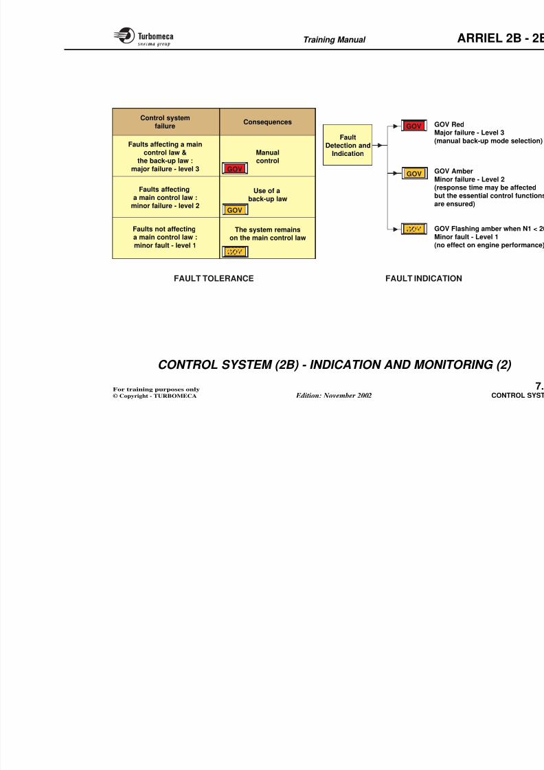
8/13/2019 Arriel_2B-2B1 11-02 En
http://slidepdf.com/reader/full/arriel2b-2b1-11-02-en 255/461
collective pitch lever, which represents the power required,determines the basic N1 datum. This function, which iscalled the anticipator, permits an initial adaptation of thegas genetator speed to balance the power supplied with thepower required and thus maintain the N2 constant.Furthermore the anticipator supplies an instant signal to aload variation, which reduces the detection time andprovides a rapid reaction: However the first reaction is not
sufficient, as the power required depends on other factors.
The basic datum is modified by the N2 controller, whichis a proportional controller, after comparing the differencebetween a datum (the nominal NR) and the measured N2.Thus the N2, and therefore the NR, are maintained constantwithout static droop.
The N1 is thus elaborated as a function of the anticipatorand the N2 controller.
The N1 datum is then limited in order to assure certainfunctions such as rating stops, acceleration and decelerationcontrol.
order to maintain the N1 constant witstatic droop.
The fuel flow limiter then modifies thassure certain protection functions suflame-out, torque limiting, etc.
Finally the fuel flow datum is treated
metering unit which determines the actinto the combustion chamber, whoperation of the gas generator, partspeed N1.
Training Manual ARR
Control mode Control mode N1
NFTN2 DATUM
Discrete inputs
Control Stop, Idle, transition Idle /Cockpit indicators
N2
Idle N1 Idle N1*
Control mode
determination
8/13/2019 Arriel_2B-2B1 11-02 En
http://slidepdf.com/reader/full/arriel2b-2b1-11-02-en 256/461
Control mode
Control mode
++
XCP Anticipation
N2control
N2
XTLN2 DATUM
ELABORATION (2B)
XTLN2 DATUM
ELABORATION (2B1)
Speed N1*datum
N1datum
selection
Control
mode
Controlmode Automatic, Manual, transi
Automatic, Back-up, trans
Control mode
t0
Idle N1datum
elaboration
d edatum
Control
mode
Control mode
P0
t0
N2
N1, Tqlimitation
calculation
N1
Sand filter active
P0t0
N1 limitation
N1accelerationdeceleration
limitation
Max N1
Raw N1*datum
∆N1calculation ∆N1 indication
Max N1 T/O
Max N1 continuous
N1
N1
Speed ControlN1* datum
P0t0
t4.5
Control mode
Starting andin-flightrelight
se
P0
P3
Limitation(CH)
LimitationTq
t0
N1
XMV
Starting CH*datum
N1
Speed ControlCH* datum
CH* Metering needleposition S* datum
Max tq
N1control
N2*
N1
t0
Bleva
moni
P0helicopter
Training Manual ARR
CONTROL SYSTEM - INDICATION AND
MONITORING (1)
The system ensures the indication of engine parameters,performance indication, cycle counting, rating exceedancetime counting, fault indication and maintenance aid.
Engine power check
It is possible to carry out an engine p
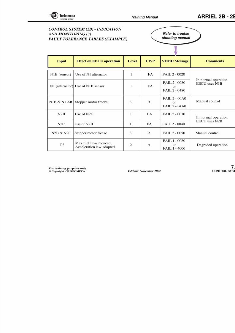
8/13/2019 Arriel_2B-2B1 11-02 En
http://slidepdf.com/reader/full/arriel2b-2b1-11-02-en 257/461
g,
Engine parameter indication
Indication of N1, N2, t4.5, to allow engine monitoring inthe event of total electronic failure and to check that theEECU is maintaining the engine within limits.
These indications are independent of the electronic control.Refer to the "MEASUREMENT AND INDICATINGSYSTEMS" chapter for further details.
Torque indication
The system provides an indication as a function of the
actual measured torque and "conformed" torque (refer to"torque" indicating system for further detail).
FLI indication
It indicates the difference between the actual N1 and thetake-off N1. This shows the pilot the power reserve.
It is possible to carry out an engine p
In stabilised conditions a power checknecessary parameters are being trans(P0, t0, configuration).
The EECU verifies the stability of calculates the minimum guaranteed pe
the result and transmits it to the aircrconfiguration, N1, N2, P0, t0, cguaranteed torque, max guarantedifference in torque and t4.5, validit
Cycle counting
The EECU counts and records :
- Power turbine cycles
- Gas generator cycles.
The counting capacity is 16000 cyclwhen achieved.
EECU hours counting
Training Manual ARR
N2SPEED
N1SPEED
INDICATION Torqueconformation
Torqucalcula
Torque
TORQUE IND
8/13/2019 Arriel_2B-2B1 11-02 En
http://slidepdf.com/reader/full/arriel2b-2b1-11-02-en 258/461
Max N1 take-off
P0
FLIcalcula
t0
N1
SPEEDINDICATION
ENGINE PARAMETER INDICATION(independent from the control system)
FLI INDIC
TORQUE IND
t4.5 GASTEMPERATURE
INDICATION
N2
EECUhours
counting
N1Tq
t4.5
t0
Enginepowercheck
N2
P0 helicopter
N1Cycle
counting
Maintenanceaid
Data
exchan
with air
Faultdetection and
indication
Training Manual ARR
CONTROL SYSTEM (2B) - INDICATION AND
MONITORING (2)
Fault tolerance, Indication and Management
Fault tolerance
Fault indication
There are three levels of indication :
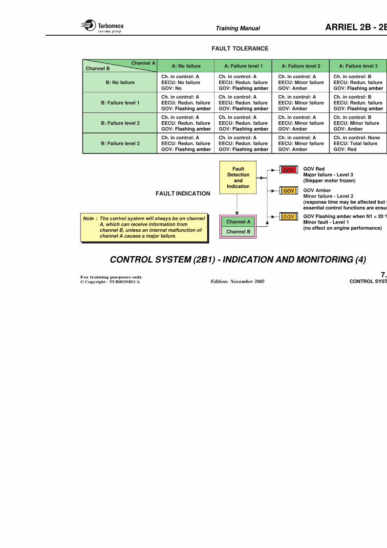
8/13/2019 Arriel_2B-2B1 11-02 En
http://slidepdf.com/reader/full/arriel2b-2b1-11-02-en 259/461
Fault tolerance
If a fault affects a nominal law the system uses a back-uplaw. The essential functions (N1 and N2 control,acceleration and deceleration control) remain ensured.
In the event of a fault affecting a main law and theback-up law the system declares itself unable to control
the engine and the engine must be controlled manually.
f
- Level 3 - Major failure : man
- Level 2 - Minor failure : resaffected but the essenare ensured
- Level 1 - Minor fault : loss ofeffect on engine perf
Two lights provide the fault indicatiGOV (Amber)
- A GOV (Red) indicates a total fasystem
- A GOV (Amber) indicates degradcontrol system. This light also indic
flashing during engine starting, idshut-down (N1 < 20 %).
Training Manual ARR
8/13/2019 Arriel_2B-2B1 11-02 En
http://slidepdf.com/reader/full/arriel2b-2b1-11-02-en 260/461
GOV
GOV
FAULT TOLERANCE
GOV
GOV
GOV
GOV
Control systemfailure
Consequences
Faults affecting
a main control law :minor failure - level 2
Use of aback-up law
Faults affecting a main
control law &the back-up law :
major failure - level 3
Manualcontrol
Faults not affectinga main control law :
minor fault - level 1
The system remainson the main control law
GOV RedMajor failure -
(manual back-uFault
Detection andIndication
GOV AmberMinor failure - (response timebut the essenti
are ensured)
GOV Flashing
Minor fault - Le
(no effect on e
FAULT INDICATION
Training Manual ARR
CONTROL SYSTEM (2B) - INDICATION AND
MONITORING (3)
Fault management
For each input signal, the EECU has a set of criteria with
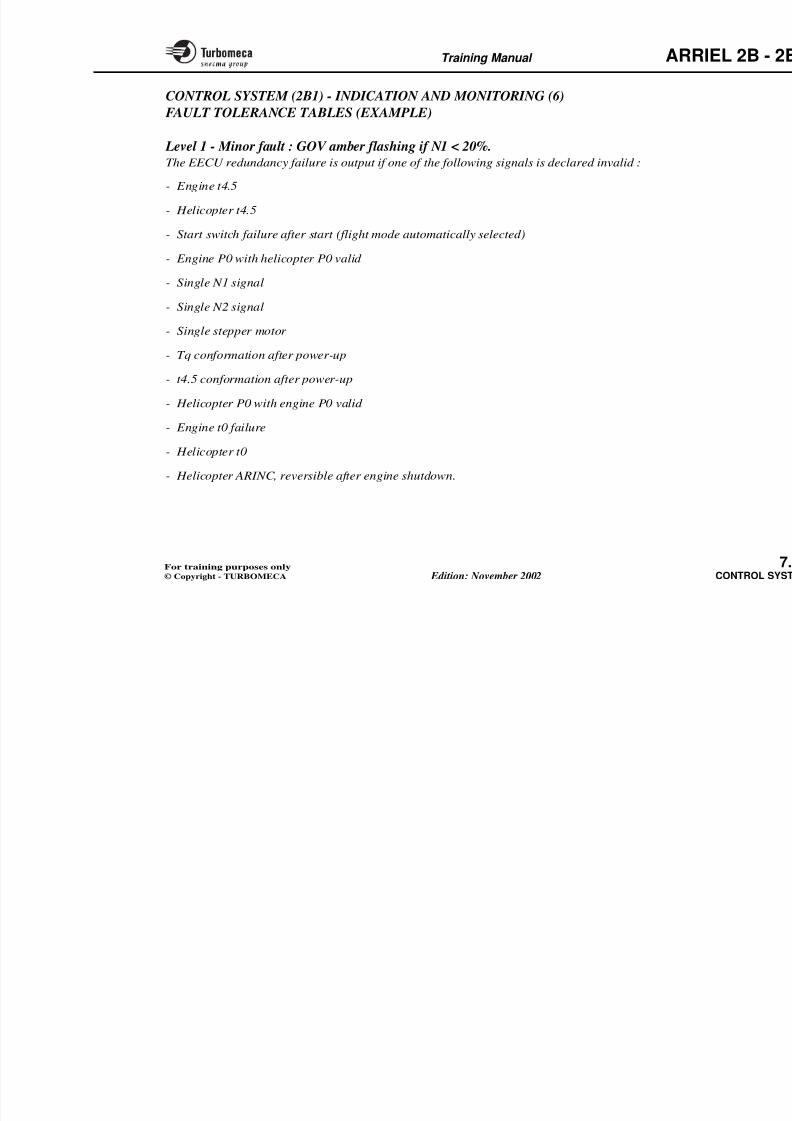
8/13/2019 Arriel_2B-2B1 11-02 En
http://slidepdf.com/reader/full/arriel2b-2b1-11-02-en 261/461
p g , fwhich it can decide if the signal is valid. The tables on the
following pages show the logic used by the EECU in theevent of an invalid signal. They also show the associated
fault level, the CWP indication and the VEMD indicationwhere applicable.
Note 1 : CWP : Central Warning Panel
VEMD : Vehicle and Engine Multifunction Display (indication and messagescreen).
Note 2 : In the following pages, the CWP indicationscorrespond to :
R = GOV Red
A = GOV Amber FA = GOV Amber flashing when N1 < 20 %
Note 3 : The codes listed in the following pages are given for instruction purposes only. In all cases, refer to the maintenance manual for the reasons of fault alarm, for the meaning of fault codes and for the corrective action.
Training Manual ARR
CONTROL SYSTEM (2B) - INDICATION
AND MONITORING (3)
FAULT TOLERANCE TABLES (EXAMPLE)
Refer to trouble shooting manual
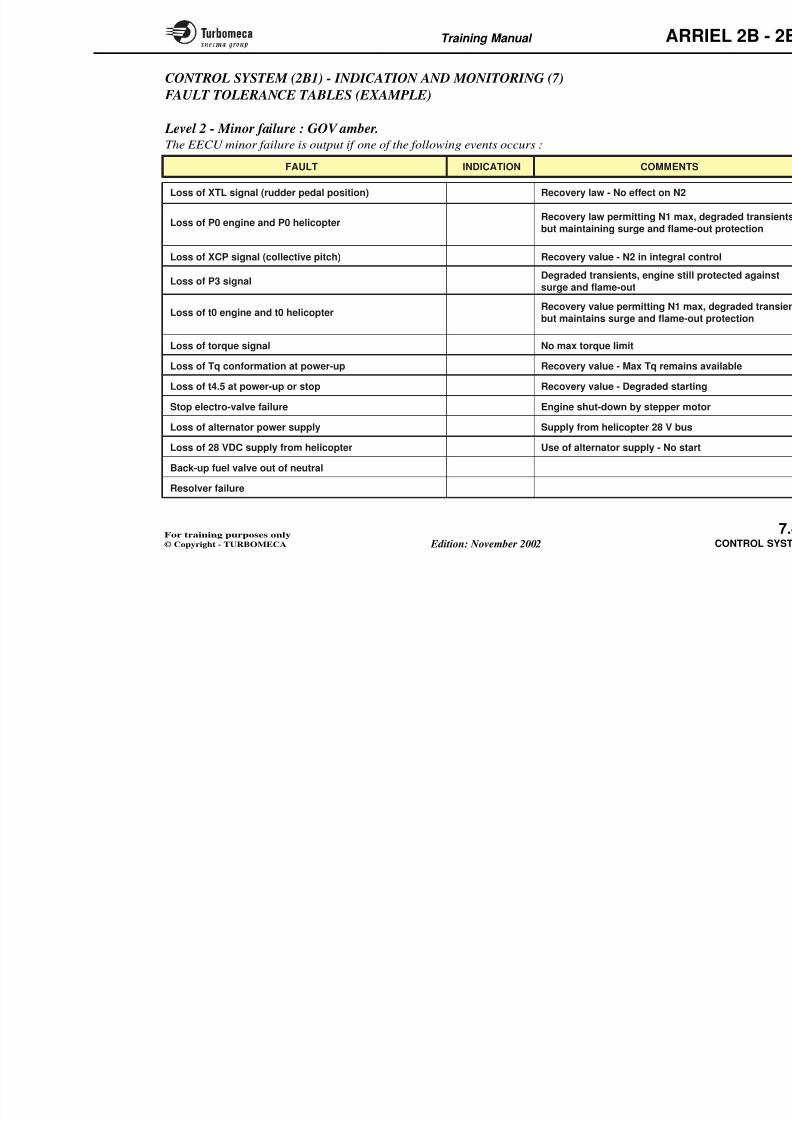
8/13/2019 Arriel_2B-2B1 11-02 En
http://slidepdf.com/reader/full/arriel2b-2b1-11-02-en 262/461
N1B & N1 Alt Stepper motor freeze 3 R ManualFAIL 2 - 00A0 or
FAIL 2 - 04A0
N1B (sensor) Use of N1 alternator 1 FA FAIL 2 - 0020
N1 (alternator) Use of N1B sensor 1 FA
N2B Use of N2C 1 FA FAIL 2 - 0010
N2C Use of N2B 1 FA FAIL 2 - 0040
N2B & N2C Stepper motor freeze 3 R FAIL 2 - 0050 Manual
In normEECU uFAIL 2 - 0080
orFAIL 2 - 0480
In normEECU u
CInput Effect on EECU operation Level CWP VEMD Message
Training Manual ARR
CONTROL SYSTEM (2B1) - INDICATION AND
MONITORING (4)
Fault tolerance, Indication and Management Fault indication
There are three levels of indication :
8/13/2019 Arriel_2B-2B1 11-02 En
http://slidepdf.com/reader/full/arriel2b-2b1-11-02-en 263/461
Fault tolerance
In the event of a fault the system automatically reconfiguresitself, without losing the essential functions, i. e. N1 and N2control, acceleration and deceleration control. For these
functions the software has recovery laws which it will useif a main control input becomes invalid.
In normal operation, channel A is the prefered channel.The system will only change to channel B if channel A hasa major failure.
- If a minor fault affects channel A,the system remainson channel A
- If a fault affects a main control law on channel A, it will use a recovery law.
- If a fault or faults affect a main control law and itsrecovery law, the system changes automatically tochannel B
- If a fault or faults affect a main control law and therecovery law of both channels, the system freezes thestepper motor automatically and enables the back-up system.
There are three levels of indication :
- Level 3 - Major failure : stepp
- Level 2 - Minor failure : respaffected but the essenare ensured
- Level 1 - Minor fault : no effect
There are two lights in the cockpit to a GOV red and GOV amber:
- The GOV red indicates a majo
- The GOV amber indicates a minalso indicates a minor fault
N1 < 20 %.
Note : The control system will alwawhich can receive informatiunless an internal malfunctiona major failure.
Training Manual ARR
Channel BAA: Failure level 2A: Failure level 1A: No failure
ChCh in control ACh in control ACh in control A
Channel A
FAULT TOLERANCE
8/13/2019 Arriel_2B-2B1 11-02 En
http://slidepdf.com/reader/full/arriel2b-2b1-11-02-en 264/461
GOV
GOV
GOV
B: No failure
Ch. EEC
GOV
B: Failure level 1
Ch.
EECGOV
B: Failure level 2
Ch.
EECGOV
B: Failure level 3
Ch.
EECGOV
Ch. in control: AEECU: Minor failure
GOV: Amber
Ch. in control: A
EECU: Minor failureGOV: Amber
Ch. in control: A
EECU: Minor failureGOV: Amber
Ch. in control: A
EECU: Minor failureGOV: Amber
Ch. in control: AEECU: Redun. failure
GOV: Flashing amber
Ch. in control: A
EECU: Redun. failureGOV: Flashing amber
Ch. in control: A
EECU: Redun. failureGOV: Flashing amber
Ch. in control: A
EECU: Redun. failureGOV: Flashing amber
Ch. in control: AEECU: Redun. failure
GOV: Flashing amber
Ch. in control: A
EECU: Redun. failureGOV: Flashing amber
Ch. in control: A
EECU: Redun. failureGOV: Flashing amber
Ch. in control: A
EECU: No failureGOV: No
FAULT INDICATION
GOV Red
Major failure - Le(Stepper motor fr
Fault
Detectionand
IndicationGOV AmberMinor failure - Le
(response time messential control
GOV Flashing amMinor fault - Leve
(no effect on eng
Channel ANote : The control system will always be on channel
A, which can receive information fromchannel B unless an internal malfunction of
Training Manual ARR
CONTROL SYSTEM (2B1) - INDICATION AND
MONITORING (5)
Fault management
For each input signal the EECU has a set of criteria with
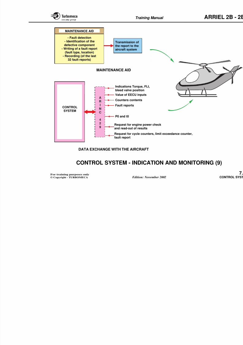
8/13/2019 Arriel_2B-2B1 11-02 En
http://slidepdf.com/reader/full/arriel2b-2b1-11-02-en 265/461
For each input signal, the EECU has a set of criteria withwhich it can decide if the signal is valid. The tables on the
following pages show the logic used by the EECU in theevent of an invalid signal. They also show the associated
fault level, the CWP indication and the VEMD indicationwhere applicable.
Note 1 : CWP : Central Warning Panel
VEMD : Vehicle and Engine Multifunction Display (indication and messagescreen).
Note 2 : In the following pages, the CWP indicationscorrespond to :
R = GOV Red
A = GOV Amber
FA = GOV Amber flashing when N1 < 20 %
Training Manual ARR
CONTROL SYSTEM (2B1) - INDICATION AND MONITORING (6)
FAULT TOLERANCE TABLES (EXAMPLE)
Level 1 - Minor fault : GOV amber flashing if N1 < 20%.
8/13/2019 Arriel_2B-2B1 11-02 En
http://slidepdf.com/reader/full/arriel2b-2b1-11-02-en 266/461
The EECU redundancy failure is output if one of the following signals is declared invalid :
- Engine t4.5
- Helicopter t4.5
- Start switch failure after start (flight mode automatically selected)
- Engine P0 with helicopter P0 valid
- Single N1 signal
- Single N2 signal
- Single stepper motor
- Tq conformation after power-up
- t4.5 conformation after power-up
- Helicopter P0 with engine P0 valid
- Engine t0 failure
- Helicopter t0
Training Manual ARR
CONTROL SYSTEM (2B1) - INDICATION AND MONITORING (7)
FAULT TOLERANCE TABLES (EXAMPLE)
Level 2 - Minor failure : GOV amber.
The EECU minor failure is output if one of the following events occurs :
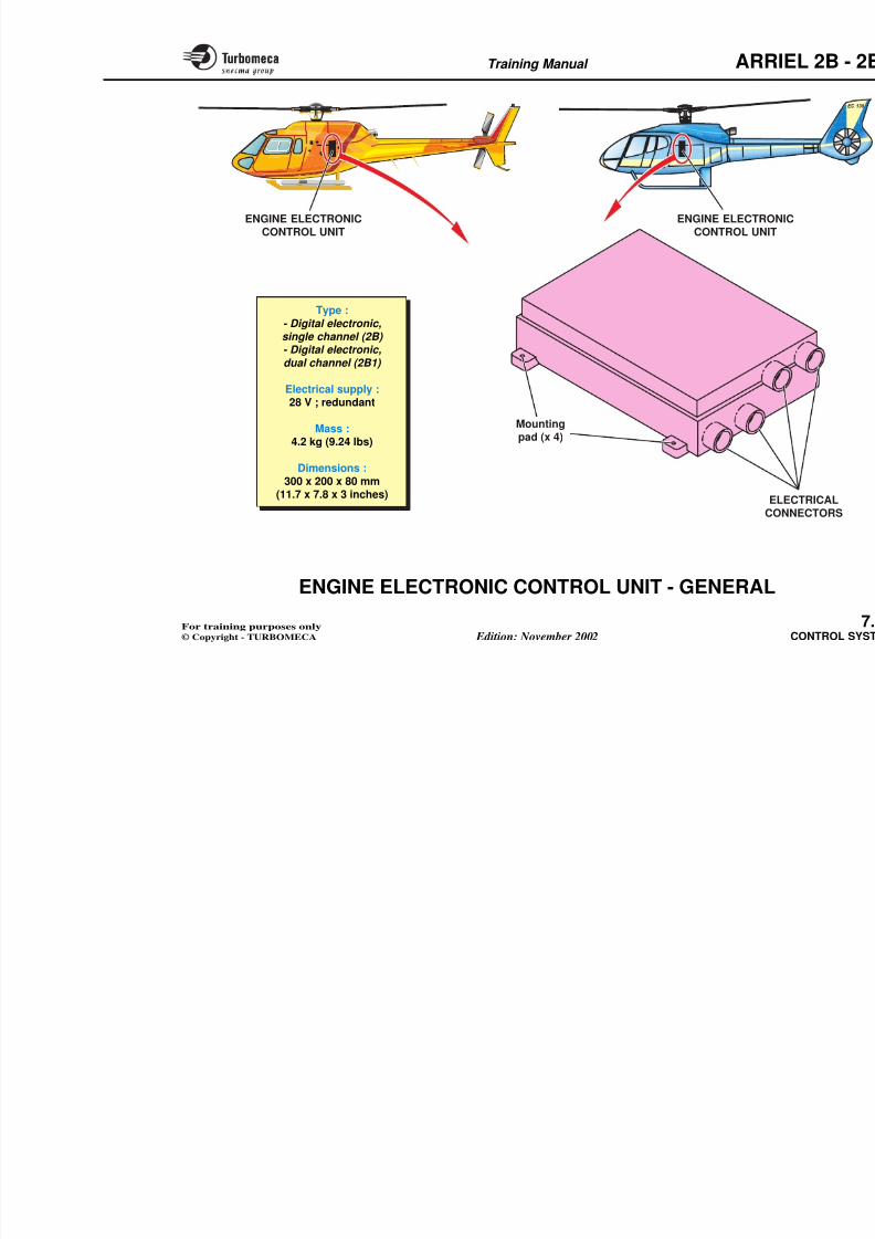
8/13/2019 Arriel_2B-2B1 11-02 En
http://slidepdf.com/reader/full/arriel2b-2b1-11-02-en 267/461
FAULT INDICATION COMMENTS
Loss of XTL signal (rudder pedal position)
Loss of P0 engine and P0 helicopter
Loss of XCP signal (collective pitch)
Loss of P3 signal
Loss of t0 engine and t0 helicopter
Loss of torque signal
Loss of Tq conformation at power-up
Loss of t4.5 at power-up or stop
Stop electro-valve failure
Loss of alternator power supply
Loss of 28 VDC supply from helicopter
Back-up fuel valve out of neutral
Recovery law - No effect on N2
Recovery law permitting N1 max, d
but maintaining surge and flame-o
Recovery value permitting N1 max
but maintains surge and flame-out
Recovery value - N2 in integral con
Degraded transients, engine still p
surge and flame-out
No max torque limit
Recovery value - Max Tq remains
Recovery value - Degraded startin
Engine shut-down by stepper mot
Supply from helicopter 28 V bus
Use of alternator supply - No start
Training Manual ARR
CONTROL SYSTEM (2B1) - INDICATION AND MONITORING (8)
FAULT TOLERANCE TABLES (EXAMPLE)
Level 3 - Major failure : GOV red.
8/13/2019 Arriel_2B-2B1 11-02 En
http://slidepdf.com/reader/full/arriel2b-2b1-11-02-en 268/461
The EECU major failure is output if one of the following events occurs :
- Dual stepper motor failure
- P0 failure, P0 helicopter failure and P3 failure
- t0 failure, t0 helicopter failure and P3 failure
- "Stop" / "flight" selector failure in stop mode
- Hardware / watchdog failure
- Double N1 failure
- Double N2 failure.
Training Manual ARR
CONTROL SYSTEM - INDICATION AND
MONITORING (9)
Maintenance aid
The system ensures the following functions :
Data exchange with the aircraft
The EECU exchanges data with the aserial data link ARINC 429.
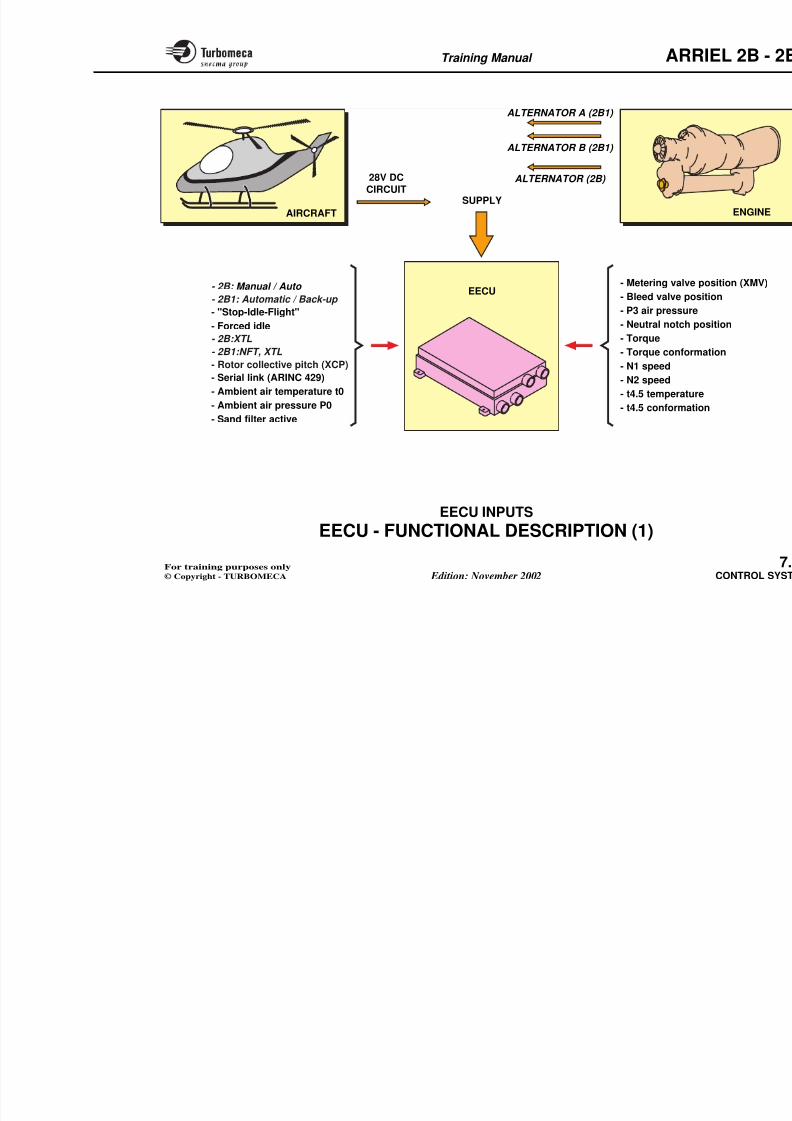
8/13/2019 Arriel_2B-2B1 11-02 En
http://slidepdf.com/reader/full/arriel2b-2b1-11-02-en 269/461
The system ensures the following functions :
- Fault detection
- Fault isolation and identification of the componentaffected
- Writing of a fault report containing information such as
fault type, location
- Transmission of the fault report to the memory or to thehelicopter system
- Recording in the memory of the last 32 fault reports.
It can receive :
- P0 and t0
- The request for a performance chresults
- The request to read the cycle and h
- The request for a fault report.
It can transmit :
- The indications of torque, FLI, ble
- The value of EECU inputs and ou
- The counters contents
- The reports.
Two types of messages can be consi
- Standard messages which are cont
M i hi h
Training Manual ARR
Transmission ofthe report to thei ft t
MAINTENANCE AID
- Fault detection- Identification of the
defective component- Writing of a fault report
8/13/2019 Arriel_2B-2B1 11-02 En
http://slidepdf.com/reader/full/arriel2b-2b1-11-02-en 270/461
P0 and t0
Fault reports
Counters contents
Value of EECU inputs
Indications Torque, FLI,
bleed valve position
CONTROLSYSTEM
MAINTENANCE AID
aircraft system- Writing of a fault report
(fault type, location)- Recording (of the last
32 fault reports)
A
RI
NC
42
9Request for engine power checkand read-out of results
Request for cycle counters, limit exceedance counter,
fault report
Training Manual ARR
ENGINE ELECTRONIC CONTROL UNIT -
GENERAL
Function
The EECU controls and monitors the engine operation.
Main components
- Electrical connectors
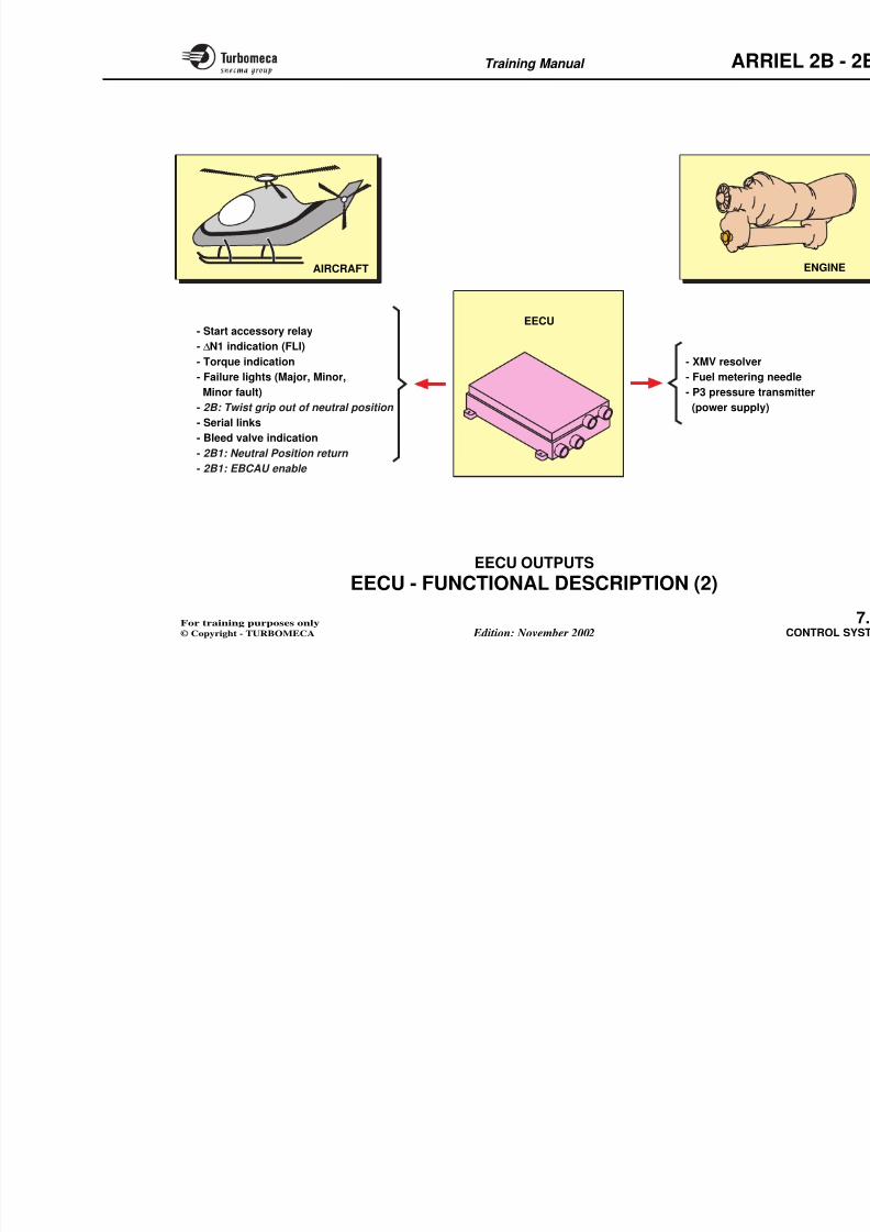
8/13/2019 Arriel_2B-2B1 11-02 En
http://slidepdf.com/reader/full/arriel2b-2b1-11-02-en 271/461
g p
Position
- The EECU is installed in a helicopter compartment.
Main characteristics- 2B : Single channel digital electronic
- 2B1 : Dual channel digital electronic
- Redundant electrical supply : 28 V
- Mass : 4.2 kg (9.24 lbs)
- Dimensions : 300 x 200 x 80 mm (11.7 x 8 x 3 inches).
- Mounting pads.
Training Manual ARR
8/13/2019 Arriel_2B-2B1 11-02 En
http://slidepdf.com/reader/full/arriel2b-2b1-11-02-en 272/461
Type :
- Digital electronic,single channel (2B) - Digital electronic,
dual channel (2B1)
Electrical supply :28 V ; redundant
Mass :4.2 kg (9.24 lbs)
Dimensions :
300 x 200 x 80 mm(11.7 x 7.8 x 3 inches)
ENGINE ELECTRONICCONTROL UNIT
E
CO
ENGINE ELECTROCONTROL UNIT
Mountingpad (x 4)
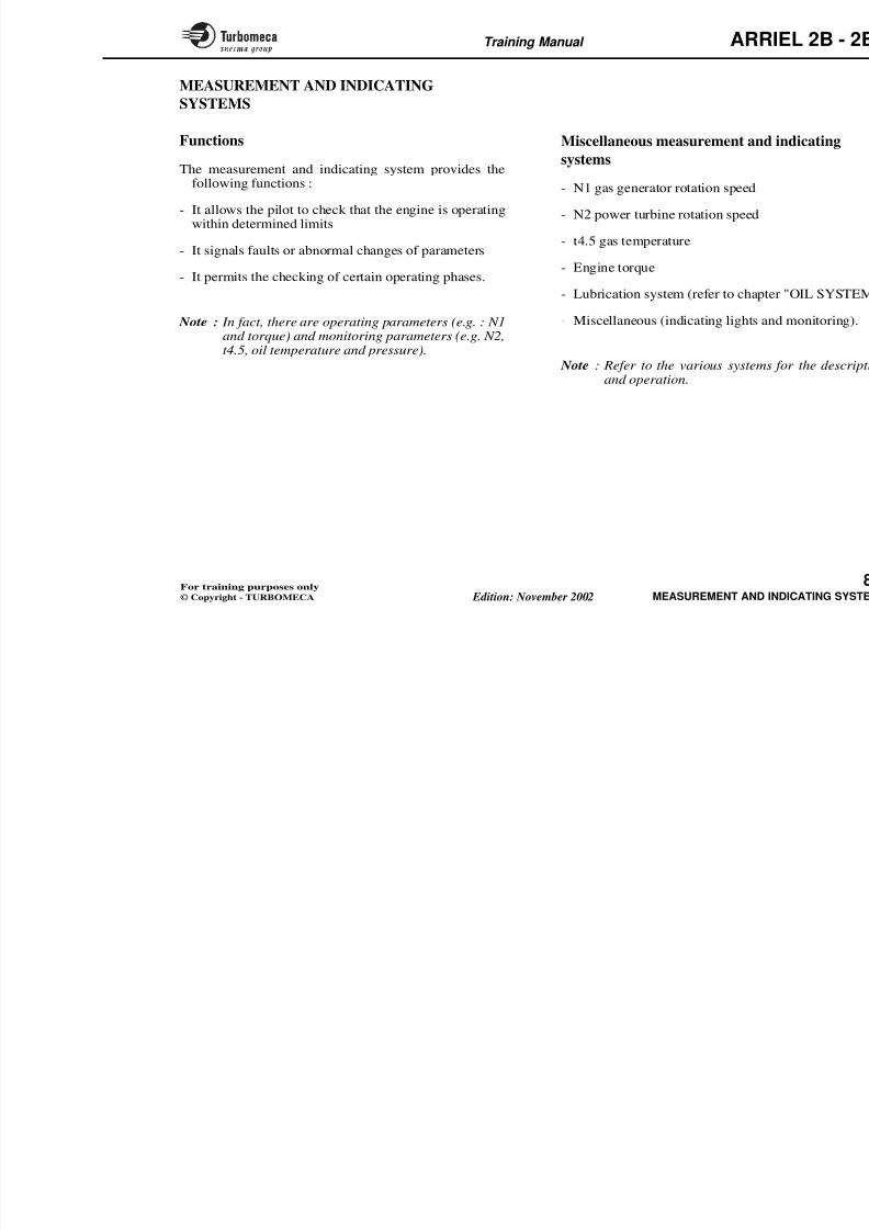
8/13/2019 Arriel_2B-2B1 11-02 En
http://slidepdf.com/reader/full/arriel2b-2b1-11-02-en 273/461
Training Manual ARR
ALTERNATOR B (2B1)
ALTERNATOR A (2B1)
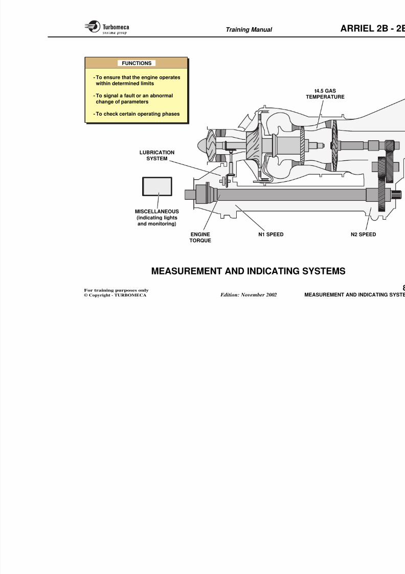
8/13/2019 Arriel_2B-2B1 11-02 En
http://slidepdf.com/reader/full/arriel2b-2b1-11-02-en 274/461
ALTERNATOR (2B)
SUPPLY
EECU
28V DC
CIRCUIT
- Metering valve p
- Bleed valve pos
- P3 air pressure
- Neutral notch po
- Torque
- Torque conform- N1 speed
- N2 speed
- t4.5 temperature
- t4.5 conformatio
- 2B: Manual / Auto
- 2B1: Automatic / Back-up
- "Stop-Idle-Flight"
- Forced idle
- 2B:XTL
- 2B1:NFT, XTL- Rotor collective pitch (XCP)
- Serial link (ARINC 429)
- Ambient air temperature t0
- Ambient air pressure P0
- Sand filter active
AIRCRAFT
Training Manual ARR
EECU - FUNCTIONAL DESCRIPTION (2)
EECU outputs
To the aircraft
Start accessory relay
To the engine
- Fuel metering needle
- P3 pressure transmitter
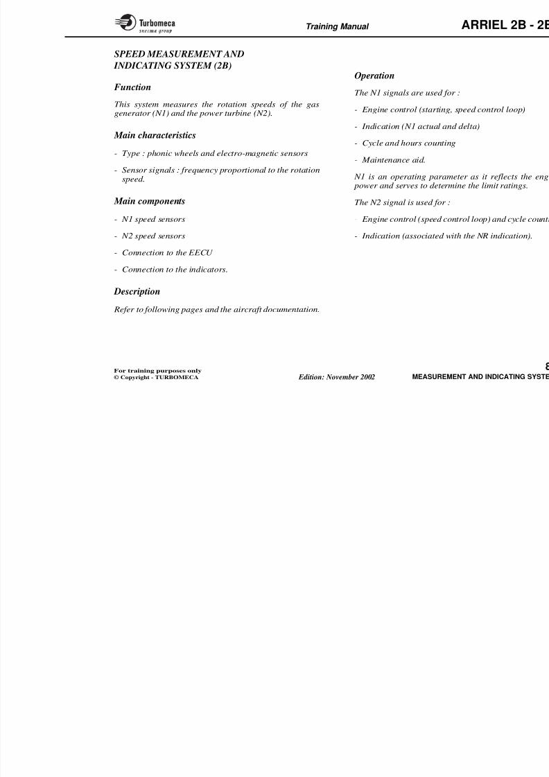
8/13/2019 Arriel_2B-2B1 11-02 En
http://slidepdf.com/reader/full/arriel2b-2b1-11-02-en 275/461
- Start accessory relay
- ∆N1 indication (FLI)
- Torque indication
- Fault lights
• Major failure• Minor failure
• Minor fault
- 2B: Twist grip out of neutral position
- Serial links
- Bleed valve position
- 2B1: Neutral Position return
- 2B1: EBCAU enable.
P3 pressure transmitter
- XMV resolver.
Training Manual ARR
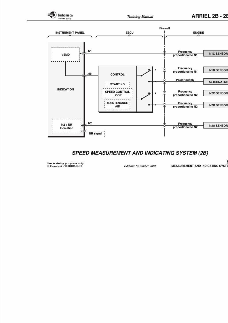
8/13/2019 Arriel_2B-2B1 11-02 En
http://slidepdf.com/reader/full/arriel2b-2b1-11-02-en 276/461
EECU
AIRCRAFT
- Start accessory relay
- ∆N1 indication (FLI)
- Torque indication
- Failure lights (Major, Minor,
Minor fault)- 2B: Twist grip out of neutral position
- Serial links
- Bleed valve indication
- 2B1: Neutral Position return
- 2B1: EBCAU enable
- XMV resolver
- Fuel metering n
- P3 pressure tra (power supply)
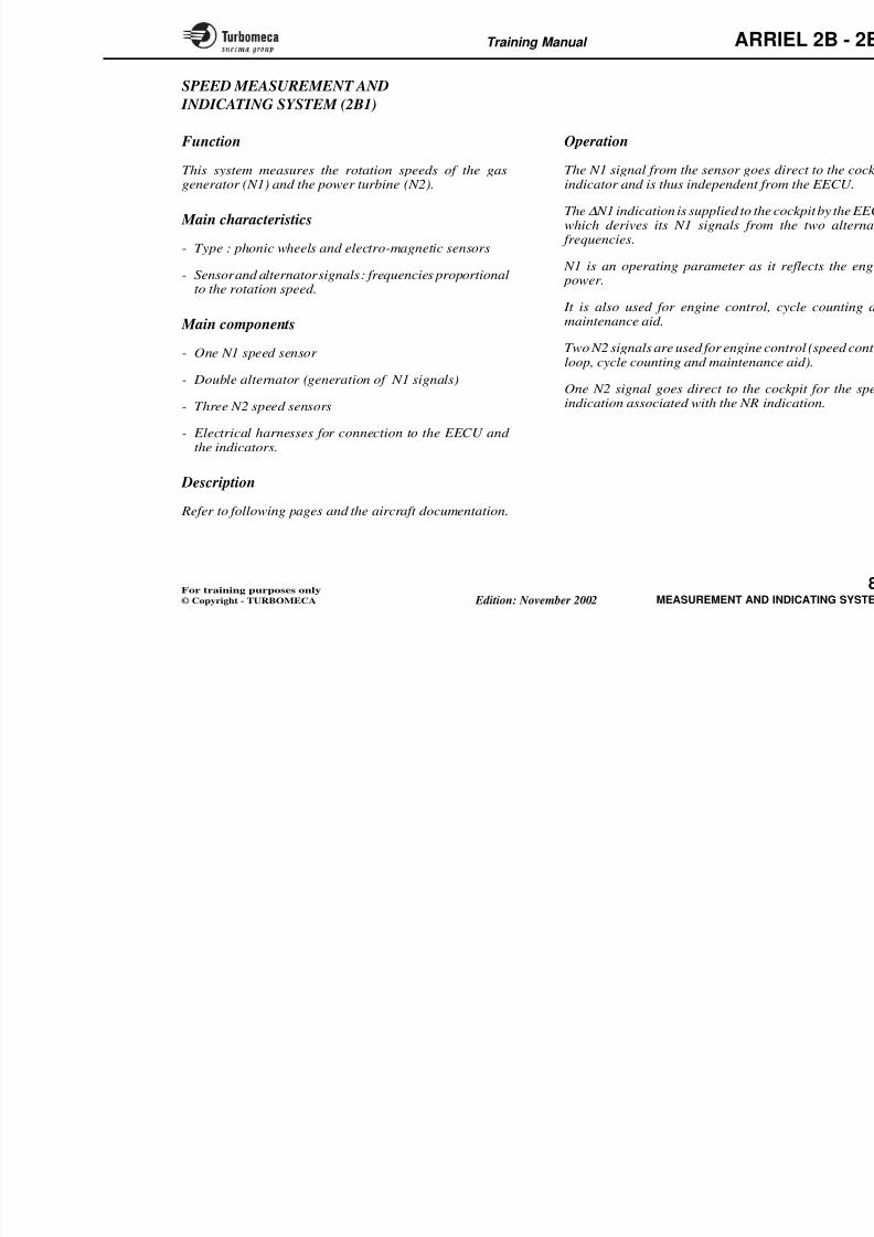
8/13/2019 Arriel_2B-2B1 11-02 En
http://slidepdf.com/reader/full/arriel2b-2b1-11-02-en 277/461
Training Manual ARR
8-MEASUREMENT AND
INDICATING SYSTEMS
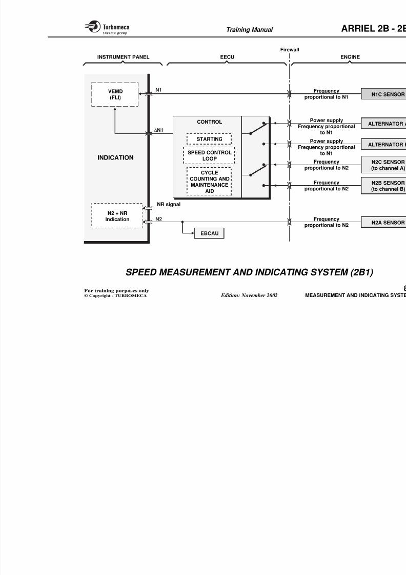
8/13/2019 Arriel_2B-2B1 11-02 En
http://slidepdf.com/reader/full/arriel2b-2b1-11-02-en 278/461
INDICATING SYSTEMS- Measurement and indicating systems (77-00-00) ............ 8
- Speed measurement and indicating system (77-00-00) .. 8
- N1 speed sensor (77-11-00) ................................................ 8
- N2 speed sensors (77-12-00) .............................................. 8- t4.5 gas temperature measurement and
indicating system (77-00-00) ............................................. 8
- t4.5 thermocouple probes (77-21-00) ............................... 8
- t4.5 conformation box (72-43-00) ..................................... 8
- Torque measurement and indicating system (77-00-00) 8- Torquemeter (72-61-00) ..................................................... 8
- Torque sensor (72-61-00) ................................................... 8
- Torque conformation box (72-61-00) ............................... 8
- Indicators............................................................................ 8
Mi ll i di ti 8
Training Manual ARR
MEASUREMENT AND INDICATING
SYSTEMS
Functions
The measurement and indicating system provides thef ll i f i
Miscellaneous measurement and
systems
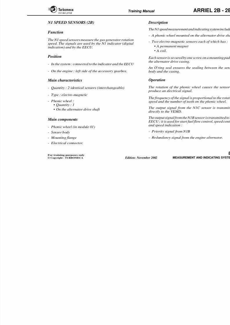
8/13/2019 Arriel_2B-2B1 11-02 En
http://slidepdf.com/reader/full/arriel2b-2b1-11-02-en 279/461
following functions :
- It allows the pilot to check that the engine is operatingwithin determined limits
- It signals faults or abnormal changes of parameters
- It permits the checking of certain operating phases.
Note : In fact, there are operating parameters (e.g. : N1and torque) and monitoring parameters (e.g. N2,t4.5, oil temperature and pressure).
- N1 gas generator rotation speed
- N2 power turbine rotation speed
- t4.5 gas temperature
- Engine torque- Lubrication system (refer to chapt
- Miscellaneous (indicating lights an
Note : Refer to the various systemsand operation.
Training Manual ARR
- To ensure that the engine operateswithin determined limits
FUNCTIONS
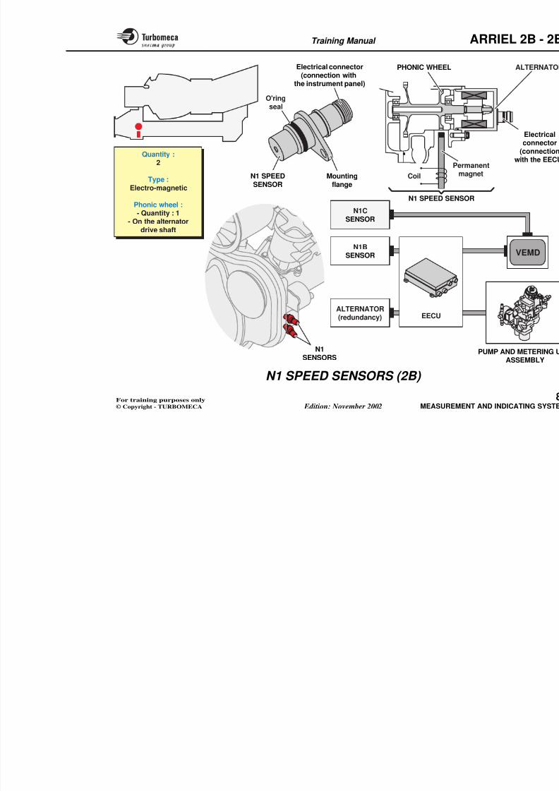
8/13/2019 Arriel_2B-2B1 11-02 En
http://slidepdf.com/reader/full/arriel2b-2b1-11-02-en 280/461
N2 ENGINETORQUE
N1 SPEED
within determined limits
- To signal a fault or an abnormalchange of parameters
- To check certain operating phases
t4.5 GASTEMPERATURE
LUBRICATIONSYSTEM
MISCELLANEOUS
(indicating lightsand monitoring)
Training Manual ARR
SPEED MEASUREMENT AND
INDICATING SYSTEM (2B)
Function
This system measures the rotation speeds of the gasgenerator (N1) and the power turbine (N2)
Operation
The N1 signals are used for :
- Engine control (starting, speed co
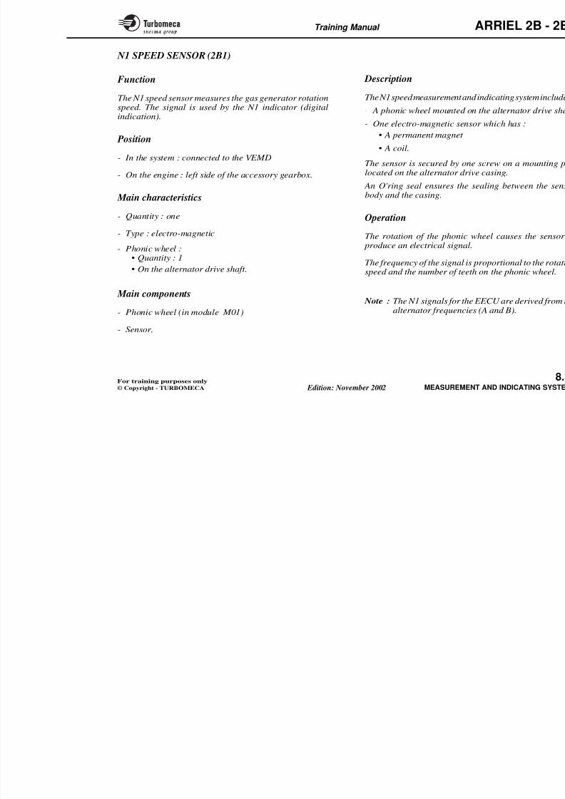
8/13/2019 Arriel_2B-2B1 11-02 En
http://slidepdf.com/reader/full/arriel2b-2b1-11-02-en 281/461
generator (N1) and the power turbine (N2).
Main characteristics
- Type : phonic wheels and electro-magnetic sensors
- Sensor signals : frequency proportional to the rotationspeed.
Main components
- N1 speed sensors
- N2 speed sensors
- Connection to the EECU
- Connection to the indicators.
Description
Refer to following pages and the aircraft documentation.
- Indication (N1 actual and delta)
- Cycle and hours counting
- Maintenance aid.
N1 is an operating parameter as it power and serves to determine the li
The N2 signal is used for :
- Engine control (speed control loop
- Indication (associated with the NR
Training Manual ARR
Firewall
ENGINEECUINSTRUMENT PANEL
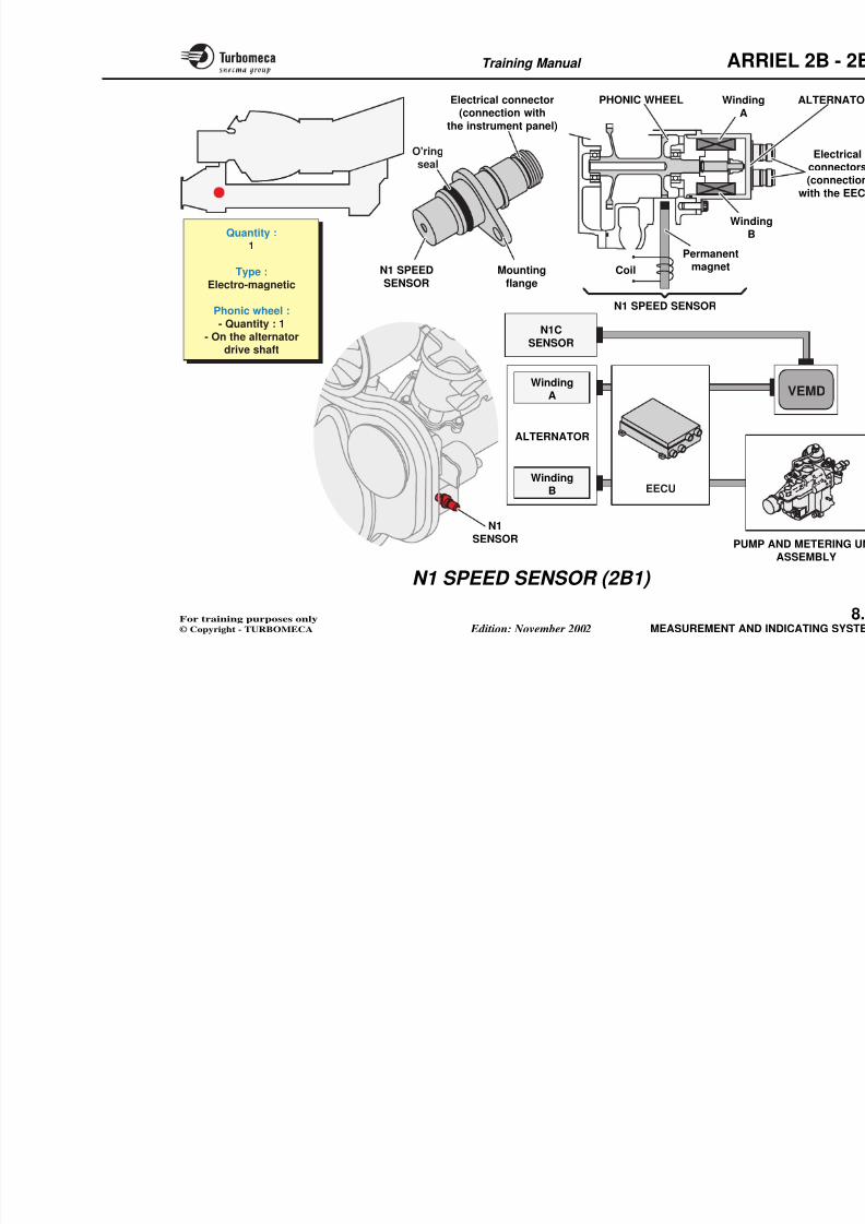
8/13/2019 Arriel_2B-2B1 11-02 En
http://slidepdf.com/reader/full/arriel2b-2b1-11-02-en 282/461
CONTROL
STARTING
SPEED CONTROLLOOP
MAINTENANCEAID
VEMD
INDICATION
Frequencyproportional to N1
Frequency
proportional to N1
Frequencyproportional to N2
Frequencyproportional to N2
Frequencyproportional to N2
Power supply
NR signal
N1
N2
∆N1
N2 + NRIndication
Training Manual ARR
SPEED MEASUREMENT AND
INDICATING SYSTEM (2B1)
Function
This system measures the rotation speeds of the gasgenerator (N1) and the power turbine (N2)
Operation
The N1 signal from the sensor goes indicator and is thus independent fro
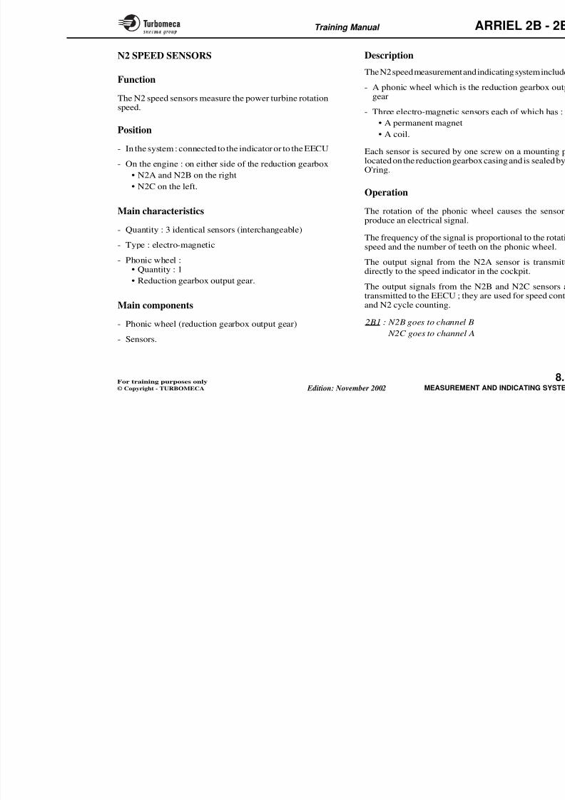
8/13/2019 Arriel_2B-2B1 11-02 En
http://slidepdf.com/reader/full/arriel2b-2b1-11-02-en 283/461
generator (N1) and the power turbine (N2).
Main characteristics
- Type : phonic wheels and electro-magnetic sensors
- Sensor and alternator signals : frequencies proportionalto the rotation speed.
Main components
- One N1 speed sensor
- Double alternator (generation of N1 signals)
- Three N2 speed sensors
- Electrical harnesses for connection to the EECU and the indicators.
Description
Refer to following pages and the aircraft documentation
indicator and is thus independent fro
The∆ N1 indication is supplied to the which derives its N1 signals from
frequencies.
N1 is an operating parameter as it
power.
It is also used for engine control, maintenance aid.
Two N2 signals are used for engine coloop, cycle counting and maintenanc
One N2 signal goes direct to the coindication associated with the NR in
Training Manual ARR
Firewall
ENGINEEECUINSTRUMENT PANEL
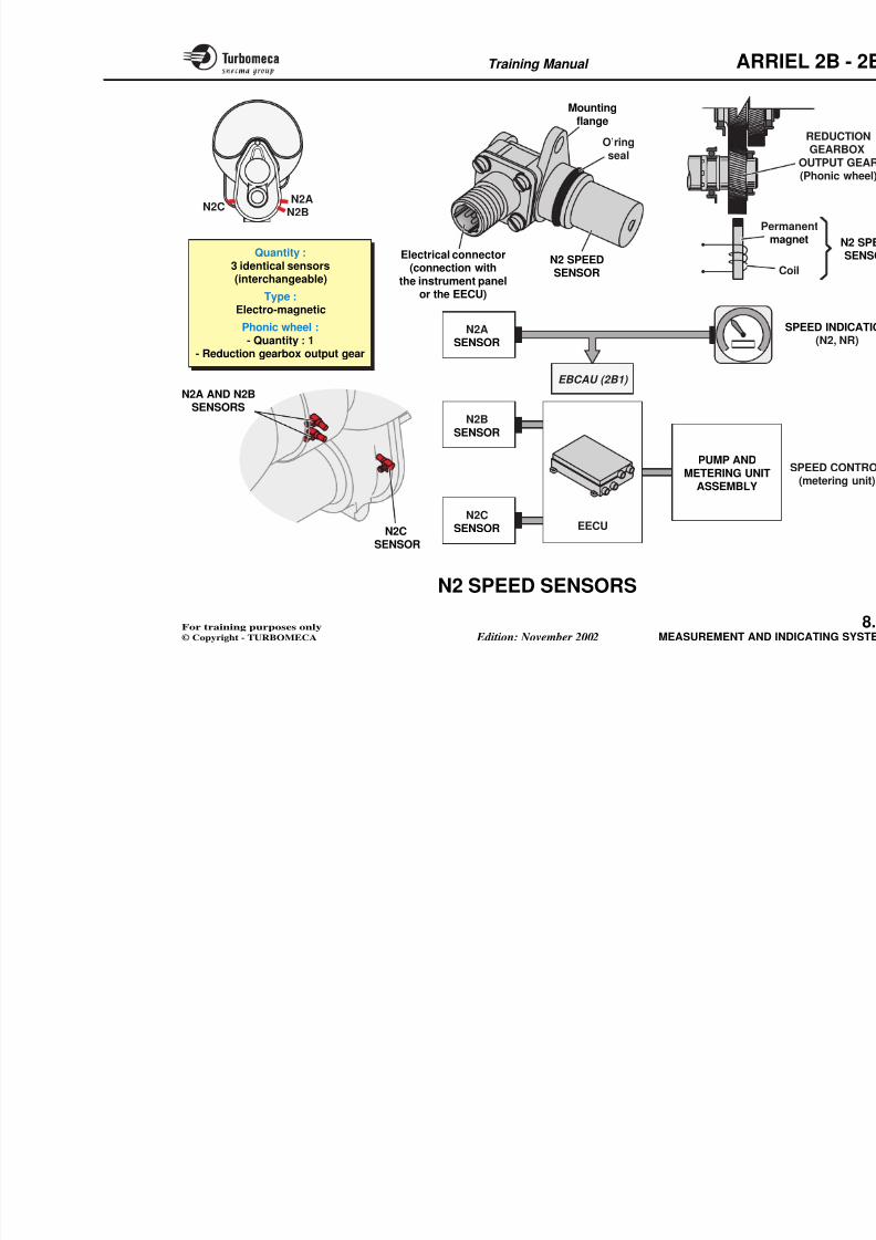
8/13/2019 Arriel_2B-2B1 11-02 En
http://slidepdf.com/reader/full/arriel2b-2b1-11-02-en 284/461
CONTROL
STARTING
EBCAU
SPEED CONTROL
LOOP
Frequency
proportional to N1
Power supply
Frequency proportionalto N1
Frequencyproportional to N2
Frequencyproportional to N2
Frequencyproportional to N2
Power supplyFrequency proportional
to N1
CYCLE
COUNTING AND
MAINTENANCEAID
VEMD(FLI)
INDICATION
NR signal
N1
N2
∆N1
N2 + NRIndication
Training Manual ARR
N1 SPEED SENSORS (2B)
Function
The N1 speed sensors measure the gas generator rotationspeed. The signals are used by the N1 indicator (digitalindication) and by the EECU.
Description
The N1 speed measurement and indica
- A phonic wheel mounted on the al
- Two electro-magnetic sensors eac• A permanent magnet
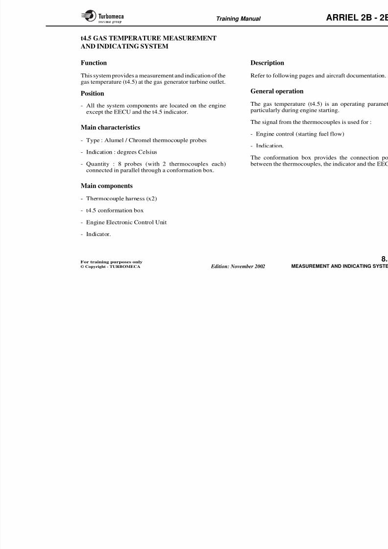
8/13/2019 Arriel_2B-2B1 11-02 En
http://slidepdf.com/reader/full/arriel2b-2b1-11-02-en 285/461
) y
Position
- In the system : connected to the indicator and the EECU
- On the engine : left side of the accessory gearbox.
Main characteristics
- Quantity : 2 identical sensors (interchangeable)
- Type : electro-magnetic
- Phonic wheel :
• Quantity : 1
• On the alternator drive shaft
Main components
- Phonic wheel (in module 01)
- Sensor body
• A coil.
Each sensor is secured by one screw othe alternator drive casing.
An O'ring seal ensures the sealing
body and the casing.
Operation
The rotation of the phonic wheel c produce an electrical signal.
The frequency of the signal is proporspeed and the number of teeth on the
The output signal from the N1C sedirectly to the VEMD.
The output signal from the N1B senso EECU ; it is used for start fuel flow coand speed indication :
- Priority signal from N1B
Training Manual ARR
PHONIC WHEELElectrical connector(connection with
the instrument panel)
O'ringseal
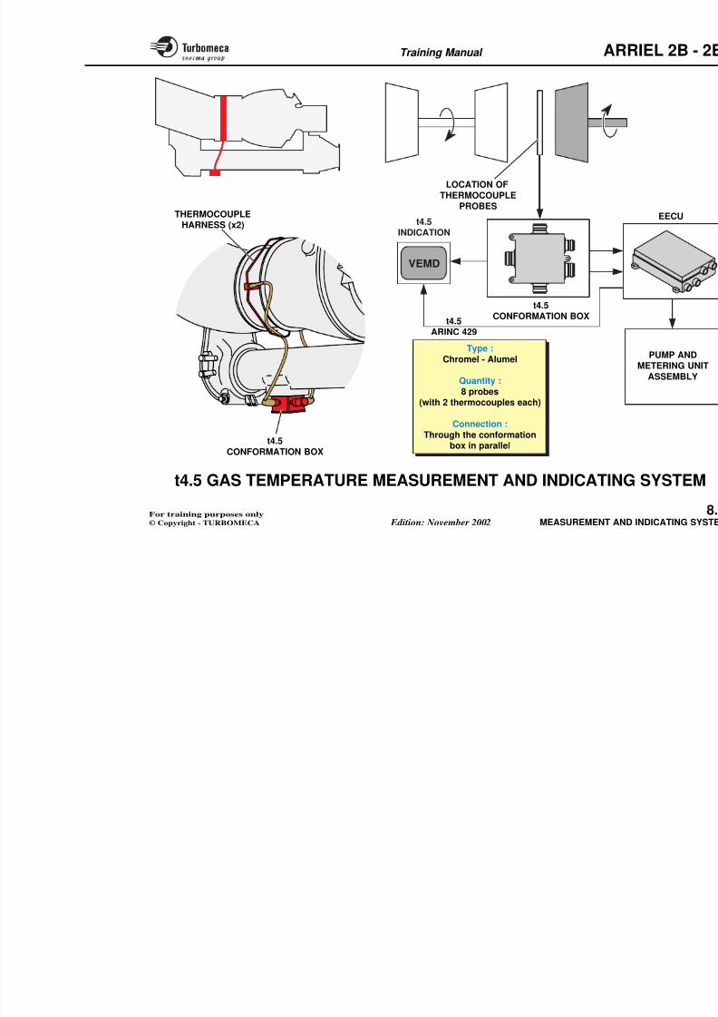
8/13/2019 Arriel_2B-2B1 11-02 En
http://slidepdf.com/reader/full/arriel2b-2b1-11-02-en 286/461
N1CSENSOR
N1BSENSOR
EECU
N1 SPEED SENSOR
Coil
Permanent
magnetN1 SPEEDSENSOR
Mountingflange
ALTERNATOR(redundancy)
Quantity :2
Type :Electro-magnetic
Phonic wheel :- Quantity : 1
- On the alternatordrive shaft
Training Manual ARR
N1 SPEED SENSOR (2B1)
Function
The N1 speed sensor measures the gas generator rotationspeed. The signal is used by the N1 indicator (digitalindication).
Description
The N1 speed measurement and indica
- A phonic wheel mounted on the al
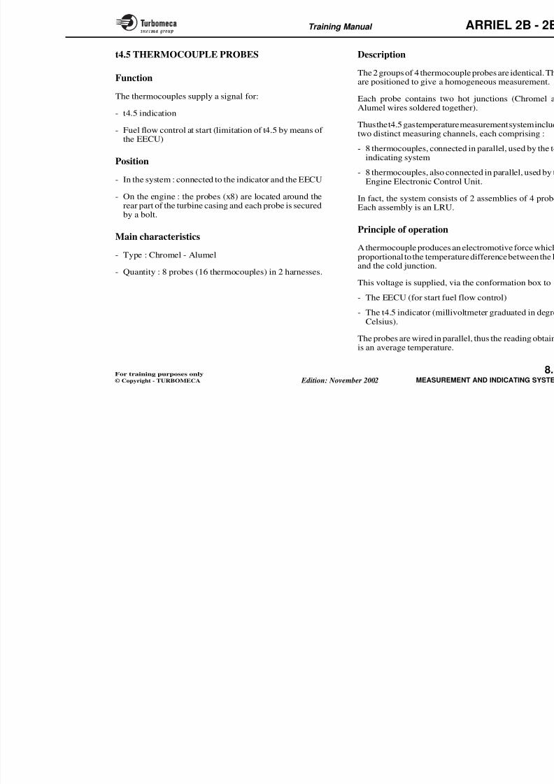
8/13/2019 Arriel_2B-2B1 11-02 En
http://slidepdf.com/reader/full/arriel2b-2b1-11-02-en 287/461
)
Position
- In the system : connected to the VEMD
- On the engine : left side of the accessory gearbox.
Main characteristics
- Quantity : one
- Type : electro-magnetic
- Phonic wheel :• Quantity : 1
• On the alternator drive shaft.
Main components
- Phonic wheel (in module M01)
Sensor
- One electro-magnetic sensor whic
• A permanent magnet
• A coil.
The sensor is secured by one screwlocated on the alternator drive casin
An O'ring seal ensures the sealing body and the casing.
Operation
The rotation of the phonic wheel c produce an electrical signal.
The frequency of the signal is proporspeed and the number of teeth on the
Note : The N1 signals for the EECUalternator frequencies (A and
Training Manual ARR
PHONIC WHEEL Winding
A
Electrical connector(connection with
the instrument panel)
O'ringseal
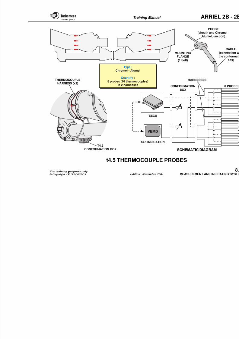
8/13/2019 Arriel_2B-2B1 11-02 En
http://slidepdf.com/reader/full/arriel2b-2b1-11-02-en 288/461
WindingA
ALTERNATOR
WindinB
N1 SPEEDSENSOR Mountingflange
WindingB
Coil
Quantity :1
Type :Electro-magnetic
Phonic wheel :
- Quantity : 1- On the alternator
drive shaft
N1C
SENSOR
EECU
N1 SPEED SENSOR
Permanentmagnet
Training Manual ARR
N2 SPEED SENSORS
Function
The N2 speed sensors measure the power turbine rotationspeed.
Description
The N2 speed measurement and indica
- A phonic wheel which is the reducgear
- Three electro-magnetic sensors ea
A t t
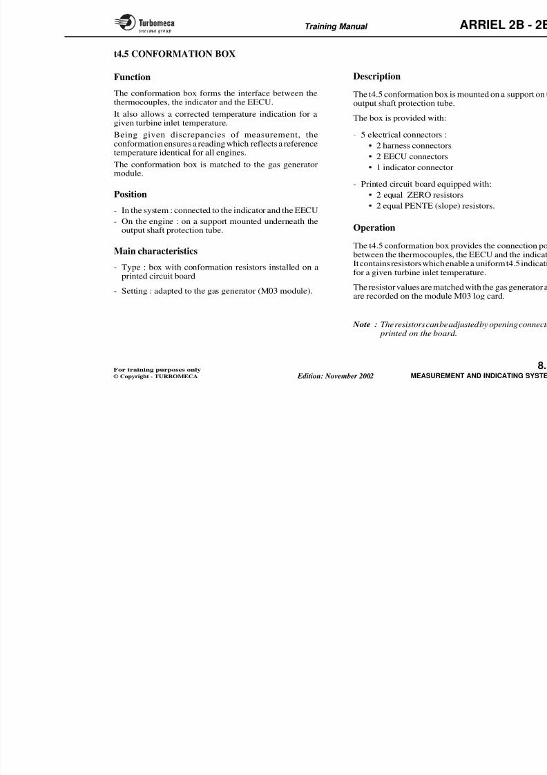
8/13/2019 Arriel_2B-2B1 11-02 En
http://slidepdf.com/reader/full/arriel2b-2b1-11-02-en 289/461
Position
- In the system : connected to the indicator or to the EECU
- On the engine : on either side of the reduction gearbox
•
N2A and N2B on the right• N2C on the left.
Main characteristics
- Quantity : 3 identical sensors (interchangeable)
- Type : electro-magnetic
- Phonic wheel :• Quantity : 1
• Reduction gearbox output gear.
Main components
- Phonic wheel (reduction gearbox output gear)
• A permanent magnet
• A coil.
Each sensor is secured by one screwlocated on the reduction gearbox casinO'ring.
Operation
The rotation of the phonic wheel cproduce an electrical signal.
The frequency of the signal is proporspeed and the number of teeth on the
The output signal from the N2A sdirectly to the speed indicator in the
The output signals from the N2B atransmitted to the EECU ; they are usand N2 cycle counting.
2B1 : N2B goes to channel B
N2C goes to channel A
Training Manual ARR
Mountingflange
O’ring
seal
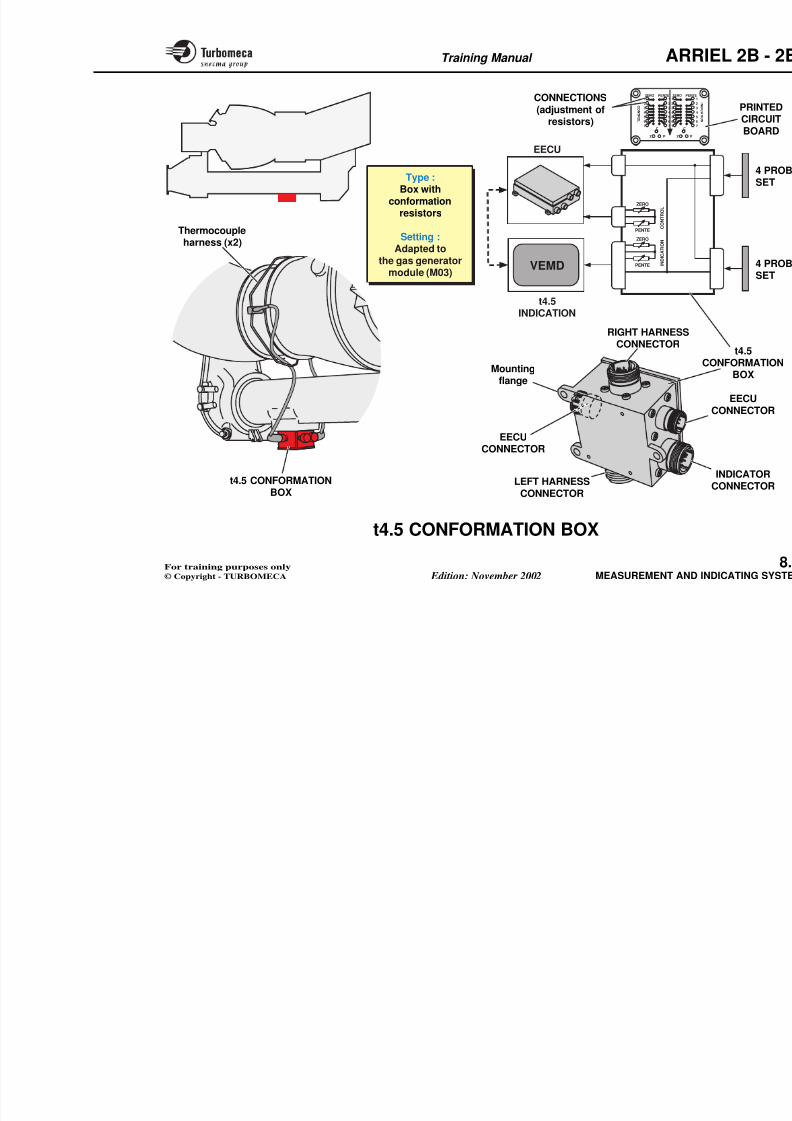
8/13/2019 Arriel_2B-2B1 11-02 En
http://slidepdf.com/reader/full/arriel2b-2b1-11-02-en 290/461
N2CN2A
N2B
Electrical connector(connection with
the instrument panelor the EECU)
N2 SPEED
SENSOR
N2ASENSOR
EBCAU (2B1)
N2BSENSOR
N2C
Pem
N2A AND N2BSENSORS
Quantity :3 identical sensors
(interchangeable)
Type :Electro-magnetic
Phonic wheel :- Quantity : 1
- Reduction gearbox output gear
PUMP ANDMETERING UNIT
ASSEMBLY
Training Manual ARR
t4.5 GAS TEMPERATURE MEASUREMENT
AND INDICATING SYSTEM
Function
This system provides a measurement and indication of thegas temperature (t4.5) at the gas generator turbine outlet.
Description
Refer to following pages and aircraf
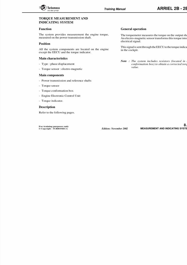
8/13/2019 Arriel_2B-2B1 11-02 En
http://slidepdf.com/reader/full/arriel2b-2b1-11-02-en 291/461
gas temperature (t4.5) at the gas generator turbine outlet.
Position
- All the system components are located on the engineexcept the EECU and the t4.5 indicator.
Main characteristics
- Type : Alumel / Chromel thermocouple probes
- Indication : degrees Celsius
- Quantity : 8 probes (with 2 thermocouples each)connected in parallel through a conformation box.
Main components
- Thermocouple harness (x2)
- t4.5 conformation box
- Engine Electronic Control Unit
General operation
The gas temperature (t4.5) is an oparticularly during engine starting.
The signal from the thermocouples i
- Engine control (starting fuel flow)
- Indication.
The conformation box provides thbetween the thermocouples, the indic
Training Manual ARR
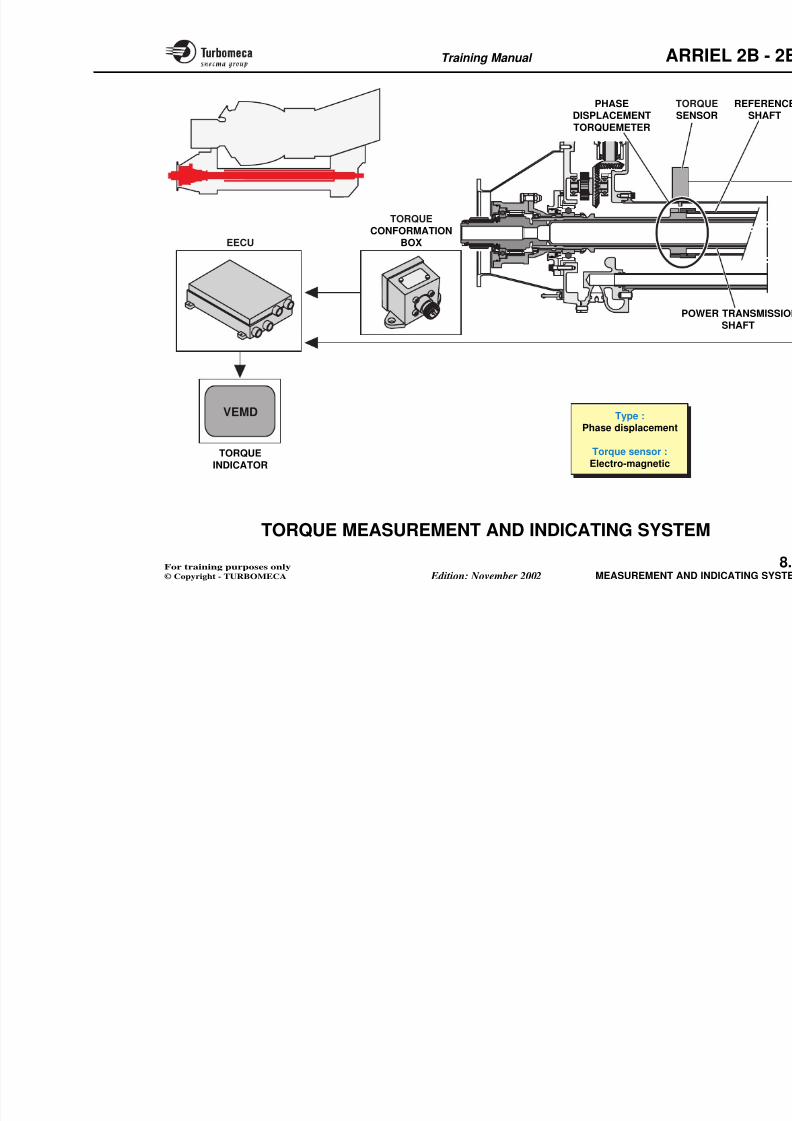
8/13/2019 Arriel_2B-2B1 11-02 En
http://slidepdf.com/reader/full/arriel2b-2b1-11-02-en 292/461
Type :
Chromel - Alumel
Quantity :
8 probes(with 2 thermocouples each)
Connection :
LOCATION OF
THERMOCOUPLEPROBES
t4.5CONFORMATION BOX
t4.5INDICATION
THERMOCOUPLE
HARNESS (x2)
t4.5ARINC 429
VEMD
Training Manual ARR
t4.5 THERMOCOUPLE PROBES
Function
The thermocouples supply a signal for:
- t4.5 indication
Description
The 2 groups of 4 thermocouple probeare positioned to give a homogeneou
Each probe contains two hot juncAlumel wires soldered together).
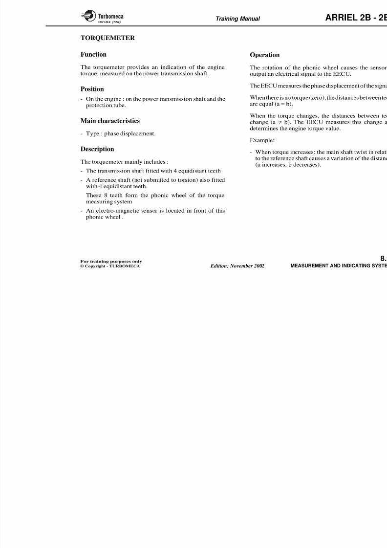
8/13/2019 Arriel_2B-2B1 11-02 En
http://slidepdf.com/reader/full/arriel2b-2b1-11-02-en 293/461
- Fuel flow control at start (limitation of t4.5 by means of the EECU)
Position
- In the system : connected to the indicator and the EECU
- On the engine : the probes (x8) are located around therear part of the turbine casing and each probe is securedby a bolt.
Main characteristics
- Type : Chromel - Alumel
- Quantity : 8 probes (16 thermocouples) in 2 harnesses.
Thus the t4.5 gas temperature measuretwo distinct measuring channels, eac
- 8 thermocouples, connected in paraindicating system
- 8 thermocouples, also connected inEngine Electronic Control Unit.
In fact, the system consists of 2 asseEach assembly is an LRU.
Principle of operation
A thermocouple produces an electromproportional to the temperature differand the cold junction.
This voltage is supplied, via the conf
- The EECU (for start fuel flow con
- The t4.5 indicator (millivoltmeter g
Celsius)
Training Manual ARR
PR(sheath an
Alumel
MOUNTING
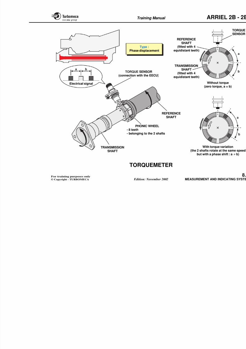
8/13/2019 Arriel_2B-2B1 11-02 En
http://slidepdf.com/reader/full/arriel2b-2b1-11-02-en 294/461
CONFORMATION
BOX
MOUNTINGFLANGE
(1 bolt)
Type :Chromel - Alumel
Quantity :
8 probes (16 thermocouples)in 2 harnesses
THERMOCOUPLEHARNESS (x2)
HARNESSES
EECU
t4 5 INDICATION
VEMD
Training Manual ARR
t4.5 CONFORMATION BOX
Function
The conformation box forms the interface between the
thermocouples, the indicator and the EECU.
It also allows a corrected temperature indication for a
Description
The t4.5 conformation box is mounte
output shaft protection tube.
The box is provided with:
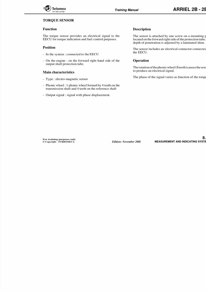
8/13/2019 Arriel_2B-2B1 11-02 En
http://slidepdf.com/reader/full/arriel2b-2b1-11-02-en 295/461
given turbine inlet temperature.
Being given discrepancies of measurement, theconformation ensures a reading which reflects a referencetemperature identical for all engines.
The conformation box is matched to the gas generator
module.
Position
- In the system : connected to the indicator and the EECU
- On the engine : on a support mounted underneath theoutput shaft protection tube.
Main characteristics
- Type : box with conformation resistors installed on aprinted circuit board
- Setting : adapted to the gas generator (M03 module).
The box is provided with:
- 5 electrical connectors :
• 2 harness connectors
• 2 EECU connectors
• 1 indicator connector
- Printed circuit board equipped wit
• 2 equal ZERO resistors
• 2 equal PENTE (slope) resisto
Operation
The t4.5 conformation box provides between the thermocouples, the EECIt contains resistors which enable a unfor a given turbine inlet temperature
The resistor values are matched with tare recorded on the module M03 log
Note : Theresistorscanbeadjustedb
Training Manual ARR
ZERO
C
Z P Z P
C
PENTE PENTEZERO
C ON T R OL
1
2
3
4
5
6
7
1
2
3
4
5
6
7
1
2
3
4
5
6
7
1
2
3
4
5
6
7
CONNECTIONS(adjustment of
resistors)
T
EECU
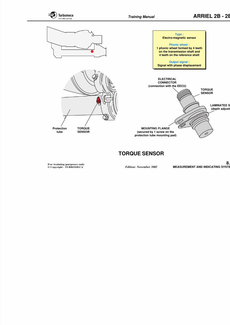
8/13/2019 Arriel_2B-2B1 11-02 En
http://slidepdf.com/reader/full/arriel2b-2b1-11-02-en 296/461
PENTE
ZERO
I N D I C A
T I O N
PENTE
ZERO
C O N T R O L
VEMD
Thermocoupleharness (x2)
EECUCONNECTOR
Mountingflange
RIGHT HARNESSCONNECTOR
Type :Box with
conformationresistors
Setting :
Adapted tothe gas generatormodule (M03)
t4.5INDICATION
Training Manual ARR
TORQUE MEASUREMENT AND
INDICATING SYSTEM
Function
The system provides measurement the engine torque,measured on the power transmission shaft.
General operation
The torquemeter measures the torqueAn electro-magnetic sensor transformelectrical signal
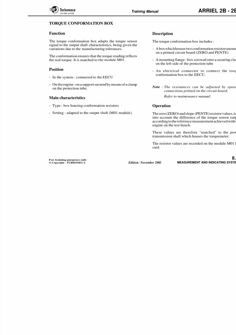
8/13/2019 Arriel_2B-2B1 11-02 En
http://slidepdf.com/reader/full/arriel2b-2b1-11-02-en 297/461
Position
All the system components are located on the engineexcept the EECU and the torque indicator.
Main characteristics- Type : phase displacement
- Torque sensor : electro-magnetic
Main components
- Power transmission and reference shafts
- Torque sensor
- Torque conformation box
- Engine Electronic Control Unit
- Torque indicator.
Description
electrical signal.
This signal is sent through the EECU tin the cockpit.
Note : The system includes resistconformation box) to obtainvalue.
Training Manual ARR
TORQSENS
PHASEDISPLACEMENT
TORQUEMETER
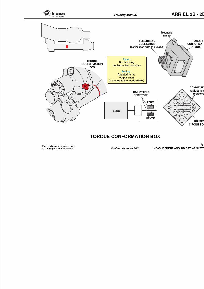
8/13/2019 Arriel_2B-2B1 11-02 En
http://slidepdf.com/reader/full/arriel2b-2b1-11-02-en 298/461
Type :Phase displacement
Torque sensor :
Electro magnetic
EECU
TORQUE
INDICATOR
TORQUE
CONFORMATIONBOX
POW
VEMD
Training Manual ARR
Operation
The rotation of the phonic wheel coutput an electrical signal to the EEC
The EECUmeasures the phase displac
TORQUEMETER
Function
The torquemeter provides an indication of the enginetorque, measured on the power transmission shaft.
8/13/2019 Arriel_2B-2B1 11-02 En
http://slidepdf.com/reader/full/arriel2b-2b1-11-02-en 299/461
The EECU measures the phase displac
When there is no torque (zero), the disare equal (a = b).
When the torque changes, the dista
change (a ≠ b). The EECU measudetermines the engine torque value.
Example:
- When torque increases: the main sto the reference shaft causes a varia(a increases, b decreases).
Position
- On the engine : on the power transmission shaft and theprotection tube.
Main characteristics- Type : phase displacement.
Description
The torquemeter mainly includes :
- The transmission shaft fitted with 4 equidistant teeth
- A reference shaft (not submitted to torsion) also fittedwith 4 equidistant teeth.
These 8 teeth form the phonic wheel of the torquemeasuring system
- An electro-magnetic sensor is located in front of thisphonic wheel .
Training Manual ARR
REFERENCESHAFT
(fitted with 4equidistant teeth)
Type :Phase displacement
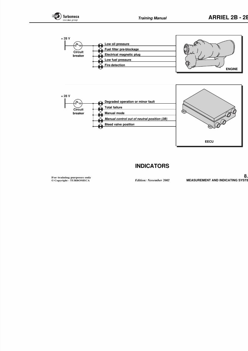
8/13/2019 Arriel_2B-2B1 11-02 En
http://slidepdf.com/reader/full/arriel2b-2b1-11-02-en 300/461
a
b
a b
Without(zero torq
With torq
TRANSMISSIONSHAFT
(fitted with 4equidistant teeth)
Electrical signal
REFERENCESHAFT
S SS O
TORQUE SENSOR(connection with the EECU)
PHONIC WHEEL- 8 teeth- belonging to the 2 shafts
Training Manual ARR
TORQUE SENSOR
Function
The torque sensor provides an electrical signal to theEECU for torque indication and fuel control purposes.
Description
The sensor is attached by one screwlocated on the forward right side of thdepth of penetration is adjusted by a
8/13/2019 Arriel_2B-2B1 11-02 En
http://slidepdf.com/reader/full/arriel2b-2b1-11-02-en 301/461
Position
- In the system : connected to the EECU
- On the engine : on the forward right hand side of theoutput shaft protection tube.
Main characteristics
- Type : electro-magnetic sensor
- Phonic wheel : 1 phonic wheel formed by 4 teeth on thetransmission shaft and 4 teeth on the reference shaft
- Output signal : signal with phase displacement.
The sensor includes an electrical conthe EECU.
Operation
The rotation of the phonic wheel (8 teeto produce an electrical signal.
The phase of the signal varies as fun
Training Manual ARR
Type :Electro-magnetic sensor
Phonic wheel :1 phonic wheel formed by 4 teeth
on the transmission shaft and
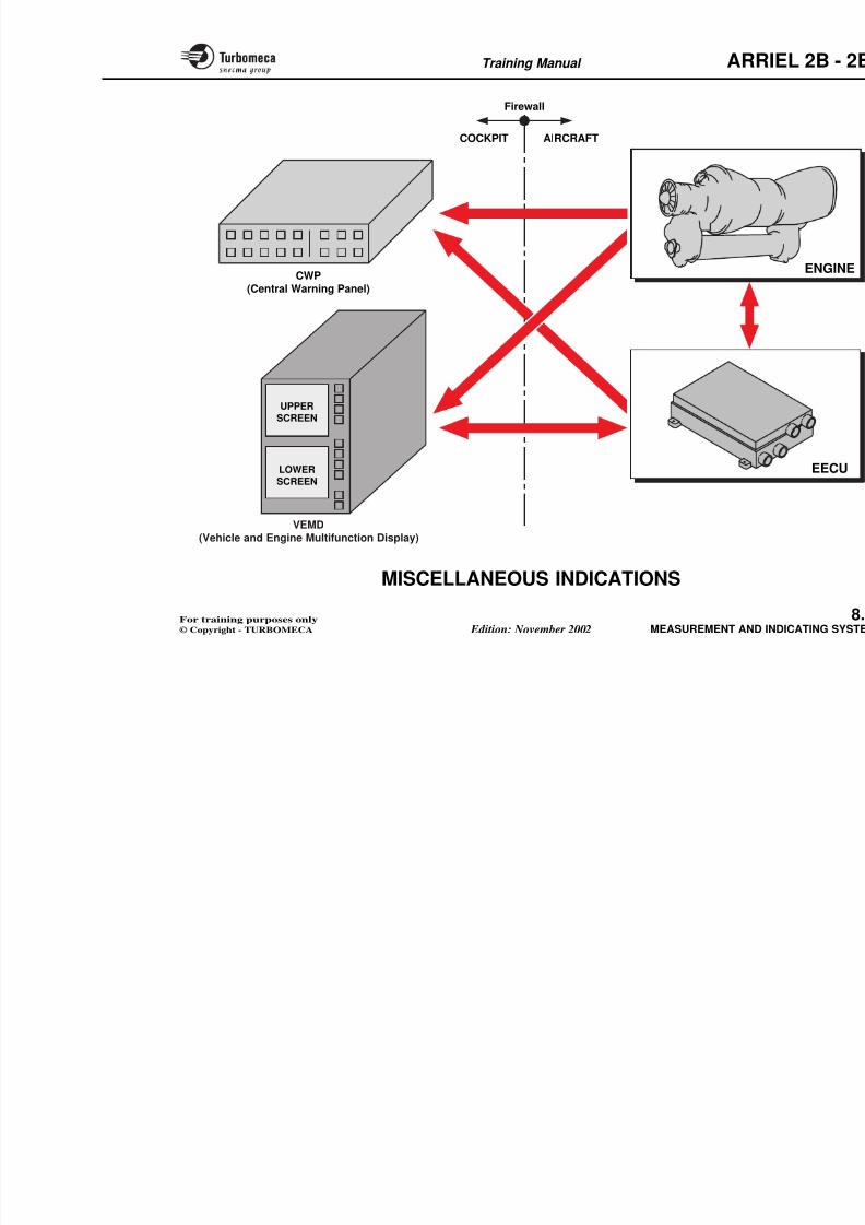
8/13/2019 Arriel_2B-2B1 11-02 En
http://slidepdf.com/reader/full/arriel2b-2b1-11-02-en 302/461
on the transmission shaft and4 teeth on the reference shaft
Output signal :Signal with phase displacement
MOUNTING FLANGE(secured by 1 screw on the
protection tube mounting pad)
ELECTRICALCONNECTOR
(connection with the EECU)
TOSE
TORQUESENSOR
Protectiontube
Training Manual ARR
Description
The torque conformation box includ
- A box which houses two conformaton a printed circuit board (ZERO
TORQUE CONFORMATION BOX
Function
The torque conformation box adapts the torque sensorsignal to the output shaft characteristics, being given thevariations due to the manufacturing tolerances.
8/13/2019 Arriel_2B-2B1 11-02 En
http://slidepdf.com/reader/full/arriel2b-2b1-11-02-en 303/461
on a printed circuit board (ZERO
- A mounting flange : box screwed oon the left side of the protection tu
- An electrical connector to co
conformation box to the EECU.
Note : The resistances can be adconnections printed on the ci
Refer to maintenance manua
OperationThe zero (ZERO) and slope (PENTEinto account the difference of the taccording to the reference measuremengine on the test bench.
These values are therefore "matctransmission shaft which houses the
The conformation ensures that the torque reading reflectsthe real torque. It is matched to the module M01.
Position
- In the system : connected to the EECU
- On the engine : on a support secured by means of a clampon the protection tube.
Main characteristics
- Type : box housing conformation resistors
- Setting : adapted to the output shaft (M01 module).
Training Manual ARR
Mountingflange
ELECTRICALCONNECTOR
( i i h h EECU)
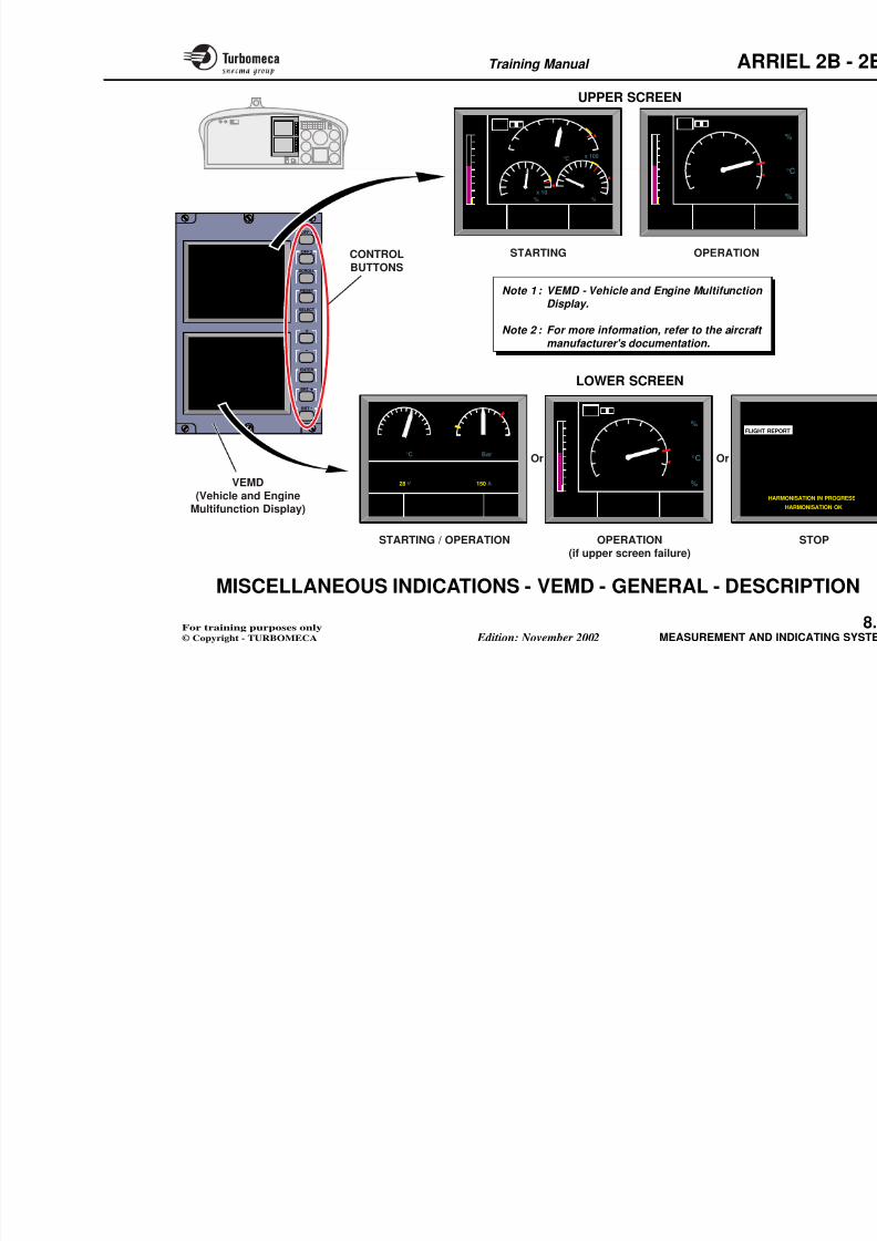
8/13/2019 Arriel_2B-2B1 11-02 En
http://slidepdf.com/reader/full/arriel2b-2b1-11-02-en 304/461
ZERO
PENTE
1 2 3
1 2 3
TORQUE
CONFORMATIONBOX
(connection with the EECU)
EECU
ZERO
PENTE
ADJUSTABLERESISTORS
Type :Box housing
conformation resistors
Setting :Adapted to the
output shaft(matched to the module M01)
Training Manual ARR
INDICATORS
There are several indicators which give information aboutthe engine operation. These pages summarize the variouslights which have already been dealt with in other chapters.
Position
Indications supplied through the
- Total failure
- Degraded operation or minor fault
- Manual mode
8/13/2019 Arriel_2B-2B1 11-02 En
http://slidepdf.com/reader/full/arriel2b-2b1-11-02-en 305/461
- On the instrument panel.
Main characteristics
- Indicators directly connected to the engine sensors
- Indicators whose signal is provided by the EECU.
Engine sensors connected direct to the cockpit
- Low oil pressure
- Fuel filter pre-blockage
- Electrical magnetic plug
- Low fuel pressure
- Fire detection.
- Manual mode
- Manual control out of neutral pos
- Bleed valve position.
Training Manual ARR
+ 28 V
Low oil pressure
Fuel filter pre-blockage
Electrical magnetic plugCircuitbreaker
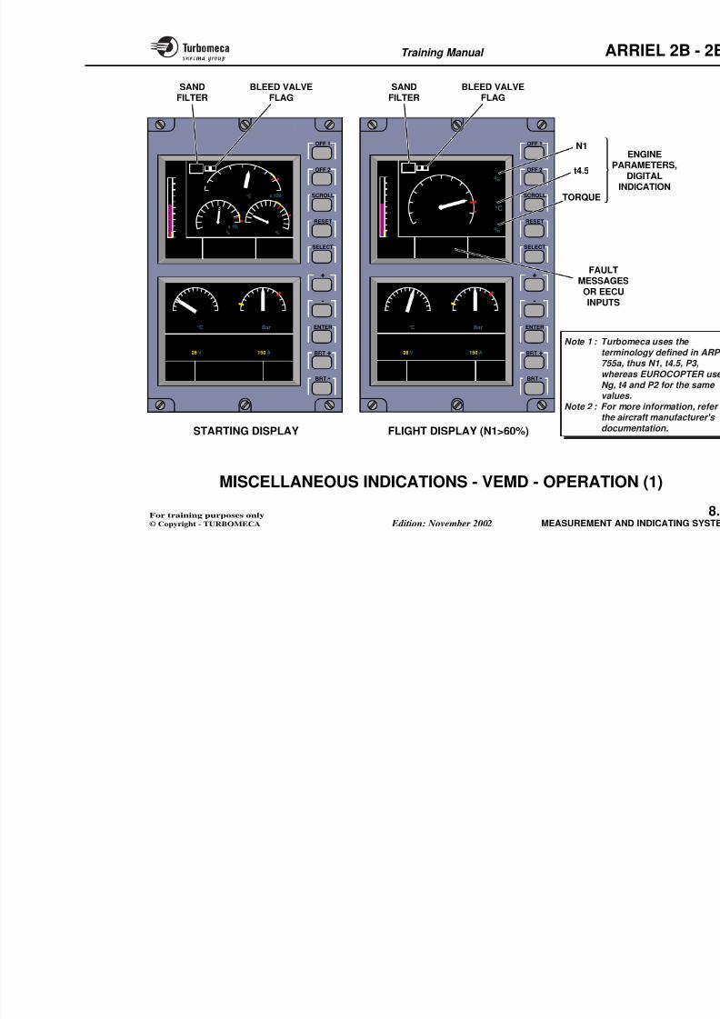
8/13/2019 Arriel_2B-2B1 11-02 En
http://slidepdf.com/reader/full/arriel2b-2b1-11-02-en 306/461
+ 28 V
EECU
g p g
Low fuel pressure
Fire detection
breaker
Circuit
breaker
Degraded operation or minor fault
Total failure
Manual mode
Bleed valve position
Manual control out of neutral position (2B)
Training Manual ARR
MISCELLANEOUS INDICATIONS
Function
To provide information in the cockpit about the operationof the aircraft and engine systems.
P iti
Description
There are two main indicating devic
- The VEMD - Vehicle and Engine M
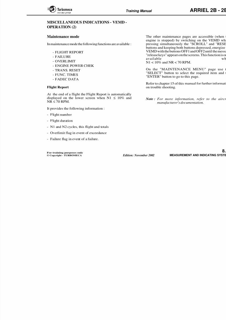
8/13/2019 Arriel_2B-2B1 11-02 En
http://slidepdf.com/reader/full/arriel2b-2b1-11-02-en 307/461
Position
- On the instrument panel.
Main characteristics
- Central Warning Panel
- Display unit with two screens
- Liquid crystal displays.
Main components
- Engine sensors
- EECU
- VEMD
- CWP.
- The CWP - Central Warning Pane
The VEMD displays all the necessarparameters. It can also display mainwhen the aircraft is on the ground. Itand lower screen and ten selector buttvarious functions.
The CWP has a set of warning lights tomalfunction in any helicopter vital s
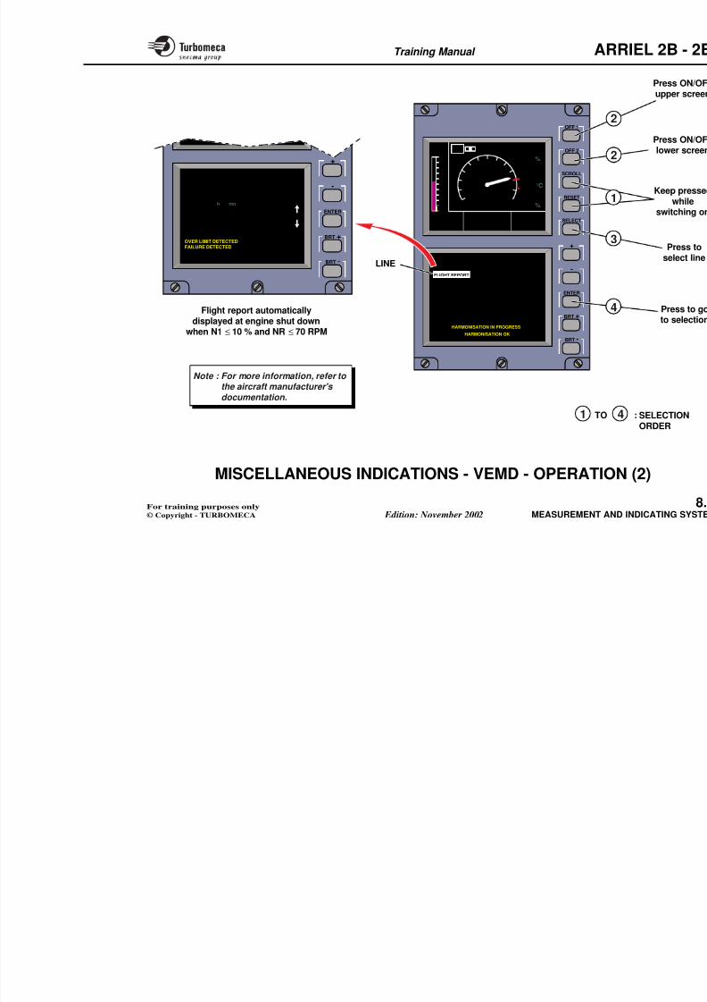
8/13/2019 Arriel_2B-2B1 11-02 En
http://slidepdf.com/reader/full/arriel2b-2b1-11-02-en 308/461
Training Manual ARR
MISCELLANEOUS INDICATIONS - VEMD -
GENERAL - DESCRIPTION
Function
To provide information in the cockpit about the operationof the aircraft and engine systems.
Description
The upper screen has two display mo
- Engine parameter screen in startin
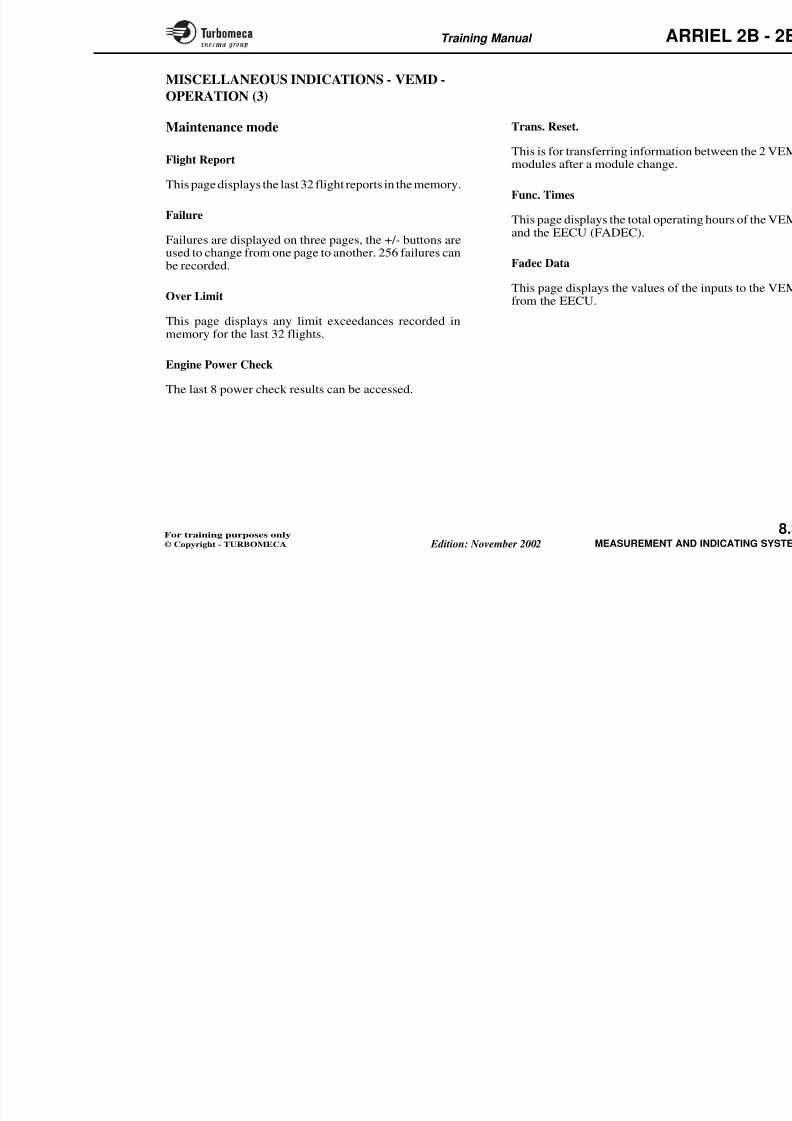
8/13/2019 Arriel_2B-2B1 11-02 En
http://slidepdf.com/reader/full/arriel2b-2b1-11-02-en 309/461
Position
- On the instrument panel.
Main characteristics
- 1 upper screen
- 1 lower screen
- Control buttons.
Engine parameter screen in startin
- Engine parameter screen in operat
The lower screen has three display m
- Operation screen in flight
- Engine parameter screen in operfailure)
- Maintenance screen (engine stopp
Note 1 :VEMD - Vehicle and En Display.
Note 2 : For more information, rmanufacturer's documenta
Training Manual ARR
F L I
768
9
10
11
5
P2
43
2
1
0
5
10 9
68
9
5
10
NG
T4
TQ
648 °C
61,8 % 72,7 %
5 64
3
0
78
9
x 100
x 10
2
0
4
10
8
6
-10
-5
5
0
P2
UPPER SCREEN
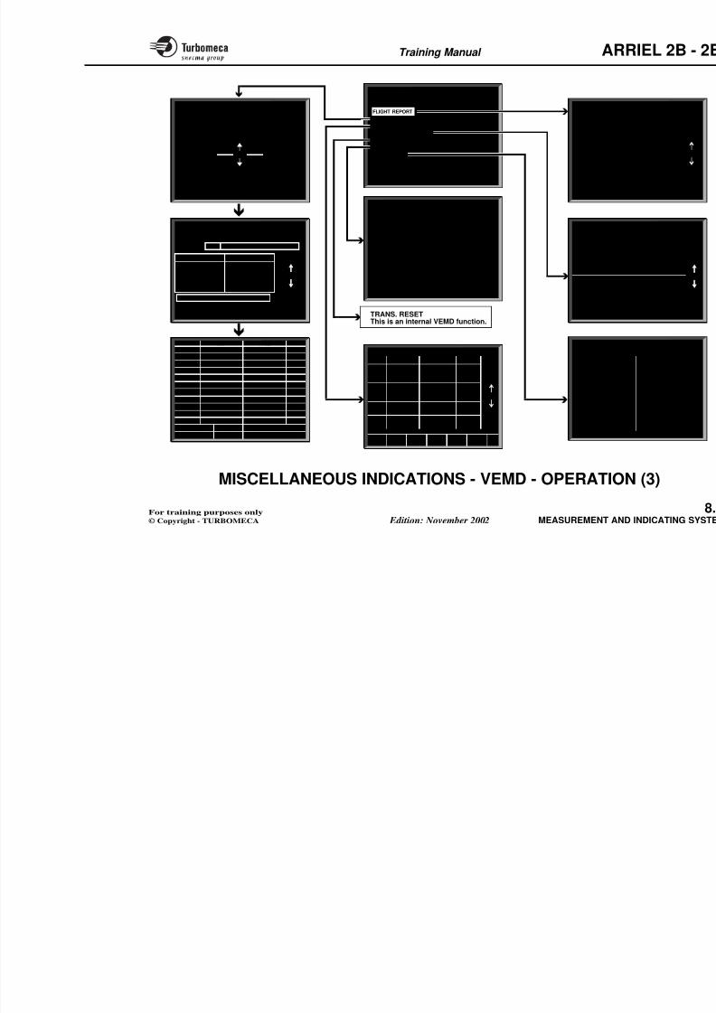
8/13/2019 Arriel_2B-2B1 11-02 En
http://slidepdf.com/reader/full/arriel2b-2b1-11-02-en 310/461
BRT -
BRT +
ENTER
-
+
SELECT
RESET
SCROLL
OFF 2
OFF 1
UPPER
SCREEN
LOWER
SCREEN
F L I
MESSAGES
768
9
10
11
5
P2
43
2
1
0
0
5
10
NG
98 %
T4
680 °C
TQ
90 %
MESSAGES
0 0, % , %
FLIGHT REP
FAILURE
OVER LIMIT
ENGINE PO
TRANS. RE
FUNC. TIME
FADEC DAT
HA
5 10
160
TEMP90 °C
x 10
68
102
4
0
PRESS6 Bar
U/BUS28 V
I/GEN150 A
16
ENG OIL
LOWER SCREEN
STARTING OPERATIONCONTROL
BUTTONS
Note 1 : VEMD - Vehicle and Engine MultifunctionDisplay.
Note 2 : For more information, refer to the aircraft
manufacturer's documentation.
VEMD
(Vehicle and EngineMultifunction Display)
Or Or
Training Manual ARR
MISCELLANEOUS INDICATIONS - VEMDOPERATION (1)
There are two operating modes: operational andmaintenance.
Operational mode
In this mode in normal operation there are two displays
Flight Display
• Upper Screen: FLI
FLI means First Limit Indicator. This graduated from 0 to 11. The needlepositioned as a function of the param
8/13/2019 Arriel_2B-2B1 11-02 En
http://slidepdf.com/reader/full/arriel2b-2b1-11-02-en 311/461
In this mode, in normal operation, there are two displayspossible - starting display and flight display.
Starting Display
• Upper Screen: "3 info display"
- t4.5 analog and digital- Delta N1 analog- N1 digital- Tq analog and digital- Bleed valve flag- P2 (sand filter)- OAT digital- Fuel quantity analog and digital
• Lower Screen- Eng oil pressure analog and digital- Eng oil temp. analog and digital- Starter current digital- Main Bus volts digital- Fuel quantity digital- Flight time remaining digital
Th di l h t ti ll t th fli ht di l t
positioned as a function of the paramits limit. The parameters used are N1needle reaches 10 one of the paramelimit. There is a digital indication of eright of the FLI indicator. When a paits limit a yellow line will flash undewhen it reaches the limit the line becowarning sounds.
• Lower Screen
Same indication as in start displaycurrent is replaced by generator curr
At the bottom of the screen is an areThe EECU inputs to the VEMD maythis area by pressing "SELECT".
Note 1 : TURBOMECA uses the ter ARP 755a, thus N1, t EUROCOPTER uses Ng, t4values.
N t 2 F i f ti
Training Manual ARR
OFF 1
P2
OFF 1
P2
BLEED VALVEFLAG
SANDFILTER
BLEED VALVEFLAG
SANDFILTER
N1EN
PARA
8/13/2019 Arriel_2B-2B1 11-02 En
http://slidepdf.com/reader/full/arriel2b-2b1-11-02-en 312/461
BRT -
BRT +
ENTER
-
+
SELECT
RESET
SCROLL
OFF 2
5 10
160
TEMP
90 °C
x 10
68
102
4
0
PRESS
6 Bar
U/BUS28 V
I/GEN150 A
16
ENG OIL
F L I
MESSAGES
768
9
10
11
5
P2
43
2
10
0
5
10
NG
98 %
T4
680 °C
TQ
90 %
BRT -
BRT +
ENTER
-
+
SELECT
RESET
SCROLL
OFF 2
5 10
160
TEMP
90 °C
x 10
68
102
4
0
PRESS
6 Bar
U/BUS28 V
I/GEN150 A
16
ENG OIL
0
5
10
NG
T4
TQ
648 °C
61,8 % 72,7 %
5 64
3
0
78
9
x 100
x 10
2
0
4
10
86
-10
-5
5
0
P2
S G S G S
FAULTMESSAGESOR EECUINPUTS
t4.5
TORQUE
PARADIG
INDI
Note 1 : Turbome
terminol755a, thu
whereasNg, t4 an
values.Note 2 : For more
the aircr
d
Training Manual ARR
MISCELLANEOUS INDICATIONS - VEMD -
OPERATION (2)
Maintenance mode
In maintenance mode the following functions are available :
- FLIGHT REPORT
The other maintenance pages are aengine is stopped) by switching onpressing simultaneously the "SCRObuttons and keeping both buttons depVEMD with the buttons OFF1 and OF
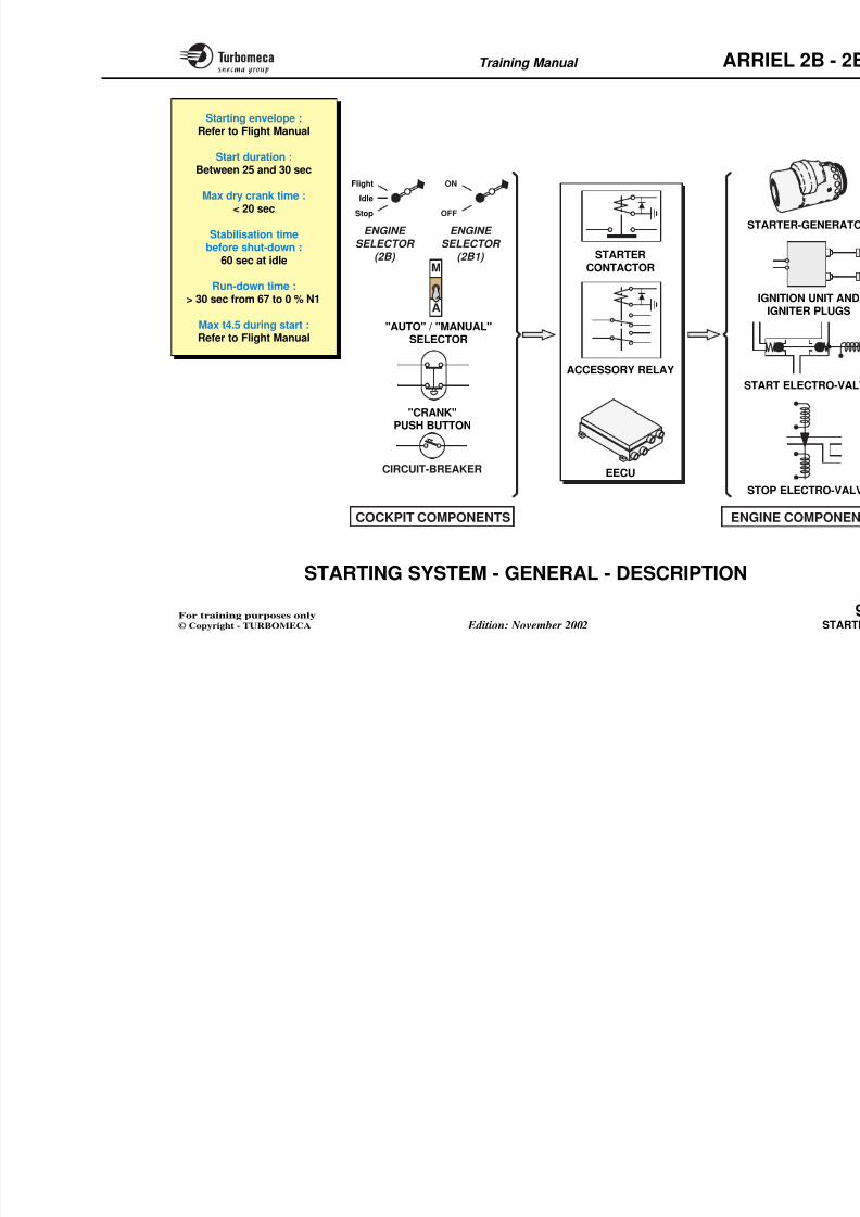
8/13/2019 Arriel_2B-2B1 11-02 En
http://slidepdf.com/reader/full/arriel2b-2b1-11-02-en 313/461
- FLIGHT REPORT
- FAILURE
- OVERLIMIT
- ENGINE POWER CHEK
- TRANS. RESET
- FUNC. TIMES
- FADEC DATA
Flight Report
At the end of a flight the Flight Report is automaticallydisplayed on the lower screen when N1 ≤ 10% and
NR≤ 70
RPM.
It provides the following information :
- Flight number
- Flight duration
- N1 and N2 cycles, this flight and totals
O li it fl i t f d
"release keys" appears on the screens.available N1 < 10% and NR < 70 RPM.
On the "MAINTENANCE MEN
"SELECT" button to select the req"ENTER" button to go to this page.
Refer to chapter 15 of this manual foon trouble shooting.
Note : For more information, ref
manufacturer's documentatio
Training Manual ARR
OFF 2
OFF 1
765
P2
10
NG
98 %
+
2
2
8/13/2019 Arriel_2B-2B1 11-02 En
http://slidepdf.com/reader/full/arriel2b-2b1-11-02-en 314/461
BRT -
BRT +
ENTER
-
+
SELECT
RESET
SCROLL
F L I
MESSAGES
768
9
10
11
54
32
10
0
5
T4
680 °C
TQ
90 %
MAINTENANCE MENU
FLIGHT REPORT
FAILURE
OVER LIMIT
ENGINE POWER CHECK
TRANS. RESET
FUNC. TIMES
FADEC DATA
HARMONISATION IN PROGRESS
HARMONISATION OK
BRT -
BRT +
ENTER
-
FLIGHT REPORT
FLIGHT NUMBER 452
DURATION 1 h 21 mn
CYCLE NG XX.XX I XXXX.XXCYCLE NF XX.XX I XXXX.XX
TOTAL
OVER LIMIT DETECTEDFAILURE DETECTED
EXIT ---> PRESS RESET
Pg
-
+
31
1
3
4
1 4TO
Flight report automatically
displayed at engine shut downwhen N1 ≤ 10 % and NR ≤ 70 RPM
LINE
Note : For more information, refer tothe aircraft manufacturer's
documentation.
Training Manual ARR
MISCELLANEOUS INDICATIONS - VEMD -
OPERATION (3)
Maintenance mode
Flight Report
This page displays the last 32 flight reports in the memory
Trans. Reset.
This is for transferring information bmodules after a module change.
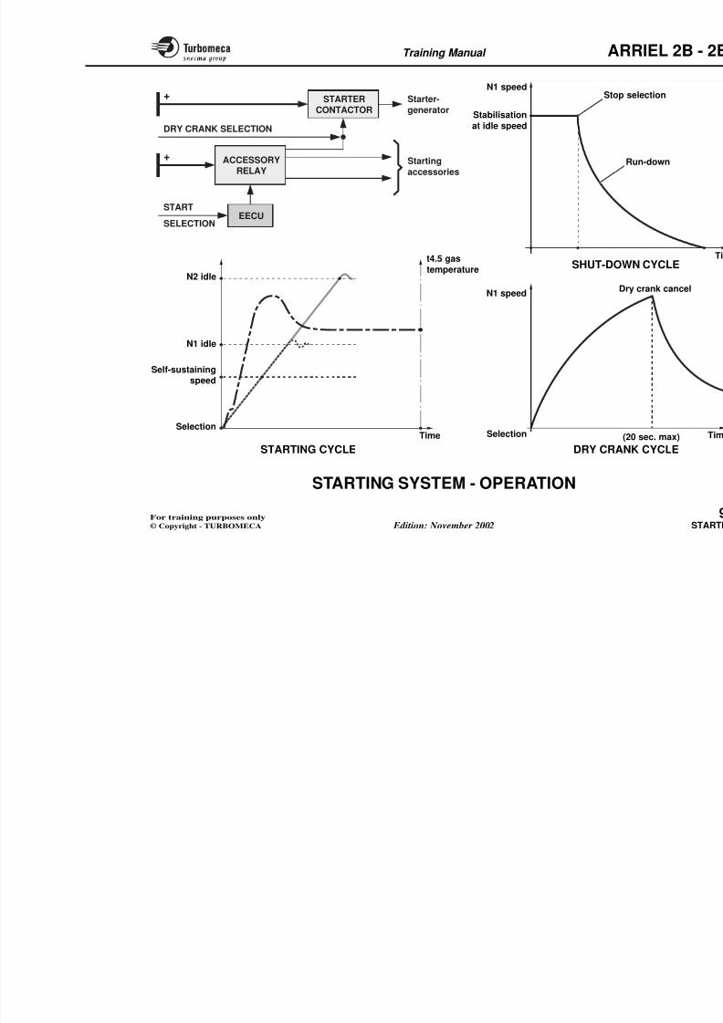
8/13/2019 Arriel_2B-2B1 11-02 En
http://slidepdf.com/reader/full/arriel2b-2b1-11-02-en 315/461
This page displays the last 32 flight reports in the memory.
Failure
Failures are displayed on three pages, the +/- buttons are
used to change from one page to another. 256 failures canbe recorded.
Over Limit
This page displays any limit exceedances recorded inmemory for the last 32 flights.
Engine Power Check
The last 8 power check results can be accessed.
Func. Times
This page displays the total operatingand the EECU (FADEC).
Fadec Data
This page displays the values of the from the EECU.
Training Manual ARR
FLIGHT
FLIGHT NUMBER 452
DURATION 1 h 21 mn
CYCLE NG XX.XX I XCYCLE NF XX.XX I X
FLIGHT XXXXX
FLIGHTXXXXX
Nb FAILXXX
FAILURE DIAGNOSIS
MAINTENANCE MENU
FLIGHT REPORT
FAILURE
OVER LIMIT
ENGINE POWER CHECKTRANS. RESET
FUNC. TIMES
FADEC DATA
XXX
XXX
8/13/2019 Arriel_2B-2B1 11-02 En
http://slidepdf.com/reader/full/arriel2b-2b1-11-02-en 316/461
FAIL
OVER LIMIT DETECTEDFAILURE DETECTED
EXIT ---> P
ENGINE POW
NG XXX.X
t4 XXX
TRQ XXX.X
t4 MARGIN
- XXX
GOOD
FADEC
NG TOP XXX.X %NG MCP XXX.X %NG LIM XXX.X %t4 - XXX °CIAS XXX Km/hTRIM NF XXX.X %COL. PITCH XXX.X %P3 XX.XX barFF XXX l/h
BV/HSPD/IRS
OVERT LIMIT XXXXX
TIME
TRQ
NG
NF
LIMIT MAX
FUNCTIONAL TIMES
FADEC FUNC. TIMES :
FADEC ENG. FUNC. TIMES :
MODULE 1 FLIGHT TIMES :
MODULE 1 FUNC. TIMES :
MODULE 2 FLIGHT TIMES :
MODULE 2 FUNC. TIMES :
XXXXX h
XXXXX h
XXXXX h
XXXXX h
XXXXX h
XXXXX h
EXIT ---> PRESS RESET
Pg
-
+
XX
31
XXXXXX
XXXXXXX
XX
t4 XXXXXX
XXXXXXX
XX
XXXXXX
XXXX
XXXXXX
) TRQ MED XXX X) TRQ EXT
) TRQ TRA
) T4 MED) T4 HI
XXXXXX
) T4 LOW
) NG TRA) NG MNT
) NF EXT) NF TRA
XXX
XXXXXXX
EXIT ---> P
COMPLETE DIAGNOSIS
FAIL on FLIGHT XXXXX at X XX XX
TEST REF
HARMONISATION IN PROGRESS
HARMONISATION OK
XX
NG
TRQ
t4
T4R1
T4R2
P0
OAT
GENC
GENV
NF
NR
XXX.X
XXX.X
XXX
XXXX.X
XXXX.X
XXXXX
XX.X
XXX
XX.X
XXXXX
XXX
XXX.X
XXX.X
XXX
XXXX.X
XXXX.X
XXXXX
XX.X
XXX
XX.X
XXXXX
XXX
XXX
Param EOP
To see param press ENTER
EXIT ---> PRESS RESET
EXIT ---> PRESS RESET
FAIL
1
-
+
XXX
XXX
P
EOPFAIL
LRU name LRU name
XXXXXXXXXXXXXXXXXXXXXXXXXXXXXXXXXXXXXXXXXXXXXXXXXXXXXXXXXXXXXXXXX
XXXXXXXXXXXXXXXXXXXXXXXXXXXXXXXXXXXXXXXXXXXXXXXXXXXX
1
TRANS. RESETThis is an internal VEMD function.
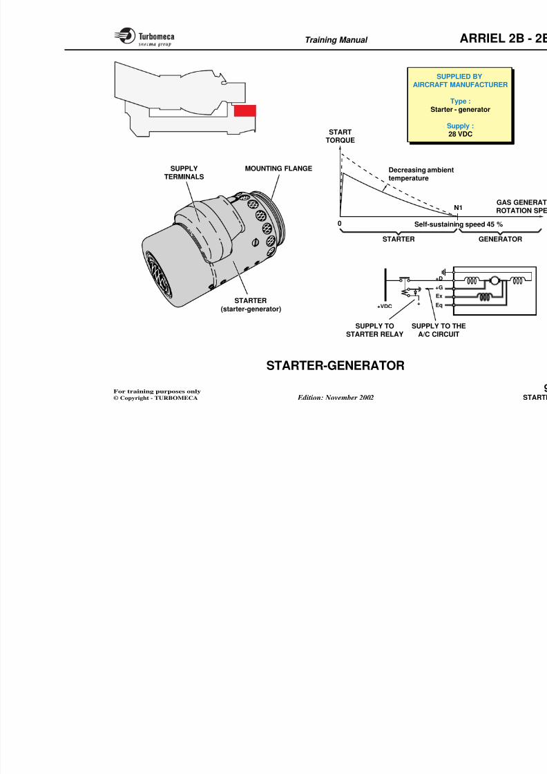
8/13/2019 Arriel_2B-2B1 11-02 En
http://slidepdf.com/reader/full/arriel2b-2b1-11-02-en 317/461
Training Manual ARR
9-STARTING
8/13/2019 Arriel_2B-2B1 11-02 En
http://slidepdf.com/reader/full/arriel2b-2b1-11-02-en 318/461
- Starting system ............................................................. 9
- Starter-generator ........................................................... 9
- Ignition system (74-00-00)............................................. 9
- Ignition unit (74-11-10) ................................................. 9
- Ignition cables (74-24-10).............................................. 9
- Igniter plugs (72-43-00) ................................................. 9
Training Manual ARR
Main components
- In the cockpit:
• Stop/Idle/Flight selector (2B)
• On/Off (2B1)
• Auto/Manual selector
STARTING SYSTEM - GENERAL -
DESCRIPTION
Function
The starting system ensures starting (on the ground and inflight) and dry crank of the engine. It includes the followingfunctions : cranking, fuel supply, ignition and sequential
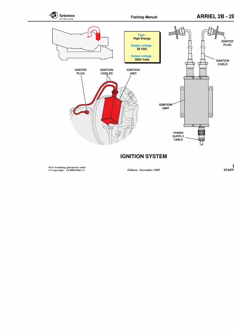
8/13/2019 Arriel_2B-2B1 11-02 En
http://slidepdf.com/reader/full/arriel2b-2b1-11-02-en 319/461
• Auto/Manual selector
• Crank push button
• Circuit breakers
- In the aircraft:
• Starter contactor• Accessory relay
• EECU
- On the engine:
• Starter generator
• Ignition system
• Start electro-valve• Stop electro-valve.
control.
Position
All the starting accessories are installed on the engineexcept the EECU which is installed in the aircraft. Indicatingand control components are aircraft components.
Main characteristics
- Starting envelope : refer to flight manual
- Start duration : between 25 and 30 sec
- Max dry crank time : < 20 sec
- Stabilisation time before shut-down : 60 sec at idle
- Run-down time : > 30 sec from 67 to 0 % N1
- Max t4.5 during start : refer to flight manual.
Training Manual ARR
Flight
Idle
ON
Starting envelope :Refer to Flight Manual
Start duration :Between 25 and 30 sec
Max dry crank time :
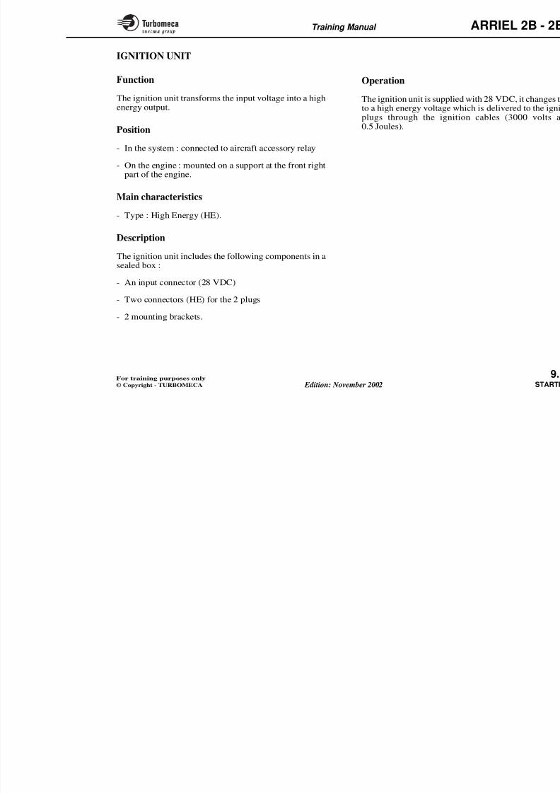
8/13/2019 Arriel_2B-2B1 11-02 En
http://slidepdf.com/reader/full/arriel2b-2b1-11-02-en 320/461
A
M
ST
ACCESSORY RELAY
STARTERCONTACTOR
EECU
I
STA
ST
"CRANK"PUSH BUTTON
CIRCUIT-BREAKER
ENGINE
SELECTOR (2B)
ENGINE
SELECTOR (2B1)
"AUTO" / "MANUAL"SELECTOR
Stop OFF< 20 sec
Stabilisation timebefore shut-down :
60 sec at idle
Run-down time :> 30 sec from 67 to 0 % N1
Max t4.5 during start :Refer to Flight Manual
Training Manual ARR
STARTING SYSTEM - OPERATION
This section deals with operating sequences associatedwith the starting system : start, shut-down and dry crank.
Starting cycle
The starting cycle is characterised by the evolution of theengine parameters especially the rotation speed and the
Dry crank cycle
A dry crank consists of cranking th
without supplying fuel or ignition (drycooling the engine or for maintenanc
The dry crank cycle comprises the fo
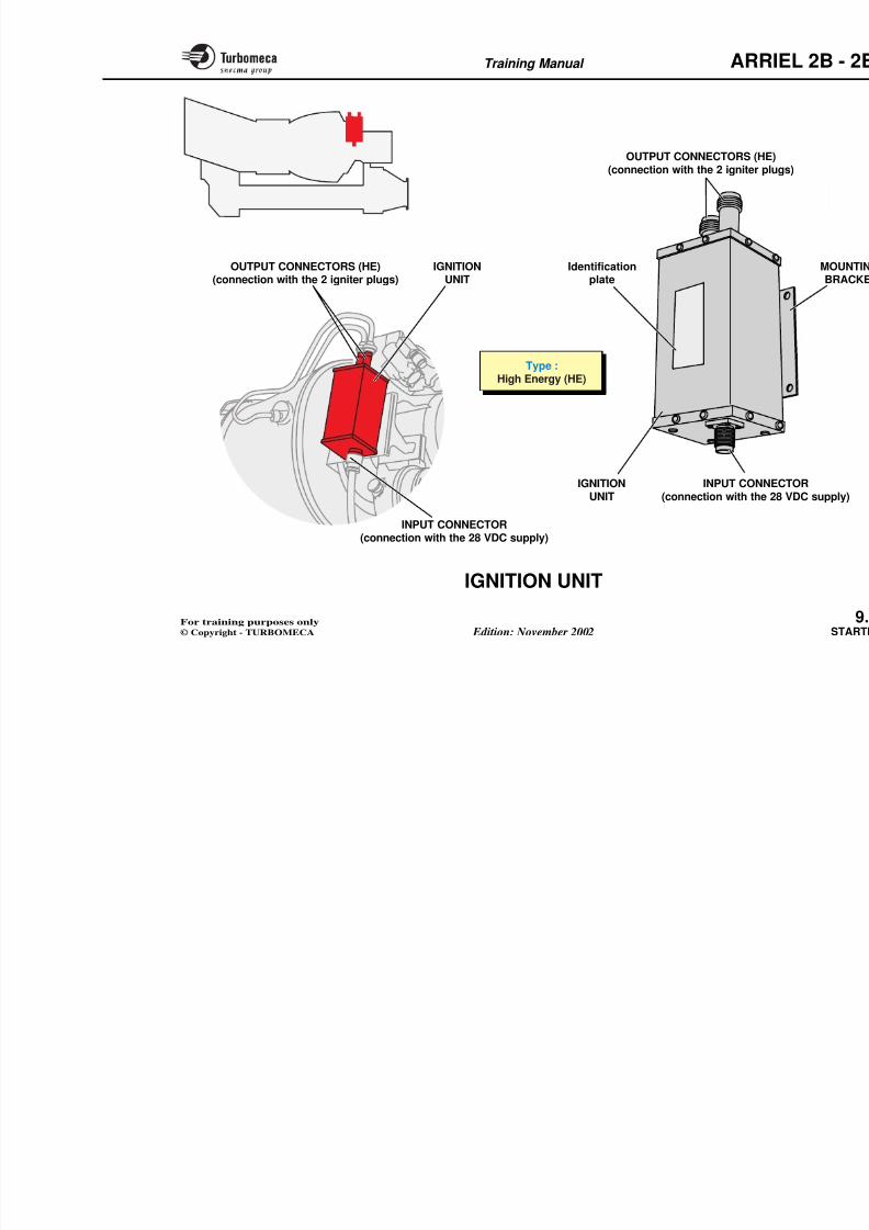
8/13/2019 Arriel_2B-2B1 11-02 En
http://slidepdf.com/reader/full/arriel2b-2b1-11-02-en 321/461
engine parameters, especially the rotation speed and thegas temperature.
The main points of the starting cycle are :
- Start selection
- Self-sustaining speed (de-energisation of the starter andignition unit)
- End of start (stabilisation at idle speed).
Shut-down cycle
This cycle comprises the following points :
- Stabilisation at idle speed
- Stop selection
- Run-down and stop.
- Dry crank selection
- Cranking of the rotating assembly
- End of dry crank and run-down.
Note : Dry crank time is limited overheating of the starter mo
Training Manual ARR
ACCESSORYRELAY
STARTERCONTACTOR
Starting
accessories
Starter-
generator
DRY CRANK SELECTION
+
+
N1 speedStop sel
Run
Stabilisation
at idle speed
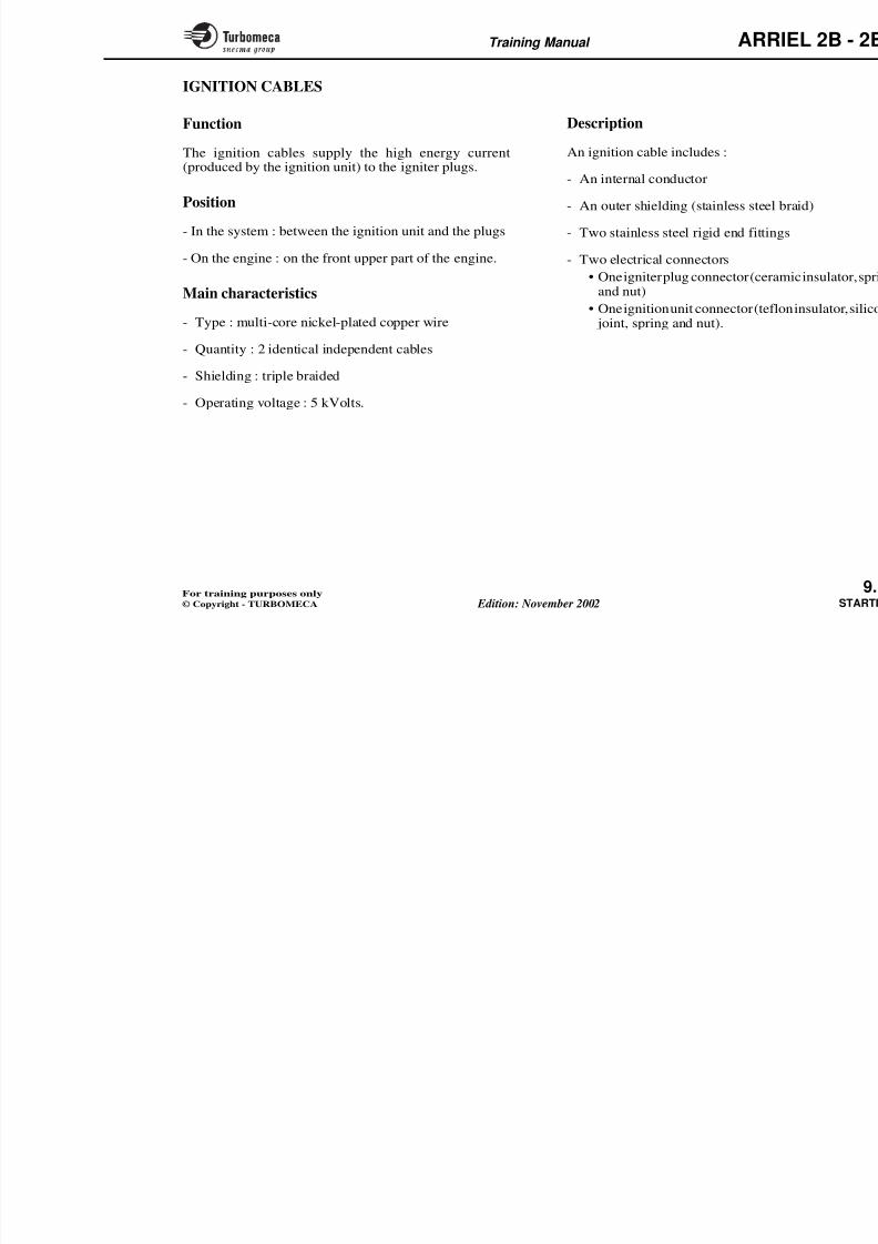
8/13/2019 Arriel_2B-2B1 11-02 En
http://slidepdf.com/reader/full/arriel2b-2b1-11-02-en 322/461
EECU
RELAY accessories
START
SELECTION
N2 idle
N1 idle
Self-sustainingspeed
S l i
t4.5 gas
temperature SHUT-DOWN
N1 speedDry c
Training Manual ARR
STARTER-GENERATOR
Function
The starter motor cranks the gas generator rotating assembly
during starting and dry crank.
At the end of starting and when the rotation speed issufficient thestarteroperatesasaDirectCurrentgenerator
Operation
Engine cranking (starter)
When "START" is selected the starterconnects the aircraft DC bus bar to t
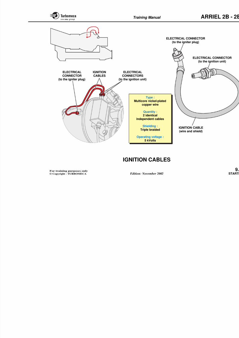
8/13/2019 Arriel_2B-2B1 11-02 En
http://slidepdf.com/reader/full/arriel2b-2b1-11-02-en 323/461
sufficient, the starter operates as a Direct Current generator.
Position
- On the engine : on the front face of the accessory
gearbox.
Main characteristics
- Supplied by aircraft manufacturer
- Type : starter-generator
- Supply : 28 VDC.
Description
The starter main components are :
- The starter (starter-generator)
h i fl
The starter then cranks the rotating aaccessory drive train.
The torque on the starter shaft is inve
the gas generator speed and will batmospheric temperature is low.
The N1 increases up to self-sustainwhich point the torque becomes negthe starter is cut by the opening of th
Generator operation
When self-sustaining speed is reachoperates as an electrical DC generaaircraft electrical system.
Training Manual ARR
SUPPLIED BYAIRCRAFT MANUFAC
Type :Starter - generat
Supply :28 VDCSTART
8/13/2019 Arriel_2B-2B1 11-02 En
http://slidepdf.com/reader/full/arriel2b-2b1-11-02-en 324/461
0
N1
+VDC Eq
Ex
+D
+G
+
SUPPLY
TERMINALS
STARTER(starter-generator)
MOUNTING FLANGE
28 VDC
OO
STARTTORQUE
Decreasing ambient
temperature
Self-sustaining speed
GSTARTER
Training Manual ARR
IGNITION SYSTEM
Function
This system ensures the ignition of the fuel sprayed by the
start injectors into the combustion chamber.
Position
Operation
The system is electrically energised fr
until self-sustaining speed is reached
During this period sparks are proelectrodes of the igniter plugs.
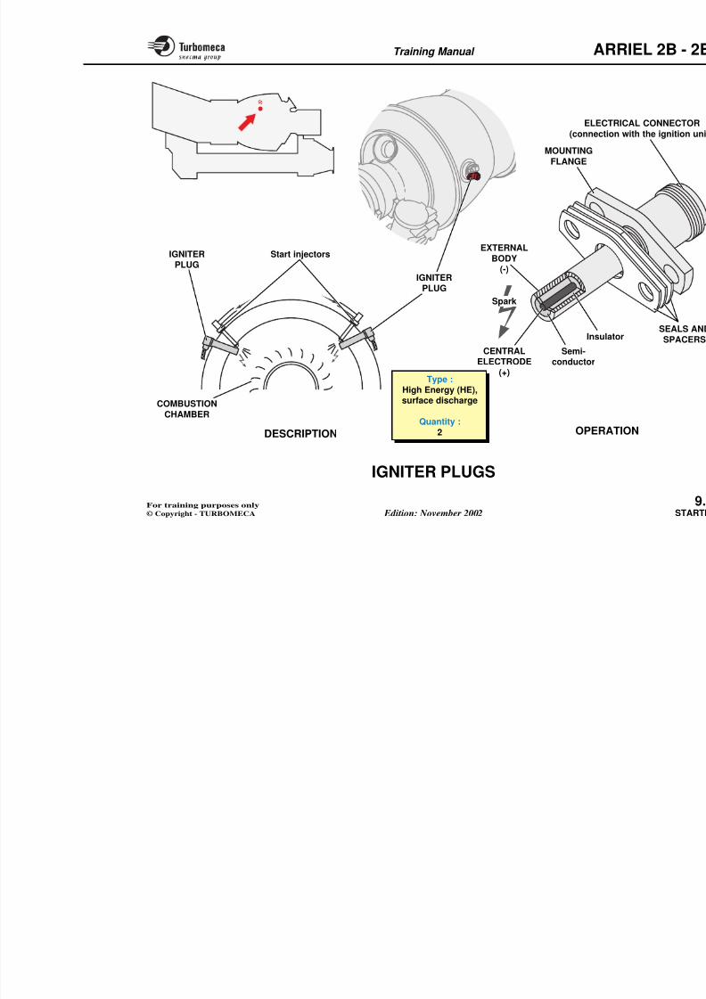
8/13/2019 Arriel_2B-2B1 11-02 En
http://slidepdf.com/reader/full/arriel2b-2b1-11-02-en 325/461
All the ignition system components are installed on theengine, except the electrical supply circuit.
Main characteristics
- Type : High Energy (HE)
- Supply voltage : 28 VDC.
Description
The ignition system includes the following components :
- 1 double ignition unit
- 2 ignition cables
- 2 igniter plugs.
g p g
Training Manual ARR
Type :High Energy
Supply voltage :28 VDC
Output voltage :
8/13/2019 Arriel_2B-2B1 11-02 En
http://slidepdf.com/reader/full/arriel2b-2b1-11-02-en 326/461
IGNITIONUNIT
IGNITIONCABLES
IGNITERPLUG
IGNITION
UNIT
POWER
SUPPLY
Output voltage :
3000 Volts
Training Manual ARR
IGNITION UNIT
Function
The ignition unit transforms the input voltage into a high
energy output.
Position
Operation
The ignition unit is supplied with 28
to a high energy voltage which is deplugs through the ignition cable0.5 Joules).
8/13/2019 Arriel_2B-2B1 11-02 En
http://slidepdf.com/reader/full/arriel2b-2b1-11-02-en 327/461
- In the system : connected to aircraft accessory relay
- On the engine : mounted on a support at the front rightpart of the engine.
Main characteristics
- Type : High Energy (HE).
Description
The ignition unit includes the following components in asealed box :
- An input connector (28 VDC)
- Two connectors (HE) for the 2 plugs
- 2 mounting brackets.
Training Manual ARR
OUTPUT CONNECTORS (HE(connection with the 2 igniter p
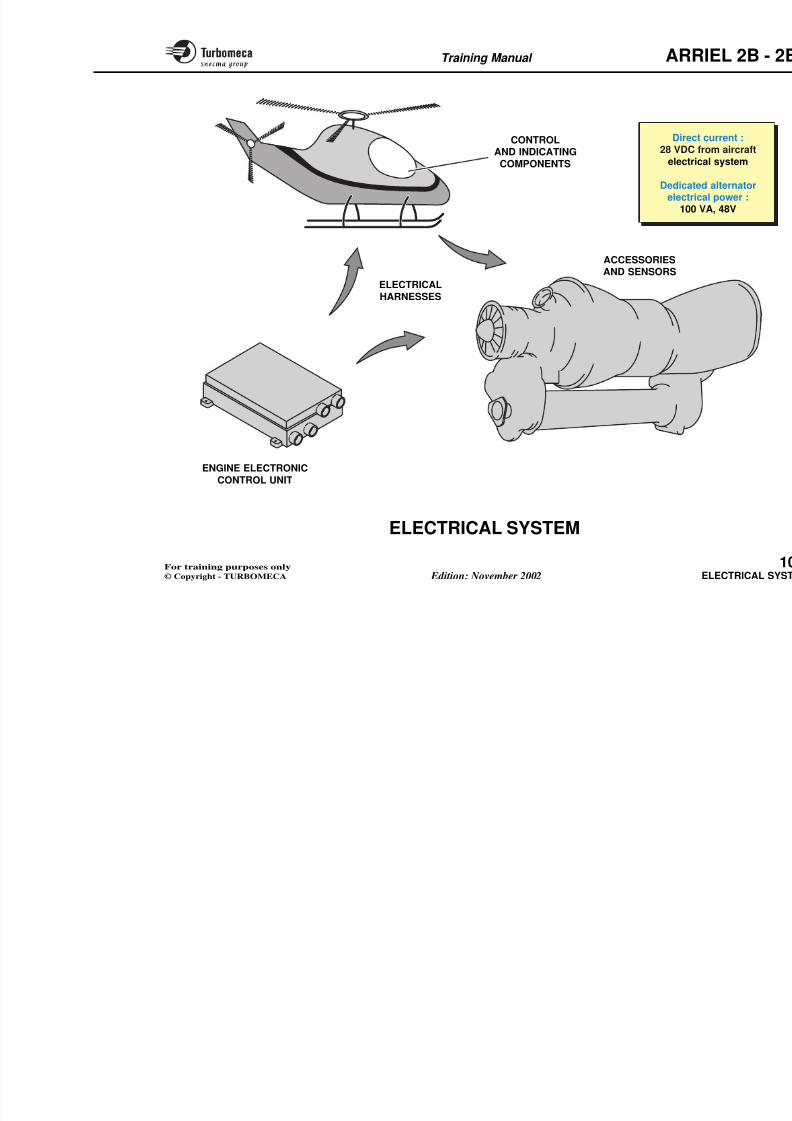
8/13/2019 Arriel_2B-2B1 11-02 En
http://slidepdf.com/reader/full/arriel2b-2b1-11-02-en 328/461
Type :High Energy (HE)
INPUT CONN(connection with the
IGNITIONUNIT
Identification
plate
OUTPUT CONNECTORS (HE)
(connection with the 2 igniter plugs)
IGNITION
UNIT
Training Manual ARR
IGNITION CABLES
Function
The ignition cables supply the high energy current
(produced by the ignition unit) to the igniter plugs.
Position
Description
An ignition cable includes :
- An internal conductor
- An outer shielding (stainless steel
8/13/2019 Arriel_2B-2B1 11-02 En
http://slidepdf.com/reader/full/arriel2b-2b1-11-02-en 329/461
- In the system : between the ignition unit and the plugs
- On the engine : on the front upper part of the engine.
Main characteristics
- Type : multi-core nickel-plated copper wire
- Quantity : 2 identical independent cables
- Shielding : triple braided
- Operating voltage : 5 kVolts.
- Two stainless steel rigid end fittin
- Two electrical connectors
• One igniter plug connector (ceraand nut)
• One ignition unit connector (tefl joint, spring and nut).
Training Manual ARR
ELECTRICAL
ELECTRICAL CONNECTOR(to the igniter plug)
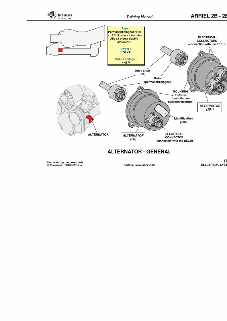
8/13/2019 Arriel_2B-2B1 11-02 En
http://slidepdf.com/reader/full/arriel2b-2b1-11-02-en 330/461
ELECTRICAL(to the ign
ELECTRICALCONNECTORS
(to the ignition unit)
IGNITION CABLE(wire and shield)
ELECTRICALCONNECTOR
(to the igniter plug)
IGNITIONCABLES
Type :Multicore nickel-plated
copper wire
Quantity :2 identical
independent cables
Shielding :Triple braided
Operating voltage :
Training Manual ARR
IGNITER PLUGS
Function
The igniter plugs produce sparks to ignite the fuel sprayed
by the start injectors.
Position
Description
An igniter plug comprises :
- An external body connected to the
- A semi-conductor fitted in the tip
8/13/2019 Arriel_2B-2B1 11-02 En
http://slidepdf.com/reader/full/arriel2b-2b1-11-02-en 331/461
- In the system : at the end of each igniter cable
- On the engine : mounted beside the start injectors oneither side of the combustion chamber casing.
Main characteristics
- Type : High Energy (HE), surface discharge
- Quantity : 2.
- An insulator
- A central electrode connected to th
- An electrical connector for conneunit
- Mounting flange (2 bolts on the po
- Seals and spacers (depth adjustme
Operation
The high energy current produced bsupplied to the central electrode ofdischarges, across the semi-conductcausing a powerful spark.
This spark ignites the air fuel mixtucombustion chamber by the two star
Training Manual ARR
MOUNTING
FLANGE
ELECTRIC
(connection w
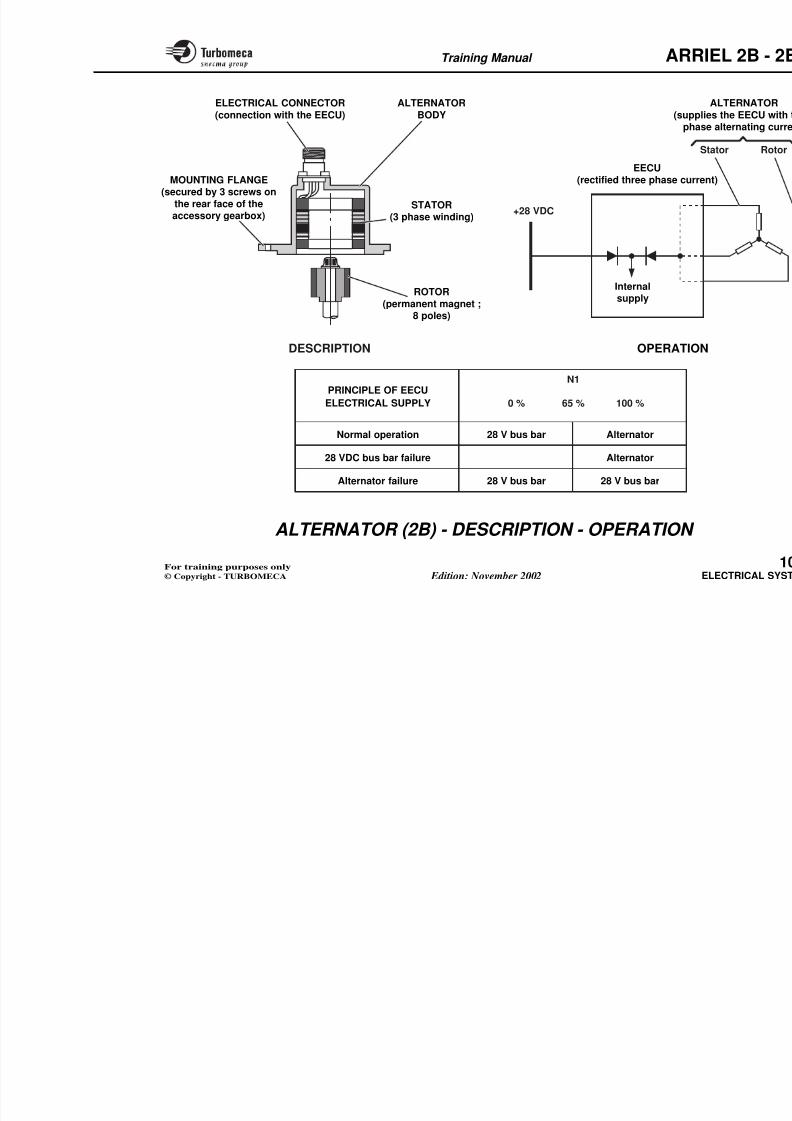
8/13/2019 Arriel_2B-2B1 11-02 En
http://slidepdf.com/reader/full/arriel2b-2b1-11-02-en 332/461
Semi-conductor
Insulator
EXTERNAL
BODY(-)
CENTRALELECTRODE
(+)
Spark
Start injectors
IGNITERPLUG
COMBUSTION
IGNITERPLUG
Type :High Energy (HE),surface discharge
8/13/2019 Arriel_2B-2B1 11-02 En
http://slidepdf.com/reader/full/arriel2b-2b1-11-02-en 333/461
Training Manual ARR
10-ELECTRICAL SYSTEM
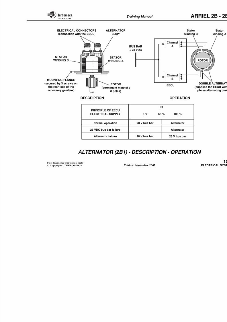
8/13/2019 Arriel_2B-2B1 11-02 En
http://slidepdf.com/reader/full/arriel2b-2b1-11-02-en 334/461
- Electrical system (71-51-00).......................................... 1
- Alternator (72-61-00)..................................................... 1
- Electrical harnesses (71-51-00)..................................... 1
Training Manual ARR
ELECTRICAL SYSTEM
Function
The system contributes to the various indicating and
control functions of the engine :
- Control
C t l t
Note : The accessories are dealt withchapters except the alternato
8/13/2019 Arriel_2B-2B1 11-02 En
http://slidepdf.com/reader/full/arriel2b-2b1-11-02-en 335/461
- Control system
- Safety system
- Maintenance aid.
Main characteristics
- Direct current : 28 VDC from aircraft electrical system
- Dedicated alternator electrical power : 100 VA, 48 V.
Main components
- Engine electrical components (accessories and sensors)
- Control and indicating components (aircraft)
- Engine Electronic Control Unit (installed in the airframe)
- Electrical harnesses.
Training Manual ARR
CONTROL
AND INDICATINGCOMPONENTS
Direct
28 VDC felectric
Dedicateelectric
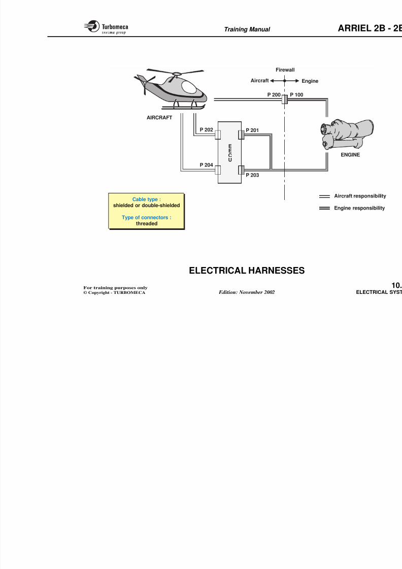
8/13/2019 Arriel_2B-2B1 11-02 En
http://slidepdf.com/reader/full/arriel2b-2b1-11-02-en 336/461
ACCESSORIESAND SENSORS
ELECTRICAL
HARNESSES
electric100 V
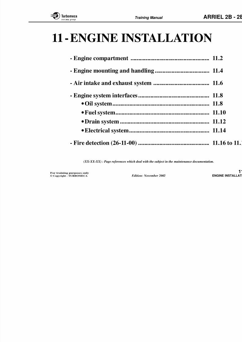
8/13/2019 Arriel_2B-2B1 11-02 En
http://slidepdf.com/reader/full/arriel2b-2b1-11-02-en 337/461
Training Manual ARR
ELCO
(connecti
Type :
Permanent magnet rotor- 2B: 3 phase alternator
- 2B1 : 3 phase double
alternator
Power :100 VA
8/13/2019 Arriel_2B-2B1 11-02 En
http://slidepdf.com/reader/full/arriel2b-2b1-11-02-en 338/461
Identificationplate
Drive shaft
(N1)Rotor
(permanent magnet)
MOUNTINGFLANGE
(mounting onaccesory gearbox)
A
Output voltage :< 48 V
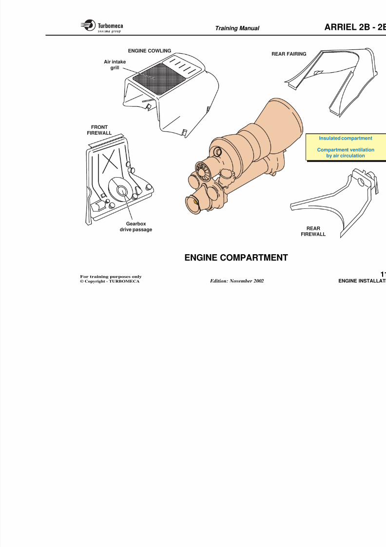
8/13/2019 Arriel_2B-2B1 11-02 En
http://slidepdf.com/reader/full/arriel2b-2b1-11-02-en 339/461
Training Manual ARR
ELECTRICAL CONNECTOR
(connection with the EECU)
ALTERNATOR
BODY
MOUNTING FLANGE(secured by 3 screws on
EECU(rectified three phase curre
(supppha
8/13/2019 Arriel_2B-2B1 11-02 En
http://slidepdf.com/reader/full/arriel2b-2b1-11-02-en 340/461
STATOR(3 phase winding)
ROTOR
(permanent magnet ;8 poles)
DESCRIPTION OPERATIO
Normal operation
28 VDC bus bar failure
0 %
N1
65 %
the rear face of theaccessory gearbox) +28 VDC
Internalsupply
PRINCIPLE OF EECU
ELECTRICAL SUPPLY
Alternator
Alternator
28 V bus bar
100 %
Training Manual
ARR
ALTERNATOR (2B1) - DESCRIPTION -
OPERATION
Description
The alternator is secured by 3 screws on the rear face of the accessory gearbox. The flange has threaded holes for extraction.
I i l d h f ll i
The three phase voltage is rectifiebridge housed in the EECU.
The output frequency is used by the ch for fuel flow control etc.
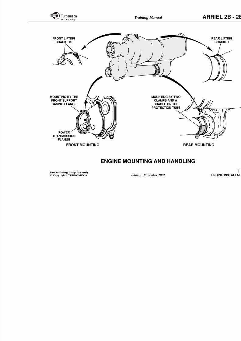
8/13/2019 Arriel_2B-2B1 11-02 En
http://slidepdf.com/reader/full/arriel2b-2b1-11-02-en 341/461
It includes the following components :
- A rotor driven by the accessory drive train (N1). It is provided with permanent magnets (8 poles)
- Two stators formed by two windings (A and B) withstator winding located at each side of the rotor. One for channel A and one for channel B
- Two electrical connectors for connection with the EECU,one connector for each channel.
The windings, all wiring and the connectors for each
channel are separate and insulated from one another.
Operation (for one winding, A or B)
The alternator transforms the mechanical power availableon the drive shaft into electrical power.
This electrical power is supplied to a channel of the
EECU electrical supply
The Engine Electronic Control Unit iseither from the aircraft 28 VDC bus b
alternator as follows :
- By the aircraft 28 VDC bus bar alonin the event of an alternator failur
- By the engine alternator above 65
The EECU switches automatically fro
to the alternator supply without any ef
Training Manual ARR
ChannelABUS BAR
+ 28 VDC
Stator
winding B
ELECTRICAL CONNECTORS(connection with the EECU)
STATORSTATOR
ALTERNATOR
BODY
8/13/2019 Arriel_2B-2B1 11-02 En
http://slidepdf.com/reader/full/arriel2b-2b1-11-02-en 342/461
ChannelB
STATORWINDING A
STATORWINDING B
ROTOR(permanent magnet ;
8 poles)
DESCRIPTION
MOUNTING FLANGE
(secured by 3 screws onthe rear face of the
accessory gearbox)
EECUD
(supph
RO
OPERATION
Normal operation
28 VDC bus bar failure
0 %
N1
65 %
PRINCIPLE OF EECU
ELECTRICAL SUPPLY
Alternator
Alternator
28 V bus bar
100 %
Training Manual
ARR
ELECTRICAL HARNESSES
Function
The harnesses connect the engine electrical components to
the EECU and the aircraft circuit.
Main characteristics
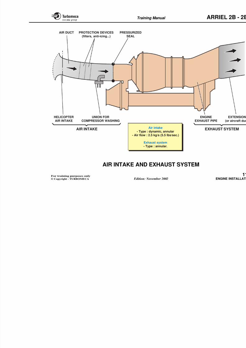
8/13/2019 Arriel_2B-2B1 11-02 En
http://slidepdf.com/reader/full/arriel2b-2b1-11-02-en 343/461
- Cable type : shielded or double-shielded
- Type of connectors : threaded.
Main components
Two engine harnesses :
- 1 engine to EECU harness (P201 and P203 connectors)
- 1 engine to Aircraft harness (P100 connector)
Training Manual ARR
P 100P 200
EngineAircraft
Firewall
8/13/2019 Arriel_2B-2B1 11-02 En
http://slidepdf.com/reader/full/arriel2b-2b1-11-02-en 344/461
P 203
P 204
P 201P 202
ENGIN
EECU
Aircraft r
Engine re
AIRCRAFT
Cable type :shielded or double-shielded
Type of connectors :threaded
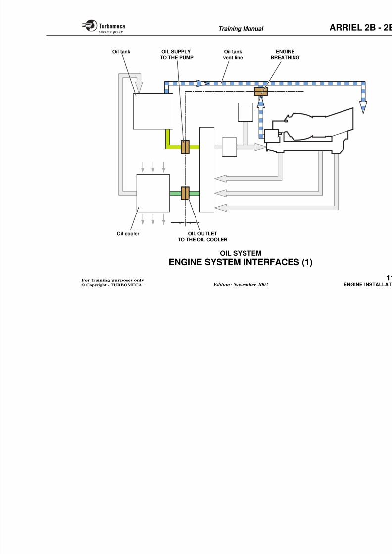
8/13/2019 Arriel_2B-2B1 11-02 En
http://slidepdf.com/reader/full/arriel2b-2b1-11-02-en 345/461
Training Manual ARR
11-ENGINE INSTALLATION
- Engine compartment .................................................... 1
8/13/2019 Arriel_2B-2B1 11-02 En
http://slidepdf.com/reader/full/arriel2b-2b1-11-02-en 346/461
- Engine mounting and handling .................................... 1
- Air intake and exhaust system ..................................... 1
- Engine system interfaces ............................................... 1
•Oil system................................................................ 1
•Fuel system.............................................................. 1
•Drain system ........................................................... 1
•Electrical system..................................................... 1
Training Manual ARR
ENGINE COMPARTMENT
Function
The engine compartment houses the engine.
Position
- At the rear of the helicopter main gearbox.
Description
The engine compartment inclu
components :
- The firewalls :• Front firewall
• Rear firewall
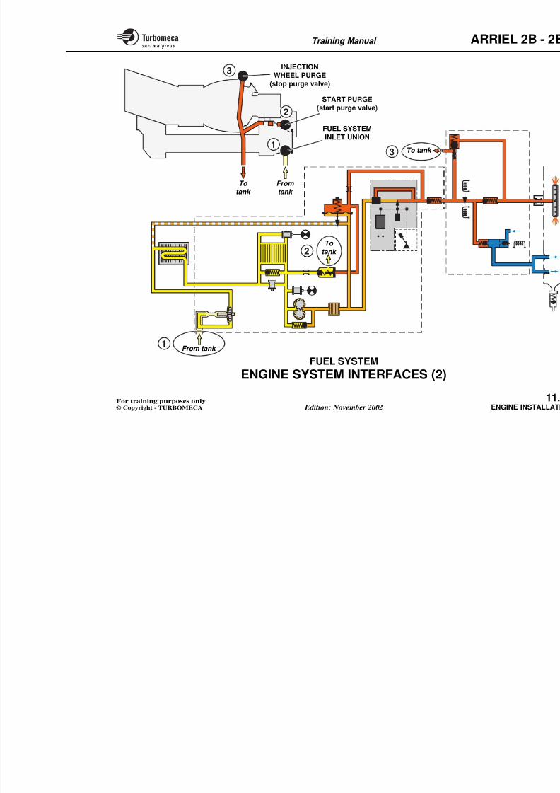
8/13/2019 Arriel_2B-2B1 11-02 En
http://slidepdf.com/reader/full/arriel2b-2b1-11-02-en 347/461
Main characteristics
- Insulated compartment
- Compartment ventilation by air circulation.
Main components
- Firewalls
- Cowlings
- Support platform.
Rear firewall
- Rear fairing
- Engine cowling which includes th
The compartment ventilation is ensuin order to maintain an acceptablevarious areas.
Training Manual ARR
Air intakegrill
ENGINE COWLINGREAR FAIRING
8/13/2019 Arriel_2B-2B1 11-02 En
http://slidepdf.com/reader/full/arriel2b-2b1-11-02-en 348/461
FRONTFIREWALL
Gearbox
Insulated
Compartmby air c
Training Manual ARR
ENGINE MOUNTING AND HANDLING
Function
The engine mountings attach the engine to the aircraft. The
lifting brackets permit engine lifting.
Position
E i i
Functional description
The front support is ensured by a ring
front flange of the front support cgearbox input casing.
The rear support is ensured by meanclamps on the protection tube.
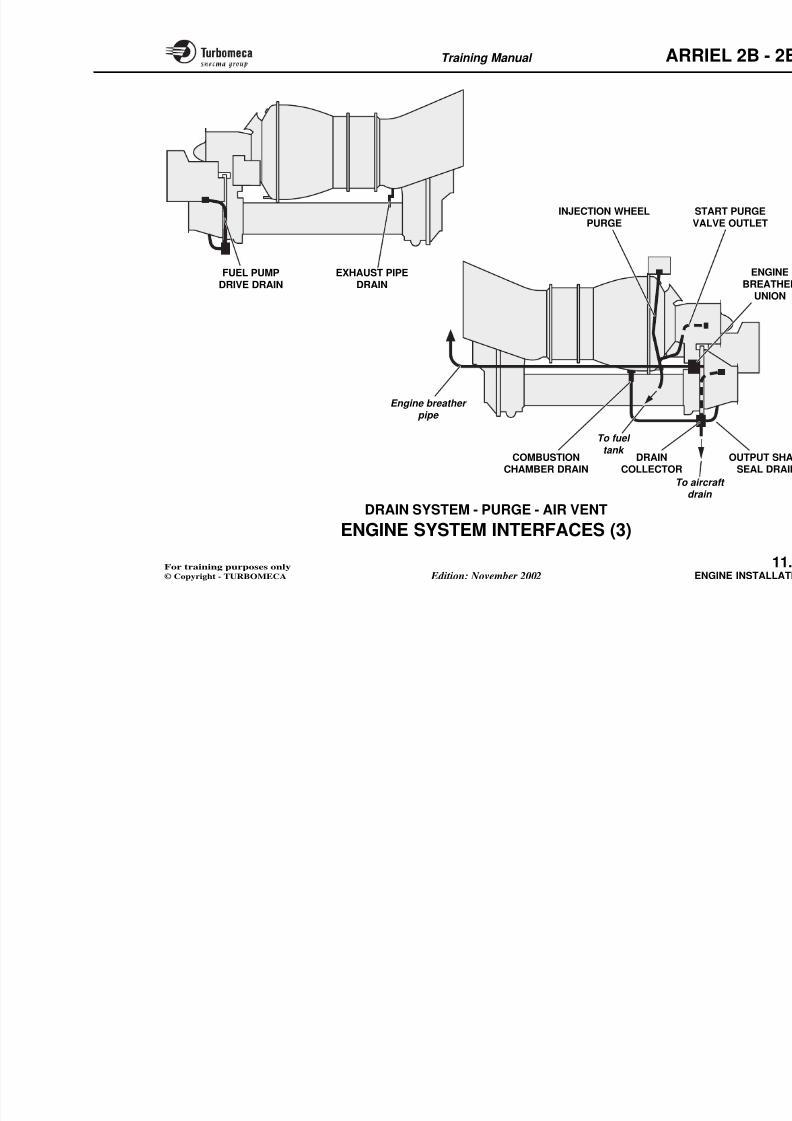
8/13/2019 Arriel_2B-2B1 11-02 En
http://slidepdf.com/reader/full/arriel2b-2b1-11-02-en 349/461
Engine mounting
- Front mounting : on the support casing front flange
- Rear mounting : a cradle and two clamps on the protectiontube.
Engine lifting
- Two lifting brackets at the junction of the compressorand combustion chamber casings
- One lifting bracket on the mounting flange of the exhaustpipe.
p p
The lifting brackets permit the instsling.
Note : The power transmission triangin the front support casing.
Training Manual ARR
FRONT LIFTINGBRACKETS
R

8/13/2019 Arriel_2B-2B1 11-02 En
http://slidepdf.com/reader/full/arriel2b-2b1-11-02-en 350/461
MOUNTING BY TWOCLAMPS AND ACRADLE ON THE
PROTECTION TUBE
MOUNTING BY THEFRONT SUPPORTCASING FLANGE
POWERTRANSMISSION
FLANGE
Training Manual ARR
AIR INTAKE AND EXHAUST SYSTEM
Air intake
Function
The air intake system directs the ambient air into theengine.
Position
Exhaust system
Function
The exhaust system discharges the ex
Position
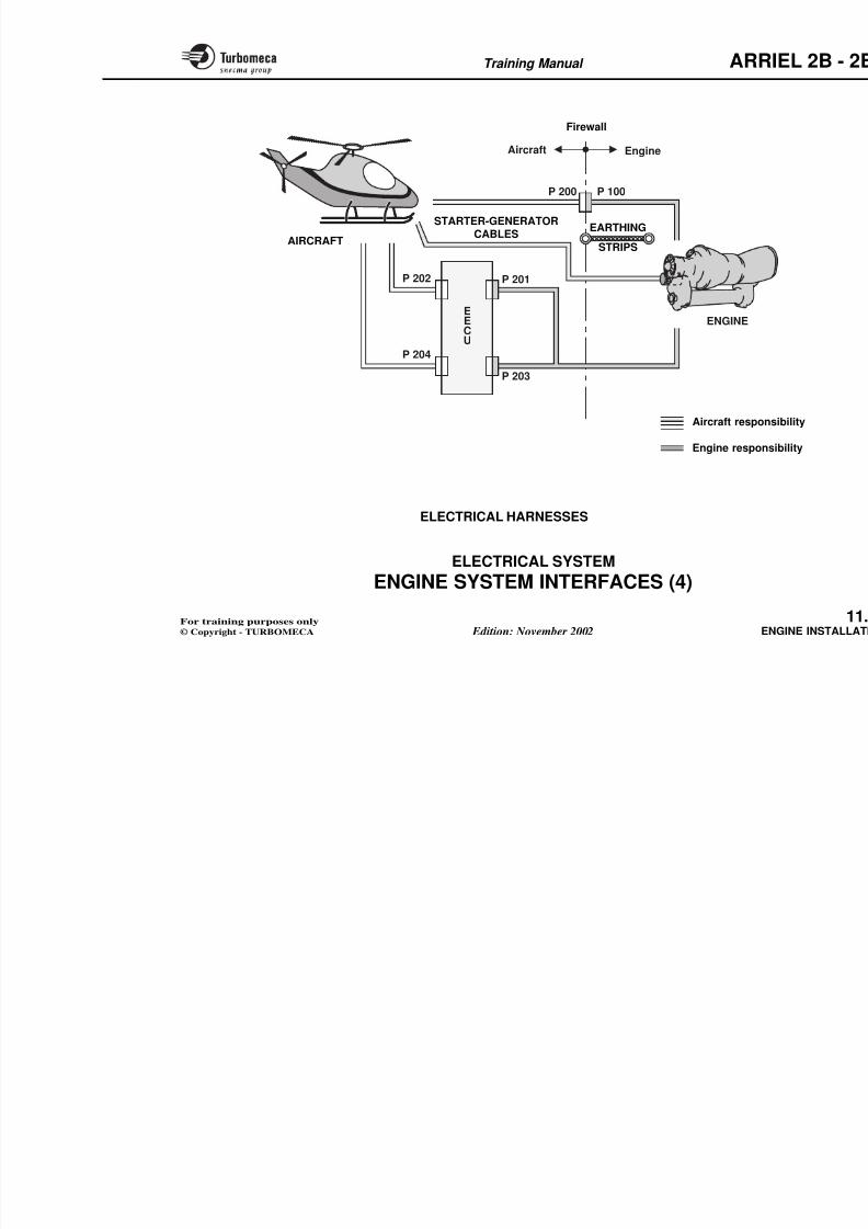
8/13/2019 Arriel_2B-2B1 11-02 En
http://slidepdf.com/reader/full/arriel2b-2b1-11-02-en 351/461
Position
- In front of the engine.
Main characteristics
- Type : dynamic, annular
- Air flow : 2.5 kg/s (5.5 lbs/sec.).
Main components
- Helicopter air intake
- Air duct.
Functional description
A circular flange on the compressor casing permitsconnection of the aircraft air duct.
The admission of air can be made through a static or adynamic intake which can be provided with protectiondevices (filters, anti-icing...).
A pressurized seal can also be fitted to improve the
- At the rear of the engine.
Main characteristics
- Type : annular.
Main components
- Engine exhaust pipe
- Exhaust extension (air frame).
Functional description
The exhaust expels the gases directlyto the aircraft by means of an extens
The extension is supplied by the aircis secured by a ring of bolts at the rear opipe.
Training Manual ARR
PROTECTION DEVICES
(filters, anti-icing...)
AIR DUCT PRESSURIZED
SEAL
8/13/2019 Arriel_2B-2B1 11-02 En
http://slidepdf.com/reader/full/arriel2b-2b1-11-02-en 352/461
ENGINE
EXHAUST PIPE
UNION FOR
COMPRESSOR WASHING
AIR INTAKE
HELICOPTER
AIR INTAKE
EXHAUAir intake
- Type : dynamic, annular- Air flow : 2.5 kg/s (5.5 lbs/sec.)
Exhaust system
Training Manual ARR
ENGINE SYSTEM INTERFACES (1)
Oil system
The oil system has three interfaces which are installed on
the front firewall, inside the engine compartment.
The oil system interfaces are :
- Oil outlet line to the oil cooler
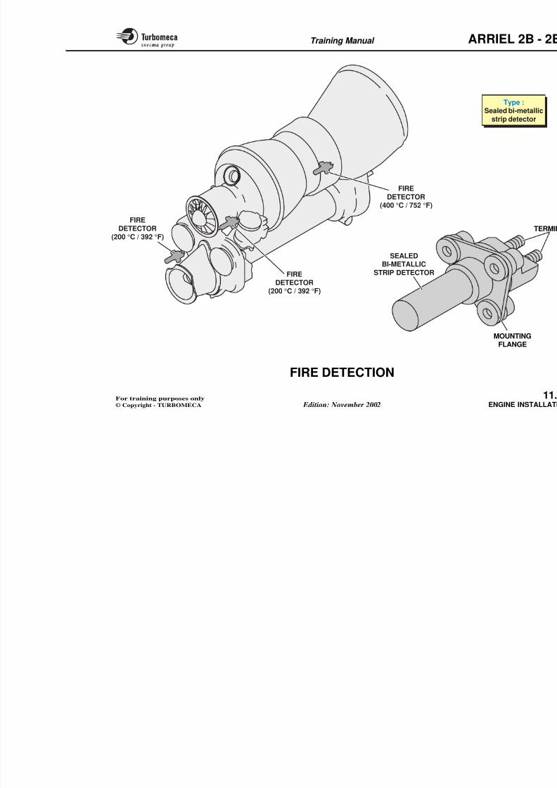
8/13/2019 Arriel_2B-2B1 11-02 En
http://slidepdf.com/reader/full/arriel2b-2b1-11-02-en 353/461
- Oil supply line to the oil pump pack. The oil supply lineis fitted with a drain plug on the interface
- Engine breathing and oil tank vent line.
Training Manual ARR
OIL SUPPLYTO THE PUMP
Oil tankvent line
ENGINEBREATHING
Oil tank
8/13/2019 Arriel_2B-2B1 11-02 En
http://slidepdf.com/reader/full/arriel2b-2b1-11-02-en 354/461
Training Manual ARR
ENGINE SYSTEM INTERFACES (2)
Fuel system
The engine is provided with :
- A fuel system inlet union
- A fuel return line (start purge and injection wheel purge)back to the tank.
8/13/2019 Arriel_2B-2B1 11-02 En
http://slidepdf.com/reader/full/arriel2b-2b1-11-02-en 355/461
Training Manual ARR
1
2
3INJECTION
WHEEL PURGE
(stop purge valve)
FUEL SYSTEM
INLET UNION
START PURGE
(start purge valve)
T t k
8/13/2019 Arriel_2B-2B1 11-02 En
http://slidepdf.com/reader/full/arriel2b-2b1-11-02-en 356/461
2
3
To tank
From tank
To tank
To
tank
Training Manual ARR
ENGINE SYSTEM INTERFACES (3)
Drain system - Purge - Air vent
Function
To drain fluids from certain engine components.
Position
Description
A drain collector is fitted on a bracke
accessory gearbox casing and is conpipe to an aircraft drain.
Three drain tubes are connected to th
The output shaft seal drain
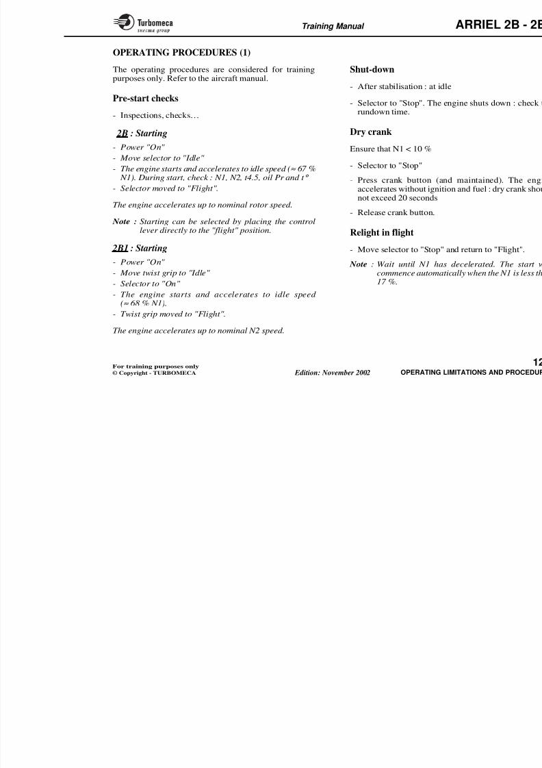
8/13/2019 Arriel_2B-2B1 11-02 En
http://slidepdf.com/reader/full/arriel2b-2b1-11-02-en 357/461
- Various pipelines on the engine connected to the aircraftdrain system.
Main characteristics
- Stainless steel tubes.
Main components
- Combustion chamber drain valve
- Engine breather union
- Fuel pump drive drain
- Injection wheel purge
- Start purge valve outlet
- The output shaft seal drain
- The fuel pump drive drain
- The combustion chamber drain.
The engine breather comprises a T unside of the accessory gearbox. Connthis union is the oil tank breather andwhich discharges into the exhaust.
The injection wheel purge drain and sconnect to the aircraft to be returned
The double exhaust pipe drain conwhich is connected to an aircraft ove
Training Manual ARR
INJECTION WHEEL S
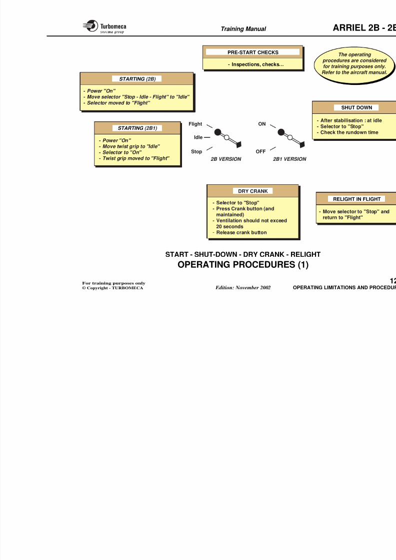
8/13/2019 Arriel_2B-2B1 11-02 En
http://slidepdf.com/reader/full/arriel2b-2b1-11-02-en 358/461
Engine breather pipe
COMBUSTION DRAIN
INJECTION WHEELPURGE
FUEL PUMPDRIVE DRAIN
EXHAUST PIPEDRAIN
SVA
To fuel
tank
Training Manual ARR
ENGINE SYSTEM INTERFACES (4)
Electrical system
The engine electrical harness is connected to the EECU
installed in the airframe and to the aircraft electricalsystem by means of three connectors (P100, P201, P203).
There are also earthing strips and starter-generator cables.
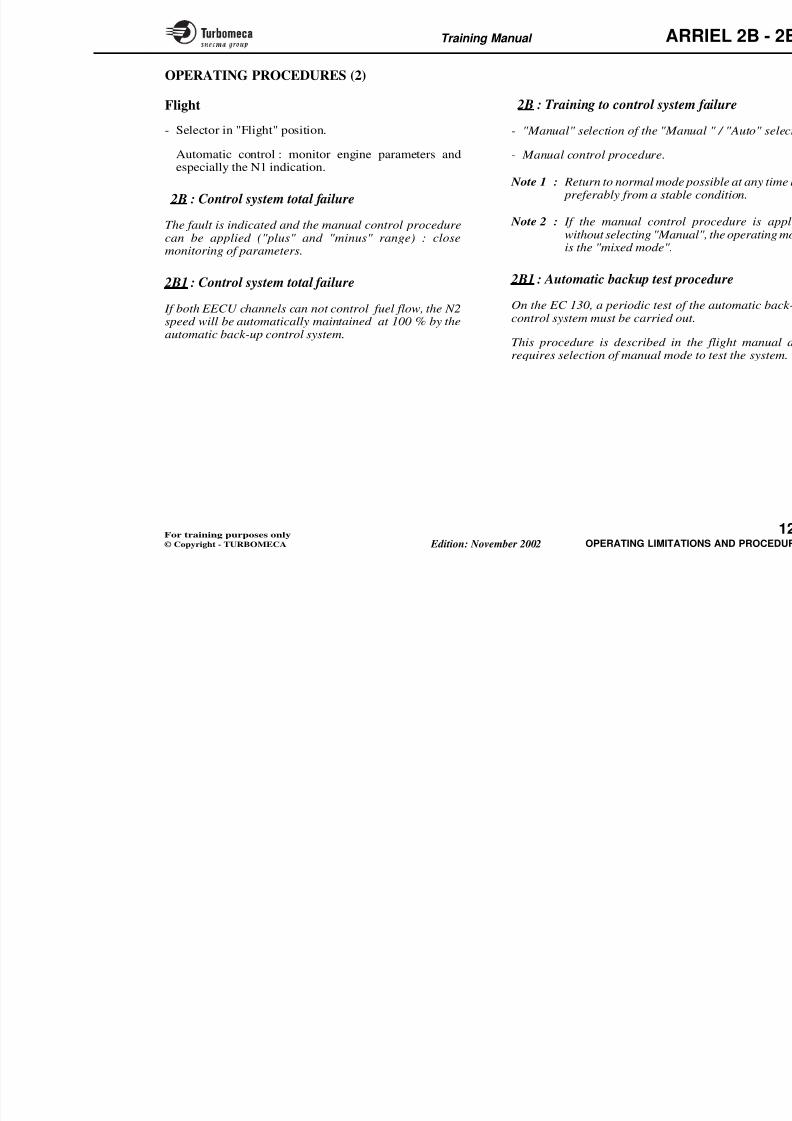
8/13/2019 Arriel_2B-2B1 11-02 En
http://slidepdf.com/reader/full/arriel2b-2b1-11-02-en 359/461
Training Manual ARR
P 100P 200
EARTHING
EngineAircraft
Firewall
STARTER-GENERATORCABLES
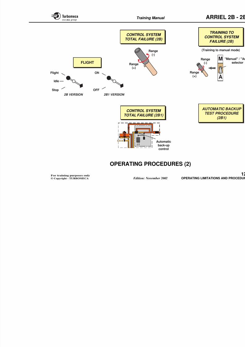
8/13/2019 Arriel_2B-2B1 11-02 En
http://slidepdf.com/reader/full/arriel2b-2b1-11-02-en 360/461
P 203
P 204
P 201P 202
STRIPS
ENGINEEECU
Aircraft respon
Engine respon
AIRCRAFTCABLES
Training Manual ARR
FIRE DETECTION
Function
The fire detection system detects overtemperature in the
engine compartment and gives a cockpit indication.
Position
- One detector on the right of the accessory gearbox
Functional description
Each fire detector comprises a bime
in a steel tube.
Each detector is fitted by three bolts
The two detectors on the accessory 200 °C (392 °F)
8/13/2019 Arriel_2B-2B1 11-02 En
http://slidepdf.com/reader/full/arriel2b-2b1-11-02-en 361/461
g y g
- One detector on top of the pump and metering unitassembly
- One detector on the rear flange of the combustionchamber casing left side.
Main characteristics
- Sealed bi-metallic strip detectors.
Main components
- Three detectors
- Electrical harness
- Detection logic system and indication in airframe.
200 C (392 F).
The one on the gas generator is set a
Training Manual ARR
Ses
8/13/2019 Arriel_2B-2B1 11-02 En
http://slidepdf.com/reader/full/arriel2b-2b1-11-02-en 362/461
FIREDETECTOR
(200 °C / 392 °F)
FIREDETECTOR
(200 °C / 392 °F)
FIREDETECTOR
(400 °C / 752 °F)
SEALEDBI-METALLICSTRIP DETECTOR
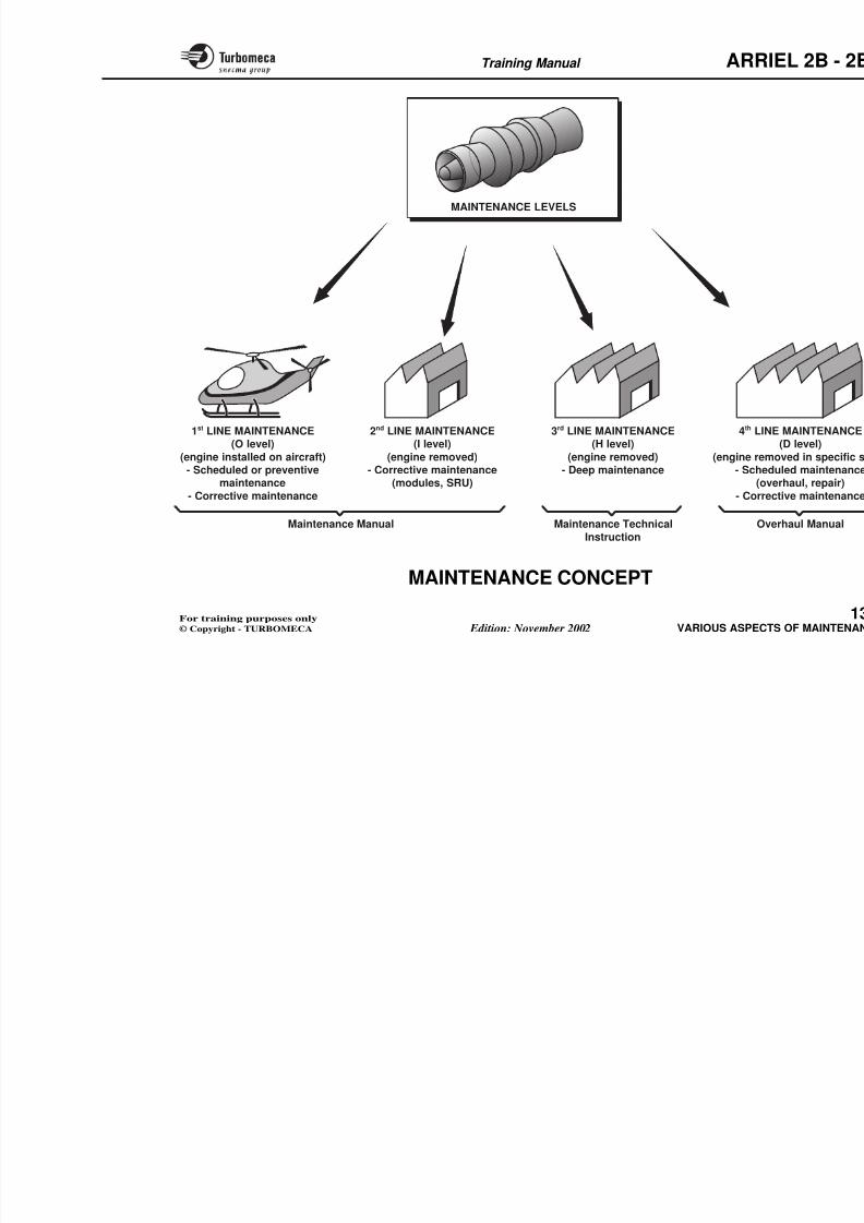
8/13/2019 Arriel_2B-2B1 11-02 En
http://slidepdf.com/reader/full/arriel2b-2b1-11-02-en 363/461
Training Manual ARR
12-OPERATING LIMITATIONAND PROCEDURES
8/13/2019 Arriel_2B-2B1 11-02 En
http://slidepdf.com/reader/full/arriel2b-2b1-11-02-en 364/461
AND PROCEDURES
- Operating limitations ................................................... 1
- Operating procedures .................................................. 1
Training Manual ARR
OPERATING LIMITATIONS
All operating limitations are defined in the officialdocuments :
- Flight manual
- Maintenance manual(s).
The main engine limitations are :
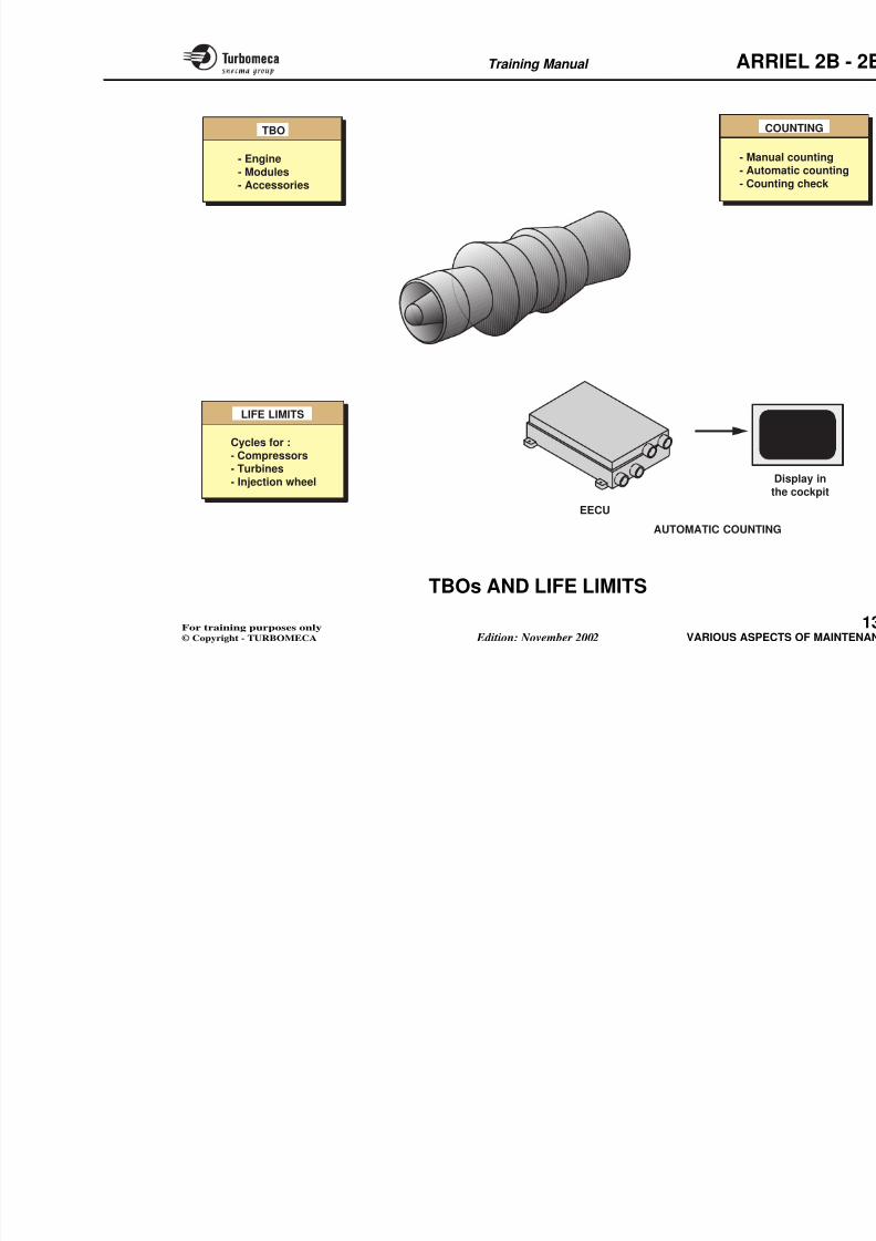
8/13/2019 Arriel_2B-2B1 11-02 En
http://slidepdf.com/reader/full/arriel2b-2b1-11-02-en 365/461
- Flight envelope
- Gas generator rotation speed N1
- Power turbine rotation speed N2
- t4.5 gas temperature
- Torque
- Miscellaneous (load factors, vibration...)
The systems general limitations are :
- Pressure, flow, volume, voltage...
Training Manual ARR
FLIGH T MANUAL
8/13/2019 Arriel_2B-2B1 11-02 En
http://slidepdf.com/reader/full/arriel2b-2b1-11-02-en 366/461
ENGINE AND SYSTEMLIMITATIONS
- Flight envelope- N1 rotation speed- N2 rotation speed- t4.5 gas temperature- Torque- Miscellaneous (load factors,
vibration...)- Pressure, flow, volume,
voltage...
Training Manual ARR
OPERATING PROCEDURES (1)
The operating procedures are considered for trainingpurposes only. Refer to the aircraft manual.
Pre-start checks
- Inspections, checks…
2B : Starting
- Power "On"
Shut-down
- After stabilisation : at idle
- Selector to "Stop". The engine shurundown time.
Dry crank
Ensure that N1 < 10 %
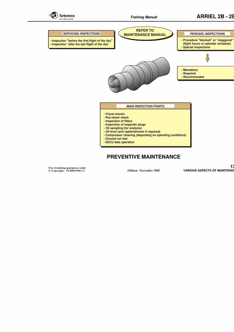
8/13/2019 Arriel_2B-2B1 11-02 En
http://slidepdf.com/reader/full/arriel2b-2b1-11-02-en 367/461
- Power On
- Move selector to "Idle"
- The engine starts and accelerates to idle speed (≈ 67 %
N1). During start, check : N1, N2, t4.5, oil Pr and t ° - Selector moved to "Flight".
The engine accelerates up to nominal rotor speed.
Note : Starting can be selected by placing the controllever directly to the "flight" position.
2B1 : Starting- Power "On"
- Move twist grip to "Idle"
- Selector to "On"
- The engine starts and accelerates to idle speed (≈ 68 % N1).
- Twist grip moved to "Flight".
Ensure that N1 < 10 %
- Selector to "Stop"
- Press crank button (and maintaaccelerates without ignition and funot exceed 20 seconds
- Release crank button.
Relight in flight
- Move selector to "Stop" and return Note : Wait until N1 has decelera
commence automatically whe17 %.
Training Manual ARR
SHU
PRE-START CHECKS
- Inspections, checks…
STARTING (2B)
- Power "On" - Move selector "Stop - Idle - Flight" to "Idle"
- Selector moved to "Flight"
The oprocedures for training
Refer to the
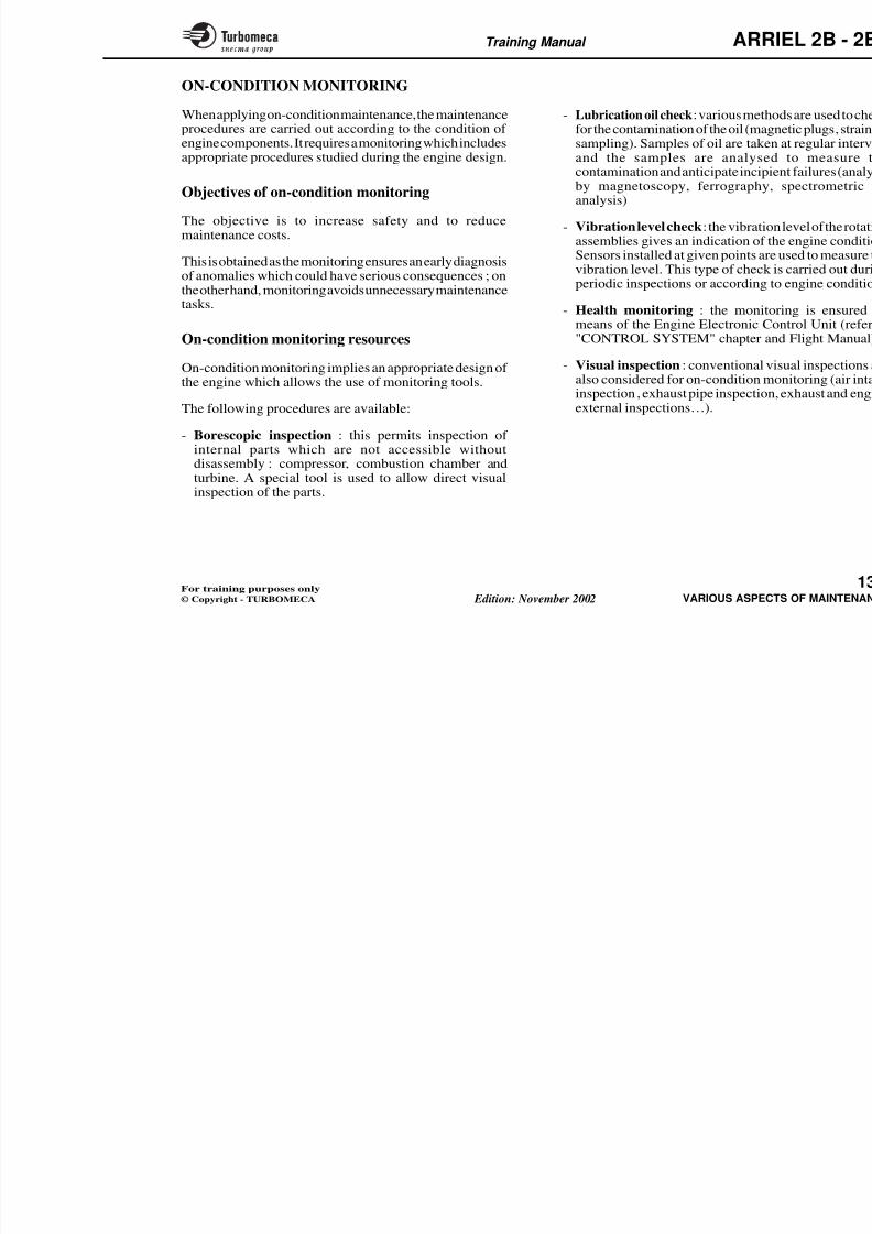
8/13/2019 Arriel_2B-2B1 11-02 En
http://slidepdf.com/reader/full/arriel2b-2b1-11-02-en 368/461
Flight
Idle
Stop
ON
OFF
DRY CRANK
SHU
RELIGH
STARTING (2B1)
- Power "On" - Move twist grip to "Idle"
- Selector to "On" - Twist grip moved to "Flight"
- After stabilis
- Selector to "
- Check the ru
- Selector to "Stop"- Press Crank button (and
maintained)- Ventilation should not exceed
20 seconds- Release crank button
2B VERSION 2B1 VERSION
- Move selectreturn to "F
Training Manual ARR
OPERATING PROCEDURES (2)
Flight
- Selector in "Flight" position.
Automatic control : monitor engine parameters andespecially the N1 indication.
2B : Control system total failure
2B : Training to control system f
- "Manual" selection of the "Manua
- Manual control procedure.
Note 1 : Return to normal mode pos preferably from a stable c
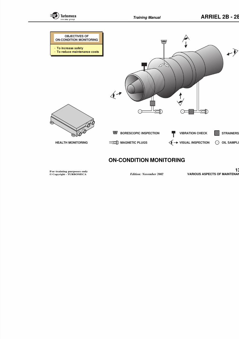
8/13/2019 Arriel_2B-2B1 11-02 En
http://slidepdf.com/reader/full/arriel2b-2b1-11-02-en 369/461
The fault is indicated and the manual control procedurecan be applied ("plus" and "minus" range) : closemonitoring of parameters.
2B1 : Control system total failure
If both EECU channels can not control fuel flow, the N2speed will be automatically maintained at 100 % by theautomatic back-up control system.
Note 2 : If the manual control prwithout selecting "Manualis the "mixed mode".
2B1 : Automatic backup test proc
On the EC 130, a periodic test of thecontrol system must be carried out.
This procedure is described in therequires selection of manual mode to
Training Manual ARR
FLIGHT
CONTROL SYSTEM TOTAL FAILURE (2B)
TRACONTR
FAIL
(Training t
Range(+)
Range(-)
Range(-)
8/13/2019 Arriel_2B-2B1 11-02 En
http://slidepdf.com/reader/full/arriel2b-2b1-11-02-en 370/461
Flight
Idle
Stop
ON
OFF
AUTOMA
TEST P
2B VERSION 2B1 VERSION
(+)
Automaticback-up
Range(+)
CONTROL SYSTEM
TOTAL FAILURE (2B1)
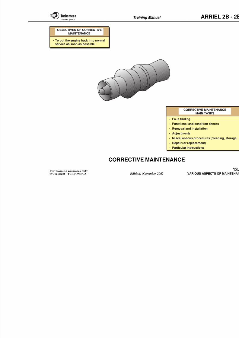
8/13/2019 Arriel_2B-2B1 11-02 En
http://slidepdf.com/reader/full/arriel2b-2b1-11-02-en 371/461
Training Manual ARR
13-VARIOUS ASPECTS OF
MAINTENANCE
8/13/2019 Arriel_2B-2B1 11-02 En
http://slidepdf.com/reader/full/arriel2b-2b1-11-02-en 372/461
- Maintenance concept .................................................... 1
- TBOs and life limits....................................................... 1
- Preventive maintenance ................................................ 1
- "On-condition" monitoring .......................................... 1
- Corrective maintenance ................................................ 1- Technical publications .................................................. 1
Training Manual ARR
MAINTENANCE CONCEPT
Introduction
The engine is designed to have a high availability rate with
reduced maintenance.
The main aspects of the maintenance concept are thefollowing :
- Effective modularity
Second line maintenance : engine m(I level).
- Corrective maintenance : SRU andinstallation.
Third line maintenance : deep
involves module repairs (H level).
- Corrective maintenance : compone
Fourth line maintenance : overhaul shop (D level).
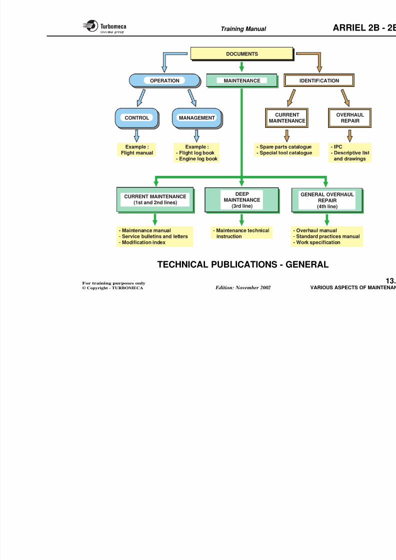
8/13/2019 Arriel_2B-2B1 11-02 En
http://slidepdf.com/reader/full/arriel2b-2b1-11-02-en 373/461
- Good accessibility
- Reduced removal and installation times
- On-condition facility
- Quick repair.
Maintenance levels
Four maintenance levels can be considered :
First line maintenance : engine installed on the aircraft(O level).
- Scheduled and preventive maintenance
• Checks and inspections
• Life limit or completed TBO removal.
- Corrective maintenance
• Fault detection
- Maintenance scheduled when the Twhen the life limit of a componen
- Corrective maintenance.
Other aspects of maintenance
Refer to the following pages.
Note 1 : LRU - Line Replaceable U
SRU - Shop Replaceable
Note 2 : The maintenance steps aroperator taking into accou
personnel and logistic con
As far as the engine manufathe current maintenance line) are defined and maintenance manual. De
Training Manual ARR
MAINTENANCE LEVELS
8/13/2019 Arriel_2B-2B1 11-02 En
http://slidepdf.com/reader/full/arriel2b-2b1-11-02-en 374/461
2nd LINE MAINTENANCE(I level)
(engine removed)- Corrective maintenance
(modules, SRU)
3rd LINE MAINTENANCE(H level)
(engine removed)- Deep maintenance
1st LINE MAINTENANCE(O level)
(engine installed on aircraft)- Scheduled or preventive
maintenance
- Corrective maintenance
4th LI
(engine re- Sche
(o
- Corr
Training Manual ARR
TBOs AND LIFE LIMITS
Engine, module and accessory TBOs
TBOs (operating Time Between Overhauls) are defined
for the engine, the modules and some accessories. TheseTBOs, determined by tests and experience, are subject toan extension programme.
The TBO is expressed in operating hours.
TBO components (flight hours)
The TBO is expressed in operating h
- Engine
- Modules
- Some accessories.
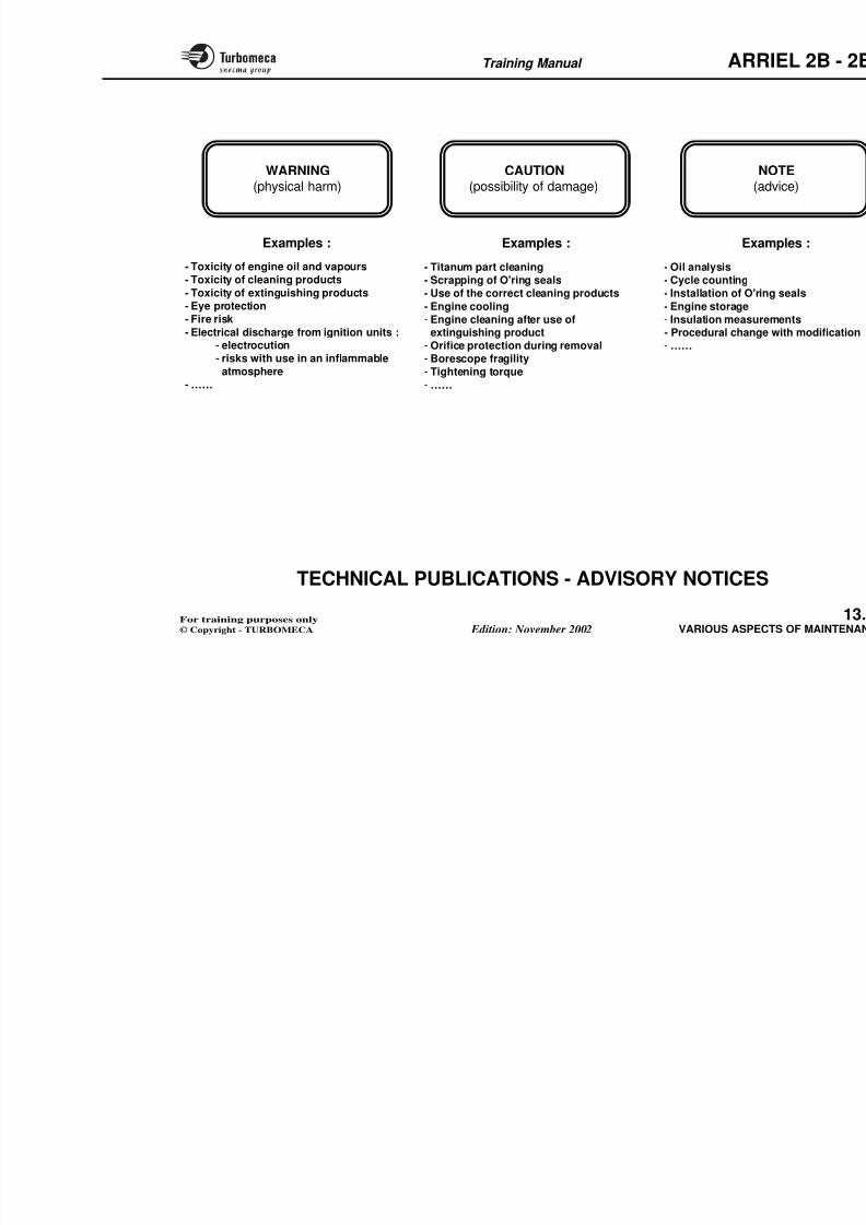
8/13/2019 Arriel_2B-2B1 11-02 En
http://slidepdf.com/reader/full/arriel2b-2b1-11-02-en 375/461
Component life limits
Certain components (mainly rotating parts such as
compressor, turbines, injection wheel…) have a life limitwhich requires the part to be scrapped when the limit isreached.
The life limit is expressed in operating cycles.
Counting of hours and cycles
A cycle is a clearly defined operating sequence. Cyclecounting is effected either manually or automatically. Themethod of counting cycles and the various limits aredescribed in Chapter 5 of the maintenance manual.
A counting check (comparison between automatic countingand manual counting) is a procedure planned in the periodicmaintenance.
A simple check can be carried out by comparing the two
Life limited components (N1 or N
Life limits are expressed in operatin
- Axial and centrifugal compressors
- Injection wheel (N1 cycles)
- Turbines (N1 or N2 cycles).
Consumable and repairable com
(examples)- Oil pumps (repairable)
- EECU (repairable)
- Igniter plug, start injector (consum
On-condition components (exam
Training Manual ARR
TBO
- Engine
- Modules- Accessories
- Manu
- Autom- Count
CO
8/13/2019 Arriel_2B-2B1 11-02 En
http://slidepdf.com/reader/full/arriel2b-2b1-11-02-en 376/461
EECU
t
LIFE LIMITS
Cycles for :- Compressors- Turbines
- Injection wheel
Training Manual ARR
PREVENTIVE MAINTENANCE
Preventive maintenance includes the procedures whichmust be systematically carried out and the procedureswhich are recommended.
Refer to maintenance manual (chapter 05-20-00).
Servicing inspections
- Inspection before the first flight of the day
I ti ft th l t fli ht f th d
- Required maintenance inspections
The engine manufacturer considerrequired maintenance inspections
although not affecting directly the be performed.
- Recommended maintenance inspe
The tasks of the recommended mainli t d i th t bl d i db th
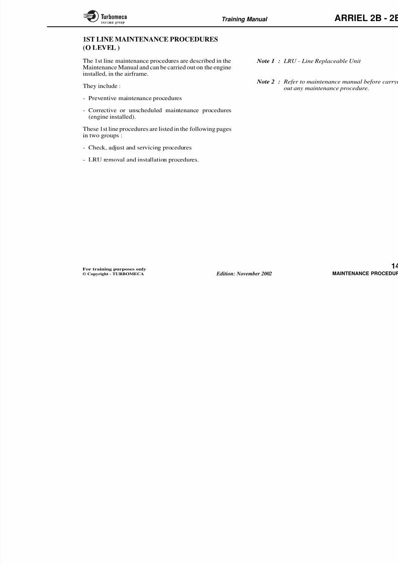
8/13/2019 Arriel_2B-2B1 11-02 En
http://slidepdf.com/reader/full/arriel2b-2b1-11-02-en 377/461
- Inspection after the last flight of the day.
Periodic inspections
- These procedures can be "blocked" (at fixed intervalsfor all the procedures) or staggered (each procedure isdistributed over a period of time to reduce the turnaroundtime while still respecting the intervals)
- Visits are scheduled as a function of flight hours (ex:every 500 hours) or calendar (ex: 2 years)
- Special inspections :• Particular inspections
• Inspections according to airworthiness.
The procedures are also qualified as follows:
- Mandatory maintenance inspections.
The actions to be carried out to meet the Airworthiness
listed in the table, are advised by thein order to improve the reliability,reduce the operating cost of the en
Main inspection points of preven
- Visual inspections
- Run-down check
- Magnetic plug and filter inspectio
- Oil sampling for analysis
- Oil level checks
- Compressor cleaning (according to o
- Operating checks and ground run
- EECU data operation :
• Hour counting check
• Cycle counting check
Training Manual ARR
REFER TOMAINTENANCE MANUAL PERIODIC IN
- Procedure "block (flight hours or ca
- Special inspectio
SERVICING INSPECTIONS
- Inspection "before the first flight of the day"- Inspection "after the last flight of the day"
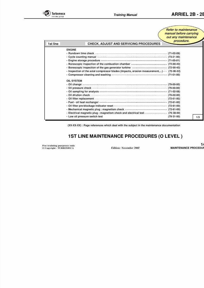
8/13/2019 Arriel_2B-2B1 11-02 En
http://slidepdf.com/reader/full/arriel2b-2b1-11-02-en 378/461
MAIN INSPECTION POINTS
- Visual checks- Run-down check- Inspection of filters- Inspection of magnetic plugs- Oil sampling (for analysis)- Oil level (and replenishment if required)- Compressor cleaning (depending on operating conditions)- Ground run test
- Mandatory- Required
- Recommended
Training Manual ARR
ON-CONDITION MONITORING
When applying on-condition maintenance, the maintenanceprocedures are carried out according to the condition of engine components. It requires a monitoring which includesappropriate procedures studied during the engine design.
Objectives of on-condition monitoring
The objective is to increase safety and to reducemaintenance costs.
- Lubrication oil check : various methfor the contamination of the oil (magsampling). Samples of oil are takeand the samples are analyse
contamination and anticipate incipiby magnetoscopy, ferrography,analysis)
- Vibration level check : the vibratioassemblies gives an indication of t
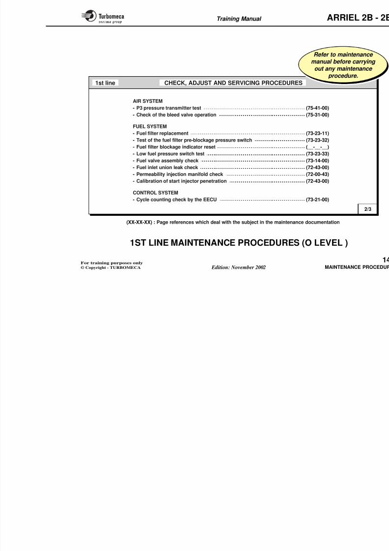
8/13/2019 Arriel_2B-2B1 11-02 En
http://slidepdf.com/reader/full/arriel2b-2b1-11-02-en 379/461
This is obtained as the monitoring ensures an early diagnosisof anomalies which could have serious consequences ; on
the other hand, monitoring avoids unnecessary maintenancetasks.
On-condition monitoring resources
On-condition monitoring implies an appropriate design of the engine which allows the use of monitoring tools.
The following procedures are available:
- Borescopic inspection : this permits inspection of internal parts which are not accessible withoutdisassembly : compressor, combustion chamber andturbine. A special tool is used to allow direct visualinspection of the parts.
gSensors installed at given points arevibration level. This type of check
periodic inspections or according t
- Health monitoring : the monitomeans of the Engine Electronic C"CONTROL SYSTEM" chapter a
- Visual inspection : conventional valso considered for on-condition minspection , exhaust pipe inspection
external inspections…).
Training Manual ARR
- To increase safety- To reduce maintenance costs
OBJECTIVES OFON-CONDITION MONITORING
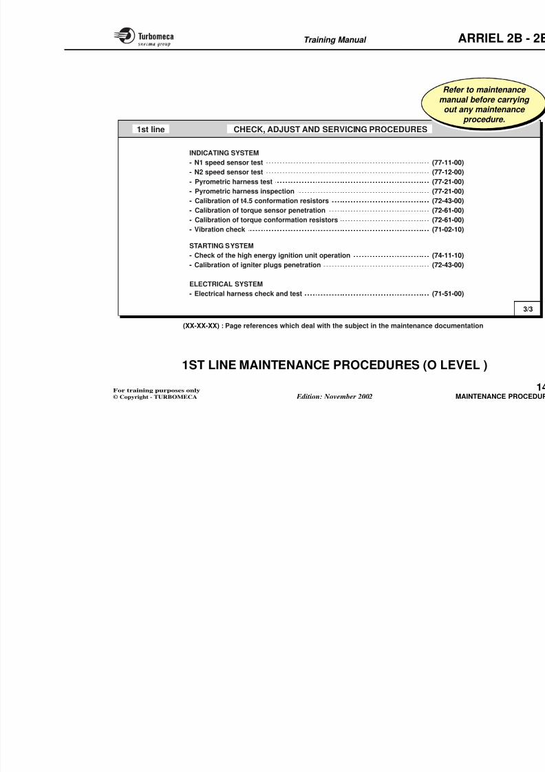
8/13/2019 Arriel_2B-2B1 11-02 En
http://slidepdf.com/reader/full/arriel2b-2b1-11-02-en 380/461
BORESCOPIC INSPECTION VIBRATION CHECK
Training Manual ARR
CORRECTIVE MAINTENANCE
Objective of corrective maintenance
The objective is to put the engine back into normal serviceas soon as possible. Corrective maintenance includes allprocedures which must be carried out when required(failure, fault…). It implies general and particular activities.
Corrective maintenance main tasks
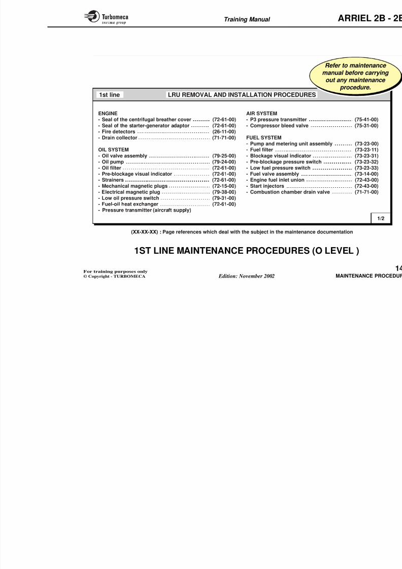
8/13/2019 Arriel_2B-2B1 11-02 En
http://slidepdf.com/reader/full/arriel2b-2b1-11-02-en 381/461
- Fault finding (refer to Maintenance Manual or TroubleShooting Manual : Chapter 71.00.06)
- Functional checks
- Condition checks
- Removal and installation : removal and installation of the complete power plant, of the accessories and of themodules and of some engine components as required.
Note : Assembly and disassembly of the engine is dealt with in general overhaul and repair.
- Adjustments
- Miscellaneous procedures : cleaning, storage…
- Repair or replacement
- Particular instructions : for example procedures in
Training Manual ARR
OBJECTIVES OF CORRECTIVEMAINTENANCE
- To put the engine back into normal
service as soon as possible
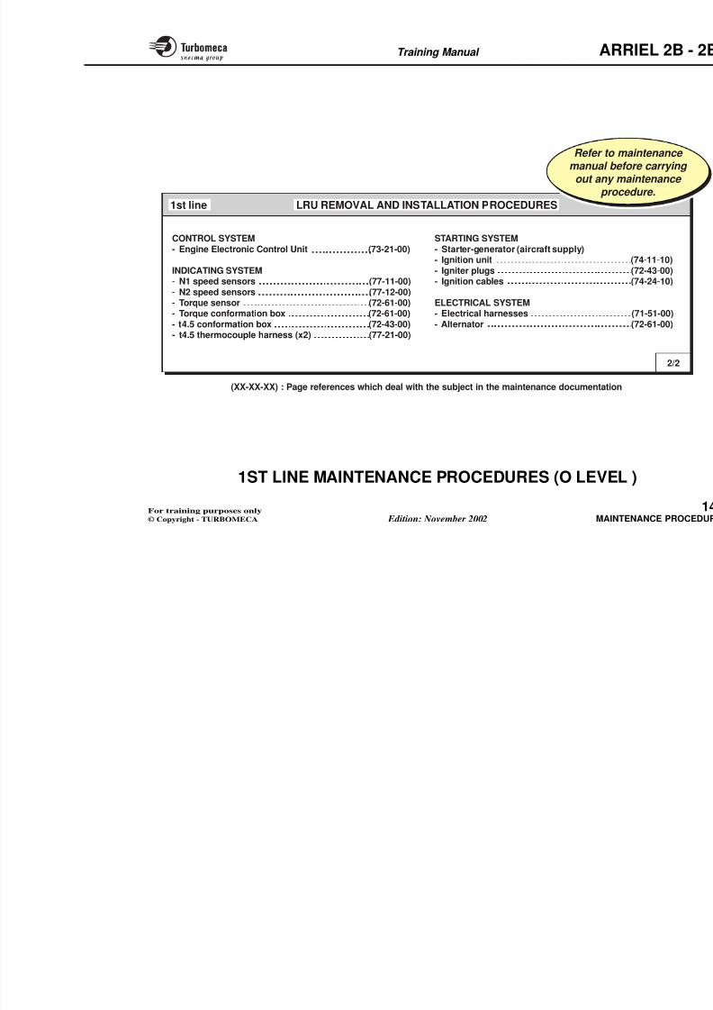
8/13/2019 Arriel_2B-2B1 11-02 En
http://slidepdf.com/reader/full/arriel2b-2b1-11-02-en 382/461
CORRECTIVE MAINMAIN TASK
- Fault finding
- Functional and condition ch
- Removal and installation
- Adjustments
- Miscellaneous procedures (
Training Manual ARR
TECHNICAL PUBLICATIONS - GENERAL
This part deals with the engine technical documentation.
Operation documents
The operation documents are :
- The control documents (e.g. : flight manual)
- The management documents :
• Flight log book
- The general overhaul and repair do
• Overhaul manual
• Standard practices manual
•
Work specification.
- The deep maintenance instruction• Maintenance technical instruct
Identification documents
8/13/2019 Arriel_2B-2B1 11-02 En
http://slidepdf.com/reader/full/arriel2b-2b1-11-02-en 383/461
• Flight log book
• Engine log book (records and provides informationon the engine status).
Maintenance documents
- The current maintenance documents are the following (1st
and 2nd lines) :• Maintenance manual (describes the engine and its
systems and all the maintenance procedures)
• Service bulletins (approved by the authorities, andissued to inform the operators of a modification or aninstruction which affects the operational aspects)
• Service letters (letter sent to inform the operator of certain instructions related to the operation of theengine)
• Modification index
Identification documents
The identification documents are :
- The current maintenance documen
• Spare parts catalogue (list andspare parts)
• Special tool catalogue (toolreferences).
- Overhaul and repair documents :
• Illustrated parts catalogue (illusengine and accessory parts ; ooverhaul)
• Descriptive list and drawings.
Note : Before all maintenance proc
- Refer to official documenta
Training Manual ARR
OPERATION
OC
DOCUMENTS
MAINTENANCE IDENTIFICATION
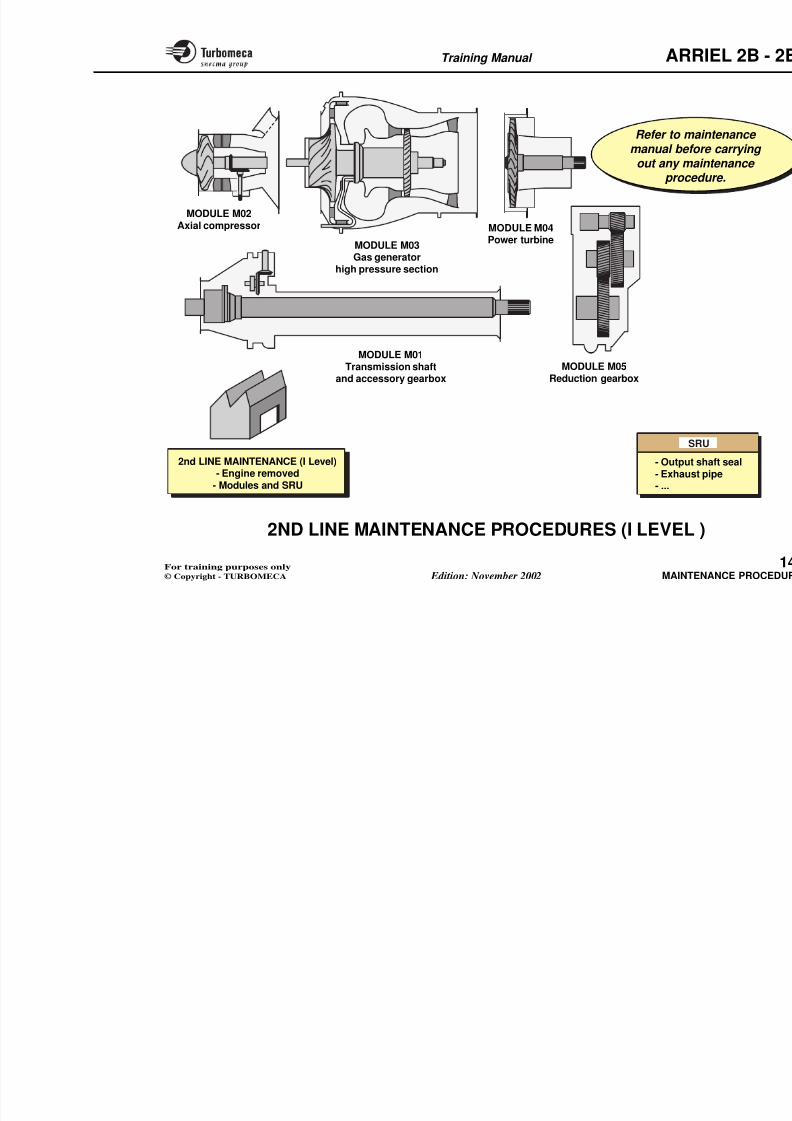
8/13/2019 Arriel_2B-2B1 11-02 En
http://slidepdf.com/reader/full/arriel2b-2b1-11-02-en 384/461
OVERREP
CURRENTMAINTENANCE
MANAGEMENTCONTROL
CURRENT MAINTENANCE(1st and 2nd lines)
DEEPMAINTENANCE
(3rd line)
GENERAL OVERHAUREPAIR(4th line)
Example :- Flight log book- Engine log book
Example :Flight manual
- Spare parts catalogue- Special tool catalogue
- IPC- Descrip
and dra
- Maintenance manual - Maintenance technical - Overhaul manual
Training Manual ARR
TECHNICAL PUBLICATIONS - ADVISORYNOTICES
Three types of advisory notice are used in the technicalpublications :
- WARNING
- CAUTION
- NOTE.
Examples
WARNING : do not breath the oil fu
in contact with the skin.
CAUTION : if the flush is being cametal particles in the oil system, chthoroughly clean the tank.
NOTE k h il l b f
8/13/2019 Arriel_2B-2B1 11-02 En
http://slidepdf.com/reader/full/arriel2b-2b1-11-02-en 385/461
Interpretation
WARNING : warns the reader of the possibility of physicalharm (e.g. : wounding, intoxication, electrocution).
CAUTION : warns the reader of the possibility of damagingthe engine or tooling.
NOTE : gives the reader advice on how best to carry out atask.
NOTE : take the oil sample beforreplenishment.
Training Manual ARR
Examples :
WARNING(physical harm)
Examples :
CAUTION(possibility of damage)
Exa
N(ad
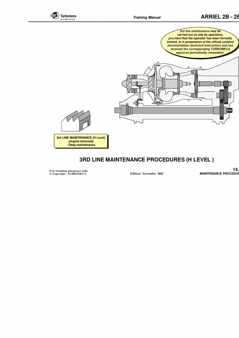
8/13/2019 Arriel_2B-2B1 11-02 En
http://slidepdf.com/reader/full/arriel2b-2b1-11-02-en 386/461
p
- Toxicity of engine oil and vapours
- Toxicity of cleaning products
- Toxicity of extinguishing products- Eye protection
- Fire risk
- Electrical discharge from ignition units :- electrocution
- risks with use in an inflammable
atmosphere
-……
p
- Titanum part cleaning
- Scrapping of O'ring seals
- Use of the correct cleaning products- Engine cooling
- Engine cleaning after use ofextinguishing product
- Orifice protection during removal
- Borescope fragility
- Tightening torque
-……
- Oil analysis
- Cycle counting
- Installation of O'rin- Engine storage
- Insulation measure- Procedural change
-……
8/13/2019 Arriel_2B-2B1 11-02 En
http://slidepdf.com/reader/full/arriel2b-2b1-11-02-en 387/461
Training Manual ARR
14-MAINTENANCE PROCED
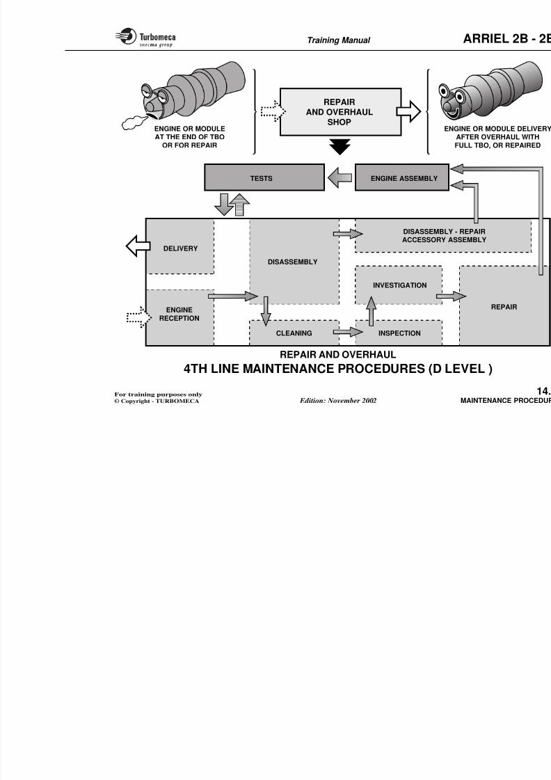
8/13/2019 Arriel_2B-2B1 11-02 En
http://slidepdf.com/reader/full/arriel2b-2b1-11-02-en 388/461
- 1st line (O level ) ............................................................ 1
- 2nd line (I level ) ............................................................ 1
- 3rd line (H level ) ........................................................... 1
- 4th line (D level ) ............................................................ 1
Training Manual ARR
1ST LINE MAINTENANCE PROCEDURES
(O LEVEL )
The 1st line maintenance procedures are described in theMaintenance Manual and can be carried out on the engineinstalled, in the airframe.
They include :
- Preventive maintenance procedures
- Corrective or unscheduled maintenance procedures( i i t ll d)
Note 1 : LRU - Line Replaceable U
Note 2 : Refer to maintenance manout any maintenance proc

8/13/2019 Arriel_2B-2B1 11-02 En
http://slidepdf.com/reader/full/arriel2b-2b1-11-02-en 389/461
(engine installed).
These 1st line procedures are listed in the following pagesin two groups :
- Check, adjust and servicing procedures
- LRU removal and installation procedures.
Training Manual ARR
ENGINE
- Rundown time check (71-02-09)
- Cycle counting manual (73-21-00)
CHECK, ADJUST AND SERVICING PROCEDURES1st line
Refer to mmanual befout any m
proc
8/13/2019 Arriel_2B-2B1 11-02 En
http://slidepdf.com/reader/full/arriel2b-2b1-11-02-en 390/461
- Engine storage procedure (71-05-01)
- Borescopic inspection of the combustion chamber (72-00-43)
- Borescopic inspection of the gas generator turbine (72-00-43)- Inspection of the axial compressor blades (impacts, erosion measurement,...) (72-00-32)
- Compressor cleaning and washing (71-01-00)
OIL SYSTEM
- Oil change (79-00-00)
- Oil pressure check (79-00-00)
- Oil sampling for analysis (71-02-08)
- Oil dilution check (70-02-00)- Oil filter replacement (72-61-00)
- Fuel - oil heat exchanger (72-61-00)
- Oil filter pre-blockage indicator reset (72-61-00)
- Mechanical magnetic plug : magnetism check (72-61-00)
- Electrical magnetic plug : magnetism check and electrical test (79-38-00)
- Low oil pressure switch test (79-31-00)
Training Manual ARR
AIR SYSTEM
- P3 pressure transmitter test (75-41-00)
Ch k f h bl d l i (75 31 00)
CHECK, ADJUST AND SERVICING PROCEDURES1st line
Refer to mamanual befoout any ma
proce
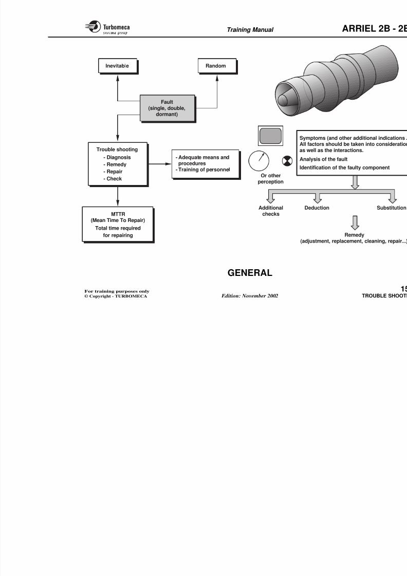
8/13/2019 Arriel_2B-2B1 11-02 En
http://slidepdf.com/reader/full/arriel2b-2b1-11-02-en 391/461
- Check of the bleed valve operation (75-31-00)
FUEL SYSTEM
- Fuel filter replacement (73-23-11)
- Test of the fuel filter pre-blockage pressure switch (73-23-32)
- Fuel filter blockage indicator reset (__-__-__)
- Low fuel pressure switch test (73-23-33)
- Fuel valve assembly check (73-14-00)
- Fuel inlet union leak check (72-43-00)
- Permeability injection manifold check (72-00-43)
- Calibration of start injector penetration (72-43-00)
CONTROL SYSTEM
- Cycle counting check by the EECU (73-21-00)
(XX-XX-XX) : Page references which deal with the subject in the maintenance documentation
Training Manual ARR
INDICATING SYSTEM
CHECK, ADJUST AND SERVICING PROCEDURES1st line
Refer to mmanual bef
out any mproce
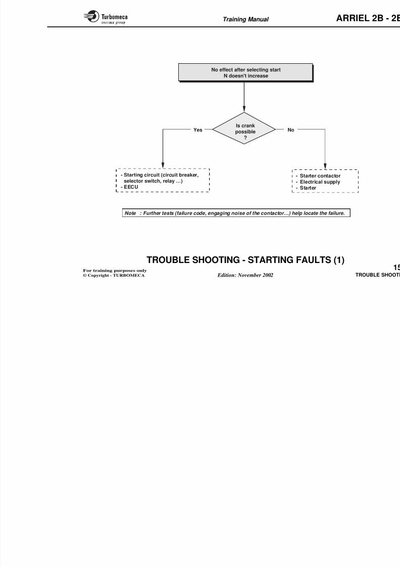
8/13/2019 Arriel_2B-2B1 11-02 En
http://slidepdf.com/reader/full/arriel2b-2b1-11-02-en 392/461
- N1 speed sensor test (77-11-00)
- N2 speed sensor test (77-12-00)
- Pyrometric harness test (77-21-00)- Pyrometric harness inspection (77-21-00)
- Calibration of t4.5 conformation resistors (72-43-00)
- Calibration of torque sensor penetration (72-61-00)
- Calibration of torque conformation resistors (72-61-00)
- Vibration check (71-02-10)
STARTING SYSTEM
- Check of the high energy ignition unit operation (74-11-10)- Calibration of igniter plugs penetration (72-43-00)
ELECTRICAL SYSTEM
- Electrical harness check and test (71-51-00)
(XX XX XX) P f hi h d l i h h bj i h i d i
Training Manual ARR
LRU REMOVAL AND INSTALLATION PROCEDURES
ENGINE AIR SYSTEM
1st line
Refer to mamanual befo
out any maproce
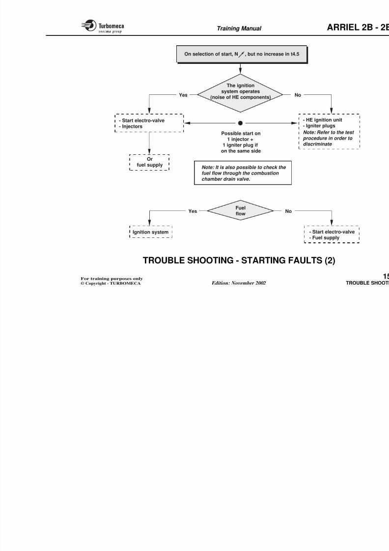
8/13/2019 Arriel_2B-2B1 11-02 En
http://slidepdf.com/reader/full/arriel2b-2b1-11-02-en 393/461
- Seal of the centrifugal breather cover (72-61-00)
- Seal of the starter-generator adaptor (72-61-00)- Fire detectors (26-11-00)
- Drain collector (71-71-00)
OIL SYSTEM
- Oil valve assembly (79-25-00)- Oil pump (79-24-00)
- Oil filter (72-61-00)- Pre-blockage visual indicator (72-61-00)- Strainers (72-61-00)
- Mechanical magnetic plugs (72-15-00)- Electrical magnetic plug (79-38-00)
- Low oil pressure switch (79-31-00)- Fuel-oil heat exchanger (72-61-00)- Pressure transmitter (aircraft supply)
- P3 pressure transmitter (
- Compressor bleed valve (
FUEL SYSTEM- Pump and metering unit assembly (- Fuel filter (
- Blockage visual indicator (- Pre-blockage pressure switch (
- Low fuel pressure switch (- Fuel valve assembly (- Engine fuel inlet union (
- Start injectors (- Combustion chamber drain valve (
(XX-XX-XX) : Page references which deal with the subject in the maintenance documentation
Training Manual ARR
LRU REMOVAL AND INSTALLATION PROCEDURES1st line
Refer to mamanual befoout any ma
proce
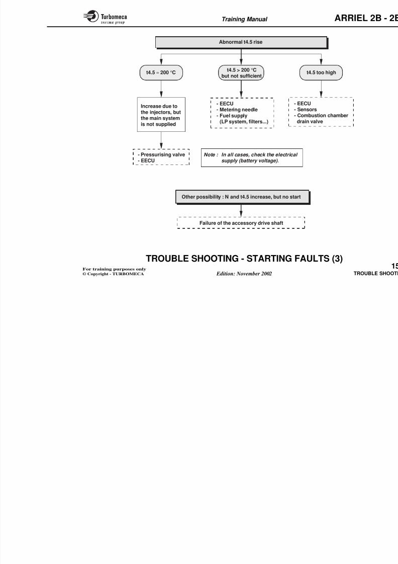
8/13/2019 Arriel_2B-2B1 11-02 En
http://slidepdf.com/reader/full/arriel2b-2b1-11-02-en 394/461
CONTROL SYSTEM- Engine Electronic Control Unit (73-21-00)
INDICATING SYSTEM- N1 speed sensors (77-11-00)- N2 speed sensors (77-12-00)- Torque sensor (72-61-00)- Torque conformation box (72-61-00)- t4.5 conformation box (72-43-00)
- t4.5 thermocouple harness (x2) (77-21-00)
STARTING SYSTEM- Starter-generator (aircraft supply)- Ignition unit- Igniter plugs- Ignition cables
ELECTRICAL SYSTEM- Electrical harnesses- Alternator
(XX-XX-XX) : Page references which deal with the subject in the maintenance documentation
U O S O OC U Sst e
Training Manual ARR
2ND LINE MAINTENANCE PROCEDURES
(I LEVEL )
The 2nd line maintenance procedures are described in theMaintenance Manual and must be carried out on theengine removed from the airframe.
They consist of scheduled and unscheduled maintenanceprocedures, engine removed :
- Module removal and installation
SRU removal and installation (e g output shaft seal
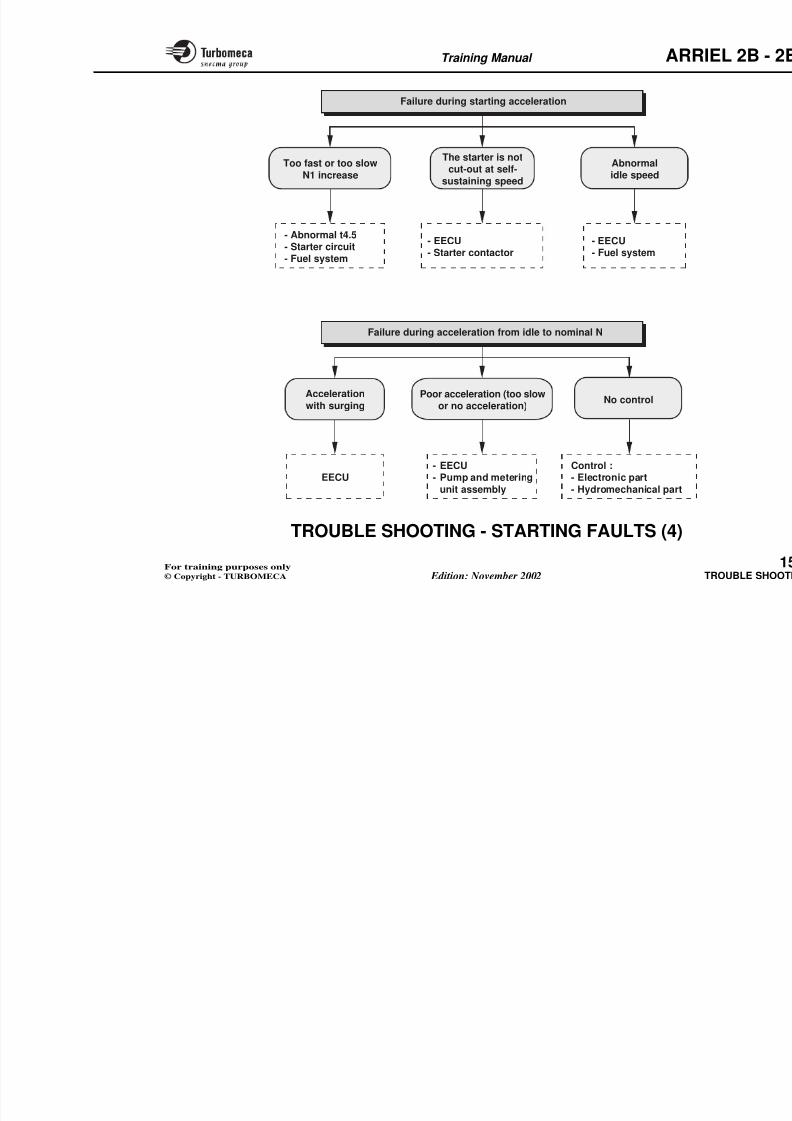
8/13/2019 Arriel_2B-2B1 11-02 En
http://slidepdf.com/reader/full/arriel2b-2b1-11-02-en 395/461
- SRU removal and installation (e.g. output shaft seal,exhaust system...)
Note : SRU: Shop Replaceable Unit.
Training Manual ARR
MODULE M02Axial compressor MODULE M04
Refer to mamanual befo
out any maproced
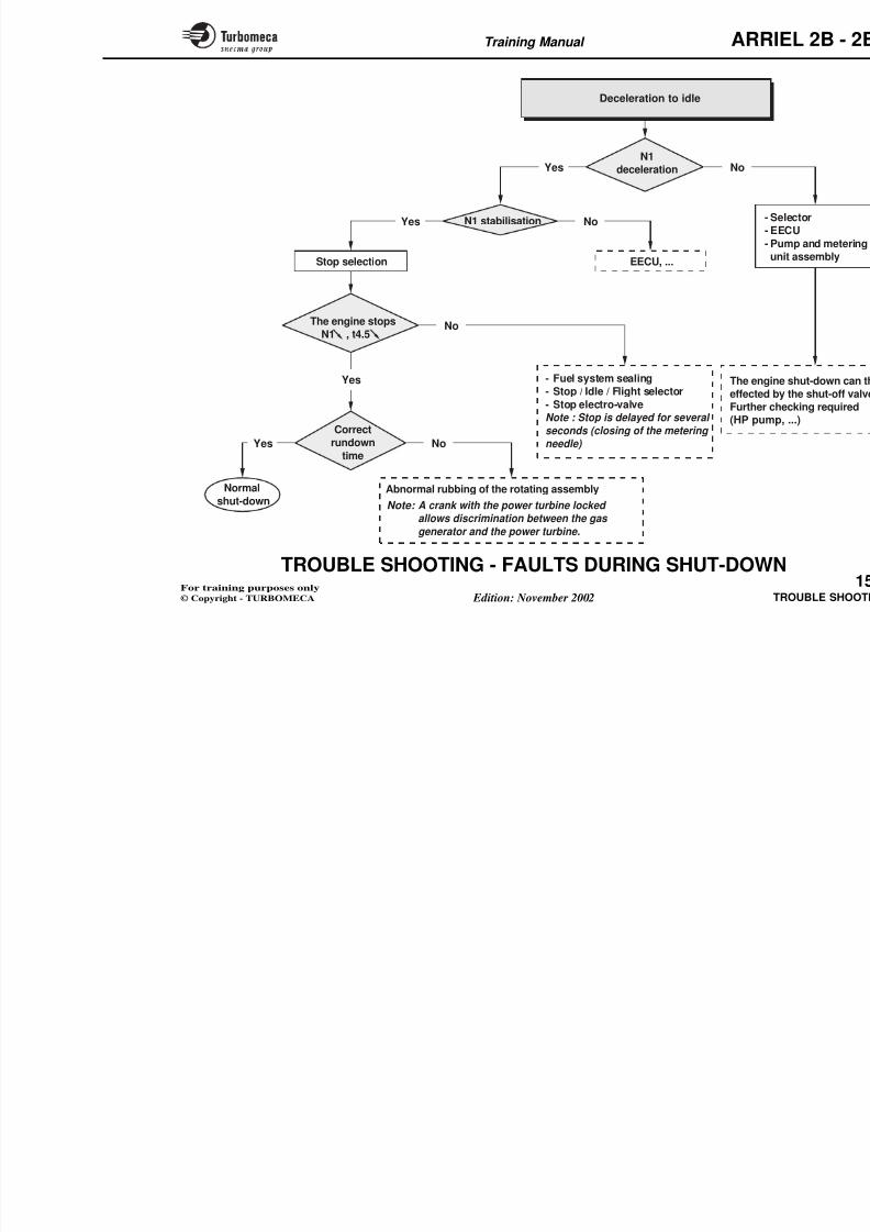
8/13/2019 Arriel_2B-2B1 11-02 En
http://slidepdf.com/reader/full/arriel2b-2b1-11-02-en 396/461
2nd LINE MAINTENANCE (I Level) - Output s
MODULE M03Gas generator
high pressure section
Power turbine
MODULE M05Reduction gearbox
MODULE M01Transmission shaft
and accessory gearbox
SR
Training Manual ARR
3RD LINE MAINTENANCE PROCEDURES
(H LEVEL )
Definition
The 3rd line (or deep) maintenance procedures are carriedout on removed major parts (e.g. modules) in a workshop.
They consist of replacement or reconditioning of subassemblies without repair or adjustment (e.g. injectionwheel replacement).
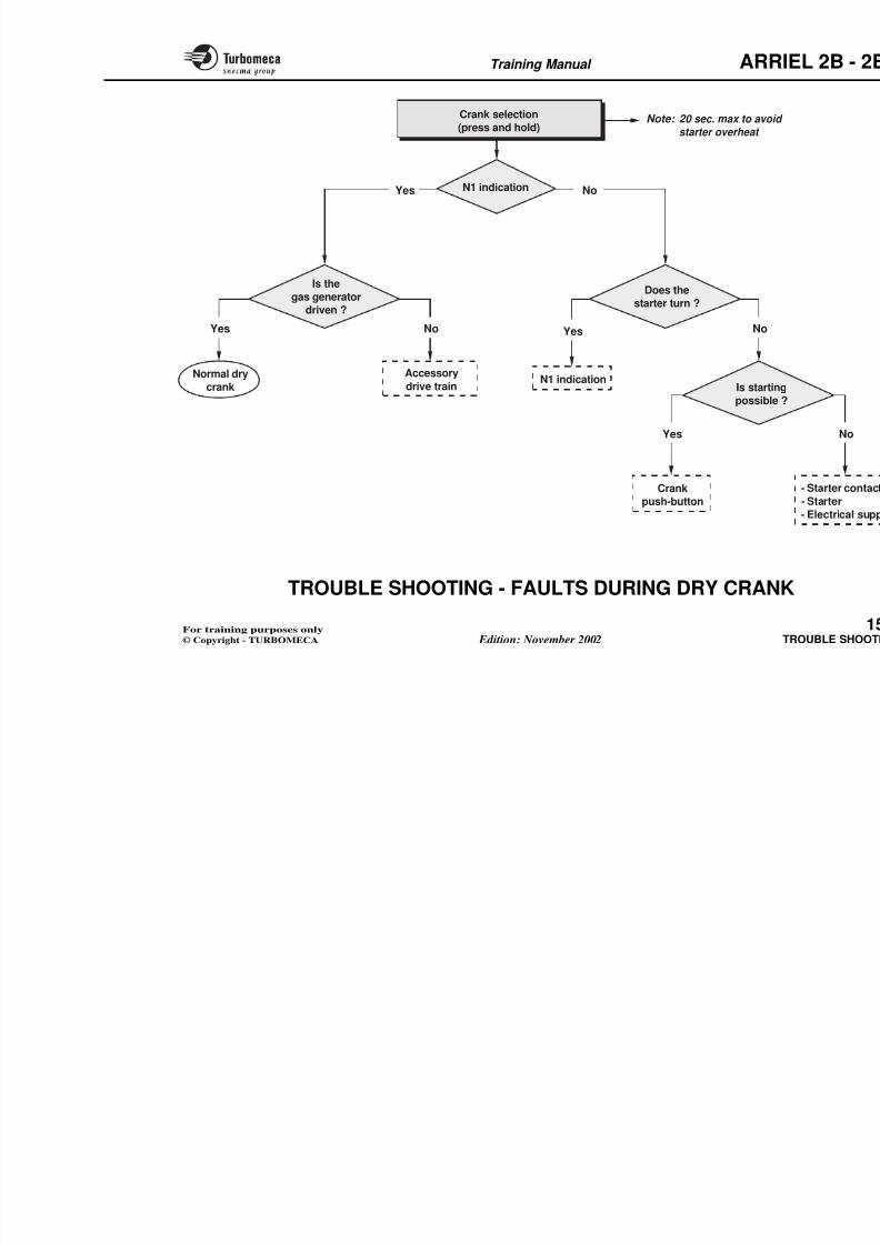
8/13/2019 Arriel_2B-2B1 11-02 En
http://slidepdf.com/reader/full/arriel2b-2b1-11-02-en 397/461
Procedure
3rd Line Maintenance may be carried out on site byoperators, provided that the operator has been formallytrained, is in possession of the official updateddocumentation (technical instruction) and has receivedthe corresponding TURBOMECA approval (periodicallyrenewable).
Training Manual ARR
3rd line maintenance m
carried out on site by opprovided that the operator has
trained, is in possession of the documentation (technical instru
received the corresponding Tapproval (periodically ren
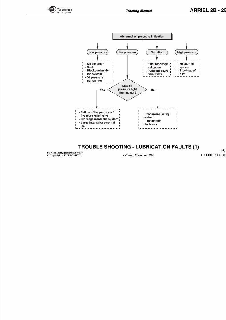
8/13/2019 Arriel_2B-2B1 11-02 En
http://slidepdf.com/reader/full/arriel2b-2b1-11-02-en 398/461
3rd LINE MAINTENANCE (H Level)(engine removed)
Training Manual ARR
4TH LINE MAINTENANCE PROCEDURES
(D LEVEL )
Repair and overhaul
Overhaul
Overhaul is a maintenance operation which is carried outwhen the engine (or module) has reached the end of itsTBO, either in operating hours or cycles.
The overhauled engine (or module) is then put back into
Main procedure steps
- Engine reception
- Disassembly
- Cleaning
- Inspection
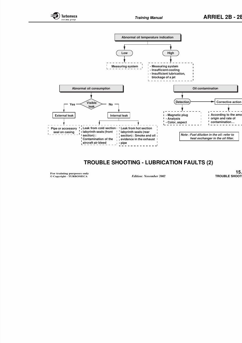
8/13/2019 Arriel_2B-2B1 11-02 En
http://slidepdf.com/reader/full/arriel2b-2b1-11-02-en 399/461
The overhauled engine (or module) is then put back intoservice with zero hours for a new TBO.
Repair
Repair is a maintenance operation which must be carriedout when the engine (or module) is unserviceable.
After a repair, the engine (or module) is returned to servicewith a TBO according to the work carried out and the
engine standard.
Note : TBO : Time Between Overhaul.
- Investigation
- Repair
- Installation (of engine and accesso
- Tests
- Delivery.
Training Manual ARR
ENGINE OR MODULEAT THE END OF TBO
OR FOR REPAIR
ENGINE OR MAFTER OV
FULL TBO
REPAIR
AND OVERHAULSHOP
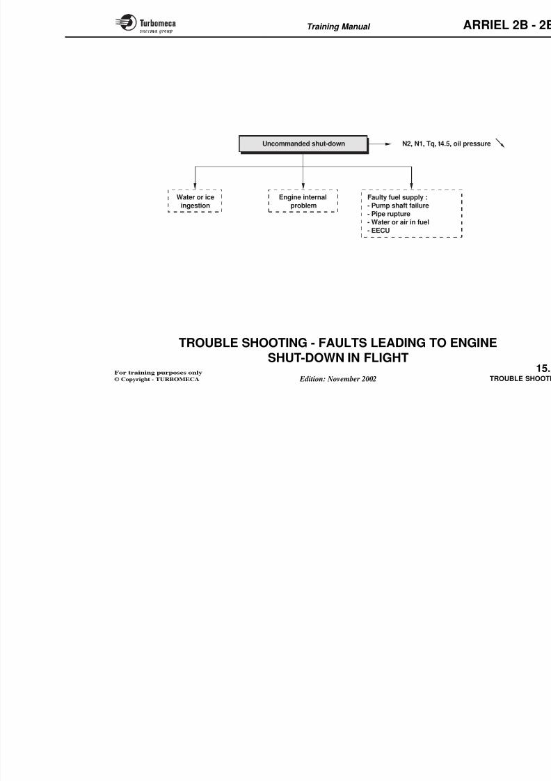
8/13/2019 Arriel_2B-2B1 11-02 En
http://slidepdf.com/reader/full/arriel2b-2b1-11-02-en 400/461
TESTS
DELIVERY
ENGINE
RECEPTION
DISASSEMBLY - REPAIRACCESSORY ASSEMBLY
INVESTIGATION
DISASSEMBLY
ENGINE ASSEMBLY
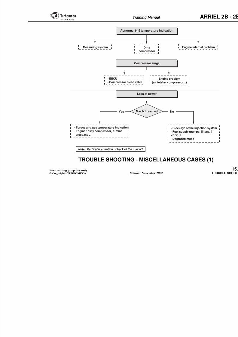
8/13/2019 Arriel_2B-2B1 11-02 En
http://slidepdf.com/reader/full/arriel2b-2b1-11-02-en 401/461
Training Manual ARR
15-TROUBLE SHOOTING
G l 1
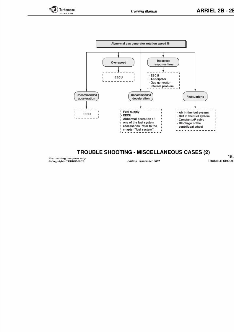
8/13/2019 Arriel_2B-2B1 11-02 En
http://slidepdf.com/reader/full/arriel2b-2b1-11-02-en 402/461
- General .......................................................................... 1
- Trouble shooting ........................................................... 1
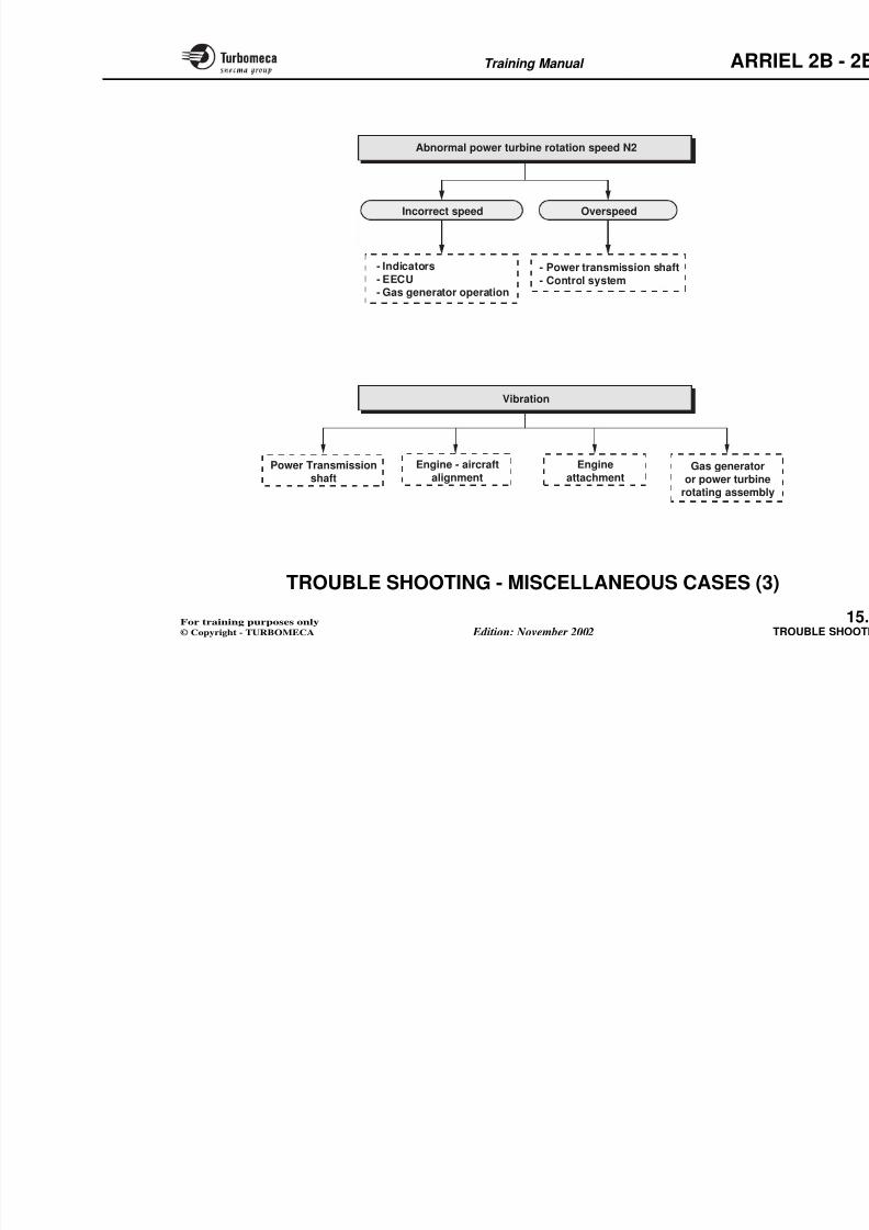
8/13/2019 Arriel_2B-2B1 11-02 En
http://slidepdf.com/reader/full/arriel2b-2b1-11-02-en 403/461
Training Manual ARR
Fault(single, double,
dormant)
Inevitable Random
8/13/2019 Arriel_2B-2B1 11-02 En
http://slidepdf.com/reader/full/arriel2b-2b1-11-02-en 404/461
Symptoms (and other addAll factors should be takeas well as the interaction
Analysis of the fault
Identification of the faulty
Additionalchecks
Deduction
Remed(adjustment replacemen
Or otherperception
Trouble shooting
- Diagnosis
- Remedy
- Repair
- Check
- Adequate means andprocedures
- Training of personnel
MTTR(Mean Time To Repair)
Total time required
for repairing
Training Manual ARR
No effect after selecting start
N doesn't increase
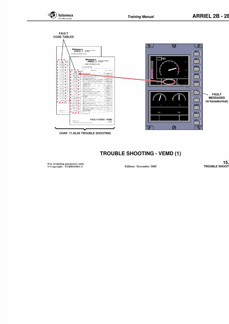
8/13/2019 Arriel_2B-2B1 11-02 En
http://slidepdf.com/reader/full/arriel2b-2b1-11-02-en 405/461
Is crank
possible?
- Starting circuit (circuit breaker,
selector switch, relay …)
- EECU
Yes No
- Starter contactor
- Electrical supply
- Starter
Note : Further tests (failure code, engaging noise of the contactor … ) help locate the failure.
Training Manual ARR
The ignition
system operates(noise of HE components)
On selection of start, N , but no increase in t4.5
Yes No
8/13/2019 Arriel_2B-2B1 11-02 En
http://slidepdf.com/reader/full/arriel2b-2b1-11-02-en 406/461
- Start electro-valve
- Injectors
- HE ignition unit- Igniter plugs
Possible start on1 injector +
1 igniter plug if
on the same side
Fuel
flow
I iti t St t l t
Orfuel supply
Yes No
Note: Refer to the procedure in ordediscriminate
Note: It is also possible to check the fuel flow through the combustion
chamber drain valve.
Training Manual ARR
- EECU- Metering needle- Fuel supply
(LP s stem filters )
Increase due tothe injectors, butthe main system
t4.5 > 200 °Cbut not sufficient
t4.5 too hight4.5 ≈ 200 °C
- EECU- Sensors- Combustion chamberdrain valve
Abnormal t4.5 rise
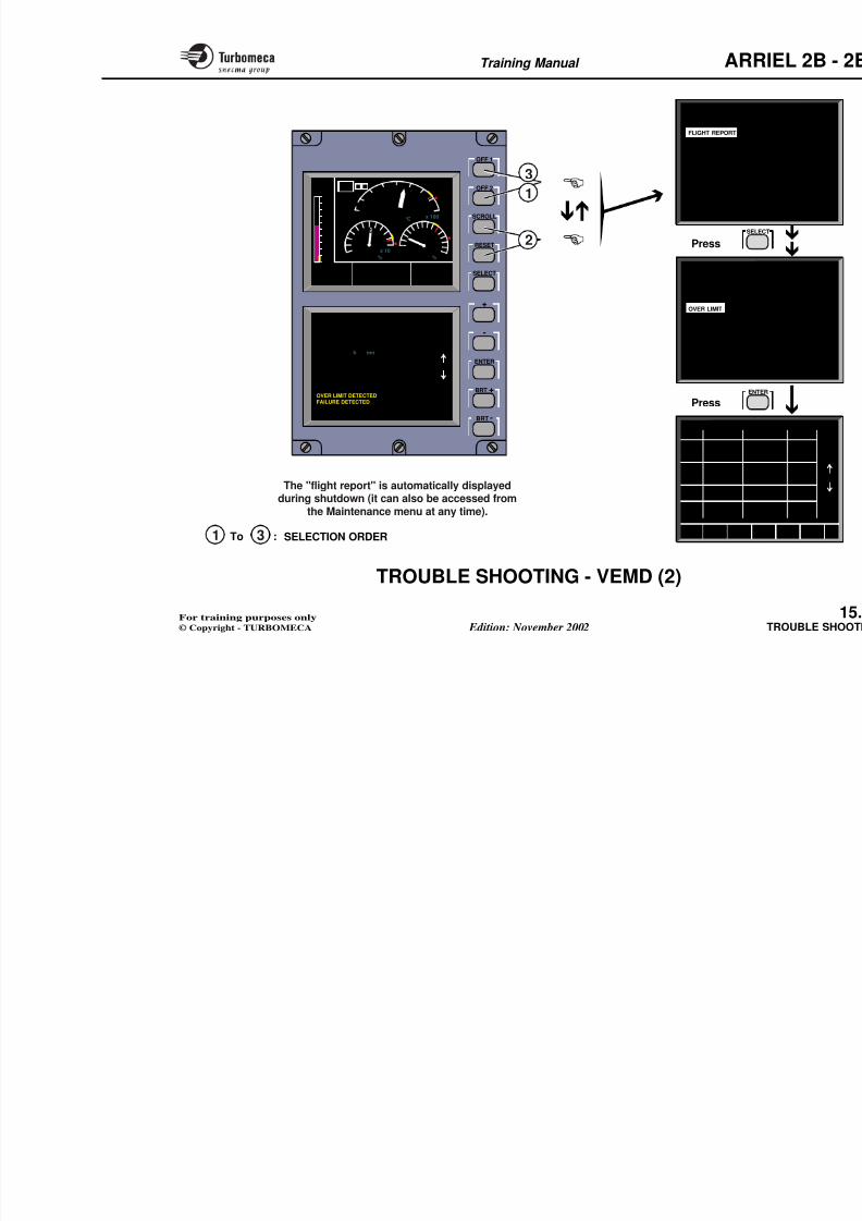
8/13/2019 Arriel_2B-2B1 11-02 En
http://slidepdf.com/reader/full/arriel2b-2b1-11-02-en 407/461
- Pressurising valve- EECU
Failure of the accessory drive shaft
(LP system, filters...)y
is not supplied drain valve
Note : In all cases, check the electrical supply (battery voltage).
Other possibility : N and t4.5 increase, but no start
8/13/2019 Arriel_2B-2B1 11-02 En
http://slidepdf.com/reader/full/arriel2b-2b1-11-02-en 408/461
Training Manual ARR
Deceleration to idle
N1
deceleration
N1 stabilisation -
-
-
Stop selection EECU, ...
Yes
Yes
No
No
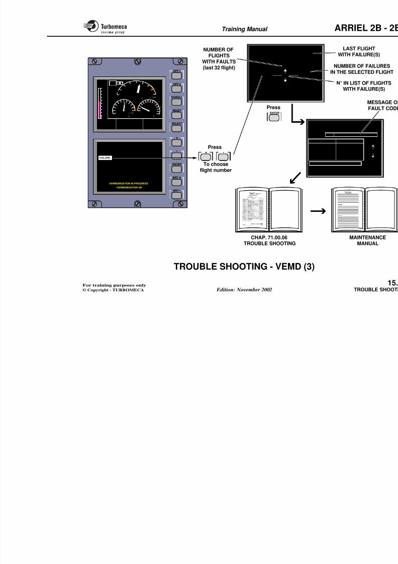
8/13/2019 Arriel_2B-2B1 11-02 En
http://slidepdf.com/reader/full/arriel2b-2b1-11-02-en 409/461
Stop selection EECU, ...
The engine stops
N1 , t4.5
- Fuel system sealing
- Stop / Idle / Flight selector
- Stop electro-valve
Note : Stop is delayed for several
seconds (closing of the metering needle)
Abnormal rubbing of the rotating assemblyNormal
shut-down
Correct
rundown
time
The eng
effected
Further (HP pum
Note: A crank with the power turbine locked ll di i i ti b t th
Yes
Yes No
No
Training Manual ARR
Crank selection
(press and hold)
N1 indication
Note: 2 0 sec. max to avoidstarter overheat
Yes No
8/13/2019 Arriel_2B-2B1 11-02 En
http://slidepdf.com/reader/full/arriel2b-2b1-11-02-en 410/461
Is the
gas generatordriven ?
Accessory
drive trainNormal dry
crank
Does the
starter turn ?
N1 indicationIs startin
possible
Crank
push-button
Yes Yes
Yes
NoNo
Training Manual ARR
Abnormal oil pressure indication
- Oil condition- Seal
VariationNo pressureLow pressure High pressure
- Filter blockageindication
- Measuringsystem
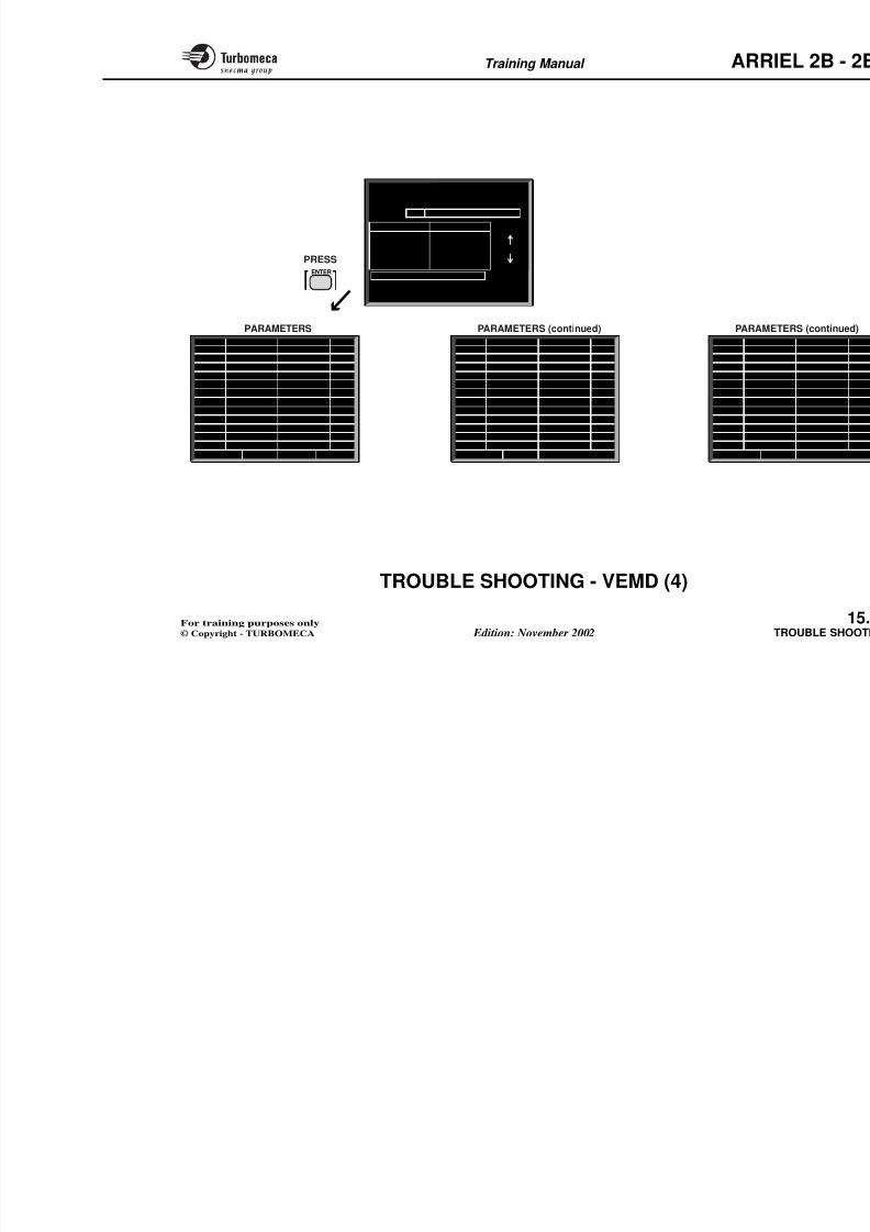
8/13/2019 Arriel_2B-2B1 11-02 En
http://slidepdf.com/reader/full/arriel2b-2b1-11-02-en 411/461
- Failure of the pump shaft- Pressure relief valve- Blockage inside the system- Large internal or external
leak
Pressure indicatingsystem :- Transmitter- Indicator
Low oilpressure lightilluminated ?
- Blockage insidethe system
- Oil pressuretransmitter
- Pump pressurerelief valve
- Blockage ofa jet
Yes No
Training Manual ARR
Abnormal oil temperature indication
HighLow
- Measuring system- Insufficient cooling- Insufficient lubrication,
Measuring system
8/13/2019 Arriel_2B-2B1 11-02 En
http://slidepdf.com/reader/full/arriel2b-2b1-11-02-en 412/461
Insufficient lubrication,blockage of a jet
Note : Fuel dilution in thheat exchanger i
Oil contaminat
Detection
Acorco
- Magnetic plug- Analysis- Color, aspect
Abnormal oil consumption
Visibleleak
Yes No
External leak
Pipe or accessoryseal on casing
Internal leak
Leak from cold sectionlabyrinth seals (frontsection) :Contamination of theaircraft air bleed
Leak from hot sectionlabyrinth seals (rearsection) : Smoke and oilevidence in the exhaustpipe
Training Manual ARR
Uncommanded shut-down N2, N1, Tq, t4.5, oil pressure
8/13/2019 Arriel_2B-2B1 11-02 En
http://slidepdf.com/reader/full/arriel2b-2b1-11-02-en 413/461
Engine internal
problem
Faulty fuel supply :
- Pump shaft failure
- Pipe rupture
- Water or air in fuel
- EECU
Water or ice
ingestion
Training Manual ARR
Abnormal t4.5 temperature indication
Compressor surge
Dirtycompressor Engine internal problMeasuring system
8/13/2019 Arriel_2B-2B1 11-02 En
http://slidepdf.com/reader/full/arriel2b-2b1-11-02-en 414/461
Max N1 reached
Loss of power
Engine problem
(air intake, compressor...)
- Blockage of the injection sys
- Fuel supply (pumps, filters..
- EECU
- Degraded mode
- Torque and gas temperature indication
- Engine : dirty compressor, turbine
creep,etc ...
Yes No
- EECU
- Compressor bleed valve
Training Manual ARR
Incorrectresponse time
Overspeed
Abnormal gas generator rotation speed N1
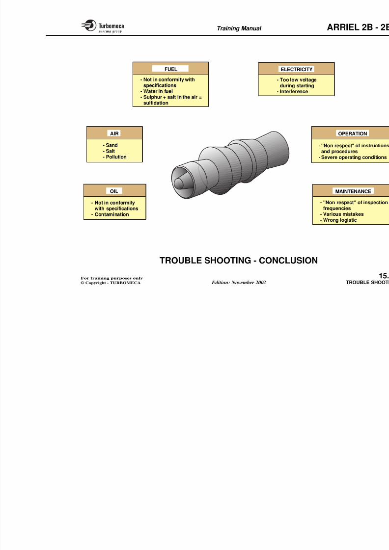
8/13/2019 Arriel_2B-2B1 11-02 En
http://slidepdf.com/reader/full/arriel2b-2b1-11-02-en 415/461
Fluctuations
- Air in the fuel system
- Dirt in the fuel syste- Constant ∆P valve- Blockage of the
centrifugal wheel
EECU
EECU
Uncommanded
deceleration
- Fuel supply- EECU- Abnormal operation of
one of the fuel systemaccessories (refer to the
chapter "fuel system")
- EECU
- Anticipator- Gas generator
internal problem
Uncommanded
acceleration
Training Manual ARR
Abnormal power turbine rotation speed N2
Overspeed
- Power transmission shaft
Incorrect speed
- Indicators
8/13/2019 Arriel_2B-2B1 11-02 En
http://slidepdf.com/reader/full/arriel2b-2b1-11-02-en 416/461
Power transmission shaft
- Control system
Indicators
- EECU
- Gas generator operation
Vibration
Gas generator
or power turbinerotating assembl
Engine
attachmentPower Transmission
shaft
Engine - aircraft
alignment
Training Manual ARR
TROUBLE SHOOTING - VEMD (1)
The VEMD includes a maintenance aid facility to helpwith trouble shooting.
Faults
Faults detected by the EECU are transmitted to the VEMDwhich displays them on the lower part of the upper screen.This display is in the form:
FAIL 1 XXXX or FAIL 2 XXXX
F il 1 d F il 2 f t th f lt d t bl i Ch t
8/13/2019 Arriel_2B-2B1 11-02 En
http://slidepdf.com/reader/full/arriel2b-2b1-11-02-en 417/461
Fail 1 and Fail 2 refer to the fault code tables in Chapter71.00.06 trouble shooting (Maintenance manual). Thesetables identify the fault related to each code.
Training Manual ARR
SCROLL
OFF 2
OFF 1
768
9
10
11
5
P2
43
2
15
10
NG
98 %
T4
680 °C
FAULTCODE TABLES
8/13/2019 Arriel_2B-2B1 11-02 En
http://slidepdf.com/reader/full/arriel2b-2b1-11-02-en 418/461
BRT -
BRT +
ENTER
-
+
SELECT
RESET
5 10
160
TEMP90 °C
x 10
68
102
4
0
PRESS6 Bar
U/BUS28 V
I/GEN150 A
16
ENG OIL
F L I
MESSAGES
1110
0
OAT
+ 25.1 °C
FUEL QTY
210 KG
TQ
90 %
FAULT CODES - VEMD
CHAP. 71.00.06 TROUBLE SHOOTING
Training Manual ARR
TROUBLE SHOOTING - VEMD (2)
Flight Report
The "FLIGHT REPORT" is automatically displayed duringshut-down. It can also be accessed from the Maintenance
menu at any time. Up to 32 records can be stored inmemory. In the event of problem being detected, the FlightReport will include one or both of the following messages:
OVERLIMIT DETECTEDFAILURE DETECTED
Over Limit
The Over Limit page records any oN1, N2 and NR. It displays the durat
excess.
8/13/2019 Arriel_2B-2B1 11-02 En
http://slidepdf.com/reader/full/arriel2b-2b1-11-02-en 419/461
To see the details of an overlimit or failure proceed as
follows:
- Switch off the VEMD screens by pressing "OFF 1"
and "OFF 2.
- Depress and keep depressed the "SCROLL" and
"RESET" buttons.
- Depress the buttons OFF 1 and OFF 2.
The screens display the message "TEST IN PROGRESS"followed by "RELEASE KEYS" followed by theMaintenance Menu on the lower screen.
Use the "SELECT" button to highlight a subject and the"ENTER" button to display its page
1
3
2
8/13/2019 Arriel_2B-2B1 11-02 En
http://slidepdf.com/reader/full/arriel2b-2b1-11-02-en 420/461
Training Manual ARR
TROUBLE SHOOTING - VEMD (3)
Failure Diagnosis
The failure diagnosis is given on 5 pages.
"FAILURE DIAGNOSIS" page :
Displays all the faults in the memory for the last 32 flights.It includes :
- The total number of flights with failures detected
At last the "fault finding tree" inditasks ; maintenance tasks describedmanual.
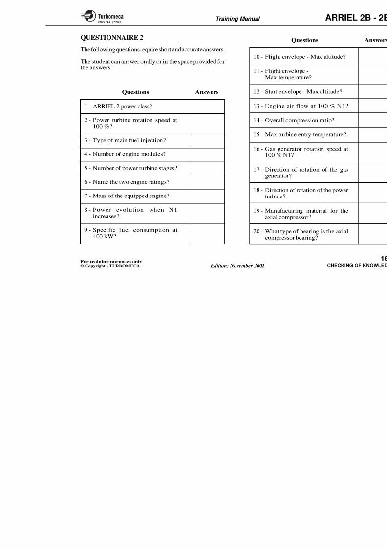
8/13/2019 Arriel_2B-2B1 11-02 En
http://slidepdf.com/reader/full/arriel2b-2b1-11-02-en 421/461
- The flight number with number of failures detected
- The number in the list of flights with failures.
Use the "+" and "-" buttons to scroll through the flights,then the "ENTER" button to see the details of the flightselected.
"COMPLETE DIAGNOSIS" page :
Displays the flight details and the accessory identification,plus a fault code which can be decoded in chap. 71.00.06Trouble shooting. To each fault code corresponds a task number. To the task number corresponds a "fault findingtree".
Training Manual ARR
SELECT
RESET
SCROLL
OFF 2
OFF 1
0
5
10
NG
T4
TQ
648 °C
61,8 % 72,7 %
5 64
3
0
78
9
x 100
x 10
2
0
4
10
8
6
-10
-5
5
0
P2
ENTER
FLIGHT XXXXX
FLIGHTXXXXX
Nb FAILXXX
FAILURE DIAGNOSIS
EXIT ----> PRESS RESET
XXX
XXX
1
COMPLETE DIAGN
NUMBEIN THE SE
LASWITH
N° IN LWIT
NUMBER OFFLIGHTS
WITH FAULTS(last 32 flight)
Press
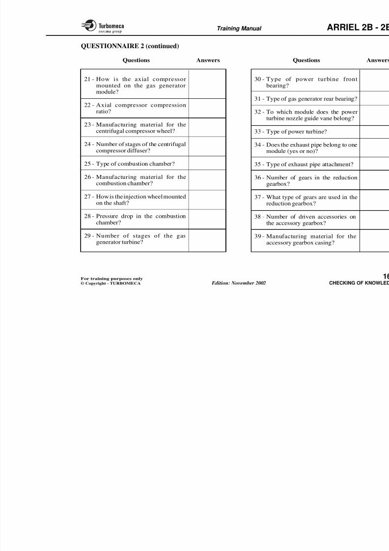
8/13/2019 Arriel_2B-2B1 11-02 En
http://slidepdf.com/reader/full/arriel2b-2b1-11-02-en 422/461
BRT -
BRT +
ENTER
-
+
MAINTENANCE MENU
FLIGHT REPORT
FAILURE
OVER LIMIT
ENGINE POWER CHECK
TRANS. RESET
FUNC. TIMES
FADEC DATA
HARMONISATION IN PROGRESS
HARMONISATION OK
-+
TASK
COMPLETE DIAGN
FAIL on FLIGHT XXXXX at X XX
TEST REF XXX
Param EOP
To see param press ENTER
EXIT
EOPFAIL
LRU name LRU na
XXXXXXXXXXXXXXXXXXXXXXXXXXXXXXXXXXXXXXXX
XXXXXXXXXXXXXXXXXXXXXXXXXXXXXXXXXXXXXXXXXXXXXXXXXXXX
CHAP 71 00 06 M
To chooseflight number
Press
Training Manual ARR
TROUBLE SHOOTING - VEMD (4)
Failure Diagnosis (cont.)
"PARAMETERS" pages:
The Parameters pages of the fault diagnosis display theengine parameters. They can be accessed by pressing the"Enter" button when on the complete diagnosis page.
The parameters are on 3 pages which will be displayedautomatically (one or several) according to the faultsdetected.
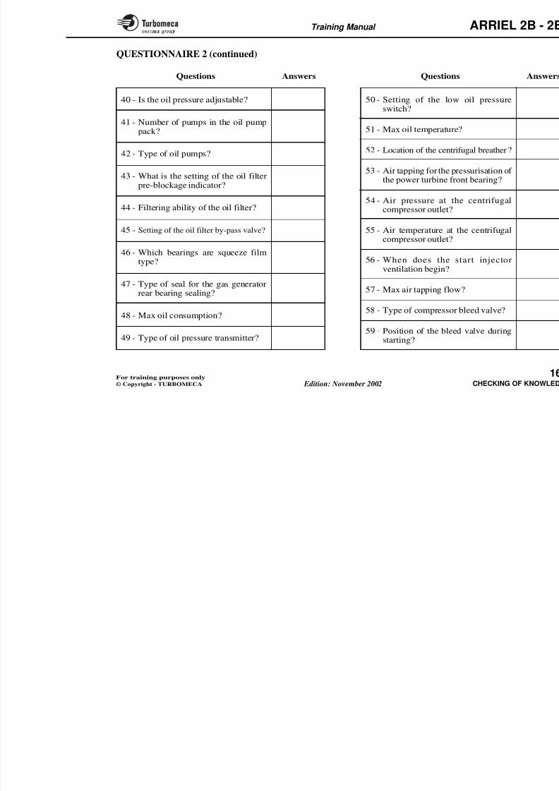
8/13/2019 Arriel_2B-2B1 11-02 En
http://slidepdf.com/reader/full/arriel2b-2b1-11-02-en 423/461
detected.
The values of each parameter are given in 2 columns. Thefirst column (left) shows the values 12 seconds before thefailure and the second column (right) shows the valueswhen the fault was detected.
Training Manual ARR
COMPLETE DIAGNOSIS
FAIL on FLIGHT XXXXX at X XX XX
TEST REF XXX
P EOP
FAIL
1
-
+
XXX
XXX
R
EOPFAIL
LRU name LRU name
XXXXXXXXXXXXXXXXXXXXXXXXXXXXXXXXXXXXXXXXXXXXXXXXXXXXXXXXXXXXXXXXX
XXXXXXXXXXXXXXXXXXXXXXXXXXXXXXXXXXXXXXXXXXXXXXXXXXXX
PRESSENTER
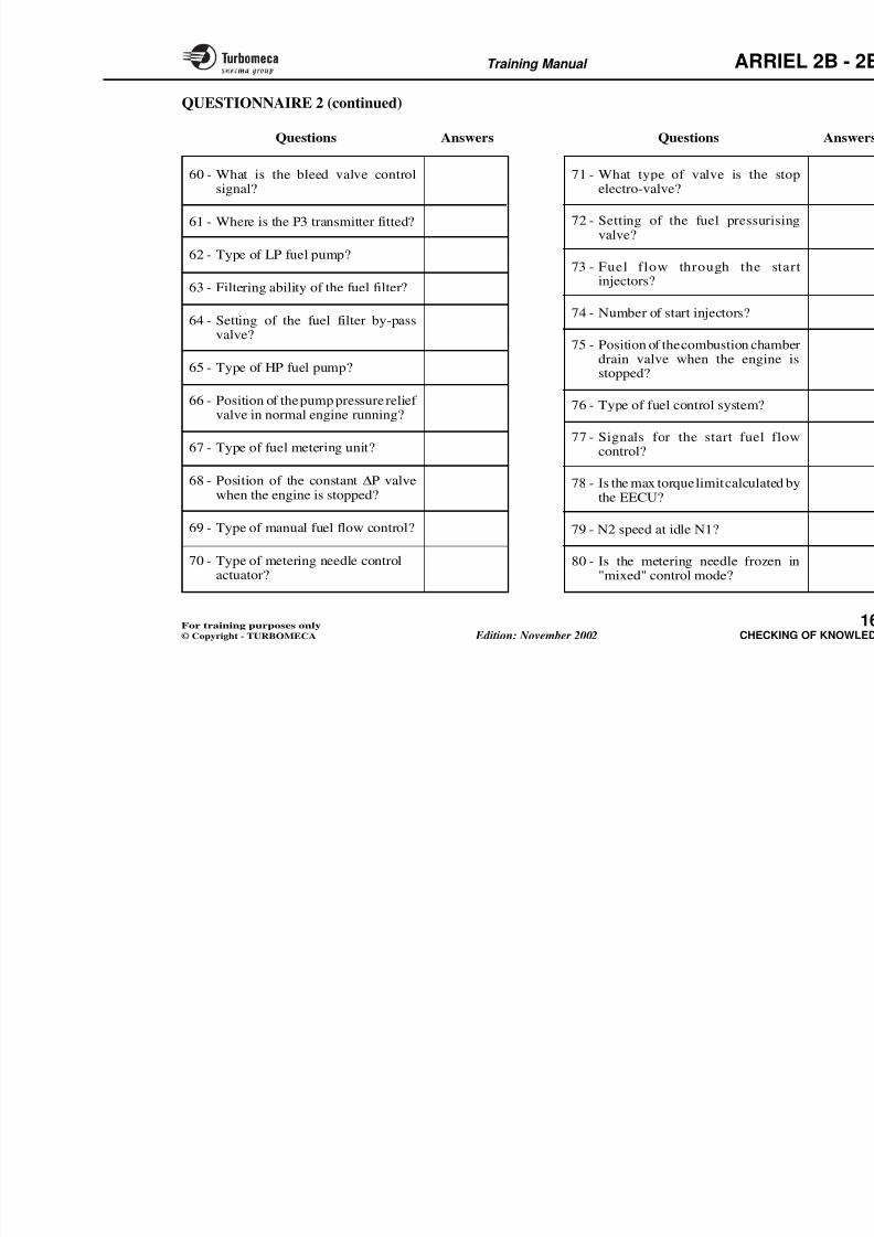
8/13/2019 Arriel_2B-2B1 11-02 En
http://slidepdf.com/reader/full/arriel2b-2b1-11-02-en 424/461
Param EOP
To see param press ENTER
EXIT ----> PRESS RESET
R
XX FAIL
NG
TRQ
t4
T4R1
T4R2
P0
OAT
I. GENCU. BUS
NF
NR
VZ
XXX.X
XXX.X
XXX
XXXXX.X
XXXXX.X
XXXXX
-XX.X
XXXXX.X
XXXXX
XXX
-XXXX
XXX.X
XXX.X
XXX
XXXX.X
XXXX.X
XXXXX
-XX.X
-XXXXX.X
XXXXX
XXX
-XXXX
%
%
°C
Ω
Ω
mb
°C
AV
RPM
RPM
Ft / mn
P2 HD/P/DFAIL BOOLEANX/X/X X/X/X
XX FAIL
EOP
EOT
FQ
FT
FF
SUNG
OAT
XXX.X
XXX.X
XXX
XXXX.X
XXXX.X
XXXXX
XX.X
XXX.X
XXX.X
XXX
XXXX.X
XXXX.X
XXXXX
XX.X
X
NG
NG F.
TRQ F.
t4
T4 F.
NF
NF F.
FAIL 1FAIL 2
OUT 1
OUT 2
IN
XX
XX
XX
X
X
XX
XX
XXXX
XX
XX
XX
bar
°C
Kg
°C
Kg / h
Kg
°C
PARAMETERS PARAMETERS (continued) PARAM
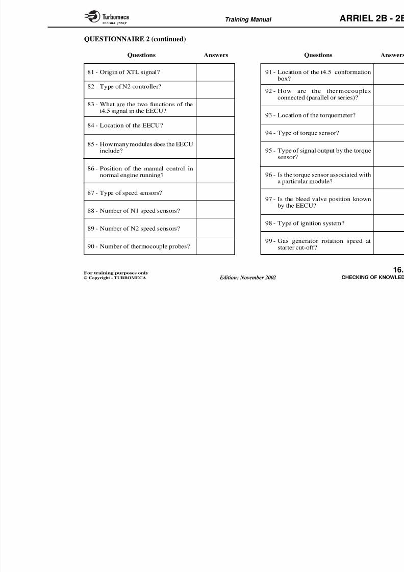
8/13/2019 Arriel_2B-2B1 11-02 En
http://slidepdf.com/reader/full/arriel2b-2b1-11-02-en 425/461
Training Manual ARR
ARRIEL2B-2B1
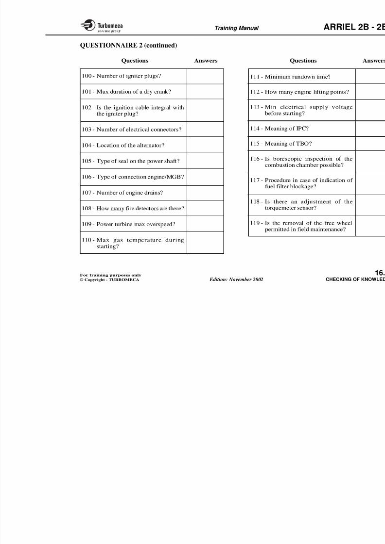
8/13/2019 Arriel_2B-2B1 11-02 En
http://slidepdf.com/reader/full/arriel2b-2b1-11-02-en 426/461
2B-2B1
CHAP. 71.00.06TROUBLE
SHOOTING
MAINTENANCEMANUAL
Trouble shootingtasks
Faultcodes
Maintenancefaults
Operatingfaults
Training Manual ARR
TROUBLE SHOOTING - CONCLUSION
Despite the high reliability of the product, failures remaininevitable and happen at random. But their rate and effectscan be reduced if the "enemies" of the engine are taken intoconsideration.
When the failure occurs, you have to be in a position tocorrect it.
"Enemies" of the engine
The traditional adverse conditions for this type of engineare :
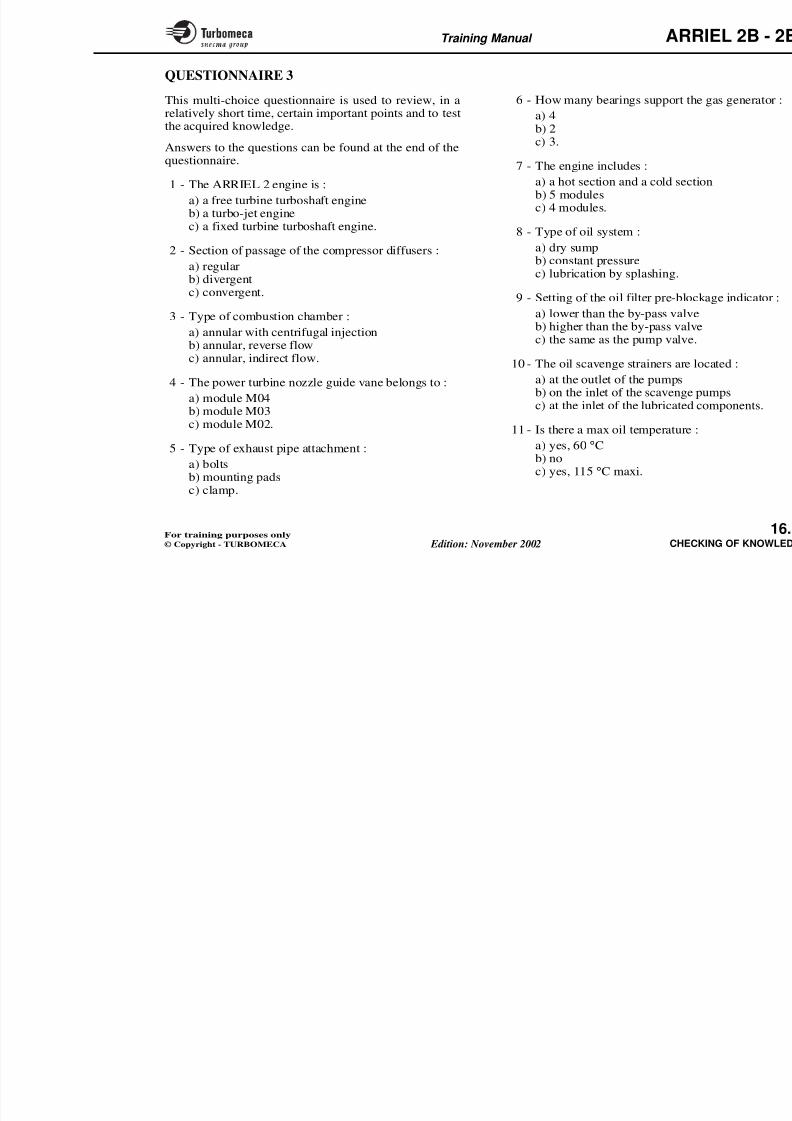
8/13/2019 Arriel_2B-2B1 11-02 En
http://slidepdf.com/reader/full/arriel2b-2b1-11-02-en 427/461
are :
- Supply (oil, air, fuel, electricity)
• Oil - Not in conformity with spec., contamination
• Air - Sand, salt, pollution
• Fuel - Not in conformity with spec., contamination
• Electricity - Low voltage, connectors.
- Operation ("non respect" of instructions and procedures)
- Maintenance ("non respect" of inspection frequencies,and of the strict application of the procedures).
Training Manual ARR
- Too low voltageduring starting
- Interference
FUEL
- Not in conformity withspecifications
- Water in fuel- Sulphur + salt in the air =
sulfidation
ELECTRICITY

8/13/2019 Arriel_2B-2B1 11-02 En
http://slidepdf.com/reader/full/arriel2b-2b1-11-02-en 428/461
- Not in conformitywith specifications
- Contamination
MAI
AIR OP
- "Non respand proce
- Severe op
- "Non resfrequenc
- Various m- Wrong lo
- Sand- Salt- Pollution
OIL
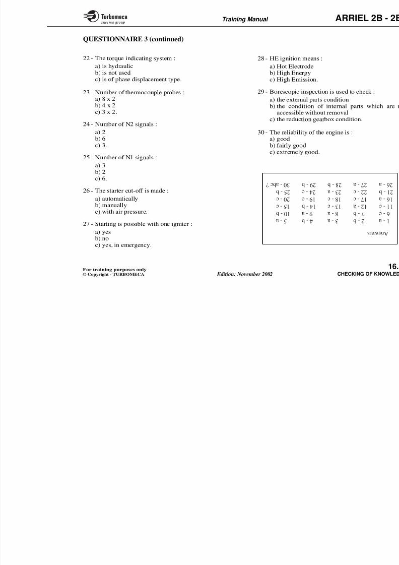
8/13/2019 Arriel_2B-2B1 11-02 En
http://slidepdf.com/reader/full/arriel2b-2b1-11-02-en 429/461
Training Manual ARR
16-CHECKING OF KNOWLE- Introduction .................................................................. 1
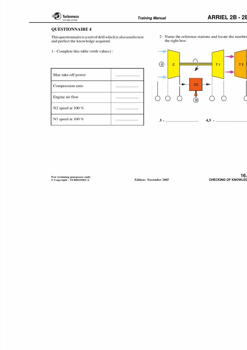
8/13/2019 Arriel_2B-2B1 11-02 En
http://slidepdf.com/reader/full/arriel2b-2b1-11-02-en 430/461
- Questionnaire 1 ............................................................. 1
- Questionnaire 2 ............................................................. 1
- Questionnaire 3 ............................................................. 1
- Questionnaire 4 .............................................................. 1
Training Manual ARR
INTRODUCTION
Method
Continuous checking helps to ensure the information isassimilated. It is more a method of work than a testing inthe traditional sense.
Objectives of the questionnaires
The questionnaires permit a progressive assimilation anda long term retention. The questionnaires are a subject fordiscussion (effects of group dynamics). They also permitstudents to consider important subjects several times un-
Types of questionnaires
Several types of questionnaire can bcourse :
- Traditional written questionnaire
- "Short answer" questionnaire
- Multi Choice Questionnaire (MCQ
- Oral questionnaire
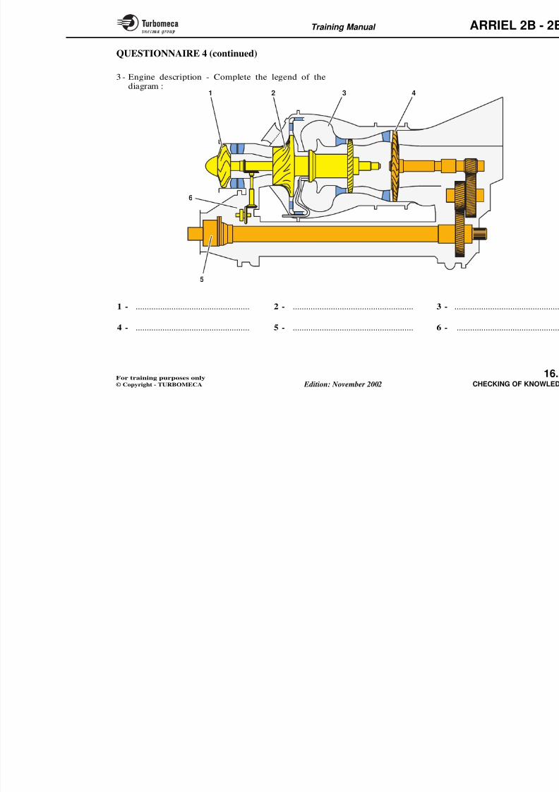
8/13/2019 Arriel_2B-2B1 11-02 En
http://slidepdf.com/reader/full/arriel2b-2b1-11-02-en 431/461
p jder different aspects.
Integration into the training programme
- First hour every day for revision of the subjects previ-ously studied
- After each chapter (or module) of the course
- At the end of the training course.
- Learning Through Teaching (LTTexplain a given subject).
Examination
The final examination at the end of ththree tests : written, oral and practicalapproval card are given to the studesatisfactory.
Training Manual ARR
QUESTIONNAIRE 1
This traditional questionnaire is established according tothe same plan as the training manual in which the answerscan be found.
Power plant
1 - List the main functional components of the powerplant.
2 - Explain the thermodynamic operation of the engine.
3 - State the following features (at take-off, in standard
Engine
1 - List the main components of th
2 - State the following characterist• Compression ratio
• Turbine entry temperature
• N2 speed at 100 %
• N1 speed at 100 %
3 D ib h bi
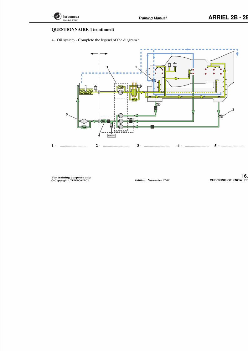
8/13/2019 Arriel_2B-2B1 11-02 En
http://slidepdf.com/reader/full/arriel2b-2b1-11-02-en 432/461
atmosphere) :
• Power on the shaft
• Output shaft rotation speed
• Mass of the engine with specific equipment
• Main overall dimensions of the power plant
4 - Explain the principle of engine adaptation to helicopter
power requirements.5 - Give a definition of the operating ratings.
3 - Describe the power turbine asse
4 - Describe the fuel injection syst
5 - List the engine driven accessor
6 - List the bearings which support
7 - Describe the system used for be
8 - Describe the modular construct
9 - Describe the engine air intake.
10 - List the manufacturing materialcomponents.
Training Manual ARR
QUESTIONNAIRE 1 (continued)
Oil system
1 - Explain the general operation of the oil system.
2 - Describe the oil filter assembly.
3 - State the location of strainers and magnetic plugs.4 - What is the purpose of the check valve ?
5 - How many magnetic plugs are there on the engine ?
Air system
1 - List the functions ensured by the internal air system
Control system
1 - List the main functions of the co
2 - Explain the basic principle of the
3 - Explain the operating principle o
4 - List the components of the EnginUnit.
5 - List the logic input signals of the
6 - List the analog input signals of th
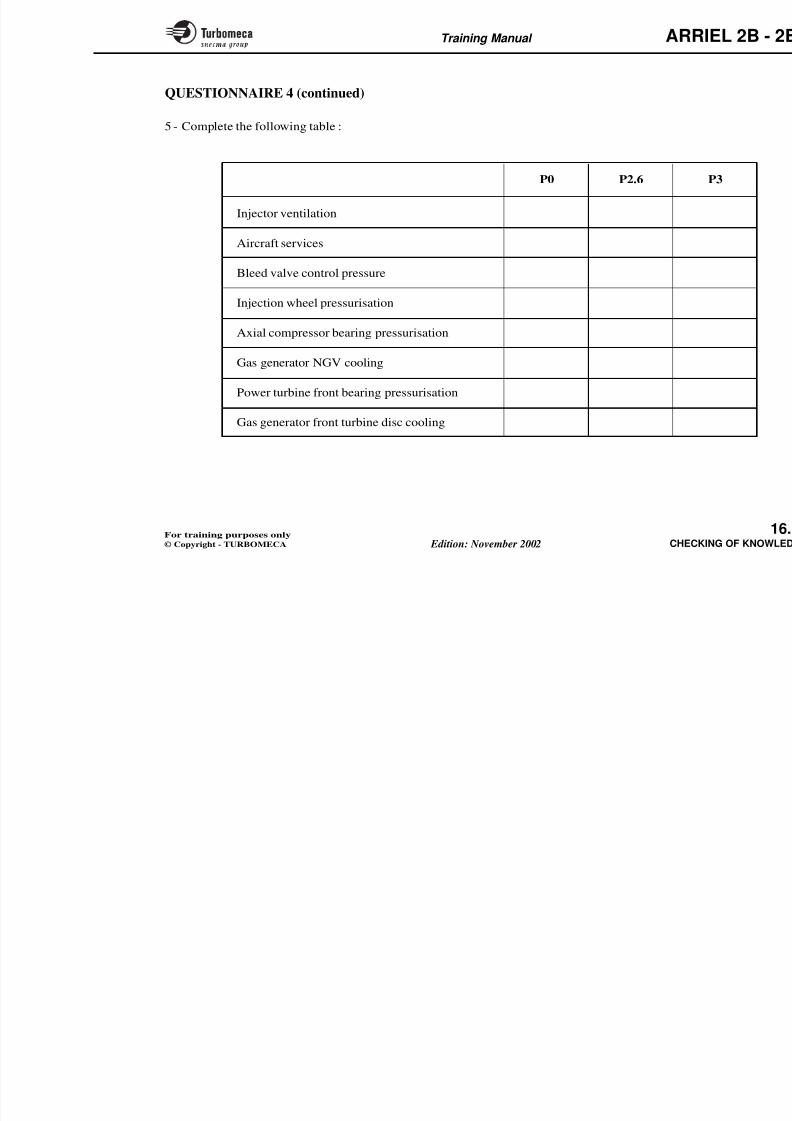
8/13/2019 Arriel_2B-2B1 11-02 En
http://slidepdf.com/reader/full/arriel2b-2b1-11-02-en 433/461
1 List the functions ensured by the internal air system
(secondary system).2 - List the function of the various air tappings.
3 - Why are the start injectors ventilated ?
4 - Explain the purpose and the operation of the compressorbleed valve.
Fuel system
1 - What type of fuel system is it.
2 - Describe the HP fuel pump.
3 - Describe the fuel metering unit.
4 - What is the purpose of the constant ∆P valve.
5 - Explain the principle of fuel injection (main and startinginjection).
7 - Describe and explain the operatioselector.
8 - Describe the Engine Electronic C
Measurement and indicating sys
1 - List the various measurement and
2 - Describe the power turbine speeindicating system.
3 - Explain the operating principlesystem.
4 - Describe the gas temperatureindicating system.
5 - What is the purpose of the torqu
Training Manual ARR
QUESTIONNAIRE 1 (continued)
Starting
1 - Describe the cranking function of the engine.
2 - Describe the ignition system (ignition unit and igniterplugs).
3 - List the main phases of the starting cycle.
Electrical system
1 D ib th l t i l h d t
Limitations and engine handling
1 - List the main operating limitatio
2 - Describe the engine dry crank pr
Various aspects of maintenance
1 - List the main practices of a perio
2 - List the methods used for "on co
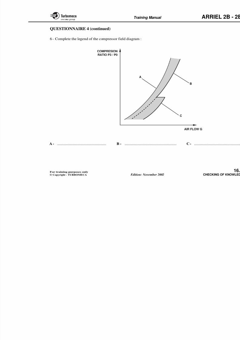
8/13/2019 Arriel_2B-2B1 11-02 En
http://slidepdf.com/reader/full/arriel2b-2b1-11-02-en 434/461
1 - Describe the electrical harnesses and connectors.
2 - Describe the alternator.
Engine installation
1 - Describe the attachment of the engine to the aircraft.
2 - Describe the engine power drive and the powertransmission.
3 - List the various engine / aircraft interfaces.
4 - Describe the fire protection system of the engine.
3 - List the technical publicationmaintenance.
Maintenance procedures
1 - Describe the compressor cleanin
2 - Name the LRUs of the air system
3 - Explain the attachment of each o
Trouble shooting
1 - Carry out the trouble shooting ex
Training Manual ARR
Questions
1 - ARRIEL 2 power class?
2 - Power turbine rotation speed at100 %?
10 - Flight envelope - Max altitude
11 - Flight envelope -
Max temperature?
12 - Start envelope - Max altitude?
13 - Engine air flow at 100 % N
14 - Overall compression ratio?
QUESTIONNAIRE 2
The following questions require short and accurate answers.
The student can answer orally or in the space provided forthe answers.
Questions Answers
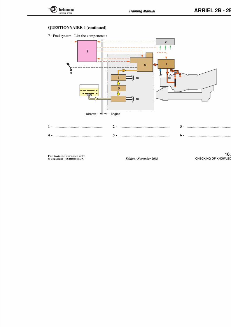
8/13/2019 Arriel_2B-2B1 11-02 En
http://slidepdf.com/reader/full/arriel2b-2b1-11-02-en 435/461
100 %?
3 - Type of main fuel injection?
4 - Number of engine modules?
5 - Number of power turbine stages?
6 - Name the two engine ratings?
7 - Mass of the equipped engine?
8 - Power evolution when N1increases?
9 Specific fuel consumption at
15 - Max turbine entry temperature
16 - Gas generator rotation speed 100 % N1?
17 - Direction of rotation of the ggenerator?
18 - Direction of rotation of the powturbine?
19 - Manufacturing material for taxial compressor?
20 Wh f b i i h
Training Manual ARR
30 - Type of power turbine fbearing?
31 - Type of gas generator rear bea
32 - To which module does the pturbine nozzle guide vane belo
21 - How is the axial compressormounted on the gas generatormodule?
22 - Axial compressor compressionratio?
23 - Manufacturing material for the
QUESTIONNAIRE 2 (continued)
Questions Answers Questions
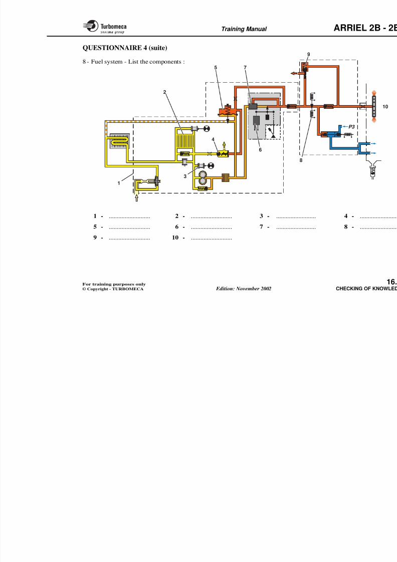
8/13/2019 Arriel_2B-2B1 11-02 En
http://slidepdf.com/reader/full/arriel2b-2b1-11-02-en 436/461
33 - Type of power turbine?
34 - Does the exhaust pipe belong tmodule (yes or no)?
35 - Type of exhaust pipe attachme
36 - Number of gears in the redu
gearbox?
37 - What type of gears are used ireduction gearbox?
38 - Number of driven accessoriethe accessory gearbox?
23 Manufacturing material for the
centrifugal compressor wheel?
24 - Number of stages of the centrifugalcompressor diffuser?
25 - Type of combustion chamber?
26 - Manufacturing material for the
combustion chamber?
27 - How is the injection wheel mountedon the shaft?
28 - Pressure drop in the combustionchamber?
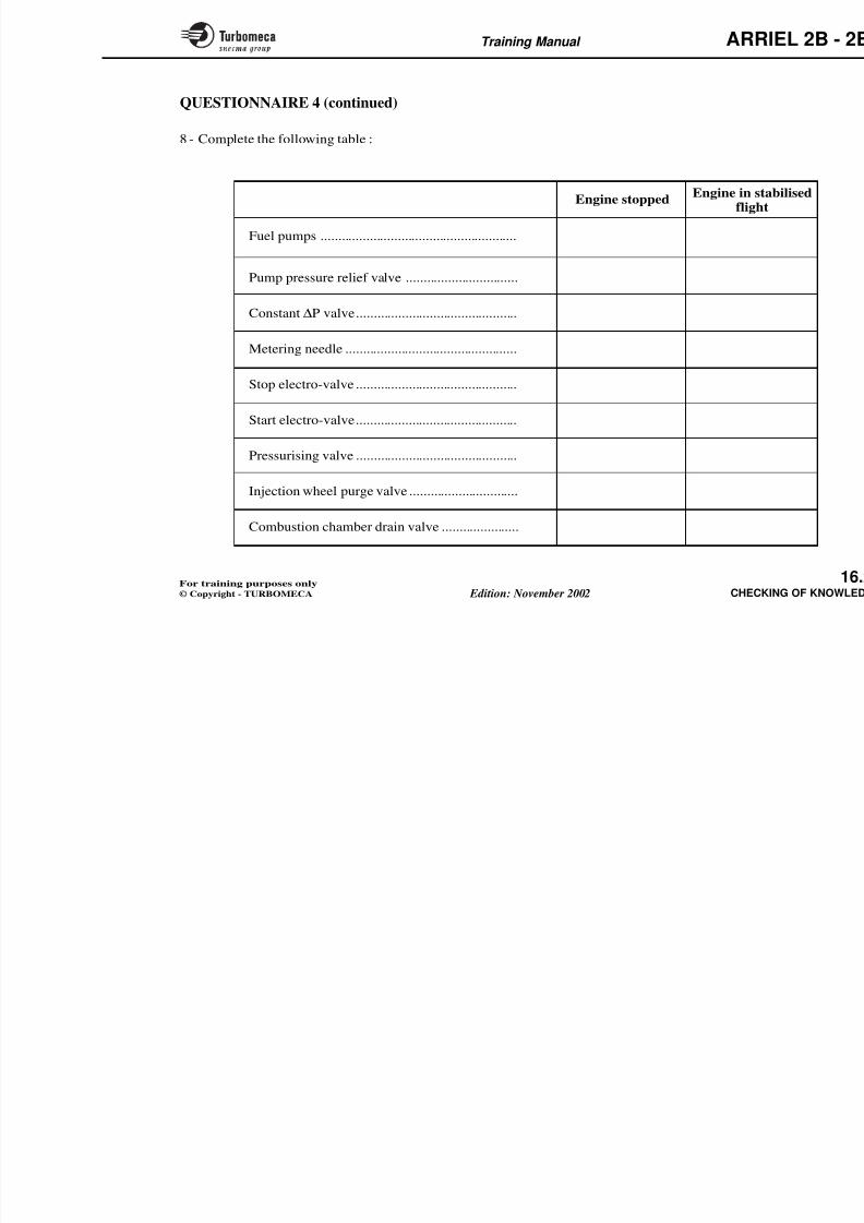
8/13/2019 Arriel_2B-2B1 11-02 En
http://slidepdf.com/reader/full/arriel2b-2b1-11-02-en 437/461
Training Manual ARR
60 - What is the bleed valve controlsignal?
61 - Where is the P3 transmitter fitted?
62 - Type of LP fuel pump?
63 Filt i bilit f th f l filt ?
QUESTIONNAIRE 2 (continued)
Questions Answers Questions
71 - What type of valve is the electro-valve?
72 - Setting of the fuel pressurivalve?
73 - Fuel flow through the injectors?
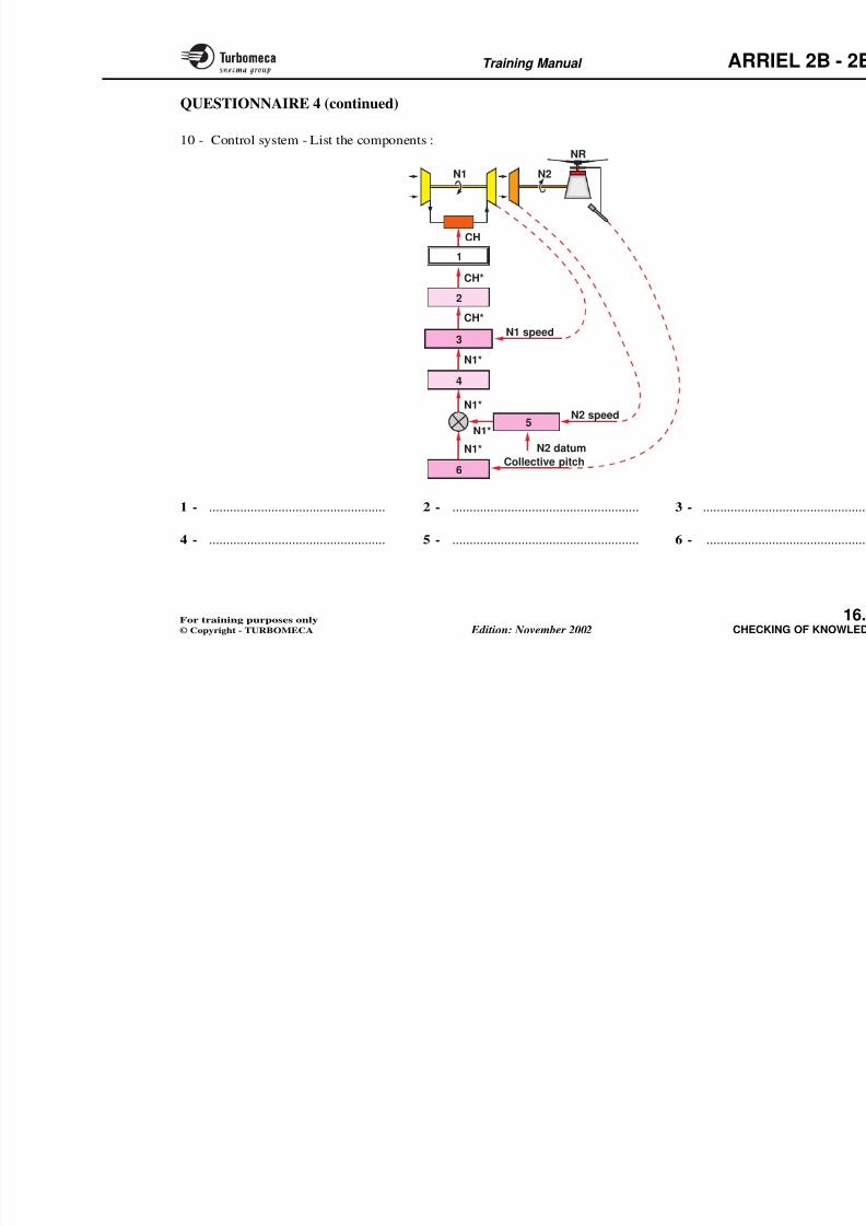
8/13/2019 Arriel_2B-2B1 11-02 En
http://slidepdf.com/reader/full/arriel2b-2b1-11-02-en 438/461
63 - Filtering ability of the fuel filter?
64 - Setting of the fuel filter by-passvalve?
65 - Type of HP fuel pump?
66 - Position of the pump pressure relief
valve in normal engine running?
67 - Type of fuel metering unit?
68 - Position of the constant ∆P valvewhen the engine is stopped?
injectors?
74 - Number of start injectors?
75 - Position of the combustion chamdrain valve when the enginstopped?
76 - Type of fuel control system?
77 - Signals for the start fuel fcontrol?
78 - Is the max torque limit calculatethe EECU?
Training Manual ARR
91 - Location of the t4.5 conformbox?
92 - How are the thermocouconnected (parallel or series)?
93 - Location of the torquemeter?
94 T f t ?
81 - Origin of XTL signal?
82 - Type of N2 controller?
83 - What are the two functions of thet4.5 signal in the EECU?
84 - Location of the EECU?
QUESTIONNAIRE 2 (continued)
Questions Answers Questions
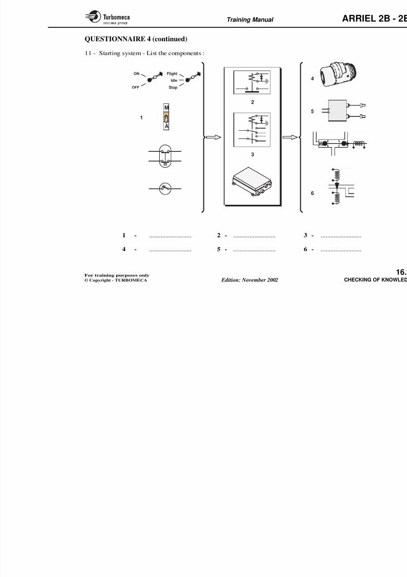
8/13/2019 Arriel_2B-2B1 11-02 En
http://slidepdf.com/reader/full/arriel2b-2b1-11-02-en 439/461
94 - Type of torque sensor?
95 - Type of signal output by the tosensor?
96 - Is the torque sensor associateda particular module?
97 - Is the bleed valve position knby the EECU?
98 - Type of ignition system?
99 G t t ti
85 - How many modules does the EECUinclude?
86 - Position of the manual control innormal engine running?
87 - Type of speed sensors?
88 - Number of N1 speed sensors?
89 - Number of N2 speed sensors?
Training Manual ARR
111 - Minimum rundown time?
112 - How many engine lifting poin
113 - Min electrical supply volbefore starting?
100 - Number of igniter plugs?
101 - Max duration of a dry crank?
102 - Is the ignition cable integral withthe igniter plug?
QUESTIONNAIRE 2 (continued)
Questions Answers Questions
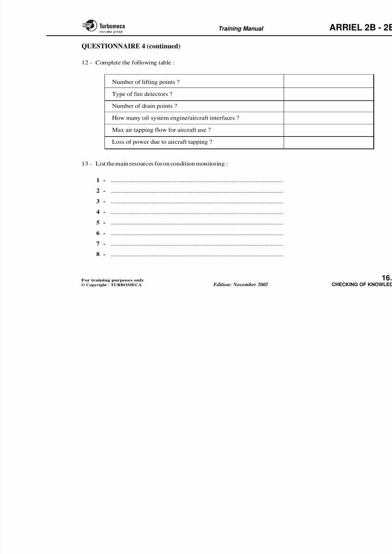
8/13/2019 Arriel_2B-2B1 11-02 En
http://slidepdf.com/reader/full/arriel2b-2b1-11-02-en 440/461
114 - Meaning of IPC?
115 - Meaning of TBO?
116 - Is borescopic inspection ofcombustion chamber possible
117 - Procedure in case of indicatiofuel filter blockage?
118 - Is there an adjustment oftorquemeter sensor?
119 - Is the removal of the free witt d i fi ld i t
103 - Number of electrical connectors?
104 - Location of the alternator?
105 - Type of seal on the power shaft?
106 - Type of connection engine/MGB?
107 - Number of engine drains?
108 - How many fire detectors are there?
109 - Power turbine max overspeed?
Training Manual ARR
QUESTIONNAIRE 3
This multi-choice questionnaire is used to review, in arelatively short time, certain important points and to testthe acquired knowledge.
Answers to the questions can be found at the end of the
questionnaire.
1 - The ARRIEL 2 engine is :
a) a free turbine turboshaft engineb) a turbo-jet enginec) a fixed turbine turboshaft engine.
2 - Section of passage of the compressor diffusers :
6 - How many bearings support the
a) 4b) 2c) 3.
7 - The engine includes :a) a hot section and a cold sectib) 5 modulesc) 4 modules.
8 - Type of oil system :
a) dry sumpb) constant pressure
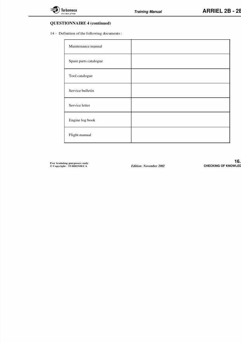
8/13/2019 Arriel_2B-2B1 11-02 En
http://slidepdf.com/reader/full/arriel2b-2b1-11-02-en 441/461
a) regularb) divergentc) convergent.
3 - Type of combustion chamber :
a) annular with centrifugal injectionb) annular, reverse flowc) annular, indirect flow.
4 - The power turbine nozzle guide vane belongs to :
a) module M04b) module M03c) module M02.
5 - Type of exhaust pipe attachment :
a) bolts
b) constant pressure
c) lubrication by splashing.
9 - Setting of the oil filter pre-block
a) lower than the by-pass valveb) higher than the by-pass valvec) the same as the pump valve.
10 - The oil scavenge strainers are lo
a) at the outlet of the pumpsb) on the inlet of the scavenge pc) at the inlet of the lubricated c
11 - Is there a max oil temperature :
a) yes, 60 °Cb) no) 115 °C i
Training Manual ARR
QUESTIONNAIRE 3 (continued)
12 - The air tapped at the centrifugal wheel outletpressurises :
a) some labyrinth sealsb) the tank c) the pumps.
13 - Position of the bleed valve during flight ?
a) openb) closed
17 - The signal from the P3 pressure tr
a) to indicate pressureb) to avoid overpressurec) to control the fuel flow.
18 - The LP fuel pump is :a) vane typeb) gear typec) centrifugal.
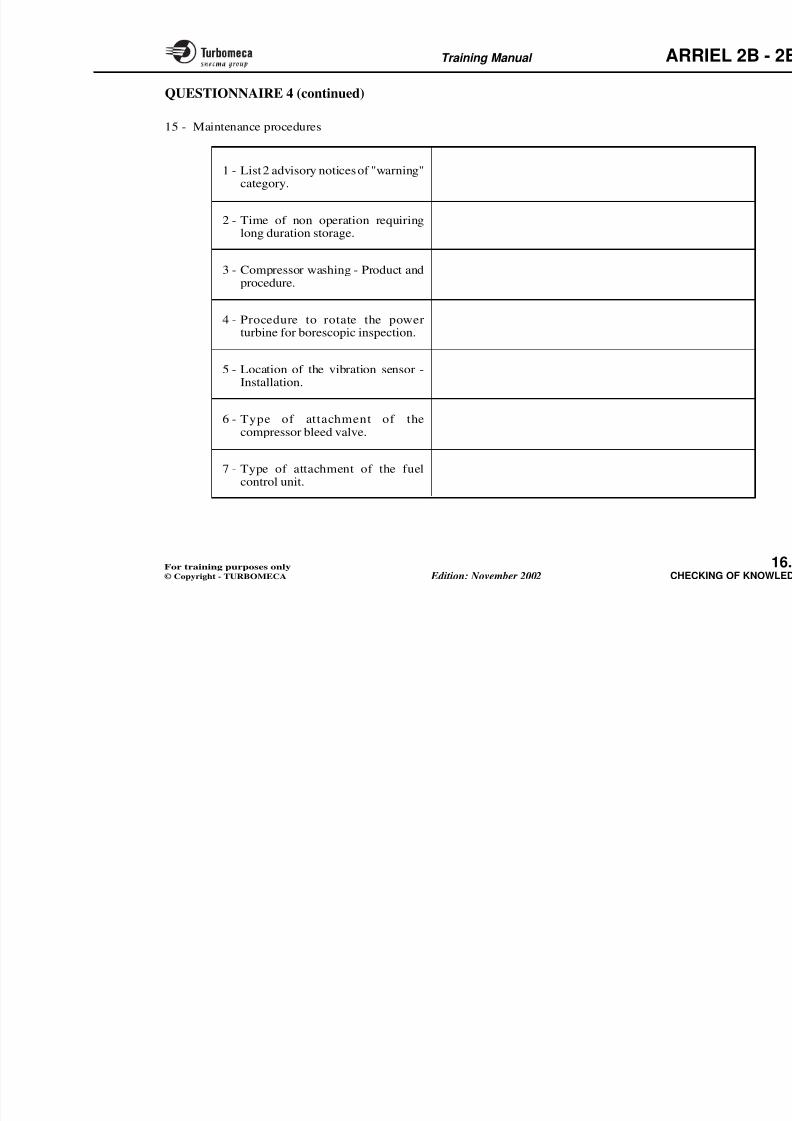
8/13/2019 Arriel_2B-2B1 11-02 En
http://slidepdf.com/reader/full/arriel2b-2b1-11-02-en 442/461
c) depends on conditions.14 - Ventilation of start injectors :
a) does not existb) is made with air from the compressorc) is made with atmospheric pressure air.
15 - The injection centrifugal wheel is drained :
a) permanentlyb) to enable the ventilation cyclec) during engine shut-down.
16 - The max speed of the gas generator is :
a) limited by the EECUb) limited by a mechanical stopc) not limited by the Fuel Control Unit.
19 - The fuel system pressurising va
a) is electrically controlledb) operates when overpressure oc) gives priority to the start inje
20 - Type of EECU :
a) hydraulicb) analogc) digital.
21 - The thermocouples are wired :a) in seriesb) in parallelc) on the turbine casing.
Training Manual ARR
QUESTIONNAIRE 3 (continued)
22 - The torque indicating system :
a) is hydraulicb) is not usedc) is of phase displacement type.
23 - Number of thermocouple probes :a) 8 x 2b) 4 x 2c) 3 x 2.
24 - Number of N2 signals :
a) 2
28 - HE ignition means :
a) Hot Electrodeb) High Energyc) High Emission.
29 - Borescopic inspection is used to
a) the external parts conditionb) the condition of internal p
accessible without removalc) the reduction gearbox conditi
30 The reliability of the engine is :
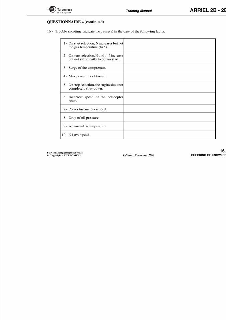
8/13/2019 Arriel_2B-2B1 11-02 En
http://slidepdf.com/reader/full/arriel2b-2b1-11-02-en 443/461
a) 2
b) 6c) 3.
25 - Number of N1 signals :
a) 3b) 2c) 6.
26 - The starter cut-off is made :a) automaticallyb) manuallyc) with air pressure.
27 - Starting is possible with one igniter :
a) yesb)
30 - The reliability of the engine is :
a) goodb) fairly goodc) extremely good.
3 - a
8 - a
1 3 - c
1 8 - c
2 3 - a
2 8 - b
4 - b
9 - a
1 4 - b
1 9 - c
2 4 - c
2 9 - b
5 - a
1 0 - b
1 5 - c
2 0 - c
2 5 - b
3 0 - a b c ?
Training Manual ARR
Max take-off power ........................
QUESTIONNAIRE 4
This questionnaire is a sort of drill which is also used to testand perfect the knowledge acquired.
1 - Complete this table (with values) :
2 - Name the reference stations and the right box:
G C T

8/13/2019 Arriel_2B-2B1 11-02 En
http://slidepdf.com/reader/full/arriel2b-2b1-11-02-en 444/461
Compression ratio .......................
Engine air flow .......................
N2 speed at 100 % ......................
N1 speed at 100 % ....................... 3 - ................................. 4,5 - ...
Q
CC
Training Manual ARR
QUESTIONNAIRE 4 (continued)
3 - Engine description - Complete the legend of thediagram :
1 2 3 4
8/13/2019 Arriel_2B-2B1 11-02 En
http://slidepdf.com/reader/full/arriel2b-2b1-11-02-en 445/461
1 - ................................................... 2 - ...................................................... 3 - ..................
4 - ................................................... 5 - ...................................................... 6 - .................
5
6
Training Manual ARR
QUESTIONNAIRE 4 (continued)
4 - Oil system - Complete the legend of the diagram :
1 2

8/13/2019 Arriel_2B-2B1 11-02 En
http://slidepdf.com/reader/full/arriel2b-2b1-11-02-en 446/461
1 - .......................... 2 - .......................... 3 - ........................... 4 - ........................ 5 -
Indication
5
4
Training Manual ARR
QUESTIONNAIRE 4 (continued)
5 - Complete the following table :
Injector ventilation
Aircraft services
P0 P2.6

8/13/2019 Arriel_2B-2B1 11-02 En
http://slidepdf.com/reader/full/arriel2b-2b1-11-02-en 447/461
Bleed valve control pressure
Injection wheel pressurisation
Axial compressor bearing pressurisation
Gas generator NGV cooling
Power turbine front bearing pressurisation
Gas generator front turbine disc cooling
Training Manual ARR
QUESTIONNAIRE 4 (continued)
6 - Complete the legend of the compressor field diagram :
A
COMPRESIONRATIO P3 / P0

8/13/2019 Arriel_2B-2B1 11-02 En
http://slidepdf.com/reader/full/arriel2b-2b1-11-02-en 448/461
B
C
AIR FLOW G
Training Manual ARR
QUESTIONNAIRE 4 (continued)
7 - Fuel system - List the components :
P3
4
2
3
9
6
1

8/13/2019 Arriel_2B-2B1 11-02 En
http://slidepdf.com/reader/full/arriel2b-2b1-11-02-en 449/461
1 - ................................................... 2 - ...................................................... 3 - ..................
4 - ................................................... 5 - ...................................................... 6 - .................
N1
N1
3
5
EngineAircraft

8/13/2019 Arriel_2B-2B1 11-02 En
http://slidepdf.com/reader/full/arriel2b-2b1-11-02-en 450/461
Training Manual ARR
QUESTIONNAIRE 4 (continued)
8 - Complete the following table :
Fuel pumps ........................................................
Pump pressure relief valve ................................
Engine stoppedEngine in st
fligh

8/13/2019 Arriel_2B-2B1 11-02 En
http://slidepdf.com/reader/full/arriel2b-2b1-11-02-en 451/461
Constant ∆P valve..............................................
Metering needle .................................................
Stop electro-valve ..............................................
Start electro-valve..............................................
Pressurising valve ..............................................
Injection wheel purge valve ...............................
Training Manual ARR
QUESTIONNAIRE 4 (continued)
10 - Control system - List the components :
N1 N2
NR
CH
CH*
1

8/13/2019 Arriel_2B-2B1 11-02 En
http://slidepdf.com/reader/full/arriel2b-2b1-11-02-en 452/461
1 - ................................................... 2 - ...................................................... 3 - ..................
6
3
N1*
N1*
N1*
N1*
4
CH*
2
5
N1 speed
N2 speed
N2 datum
Collective pitch
Training Manual ARR
QUESTIONNAIRE 4 (continued)
11 - Starting system - List the components :
A
M
Flight
Idle
Stop
ON
OFF
1
5
4
2

8/13/2019 Arriel_2B-2B1 11-02 En
http://slidepdf.com/reader/full/arriel2b-2b1-11-02-en 453/461
1 - .......................... 2 - .......................... 3 - ........................
6
3

8/13/2019 Arriel_2B-2B1 11-02 En
http://slidepdf.com/reader/full/arriel2b-2b1-11-02-en 454/461
Training Manual ARR
QUESTIONNAIRE 4 (continued)
14 - Definition of the following documents :
Maintenance manual
Spare parts catalogue
Tool catalogue

8/13/2019 Arriel_2B-2B1 11-02 En
http://slidepdf.com/reader/full/arriel2b-2b1-11-02-en 455/461
Service bulletin
Service letter
Engine log book
Flight manual
Training Manual ARR
QUESTIONNAIRE 4 (continued)
15 - Maintenance procedures
1 - List 2 advisory notices of "warning"category.
2 - Time of non operation requiringlong duration storage.

8/13/2019 Arriel_2B-2B1 11-02 En
http://slidepdf.com/reader/full/arriel2b-2b1-11-02-en 456/461
3 - Compressor washing - Product andprocedure.
4 - Procedure to rotate the powerturbine for borescopic inspection.
5 - Location of the vibration sensor -
Installation.
6 - Type of attachment of thecompressor bleed valve.
7 Type of attachment of the fuel
Training Manual ARR
QUESTIONNAIRE 4 (continued)
16 - Trouble shooting. Indicate the cause(s) in the case of the following faults.
1 - On start selection, N increases but not
the gas temperature (t4.5).
2 - On start selection, N and t4.5 increasebut not sufficiently to obtain start.
3 - Surge of the compressor.
4 - Max power not obtained

8/13/2019 Arriel_2B-2B1 11-02 En
http://slidepdf.com/reader/full/arriel2b-2b1-11-02-en 457/461
4 Max power not obtained.
5 - On stop selection, the engine does notcompletely shut-down.
6 - Incorrect speed of the helicopterrotor.
7 - Power turbine overspeed.
8 - Drop of oil pressure.
9 - Abnormal t4 temperature.
10 N1 d
EN D
but not the END of your t rainingwhich must be continued,
harmonizing knowledge and experience.
THANK YOU for your kind at tent ion.
of this manual and (maybe also) of the course

8/13/2019 Arriel_2B-2B1 11-02 En
http://slidepdf.com/reader/full/arriel2b-2b1-11-02-en 458/461
Au revo i rGood bye
Adiós
Auf Wiedersehen
Adeus
Arr ivederc i
Farve l
Tot z ie ns
Ad jö
Näkemi in
Ant io

8/13/2019 Arriel_2B-2B1 11-02 En
http://slidepdf.com/reader/full/arriel2b-2b1-11-02-en 459/461
REMARKS CONCERNING THE TRAINING AIDS REMARKS CONCERNING THE TRAI
REMARKS
Remarks (appreciations, criticisms, suggestions...) should be forwarded to :
TURBOMECACENTRE D'INSTRUCTION
40220 TARNOS - FRANCE

8/13/2019 Arriel_2B-2B1 11-02 En
http://slidepdf.com/reader/full/arriel2b-2b1-11-02-en 460/461
Name ....................................................................................................................................... .

8/13/2019 Arriel_2B-2B1 11-02 En
http://slidepdf.com/reader/full/arriel2b-2b1-11-02-en 461/461