Embed Size (px)
Citation preview
Auto-tuned Solution to Wide Area CoordinationIssues of Distance and Directional Time
Overcurrent Relay SettingsNathan Thomas
SynchroGridCollege Station, TX [email protected]
Luke HankinsSynchroGrid
College Station, TX [email protected]
Joe PerezSynchroGrid
College Station, TX [email protected]
Abstract—Relay coordination is an extremely difficult, yet vitalpart of a comprehensive protection strategy for modern powersystems. With the recent introduction of PRC-027-1 [14] andits requirement for coordination to be reevaluated at regularintervals, innovation to reduce the burden and resources requiredfor this activity is essential. Achieving coordination and ensuringthat relays operate in a predictable manner can be quite achallenging activity, especially in highly coupled power systemswith tight loops in the topology structure. In [3] we presentedan early prototype of a coordination autotuner framework anddemonstrated its use for the automatic generation of tuned pickupand time dial settings for direction time overcurrent relays on amix of synthetic and real world grids.
In this paper, we present improvements we have made to ourautotuner framework, moving us significantly closer to a generalpurpose coordination autotuner, capable of performing the mun-dane, iterative work required during coordination studies, withguidance and feedback from the protection engineer tasked withthe effort. We focus on several key areas including support foradditional coordination constraints (for implementing specificsof a utility’s standard), allowing more tunable parameters (e.g.,overcurrent curve) and alternative methods to calculate them,fault studies with contingencies, and incorporation of distanceelement responses. We show usage of each in the experiments,demonstrating how they allow us to better support common casesencountered in real world coordination studies. Together, thesenew capabilities address a large number of simplifying restric-tions in our previous work, making us increasingly confident thatautotuning-assisted coordination studies is a viable and importantadvancement quickly coming on the horizon in system protection.
Index Terms—Directional Time Overcurrent, MicroprocessorRelays, Time Dials, Wide Area Coordination
I. INTRODUCTION
Wide area coordination is one of the more difficult yetcritical aspects of system protection that ensures relays operatein a deterministic and appropriate manner in the presence oftheir neighboring relays. Just as with new settings creation,the coordination problem is made more complicated by thefact that there are many approaches and utility standardsto approach it, reasonably varying due to the nature of thegiven power system model, protection equipment, and otherfactors. Hence, any attempt to provide assistance to protectionengineers in the form of automation must be flexible enoughto adapt to a wide variety of applications.
Coordination is made even more difficult with modern mi-croprocessor relays that have multiple protective elements’ in-dividual responses combined to define the overall response ofthe relay. Hence, while directional time overcurrent elementsare generally considered much more difficult to coordinatethan distance elements, a proper coordination must integrateanalysis of both element types. This is necessary both to ensureproper coordination, but also to identify potential coordinationsolutions that otherwise might not be found with strictlyseparate overcurrent to overcurrent and distance to distancecoordination studies (see Section IV-C for further discussion).
This complex activity of relay coordination must be per-formed on an ongoing basis due to the dynamic and ever-changing nature of the electrical power grid. The addition(or removal) of generation sources, new transmission lines,as well as other equipment changes means a once-coordinatedsystem may no longer be. NERC recognized the necessity ofensuring proper coordination, addressing it in Requirement2 of PRC-027-1 [14], which is now going into effect. Withthe complexity and increasing frequency of the studies, theindustry is in need of innovation to streamline compliance,reduce the burden on engineering staff, and minimize theresources necessary for utilities of all sizes to achieve propercoordination. To that end, we are developing a coordinationauto-tuner that automatically creates candidate coordinatedsettings based on coordination criteria defined by the engineerand automated analysis of the short circuit model.
We previously [3] presented an early version of this autotun-ing framework in which we focused solely on directional timeovercurrent elements under very basic conditions (e.g., normalconditions) and only created settings for pickup and time dialsettings. We built upon previous work in the field [4], [6]–[9],beginning with a previous, non linear optimization formulationof the problem [6] based on short-circuit analysis enabledby [1] and then transforming the problem to a mixed integerlinear formulation as described in [9]. The formulation is thensimplified further based on adaptations made specifically forthe domain of system protection.
The goal of the work described in the paper is to improvethe capabilities of the prototype, identifying and implementing
features that may be potential roadblocks to the autotuner’s usein real world scenarios. It is based on feedback from clientsas well as obvious extensions (e.g., contingencies) necessaryto achieve our vision of an automated coordination assistantwhich dramatically reduces the engineering burden for thisactivity. We describe each improvement in turn and provideexperiments to demonstrate their usage.
The outline of this paper is as follows: In Section II, weprovide a brief overview of our autotuning framework and thendescribe the common experimental setup (Section III) that willbe used throughout the paper. The bulk of the paper lies inSection IV, where we discuss framework generalizations in-cluding expanded constraint support (IV-A), additional tunableparameters such as the overcurrent curve (IV-B), incorporationof distance element response (IV-C), and then contingencysupport (IV-D). In Section IV-E, we discuss the framework’shandling of cases when full coordination is not possible andits ability to selectively recommend targeted relaxations ofthe coordination criteria to inform judgement decisions thatthe engineer inevitably will need to make. Finally, we presentconclusions and discuss future work.
II. FRAMEWORK OVERVIEW
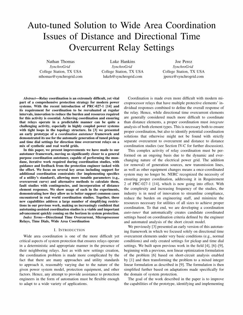
We briefly describe our autotuning framework, which isdepicted in Figure 1. At Project Inception, coordination criteriaare defined along with any additional tuneable parameterconstraints (such as those described in Section IV-A), andpassed to the Settings Selection Framework. Here, the co-ordination process begins by gathering topological informa-tion (coordination pairs, source/remote lines, etc), as wellas fault currents, settings reach, and more from the shortcircuit model. This is accomplished using the algorithms andinfrastructure presented in [1]. Next the Settings Generatortakes the coordination criteria and data derived from shortcircuit model as input. It then computes candidate settingswhich are then verified by the Coordination Verifier as in [2].These settings are then presented to the engineer for reviewand potentially further analysis leading to problem refinementand re-invocation of the framework.
In this paper, we make generalizations in the implemen-tation of the Settings Generator to support new features,and the Parameter / Constraint Definition interface (still textbased for now, but in the future graphical) is expanded toallow the engineer to drive these new features. Finally, theInput Collector now supports faults with contingencies as wellas retrieving the reach and operation time of distance relayelements.
III. EXPERIMENTAL SETUP
For power system modeling, fault simulations, and coor-dination checking, we used ASPEN OneLiner V14.8 withOlxAPI (ASPEN’s interface that our framework utilizes todirectly interact with the short circuit model). For topologicalanalysis and fault study generation, the core library of SARAv3.0.8 (based on [1], [2]) was employed. The autotun-ing framework itself is implemented in a modern C++20
codebase [22], compiled with Microsoft Visual Studio 2019v16.6.0. All studies were run on a laptop based on a quadcore Intel Core i7-8565U and containing 16GB of RAM.
All relays tuned are ground relays with single line to groundfaults being used in fault studies. Both the settings generatorand coordination verifier are directed to ensure coordinationfor a fault study regime including close-in, close-in end-opened, line-end, remote bus, and intermediate faults at every10% of the line. When included, contingencies considered arediscussed in Section IV-D. We require that no CTI violates thedefined threshold (CTI >= 0.33s). Unless otherwise noted,the auto-tuner is directed to prefer coordination solutions thatminimize the sum of each relay’s response to a close-in end-opened fault on its primary line.
IV. GENERALIZING THE AUTOTUNING FRAMEWORK
In this section, we present the various extensions that wehave made to our framework towards a goal of a generalpurpose tool for automated coordination. Though they vary inscope and implementation difficulty, each represents a criticalarea of improvement for the autotuner. We describe each inturn and provide experimental demonstration of how they areused in the framework.
A. Expanded Constraint Support
In [3], the primary constraint imposed on the SettingsGenerator was that of a minimum coordination time interval(CTI >= 0.33s). To ensure a realistic reach of the timeovercurrent element, we also required that it respond to allfaults on its primary line of protection, including a line-endfault. Besides lower and upper bounds on the tuned parametersof pickup and time dials, no other constraints were supportedin the first version of our framework.
Of course, such limitations on constraining the solutions inthe global coordination problem space are infeasible for realworld applications. Utilities’ protection standards regularlycontain additional requirements on relay settings to be coor-dinated. For example, the response time of time overcurrentelements to faults is often artificially increased by utilities toensure that it does not respond too quickly to some faults,often in anticipation of other elements (i.e. distance) of therelay responding to it first.
We are integrating a more customizable framework forconstraint specifications such as the one mentioned abovein our framework. Using a small symbolic language andbasic mathematical operations on terms such as fault typesand response times, basic constraints can be specified andtranslated into additional mixed integer inequality statementswhich are passed along with the CTI expressions and otherconstraints to the numerical solver. Both the essence andthe implementation of this language draw from a similartechnology we developed in [1], where it is used to allowa very flexible specification of transmission line relay settingsequations which are translated into both topology analysis andfault simulations in short circuit programs such as ASPENOneLiner and CAPE.
2
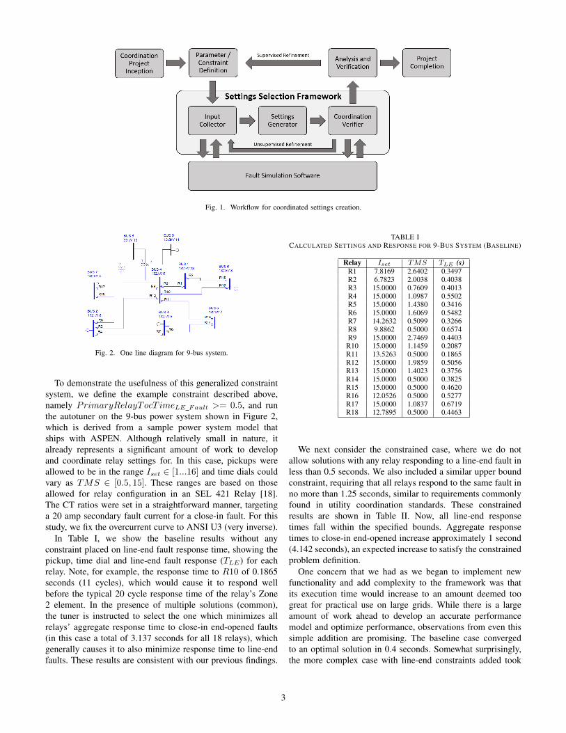
Fig. 1. Workflow for coordinated settings creation.
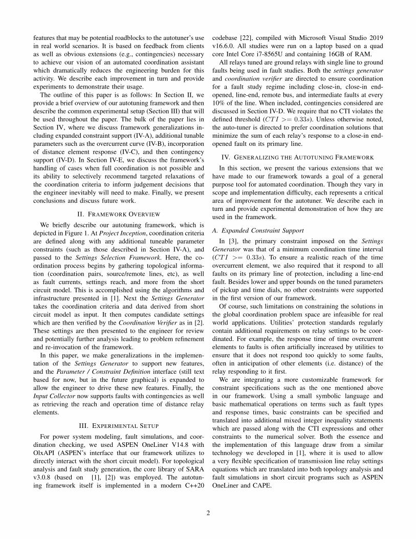
Fig. 2. One line diagram for 9-bus system.
To demonstrate the usefulness of this generalized constraintsystem, we define the example constraint described above,namely PrimaryRelayTocT imeLE Fault >= 0.5, and runthe autotuner on the 9-bus power system shown in Figure 2,which is derived from a sample power system model thatships with ASPEN. Although relatively small in nature, italready represents a significant amount of work to developand coordinate relay settings for. In this case, pickups wereallowed to be in the range Iset ∈ [1...16] and time dials couldvary as TMS ∈ [0.5, 15]. These ranges are based on thoseallowed for relay configuration in an SEL 421 Relay [18].The CT ratios were set in a straightforward manner, targetinga 20 amp secondary fault current for a close-in fault. For thisstudy, we fix the overcurrent curve to ANSI U3 (very inverse).
In Table I, we show the baseline results without anyconstraint placed on line-end fault response time, showing thepickup, time dial and line-end fault response (TLE) for eachrelay. Note, for example, the response time to R10 of 0.1865seconds (11 cycles), which would cause it to respond wellbefore the typical 20 cycle response time of the relay’s Zone2 element. In the presence of multiple solutions (common),the tuner is instructed to select the one which minimizes allrelays’ aggregate response time to close-in end-opened faults(in this case a total of 3.137 seconds for all 18 relays), whichgenerally causes it to also minimize response time to line-endfaults. These results are consistent with our previous findings.
TABLE ICALCULATED SETTINGS AND RESPONSE FOR 9-BUS SYSTEM (BASELINE)
Relay Iset TMS TLE (s)R1 7.8169 2.6402 0.3497R2 6.7823 2.0038 0.4038R3 15.0000 0.7609 0.4013R4 15.0000 1.0987 0.5502R5 15.0000 1.4380 0.3416R6 15.0000 1.6069 0.5482R7 14.2632 0.5099 0.3266R8 9.8862 0.5000 0.6574R9 15.0000 2.7469 0.4403R10 15.0000 1.1459 0.2087R11 13.5263 0.5000 0.1865R12 15.0000 1.9859 0.5056R13 15.0000 1.4023 0.3756R14 15.0000 0.5000 0.3825R15 15.0000 0.5000 0.4620R16 12.0526 0.5000 0.5277R17 15.0000 1.0837 0.6719R18 12.7895 0.5000 0.4463
We next consider the constrained case, where we do notallow solutions with any relay responding to a line-end fault inless than 0.5 seconds. We also included a similar upper boundconstraint, requiring that all relays respond to the same fault inno more than 1.25 seconds, similar to requirements commonlyfound in utility coordination standards. These constrainedresults are shown in Table II. Now, all line-end responsetimes fall within the specified bounds. Aggregate responsetimes to close-in end-opened increase approximately 1 second(4.142 seconds), an expected increase to satisfy the constrainedproblem definition.
One concern that we had as we began to implement newfunctionality and add complexity to the framework was thatits execution time would increase to an amount deemed toogreat for practical use on large grids. While there is a largeamount of work ahead to develop an accurate performancemodel and optimize performance, observations from even thissimple addition are promising. The baseline case convergedto an optimal solution in 0.4 seconds. Somewhat surprisingly,the more complex case with line-end constraints added took
3
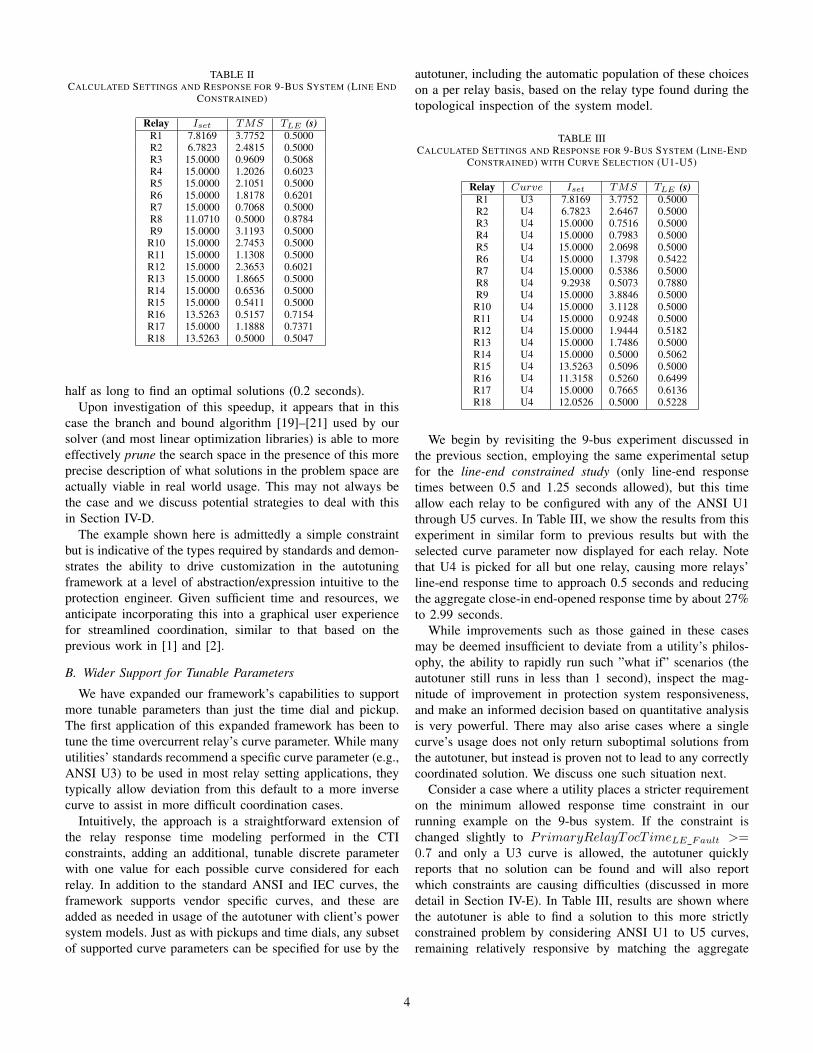
TABLE IICALCULATED SETTINGS AND RESPONSE FOR 9-BUS SYSTEM (LINE END
CONSTRAINED)
Relay Iset TMS TLE (s)R1 7.8169 3.7752 0.5000R2 6.7823 2.4815 0.5000R3 15.0000 0.9609 0.5068R4 15.0000 1.2026 0.6023R5 15.0000 2.1051 0.5000R6 15.0000 1.8178 0.6201R7 15.0000 0.7068 0.5000R8 11.0710 0.5000 0.8784R9 15.0000 3.1193 0.5000
R10 15.0000 2.7453 0.5000R11 15.0000 1.1308 0.5000R12 15.0000 2.3653 0.6021R13 15.0000 1.8665 0.5000R14 15.0000 0.6536 0.5000R15 15.0000 0.5411 0.5000R16 13.5263 0.5157 0.7154R17 15.0000 1.1888 0.7371R18 13.5263 0.5000 0.5047
half as long to find an optimal solutions (0.2 seconds).Upon investigation of this speedup, it appears that in this
case the branch and bound algorithm [19]–[21] used by oursolver (and most linear optimization libraries) is able to moreeffectively prune the search space in the presence of this moreprecise description of what solutions in the problem space areactually viable in real world usage. This may not always bethe case and we discuss potential strategies to deal with thisin Section IV-D.
The example shown here is admittedly a simple constraintbut is indicative of the types required by standards and demon-strates the ability to drive customization in the autotuningframework at a level of abstraction/expression intuitive to theprotection engineer. Given sufficient time and resources, weanticipate incorporating this into a graphical user experiencefor streamlined coordination, similar to that based on theprevious work in [1] and [2].
B. Wider Support for Tunable Parameters
We have expanded our framework’s capabilities to supportmore tunable parameters than just the time dial and pickup.The first application of this expanded framework has been totune the time overcurrent relay’s curve parameter. While manyutilities’ standards recommend a specific curve parameter (e.g.,ANSI U3) to be used in most relay setting applications, theytypically allow deviation from this default to a more inversecurve to assist in more difficult coordination cases.
Intuitively, the approach is a straightforward extension ofthe relay response time modeling performed in the CTIconstraints, adding an additional, tunable discrete parameterwith one value for each possible curve considered for eachrelay. In addition to the standard ANSI and IEC curves, theframework supports vendor specific curves, and these areadded as needed in usage of the autotuner with client’s powersystem models. Just as with pickups and time dials, any subsetof supported curve parameters can be specified for use by the
autotuner, including the automatic population of these choiceson a per relay basis, based on the relay type found during thetopological inspection of the system model.
TABLE IIICALCULATED SETTINGS AND RESPONSE FOR 9-BUS SYSTEM (LINE-END
CONSTRAINED) WITH CURVE SELECTION (U1-U5)
Relay Curve Iset TMS TLE (s)R1 U3 7.8169 3.7752 0.5000R2 U4 6.7823 2.6467 0.5000R3 U4 15.0000 0.7516 0.5000R4 U4 15.0000 0.7983 0.5000R5 U4 15.0000 2.0698 0.5000R6 U4 15.0000 1.3798 0.5422R7 U4 15.0000 0.5386 0.5000R8 U4 9.2938 0.5073 0.7880R9 U4 15.0000 3.8846 0.5000
R10 U4 15.0000 3.1128 0.5000R11 U4 15.0000 0.9248 0.5000R12 U4 15.0000 1.9444 0.5182R13 U4 15.0000 1.7486 0.5000R14 U4 15.0000 0.5000 0.5062R15 U4 13.5263 0.5096 0.5000R16 U4 11.3158 0.5260 0.6499R17 U4 15.0000 0.7665 0.6136R18 U4 12.0526 0.5000 0.5228
We begin by revisiting the 9-bus experiment discussed inthe previous section, employing the same experimental setupfor the line-end constrained study (only line-end responsetimes between 0.5 and 1.25 seconds allowed), but this timeallow each relay to be configured with any of the ANSI U1through U5 curves. In Table III, we show the results from thisexperiment in similar form to previous results but with theselected curve parameter now displayed for each relay. Notethat U4 is picked for all but one relay, causing more relays’line-end response time to approach 0.5 seconds and reducingthe aggregate close-in end-opened response time by about 27%to 2.99 seconds.
While improvements such as those gained in these casesmay be deemed insufficient to deviate from a utility’s philos-ophy, the ability to rapidly run such ”what if” scenarios (theautotuner still runs in less than 1 second), inspect the mag-nitude of improvement in protection system responsiveness,and make an informed decision based on quantitative analysisis very powerful. There may also arise cases where a singlecurve’s usage does not only return suboptimal solutions fromthe autotuner, but instead is proven not to lead to any correctlycoordinated solution. We discuss one such situation next.
Consider a case where a utility places a stricter requirementon the minimum allowed response time constraint in ourrunning example on the 9-bus system. If the constraint ischanged slightly to PrimaryRelayTocT imeLE Fault >=0.7 and only a U3 curve is allowed, the autotuner quicklyreports that no solution can be found and will also reportwhich constraints are causing difficulties (discussed in moredetail in Section IV-E). In Table III, results are shown wherethe autotuner is able to find a solution to this more strictlyconstrained problem by considering ANSI U1 to U5 curves,remaining relatively responsive by matching the aggregate
4
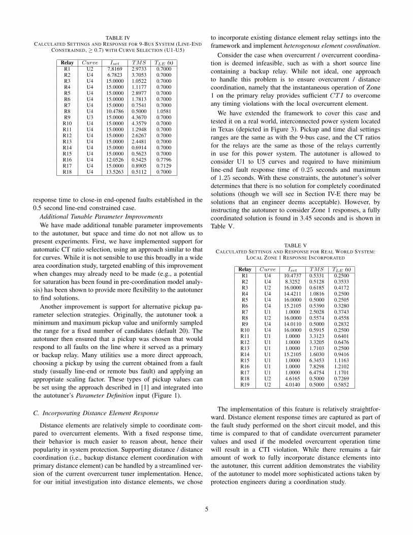
TABLE IVCALCULATED SETTINGS AND RESPONSE FOR 9-BUS SYSTEM (LINE-END
CONSTRAINED, ≥ 0.7) WITH CURVE SELECTION (U1-U5)
Relay Curve Iset TMS TLE (s)R1 U2 7.8169 2.9733 0.7000R2 U4 6.7823 3.7053 0.7000R3 U4 15.0000 1.0522 0.7000R4 U4 15.0000 1.1177 0.7000R5 U4 15.0000 2.8977 0.7000R6 U4 15.0000 1.7813 0.7000R7 U4 15.0000 0.7541 0.7000R8 U4 10.4786 0.5000 1.0581R9 U3 15.0000 4.3670 0.7000
R10 U4 15.0000 4.3579 0.7000R11 U4 15.0000 1.2948 0.7000R12 U4 15.0000 2.6267 0.7000R13 U4 15.0000 2.4481 0.7000R14 U4 15.0000 0.6914 0.7000R15 U4 15.0000 0.5623 0.7000R16 U4 12.0526 0.5425 0.7796R17 U4 15.0000 0.8905 0.7129R18 U4 13.5263 0.5112 0.7000
response time to close-in end-opened faults established in the0.5 second line-end constrained case.
Additional Tunable Parameter ImprovementsWe have made additional tunable parameter improvements
to the autotuner, but space and time do not not allow us topresent experiments. First, we have implemented support forautomatic CT ratio selection, using an approach similar to thatfor curves. While it is not sensible to use this broadly in a widearea coordination study, targeted enabling of this improvementwhen changes may already need to be made (e.g., a potentialfor saturation has been found in pre-coordination model analy-sis) has been shown to provide more flexibility to the autotunerto find solutions.
Another improvement is support for alternative pickup pa-rameter selection strategies. Originally, the autotuner took aminimum and maximum pickup value and uniformly sampledthe range for a fixed number of candidates (default 20). Theautotuner then ensured that a pickup was chosen that wouldrespond to all faults on the line where it served as a primaryor backup relay. Many utilities use a more direct approach,choosing a pickup by using the current obtained from a faultstudy (usually line-end or remote bus fault) and applying anappropriate scaling factor. These types of pickup values canbe set using the approach described in [1] and integrated intothe autotuner’s Parameter Definition input (Figure 1).
C. Incorporating Distance Element Response
Distance elements are relatively simple to coordinate com-pared to overcurrent elements. With a fixed response time,their behavior is much easier to reason about, hence theirpopularity in system protection. Supporting distance / distancecoordination (i.e., backup distance element coordination withprimary distance element) can be handled by a streamlined ver-sion of the current overcurrent tuner implementation. Hence,for our initial investigation into distance elements, we chose
to incorporate existing distance element relay settings into theframework and implement heterogenous element coordination.
Consider the case when overcurrent / overcurrent coordina-tion is deemed infeasible, such as with a short source linecontaining a backup relay. While not ideal, one approachto handle this problem is to ensure overcurrent / distancecoordination, namely that the instantaneous operation of Zone1 on the primary relay provides sufficient CTI to overcomeany timing violations with the local overcurrent element.
We have extended the framework to cover this case andtested it on a real world, interconnected power system locatedin Texas (depicted in Figure 3). Pickup and time dial settingsranges are the same as with the 9-bus case, and the CT ratiosfor the relays are the same as those of the relays currentlyin use for this power system. The autotuner is allowed toconsider U1 to U5 curves and required to have minimiumline-end fault response time of 0.25 seconds and maximumof 1.25 seconds. With these constraints, the autotuner’s solverdetermines that there is no solution for completely coordinatedsolutions (though we will see in Section IV-E there may besolutions that an engineer deems acceptable). However, byinstructing the autotuner to consider Zone 1 responses, a fullycoordinated solution is found in 3.45 seconds and is shown inTable V.
TABLE VCALCULATED SETTINGS AND RESPONSE FOR REAL WORLD SYSTEM:
LOCAL ZONE 1 RESPONSE INCORPORATED
Relay Curve Iset TMS TLE (s)R1 U4 10.4737 0.5331 0.2500R2 U4 8.3252 0.5128 0.3533R3 U2 16.0000 0.6185 0.4172R4 U4 14.4211 1.0816 0.2500R5 U4 16.0000 0.5000 0.2505R6 U4 15.2105 0.5390 0.3280R7 U1 1.0000 2.5028 0.3743R8 U2 16.0000 0.5574 0.4558R9 U4 14.0110 0.5000 0.2832
R10 U4 16.0000 0.5915 0.2500R11 U1 1.0000 3.3123 0.6401R12 U1 1.0000 3.3205 0.6476R13 U1 1.0000 1.7103 0.2500R14 U1 15.2105 1.6030 0.9416R15 U1 1.0000 6.3453 1.1163R16 U1 1.0000 7.8298 1.2102R17 U1 1.0000 6.4754 1.1701R18 U2 4.6165 0.5000 0.7269R19 U2 4.0140 0.5000 0.5852
The implementation of this feature is relatively straightfor-ward. Distance element response times are captured as part ofthe fault study performed on the short circuit model, and thistime is compared to that of candidate overcurrent parametervalues and used if the modeled overcurrent operation timewill result in a CTI violation. While there remains a fairamount of work to fully incorporate distance elements intothe autotuner, this current addition demonstrates the viabilityof the autotuner to model more sophisticated actions taken byprotection engineers during a coordination study.
5
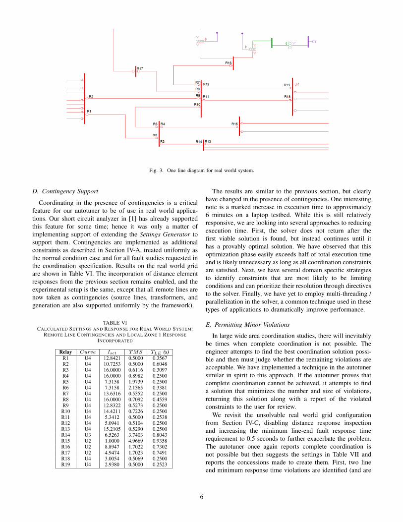
Fig. 3. One line diagram for real world system.
D. Contingency Support
Coordinating in the presence of contingencies is a criticalfeature for our autotuner to be of use in real world applica-tions. Our short circuit analyzer in [1] has already supportedthis feature for some time; hence it was only a matter ofimplementing support of extending the Settings Generator tosupport them. Contingencies are implemented as additionalconstraints as described in Section IV-A, treated uniformly asthe normal condition case and for all fault studies requested inthe coordination specification. Results on the real world gridare shown in Table VI. The incorporation of distance elementresponses from the previous section remains enabled, and theexperimental setup is the same, except that all remote lines arenow taken as contingencies (source lines, transformers, andgeneration are also supported uniformly by the framework).
TABLE VICALCULATED SETTINGS AND RESPONSE FOR REAL WORLD SYSTEM:
REMOTE LINE CONTINGENCIES AND LOCAL ZONE 1 RESPONSEINCORPORATED
Relay Curve Iset TMS TLE (s)R1 U4 12.8421 0.5000 0.3567R2 U4 10.7253 0.5000 0.6048R3 U4 16.0000 0.6116 0.3097R4 U4 16.0000 0.8982 0.2500R5 U4 7.3158 1.9739 0.2500R6 U4 7.3158 2.1365 0.3381R7 U4 13.6316 0.5352 0.2500R8 U4 16.0000 0.7092 0.4559R9 U4 12.8322 0.5273 0.2500
R10 U4 14.4211 0.7226 0.2500R11 U4 5.3412 0.5000 0.2538R12 U4 5.0941 0.5104 0.2500R13 U4 15.2105 0.5290 0.2500R14 U3 6.5263 3.7403 0.8043R15 U2 1.0000 4.9669 0.9358R16 U2 8.8947 1.7022 0.7302R17 U2 4.9474 1.7023 0.7491R18 U4 3.0054 0.5069 0.2500R19 U4 2.9380 0.5000 0.2523
The results are similar to the previous section, but clearlyhave changed in the presence of contingencies. One interestingnote is a marked increase in execution time to approximately6 minutes on a laptop testbed. While this is still relativelyresponsive, we are looking into several approaches to reducingexecution time. First, the solver does not return after thefirst viable solution is found, but instead continues until ithas a provably optimal solution. We have observed that thisoptimization phase easily exceeds half of total execution timeand is likely unnecessary as long as all coordination constraintsare satisfied. Next, we have several domain specific strategiesto identify constraints that are most likely to be limitingconditions and can prioritize their resolution through directivesto the solver. Finally, we have yet to employ multi-threading /parallelization in the solver, a common technique used in thesetypes of applications to dramatically improve performance.
E. Permitting Minor Violations
In large wide area coordination studies, there will inevitablybe times when complete coordination is not possible. Theengineer attempts to find the best coordination solution possi-ble and then must judge whether the remaining violations areacceptable. We have implemented a technique in the autotunersimilar in spirit to this approach. If the autotuner proves thatcomplete coordination cannot be achieved, it attempts to finda solution that minimizes the number and size of violations,returning this solution along with a report of the violatedconstraints to the user for review.
We revisit the unsolvable real world grid configurationfrom Section IV-C, disabling distance response inspectionand increasing the minimum line-end fault response timerequirement to 0.5 seconds to further exacerbate the problem.The autotuner once again reports complete coordination isnot possible but then suggests the settings in Table VII andreports the concessions made to create them. First, two lineend minimum response time violations are identified (and are
6
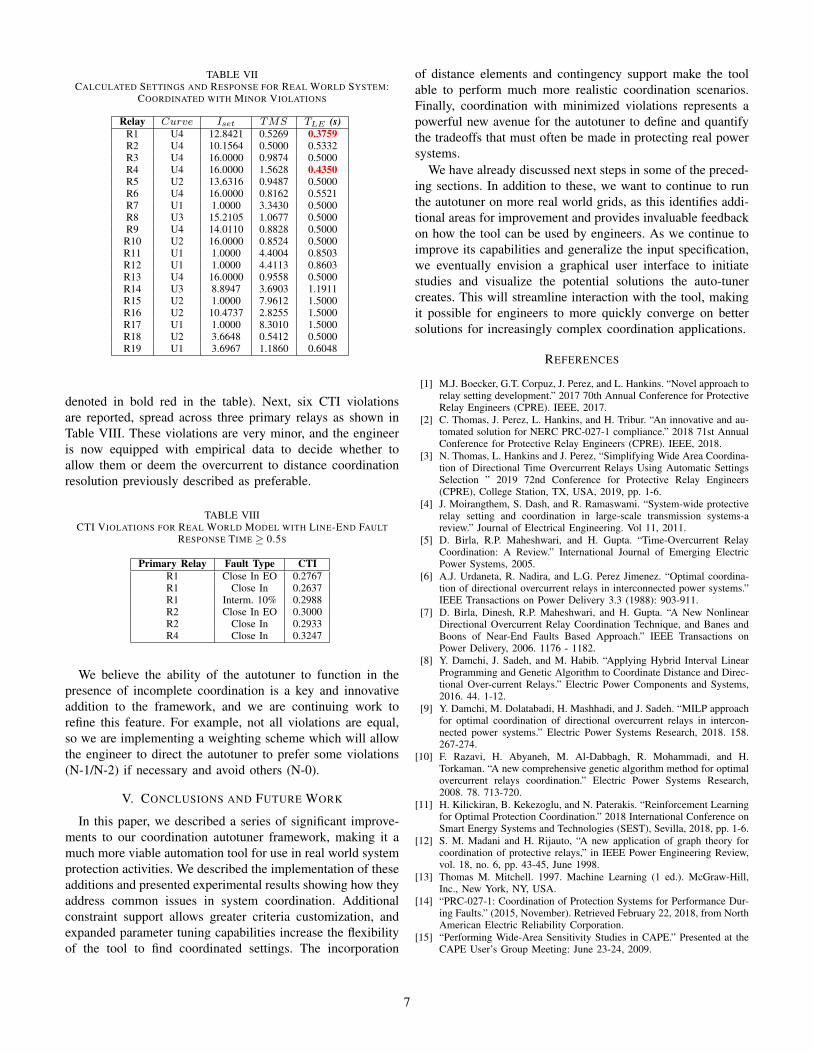
TABLE VIICALCULATED SETTINGS AND RESPONSE FOR REAL WORLD SYSTEM:
COORDINATED WITH MINOR VIOLATIONS
Relay Curve Iset TMS TLE (s)R1 U4 12.8421 0.5269 0.3759R2 U4 10.1564 0.5000 0.5332R3 U4 16.0000 0.9874 0.5000R4 U4 16.0000 1.5628 0.4350R5 U2 13.6316 0.9487 0.5000R6 U4 16.0000 0.8162 0.5521R7 U1 1.0000 3.3430 0.5000R8 U3 15.2105 1.0677 0.5000R9 U4 14.0110 0.8828 0.5000
R10 U2 16.0000 0.8524 0.5000R11 U1 1.0000 4.4004 0.8503R12 U1 1.0000 4.4113 0.8603R13 U4 16.0000 0.9558 0.5000R14 U3 8.8947 3.6903 1.1911R15 U2 1.0000 7.9612 1.5000R16 U2 10.4737 2.8255 1.5000R17 U1 1.0000 8.3010 1.5000R18 U2 3.6648 0.5412 0.5000R19 U1 3.6967 1.1860 0.6048
denoted in bold red in the table). Next, six CTI violationsare reported, spread across three primary relays as shown inTable VIII. These violations are very minor, and the engineeris now equipped with empirical data to decide whether toallow them or deem the overcurrent to distance coordinationresolution previously described as preferable.
TABLE VIIICTI VIOLATIONS FOR REAL WORLD MODEL WITH LINE-END FAULT
RESPONSE TIME ≥ 0.5S
Primary Relay Fault Type CTIR1 Close In EO 0.2767R1 Close In 0.2637R1 Interm. 10% 0.2988R2 Close In EO 0.3000R2 Close In 0.2933R4 Close In 0.3247
We believe the ability of the autotuner to function in thepresence of incomplete coordination is a key and innovativeaddition to the framework, and we are continuing work torefine this feature. For example, not all violations are equal,so we are implementing a weighting scheme which will allowthe engineer to direct the autotuner to prefer some violations(N-1/N-2) if necessary and avoid others (N-0).
V. CONCLUSIONS AND FUTURE WORK
In this paper, we described a series of significant improve-ments to our coordination autotuner framework, making it amuch more viable automation tool for use in real world systemprotection activities. We described the implementation of theseadditions and presented experimental results showing how theyaddress common issues in system coordination. Additionalconstraint support allows greater criteria customization, andexpanded parameter tuning capabilities increase the flexibilityof the tool to find coordinated settings. The incorporation
of distance elements and contingency support make the toolable to perform much more realistic coordination scenarios.Finally, coordination with minimized violations represents apowerful new avenue for the autotuner to define and quantifythe tradeoffs that must often be made in protecting real powersystems.
We have already discussed next steps in some of the preced-ing sections. In addition to these, we want to continue to runthe autotuner on more real world grids, as this identifies addi-tional areas for improvement and provides invaluable feedbackon how the tool can be used by engineers. As we continue toimprove its capabilities and generalize the input specification,we eventually envision a graphical user interface to initiatestudies and visualize the potential solutions the auto-tunercreates. This will streamline interaction with the tool, makingit possible for engineers to more quickly converge on bettersolutions for increasingly complex coordination applications.
REFERENCES
[1] M.J. Boecker, G.T. Corpuz, J. Perez, and L. Hankins. “Novel approach torelay setting development.” 2017 70th Annual Conference for ProtectiveRelay Engineers (CPRE). IEEE, 2017.
[2] C. Thomas, J. Perez, L. Hankins, and H. Tribur. “An innovative and au-tomated solution for NERC PRC-027-1 compliance.” 2018 71st AnnualConference for Protective Relay Engineers (CPRE). IEEE, 2018.
[3] N. Thomas, L. Hankins and J. Perez, “Simplifying Wide Area Coordina-tion of Directional Time Overcurrent Relays Using Automatic SettingsSelection ” 2019 72nd Conference for Protective Relay Engineers(CPRE), College Station, TX, USA, 2019, pp. 1-6.
[4] J. Moirangthem, S. Dash, and R. Ramaswami. “System-wide protectiverelay setting and coordination in large-scale transmission systems-areview.” Journal of Electrical Engineering. Vol 11, 2011.
[5] D. Birla, R.P. Maheshwari, and H. Gupta. “Time-Overcurrent RelayCoordination: A Review.” International Journal of Emerging ElectricPower Systems, 2005.
[6] A.J. Urdaneta, R. Nadira, and L.G. Perez Jimenez. “Optimal coordina-tion of directional overcurrent relays in interconnected power systems.”IEEE Transactions on Power Delivery 3.3 (1988): 903-911.
[7] D. Birla, Dinesh, R.P. Maheshwari, and H. Gupta. “A New NonlinearDirectional Overcurrent Relay Coordination Technique, and Banes andBoons of Near-End Faults Based Approach.” IEEE Transactions onPower Delivery, 2006. 1176 - 1182.
[8] Y. Damchi, J. Sadeh, and M. Habib. “Applying Hybrid Interval LinearProgramming and Genetic Algorithm to Coordinate Distance and Direc-tional Over-current Relays.” Electric Power Components and Systems,2016. 44. 1-12.
[9] Y. Damchi, M. Dolatabadi, H. Mashhadi, and J. Sadeh. “MILP approachfor optimal coordination of directional overcurrent relays in intercon-nected power systems.” Electric Power Systems Research, 2018. 158.267-274.
[10] F. Razavi, H. Abyaneh, M. Al-Dabbagh, R. Mohammadi, and H.Torkaman. “A new comprehensive genetic algorithm method for optimalovercurrent relays coordination.” Electric Power Systems Research,2008. 78. 713-720.
[11] H. Kilickiran, B. Kekezoglu, and N. Paterakis. “Reinforcement Learningfor Optimal Protection Coordination.” 2018 International Conference onSmart Energy Systems and Technologies (SEST), Sevilla, 2018, pp. 1-6.
[12] S. M. Madani and H. Rijauto, “A new application of graph theory forcoordination of protective relays,” in IEEE Power Engineering Review,vol. 18, no. 6, pp. 43-45, June 1998.
[13] Thomas M. Mitchell. 1997. Machine Learning (1 ed.). McGraw-Hill,Inc., New York, NY, USA.
[14] “PRC-027-1: Coordination of Protection Systems for Performance Dur-ing Faults.” (2015, November). Retrieved February 22, 2018, from NorthAmerican Electric Reliability Corporation.
[15] “Performing Wide-Area Sensitivity Studies in CAPE.” Presented at theCAPE User’s Group Meeting: June 23-24, 2009.
7
[16] “System Wide Area Coordination Analysis.” Presented at the CAPEUser’s Group Meeting: June 23-27, 2014.
[17] ASPEN Oneliner. https://www.aspeninc.com/web/software/oneliner.[18] SEL-5030 acSELerator QuickSet Software.
https://selinc.com/products/5030/[19] A. H. Land and A. G. Doig. “An Automatic Method of Solving Discrete
Programming Problems” Econometrica, vol. 28, no. 3, 1960, pp. 497-520.
[20] J. Little, K. Murty, D. Sweeney, and C. Karel. 1963. “An Algorithm forthe Traveling Salesman Problem.” Oper. Res. 11, 6 (December 1963),972-989.
[21] D. Morrison, S. Jacobson, J. Sauppe, and E. Sewell. 2016. “Branch-and-bound algorithms.” Discret. Optim. 19, C (February 2016), 79-102.
[22] ISO/IEC. (2020). “ISO International Standard ISO/IEC 14882:2020(E),Programming Language C++.” [Working draft]. Geneva, Switzerland:International Organization for Standardization (ISO). Retrieved fromhttps://isocpp.org/std/the-standard
VI. AUTHOR BIOGRAPHIES
Nathan Thomas earned B.S. and Ph.D. degrees from TexasA&M University in 1999 and 2012, respectively, both inComputer Science. He has an extensive background in highperformance computing for large-scale engineering and scien-tific applications. He is also interested in machine learning andhow it can be used to maximize system performance. Nathancofounded and leads development at SynchroSoft, the softwareand automation division of SynchroGrid.
Luke Hankins graduated from Texas A&M University witha B.S. degree in Electrical Engineering in 2015. He is aregistered professional engineer in the state of Texas and worksfor SynchroGrid in the area of relay setting automation. Hewrites software applications in various programing languages,focusing on simplifying relay setting development. Addition-ally, Luke oversees relay settings verification and has assistedwith mis-operation analysis.
Joe Perez received his B.S. degree in Electrical Engineeringfrom Texas A&M University in 2003. Joe is the author of manyrelay application notes and has presented technical papers atWPRC, Texas A&M, and Georgia Tech Relay Conferences.Joe is the owner of SynchroGrid, a registered professionalengineer in the state of Texas and a member of PSRC, IEEE,and PES.
8