Embed Size (px)
Citation preview
GROWTH OF NANOTUBES: THE COMBINED TEM AND PHASE-DIAGRAMAPPROACH
A. LOISEAU I, F. WILLAIME2
1 Laboratoire d'Etude des Microstructures, UMR n° 104 ONERA-CNRS,Onera, B.P. 72, 92322 Chiitillon Cedex, France. e-mail:Loiseau@onerafr2 Section de Recherches de Metallurgie Physique, CEA/Saclay, F-91191Gif-sur- Yvette, France. e-mail:@fwillaime@ceafr
1. Introduction
The main current challenges in the synthesis of nanotubes are on the one hand theoptimization of the production of existing structures - in particular ropes of single wallcarbon nanotubes (SWNT) (1] - and on the other hand the exploration of novelstructures, such as multi-element nanotubes, including carbon nanotubes filled withforeign materials. Controlling their fabrication requires first to be able to determinetheir structural and chemical characteristics in a quantitative way. Transmissionelectron microscopy (TEM) provides a unique way for studying the morphologies, thestructure and the chemistry of nanotubular materials and has therefore highlycontributed to the development of the research on this new kind of structures.Understanding the growth mechanisms is expected to help controlling and optimizingthe production of nanotubes with definite geometry and chemistry. No coherent schemeon the growth mechanism has indeed clearly emerged yet, in particular for SWNTropes, in spite of intensive experimental [2 - 6] and theoretical researches [7]. In situstudies have just started for different reaction chambers. They are very promising fordetermining characteristics of the temperature gradient and the time evolution of thematter aggregation after the initial vaporization of the different chemical species [8 10], but for the moment one has to rely on studies on the soot after the synthesis. Manyuseful information about the formation of nanotubes can again be deduced from TEMobservations.
In this paper we shall illustrate with two different examples how TEM can be used tostudy both the structure and the growth of nanotubular structures. These examplesconcern composite nanotubes: carbon multiwalled nanotubes filled with differentmetals on the one hand and BN - C nanotubes on the other hand. We shall show how
133
L.P. Biro et al. (eds.), Carbon Filaments and Nanotubes: Common Origins, Differing Applications, 133-148.© 2001 Kluwer Academic Publishers.

134
the knowledge on these multi element nanotubes provides clues for identifying thegeneral physical processes which govern the growth of nanotubes. The TEM resultsobtained previously on these two types of tubes are summarized, and a metallurgicalapproach based on phase diagrams is proposed to deduce simple schemes accountingfor the observed structures. Finally, the phase diagram arguments being very successfulin the two cases considered here, a perspective is drawn to apply the same approach tothe formation of SWNT in order to explain the role of catalyst.
2. Experimental
Various methods have been developed to synthesize carbon nanotubes (for a review seee.g. [10 - 13]) and among them the arc discharge method which consists, in its originalform, in establishing an electric arc between two graphite electrodes in a Heatmosphere. This method was adapted as follows to produce the multi-elementnanotubes studied here.The filled nanotubes [14] were obtained by drilling the graphite rod for the anode andfilling it with a mixture of graphite and chosen element powders. Not less than 41elements have been tested. We emphasize that in this type of method the tubes areproduced and filled simultaneously, whereas other routes are based on the initial idea ofusing pre-existing tubes, opening them by oxidation and filling them by physical orchemical techniques (for a review see e.g. [15 - 17]).The B-C-N nanotubes studied here were obtained by arcing a graphite cathode with anHfB2 anode in a nitrogen atmosphere [18], following the idea used to producesuccessfully pure BN tubes from two HfB2 electrodes [19]. In this configuration thethree constituents (B, C and N) have different sources and this was the key forproducing composite nanotubes with high Band N contents. When using otherconfigurations involving doped carbon electrodes only low doping by Band N areobtained [20].
Both the structure and the chemical composition of the nanotubes were investigated indetail by Transmission Electron Microscopy (TEM): selected area electron diffraction(SAED), high resolution imaging (HRTEM) and Electron Energy Loss Spectroscopy(EELS). HRTEM and standard EELS characterizations were performed using a JEOL4000FX working at 400 kV, equipped with a Oatan 666 parallel collection electronenergy-loss spectrometer. The high spatial resolution EELS results which are recalledin this paper were obtained using a dedicated scanning transmission electronmicroscope (STEM) VO HB501, working at 100 kV, equipped with a field-emissionsource and a parallel collection electron energy-loss spectrometer [21].
135
3. Filled nanotubes
3.1 STRUCTURAL ANALYSIS
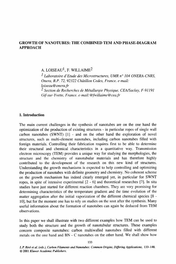
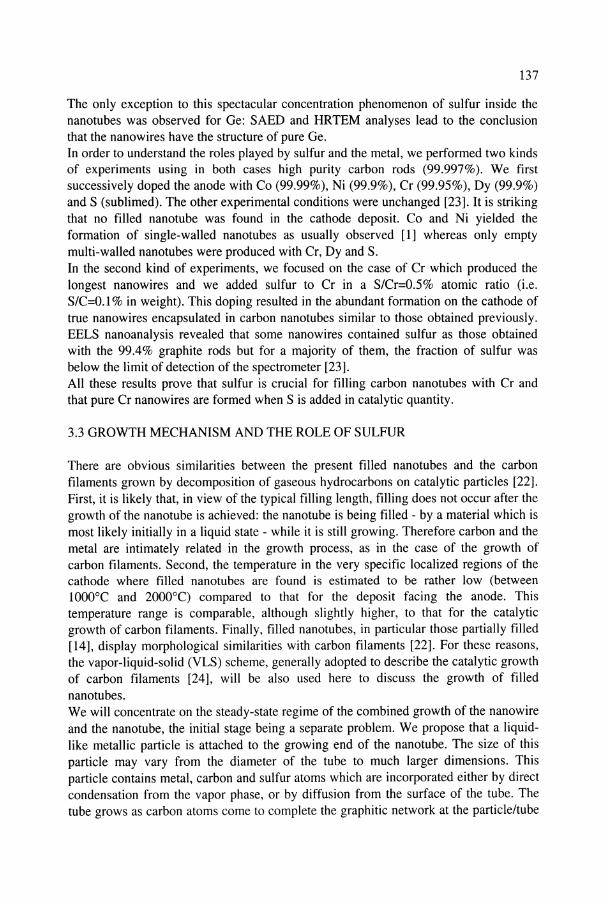
Long continuous fillings were obtained for twelve elements belonging to differentgroups [14]: transition metals (Cr, Ni, Re, Au), rare earth metals (Sm, Gd, Dy, Yb) andcovalent elements (S, Ge, Se, Sb). Partial fillings were also obtained with elements likeMn, Co, Fe, Pd, Nb, Hf, Os, B, Te, Bi. In these cases, the filling is discontinuous andconsists of a sequence of particles - not exceeding a few hundred nanometers - locatedat different places along the tube. These nanotubes are hollow at one end and oftencapped by a particle at the other end. These partially filled nanotubes closely resemblevapor grown carbon fibres [22]. The structural characteristics of both kinds ofnanotubes, i.e. the number of graphitic layers, the degree of graphitization, thecrystallinity of the filling material, depend on the chosen element as described in [23].The variety of the microstructures is shown in detail in [15].The encapsulated crystals were initially thought to be carbides since in most cases thecorresponding SAED patterns were not consistent with the structure of the pureelements [23]. The chemical composition of the filling material has been theninvestigated in a rather systematic way using high spatial resolution. Surprisingly, thesenanoanalyses revealed that the nanowires obtained with metals are not carbon-rich asinitially assumed but contain sulfur. The source of sulfur was found to be the graphiteelectrodes (99.4 %): a refined analysis of this graphite revealed that the majorimpurities are Fe (0.3 %) and S (:::; 0.25%). The analysis of different cases is presentedin detail in [23] and shows that important amounts of sulfur were found in numerousfilling materials along with the inserted element.In some cases as Cr-based nanowires, nanowires are very long single crystals and amajority of them was found to contain sulfur in a ratio close to I: I, excluding any otherelement. Figure I presents an example of concentration profiles deduced from a linespectrum across a filled nanotube. The C profile is characteristic of a hollow carbonnanotube (i.e. it starts abruptly, reaches a maximum at the inner radius and decreases tothe centre) and is perfectly anticorrelated to both the Sand Cr profiles. The analysis ofthese profiles suggests that the tubular layers wrapping the nanowire are poor-to-free ofsulfur and of metal and that the filling material does not contain a significant amount ofcarbon [23]. Furthermore, Sand Cr profiles are very correlated, suggesting that thefilling is an homogeneous chromium sulfide. The structure of these sulfides has beenidentified from SAED and HRTEM analyses to be the trigonal compounds CrSS6 orCr2S3'
136
-""~".2~~8u
J'-dli.... .s!L...............~.......]~..._ ....-15 -10 -5 0 5 10 15
Probe position (nm)
Figure 1 : Analysis of a filled nanotube obtained with a 99.4% graphite anode doped with Cr. Left:Concentration profiles of C. Cr and S deduced from the EELS line-spectra. Right: HRTEM image of thecorresponding nanowire.
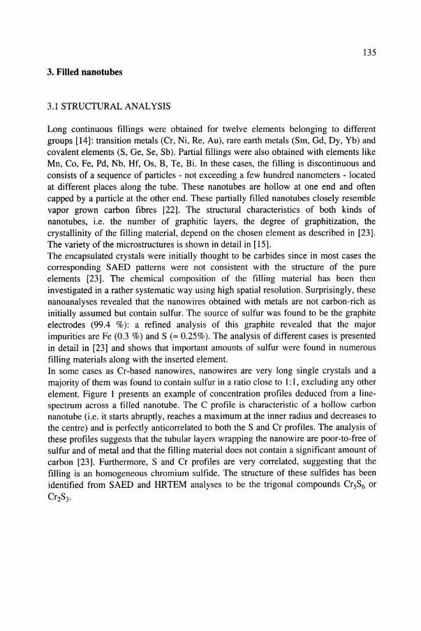
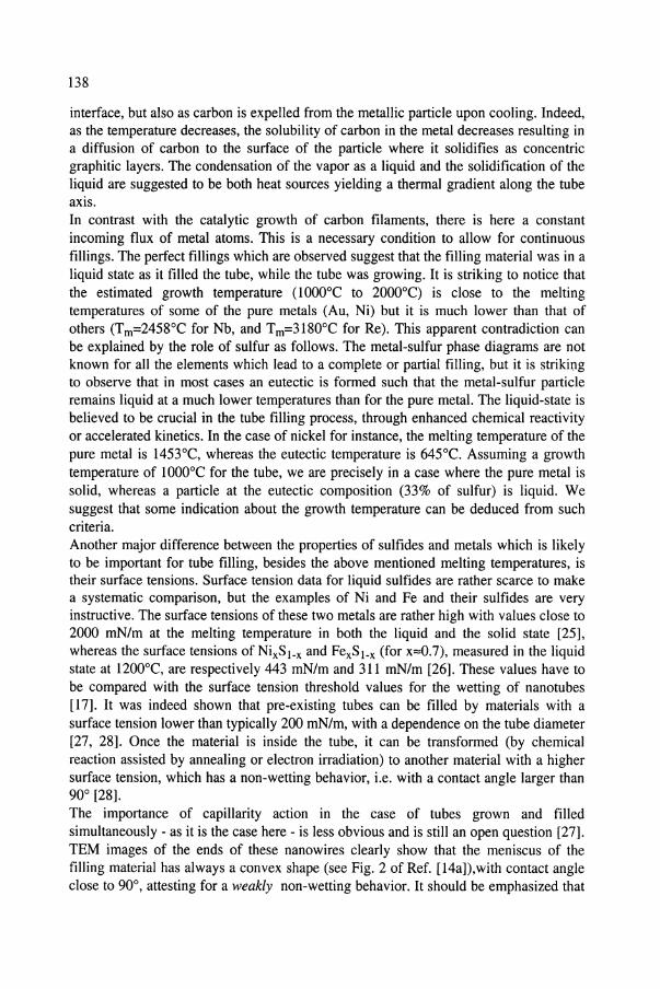
In some other cases as the case of Ni-based nanowires shown in Fig.2, theconcentration in sulfur is not homogeneous along the tube axis and the filling consistsof a succession of crystallites alternatively pure Ni and nickel sulfides with a S/Ni ratio"" 0.4. The compositional changes are associated with structural and morphologicalchanges of the filling material as shown in Fig.2. In the areas where the S/Ni ratio isapproximately 0.4, it is likely that a metastable sulfide was formed, since no stablenickel sulfide corresponding to such a S/Ni ratio is known. In more S-rich grains, thepseudo cubic compound Ni3Sz corresponding to a S/Ni ratio close to 0.7, was identifiedin certain cases from SAED analyses.
a
~ 05
~O~ ~'-J~ 03v 02So,« oL-........_-J.~--'-~--'-~--'-_..L.-......::""-----'
o 20 40 60 80 100Dislance (rm)
Figure 2 : Analysis of a filled nanotube obtained with a 99.4% graphite anode doped with Ni. Left:longitudinal concentration profiles along the tube axis of C. Ni and S deduced from EELS line-spectrarecorded by scanning the probe along the wire axis. The filling material is alternatively pure Ni and a nickelsulfide. Right: HRTEM image of a nanowire showing a nickel crystallite inside between two nickel sulfidegrains (or inside a nickel-sulfide matrix). Grain boundaries are arrowed.
137
The only exception to this spectacular concentration phenomenon of sulfur inside thenanotubes was observed for Ge: SAED and HRTEM analyses lead to the conclusionthat the nanowires have the structure of pure Ge.In order to understand the roles played by sulfur and the metal, we performed two kindsof experiments using in both cases high purity carbon rods (99.997%). We firstsuccessively doped the anode with Co (99.99%), Ni (99.9%), Cr (99.95%), Dy (99.9%)and S (sublimed). The other experimental conditions were unchanged [23]. It is strikingthat no filled nanotube was found in the cathode deposit. Co and Ni yielded theformation of single-walled nanotubes as usually observed [I] whereas only emptymulti-walled nanotubes were produced with Cr, Dy and S.In the second kind of experiments, we focused on the case of Cr which produced thelongest nanowires and we added sulfur to Cr in a S/Cr=O.5% atomic ratio (i.e.S/C=O.I % in weight). This doping resulted in the abundant formation on the cathode oftrue nanowires encapsulated in carbon nanotubes similar to those obtained previously.EELS nanoanalysis revealed that some nanowires contained sulfur as those obtainedwith the 99.4% graphite rods but for a majority of them, the fraction of sulfur wasbelow the limit of detection of the spectrometer [23].All these results prove that sulfur is crucial for filling carbon nanotubes with Cr andthat pure Cr nanowires are formed when S is added in catalytic quantity.
3.3 GROWTH MECHANISM AND THE ROLE OF SULFUR
There are obvious similarities between the present filled nanotubes and the carbonfilaments grown by decomposition of gaseous hydrocarbons on catalytic particles [22].First, it is likely that, in view of the typical filling length, filling does not occur after thegrowth of the nanotube is achieved: the nanotube is being filled - by a material which ismost likely initially in a liquid state - while it is still growing. Therefore carbon and themetal are intimately related in the growth process, as in the case of the growth ofcarbon filaments. Second, the temperature in the very specific localized regions of thecathode where filled nanotubes are found is estimated to be rather low (betweenlOOO°C and 2000°C) compared to that for the deposit facing the anode. Thistemperature range is comparable, although slightly higher, to that for the catalyticgrowth of carbon filaments. Finally, filled nanotubes, in particular those partially filled[14], display morphological similarities with carbon filaments [22]. For these reasons,the vapor-liquid-solid (VLS) scheme, generally adopted to describe the catalytic growthof carbon filaments [24], will be also used here to discuss the growth of fillednanotubes.We will concentrate on the steady-state regime of the combined growth of the nanowireand the nanotube, the initial stage being a separate problem. We propose that a Iiquidlike metallic particle is attached to the growing end of the nanotube. The size of thisparticle may vary from the diameter of the tube to much larger dimensions. Thisparticle contains metal, carbon and sulfur atoms which are incorporated either by directcondensation from the vapor phase, or by diffusion from the surface of the tube. Thetube grows as carbon atoms come to complete the graphitic network at the particle/tube
138
interface, but also as carbon is expelled from the metallic particle upon cooling. Indeed,as the temperature decreases, the solubility of carbon in the metal decreases resulting ina diffusion of carbon to the surface of the particle where it solidifies as concentricgraphitic layers. The condensation of the vapor as a liquid and the solidification of theliquid are suggested to be both heat sources yielding a thermal gradient along the tubeaxis.In contrast with the catalytic growth of carbon filaments, there is here a constantincoming flux of metal atoms. This is a necessary condition to allow for continuousfillings. The perfect fillings which are observed suggest that the filling material was in aliquid state as it filled the tube, while the tube was growing. It is striking to notice thatthe estimated growth temperature (lOOO°C to 2000°C) is close to the meltingtemperatures of some of the pure metals (Au, Ni) but it is much lower than that ofothers (Tm=2458°C for Nb, and Tm=3180°C for Re). This apparent contradiction canbe explained by the role of sulfur as follows. The metal-sulfur phase diagrams are notknown for all the elements which lead to a complete or partial filling, but it is strikingto observe that in most cases an eutectic is formed such that the metal-sulfur particleremains liquid at a much lower temperatures than for the pure metal. The liquid-state isbelieved to be crucial in the tube filling process, through enhanced chemical reactivityor accelerated kinetics. In the case of nickel for instance, the melting temperature of thepure metal is 1453°C, whereas the eutectic temperature is 645°C. Assuming a growthtemperature of 1000°C for the tube, we are precisely in a case where the pure metal issolid, whereas a particle at the eutectic composition (33% of sulfur) is liquid. Wesuggest that some indication about the growth temperature can be deduced from suchcriteria.Another major difference between the properties of sulfides and metals which is likelyto be important for tube filling, besides the above mentioned melting temperatures, istheir surface tensions. Surface tension data for liquid sulfides are rather scarce to makea systematic comparison, but the examples of Ni and Fe and their sulfides are veryinstructive. The surface tensions of these two metals are rather high with values close to2000 mN/m at the melting temperature in both the liquid and the solid state [25],whereas the surface tensions of NixS1_x and FexSl.x (for x::::0.7), measured in the liquidstate at 1200°C, are respectively 443 mN/m and 311 mN/m [26]. These values have tobe compared with the surface tension threshold values for the wetting of nanotubes[17]. It was indeed shown that pre-existing tubes can be filled by materials with asurface tension lower than typically 200 mN/m, with a dependence on the tube diameter[27, 28]. Once the material is inside the tube, it can be transformed (by chemicalreaction assisted by annealing or electron irradiation) to another material with a highersurface tension, which has a non-wetting behavior, Le. with a contact angle larger than90° [28].The importance of capillarity action in the case of tubes grown and filledsimultaneously - as it is the case here - is less obvious and is still an open question [27].TEM images of the ends of these nanowires clearly show that the meniscus of thefilling material has always a convex shape (see Fig. 2 of Ref. [14a]),with contact angleclose to 90°, attesting for a weakly non-wetting behavior. It should be emphasized that
139
the wetting behavior under the synthesis conditions (i.e. at high temperature and with afilling material likely to be liquid) may differ from that under the observationconditions, i.e. at ambient temperature and in the solid state. Even if the tubes are notfilled by capillarity action, it is clear that a large surface tension is a strong drivingforce against filling in particular in the case of liquid fillings. A liquid with a largesurface tension, such as a transition metal liquid, emerging at an open end of a tube willindeed be sucked out. The values of the surface tension of liquid sulfides of iron andnickel reported above are much lower than that of pure transition metals and are closeto the threshold value estimated for nanotube wetting. It is therefore suggested that,compared to a situation without sulfur, the addition of sulfur will cancel the strongdriving force against filling, by drastically reducing the surface tension.Sulfur may also favor the formation of the tubes, since it is known to promote thegraphitization of carbon materials below 2000°C by acting as a cross-linker [29].Finally sulfur may favor the wetting between the tube and the filling material, inparticular through the sulfur atoms which are released after the graphitization process.The very high sulfur-concentration observed in the filling material can be explainedfirst by its very strong affinity with metals. In the present scheme, the liquid-likemetallic particle is therefore rich in sulfur (at least in average, as we will discuss later inthe case of Cr). The sulfur atoms which are released by the carbon layers after thegraphitization process, also contributes to increase this concentration proportionally tothe number of carbon layers.The final microstructure and chemical composition of the nanowires are governed bythe cooling conditions and by the thermodynamics dictated by the phase diagram. Thedispersion observed in the microstructures can be explained by different cooling rates(as a function of the position in the reaction chamber for instance): a rapid quench willlead to a microcrystalline filling whereas a slow solidification will lead to a directionalsolidification front allowing the growth of long single-crystals. Two types ofheterogeneities in chemical composition have been observed: either within a given tubefor some filling elements or from one tube to the other for other filling elements. Wedemonstrate below that these two radically different situations correspond to two typesof sulfur-metal phase diagrams and that this result can be simply explained followingthe solidification process of the sulfur-metal particle.We first consider the schematic phase diagram drawn in Fig. 3(a). It is a simplifiedrepresentation of the phase diagrams of S-M systems where M is a metal such as Ni,Co, Fe, Pd [30]. Sulfur is soluble in the liquid phase but not in the solid metallic phase,leading to the existence of different sulfides, S I, S2... , depending on the concentrationin sulfur. As the solidification starts upon cooling, small crystallites of pure metal startto nucleate within the liquid phase. As the temperature decreases these crystallites growand the sulfur concentration in the liquid increases, until the eutectic temperature isreached. At this point, the liquid is at a composition close to S 1 and almost totallytransforms into a S 1 solid. This scenario perfectly explains why one finds crystals ofpure metal surrounded by a sulfide crystal, and exactly corresponds to the situationillustrated in Fig. 2 in the case of Ni. In the case where the nucleation of metalcrystallites in the liquid is too slow, another scheme accounting for this variation of

140
composition has been proposed previously [15]. It is based on the idea of an alternativegrowth of the M and S1 solids: when the metal grows the sulfur concentration in theliquid increases until it approaches the S1 composition; then S1 crystallizes, but itssulfur concentration being larger than the average sulfur concentration in the liquid, thepropagation of the solidification front creates a depletion of sulfur in the liquid close tothe liquid-solid interface; therefore another cycle starts with the crystallization of themetal etc... Note that in the latter scheme a temperature gradient along the tube must beassumed, while the first scheme can be generalized to a homogeneous cooling of thewhole tube.
M 81 82 Concentrationin sulfur
M
(b)
81 Concentrationin sulfur
Figure 3: Simplified representation ofmetal-sulfur phase diagrams and their impact on the filling of tubes. a): eutectic-type phase diagrams typical of metals like Ni, Co, Fe ; SI and S2 are definite sulfides. b) :immiscible-liquid type phase diagram typical of metals like Cr or Ge ; the phase separation inside a liquidwith an initial composition indicated by the dashed arrow leads to two solidification routes indicated by thevertical arrows.
We now consider the schematic phase diagram drawn in Fig. 3(b), occurring forelements such as Cr and Ge [30]. The difference with the previous case lies in theexistence of a miscibility gap in the liquid. There are indeed two liquid phases: analmost pure-metal liquid phase L1 and a S-rich liquid phase L2. These two liquidphases will tend to phase separate. This phase separation within the liquid phase, i.e.before the filling occurs, is very different from the previous situation where the phaseseparation occurs once the liquid is inside the tube. In the present case the tubes will befilled over very long lengths either by the liquid L1 - which once crystallized yields afilling by the pure metal - or by the liquid L2, with a composition close to a definitesulfide such as SI, which will constitute the main material after solidification. Thisprocess nicely accounts for the two kinds of fillings observed in the case of Cr (CrS orpure Cr) in the experiment where the anode was doped by trace amounts of sulfur. In
141
the experiment with the 99.4% graphite, the amount of sulfur is higher so that the L2liquid phase is dominant and consequently only Cr-S sulfides were detected.
In conclusion we have shown that the presence of sulfur in catalytic quantity is crucialfor the arc-discharge production of abundant fillings of nanotubes by metal basednanowires. It is suggested that sulfides are more favourable than pure metals fornanotube fillings because they have a lower solidification temperature and a muchlower surface tension. Other elements than sulfur, such as selenium, hydrogen, oxygen,may have a similar effect on the filling process. It is striking that using an hydrogen arc,very similar Ge nanowires have been produced [31]. Furthermore the discussion of thegrowth mechanism has shown that the "metallurgy" of nanowires can be understood byconsidering the equilibrium phase diagrams of the corresponding metal-sulfur systemand that the microstructures result from a directional solidification of a liquid phase.
4. BN-C nanotubes
4.1 STRUCTURAL ANALYSIS
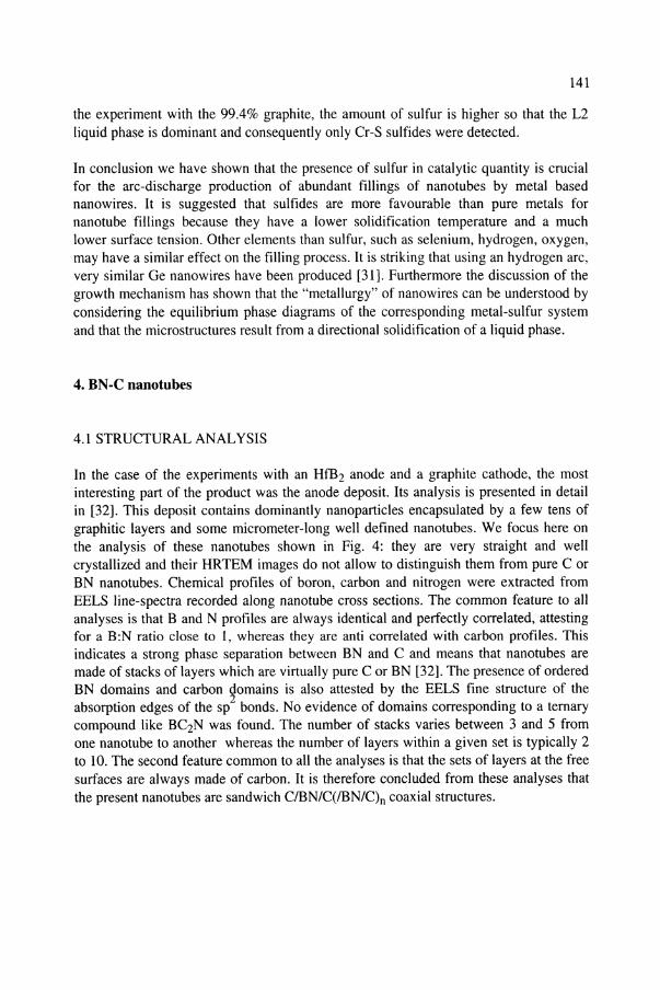
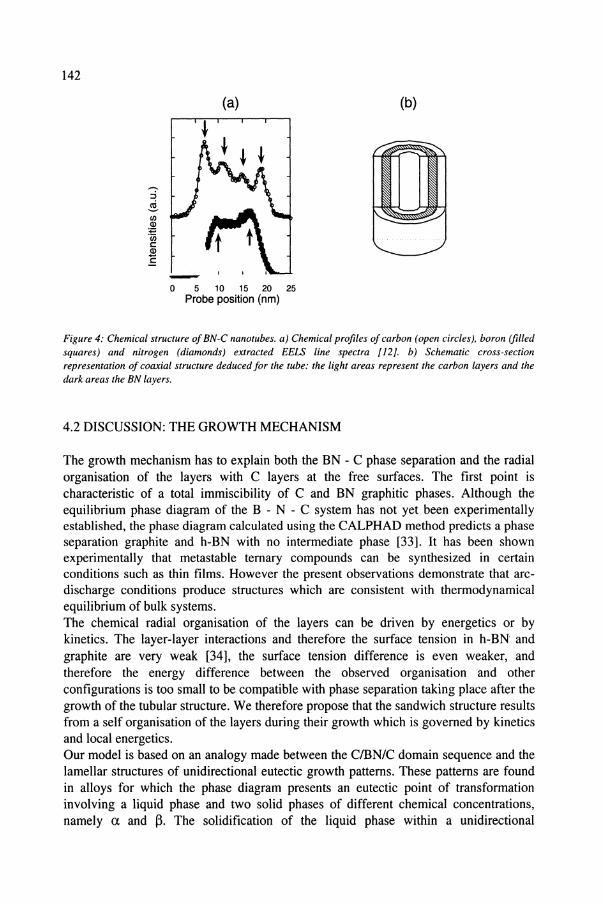
In the case of the experiments with an HfB2 anode and a graphite cathode, the mostinteresting part of the product was the anode deposit. Its analysis is presented in detailin [32]. This deposit contains dominantly nanoparticles encapsulated by a few tens ofgraphitic layers and some micrometer-long well defined nanotubes. We focus here onthe analysis of these nanotubes shown in Fig. 4: they are very straight and wellcrystallized and their HRTEM images do not allow to distinguish them from pure C orBN nanotubes. Chemical profiles of boron, carbon and nitrogen were extracted fromEELS line-spectra recorded along nanotube cross sections. The common feature to allanalyses is that Band N profiles are always identical and perfectly correlated, attestingfor a B:N ratio close to 1, whereas they are anti correlated with carbon profiles. Thisindicates a strong phase separation between BN and C and means that nanotubes aremade of stacks of layers which are virtually pure C or BN [32]. The presence of orderedBN domains and carbon domains is also attested by the EELS fine structure of theabsorption edges of the sp2 bonds. No evidence of domains corresponding to a ternarycompound like BC2N was found. The number of stacks varies between 3 and 5 fromone nanotube to another whereas the number of layers within a given set is typically 2to 10. The second feature common to all the analyses is that the sets of layers at the freesurfaces are always made of carbon. It is therefore concluded from these analyses thatthe present nanotubes are sandwich CIBN/C(IBN/C)n coaxial structures.
142
(b)
o 5 10 15 20 25Probe position (nm)
Figure 4: Chemical structure of BN-C nanotubes. a) Chemical profiles of carbon (open circles), boron (filledsquares) and nitrogen (diamonds) extracted EELS line spectra [12]. b) Schematic cross-sectionrepresentation of coaxial structure deduced for the tube: the light areas represent the carbon layers and thedark areas the BN layers.
4.2 DISCUSSION: THE GROWTH MECHANISM
The growth mechanism has to explain both the BN - C phase separation and the radialorganisation of the layers with C layers at the free surfaces. The first point ischaracteristic of a total immiscibility of C and BN graphitic phases. Although theequilibrium phase diagram of the B - N - C system has not yet been experimentallyestablished, the phase diagram calculated using the CALPHAD method predicts a phaseseparation graphite and h-BN with no intermediate phase [33]. It has been shownexperimentally that metastable ternary compounds can be synthesized in certainconditions such as thin films. However the present observations demonstrate that arcdischarge conditions produce structures which are consistent with thermodynamicalequilibrium of bulk systems.The chemical radial organisation of the layers can be driven by energetics or bykinetics. The layer-layer interactions and therefore the surface tension in h-BN andgraphite are very weak [34], the surface tension difference is even weaker, andtherefore the energy difference between the observed organisation and otherconfigurations is too small to be compatible with phase separation taking place after thegrowth of the tubular structure. We therefore propose that the sandwich structure resultsfrom a self organisation of the layers during their growth which is governed by kineticsand local energetics.Our model is based on an analogy made between the CIBNlC domain sequence and thelamellar structures of unidirectional eutectic growth patterns. These patterns are foundin alloys for which the phase diagram presents an eutectic point of transformationinvolving a liquid phase and two solid phases of different chemical concentrations,namely a and /1 The solidification of the liquid phase within a unidirectional
143
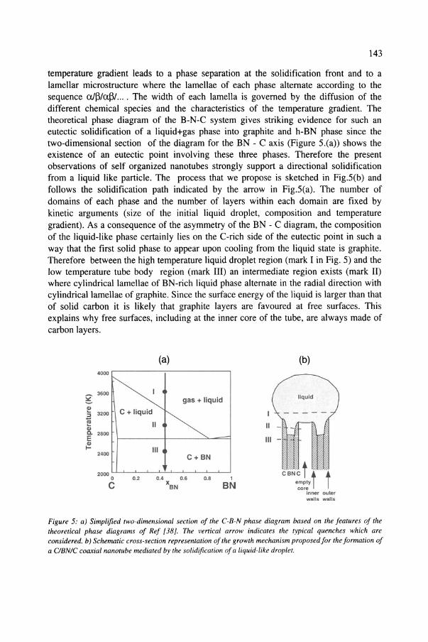
temperature gradient leads to a phase separation at the solidification front and to alamellar microstructure where the lamellae of each phase alternate according to thesequence aI~/a.~1... . The width of each lamella is governed by the diffusion of thedifferent chemical species and the characteristics of the temperature gradient. Thetheoretical phase diagram of the B-N-C system gives striking evidence for such aneutectic solidification of a liquid+gas phase into graphite and h-BN phase since thetwo-dimensional section of the diagram for the BN - C axis (Figure 5.(a» shows theexistence of an eutectic point involving these three phases. Therefore the presentobservations of self organized nanotubes strongly support a directional solidificationfrom a liquid like particle. The process that we propose is sketched in Fig.5(b) andfollows the solidification path indicated by the arrow in Fig.5(a). The number ofdomains of each phase and the number of layers within each domain are fixed bykinetic arguments (size of the initial liquid droplet, composition and temperaturegradient). As a consequence of the asymmetry of the BN - C diagram, the compositionof the liquid-like phase certainly lies on the C-rich side of the eutectic point in such away that the first solid phase to appear upon cooling from the liquid state is graphite.Therefore between the high temperature liquid droplet region (mark I in Fig. 5) and thelow temperature tube body region (mark III) an intermediate region exists (mark II)where cylindrical lamellae of BN-rich liquid phase alternate in the radial direction withcylindrical lamellae of graphite. Since the surface energy of the liquid is larger than thatof solid carbon it is likely that graphite layers are favoured at free surfaces. Thisexplains why free surfaces, including at the inner core of the tube, are always made ofcarbon layers.
(b)(a)4000
~ 3500
?! gas + liquidQI
C + liquid:; 3200 I
~ II IIQIC. 2800EQI~ III
2400 C+BN
20000 0.2 0.4 0.6 0.8 1
C xBN BN
c~c tt temptycore
inner outorwalls walls
Figure 5: a) Simplified two-dimensional section of the C-B-N phase diagram based on the features of thetheoretical phase diagrams of Ref [38]. The vertical arrow indicates the typical quenches which areconsidered. b) Schematic cross-section representation ofthe growth mechanism proposed for the formation ofa ClBN/C coaxial nanotube mediated by the solidification ofa liquid-like droplet.
144
In conclusion on this part, we have shown that the arc-discharge method modified toprovide carbon, boron and nitrogen from separate sources leads to the formation ofmultiwall nanotubes characterized by a phase separation between BN and C phases anda radial self organization of the layers. All these features can be understood byconsidering the thermodynamic phase diagrams and the formation of these nanotubes isproposed to be governed by a kinetic path of solidification of a fluid droplet. Since it isbased on thermodynamical considerations, the present scheme has a predictive powerand could be used for synthesizing tubes with anticipated composition and structure.
5. General discussion: clues for the formation of nanotubes
We have presented in this paper the study of two very different kinds of multi-elementstubular structures, namely nanotubes filled with metallic nanowires and composite BNC nanotubes, and suggested for both of them a coherent growth scheme to explain theirchemical and crystalline structure. It is very striking that, in spite of the obviousdifferences between the two systems, similar physical processes are found to accountfor their formation. In both cases, the observed structures have the particularity of beingthermodynamically quite stable although these systems are far from being true bulkmaterials and are grown far from bulk equilibrium conditions. The observed crystallinephases have indeed been identified as known stable phases except in a few cases, andthe microstructures are consistent with local energetic minima. This tends to prove thatthe formation temperatures are high enough to achieve local equilibrium within theevolution time scale and that the systems are large enough to behave as threedimensional systems. This perhaps makes the difference between nanotubular structuresand other nanoscale systems like thin layered structures which are synthesized at muchlower temperatures. It is although worth noting that the cylindrical structure, and inparticular the curvature of the graphene sheets, doesn't seem to modify significantly thethermodynamic data. Furthermore, the fact that considerations based on equilibriumphase diagrams account very well for the observed microstructures, strongly supportsthe assumed growth mechanisms. In both kinds of systems, we suggest a formationmediated by a liquid like particle and its directional solidification. The temperaturegradient within the reactor chamber is rather weak at the scale of a nanotube, but thecooling of the particle may explain a significant temperature gradient from the inside ofthe particle to the outside and the tube. In the case of filled-nanotubes, the mediation bya liquid particle implies that the solidification temperature of the related system is lowerthan the formation temperature. Adding sulfur to a metal decreases the meltingtemperature as well as the surface tension, thus explaining why sulfur favors tubefillings. The self-organisation between BN and C layers in the case of the B-C-Nnanotubes studied here is proposed to be governed by a sequential solidification of thetwo phases, following the characteristics of the BN-C phase diagram. One can in tumconsider using these phase diagrams to adjust the synthesis conditions in order toproduce other tubular nanostructures.
145
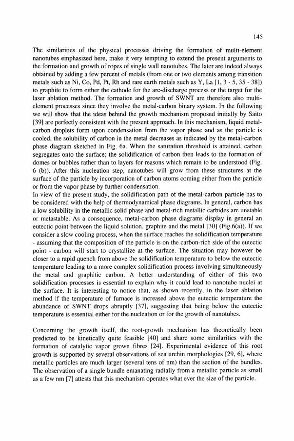
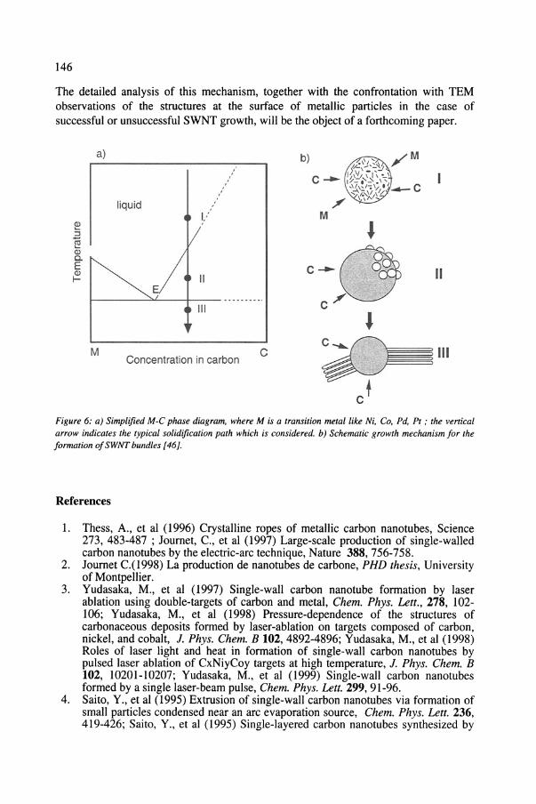
The similarities of the physical processes driving the formation of multi-elementnanotubes emphasized here, make it very tempting to extend the present arguments tothe formation and growth of ropes of single wall nanotubes. The later are indeed alwaysobtained by adding a few percent of metals (from one or two elements among transitionmetals such as Ni, Co, Pd, Pt, Rh and rare earth metals such as Y, La [1, 3 - 5, 35 - 38])to graphite to form either the cathode for the arc-discharge process or the target for thelaser ablation method. The formation and growth of SWNT are therefore also multielement processes since they involve the metal-carbon binary system. In the followingwe will show that the ideas behind the growth mechanism proposed initially by Saito[39] are perfectly consistent with the present approach. In this mechanism, liquid metalcarbon droplets form upon condensation from the vapor phase and as the particle iscooled, the solubility of carbon in the metal decreases as indicated by the metal-carbonphase diagram sketched in Fig. 6a. When the saturation threshold is attained, carbonsegregates onto the surface; the solidification of carbon then leads to the formation ofdomes or bubbles rather than to layers for reasons which remain to be understood (Fig.6 (b». After this nucleation step, nanotubes will grow from these structures at thesurface of the particle by incorporation of carbon atoms coming either from the particleor from the vapor phase by further condensation.In view of the present study, the solidification path of the metal-carbon particle has tobe considered with the help of thermodynamical phase diagrams. In general, carbon hasa low solubility in the metallic solid phase and metal-rich metallic carbides are unstableor metastable. As a consequence, metal-carbon phase diagrams display in general aneutectic point between the liquid solution, graphite and the metal [30] (Fig.6(a». If weconsider a slow cooling process, when the surface reaches the solidification temperature- assuming that the composition of the particle is on the carbon-rich side of the eutecticpoint - carbon will start to crystallize at the surface. The situation may however becloser to a rapid quench from above the solidification temperature to below the eutectictemperature leading to a more complex solidification process involving simultaneouslythe metal and graphitic carbon. A better understanding of either of this twosolidification processes is essential to explain why it could lead to nanotube nuclei atthe surface. It is interesting to notice that, as shown recently, in the laser ablationmethod if the temperature of furnace is increased above the eutectic temperature theabundance of SWNT drops abruptly [37], suggesting that being below the eutectictemperature is essential either for the nucleation or for the growth of nanotubes.
Concerning the growth itself, the root-growth mechanism has theoretically beenpredicted to be kinetically quite feasible [40] and share some similarities with theformation of catalytic vapor grown fibres [24]. Experimental evidence of this rootgrowth is supported by several observations of sea urchin morphologies [29, 6], wheremetallic particles are much larger (several tens of nm) than the section of the bundles.The observation of a single bundle emanating radially from a metallic particle as smallas a few nm [7] attests that this mechanism operates what ever the size of the particle.
146
The detailed analysis of this mechanism, together with the confrontation with TEMobservations of the structures at the surface of metallic particles in the case ofsuccessful or unsuccessful SWNT growth, will be the object of a forthcoming paper.
b)
CConcentration in carbon
liquid
,,
a)
M
I------~'-----+--- -- - --- - -_.
Figure 6: a) Simplified M-C phase diagram. where M is a transition metal like Ni. Co, Pd. Pt ; the verticalarrow indicates the typical solidification path which is considered. b) Schematic growth mechanism for theformation ofSWNT bundles [46].
References
1. Thess, A., et al (1996) Crystalline ropes of metallic carbon nanotubes, Science273, 483-487 ; Journet, c., et al (1997) Large-scale production of single-walledcarbon nanotubes by the electric-arc technique, Nature 388, 756-758.
2. Journet C.(l998) La production de nanotubes de carbone, PHD thesis, Universityof Montpellier.
3. Yudasaka, M., et al (1997) Single-wall carbon nanotube formation by laserablation using double-targets of carbon and metal, Chern. Phys. Lett., 278, 102106; Yudasaka, M., et al (1998) Pressure-dependence of the structures ofcarbonaceous deposits formed by laser-ablation on targets composed of carbon,nickel, and cobalt, J. Phys. Chern. B 102, 4892-4896; Yudasaka, M., et al (1998)Roles of laser light and heat in formation of single-wall carbon nanotubes bypulsed laser ablation of CxNiyCoy targets at high temperature, J. Phys. Chern. B102, 10201-10207; Yudasaka, M., et al (1999) Single-wall carbon nanotubesformed by a single laser-beam pulse, Chern. Phys. Lett. 299,91-96.
4. Saito, Y., et al (1995) Extrusion of single-wall carbon nanotubes via formation ofsmall particles condensed near an arc evaporation source, Chern. Phys. Lett. 236,419-426; Saito, Y., et al (1995) Single-layered carbon nanotubes synthesized by
147
catalytic assistance of rare-earths in a carbon-arc, J. Phys. Chem. 99, 1607616079; Saito, Y., et al (1998) High yield of single-wall carbon nanotubes by arcdischarge using Rh-Pt mixed catalysts, Chem. Phys. Lett. 294, 593-598.
5. Kataura, H., et al (1998) Formation of thin single-wall carbon nanotubes by laservaporization of RhlPd-graphite composite rod, Jpn J. Appl. Phys. 37, L616-618.
6. Seraphin, S., and Zhou, D. (1994) Single-walled carbon nanotubes produced athigh-yield by mixed catalysts, Appl. Phys. Lett. 64, 2087-2089, Zhou, D., et al(1994) Appl. Phys. Lett. 65, 181.
7. For reviews see: Bernholc, 1., et al (1998) Theory of growth and mechanicalproperties of nanotubes, Appl. Phys. A 67, 39-46 ; Charlier, J.Ch., et al (1999)Microscopic growth mechanisms for carbon and boron-nitride nanotubes, Appl.Phys. A 68, 267-273.
8. Arepalli,S., and Scott, C. D. (1999) Spectral measurements in production ofsingle-wall carbon nanotubes by laser ablation, Chem. Phys. Lett. 302, 139-145;Arepalli, S., et al (2000) Diagnostics of laser-produced plume under carbonnanotube growth conditions, Appl. Phys. A 70, 125-133.
9. Kokai, F., et al (1999) Growth dynamics of single-wall carbon nanotubessynthesized by CO laser vaporization, J. Phys. Chem. B 103, 4346-4351.
10. Kataura, H., et al dOOO), Carbon 38, 1691-1687; Ishigaki, T., Suzuki,S., Kataura,H., Kratschmer, W., and Achiba, Y. (2000) Characterization of fullerenes andcarbon nanoparticles generated with a laser-furnace technique, Appl. Phys. A 70,121-124.
11. Puretzki, A.A., Geohegan, D.B., Fan, X., and Pennycook, SJ. (2000) Dynamicsof single-wall carbon nanotube synthesis by laser vaporization, Appl. Phys. A 70,153-160.
12. Journet, c., and Bernier, P. (1998) Production of carbon nanotubes, Appl. Phys. A67,1-9.
13. Terrones, M., et al (1999) Nanotubes: a revolution in materials science andelectronics, Topics in Current Chemistry 199, (Springer Verlag, Berlin), p.190.
14. Guerret-Piecourt, c., Le Bouar, Y., Loiseau, A., and Pascard, H. (1994) Relationbetween metal electronic structure and morphology of metal compounds insidecarbon nanotubes, Nature 372, 761-765; Loiseau, A., and Pascard, H. (1996)Synthesis of long carbon nanotubes filled with Se, S, Sb and Ge by the arcmethod, Chem. Phys. Lett. 256, 246-252.
15. Loiseau, A., et al (2000) Filling carbon nanotubes using an arc discharge, inScience and applications of nanotubes. D. Tomanek and R. J. Enbody (Eds),Kluwer Academic Press, New York, pp. 1-16.
16. Lee, S.T., et al (1999) Oxide-assisted semiconductor nanowire growth, MRSBulletin 24(8), 36-42; Terrones, M., et al (1999) Advances in the creation of fillednanotubes and novel nanowires, MRS Bulletin 24(8), 43-49.
17. Ugarte, D., et al (1998) Filling carbon nanotubes, Appl. Phys. A 67,101-105.18. Suenaga, K., Colliex, c., Demoncy, N., Loiseau, A., Pascard, H., and Willaime,
F. (1997) Synthesis of nanoparticles and nanotubes with well-separated layers ofboron nitride and carbon, Science 278, 653-655.
19. Loiseau, A., Willaime, F., Demoncy, N., Hug, G., and Pascard, H. (1996) Boronnitride nanotubes with reduced numbers of layers synthesized by arc discharge,Phys. Rev. Lett. 76,4737-4740. For a review see Loiseau, A., et al (1998) Boronnitride nanotubes, Carbon 36, 743-752.
20. Stephan, 0., et al (1994) Doping graphitic and carbon nanotubes structures withboron and nitrogen, Science 266, 1683-1685; Z. Weng-Sieh et al (1995) Synthesisof B C N Nanotubes, Phys. Rev. B 51, 11229-11232; Terrones, M., et al (1996)Pyro1yfic:lly grown BxCyNz nanomaterials - nanofibres and nanotubes, Chern.
148
Phys. Lett. 257, 576-582; Redlich, Ph., et al (1996) B-C-N nanotubes and borondoping of carbon Nanotubes, Chern. Phys. Lett. 260, 465-470.
21. Tence, M., Quartuccio, M., and Colliex, e. (1995) PEELS compositionalprofiling and mapping at nanometer spatial-resolution, Ultramicroscopy 58, 4254.
22. Audier, M., Oberlin, A., and Coulon, M.l. (1981) Crystallographic orientations ofcatalytic particles in filamentous carbon: case of simple conical particles, J. ofCryst. Growth 55, 549-556; Baker, R.T.K., Barber, M.A., Harris, P.S., Feates,F.S., and Waite, R.I. (1972) Nucleation and growth of carbon deposit from thenickel catalyzed decomposition of acetylene, J. Catal. 26, 51-62.
23. Demoncy, N., Stephan, 0., Brun, N., Colliex, C., Loiseau, A., Pascard, H. (1998)Filling carbon nanotubes with metals by the arc-discharge method: the key role ofsulfur, Eur. Phys. J. B 4, 147-157.
24. Tibbetts, G. (1984) Why are carbon filaments tubular?, J. Cryst. Growth 66,632638.
25. Kumikov, V.K and Khokonov, Kh. B. (1983) J. Appl. Phys. 54, 1346.26. Ip, S.W., and Toguri, J.M. (1993) Surface and interfacial-tension of the Ni-Fe-S,
Ni-Cu-S, and fayalite slag systems, Metallurgical Transactions B 24,657-668.27. Dujardin, E., Ebbesen, T.W., Hiura, H., and Tanigaki, K. (1994) Capillarity and
wetting of carbon nanotubes, Science 265, 1850-1852.28. Ugarte, D., Chatelain, A., and de Heer, W.A. (1996) Nanocapillarity and
chemistry in carbon nanotubes, Science 274, 1897-1899.29. Oberlin, A. (1984) Carbonization and graphitization, Carbon 22, 521-541;
Bourrat, X., Oberlin, A., Escalier, l.e. (1987) Fuel 542, 521.30. Massalski, T. B. (1990) Binary Alloy Phase Diagrams, ASM Intemational.31. Dai, J.Y., Lauerhaas, J.M., Setlur, A.A., Chang, R.P.H. (1996) Synthesis of
carbon-encapsulated nanowires using polycyclic aromatic hydrocarbonprecursors, Chern. Phys. Lett. 258,547-53.
32. Suenaga, K., Willaime, F., Loiseau, A., and Colliex, C. (1999) Organisation ofcarbon and boron nitride layers in mixed nanoparticles and nanotubes synthesisedby arc discharge, Appl. Phys. A 68, 301-308.
33. Kasper, B. (1996) PhD thesis, Stuttgart University.34. Schabel, M.e., and Martins, J.L. (1992) Energetics of interplanar binding in
graphite, Phys. Rev. B 46, 7185- 7188.35. Thess, A., et al (1996) Crystalline ropes of metallic carbon nanotubes, Science
273, 483-487; Young Hee, L., Seong Gon, K., Tomanek, D. (1997) Catalyticgrowth of single-wall carbon nanotubes: An ab initio study Phys. Rev. Lett. 78,2393-2396.
36. Joumet, C., et al (1997) Large-scale production of single-walled carbon nanotubesby the electric-arc technique, Nature 388,756-758.
37. Kataura, H. et al (2000), A workshop on nanotubes and fullerenes chemistry,Elsevier Science Ltd, Oxford.
38. Guo, T., et al (1995) Self-assembly of tubular fullerenes, J. Phys. Chern. 99,10694-10697; Guo, T., et al (1995) Catalytic growth of single-walled nanotubesby laser vaporization, Chern. Phys Lett. 243, 49-54.
39. Saito, Y., et al. (1994) Single-wall carbon nanotubes growing radially fron Ni fineparticles formed by arc evaporation, Jpn. J. Appl. Phys. 33, L526-L529; Saito, Y.(1995) Nanoparticles and filled nanocapsules, Carbon 33,979-988.
40. Maiti, A., Brabec, Col., and Bemholc, J. (1997) Kinetics of metal-catalyzedgrowth of single-walled carbon nanotubes, Phys. Rev B 55, R6097-6100.