Embed Size (px)
Citation preview
Scheda elettronica dicontrollo perattuatoriROBO PLUSo CLIMBER
Manuale diistruzione perl’istallatore
Electroniccontrol cardfor ROBOPLUS orCLIMBERactuators
Installationinstruction manual
Centraleélectroniquede contrôlepouractionneursROBO PLUS ouCLIMBERManueld’instructionspour l’installation
ElektronischeSteuerkarte fürKolbentorantriebe ROBOPLUS oderCLIMBER
Installationsanleitu-ngen
Fichaelectrónica decontrol paraaccionadoresROBO PLUS oCLIMBER
Manual deinstrucciones parala instalación
I GB F D E
QUESTO LIBRETTO È DESTINATO SOLO ALL'INSTALLATORE.L'installazione dovrà essere effettuata solamente da personale professionalmente qualificato in conformità a quanto previsto dallalegge n° 46 del 5 marzo 1990 e successive modifiche ed integrazioni e nel pieno rispetto delle norme UNI 8612.
V. 004
INDICE:
Guida rapida : 3Introduzione : 4
Descrizione del prodotto : 4Istruzioni per l’installazione : 5
Schema dei collegamenti : 6Descrizione dei collegamenti : 6Istruzioni per i collegamenti : 7
Limiti della corsa : 8Ricerca iniziale delle quote : 8
Programmazione : 9Memorizzazione dei parametri : 9Programmazione manuale delle quote : 10Programmazione del tempo pausa : 12Cancellazione della memoria : 12
Funzioni selezionabili : 13Prova del funzionamento : 14Descrizione dei modi di funzionamento : 14Scheda “CARICA” per alimentazione a batteria : 15Manutenzione : 15Caratteristiche tecniche della centrale : 15
AVVISO IMPORTANTE:
È nostro dovere ricordare che state eseguendo delle operazioni su impianti di macchine che sono classificati nella categoria dei:"Cancelli e porte automatiche" e quindi considerati particolarmente "Pericolosi"; è vostro compito renderli "Sicuri" per quanto siaragionevolmente possibile!L'installazione ed eventuali interventi di manutenzione devono essere effettuati solo da personale qualificato ed esperto,seguendo le migliori indicazioni dettate dalla "Regola d'arte" ed in conformità a quanto previsto dalle seguenti leggi, norme odirettive:
89/392 CEE (Direttiva macchine)89/336 CEE (Direttiva sulla compatibilità elettromagnetica)73/23 CEE (Direttiva bassa tensione)PrEN 12453 (Sicurezza nell’impiego delle porte motorizzate - requisiti e classificazioni)PrEN 12445 (Sicurezza nell’impiego delle porte motorizzate - metodi di prova)
Nella progettazione e realizzazione dei propri prodotti, Nice , rispetta (per quanto compete alle apparecchiature) tutte questenormative, è fondamentale però che anche l'installatore (per quanto compete agli impianti) prosegua nel rispetto scrupoloso dellemedesime norme.
Personale non qualificato o non a conoscenza delle normative applicabili alla categoria dei "Cancelli e porte automatiche":Deve assolutamente astenersi dall' eseguire installazioni ed impianti
Chi esegue impianti senza rispettare tutte le normative applicabili:Si renderà responsabile di eventuali danni che l'impianto potrà causare!
Italiano
2
GUIDA RAPIDA Non installare il motore senza i necessari “Arresti meccanici della corsa”!
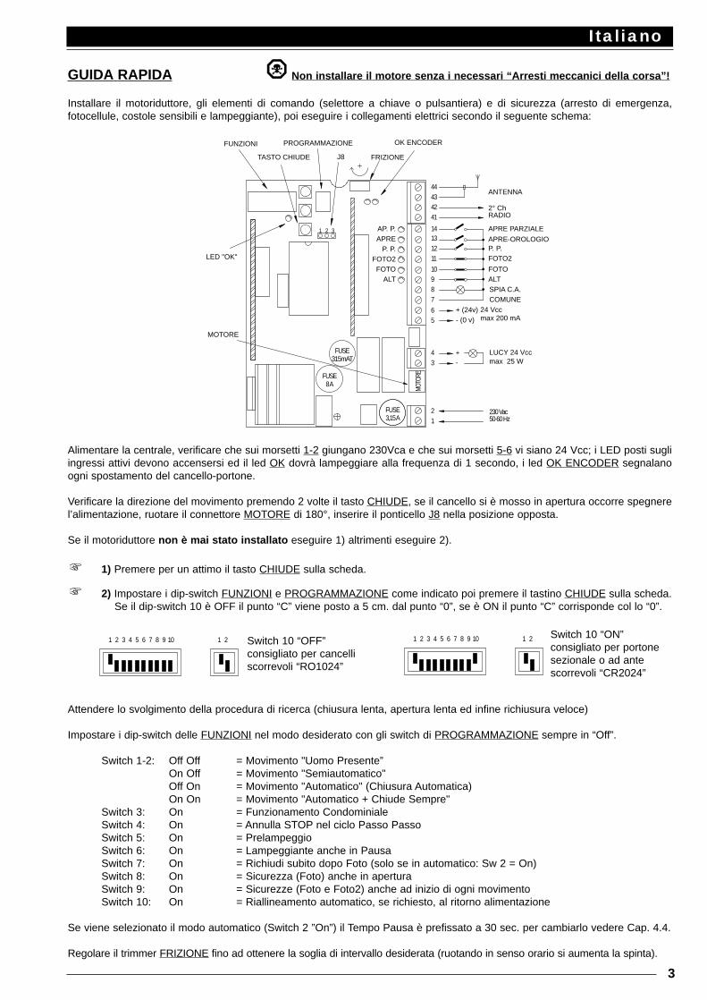
Installare il motoriduttore, gli elementi di comando (selettore a chiave o pulsantiera) e di sicurezza (arresto di emergenza,fotocellule, costole sensibili e lampeggiante), poi eseguire i collegamenti elettrici secondo il seguente schema:
Alimentare la centrale, verificare che sui morsetti 1-2 giungano 230Vca e che sui morsetti 5-6 vi siano 24 Vcc; i LED posti sugliingressi attivi devono accensersi ed il led OK dovrà lampeggiare alla frequenza di 1 secondo, i led OK ENCODER segnalanoogni spostamento del cancello-portone.
Verificare la direzione del movimento premendo 2 volte il tasto CHIUDE, se il cancello si è mosso in apertura occorre spegnerel’alimentazione, ruotare il connettore MOTORE di 180°, inserire il ponticello J8 nella posizione opposta.
Se il motoriduttore non è mai stato installato eseguire 1) altrimenti eseguire 2).
1) Premere per un attimo il tasto CHIUDE sulla scheda.
2) Impostare i dip-switch FUNZIONI e PROGRAMMAZIONE come indicato poi premere il tastino CHIUDE sulla scheda.Se il dip-switch 10 è OFF il punto “C” viene posto a 5 cm. dal punto “0”, se è ON il punto “C” corrisponde col lo “0”.
Attendere lo svolgimento della procedura di ricerca (chiusura lenta, apertura lenta ed infine richiusura veloce)
Impostare i dip-switch delle FUNZIONI nel modo desiderato con gli switch di PROGRAMMAZIONE sempre in “Off”.
Switch 1-2: Off Off = Movimento "Uomo Presente”On Off = Movimento "Semiautomatico"Off On = Movimento "Automatico" (Chiusura Automatica)On On = Movimento "Automatico + Chiude Sempre"
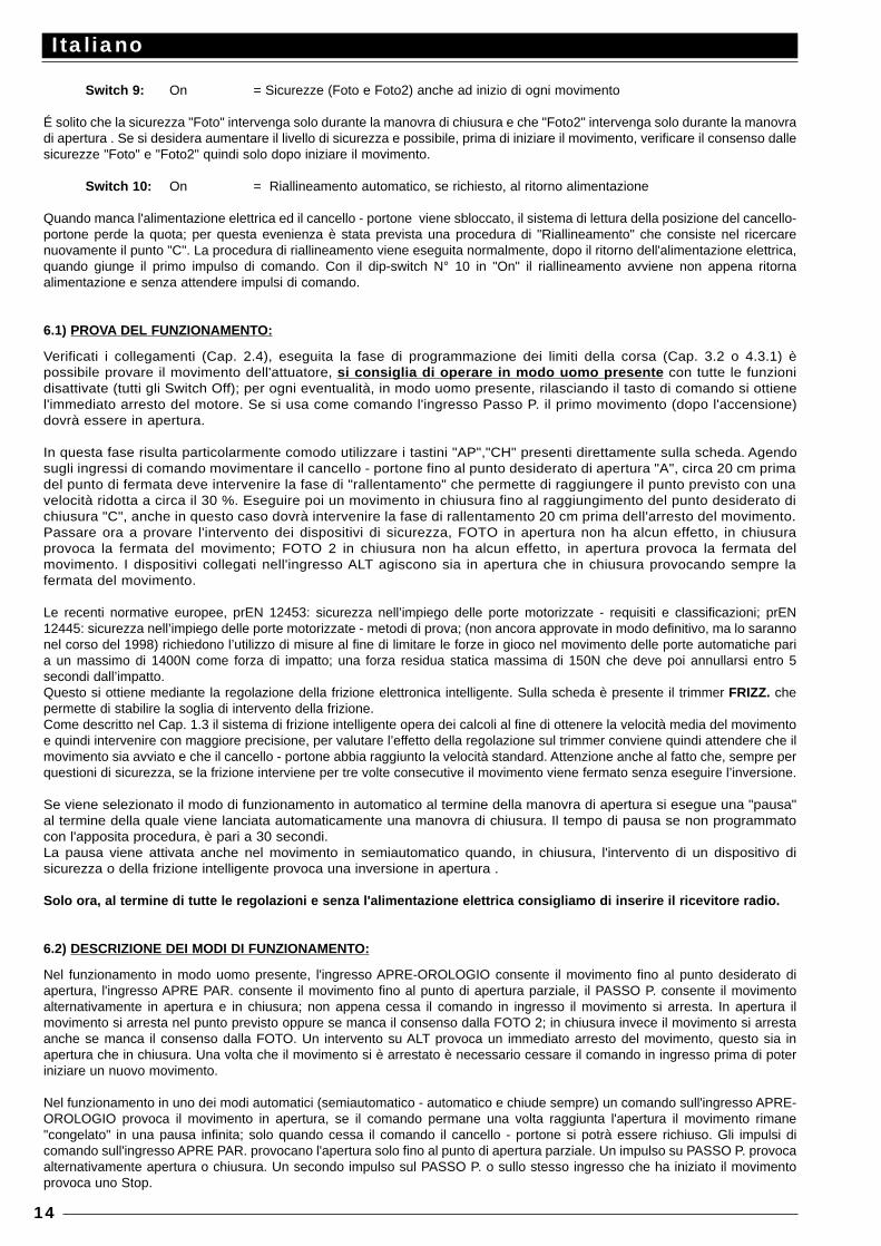
Switch 3: On = Funzionamento CondominialeSwitch 4: On = Annulla STOP nel ciclo Passo PassoSwitch 5: On = PrelampeggioSwitch 6: On = Lampeggiante anche in PausaSwitch 7: On = Richiudi subito dopo Foto (solo se in automatico: Sw 2 = On)Switch 8: On = Sicurezza (Foto) anche in aperturaSwitch 9: On = Sicurezze (Foto e Foto2) anche ad inizio di ogni movimentoSwitch 10: On = Riallineamento automatico, se richiesto, al ritorno alimentazione
Se viene selezionato il modo automatico (Switch 2 ”On”) il Tempo Pausa è prefissato a 30 sec. per cambiarlo vedere Cap. 4.4.
Regolare il trimmer FRIZIONE fino ad ottenere la soglia di intervallo desiderata (ruotando in senso orario si aumenta la spinta).
Italiano
3
24 Vccmax 200 mA- (0 v)
MOTORE
8 A
315mAT
FUSE
FUSE
1MO
TORE
FUSE3,15 A
2
34 +
-
LED "OK"
FUNZIONI
31 2
J8
PROGRAMMAZIONE
TASTO CHIUDE
ALT 98
65
+ (24v)
7
11
FOTO 10
1312
14AP. P.APRE
P. P.FOTO2
41
4342
44
FRIZIONE
OK ENCODER
50-60 Hz230 Vac
LUCY 24 Vccmax 25 W
ALTSPIA C.A.COMUNE
FOTO
FOTO2P. P.APRE-OROLOGIO
APRE PARZIALE
2° ChRADIO
ANTENNA
1 2 3 4 5 6 7 8 9 10 1 2 1 2 3 4 5 6 7 8 9 10 1 2Switch 10 “OFF”consigliato per cancelliscorrevoli “RO1024”
Switch 10 “ON”consigliato per portonesezionale o ad antescorrevoli “CR2024”
1.1) INTRODUZIONE:
La scheda elettronica è prevista per governare l'attuatore ROBO PLUS modello "ROBO 1024" o CLIMBER modello “CR 2024”con motore in corrente continua a 24 V. Si tratta di un progetto di avanzata concezione infatti l'attuatore non dispone deitradizionali finecorsa ma di un sistema di controllo della posizione funzionante mediante lettura ottica dei gradi di rotazionedell'albero; questo rende possibili funzioni non realizzabili con controlli tradizionali. Il raggiungimento del punto previsto avvieneattraverso rallentamento e si ottiene con precisione di pochi millimetri sul punto previsto, viene sempre rilevata la velocità duranteil movimento e quindi ostacoli alla corsa vengono prontamente segnalati con conseguente inversione del moto.
Inoltre la programmazione è veramente un "gioco da ragazzi" infatti avviene in modo completamente automatico, basta premereun tasto ed attendere che un'apposita procedura esegua la misura dei limiti entro i quali deve avvenire il movimento.
Nel progetto sono state adottate le piú avanzate tecniche per garantire la massima immunità nei confronti dei disturbi, lamaggiore flessibilità d'uso e la più vasta scelta di funzioni programmabili, sono possibili azionamenti in modo "uomo presente","semiautomatico" oppure "automatico".Sono previste sofisticate funzioni che vanno dalla "Richiudi subito dopo Foto" passando per la "Richiudi sempre" fino al"Lampeggiante anche in pausa" e di particolari funzioni di tipo operativo "Partenza graduale" e "Rallentamento" inserite di serie,"Freno" di tipo sensibile al contesto che interviene solo se richiesto l'arresto istantaneo del movimento.
La scheda è predisposta per l'inserimento di tutta la gamma di ricevitori radio serie "K","Bio "o"Flo " prodotti da Nice .
1.2) DESCRIZIONE DEL PRODOTTO:
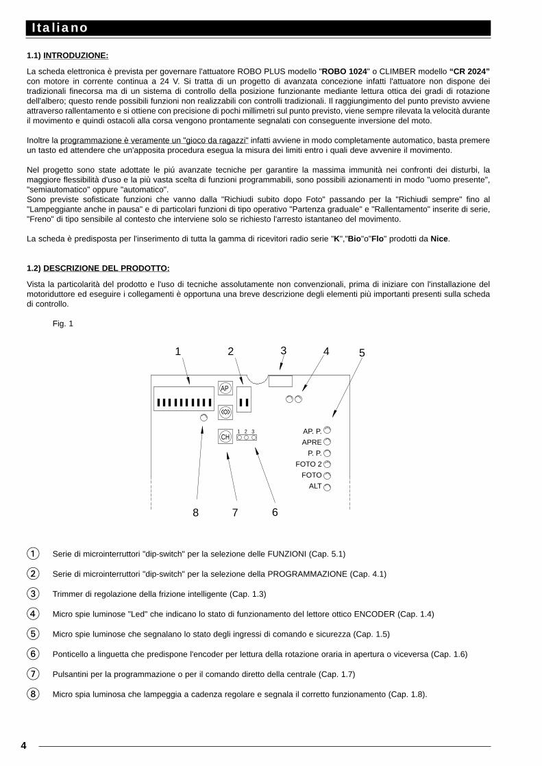
Vista la particolarità del prodotto e l'uso di tecniche assolutamente non convenzionali, prima di iniziare con l'installazione delmotoriduttore ed eseguire i collegamenti è opportuna una breve descrizione degli elementi più importanti presenti sulla schedadi controllo.
Fig. 1
1 Serie di microinterruttori "dip-switch" per la selezione delle FUNZIONI (Cap. 5.1)
2 Serie di microinterruttori "dip-switch" per la selezione della PROGRAMMAZIONE (Cap. 4.1)
3 Trimmer di regolazione della frizione intelligente (Cap. 1.3)
4 Micro spie luminose "Led" che indicano lo stato di funzionamento del lettore ottico ENCODER (Cap. 1.4)
5 Micro spie luminose che segnalano lo stato degli ingressi di comando e sicurezza (Cap. 1.5)
6 Ponticello a linguetta che predispone l'encoder per lettura della rotazione oraria in apertura o viceversa (Cap. 1.6)
7 Pulsantini per la programmazione o per il comando diretto della centrale (Cap. 1.7)
8 Micro spia luminosa che lampeggia a cadenza regolare e segnala il corretto funzionamento (Cap. 1.8).
Italiano
4
31 2CH
68 7
3
AP
<<>>
21 54
AP. P.
APRE
P. P.
FOTO 2
FOTO
ALT
1.3) Frizione intelligente:
Il sistema di lettura ottica della rotazione dell'albero viene utilizzato principalmente per controllare la posizione del cancello -portone durante ilmovimento, attraverso lo stesso sistema si può anche rilevare la velocità del cancello istante per istante.Visto che in un motore in corrente continua la velocità di rotazione e in buona sostanza proporzionale allo sforzo che questo deve sopportare,sviluppare un sistema di rilevazione degli ostacoli, potrebbe apparire piuttosto semplice.Quando la velocità scende al di sotto di un dato limite (regolabile) significa che è applicato uno sforzo oltre la norma e quindi probabilmente c'èun ostacolo. Una soluzione di questo tipo risente però di altri fattori che non hanno nulla a che vedere con gli ostacoli, un banale calo di tensionerischierebbe di far intervenire il sistema, al contrario una tensione superiore provoca un maggiore sforzo prima che il sistema intervenga.Per questi motivi Nice ha sviluppato un proprio sistema di frizione che osiamo definire "intelligente".Durante il movimento viene via via calcolata ed aggiornata quella che potrebbe essere definita "velocità media", rispetto a questa velocità vienecalcolata un certa riduzione (regolabile dal trimmer) che rappresenta la soglia limite di intervento.Con questo metodo se vi fosse per esempio un calo di tensione verrebbe riscontrata una velocità media più bassa e quindi automaticamentesi ridurrebbe anche la soglia di intervento. Se durante il movimento interviene il sistema di frizione viene eseguita una fermata con l'ausilio anche del freno (che toglie la parte residua dienergia cinetica accumulata); poi se è attivo uno dei modi di funzionamento automatico viene avviato un movimento in senso contrario.Comunque per aumentare ulteriormente il livello di sicurezza, se la frizione interviene per tre volte consecutive senza mai raggiungere uno deitermini naturali del movimento viene eseguito uno STOP senza inversione.
1.4) Encoder:
Il movimento del cancello-portone viene rilevato attraverso un sistema di controllo della rotazione dell'albero funzionantemediante lettura ottica delle tacche di una ruota montata nell'albero di trascinamento.Il corretto funzionamento del sistema di lettura può essere verificato mediante due appositi led, quando l'albero viene posto inrotazione questi devono lampeggiare via via che le tacche vengono lette.
1.5) Ingressi:
Quando la centrale è alimentata le spie luminose che sono poste sugli ingressi si accendono se quel particolare ingresso è attivoed è quindi presente la tensione di comando 24 Vcc. Normalmente i led sugli ingressi delle sicurezze FOTO, FOTO2 e ALT sonosempre accesi, mentre quelli sugli ingressi di comando PASSO PASSO, APRE P ed APRE-OROLOGIO sono normalmente spenti.
1.6) Ponticello rotazione oraria o antioraria:
Nella logica del motoriduttore si devono distinguere le due manovre di apertura e chiusura soprattutto per quanto riguarda l'intervento dellesicurezze, Foto deve intervenire principalmente in chiusura mentre Foto2 principalmente in apertura. Quando vengono prodotti tutti imotoriduttori vengono predisposti con rotazione dell'albero in senso orario nella manovra di apertura ed in senso antiorario nella manovradi chiusura. Se necessario, per scambiare il senso di rotazione occorre invertire il connettore del motore, ma cosa più importante, bisognaanche "istruire" l'encoder per interpretare correttamente gli impulsi che giungono dal sistema di lettura ottica. Questo importante compitoviene svolto attraverso il ponticello a linguetta "J8" che può essere sfilata e reinserita nella posizione simmetricamente opposta.
1.7) Tastini:
Nella fase di installazione del motoriduttore spesso si rende necessario muovere da una parte o dall'altra il cancello-portone, il metodopiù naturale ed ovvio è di avere a disposizione degli appositi comandi. I tre tastini "AP", "CH" e "<<>>" servono proprio a questo scopo,con "AP" si attiva il movimento in apertura, con "CH" si attiva il movimento in chiusura, e con "<<>>" si aumenta la velocità delmovimento quando è prevista una fase di movimento lento. Gli stessi tre tasti servono nella programmazione per la fase dimemorizzazione.
1.8) Led "OK":
Il led "OK" ha il compito di segnalare il corretto funzionamento della logica interna: un lampeggio regolare ed alla cadenza di 1 secondo indicache il microprocessore interno è attivo e tutto è in regola. Un lampeggio veloce alla cadenza di 5 al secondo indica che la leva di sblocco èaperta oppure che la tensione di alimentazione non è sufficiente, o infine che è stata selezionata una programmazione non corretta.Quando c'è una variazione dello stato degli ingressi o viene spostato un dip-switch viene fatto un doppio lampeggio veloce.
2.1) ISTRUZIONI PER L'INSTALLAZIONE:
Eseguire l'installazione fisica del motoriduttore seguendo scrupolosamente tutte le indicazioni riportate nell'allegato manuale di istruzioni.È necessario sottolineare, sia perchè previsto dal prEN 12453 al punto 5.2.1, sia perchè indispensabili per il corretto funzionamento della"Ricerca dei limiti della corsa" che il cancello-portone deve essere assolutamente dotato degli appositi arresti meccanici della corsa.
Non installare il motoriduttore senza che siano stati predisposti i necessari "Arresti meccanici della corsa"!
Questi devono essere di forma e consistenza adatta ad arrestare in qualunque condizione il movimento del cancello-portone, èopportuno verificare che il raggiungimento del punto d'arresto meccanico non comporti situazioni pericolose e che vengano semprerispettati i franchi di sicurezza!Assicurarsi con particolare attenzione che l'arresto meccanico sia in grado di sopportare ed assorbire senza la minima deformazionetutta l'energia cinetica accumulata nel moto del cancello-portone!
Installare tutti gli elementi di comando (selettore a chiave o pulsantiere) e di sicurezza (arresto di emergenza, fotocellule, costolesensibili e lampeggianti) previsti. Poi eseguire i collegamenti elettrici secondo quanto descritto a seguito.
Italiano
5
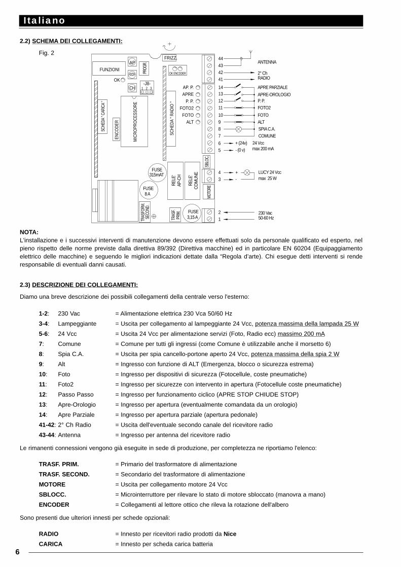
2.2) SCHEMA DEI COLLEGAMENTI:
Fig. 2
NOTA:L'installazione e i successivi interventi di manutenzione devono essere effettuati solo da personale qualificato ed esperto, nelpieno rispetto delle norme previste dalla direttiva 89/392 (Direttiva macchine) ed in particolare EN 60204 (Equipaggiamentoelettrico delle macchine) e seguendo le migliori indicazioni dettate dalla “Regola d’arte). Chi esegue detti interventi si renderesponsabile di eventuali danni causati.
2.3) DESCRIZIONE DEI COLLEGAMENTI:
Diamo una breve descrizione dei possibili collegamenti della centrale verso l'esterno:
1-2: 230 Vac = Alimentazione elettrica 230 Vca 50/60 Hz
3-4: Lampeggiante = Uscita per collegamento al lampeggiante 24 Vcc, potenza massima della lampada 25 W
5-6: 24 Vcc = Uscita 24 Vcc per alimentazione servizi (Foto, Radio ecc) massimo 200 mA
7: Comune = Comune per tutti gli ingressi (come Comune è utilizzabile anche il morsetto 6)
8: Spia C.A. = Uscita per spia cancello-portone aperto 24 Vcc, potenza massima della spia 2 W
9: Alt = Ingresso con funzione di ALT (Emergenza, blocco o sicurezza estrema)
10: Foto = Ingresso per dispositivi di sicurezza (Fotocellule, coste pneumatiche)
11: Foto2 = Ingresso per sicurezze con intervento in apertura (Fotocellule coste pneumatiche)
12: Passo Passo = Ingresso per funzionamento ciclico (APRE STOP CHIUDE STOP)
13: Apre-Orologio = Ingresso per apertura (eventualmente comandata da un orologio)
14: Apre Parziale = Ingresso per apertura parziale (apertura pedonale)
41-42: 2° Ch Radio = Uscita dell'eventuale secondo canale del ricevitore radio
43-44: Antenna = Ingresso per antenna del ricevitore radio
Le rimanenti connessioni vengono già eseguite in sede di produzione, per completezza ne riportiamo l'elenco:
TRASF. PRIM. = Primario del trasformatore di alimentazione
TRASF. SECOND. = Secondario del trasformatore di alimentazione
MOTORE = Uscita per collegamento motore 24 Vcc
SBLOCC. = Microinterruttore per rilevare lo stato di motore sbloccato (manovra a mano)
ENCODER = Collegamenti al lettore ottico che rileva la rotazione dell'albero
Sono presenti due ulteriori innesti per schede opzionali:
RADIO = Innesto per ricevitori radio prodotti da Nice
CARICA = Innesto per scheda carica batteria
Italiano
6
24 Vccmax 200 mA
MIC
ROPR
OCE
SSO
RE
ALT 9
SCHE
DA "
CARI
CA "
SCHE
DA "
RADI
O "
TRAS
FORM
.SE
COND
.
8 AFUSE
ENCO
DER
FUSE315mAT
MOTO
REFUSE3,15 A 1
2
TRAS
F.PR
IM.
REL
E'C
OM
UN
E R
ELE'
AP-C
H3
8
4
SBLO
C.
65
+ (24v)
7
- (0 v)
+-
OK ENCODER
FRIZZ.
OK
31 2-J8-
CH
<<>>
APFUNZIONI PR
OGR.
11
FOTO 10
41
4342
1312
14
44
AP. P.APRE
P. P.FOTO2
ALT
50-60 Hz230 Vac
SPIA C.A.COMUNE
LUCY 24 Vccmax 25 W
FOTO
ANTENNA
2° ChRADIO
FOTO2P. P.APRE-OROLOGIO
APRE PARZIALE
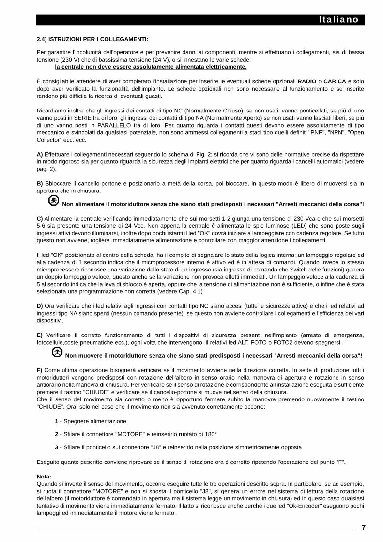
2.4) ISTRUZIONI PER I COLLEGAMENTI:
Per garantire l'incolumità dell'operatore e per prevenire danni ai componenti, mentre si effettuano i collegamenti, sia di bassatensione (230 V) che di bassissima tensione (24 V), o si innestano le varie schede:
la centrale non deve essere assolutamente alimentata elettricamente.
È consigliabile attendere di aver completato l'installazione per inserire le eventuali schede opzionali RADIO o CARICA e solodopo aver verificato la funzionalità dell'impianto. Le schede opzionali non sono necessarie al funzionamento e se inseriterendono più difficile la ricerca di eventuali guasti.
Ricordiamo inoltre che gli ingressi dei contatti di tipo NC (Normalmente Chiuso), se non usati, vanno ponticellati, se piú di unovanno posti in SERIE tra di loro; gli ingressi dei contatti di tipo NA (Normalmente Aperto) se non usati vanno lasciati liberi, se piúdi uno vanno posti in PARALLELO tra di loro. Per quanto riguarda i contatti questi devono essere assolutamente di tipomeccanico e svincolati da qualsiasi potenziale, non sono ammessi collegamenti a stadi tipo quelli definiti "PNP", "NPN", "OpenCollector" ecc. ecc.
A) Effettuare i collegamenti necessari seguendo lo schema di Fig. 2; si ricorda che vi sono delle normative precise da rispettarein modo rigoroso sia per quanto riguarda la sicurezza degli impianti elettrici che per quanto riguarda i cancelli automatici (vederepag. 2).
B) Sbloccare il cancello-portone e posizionarlo a metà della corsa, poi bloccare, in questo modo è libero di muoversi sia inapertura che in chiusura.
Non alimentare il motoriduttore senza che siano stati predisposti i necessari "Arresti meccanici della corsa"!
C) Alimentare la centrale verificando immediatamente che sui morsetti 1-2 giunga una tensione di 230 Vca e che sui morsetti5-6 sia presente una tensione di 24 Vcc. Non appena la centrale è alimentata le spie luminose (LED) che sono poste sugliingressi attivi devono illuminarsi, inoltre dopo pochi istanti il led "OK" dovrà iniziare a lampeggiare con cadenza regolare. Se tuttoquesto non avviene, togliere immediatamente alimentazione e controllare con maggior attenzione i collegamenti.
Il led "OK" posizionato al centro della scheda, ha il compito di segnalare lo stato della logica interna: un lampeggio regolare edalla cadenza di 1 secondo indica che il microprocessore interno è attivo ed è in attesa di comandi. Quando invece lo stessomicroprocessore riconosce una variazione dello stato di un ingresso (sia ingresso di comando che Switch delle funzioni) generaun doppio lampeggio veloce, questo anche se la variazione non provoca effetti immediati. Un lampeggio veloce alla cadenza di5 al secondo indica che la leva di sblocco è aperta, oppure che la tensione di alimentazione non è sufficiente, o infine che è stataselezionata una programmazione non corretta (vedere Cap. 4.1)
D) Ora verificare che i led relativi agli ingressi con contatti tipo NC siano accesi (tutte le sicurezze attive) e che i led relativi adingressi tipo NA siano spenti (nessun comando presente), se questo non avviene controllare i collegamenti e l'efficienza dei varidispositivi.
E) Verificare il corretto funzionamento di tutti i dispositivi di sicurezza presenti nell'impianto (arresto di emergenza,fotocellule,coste pneumatiche ecc.), ogni volta che intervengono, il relativi led ALT, FOTO o FOTO2 devono spegnersi.
Non muovere il motoriduttore senza che siano stati predisposti i necessari "Arresti meccanici della corsa"!
F) Come ultima operazione bisognerà verificare se il movimento avviene nella direzione corretta. In sede di produzione tutti imotoriduttori vengono predisposti con rotazione dell'albero in senso orario nella manovra di apertura e rotazione in sensoantiorario nella manovra di chiusura. Per verificare se il senso di rotazione è corrispondente all'installazione eseguita è sufficientepremere il tastino "CHIUDE" e verificare se il cancello-portone si muove nel senso della chiusura.Che il senso del movimento sia corretto o meno è opportuno fermare subito la manovra premendo nuovamente il tastino"CHIUDE". Ora, solo nel caso che il movimento non sia avvenuto correttamente occorre:
1 - Spegnere alimentazione
2 - Sfilare il connettore "MOTORE" e reinserirlo ruotato di 180°
3 - Sfilare il ponticello sul connettore "J8" e reinserirlo nella posizione simmetricamente opposta
Eseguito quanto descritto conviene riprovare se il senso di rotazione ora è corretto ripetendo l'operazione del punto "F".
Nota:Quando si inverte il senso del movimento, occorre eseguire tutte le tre operazioni descritte sopra. In particolare, se ad esempio,si ruota il connettore "MOTORE" e non si sposta il ponticello "J8", si genera un errore nel sistema di lettura della rotazionedell'albero (il motoriduttore è comandato in apertura ma il sistema legge un movimento in chiusura) ed in questo caso qualsiasitentativo di movimento viene immediatamente fermato. Il fatto si riconosce anche perchè i due led "Ok-Encoder" eseguono pochilampeggi ed immediatamente il motore viene fermato.
Italiano
7
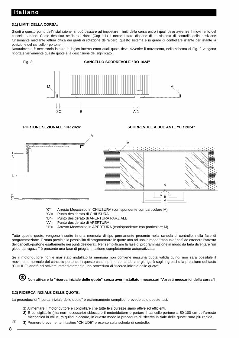
3.1) LIMITI DELLA CORSA:
Giunti a questo punto dell'installazione, si può passare ad impostare i limiti della corsa entro i quali deve avvenire il movimento delcancello-portone. Come descritto nell'introduzione (Cap 1.1) il motoriduttore dispone di un sistema di controllo della posizionefunzionante mediante lettura ottica dei gradi di rotazione dell'albero, questo sistema è in grado di controllare istante per istante laposizione del cancello - portone.Naturalmente è necessario istruire la logica interna entro quali quote deve avvenire il movimento, nello schema di Fig. 3 vengonoriportate visivamente queste quote e la descrizione del significato.
Fig. 3 CANCELLO SCORREVOLE “RO 1024”
PORTONE SEZIONALE “CR 2024” SCORREVOLE A DUE ANTE “CR 2024”
"0"= Arresto Meccanico in CHIUSURA (corrispondente con particolare M)"C"= Punto desiderato di CHIUSURA"B"= Punto desiderato di APERTURA PARZIALE"A"= Punto desiderato di APERTURA"1"= Arresto Meccanico in APERTURA (corrispondente con particolare M)
Tutte queste quote, vengono inserite in una memoria di tipo permanente presente nella scheda di controllo, nella fase diprogrammazione. È stata prevista la possibilità di programmare le quote una ad una in modo "manuale" così da ottenere l'arrestodel cancello-portone esattamente nei punti desiderati. Per semplificare la fase di programmazione in modo da farla diventare "ungioco da ragazzi" è presente una fase di programmazione completamente automatizzata.
Se il motoriduttore non è mai stato installato la memoria non contiene nessuna quota valida quindi non sarà possibile ilmovimento normale del cancello-portone, in questo caso il primo comando che giungerà sugli ingressi o la pressione del tasto"CHIUDE" andrà ad attivare immediatamente una procedura di "ricerca iniziale delle quote".
Non attivare la "ricerca iniziale delle quote" senza aver installato i necessari "Arresti meccanici della corsa"!
3.2) RICERCA INIZIALE DELLE QUOTE:
La procedura di "ricerca iniziale delle quote" è estremamente semplice, prevede solo queste fasi:
1) Alimentare il motoriduttore e controllare che tutte le sicurezze siano attive ed efficienti.2) È consigliabile (ma non necessario) sbloccare il motoriduttore e portare il cancello-portone a 50-100 cm dell'arresto
meccanico in chiusura quindi bloccare, in questo modo la procedura di "ricerca iniziale delle quote" sarà più rapida.
3) Premere brevemente il tastino "CHIUDE" presente sulla scheda di controllo.
Italiano
8
MM
0 C B A 1
M
M
1A
B
C 0
C C
0
BA1
Ora il motoriduttore muoverà lentamente il cancello nel senso della chiusura fino a rilevare il punto "0" (l'arresto meccanico che delimita ilpunto di massima chiusura). Una volta raggiunto il punto "0" il cancello si arresta e questo provoca l'intervento del sistema di frizioneintelligente (vedi Cap. 1.3) quindi la quota rilevata dall'encoder verrà utilizzata per azzerare il contatore della quota. Subito dopo ilmotoriduttore muoverà lentamente il cancello nel senso dell'apertura fino a rilevare il punto "1" (l'altro arresto meccanico che delimita il puntodi massima apertura); anche questa volta, raggiunto il punto "1", il cancello si arresta e la quota viene memorizzata.
Con queste due operazioni sono stati rilevati i limiti massimi della corsa, con una operazione matematica viene calcolato il punto“C” che viene posto nel caso dell’utilizzo come RO1024 (con switch 10 in posizione OFF) a 5 centrimetri dal punto “0’’, mentrenel caso di utilizzo come CR2024 (con lo switch 10 in posizione ON) a qualche millimetro dal punto “0”.Il punto “A” viene posto pochi centimetri prima del punto “1”ed infine il punto “B” viene posto nel caso del CR2024 a metà tra ipunti “0” e “1”, mentre nel caso del RO1024 a 1 metro dal punto “C”
4) la procedura di "ricerca iniziale" delle quote è conclusa. Impostare i dip switch delle funzioni nel modo desideratoed il motoriduttore è pronto all'uso.
La procedura descritta esegue autonomamente la memorizzazione delle quote appena rilevate, pertanto non serve fare nessunaaltra operazione.
Se durante la “ricerca iniziale delle quote” avviene un evento esterno (altra pressione su un tastino, intervento di Foto o impulsodi Passo P.) il movimento al cancello - portone verrà immediatamente arrestato, quindi sarà necessario ripetere l’operazione dalpunto (3).Dopo una ricerca iniziale, se si desidera si puo’ modificare attraverso la ricerca manuale, una o piu’ delle quote rilevate (esclusala quota 0)
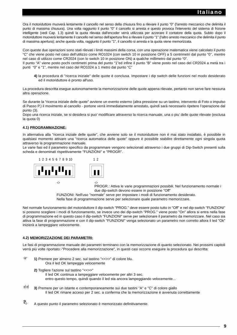
4.1) PROGRAMMAZIONE:
In alternativa alla "ricerca iniziale delle quote", che avviene solo se il motoriduttore non è mai stato installato, è possibile inqualsiasi momento attivare una "ricerca automatica delle quote" oppure è possibile stabilire direttamente ogni singola quotaattraverso la programmazione manuale.Le varie fasi ed il parametro specifico da programmare vengono selezionati attraverso i due gruppi di Dip-Switch presenti sullascheda e denominati rispettivamente "FUNZIONI" e "PROGR".
a aPROGR.: Attiva le varie programmazioni possibili. Nel funzionamento normale i due dip-switch devono essere in posizione "Off"
FUNZIONI: Nell'uso "normale" serve per impostare i modi di funzionamento desiderato.Nella fase di programmazione serve per selezionare quale parametro memorizzare.
Nel normale funzionamento del motoriduttore il dip-switch "PROG." deve essere posto tutto in "Off" e nel dip-switch "FUNZIONI"si possono scegliere i modi di funzionamento, se invece uno dei dip-switch "PROG." viene posto "On" allora si entra nella fasedi programmazione ed in questo caso il dip-switch "FUNZIONI" serve per selezionare il parametro da memorizzare. Nel caso siaattiva la fase di programmazione e con il dip-switch "FUNZIONI" venga selezionato un parametro non corretto allora il led "Ok"inizierà a lampeggiare velocemente.
4.2) MEMORIZZAZIONE DEI PARAMETRI:
Le fasi di programmazione manuale dei parametri terminano con la memorizzazione di quanto selezionato. Nei prossimi capitoliverrà più volte riportato:-"Procedere alla memorizzazione", in questi casi occorre eseguire la procedura qui descritta:
1) Premere per almeno 2 sec. sul tastino "<<>>" di colore blu. Ora il led OK lampeggia velocemente
2) Togliere l'azione sul tastino "<<>>"Il led OK continua a lampeggiare velocemente per altri 3 sec.entro questo tempo, quindi quando il led sta ancora lampeggiando velocemente...
3) Premere per un istante e contemporaneamente sui due tastini "A" e "C" di colore gialloIl led OK rimane acceso per 2 sec. a conferma che la memorizzazione è avvenuta correttamente
A questo punto il parametro selezionato è memorizzato definitivamente.
Italiano
9
1 2 3 4 5 6 7 8 9 10 1 2
4.3) PROGRAMMAZIONE MANUALE DELLE QUOTE:
Tutte le quote descritte nel precedente capitolo possono essere programmate in modo manuale, vediamo ora in che modoquesto sia possibile:
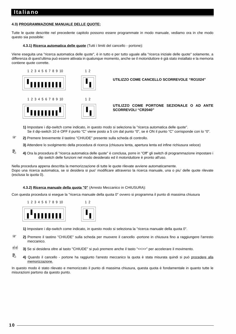
4.3.1) Ricerca automatica delle quote (Tutti i limiti del cancello - portone):
Viene eseguita una "ricerca automatica delle quote", è in tutto e per tutto uguale alla "ricerca iniziale delle quote" solamente, adifferenza di quest'ultima può essere attivata in qualunque momento, anche se il motoriduttore è già stato installato e la memoriacontiene quote corrette.
1) Impostare i dip-switch come indicato, in questo modo si seleziona la "ricerca automatica delle quote".Se il dip-switch 10 è OFF il punto “C” viene posto a 5 cm dal punto “0”, se è ON il punto “C” corrisponde con lo “0”.
2) Premere brevemente il tastino "CHIUDE" presente sulla scheda di controllo.
3) Attendere lo svolgimento della procedura di ricerca (chiusura lenta, apertura lenta ed infine richiusura veloce)
4) Ora la procedura di "ricerca automatica delle quote" è conclusa, porre in "Off" gli switch di programmazione impostare idip switch delle funzioni nel modo desiderato ed il motoriduttore è pronto all'uso.
Nella procedura appena descritta la memorizzazione di tutte le quote rilevate avviene automaticamente.Dopo una ricerca automatica, se si desidera si puo’ modificare attraverso la ricerca manuale, una o piu’ delle quote rilevate(esclusa la quota 0).
4.3.2) Ricerca manuale della quota "0" (Arresto Meccanico in CHIUSURA):
Con questa procedura si esegue la "ricerca manuale della quota 0" ovvero si programma il punto di massima chiusura
1) Impostare i dip-switch come indicato, in questo modo si seleziona la "ricerca manuale della quota 0".
2) Premere il tastino "CHIUDE" sulla scheda per muovere il cancello -portone in chiusura fino a raggiungere l'arrestomeccanico.
3) Se si desidera oltre al tasto "CHIUDE" si può premere anche il tasto "<<>>" per accelerare il movimento.
4) Quando il cancello - portone ha raggiunto l'arresto meccanico la quota è stata misurata quindi si può procedere allamemorizzazione.
In questo modo è stato rilevato e memorizzato il punto di massima chiusura, questa quota è fondamentale in quanto tutte lemisurazioni partono da questo punto.
Italiano
10
1 2 3 4 5 6 7 8 9 10 1 2
1 2 3 4 5 6 7 8 9 10 1 2
UTILIZZO COME CANCELLO SCORREVOLE “RO1024”
UTILIZZO COME PORTONE SEZIONALE O AD ANTESCORREVOLI “CR2040”
1 2 3 4 5 6 7 8 9 10 1 2
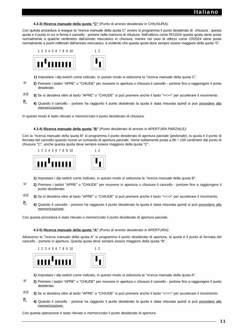
4.3.3) Ricerca manuale della quota "C" (Punto di arresto desiderato in CHIUSURA):
Con questa procedura si esegue la “ricerca manuale della quota C” ovvero si programma il punto desiderato di chiusura ; questaquota e il punto in cui si ferma il cancello - portone nella manovra di chiusura. Nell’utilizzo come RO1024 questa quota viene postanormalmente a qualche centimetro dall’arresto meccanico in chiusura, mentre nel caso di utilizzo come CR2024 viene postanormalmente a pochi millimetri dall’arresto meccanico, è evidente che questa quota deve sempre essere maggiore della quota “0”.
1) Impostare i dip-switch come indicato, in questo modo si seleziona la "ricerca manuale della quota C".
2) Premere i tastini "APRE" o "CHIUDE" per muovere in apertura o chiusura il cancello - portone fino a raggiungere il puntodesiderato.
3) Se si desidera oltre al tasto "APRE" o "CHIUDE" si può premere anche il tasto "<<>>" per accelerare il movimento.
4) Quando il cancello - portone ha raggiunto il punto desiderato la quota è stata misurata quindi si può procedere allamemorizzazione.
In questo modo è stato rilevato e memorizzato il punto desiderato di chiusura.
4.3.4) Ricerca manuale della quota "B" (Punto desiderato di arresto in APERTURA PARZIALE):
Con la "ricerca manuale della quota B" si programma il punto desiderato di apertura parziale (pedonale); la quota è il punto difermata del cancello quando riceve un comando di apertura parziale. Viene solitamente posta a 80 ÷ 100 centimetri dal punto dichiusura "C", anche questa quota deve sempre essere maggiore della quota "C".
1) Impostare i dip-switch come indicato, in questo modo si seleziona la "ricerca manuale della quota B".
2) Premere i tastini "APRE" o "CHIUDE" per muovere in apertura o chiusura il cancello - portone fino a raggiungere ilpunto desiderato.
3) Se si desidera oltre al tasto "APRE" o "CHIUDE" si può premere anche il tasto "<<>>" per accelerare il movimento.
4) Quando il cancello - portone ha raggiunto il punto desiderato la quota è stata misurata quindi si può procedere allamemorizzazione.
Con questa procedura è stato rilevato e memorizzato il punto desiderato di apertura parziale.
4.3.5) Ricerca manuale della quota "A" (Punto di arresto desiderato in APERTURA):
Attraverso la "ricerca manuale della quota A" si programma il punto desiderato di apertura; la quota è il punto di fermata delcancello - portone in apertura. Questa quota deve sempre essere maggiore della quota "B".
1) Impostare i dip-switch come indicato, in questo modo si seleziona la "ricerca manuale della quota A".
2) Premere i tastini "APRE" o "CHIUDE" per muovere in apertura o chiusura il cancello - portone fino a raggiungere il puntodesiderato.
3) Se si desidera oltre al tasto "APRE" o "CHIUDE" si può premere anche il tasto "<<>>" per accelerare il movimento.
4) Quando il cancello - portone ha raggiunto il punto desiderato la quota è stata misurata quindi si può procedere allamemorizzazione.
Con questa operazione è stato rilevato e memorizzato il punto desiderato di apertura.
Italiano
11
1 2 3 4 5 6 7 8 9 10 1 2
1 2 3 4 5 6 7 8 9 10 1 2
1 2 3 4 5 6 7 8 9 10 1 2
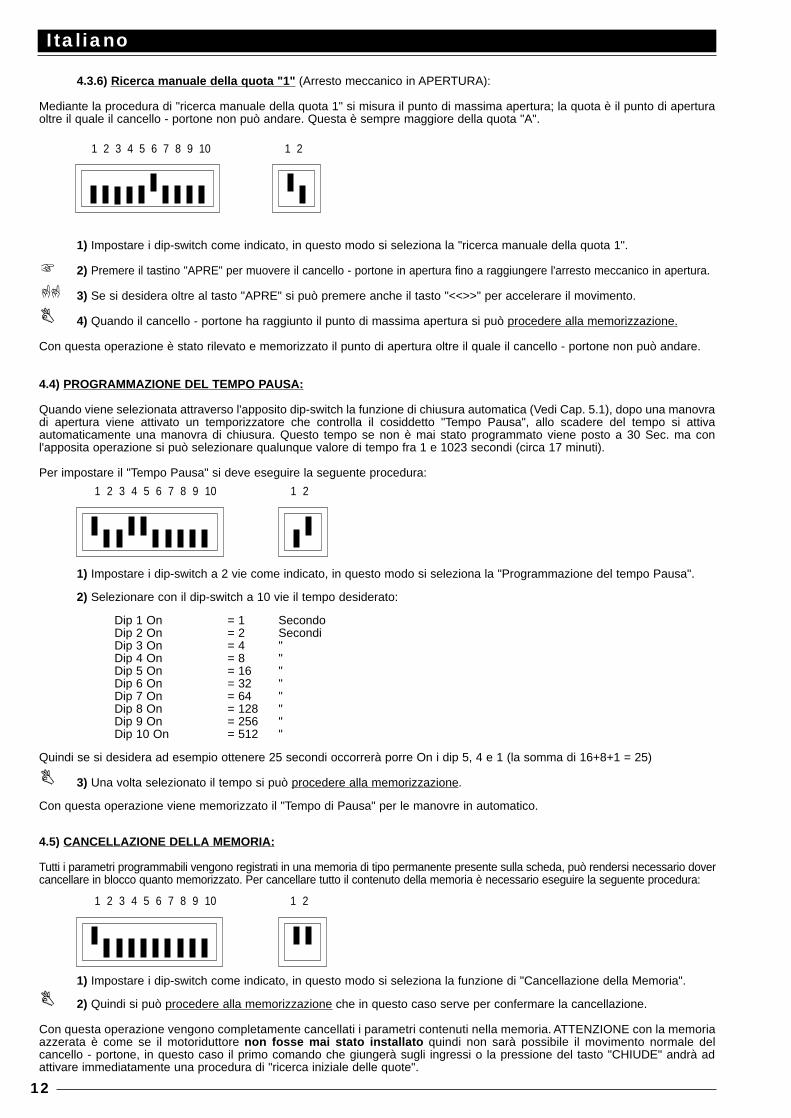
4.3.6) Ricerca manuale della quota "1" (Arresto meccanico in APERTURA):
Mediante la procedura di "ricerca manuale della quota 1" si misura il punto di massima apertura; la quota è il punto di aperturaoltre il quale il cancello - portone non può andare. Questa è sempre maggiore della quota "A".
1) Impostare i dip-switch come indicato, in questo modo si seleziona la "ricerca manuale della quota 1".
2) Premere il tastino "APRE" per muovere il cancello - portone in apertura fino a raggiungere l'arresto meccanico in apertura.
3) Se si desidera oltre al tasto "APRE" si può premere anche il tasto "<<>>" per accelerare il movimento.
4) Quando il cancello - portone ha raggiunto il punto di massima apertura si può procedere alla memorizzazione.
Con questa operazione è stato rilevato e memorizzato il punto di apertura oltre il quale il cancello - portone non può andare.
4.4) PROGRAMMAZIONE DEL TEMPO PAUSA:
Quando viene selezionata attraverso l'apposito dip-switch la funzione di chiusura automatica (Vedi Cap. 5.1), dopo una manovradi apertura viene attivato un temporizzatore che controlla il cosiddetto "Tempo Pausa", allo scadere del tempo si attivaautomaticamente una manovra di chiusura. Questo tempo se non è mai stato programmato viene posto a 30 Sec. ma conl'apposita operazione si può selezionare qualunque valore di tempo fra 1 e 1023 secondi (circa 17 minuti).
Per impostare il "Tempo Pausa" si deve eseguire la seguente procedura:
1) Impostare i dip-switch a 2 vie come indicato, in questo modo si seleziona la "Programmazione del tempo Pausa".
2) Selezionare con il dip-switch a 10 vie il tempo desiderato:
Dip 1 On = 1 SecondoDip 2 On = 2 SecondiDip 3 On = 4 "Dip 4 On = 8 "Dip 5 On = 16 "Dip 6 On = 32 "Dip 7 On = 64 "Dip 8 On = 128 "Dip 9 On = 256 "Dip 10 On = 512 "
Quindi se si desidera ad esempio ottenere 25 secondi occorrerà porre On i dip 5, 4 e 1 (la somma di 16+8+1 = 25)
3) Una volta selezionato il tempo si può procedere alla memorizzazione.
Con questa operazione viene memorizzato il "Tempo di Pausa" per le manovre in automatico.
4.5) CANCELLAZIONE DELLA MEMORIA:
Tutti i parametri programmabili vengono registrati in una memoria di tipo permanente presente sulla scheda, può rendersi necessario dovercancellare in blocco quanto memorizzato. Per cancellare tutto il contenuto della memoria è necessario eseguire la seguente procedura:
1) Impostare i dip-switch come indicato, in questo modo si seleziona la funzione di "Cancellazione della Memoria".
2) Quindi si può procedere alla memorizzazione che in questo caso serve per confermare la cancellazione.
Con questa operazione vengono completamente cancellati i parametri contenuti nella memoria. ATTENZIONE con la memoriaazzerata è come se il motoriduttore non fosse mai stato installato quindi non sarà possibile il movimento normale delcancello - portone, in questo caso il primo comando che giungerà sugli ingressi o la pressione del tasto "CHIUDE" andrà adattivare immediatamente una procedura di "ricerca iniziale delle quote".
Italiano
12
1 2 3 4 5 6 7 8 9 10 1 2
1 2 3 4 5 6 7 8 9 10 1 2
1 2 3 4 5 6 7 8 9 10 1 2
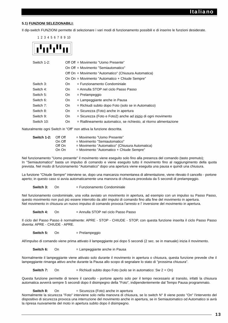
5.1) FUNZIONI SELEZIONABILI:
Il dip-switch FUNZIONI permette di selezionare i vari modi di funzionamento possibili e di inserire le funzioni desiderate.
Switch 1-2: Off Off = Movimento "Uomo Presente”
On Off = Movimento "Semiautomatico"
Off On = Movimento "Automatico" (Chiusura Automatica)
On On = Movimento "Automatico + Chiude Sempre"
Switch 3: On = Funzionamento Condominiale
Switch 4: On = Annulla STOP nel ciclo Passo Passo
Switch 5: On = Prelampeggio
Switch 6: On = Lampeggiante anche in Pausa
Switch 7: On = Richiudi subito dopo Foto (solo se in Automatico)
Switch 8: On = Sicurezza (Foto) anche in apertura
Switch 9: On = Sicurezza (Foto e Foto2) anche ad inizio di ogni movimento
Switch 10: On = Riallineamento automatico, se richiesto, al ritorno alimentazione
Naturalmente ogni Switch in "Off" non attiva la funzione descritta.
Switch 1-2: Off Off = Movimento "Uomo Presente”On Off = Movimento "Semiautomatico"Off On = Movimento "Automatico" (Chiusura Automatica)On On = Movimento "Automatico + Chiude Sempre"
Nel funzionamento "Uomo presente" il movimento viene eseguito solo fino alla presenza del comando (tasto premuto);In "Semiautomatico" basta un impulso di comando e viene eseguito tutto il movimento fino al raggiungimento della quotaprevista. Nel modo di funzionamento "Automatico" dopo una apertura viene eseguita una pausa e quindi una chiusura.
La funzione "Chiude Sempre" interviene se, dopo una mancanza momentanea di alimentazione, viene rilevato il cancello - portoneaperto; in questo caso si avvia automaticamente una manovra di chiusura preceduta da 5 secondi di prelampeggio.
Switch 3: On = Funzionamento Condominiale
Nel funzionamento condominiale, una volta avviato un movimento in apertura, ad esempio con un impulso su Passo Passo,questo movimento non puó piú essere interrotto da altri impulsi di comando fino alla fine del movimento in apertura.Nel movimento in chiusura un nuovo impulso di comando provoca l'arresto e l' inversione del movimento in apertura.
Switch 4: On = Annulla STOP nel ciclo Passo Passo
Il ciclo del Passo Passo è normalmente: APRE - STOP - CHIUDE - STOP, con questa funzione inserita il ciclo Passo Passodiventa: APRE - CHIUDE - APRE.
Switch 5: On = Prelampeggio
All'impulso di comando viene prima attivato il lampeggiante poi dopo 5 secondi (2 sec. se in manuale) inizia il movimento.
Switch 6: On = Lampeggiante anche in Pausa
Normalmente il lampeggiante viene attivato solo durante il movimento in apertura o chiusura, questa funzione prevede che illampeggiante rimanga attivo anche durante la Pausa allo scopo di segnalare lo stato di "prossima chiusura".
Switch 7: On = Richiudi subito dopo Foto (solo se in automatico: Sw 2 = On)
Questa funzione permette di tenere il cancello - portone aperto solo per il tempo necessario al transito, infatti la chiusuraautomatica avverrà sempre 5 secondi dopo il disimpegno della "Foto", indipendentemente dal Tempo Pausa programmato.
Switch 8: On = Sicurezza (Foto) anche in aperturaNormalmente la sicurezza "Foto" interviene solo nella manovra di chiusura, se lo switch N° 8 viene posto "On" l'intervento deldispositivo di sicurezza provoca una interruzione del movimento anche in apertura, se in Semiautomatico od Automatico si avràla ripresa nuovamente del moto in apertura subito dopo il disimpegno.
Italiano
13
1 2 3 4 5 6 7 8 9 10
Switch 9: On = Sicurezze (Foto e Foto2) anche ad inizio di ogni movimento
É solito che la sicurezza "Foto" intervenga solo durante la manovra di chiusura e che "Foto2" intervenga solo durante la manovradi apertura . Se si desidera aumentare il livello di sicurezza e possibile, prima di iniziare il movimento, verificare il consenso dallesicurezze "Foto" e "Foto2" quindi solo dopo iniziare il movimento.
Switch 10: On = Riallineamento automatico, se richiesto, al ritorno alimentazione
Quando manca l'alimentazione elettrica ed il cancello - portone viene sbloccato, il sistema di lettura della posizione del cancello-portone perde la quota; per questa evenienza è stata prevista una procedura di "Riallineamento" che consiste nel ricercarenuovamente il punto "C". La procedura di riallineamento viene eseguita normalmente, dopo il ritorno dell'alimentazione elettrica,quando giunge il primo impulso di comando. Con il dip-switch N° 10 in "On" il riallineamento avviene non appena ritornaalimentazione e senza attendere impulsi di comando.
6.1) PROVA DEL FUNZIONAMENTO:
Verificati i collegamenti (Cap. 2.4), eseguita la fase di programmazione dei limiti della corsa (Cap. 3.2 o 4.3.1) èpossibile provare il movimento dell'attuatore, si consiglia di operare in modo uomo presente con tutte le funzionidisattivate (tutti gli Switch Off); per ogni eventualità, in modo uomo presente, rilasciando il tasto di comando si ottienel'immediato arresto del motore. Se si usa come comando l'ingresso Passo P. il primo movimento (dopo l'accensione)dovrà essere in apertura.
In questa fase risulta particolarmente comodo utilizzare i tastini "AP","CH" presenti direttamente sulla scheda. Agendosugli ingressi di comando movimentare il cancello - portone fino al punto desiderato di apertura "A", circa 20 cm primadel punto di fermata deve intervenire la fase di "rallentamento" che permette di raggiungere il punto previsto con unavelocità ridotta a circa il 30 %. Eseguire poi un movimento in chiusura fino al raggiungimento del punto desiderato dichiusura "C", anche in questo caso dovrà intervenire la fase di rallentamento 20 cm prima dell'arresto del movimento.Passare ora a provare l'intervento dei dispositivi di sicurezza, FOTO in apertura non ha alcun effetto, in chiusuraprovoca la fermata del movimento; FOTO 2 in chiusura non ha alcun effetto, in apertura provoca la fermata delmovimento. I dispositivi collegati nell'ingresso ALT agiscono sia in apertura che in chiusura provocando sempre lafermata del movimento.
Le recenti normative europee, prEN 12453: sicurezza nell’impiego delle porte motorizzate - requisiti e classificazioni; prEN12445: sicurezza nell’impiego delle porte motorizzate - metodi di prova; (non ancora approvate in modo definitivo, ma lo sarannonel corso del 1998) richiedono l’utilizzo di misure al fine di limitare le forze in gioco nel movimento delle porte automatiche paria un massimo di 1400N come forza di impatto; una forza residua statica massima di 150N che deve poi annullarsi entro 5secondi dall’impatto.Questo si ottiene mediante la regolazione della frizione elettronica intelligente. Sulla scheda è presente il trimmer FRIZZ. chepermette di stabilire la soglia di intervento della frizione. Come descritto nel Cap. 1.3 il sistema di frizione intelligente opera dei calcoli al fine di ottenere la velocità media del movimentoe quindi intervenire con maggiore precisione, per valutare l’effetto della regolazione sul trimmer conviene quindi attendere che ilmovimento sia avviato e che il cancello - portone abbia raggiunto la velocità standard. Attenzione anche al fatto che, sempre perquestioni di sicurezza, se la frizione interviene per tre volte consecutive il movimento viene fermato senza eseguire l’inversione.
Se viene selezionato il modo di funzionamento in automatico al termine della manovra di apertura si esegue una "pausa"al termine della quale viene lanciata automaticamente una manovra di chiusura. Il tempo di pausa se non programmatocon l'apposita procedura, è pari a 30 secondi. La pausa viene attivata anche nel movimento in semiautomatico quando, in chiusura, l'intervento di un dispositivo disicurezza o della frizione intelligente provoca una inversione in apertura .
Solo ora, al termine di tutte le regolazioni e senza l'alimentazione elettrica consigliamo di inserire il ricevitore radio.
6.2) DESCRIZIONE DEI MODI DI FUNZIONAMENTO:
Nel funzionamento in modo uomo presente, l'ingresso APRE-OROLOGIO consente il movimento fino al punto desiderato diapertura, l'ingresso APRE PAR. consente il movimento fino al punto di apertura parziale, il PASSO P. consente il movimentoalternativamente in apertura e in chiusura; non appena cessa il comando in ingresso il movimento si arresta. In apertura ilmovimento si arresta nel punto previsto oppure se manca il consenso dalla FOTO 2; in chiusura invece il movimento si arrestaanche se manca il consenso dalla FOTO. Un intervento su ALT provoca un immediato arresto del movimento, questo sia inapertura che in chiusura. Una volta che il movimento si è arrestato è necessario cessare il comando in ingresso prima di poteriniziare un nuovo movimento.
Nel funzionamento in uno dei modi automatici (semiautomatico - automatico e chiude sempre) un comando sull'ingresso APRE-OROLOGIO provoca il movimento in apertura, se il comando permane una volta raggiunta l'apertura il movimento rimane"congelato" in una pausa infinita; solo quando cessa il comando il cancello - portone si potrà essere richiuso. Gli impulsi dicomando sull'ingresso APRE PAR. provocano l'apertura solo fino al punto di apertura parziale. Un impulso su PASSO P. provocaalternativamente apertura o chiusura. Un secondo impulso sul PASSO P. o sullo stesso ingresso che ha iniziato il movimentoprovoca uno Stop.
Italiano
14
Sia in apertura che in chiusura un intervento su ALT provoca un immediato arresto del movimento.Se in un ingresso di comando invece di un impulso viene mantenuto un segnale continuo si provoca uno stato di "prevalenza"in cui gli altri ingressi di comando rimangono disabilitati (utile per collegare un orologio o un selettore Notte-Giorno).
Nel caso fosse inserito il modo di funzionamento automatico, dopo una manovra di apertura, viene eseguita una pausa al termineviene eseguita una chiusura. Se durante la pausa vi fosse un intervento di FOTO, il temporizzatore verrà ripristinato con unnuovo tempo; se invece durante la pausa si interviene su ALT la funzione di richiusura viene cancellata e si passa in uno statodi STOP.
In apertura l'intervento della FOTO non ha effetto mentre la FOTO 2 provoca l'inversione del moto; in chiusura l'intervento dallaFOTO provoca una inversione del moto quindi una nuova pausa, infine una richiusura.
7.1) SCHEDA "CARICA" per alimentazione anche da batteria
Il motoriduttore dispone di in trasformatore di potenza adeguata a supportare la richiesta di energia del motore e della schedaelettronica tale da rendere il tutto alimentabile direttamente da rete. Nel caso si desideri il funzionamento del sistema anche quando viene a mancare l'energia elettrica da rete è necessarioaggiungere una idonea batteria e la relativa scheda caricabatteria. La batteria, visto le rilevanti dimensioni, deve essere posta esternamente al motoriduttore e collegata su due appositi morsettidella scheda caricabatteria, mentre quest'ultima va innestata nell'apposito connettore sulla centrale.
8) MANUTENZIONE:
La scheda come parte elettronica, non necessita di alcuna manutenzione particolare. Verificare comunque periodicamente,almeno due volte all’anno, la perfetta efficienza e la regolazione del dispositivo di controllo della forza massima del motore,eventualmente agire sul trimmer di regolazione..Controllare la corretta efficienza dei dispositivi di sicurezza (fotocellule, coste pneumatiche, ecc.) ed il corretto funzionamentodel lampeggiante.
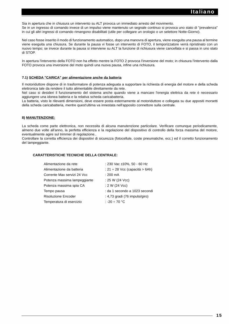
CARATTERISTICHE TECNICHE DELLA CENTRALE:
Alimentazione da rete : 230 Vac ±10%, 50 - 60 Hz
Alimentazione da batteria : 21 ÷ 28 Vcc (capacità > 6Ah)
Corrente Max servizi 24 Vcc : 200 mA
Potenza massima lampeggiante : 25 W (24 Vcc)
Potenza massima spia CA : 2 W (24 Vcc)
Tempo pausa : da 1 secondo a 1023 secondi
Risoluzione Encoder : 4,73 gradi (76 impulsi/giro)
Temperatura di esercizio : -20 ÷ 70 °C
Italiano
15

Italiano
16
English
17
This manual is for use only by technical personnel qualified to carry out the installation.No information given in this manual can be considered of any interest to the end user!
INDEX:
Quick guide : 18Introduction : 19
Description of the product : 19Installation instructions : 20
Wiring diagram : 21Description of connections : 21Connection instructions : 22
Travel limits : 23Automatic limit search : 23
Programming : 24Storing parameters : 24Manual programming of limits : 25Programming pause time : 27Cancelling the memory : 27
Setting mode function switches : 28Testing the unit : 29Description of functioning modes : 29“CHARGE” card for battery powering : 30Maintenance : 30Technical data : 30
IMPORTANT NOTICE:
It is our duty to remind you that you are carrying out operations on machine systems classified in the “Automatic gates and doors”category and as such are considered particularly “hazardous”. It is your job to make them as “Safe” as is reasonably possible!
Only qualified personnel should install and service the equipment. It is the responsibility of the installer to ensure that theequipment is correctly and professionally installed in compliance with all relevant regulations and standards applicable in thecountry of installation.We draw your attention to the following most important European directives - it is the installers responsibility to check what otherregulations apply in the country of installation.
EEC 89/392 (Machine Directive) EEC 89/336 (EMC Directive) EEC 73/23 (Low Voltage Directive) PrEN 12453 (Safety in using motorised doors - requirements and classifications)PrEN 12445 (Safety in using motorised doors - testing methods)
Nice products are designed and manufactured to meet all current European standards and it is essential that the installer alsoinstalls the equipment in accordance with all local and European requirements.
Unqualified personnel or those who do not know the standards applicable to the “Automatic gates and doors” category:Must under no circumstances attempt to install or service the equipment
Personnel who install or service the equipment without observing all the applicable standards:Will be held responsible for any damage the system may cause!
QUICK GUIDE: Do not install the motor without the “Mechanical travel stop devices”!
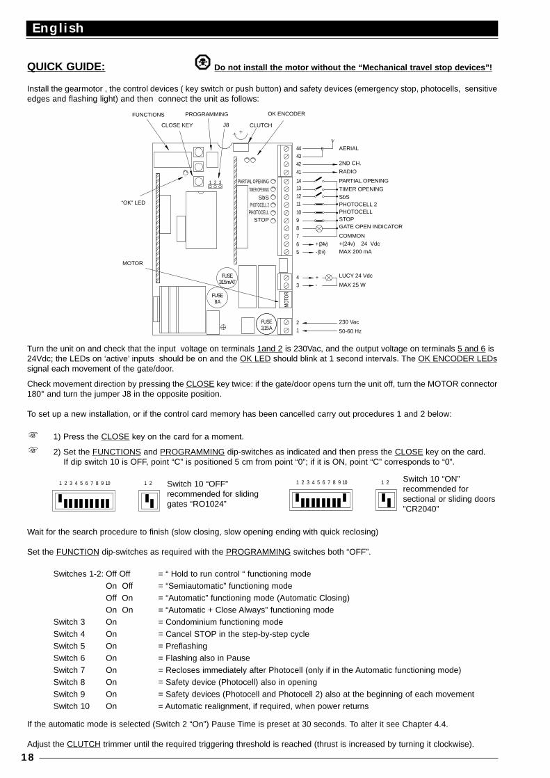
Install the gearmotor , the control devices ( key switch or push button) and safety devices (emergency stop, photocells, sensitiveedges and flashing light) and then connect the unit as follows:
Turn the unit on and check that the input voltage on terminals 1and 2 is 230Vac, and the output voltage on terminals 5 and 6 is24Vdc; the LEDs on ‘active’ inputs should be on and the OK LED should blink at 1 second intervals. The OK ENCODER LEDssignal each movement of the gate/door.
Check movement direction by pressing the CLOSE key twice: if the gate/door opens turn the unit off, turn the MOTOR connector180° and turn the jumper J8 in the opposite position.
To set up a new installation, or if the control card memory has been cancelled carry out procedures 1 and 2 below:
1) Press the CLOSE key on the card for a moment.
2) Set the FUNCTIONS and PROGRAMMING dip-switches as indicated and then press the CLOSE key on the card.If dip switch 10 is OFF, point “C” is positioned 5 cm from point “0”; if it is ON, point “C” corresponds to “0”.
Wait for the search procedure to finish (slow closing, slow opening ending with quick reclosing)
Set the FUNCTION dip-switches as required with the PROGRAMMING switches both “OFF”.
Switches 1-2: Off Off = “ Hold to run control “ functioning modeOn Off = “Semiautomatic” functioning modeOff On = “Automatic” functioning mode (Automatic Closing)On On = “Automatic + Close Always” functioning mode
Switch 3 On = Condominium functioning modeSwitch 4 On = Cancel STOP in the step-by-step cycle Switch 5 On = PreflashingSwitch 6 On = Flashing also in PauseSwitch 7 On = Recloses immediately after Photocell (only if in the Automatic functioning mode)Switch 8 On = Safety device (Photocell) also in openingSwitch 9 On = Safety devices (Photocell and Photocell 2) also at the beginning of each movementSwitch 10 On = Automatic realignment, if required, when power returns
If the automatic mode is selected (Switch 2 “On”) Pause Time is preset at 30 seconds. To alter it see Chapter 4.4.
Adjust the CLUTCH trimmer until the required triggering threshold is reached (thrust is increased by turning it clockwise).
English
18
- (0 v)
MOTOR
8 A
315mAT
FUSE
FUSE
1
MO
TOR
FUSE3,15 A
2
34 +
-
“OK” LED
FUNCTIONS
31 2
J8
PROGRAMMING
CLOSE KEY
98
65
+ (24v)
7
11
10
1312
14
41
4342
44
CLUTCH
OK ENCODER
AERIAL
2ND CH.
RADIO
PARTIAL OPENING
TIMER OPENING SbS PHOTOCELL 2 PHOTOCELL STOP GATE OPEN INDICATOR
COMMON +(24v) 24 Vdc MAX 200 mA
LUCY 24 Vdc
MAX 25 W
230 Vac
50-60 Hz
PARTIAL OPENING
TIMER OPENING SbS
PHOTOCELL 2 PHOTOCELL
STOP
1 2 3 4 5 6 7 8 9 10 1 2 1 2 3 4 5 6 7 8 9 10 1 2Switch 10 “OFF”recommended for slidinggates “RO1024”
Switch 10 “ON”recommended forsectional or sliding doors”CR2040”
1.1) INTRODUCTION:
The electronic card is designed to control either the “RO1024” ROBO PLUS actuator model or the “CR2024” CLIMBERactuator model which both have a 24 V dc motor. This is a state-of-the-art product: in place of the traditional limit switches, theactuators have an optical position control system that reads the shaft’s rotation degrees (ENCODER). This provides the systemwith the facility for more functions than traditional control methods do. The stop point is reached by slowing down and coming toa halt within only a few millimetres/centimetres from the mechanical stop. Speed is constantly measured during movement andany obstacles in the path of the door/gate is promptly signalled and movement is reversed.
In addition, travel limits can be set very easily using the control cards built-in automatic self-learning procedure.
The most advanced technologies have been used for this product to guarantee maximum immunity against interference, greaterflexibility of use and the widest possible range of programmable functions. There are three main functioning modes: “hold to runcontrol”, “semiautomatic” and “automatic”.
There are also some sophisticated functions like “Reclose immediately after Photocell” and “Always reclose”, “Flashing light alsoin pause”, operating functions like “Slow Start” and “Slow Stop” which are standard features, and a sensitive “Brake” that onlyworks if movement has to be stopped quickly.
The whole range of Nice plug-in radio receivers, “K” ,”Bio” or “Flo” , can be fitted to the control card.
1.2) DESCRIPTION OF THE PRODUCT:
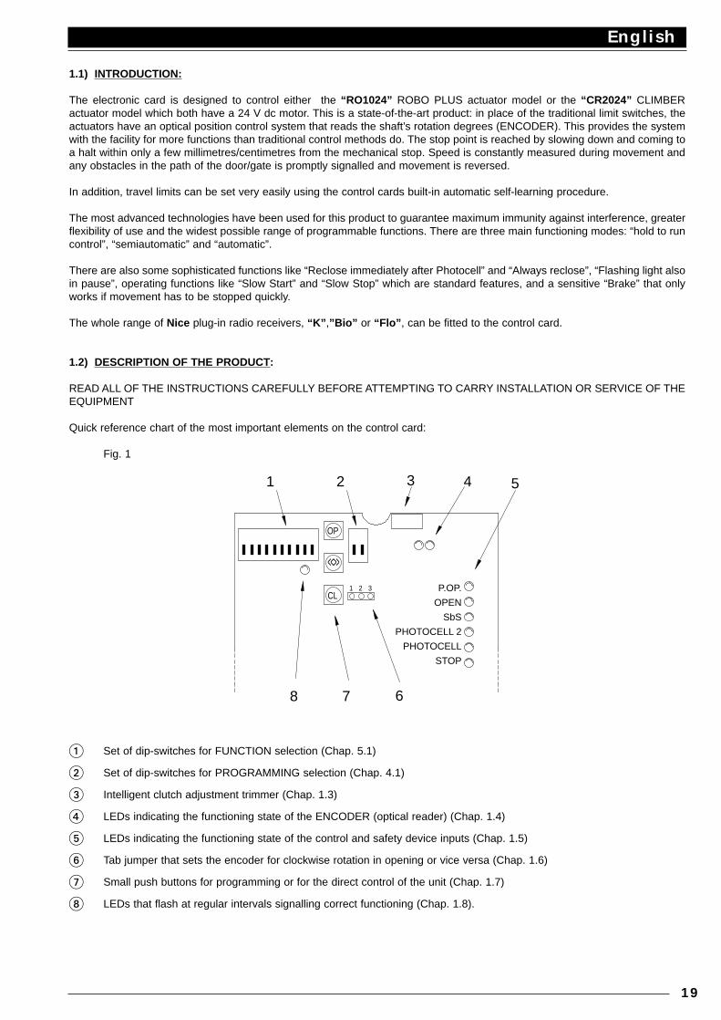
READ ALL OF THE INSTRUCTIONS CAREFULLY BEFORE ATTEMPTING TO CARRY INSTALLATION OR SERVICE OF THEEQUIPMENT
Quick reference chart of the most important elements on the control card:
Fig. 1
1 Set of dip-switches for FUNCTION selection (Chap. 5.1)
2 Set of dip-switches for PROGRAMMING selection (Chap. 4.1)
3 Intelligent clutch adjustment trimmer (Chap. 1.3)
4 LEDs indicating the functioning state of the ENCODER (optical reader) (Chap. 1.4)
5 LEDs indicating the functioning state of the control and safety device inputs (Chap. 1.5)
6 Tab jumper that sets the encoder for clockwise rotation in opening or vice versa (Chap. 1.6)
7 Small push buttons for programming or for the direct control of the unit (Chap. 1.7)
8 LEDs that flash at regular intervals signalling correct functioning (Chap. 1.8).
English
19
31 2CL
68 7
3
OP
<<>>
21 54
P.OP.
OPEN
SbS
PHOTOCELL 2
PHOTOCELL
STOP
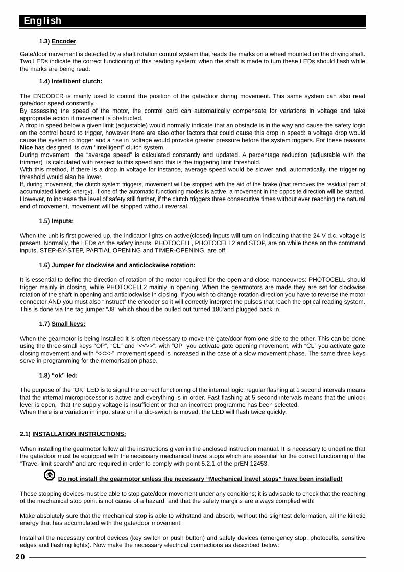
1.3) Encoder
Gate/door movement is detected by a shaft rotation control system that reads the marks on a wheel mounted on the driving shaft.Two LEDs indicate the correct functioning of this reading system: when the shaft is made to turn these LEDs should flash whilethe marks are being read.
1.4) Intellibent clutch:
The ENCODER is mainly used to control the position of the gate/door during movement. This same system can also readgate/door speed constantly.By assessing the speed of the motor, the control card can automatically compensate for variations in voltage and takeappropriate action if movement is obstructed. A drop in speed below a given limit (adjustable) would normally indicate that an obstacle is in the way and cause the safety logicon the control board to trigger, however there are also other factors that could cause this drop in speed: a voltage drop wouldcause the system to trigger and a rise in voltage would provoke greater pressure before the system triggers. For these reasonsNice has designed its own “intelligent” clutch system.During movement the “average speed” is calculated constantly and updated. A percentage reduction (adjustable with thetrimmer) is calculated with respect to this speed and this is the triggering limit threshold.With this method, if there is a drop in voltage for instance, average speed would be slower and, automatically, the triggeringthreshold would also be lower.If, during movement, the clutch system triggers, movement will be stopped with the aid of the brake (that removes the residual part ofaccumulated kinetic energy). If one of the automatic functioning modes is active, a movement in the opposite direction will be started. However, to increase the level of safety still further, if the clutch triggers three consecutive times without ever reaching the naturalend of movement, movement will be stopped without reversal.
1.5) Imputs:
When the unit is first powered up, the indicator lights on active(closed) inputs will turn on indicating that the 24 V d.c. voltage ispresent. Normally, the LEDs on the safety inputs, PHOTOCELL, PHOTOCELL2 and STOP, are on while those on the commandinputs, STEP-BY-STEP, PARTIAL OPENING and TIMER-OPENING, are off.
1.6) Jumper for clockwise and anticlockwise rotation:
It is essential to define the direction of rotation of the motor required for the open and close manoeuvres: PHOTOCELL shouldtrigger mainly in closing, while PHOTOCELL2 mainly in opening. When the gearmotors are made they are set for clockwiserotation of the shaft in opening and anticlockwise in closing. If you wish to change rotation direction you have to reverse the motorconnector AND you must also “instruct” the encoder so it will correctly interpret the pulses that reach the optical reading system.This is done via the tag jumper “J8” which should be pulled out turned 180’and plugged back in.
1.7) Small keys:
When the gearmotor is being installed it is often necessary to move the gate/door from one side to the other. This can be doneusing the three small keys “OP”, “CL” and “<<>>”: with “OP” you activate gate opening movement, with “CL” you activate gateclosing movement and with “<<>>” movement speed is increased in the case of a slow movement phase. The same three keysserve in programming for the memorisation phase.
1.8) “ok” led:
The purpose of the “OK” LED is to signal the correct functioning of the internal logic: regular flashing at 1 second intervals meansthat the internal microprocessor is active and everything is in order. Fast flashing at 5 second intervals means that the unlocklever is open, that the supply voltage is insufficient or that an incorrect programme has been selected.When there is a variation in input state or if a dip-switch is moved, the LED will flash twice quickly.
2.1) INSTALLA TION INSTRUCTIONS:
When installing the gearmotor follow all the instructions given in the enclosed instruction manual. It is necessary to underline thatthe gate/door must be equipped with the necessary mechanical travel stops which are essential for the correct functioning of the“Travel limit search” and are required in order to comply with point 5.2.1 of the prEN 12453.
Do not install the gearmotor unless the necessary “Mechanical travel stops” have been installed!
These stopping devices must be able to stop gate/door movement under any conditions; it is advisable to check that the reachingof the mechanical stop point is not cause of a hazard and that the safety margins are always complied with!
Make absolutely sure that the mechanical stop is able to withstand and absorb, without the slightest deformation, all the kineticenergy that has accumulated with the gate/door movement!
Install all the necessary control devices (key switch or push button) and safety devices (emergency stop, photocells, sensitiveedges and flashing lights). Now make the necessary electrical connections as described below:
English
20
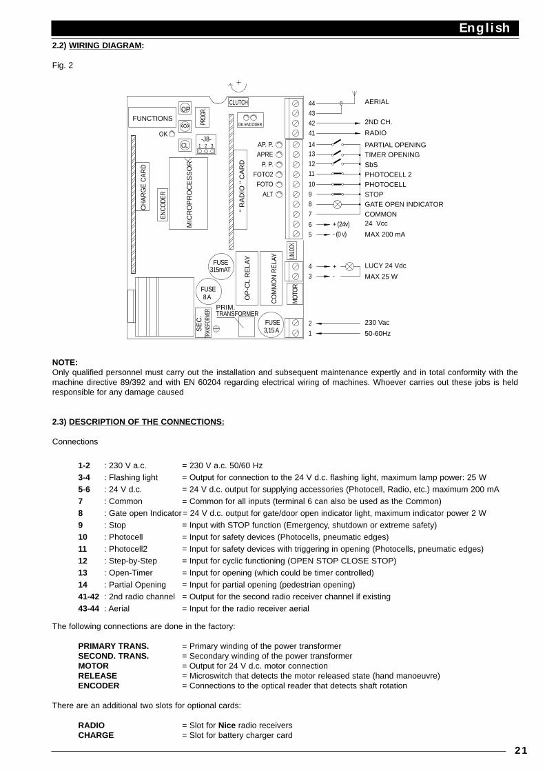
2.2) WIRING DIAGRAM:
Fig. 2
NOTE:Only qualified personnel must carry out the installation and subsequent maintenance expertly and in total conformity with themachine directive 89/392 and with EN 60204 regarding electrical wiring of machines. Whoever carries out these jobs is heldresponsible for any damage caused
2.3) DESCRIPTION OF THE CONNECTIONS:
Connections
1-2 : 230 V a.c. = 230 V a.c. 50/60 Hz3-4 : Flashing light = Output for connection to the 24 V d.c. flashing light, maximum lamp power: 25 W5-6 : 24 V d.c. = 24 V d.c. output for supplying accessories (Photocell, Radio, etc.) maximum 200 mA7 : Common = Common for all inputs (terminal 6 can also be used as the Common)8 : Gate open Indicator= 24 V d.c. output for gate/door open indicator light, maximum indicator power 2 W9 : Stop = Input with STOP function (Emergency, shutdown or extreme safety)10 : Photocell = Input for safety devices (Photocells, pneumatic edges)11 : Photocell2 = Input for safety devices with triggering in opening (Photocells, pneumatic edges)12 : Step-by-Step = Input for cyclic functioning (OPEN STOP CLOSE STOP)13 : Open-Timer = Input for opening (which could be timer controlled)14 : Partial Opening = Input for partial opening (pedestrian opening)41-42 : 2nd radio channel = Output for the second radio receiver channel if existing43-44 : Aerial = Input for the radio receiver aerial
The following connections are done in the factory:
PRIMARY TRANS. = Primary winding of the power transformerSECOND. TRANS. = Secondary winding of the power transformerMOTOR = Output for 24 V d.c. motor connectionRELEASE = Microswitch that detects the motor released state (hand manoeuvre)ENCODER = Connections to the optical reader that detects shaft rotation
There are an additional two slots for optional cards:
RADIO = Slot for Nice radio receiversCHARGE = Slot for battery charger card
English
21
MIC
RO
PR
OC
ES
SO
RALT 9
CH
AR
GE
CA
RD
" R
AD
IO "
CA
RD
8 AFUSE
ENCO
DER
FUSE315mAT
MO
TOR
FUSE3,15 A 1
2
CO
MM
ON
RE
LAY
OP
-CL
RE
LAY
3
8
4
UNLO
CK
65
+ (24v)
7
- (0 v)
+-
OK ENCODER
CLUTCH
OK
31 2-J8-
CL
<<>>
OPFUNCTIONS
PROG
R.
11
FOTO 10
41
4342
1312
14
44
AP. P.APRE
P. P.FOTO2
AERIAL
2ND CH.
RADIO
PARTIAL OPENING TIMER OPENING SbS PHOTOCELL 2 PHOTOCELL STOP GATE OPEN INDICATOR COMMON 24 Vcc
MAX 200 mA
LUCY 24 Vdc
MAX 25 W
230 Vac
50-60Hz
SE
C.
TRAN
SFOR
MER PRIM.
TRANSFORMER
2.4) INSTRUCTIONS FOR CONNECTIONS:
Disconnect all power (24V and 230V) before carrying out any work on the system
We recommend waiting until installation is complete, the system tested and correct operation verified before plugging in theoptional RADIO or CHARGE cards. The optional cards are not necessary for the working of the system and if they are used theymake troubleshooting more complex.
If the inputs of the NC (Normally Closed) contacts are not used they should be linked out; if there is more than one then theyshould be placed in SERIES with one another; if the inputs of the NO (Normally Open) contacts are not used they should be leftfree. The inputs must be of the voltage free mechanical type; DO NOT USE Open Collector type inputs (“PNP”, “NPN” etc.).
A) Carry out the necessary connections, following the diagram in Fig. 1; remember that there are specific standards that mustbe complied with both as regards the safety of the electrical systems and as regards automatic doors and gates.
B) Power the door/gate and position it halfway, turn power off. It is now free to be opened or closed.
Do not power the gearmotor unless the necessary “Mechanical travel stops” have been installed!
C) Power the unit, checking immediately that a voltage of 230 V a.c. reaches terminals 1-2 and a voltage of 24 V d.c. reachesterminals 5-6. As soon as the unit is powered the indicator lights (LEDs) on the active inputs should turn on and shortly after the“OK” LED should start flashing regularly. If none of this happens, turn power off immediately and check the connections morecarefully.
The “OK” LED in the centre of the card has the job of signalling the state of the internal logic: regular flashing at 1 second intervalsmeans that the internal microprocessor is active and waiting for commands. When the microprocessor recognises a variation inthe state of an input (whether it is a command or function Switch input) it generates a quick double flash even if the variationdoes not have any immediate effect. Quick flashing at 5 second intervals means that the release lever is open, the power voltageis insufficient or an incorrect programme has been selected (see Chapter 4.1).
D) Now check that the LEDs relative to the NC contacts are on (all safety devices active) and that the LEDs relative to the NOinputs are off (no command present); if this is not the case, check connections and effectiveness of the various devices.
E) Check that all the unit’s safety devices are in proper working order (emergency stop, photocells, pneumatic edges, etc.): eachtime they trigger the relative STOP, PHOTO or PHOTO2 LEDs, should turn off.
Do not move the gearmotor unless the necessary “Mechanical travel stops” have been installed!
F) The last thing to do is to check if movement is in the right direction. In the factory all the gearmotors are set for clockwiserotation of the shaft in opening and anticlockwise in closing. To check that this is so, just press the small “CLOSE” key and seewhether or not the gate/door moves in the closing direction.
Whether the direction of movement is right or not, it is advisable to stop the manoeuvre immediately by pressing the small“CLOSE” key again.Now, if movement was not in the direction it should be then proceed as follows:
1 - Turn power off
2 - Unplug the “MOTOR” connector and plug it back in after having turned it 180°
3 - Unplug the jumper on the connector, “J8”, turn it 180’and plug it back into the symmetrically opposite position
Once you have done this it is advisable to try movement again to see if the direction is correct, repeating the procedure inparagraph “F”.
NOTE:When movement is reversed then all three operations described above must be carried out., If you turn the “MOTOR” connectorbut you do not move the “J8” jumper, an error will be generated in the shaft rotation reading system (the gearmotor is controlledin the opening phase but the system reads a movement in the closing phase) and in this case any attempt to move is stoppedstraight away. This situation can be seen by means of the two “Ok-Encoder” LEDs that blink briefly after which the motor stopsimmediately.
English
22
3.1) TRAVEL LIMITS:
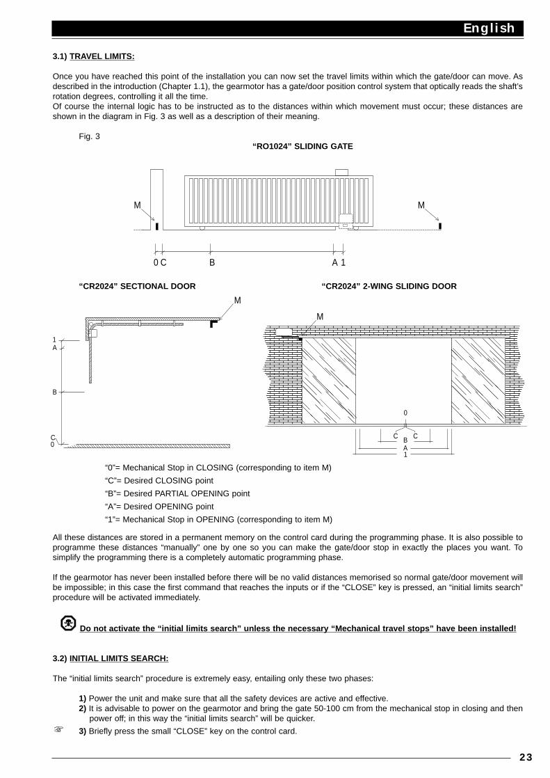
Once you have reached this point of the installation you can now set the travel limits within which the gate/door can move. Asdescribed in the introduction (Chapter 1.1), the gearmotor has a gate/door position control system that optically reads the shaft’srotation degrees, controlling it all the time.Of course the internal logic has to be instructed as to the distances within which movement must occur; these distances areshown in the diagram in Fig. 3 as well as a description of their meaning.
Fig. 3“RO1024” SLIDING GATE
“CR2024” SECTIONAL DOOR “CR2024” 2-WING SLIDING DOOR
“0”= Mechanical Stop in CLOSING (corresponding to item M)
“C”= Desired CLOSING point
“B”= Desired PARTIAL OPENING point
“A”= Desired OPENING point
“1”= Mechanical Stop in OPENING (corresponding to item M)
All these distances are stored in a permanent memory on the control card during the programming phase. It is also possible toprogramme these distances “manually” one by one so you can make the gate/door stop in exactly the places you want. Tosimplify the programming there is a completely automatic programming phase.
If the gearmotor has never been installed before there will be no valid distances memorised so normal gate/door movement willbe impossible; in this case the first command that reaches the inputs or if the “CLOSE” key is pressed, an “initial limits search”procedure will be activated immediately.
Do not activate the “initial limits search” unless the necessary “Mechanical travel stops” have been installed!
3.2) INITIAL LIMITS SEARCH:
The “initial limits search” procedure is extremely easy, entailing only these two phases:
1) Power the unit and make sure that all the safety devices are active and effective.2) It is advisable to power on the gearmotor and bring the gate 50-100 cm from the mechanical stop in closing and then
power off; in this way the “initial limits search” will be quicker.
3) Briefly press the small “CLOSE” key on the control card.
English
23
MM
0 C B A 1
M
M
1A
B
C 0
C C
0
BA1
The motor will now move the gate/door slowly in the closing direction until point “0” is detected (mechanical stop that defines themaximum closing point). Once point “0” is reached the gate/door stops, causing the intelligent clutch system to work (see Chapter1.3) and the close mechanical stop point detected by the encoder will be used to reset the “distance counter”. Immediately after,the gearmotor will move the gate/door slowly in the opening direction until point “1” is detected (the other mechanical stop thatdefines the maximum opening point); when point “1” is reached, the gate/door stops and the distance is memorised.
The maximum travel limits have been measured with these two operations. With a mathematical operation point “C” is calculatedwhich is set, if used like RO1024 (with switch 10 in the OFF position) 5 centimetres from point “0”.Point “A” is set a few centimetres before point “1” and, lastly, point “B” is set, in the case of CR2024, halfway between points “0”and “1” while in the case of RO1024, 1 metre from point “C”.
Now all the distances are memorised and finally the gate/door will move quickly until it reaches point “C”.
4) the “initial limits search” procedure is now completed. Set the function dip-switches in the mode required and thegearmotor is ready to use
As the procedure described memorises the distances that have just been measured automatically, no other operations arenecessary.
If, during the “initial limits search”, an external event occurs (another small key is pressed, the Photocell triggers or there is aStep-by-Step pulse) gate movement will be stopped immediately, and the operation must be repeated from point (3).Subsequent to an initial search, if you wish to, you can modify any of the distances measured (except for distance 0) by meansof the manual search.
4.1) PROGRAMMING:
As an alternative to the “initial limits search” which only takes place if the gearmotor has never been installed before, it is possible,at any time, to activate an “automatic limit search” or to directly establish each single position by manual programming.
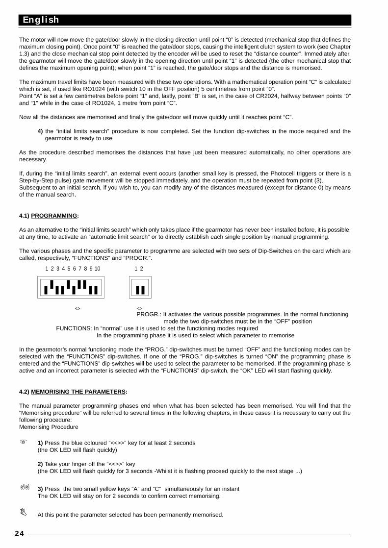
The various phases and the specific parameter to programme are selected with two sets of Dip-Switches on the card which arecalled, respectively, “FUNCTIONS” and “PROGR.”.
a aPROGR.: It activates the various possible programmes. In the normal functioning
mode the two dip-switches must be in the “OFF” positionFUNCTIONS: In “normal” use it is used to set the functioning modes required
In the programming phase it is used to select which parameter to memorise
In the gearmotor’s normal functioning mode the “PROG.” dip-switches must be turned “OFF” and the functioning modes can beselected with the “FUNCTIONS” dip-switches. If one of the “PROG.” dip-switches is turned “ON” the programming phase isentered and the “FUNCTIONS” dip-switches will be used to select the parameter to be memorised. If the programming phase isactive and an incorrect parameter is selected with the “FUNCTIONS” dip-switch, the “OK” LED will start flashing quickly.
4.2) MEMORISING THE PARAMETERS:
The manual parameter programming phases end when what has been selected has been memorised. You will find that the“Memorising procedure” will be referred to several times in the following chapters, in these cases it is necessary to carry out thefollowing procedure:Memorising Procedure
1) Press the blue coloured “<<>>” key for at least 2 seconds(the OK LED will flash quickly)
2) Take your finger off the “<<>>” key(the OK LED will flash quickly for 3 seconds -Whilst it is flashing proceed quickly to the next stage ...)
3) Press the two small yellow keys “A” and “C” simultaneously for an instantThe OK LED will stay on for 2 seconds to confirm correct memorising.
At this point the parameter selected has been permanently memorised.
English
24
1 2 3 4 5 6 7 8 9 10 1 2
4.3) MANUALLY PROGRAMMING THE DISTANCES:
All the distances described in the previous chapter can be programmed manually:
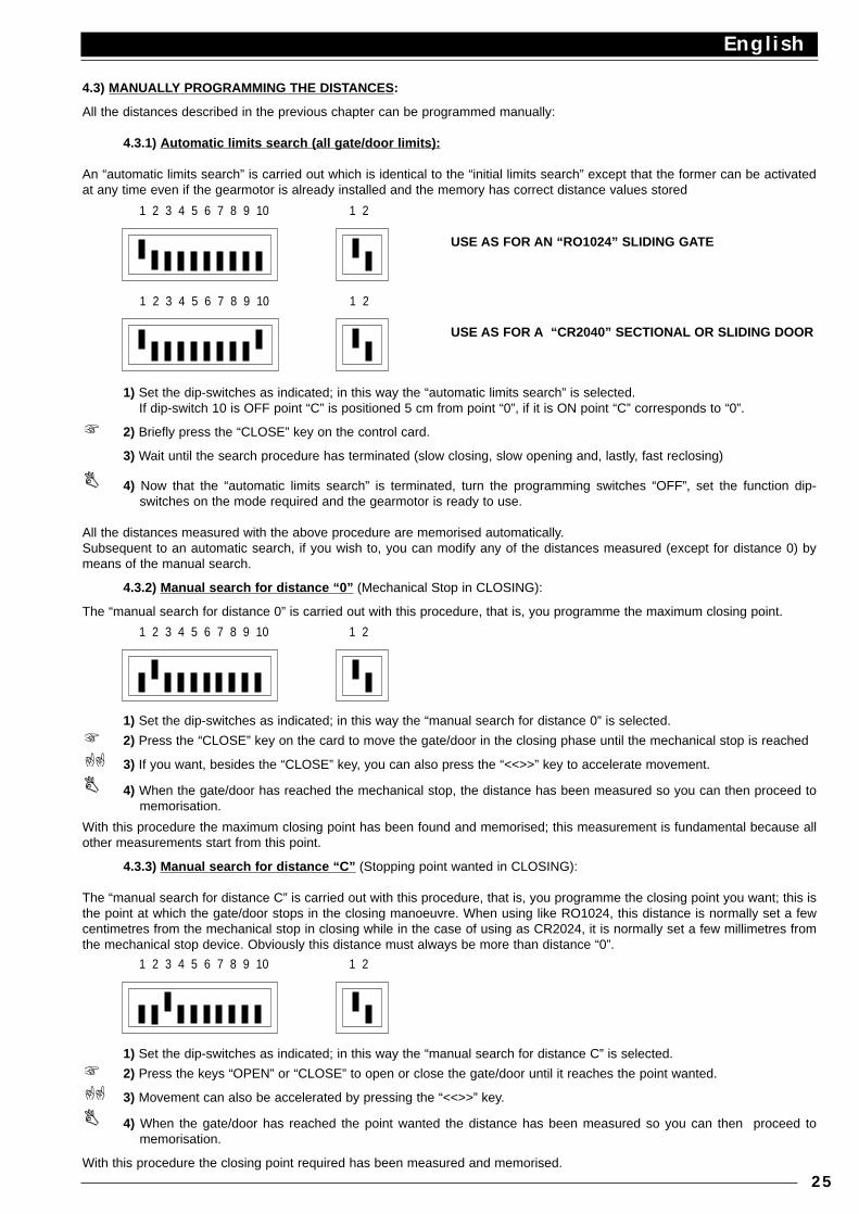
4.3.1) Automatic limits search (all gate/door limits):
An “automatic limits search” is carried out which is identical to the “initial limits search” except that the former can be activatedat any time even if the gearmotor is already installed and the memory has correct distance values stored
1) Set the dip-switches as indicated; in this way the “automatic limits search” is selected.If dip-switch 10 is OFF point “C” is positioned 5 cm from point “0”, if it is ON point “C” corresponds to “0”.
2) Briefly press the “CLOSE” key on the control card.
3) Wait until the search procedure has terminated (slow closing, slow opening and, lastly, fast reclosing)
4) Now that the “automatic limits search” is terminated, turn the programming switches “OFF”, set the function dip-switches on the mode required and the gearmotor is ready to use.
All the distances measured with the above procedure are memorised automatically. Subsequent to an automatic search, if you wish to, you can modify any of the distances measured (except for distance 0) bymeans of the manual search.
4.3.2) Manual search for distance “0” (Mechanical Stop in CLOSING):
The “manual search for distance 0” is carried out with this procedure, that is, you programme the maximum closing point.
1) Set the dip-switches as indicated; in this way the “manual search for distance 0” is selected.
2) Press the “CLOSE” key on the card to move the gate/door in the closing phase until the mechanical stop is reached
3) If you want, besides the “CLOSE” key, you can also press the “<<>>” key to accelerate movement.
4) When the gate/door has reached the mechanical stop, the distance has been measured so you can then proceed tomemorisation.
With this procedure the maximum closing point has been found and memorised; this measurement is fundamental because allother measurements start from this point.
4.3.3) Manual search for distance “C” (Stopping point wanted in CLOSING):
The “manual search for distance C” is carried out with this procedure, that is, you programme the closing point you want; this isthe point at which the gate/door stops in the closing manoeuvre. When using like RO1024, this distance is normally set a fewcentimetres from the mechanical stop in closing while in the case of using as CR2024, it is normally set a few millimetres fromthe mechanical stop device. Obviously this distance must always be more than distance “0”.
1) Set the dip-switches as indicated; in this way the “manual search for distance C” is selected.
2) Press the keys “OPEN” or “CLOSE” to open or close the gate/door until it reaches the point wanted.
3) Movement can also be accelerated by pressing the “<<>>” key.
4) When the gate/door has reached the point wanted the distance has been measured so you can then proceed tomemorisation.
With this procedure the closing point required has been measured and memorised.
English
25
1 2 3 4 5 6 7 8 9 10 1 2
1 2 3 4 5 6 7 8 9 10 1 2
USE AS FOR AN “RO1024” SLIDING GATE
USE AS FOR A “CR2040” SECTIONAL OR SLIDING DOOR
1 2 3 4 5 6 7 8 9 10 1 2
1 2 3 4 5 6 7 8 9 10 1 2
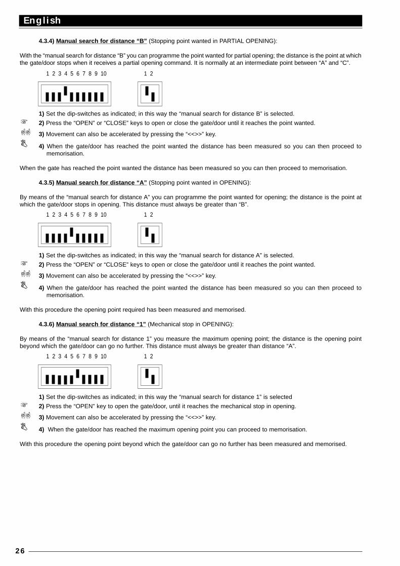
4.3.4) Manual search for distance “B” (Stopping point wanted in PARTIAL OPENING):
With the “manual search for distance “B” you can programme the point wanted for partial opening; the distance is the point at whichthe gate/door stops when it receives a partial opening command. It is normally at an intermediate point between “A” and “C”.
1) Set the dip-switches as indicated; in this way the “manual search for distance B” is selected.
2) Press the “OPEN” or “CLOSE” keys to open or close the gate/door until it reaches the point wanted.
3) Movement can also be accelerated by pressing the “<<>>” key.
4) When the gate/door has reached the point wanted the distance has been measured so you can then proceed tomemorisation.
When the gate has reached the point wanted the distance has been measured so you can then proceed to memorisation.
4.3.5) Manual search for distance “A” (Stopping point wanted in OPENING):
By means of the “manual search for distance A” you can programme the point wanted for opening; the distance is the point atwhich the gate/door stops in opening. This distance must always be greater than “B”.
1) Set the dip-switches as indicated; in this way the “manual search for distance A” is selected.
2) Press the “OPEN” or “CLOSE” keys to open or close the gate/door until it reaches the point wanted.
3) Movement can also be accelerated by pressing the “<<>>” key.
4) When the gate/door has reached the point wanted the distance has been measured so you can then proceed tomemorisation.
With this procedure the opening point required has been measured and memorised.
4.3.6) Manual search for distance “1” (Mechanical stop in OPENING):
By means of the “manual search for distance 1” you measure the maximum opening point; the distance is the opening pointbeyond which the gate/door can go no further. This distance must always be greater than distance “A”.
1) Set the dip-switches as indicated; in this way the “manual search for distance 1” is selected
2) Press the “OPEN” key to open the gate/door, until it reaches the mechanical stop in opening.
3) Movement can also be accelerated by pressing the “<<>>” key.
4) When the gate/door has reached the maximum opening point you can proceed to memorisation.
With this procedure the opening point beyond which the gate/door can go no further has been measured and memorised.
English
26
1 2 3 4 5 6 7 8 9 10 1 2
1 2 3 4 5 6 7 8 9 10 1 2
1 2 3 4 5 6 7 8 9 10 1 2
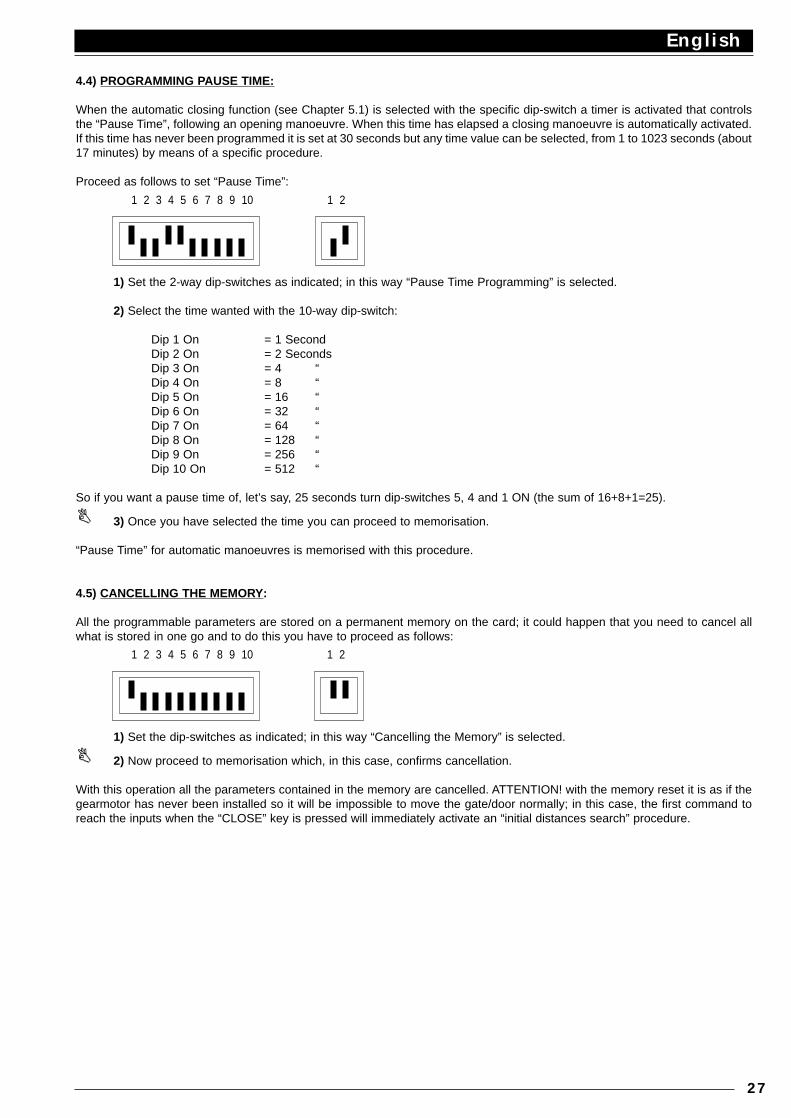
4.4) PROGRAMMING PAUSE TIME:
When the automatic closing function (see Chapter 5.1) is selected with the specific dip-switch a timer is activated that controlsthe “Pause Time”, following an opening manoeuvre. When this time has elapsed a closing manoeuvre is automatically activated.If this time has never been programmed it is set at 30 seconds but any time value can be selected, from 1 to 1023 seconds (about17 minutes) by means of a specific procedure.
Proceed as follows to set “Pause Time”:
1) Set the 2-way dip-switches as indicated; in this way “Pause Time Programming” is selected.
2) Select the time wanted with the 10-way dip-switch:
Dip 1 On = 1 SecondDip 2 On = 2 SecondsDip 3 On = 4 “Dip 4 On = 8 “Dip 5 On = 16 “Dip 6 On = 32 “Dip 7 On = 64 “Dip 8 On = 128 “Dip 9 On = 256 “Dip 10 On = 512 “
So if you want a pause time of, let’s say, 25 seconds turn dip-switches 5, 4 and 1 ON (the sum of 16+8+1=25).
3) Once you have selected the time you can proceed to memorisation.
“Pause Time” for automatic manoeuvres is memorised with this procedure.
4.5) CANCELLING THE MEMORY:
All the programmable parameters are stored on a permanent memory on the card; it could happen that you need to cancel allwhat is stored in one go and to do this you have to proceed as follows:
1) Set the dip-switches as indicated; in this way “Cancelling the Memory” is selected.
2) Now proceed to memorisation which, in this case, confirms cancellation.
With this operation all the parameters contained in the memory are cancelled. ATTENTION! with the memory reset it is as if thegearmotor has never been installed so it will be impossible to move the gate/door normally; in this case, the first command toreach the inputs when the “CLOSE” key is pressed will immediately activate an “initial distances search” procedure.
English
27
1 2 3 4 5 6 7 8 9 10 1 2
1 2 3 4 5 6 7 8 9 10 1 2
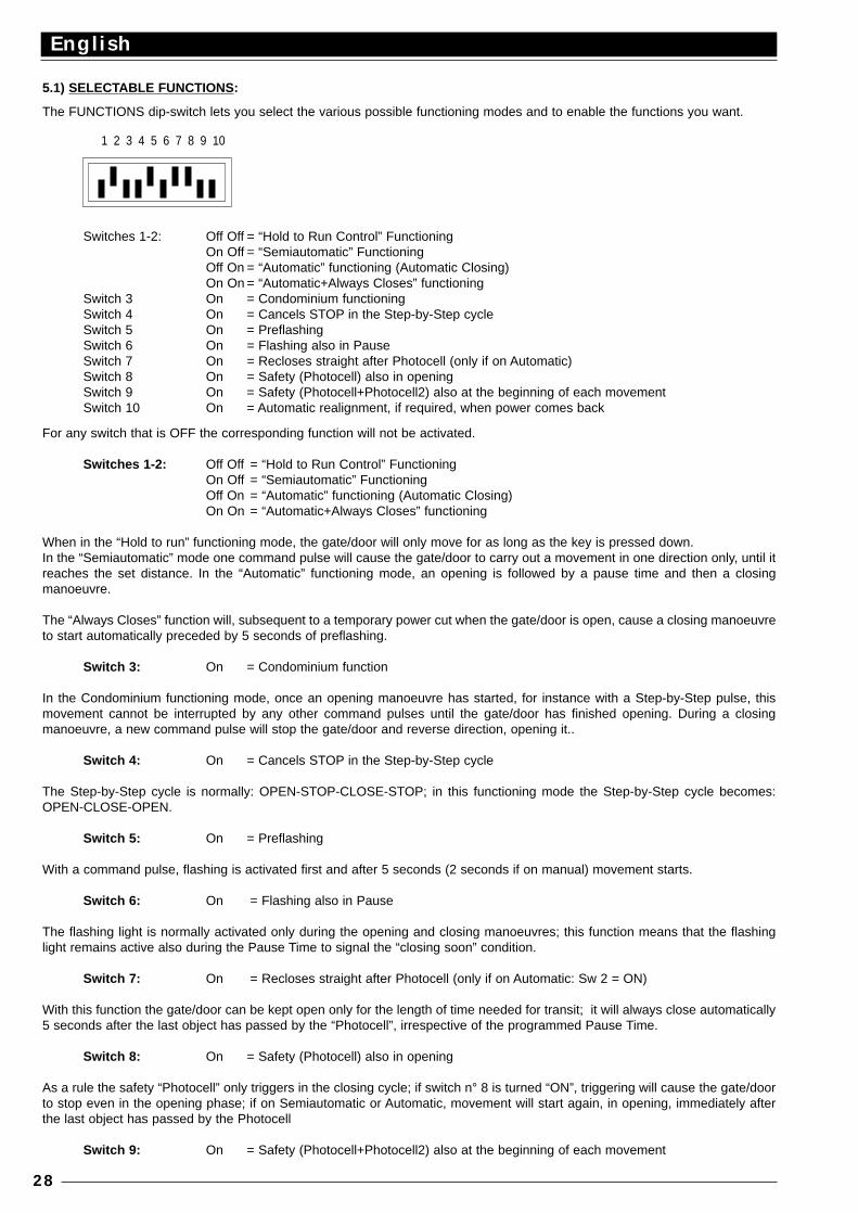
5.1) SELECTABLE FUNCTIONS :
The FUNCTIONS dip-switch lets you select the various possible functioning modes and to enable the functions you want.
Switches 1-2: Off Off = “Hold to Run Control” FunctioningOn Off = “Semiautomatic” FunctioningOff On = “Automatic” functioning (Automatic Closing)On On = “Automatic+Always Closes” functioning
Switch 3 On = Condominium functioningSwitch 4 On = Cancels STOP in the Step-by-Step cycleSwitch 5 On = PreflashingSwitch 6 On = Flashing also in PauseSwitch 7 On = Recloses straight after Photocell (only if on Automatic)Switch 8 On = Safety (Photocell) also in openingSwitch 9 On = Safety (Photocell+Photocell2) also at the beginning of each movementSwitch 10 On = Automatic realignment, if required, when power comes back
For any switch that is OFF the corresponding function will not be activated.
Switches 1-2: Off Off = “Hold to Run Control” FunctioningOn Off = “Semiautomatic” FunctioningOff On = “Automatic” functioning (Automatic Closing)On On = “Automatic+Always Closes” functioning
When in the “Hold to run” functioning mode, the gate/door will only move for as long as the key is pressed down.In the “Semiautomatic” mode one command pulse will cause the gate/door to carry out a movement in one direction only, until itreaches the set distance. In the “Automatic” functioning mode, an opening is followed by a pause time and then a closingmanoeuvre.
The “Always Closes” function will, subsequent to a temporary power cut when the gate/door is open, cause a closing manoeuvreto start automatically preceded by 5 seconds of preflashing.
Switch 3: On = Condominium function
In the Condominium functioning mode, once an opening manoeuvre has started, for instance with a Step-by-Step pulse, thismovement cannot be interrupted by any other command pulses until the gate/door has finished opening. During a closingmanoeuvre, a new command pulse will stop the gate/door and reverse direction, opening it..
Switch 4: On = Cancels STOP in the Step-by-Step cycle
The Step-by-Step cycle is normally: OPEN-STOP-CLOSE-STOP; in this functioning mode the Step-by-Step cycle becomes:OPEN-CLOSE-OPEN.
Switch 5: On = Preflashing
With a command pulse, flashing is activated first and after 5 seconds (2 seconds if on manual) movement starts.
Switch 6: On = Flashing also in Pause
The flashing light is normally activated only during the opening and closing manoeuvres; this function means that the flashinglight remains active also during the Pause Time to signal the “closing soon” condition.
Switch 7: On = Recloses straight after Photocell (only if on Automatic: Sw 2 = ON)
With this function the gate/door can be kept open only for the length of time needed for transit; it will always close automatically5 seconds after the last object has passed by the “Photocell”, irrespective of the programmed Pause Time.
Switch 8: On = Safety (Photocell) also in opening
As a rule the safety “Photocell” only triggers in the closing cycle; if switch n° 8 is turned “ON”, triggering will cause the gate/doorto stop even in the opening phase; if on Semiautomatic or Automatic, movement will start again, in opening, immediately afterthe last object has passed by the Photocell
Switch 9: On = Safety (Photocell+Photocell2) also at the beginning of each movement
English
28
1 2 3 4 5 6 7 8 9 10
Usually the safety “Photocell” triggers only during the closing manoeuvre and “Photocell2” only during the opening manoeuvre.If you wish to increase the level of safety it is possible to programme the system to check that the safety devices “PHOTOCELL”and “PHOTOCELL2”are clear before movement can start.
Switch 10: On = Automatic realignment, if required, when power returns
When there is a power cut and the gate/door is without power, the gate/door position reading system loses the distance; in suchcircumstances the “Realignment” procedure has been designed that will search for point “C” again. The realignment procedureis normally carried out when power returns, when the first command pulse is received. With dip-switch n° 10 “ON” realignmentoccurs as soon as power returns, without waiting from any command pulse
6.1) FUNCTIONING TESTS:
After the connections have been checked and verified (Chapter 2.4), and the travel limits programming phase has been carriedout (Chapter 3.2 or 4.3.1), it is possible to test actuator movement. We suggest you work in the “hold to run control” functioningmode with all the functions deactivated (all switches OFF); in all cases, in the “hold to run control” mode, by releasing thecommand key, the motor stops immediately. If you use the Step-by-Step input command the first movement (after turning on) willbe an opening manoeuvre. In this phase you will find it extremely easy to use the small keys “OP”, “CL” on the card. By meansof the command inputs, move the gate/door up to the point of opening “A” wanted. About 20 cm before the stop position, the“slowing” phase must come into play so the gate/door reaches the stop position at a speed reduced by about 30%. Now carryout a closing manoeuvre up to the point of closing “C” you want. Here too, the slowing down phase should start 20 cm beforethe stopping point. Now test triggering of the safety devices: PHOTOCELL in the opening phase has no effect; in the closingphase it will stop movement; PHOTOCELL2 has no effect in the closing phase; in the opening phase it will stop movement. Thedevices connected to the STOP input act both in the opening and closing manoeuvres, stopping movement.
The recent European standards, prEN 12453: safety in using motorised doors - requirements and classifications; prEN 12445:safety in using motorised doors - testing methods; (not yet approved but they will be in 1998), require the use of measurementsso as to limit the forces involved in moving automatic doors, equal to a maximum of 1400N as the force of impact and a maximumresidual static force of 150N that must be cancelled out within 5 seconds from impact. The FRIZZ (clutch) trimmer is on the cardand is used to establish the clutch’s intervention threshold.
As described in Chapter 1.4, the intelligent clutch system calculates to find the average movement speed so it can intervene withgreater precision. To evaluate the effect the adjustment has on the trimmer it is best to wait for movement to start and for thegate/door to reach standard speed. Also ensure for safety reasons, that if the clutch intervenes three times in a row, movementis stopped without any reversal.
If the automatic functioning mode is selected, at the end of the opening manoeuvre there is a “pause time” followed automaticallyby a closing manoeuvre. Pause time, if not programmed, will be 30 seconds
The pause will also be activated in the semiautomatic movement phase when, in closing, the triggering of a safety device or theintelligent clutch, causes a reversal in opening.
Only now, when all the adjustments have been made and with the electricity off, do we advise you to connect the radio receiver.
6.2) DESCRIPTION OF THE FUNCTIONING MODES:
In the “hold to run control” functioning mode the OPEN-TIMER input allows movement up to the opening point wanted; the PAR-OPEN input allows movement up to the partial opening point; STEP-BY-STEP allows alternative opening and closingmanoeuvres; as soon as the command in input stops, movement stops. In the opening phase the gate/door will stop in the setposition or if PHOTOCELL2 is interrupted; in the closing phase movement will stop if the PHOTOCELL input is interrupted. Anaction on STOP will cause movement to stop immediately both in opening and closing. Once movement has stopped thecommand in input has to be stopped too before any new movements can be started
In any of the automatic functioning modes (semiautomatic-automatic and closes always) a command on the OPEN-TIMER inputwill cause an opening manoeuvre; if the command persists after the gate has opened, movement remains “frozen” in an infinitepause; only when the command stops will the gate/door be able to close. Command pulses on the PAR-OPEN input will causean opening manoeuvre only up to the partial opening point. A pulse on the STEP-BY-STEP causes alternative opening andclosing manoeuvres. A second pulse on the STEP-BY-STEP or on the same input that started the movement, will cause a Stop.
STOP will cause movement to stop immediately both in opening and closing.
If in a command input there is a continuous signal instead of a pulse, it will cause a “priority” state which means all the othercommand inputs remain disabled (useful to connect a timer or Night-Day selector).
If the automatic functioning mode is being used, subsequent to an opening manoeuvre there will be a pause time followed by aclosing manoeuvre. If, during the pause the PHOTO triggers, the timer will be reset with a new time; if, on the other hand, a STOPintervenes during the pause, the reclosing function is cancelled and there will be a STOP condition.
Triggering of the PHOTOCELL has no effect in an opening manoeuvre while PHOTOCELL2 causes reversal of direction. In aclosing manoeuvre triggering of the PHOTOCELL will reverse the direction followed by a new pause and then a closingmanoeuvre. If, at the beginning of an opening manoeuvre, the PHOTOCELL input is not clear, the request to open is cancelled.
English
29
7.1) “CHARGE” CARD also battery powered
The unit is equipped with a power transformer that can provide the motor’s power requirement and that of the electronic card soit can all be powered directly by the mains.
If you want the system to continue working in the case of a power cut then you have to add a suitable battery and the relativebattery charger card.
Due to the size of the battery it must be installed externally to the motor unit and connected to two terminals on the batterycharger card; the latter must be connected to the connector on the unit.
8) MAINTENANCE:
The card, being electronic, needs no particular maintenance. However check periodically, at least twice a year, the perfectefficiency and adjustment of the device that controls maximum motor force and, if required, adjust with the trimmer. Check effectiveness of the safety devices (photoelectric cells, pneumatic edges, etc.) and correct functioning of the flashing light.
TECHNICAL FEATURES OF THE UNIT:
Mains power : 230 Vac ±10% , 50 - 60 HzBattery power : 21 ÷ 28 Vdc (> 6Ah capacity)Max. Access: current 24 Vdc : 200 mAMax. flashing light power : 25 W ( 24 Vdc)Max gate-open power indicator : 2 W ( 24 Vdc)Pause time : from 1 to 1023 secondsEncoder resolution : 4.73 degrees (76 pulses/rev)Working temperature : -20 ÷ 70 °C
English
30
Français
31
Ce manuel est destiné exclusivement au personnel technique qualifié pour l’installationAucune information contenue dans ce fascicule ne peut être considérée comme intéressante pour l’utilisateur final!
TABLE DES MATIÈRES:
Guide rapide : 32Introduction : 33
Description du produit : 33Instructions pour l’installation : 34
Schéma des connexions : 35Description des connexions : 35Instructions pour les connexions : 36
Limites de la course : 37Recherche initiale des mesures : 38
Programmation : 38Mémorisation des paramètres : 39Programmation manuelle des mesures : 39Programmation du temps de pause : 41Effacement de la mémoire : 42
Fonctions sélectionnables : 42Essai de fonctionnement : 43Description des modes de fonctionnement : 44Carte “CHARGE” pour alimentation à batterie : 44Entretien : 44Caractéristiques techniques de la centrale : 44
RECOMMANDATION IMPORTANTE
Nous nous devons de rappeler que vous effectuez des opérations sur des installations appartenant à la catégorie: “Portails etportes automatiques” et donc considérées comme particulièrement “Dangereuses”; vous avez pour tâche de les rendre “s˚res”dans la mesure où cela est raisonnablement possible!L’installation et les éventuelles interventions de maintenance doivent être effectuées exclusivement par du personnel qualifié etexpérimenté, suivant les meilleures indications dictées par les “règles de l’art” et conformément aux lois, normes ou directivessuivantes:
89/392 CEE (Directive Machines)89/336 CEE (Directive sur la Compatibilité Électromagnétique)73/23 CEE (Directive Basse tension)PrEN 12453 (Sécurité dans l’emploi des portes motorisées: conditions requises et classifications)PrEN 12445 (Sécurité dans l’emploi des portes motorisées: méthodes d’essai)
Dans le projet et dans la fabrication de ses produits, Nice respecte toutes ces normes (en ce qui concerne ses appareils); il estindispensable toutefois que l’installateur lui aussi continue à respecter scrupuleusement ces mêmes normes (en ce qui concerneles installations).
Le personnel non qualifié ou n’étant pas à la connaissance des normes applicables à la catégorie des “Portails et portesautomatiques”
doit absolument s’abstenir d’effectuer les installations et de réaliser les circuits.
Qui réalise des installations sans respecter toutes les normes applicablessera tenu pour responsable des éventuels dommages que l’installation pourra provoquer!
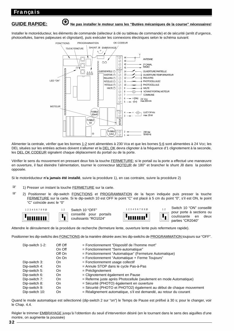
GUIDE RAPIDE: Ne pas installer le moteur sans les “Butées mécaniques de la course” nécessaires!
Installer le motoréducteur, les éléments de commande (sélecteur à clé ou tableau de commande) et de sécurité (arrêt d’urgence,photocellules, barres palpeuses et clignotant), puis exécuter les connexions électriques selon le schéma suivant:
Alimenter la centrale, vérifier que les bornes 1-2 sont alimentées à 230 Vca et que les bornes 5-6 sont alimentées à 24 Vcc; lesDEL situées sur les entrées actives doivent s’allumer et la DEL OK devra clignoter à la fréquence d’1 clignotement à la seconde,les DEL OK CODEUR signalent chaque déplacement du portail ou de la porte.
Vérifier le sens du mouvement en pressant deux fois la touche FERMETURE; si le portail ou la porte a effectué une manœuvreen ouverture, il faut éteindre l’alimentation, tourner le connecteur MOTEUR de 180° et brancher le shunt J8 dans la positionopposée.
Si le motoréducteur n’a jamais été installé , suivre la procédure 1), en cas contraire, suivre la procédure 2)
1) Presser un instant la touche FERMETURE sur la carte.
2) Positionner le dip-switch FONCTIONS et PROGRAMMATION de la façon indiquée puis presser la toucheFERMETURE sur la carte. Si le dip-switch 10 est OFF le point “C” est placé à 5 cm du point “0”, s’il est ON, le point“C” coïncide avec le “0”
Attendre le déroulement de la procédure de recherche (fermeture lente, ouverture lente puis refermeture rapide).
Positionner les dip-switchs des FONCTIONS de la manière désirée avec les dip-switchs de PROGRAMMATION toujours sur “OFF”.
Dip-switch 1-2: Off Off = Fonctionnement “Dispositif de l’homme mort”On Off = Fonctionnement “Semi-automatique”Off On = Fonctionnement “Automatique” (Fermeture Automatique)On On = Fonctionnement “Automatique + Ferme Toujours”
Dip-switch 3: On = Fonctionnement usage collectifDip-switch 4: On = Annule STOP dans le cycle Pas-à-PasDip-switch 5: On = PréclignotementDip-switch 6: On = Clignotement également en PauseDip-switch 7: On = Referme juste après Photocellule (seulement en mode Automatique)Dip-switch 8: On = Sécurité (PHOTO) également en ouvertureDip-switch 9: On = Sécurité (PHOTO et PHOTO2) également au début de chaque mouvementDip-switch 10: On = Réalignement automatique, s’il est demandé, au retour du courant
Quand le mode automatique est sélectionné (dip-switch 2 sur “on”) le Temps de Pause est préfixé à 30 s; pour le changer, voirle Chap. 4.4.
Régler le trimmer EMBRAYAGE jusqu’à l’obtention du seuil d’intervention désiré (en le tournant dans le sens des aiguilles d’unemontre, on augmente la poussée)
Français
32
24 Vccmax 200 mA- (0 v)
MOTEUR
8 A
315mAT
FUSIBLE
FUSIBLE
1
MOTE
UR
FUSIBLE3,15 A
2
34 +
-
LED "OK"
FONCTIONS
31 2
SHUNT J8
PROGRAMMATION
TOUCHE FERMETURE
HALTE 98
65
+ (24v)
7
11
PHOTOCELLULE 10
1312
14OUVERTURE PARTIELLE.OUVERTUREPAS-A-PASPHOTOCELLULE2
41
4342
44
EMBRAYAGE
OK CODEUR
50-60 Hz230 Vac
LUCY 24 Vccmax 25 W
HALTEVOYANT PORTAIL MOTEURCOMMUNE
PHOTOCELLULE
PHOTOCELLULE2PAS-A-PASOUVERTURE-TEMPORISATEUR
OUVERTURE PARTIELLE
2e CANALRADIO
ANTENNE
1 2 3 4 5 6 7 8 9 10 1 2 1 2 3 4 5 6 7 8 9 10 1 2Switch 10 “OFF”conseillé pour portailscoulissants “RO1024”
Switch 10 “ON” conseillépour porte à sections oucoulissante en deuxparties ”CR2040”
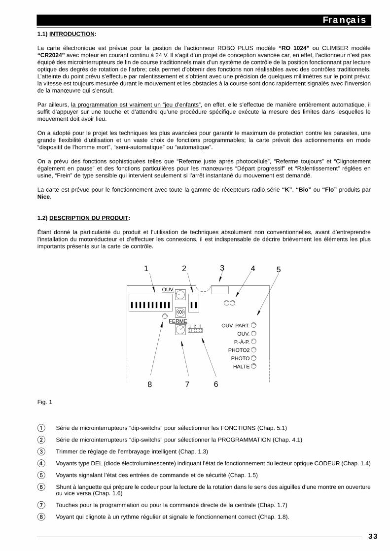
1.1) INTRODUCTION:
La carte électronique est prévue pour la gestion de l’actionneur ROBO PLUS modèle “RO 1024” ou CLIMBER modèle“CR2024” avec moteur en courant continu à 24 V. Il s’agit d’un projet de conception avancée car, en effet, l’actionneur n’est paséquipé des microinterrupteurs de fin de course traditionnels mais d’un système de contrôle de la position fonctionnant par lectureoptique des degrés de rotation de l’arbre; cela permet d’obtenir des fonctions non réalisables avec des contrôles traditionnels.L’atteinte du point prévu s’effectue par ralentissement et s’obtient avec une précision de quelques millimètres sur le point prévu;la vitesse est toujours mesurée durant le mouvement et les obstacles à la course sont donc rapidement signalés avec l’inversionde la manœuvre qui s’ensuit.
Par ailleurs, la programmation est vraiment un “jeu d’enfants”, en effet, elle s’effectue de manière entièrement automatique, ilsuffit d’appuyer sur une touche et d’attendre qu’une procédure spécifique exécute la mesure des limites dans lesquelles lemouvement doit avoir lieu.
On a adopté pour le projet les techniques les plus avancées pour garantir le maximum de protection contre les parasites, unegrande flexibilité d’utilisation et un vaste choix de fonctions programmables; la carte prévoit des actionnements en mode“dispositif de l’homme mort”, “semi-automatique” ou “automatique”.
On a prévu des fonctions sophistiquées telles que “Referme juste après photocellule”, “Referme toujours” et “Clignotementégalement en pause” et des fonctions particulières pour les manœuvres “Départ progressif” et “Ralentissement” réglées enusine, “Frein” de type sensible qui intervient seulement si l’arrêt instantané du mouvement est demandé.
La carte est prévue pour le fonctionnement avec toute la gamme de récepteurs radio série “K” , “Bio” ou “Flo” produits parNice .
1.2) DESCRIPTION DU PRODUIT:
Étant donné la particularité du produit et l’utilisation de techniques absolument non conventionnelles, avant d’entreprendrel’installation du motoréducteur et d’effectuer les connexions, il est indispensable de décrire brièvement les éléments les plusimportants présents sur la carte de contrôle.
Fig. 1
1 Série de microinterrupteurs “dip-switchs” pour sélectionner les FONCTIONS (Chap. 5.1)
2 Série de microinterrupteurs “dip-switchs” pour sélectionner la PROGRAMMATION (Chap. 4.1)
3 Trimmer de réglage de l’embrayage intelligent (Chap. 1.3)
4 Voyants type DEL (diode électroluminescente) indiquant l’état de fonctionnement du lecteur optique CODEUR (Chap. 1.4)
5 Voyants signalant l’état des entrées de commande et de sécurité (Chap. 1.5)
6 Shunt à languette qui prépare le codeur pour la lecture de la rotation dans le sens des aiguilles d’une montre en ouvertureou vice versa (Chap. 1.6)
7 Touches pour la programmation ou pour la commande directe de la centrale (Chap. 1.7)
8 Voyant qui clignote à un rythme régulier et signale le fonctionnement correct (Chap. 1.8).
Français
33
31 2
68 7
3
<<>>
21 54
OUV. PART.
OUV.
P.-À-P.
PHOTO2
PHOTO
HALTE
OUV.
FERME
1.3) Embrayage intelligent:
Le système de lecture optique de la rotation de l’arbre est utilisé principalement pour contrôler la position du portail ou de la portedurant le mouvement; à travers le même système, on peut relever également la vitesse du portail ou de la porte à chaque instant.Vu que dans un moteur en courant continu, la vitesse de rotation est pour une bonne part proportionnelle à l’effort que celui-cidoit supporter, développer un système de détection des obstacles pourrait apparaÓtre plutôt simple.Quand la vitesse descend en dessous d’une certaine limite (réglable), cela signifie qu’un effort est appliqué au-delà de la normeet qu’il y a probablement un obstacle. Une solution de ce type est influencée toutefois par d’autres facteurs qui n’ont rien à voiravec les obstacles, une banale chute de tension risquerait de faire intervenir le système, au contraire une tension supérieureprovoque un effort plus grand avant que le système intervienne.
Pour ces raisons, Nice a développé son propre système d’embrayage que nous osons qualifier “d’intelligent”.Durant le mouvement, le dispositif calcule et met à jour au fur et à mesure ce que l’on peut définir la “vitesse moyenne”. Parrapport à cette vitesse, est calculée une certaine réduction (réglable à travers le trimmer) qui représente le seuil limited’intervention. Avec cette méthode, si par exemple une chute de tension se produit, le dispositif détecte une vitesse moyenneplus basse et le seuil d’intervention se réduit donc automatiquement.Si le système d’embrayage intervient durant le mouvement, on a un arrêt effectué également avec l’aide du frein (qui enlève lapartie résiduelle d’énergie cinétique accumulée); puis si l’un des modes de fonctionnement automatique est actif, on a unemanœuvre dans le sens contraire.Dans tous les cas, pour augmenter encore davantage le niveau de sécurité, si l’embrayage intervient trois fois de suite, sansjamais atteindre l’une des conclusions naturelles du mouvement, le dispositif exécute un STOP sans inversion.
1.4) Codeur:
Le mouvement de la porte ou du portail est détecté à travers un système de contrôle de la rotation de l’arbre fonctionnant parl’intermédiaire d’une lecture optique des crans d’une roue montée dans l’arbre d’entraÓnement.Le fonctionnement correct du système de lecture peut être vérifié à travers deux DEL; quand l’arbre est mis en rotation, cesdiodes doivent clignoter au fur et à mesure que les crans sont “lus”.
1.5) Entrées:
Quand la centrale est alimentée, les voyants qui sont situés sur les entrées s’allument si l’entrée en question est active et quela tension de commande à 24 Vcc est présente. Normalement, les DEL sur les entrées des sécurités PHOTO, PHOTO2 etHALTE sont toujours allumées tandis que celles des entrées de commande PAS-À-PAS, OUVERTURE PARTIELLE ETOUVERTURE-TEMPORISATEUR sont éteintes.
1.6) Shunt pour rotation dans le sens des aiguilles d’une montre ou dans le sens contraire :
Dans la logique du motoréducteur il faut distinguer les deux manœuvres d’ouverture et de fermeture, surtout en ce qui concernel’intervention des sécurités; Photo doit intervenir principalement en fermeture tandis que Photo2 doit intervenir principalement enouverture. En usine, tous les motoréducteurs sont réglés avec rotation de l’arbre dans le sens des aiguilles d’une montre dansla manœuvre d’ouverture et dans le sens contraire dans la manœuvre de fermeture. Si besoin est, pour inverser le sens derotation, il faut inverser le connecteur du moteur mais, chose plus importante, il faut aussi “instruire” le codeur pour qu’il interprètecorrectement les impulsions qui arrivent au système de lecture optique. Cette tâche importante est exécutée à travers le shuntà languette “J8” qui peut être enlevé et réintroduit dans la position symétriquement opposée.
1.7) Touches:
Dans la phase d’installation du motoréducteur, il est souvent nécessaire de manœuvrer d’un côté ou de l’autre le portail ou laporte. La manière la plus naturelle et évidente pour le faire est de pouvoir disposer de commandes spécifiques. Les trois touches“AP”, “CH” et “<<>>” servent justement à cela: avec “AP” on active la manœuvre d’ouverture, avec “CH” on active la manœuvrede fermeture et avec “<<>>”, on augmente la vitesse du mouvement quand une phase de manœuvre lente est prévue. Ces troistouches servent dans la programmation pour la phase de mémorisation.
1.8) Del “ok” :
La DEL “OK” a pour fonction de signaler le fonctionnement correct de la logique interne: un clignotement régulier et au rythmed’1 seconde indique que le microprocesseur interne est actif et que tout est en règle. Un clignotement rapide au rythme de 5 àla seconde indique que le levier de déblocage est ouvert ou que la tension d’alimentation n’est pas suffisante, ou enfin, qu’on asélectionné une programmation incorrecte.La variation de l’état des entrées ou le déplacement d’un dip-switch provoque un double clignotement rapide.
2.1) INSTRUCTIONS POUR L’INSTALLA TION:
Effectuer l’installation physique du motoréducteur en suivant scrupuleusement toutes les indications reportées dans la noticed’instructions ci-jointe. Il faut souligner, tant par ce que la norme prEN 12453 point 5.2.1 le prévoit que parce que cela estindispensable au fonctionnement correct de la “Recherche des limites de la course” que le portail ou la porte doit être absolumentmuni/e de butées mécaniques de la course.
Français
34
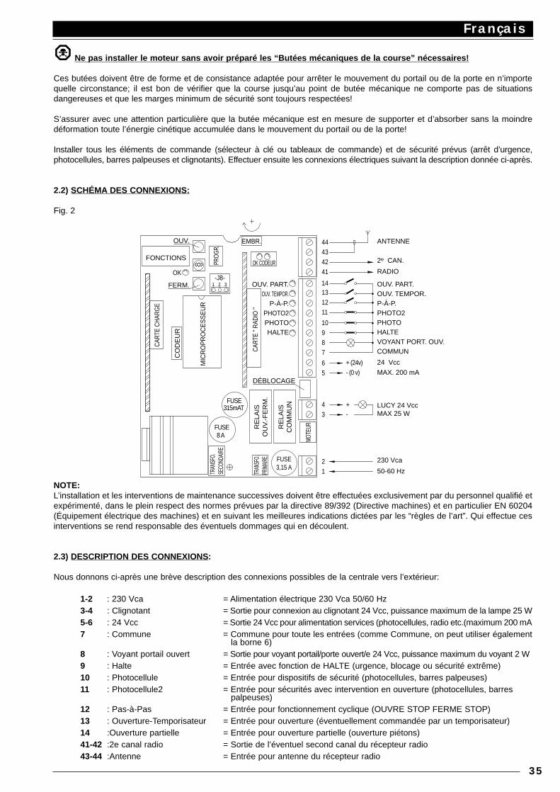
Ne pas installer le moteur sans avoir préparé les “Butées mécaniques de la course” nécessaires!
Ces butées doivent être de forme et de consistance adaptée pour arrêter le mouvement du portail ou de la porte en n’importequelle circonstance; il est bon de vérifier que la course jusqu’au point de butée mécanique ne comporte pas de situationsdangereuses et que les marges minimum de sécurité sont toujours respectées!
S’assurer avec une attention particulière que la butée mécanique est en mesure de supporter et d’absorber sans la moindredéformation toute l’énergie cinétique accumulée dans le mouvement du portail ou de la porte!
Installer tous les éléments de commande (sélecteur à clé ou tableaux de commande) et de sécurité prévus (arrêt d’urgence,photocellules, barres palpeuses et clignotants). Effectuer ensuite les connexions électriques suivant la description donnée ci-après.
2.2) SCHÉMA DES CONNEXIONS:
Fig. 2
NOTE:L’installation et les interventions de maintenance successives doivent être effectuées exclusivement par du personnel qualifié etexpérimenté, dans le plein respect des normes prévues par la directive 89/392 (Directive machines) et en particulier EN 60204(Équipement électrique des machines) et en suivant les meilleures indications dictées par les “règles de l’art”. Qui effectue cesinterventions se rend responsable des éventuels dommages qui en découlent.
2.3) DESCRIPTION DES CONNEXIONS:
Nous donnons ci-après une brève description des connexions possibles de la centrale vers l’extérieur:
1-2 : 230 Vca = Alimentation électrique 230 Vca 50/60 Hz3-4 : Clignotant = Sortie pour connexion au clignotant 24 Vcc, puissance maximum de la lampe 25 W5-6 : 24 Vcc = Sortie 24 Vcc pour alimentation services (photocellules, radio etc.(maximum 200 mA7 : Commune = Commune pour toute les entrées (comme Commune, on peut utiliser également
la borne 6)8 : Voyant portail ouvert = Sortie pour voyant portail/porte ouvert/e 24 Vcc, puissance maximum du voyant 2 W9 : Halte = Entrée avec fonction de HALTE (urgence, blocage ou sécurité extrême)10 : Photocellule = Entrée pour dispositifs de sécurité (photocellules, barres palpeuses)11 : Photocellule2 = Entrée pour sécurités avec intervention en ouverture (photocellules, barres
palpeuses)12 : Pas-à-Pas = Entrée pour fonctionnement cyclique (OUVRE STOP FERME STOP)13 : Ouverture-Temporisateur = Entrée pour ouverture (éventuellement commandée par un temporisateur)14 :Ouverture partielle = Entrée pour ouverture partielle (ouverture piétons)41-42 :2e canal radio = Sortie de l’éventuel second canal du récepteur radio43-44 :Antenne = Entrée pour antenne du récepteur radio
Français
35
MIC
RO
PR
OC
ES
SE
UR
9
CART
E CH
ARG
E
CART
E " R
ADIO
"
8 AFUSE
CO
DE
UR
FUSE315mAT
MOTE
UR
12
3
8
4
65
+ (24v)
7
- (0 v)
+-
OK CODEUR
EMBR.
OK
31 2-J8-
<<>>
OUV.
FONCTIONS
PROG
R.
11
10
41
4342
1312
14
44 ANTENNE
2e CAN.
RADIO
OUV. PART. OUV. TEMPOR. P-À-P. PHOTO2 PHOTO HALTE VOYANT PORT. OUV. COMMUN
24 Vcc
MAX. 200 mA LUCY 24 Vcc MAX 25 W
230 Vca
50-60 Hz
FERM.
TRAN
SFO.
SE
COND
AIRE
TRAN
SFO.
PR
IMAIR
E
FUSE 3,15 A
RE
LAIS
O
UV.
-FE
RM
.
RE
LAIS
C
OM
MU
N
DÉBLOCAGE
OUV. PART. OUV. TEMPOR.
P-À-P. PHOTO2 PHOTO HALTE
Les connexions restantes sont déjà effectuées en usine, pour une information complète, nous en donnons la liste:
TRANSF. PRIM. = Primaire du transformateur d’alimentationTRANSF. SEC. = Secondaire du transformateur d’alimentationMOTEUR = Sortie pour connexion moteur 24 VccDÉBLOCAGE = Microinterrupteur pour détecter l’état de moteur débloqué (manœuvre manuelle)CODEUR = Connexions au lecteur optique qui détecte la rotation de l’arbre
Il y a deux autres prises pour cartes en option:
RADIO = Prise pour récepteurs radio par NiceCHARGE = Prise pour carte chargement batterie
2.4) INSTRUCTIONS POUR LES CONNEXIONS:
Pour garantir la sécurité de l’opérateur et pour prévenir les dommages aux composants, quand on effectue les connexions, aussibien en basse tension (230 V) qu’en très basse tension (24 V) ou qu’on branche les différentes cartes:la centrale ne doit absolument pas être alimentée électriquement.
Il est conseillé d’attendre d’avoir achevé l’installation pour brancher les éventuelles cartes en option RADIO ou CHARGE etseulement après avoir vérifié le bon fonctionnement de l’installation. Les cartes en option ne sont pas nécessaires aufonctionnement et quand elles sont branchées, elles rendent plus difficile la recherche des éventuelles pannes.
Nous rappelons en outre que les entrées des contacts de type NF (Normalement fermé) doivent être shuntées si elles ne sontpas utilisées; si elles sont plus d’une, elles doivent être mises en SÉRIE. Les entrées des contacts de type NO (NormalementOuvert) doivent être laissées libres si elles ne sont pas utilisées; si elles sont plus d’une, elles doivent être mises en PARALLÈLE.En ce qui concerne les contacts, ceux-ci doivent être absolument de type mécanique et libres de toute puissance; touteconnexion à configuration de type “PNP”, “NPN”, “Open Collector” etc. est exclue.
A) Effectuer les connexions nécessaires suivant le schéma de la Fig. 1; nous rappelons qu’il y a des normes précises à respecterde manière rigoureuse tant en ce qui concerne la sécurité des installations électriques qu’en ce qui concerne les portailsautomatiques.
B) Débloquer le portail ou la porte et le positionner à mi-course, puis le bloquer; de cette manière, il peut bouger aussi bien enouverture qu’en fermeture.
Ne pas alimenter le motoréducteur sans avoir préparer les “Butées mécaniques de la course” nécessaires.
C) Alimenter la centrale en vérifiant immédiatement qu’une tension de 230 Vca arrive aux bornes 1-2 et qu’une tension de 24Vcc arrive aux bornes 5-6. Dès que la centrale est alimentée, les voyants (DEL) situés sur les entrées actives doivent s’allumer,en outre, quelques instants plus tard, la DEL “OK” devra commencer à clignoter à un rythme régulier. Si tout cela ne se produitpas, couper immédiatement l’alimentation et contrôler soigneusement les connexions.
La DEL “OK” située au centre de la carte a pour fonction de signaler l’état de la logique interne: un clignotement régulier et aurythme d’1 à la seconde indique que le microprocesseur interne est actif et en attente de commandes. Quand le microprocesseurreconnaÓt une variation de l’état d’une entrée (aussi bien entrée de commande que dip-switch des fonctions), il génère undouble clignotement rapide, même si la variation ne provoque pas d’effets immédiats. Un clignotement rapide au rythme de 5 àla seconde indique que le levier de déblocage est ouvert ou que la tension d’alimentation n’est pas suffisante, ou enfin, qu’on asélectionné une programmation incorrecte (voir Chap. 4.1).
D) Vérifier maintenant que les DEL relatives aux entrées avec contacts type NF sont allumées (toutes les sécurités sont actives)et que les DEL relatives aux entrées type NO sont éteintes (aucune commande présente), si cela ne se produit pas, contrôlerles connexions et l’efficacité des différents dispositifs.
E) Vérifier le fonctionnement correct de tous les dispositifs de sécurité présents dans l’installation (arrêt d’urgence, photocellules,barres palpeuses etc...), chaque fois qu’ils interviennent, les DEL correspondantes HALTE, PHOTO, PHOTO2 doivent s’éteindre.
Ne pas bouger le motoréducteur sans avoir préparé les “Butées mécaniques de la course” nécessaires.
F) Comme dernière opération, il faudra vérifier si le mouvement s’effectue dans le bon sens. En usine, tous les motoréducteurssont réglés avec rotation de l’arbre dans le sens des aiguilles d’une montre dans la manœuvre d’ouverture et dans le senscontraire dans la manœuvre de fermeture. Pour vérifier si le sens de rotation correspond à l’installation effectuée, il suffit depresser la touche “FERMETURE” et de vérifier si le portail ou la porte se déplace dans le sens de la fermeture.Que le sens du mouvement soit correct ou pas, il est opportun d’arrêter immédiatement la manœuvre en pressant de nouveaula touche “FERMETURE”. Puis, seulement si le mouvement ne correspond pas au sens désiré, il faut:
1 - Couper l’alimentation2 - Extraire le connecteur “MOTEUR” et le reconnecter tourné de 180°3 - Extraire le shunt sur le connecteur “J8” et le remettre dans la position symétriquement opposée
Après ces opérations, il convient d’effectuer une nouvelle tentative pour voir si le sens de rotation est correct en répétantl’opération à partir du point “F”.
NOTE: Quand on inverse le sens de manœuvre, il faut exécuter les trois opérations décrites ci-dessus. En particulier, si parexemple on tourne le connecteur “MOTEUR” sans déplacer le shunt “J8”, on provoque une erreur dans le système de lecturede rotation de l’arbre (le motoréducteur est commandé en ouverture mais le système lit un mouvement en fermeture) et dans cecas, toute tentative de mouvement est immédiatement arrêtée. Le fait se reconnaÓt également parce que les deux DEL “OK-Codeur” effectuent quelques clignotements puis le moteur s’arrête.
Français
36
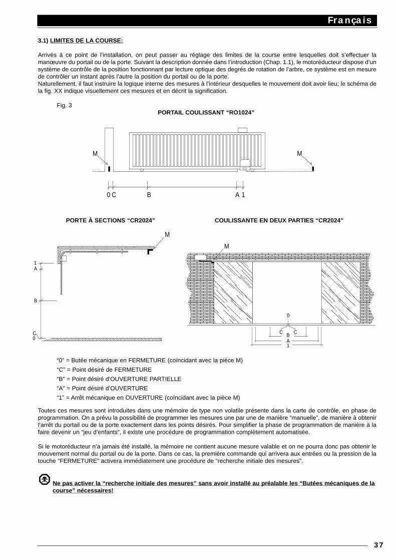
3.1) LIMITES DE LA COURSE:
Arrivés à ce point de l’installation, on peut passer au réglage des limites de la course entre lesquelles doit s’effectuer lamanœuvre du portail ou de la porte. Suivant la description donnée dans l’introduction (Chap. 1.1), le motoréducteur dispose d’unsystème de contrôle de la position fonctionnant par lecture optique des degrés de rotation de l’arbre, ce système est en mesurede contrôler un instant après l’autre la position du portail ou de la porte.Naturellement, il faut instruire la logique interne des mesures à l’intérieur desquelles le mouvement doit avoir lieu; le schéma dela fig. XX indique visuellement ces mesures et en décrit la signification.
Fig. 3PORTAIL COULISSANT “RO1024”
PORTE À SECTIONS “CR2024” COULISSANTE EN DEUX PARTIES “CR2024”
“0” = Butée mécanique en FERMETURE (coïncidant avec la pièce M)
“C” = Point désiré de FERMETURE
“B” = Point désiré d’OUVERTURE PARTIELLE
“A” = Point désiré d’OUVERTURE
“1” = Arrêt mécanique en OUVERTURE (coïncidant avec la pièce M)
Toutes ces mesures sont introduites dans une mémoire de type non volatile présente dans la carte de contrôle, en phase deprogrammation. On a prévu la possibilité de programmer les mesures une par une de manière “manuelle”, de manière à obtenirl’arrêt du portail ou de la porte exactement dans les points désirés. Pour simplifier la phase de programmation de manière à lafaire devenir un “jeu d’enfants”, il existe une procédure de programmation complètement automatisée.
Si le motoréducteur n’a jamais été installé, la mémoire ne contient aucune mesure valable et on ne pourra donc pas obtenir lemouvement normal du portail ou de la porte. Dans ce cas, la première commande qui arrivera aux entrées ou la pression de latouche “FERMETURE” activera immédiatement une procédure de “recherche initiale des mesures”.
Ne pas activer la “recherche initiale des mesures” sans avoir installé au préalable les “Butées mécaniques de lacourse” nécessaires!
Français
37
MM
0 C B A 1
M
M
1A
B
C 0
C C
0
BA1
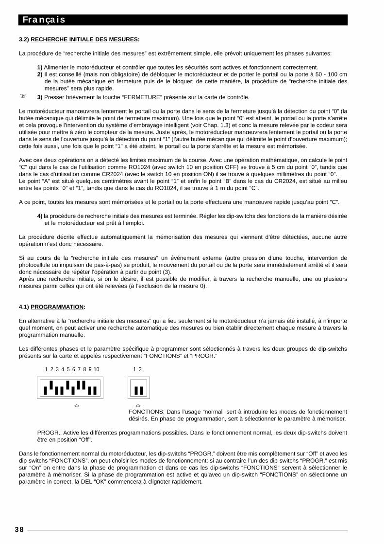
3.2) RECHERCHE INITIALE DES MESURES:
La procédure de “recherche initiale des mesures” est extrêmement simple, elle prévoit uniquement les phases suivantes:
1) Alimenter le motoréducteur et contrôler que toutes les sécurités sont actives et fonctionnent correctement.2) Il est conseillé (mais non obligatoire) de débloquer le motoréducteur et de porter le portail ou la porte à 50 - 100 cm
de la butée mécanique en fermeture puis de le bloquer; de cette manière, la procédure de “recherche initiale desmesures” sera plus rapide.
3) Presser brièvement la touche “FERMETURE” présente sur la carte de contrôle.
Le motoréducteur manœuvrera lentement le portail ou la porte dans le sens de la fermeture jusqu’à la détection du point “0” (labutée mécanique qui délimite le point de fermeture maximum). Une fois que le point “0” est atteint, le portail ou la porte s’arrêteet cela provoque l’intervention du système d’embrayage intelligent (voir Chap. 1.3) et donc la mesure relevée par le codeur serautilisée pour mettre à zéro le compteur de la mesure. Juste après, le motoréducteur manœuvrera lentement le portail ou la portedans le sens de l’ouverture jusqu’à la détection du point “1” (l’autre butée mécanique qui délimite le point d’ouverture maximum);cette fois aussi, une fois que le point “1” a été atteint, le portail ou la porte s’arrête et la mesure est mémorisée.
Avec ces deux opérations on a détecté les limites maximum de la course. Avec une opération mathématique, on calcule le point“C” qui dans le cas de l’utilisation comme RO1024 (avec switch 10 en position OFF) se trouve à 5 cm du point “0”, tandis quedans le cas d’utilisation comme CR2024 (avec le switch 10 en position ON) il se trouve à quelques millimètres du point “0”.Le point “A” est situé quelques centimètres avant le point “1” et enfin le point “B” dans le cas du CR2024, est situé au milieuentre les points “0” et “1”, tandis que dans le cas du RO1024, il se trouve à 1 m du point “C”.
A ce point, toutes les mesures sont mémorisées et le portail ou la porte effectuera une manœuvre rapide jusqu’au point “C”.
4) la procédure de recherche initiale des mesures est terminée. Régler les dip-switchs des fonctions de la manière désiréeet le motoréducteur est prêt à l’emploi.
La procédure décrite effectue automatiquement la mémorisation des mesures qui viennent d’être détectées, aucune autreopération n’est donc nécessaire.
Si au cours de la “recherche initiale des mesures” un événement externe (autre pression d’une touche, intervention dephotocellule ou impulsion de pas-à-pas) se produit, le mouvement du portail ou de la porte sera immédiatement arrêté et il seradonc nécessaire de répéter l’opération à partir du point (3).Après une recherche initiale, si on le désire, il est possible de modifier, à travers la recherche manuelle, une ou plusieursmesures parmi celles qui ont été relevées (à l’exclusion de la mesure 0).
4.1) PROGRAMMATION:
En alternative à la “recherche initiale des mesures” qui a lieu seulement si le motoréducteur n’a jamais été installé, à n’importequel moment, on peut activer une recherche automatique des mesures ou bien établir directement chaque mesure à travers laprogrammation manuelle.
Les différentes phases et le paramètre spécifique à programmer sont sélectionnés à travers les deux groupes de dip-switchsprésents sur la carte et appelés respectivement “FONCTIONS” et “PROGR.”
a aFONCTIONS: Dans l’usage “normal” sert à introduire les modes de fonctionnementdésirés. En phase de programmation, sert à sélectionner le paramètre à mémoriser.
PROGR.: Active les différentes programmations possibles. Dans le fonctionnement normal, les deux dip-switchs doiventêtre en position “Off”.
Dans le fonctionnement normal du motoréducteur, les dip-switchs “PROGR.” doivent être mis complètement sur “Off” et avec lesdip-switchs “FONCTIONS”, on peut choisir les modes de fonctionnement; si au contraire l’un des dip-switchs “PROGR.” est missur “On” on entre dans la phase de programmation et dans ce cas les dip-switchs “FONCTIONS” servent à sélectionner leparamètre à mémoriser. Si la phase de programmation est active et qu’avec un dip-switch “FONCTIONS” on sélectionne unparamètre in correct, la DEL “OK” commencera à clignoter rapidement.
Français
38
1 2 3 4 5 6 7 8 9 10 1 2
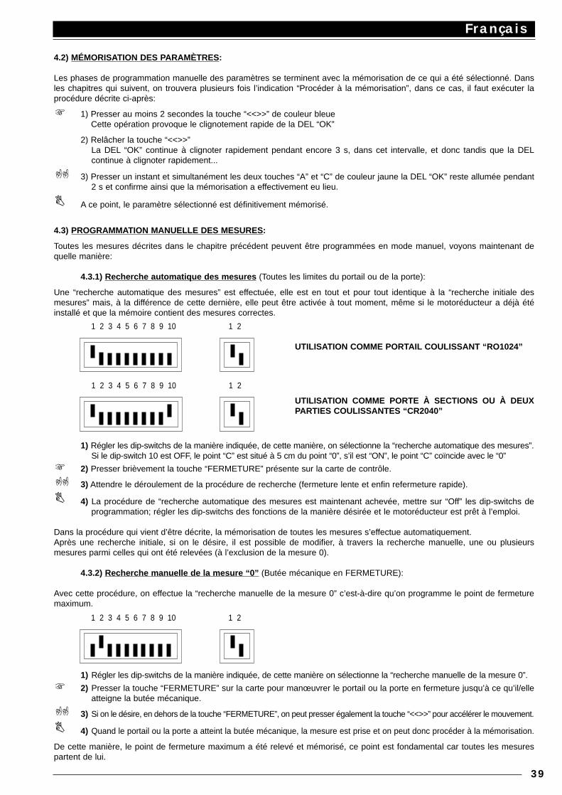
4.2) MÉMORISATION DES PARAMÈTRES:
Les phases de programmation manuelle des paramètres se terminent avec la mémorisation de ce qui a été sélectionné. Dansles chapitres qui suivent, on trouvera plusieurs fois l’indication “Procéder à la mémorisation”, dans ce cas, il faut exécuter laprocédure décrite ci-après:
1) Presser au moins 2 secondes la touche “<<>>” de couleur bleueCette opération provoque le clignotement rapide de la DEL “OK”
2) Relâcher la touche “<<>>”La DEL “OK” continue à clignoter rapidement pendant encore 3 s, dans cet intervalle, et donc tandis que la DELcontinue à clignoter rapidement...
3) Presser un instant et simultanément les deux touches “A” et “C” de couleur jaune la DEL “OK” reste allumée pendant2 s et confirme ainsi que la mémorisation a effectivement eu lieu.
A ce point, le paramètre sélectionné est définitivement mémorisé.
4.3) PROGRAMMATION MANUELLE DES MESURES :
Toutes les mesures décrites dans le chapitre précédent peuvent être programmées en mode manuel, voyons maintenant dequelle manière:
4.3.1) Recherche automatique des mesures (Toutes les limites du portail ou de la porte):
Une “recherche automatique des mesures” est effectuée, elle est en tout et pour tout identique à la “recherche initiale desmesures” mais, à la différence de cette dernière, elle peut être activée à tout moment, même si le motoréducteur a déjà étéinstallé et que la mémoire contient des mesures correctes.
1) Régler les dip-switchs de la manière indiquée, de cette manière, on sélectionne la “recherche automatique des mesures”.Si le dip-switch 10 est OFF, le point “C” est situé à 5 cm du point “0”, s’il est “ON”, le point “C” coïncide avec le “0”
2) Presser brièvement la touche “FERMETURE” présente sur la carte de contrôle.
3) Attendre le déroulement de la procédure de recherche (fermeture lente et enfin refermeture rapide).
4) La procédure de “recherche automatique des mesures est maintenant achevée, mettre sur “Off” les dip-switchs deprogrammation; régler les dip-switchs des fonctions de la manière désirée et le motoréducteur est prêt à l’emploi.
Dans la procédure qui vient d’être décrite, la mémorisation de toutes les mesures s’effectue automatiquement.Après une recherche initiale, si on le désire, il est possible de modifier, à travers la recherche manuelle, une ou plusieursmesures parmi celles qui ont été relevées (à l’exclusion de la mesure 0).
4.3.2) Recherche manuelle de la mesure “0” (Butée mécanique en FERMETURE):
Avec cette procédure, on effectue la “recherche manuelle de la mesure 0” c’est-à-dire qu’on programme le point de fermeturemaximum.
1) Régler les dip-switchs de la manière indiquée, de cette manière on sélectionne la “recherche manuelle de la mesure 0”.
2) Presser la touche “FERMETURE” sur la carte pour manœuvrer le portail ou la porte en fermeture jusqu’à ce qu’il/elleatteigne la butée mécanique.
3) Si on le désire, en dehors de la touche “FERMETURE”, on peut presser également la touche “<<>>” pour accélérer le mouvement.
4) Quand le portail ou la porte a atteint la butée mécanique, la mesure est prise et on peut donc procéder à la mémorisation.
De cette manière, le point de fermeture maximum a été relevé et mémorisé, ce point est fondamental car toutes les mesurespartent de lui.
Français
39
1 2 3 4 5 6 7 8 9 10 1 2
1 2 3 4 5 6 7 8 9 10 1 2
UTILISATION COMME PORTAIL COULISSANT “RO1024”
UTILISATION COMME PORTE À SECTIONS OU À DEUXPARTIES COULISSANTES “CR2040”
1 2 3 4 5 6 7 8 9 10 1 2
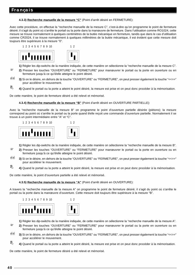
4.3.3) Recherche manuelle de la mesure “C” (Point d’arrêt désiré en FERMETURE):
Avec cette procédure, on effectue la “recherche manuelle de la mesure C”, c’est-à-dire qu’on programme le point de fermeturedésiré; il s’agit du point où s’arrête le portail ou la porte dans la manœuvre de fermeture. Dans l’utilisation comme RO1024, cettemesure se trouve normalement à quelques centimètres de la butée mécanique en fermeture, tandis que dans le cas d’utilisationcomme CR2024, il se trouve normalement à quelques millimètres de la butée mécanique, il est évident que cette mesure doittoujours être supérieure à la mesure “0”.
1) Régler les dip-switchs de la manière indiquée, de cette manière on sélectionne la “recherche manuelle de la mesure C”.
2) Presser les touches “OUVERTURE” ou “FERMETURE” pour manœuvrer le portail ou la porte en ouverture ou enfermeture jusqu’à ce qu’il/elle atteigne le point désiré.
3) Si on le désire, en dehors de la touche “OUVERTURE” ou “FERMETURE”, on peut presser également la touche “<<>>”pour accélérer le mouvement.
4) Quand le portail ou la porte a atteint le point désiré, la mesure est prise et on peut donc procéder à la mémorisation.
De cette manière, le point de fermeture désiré a été relevé et mémorisé.
4.3.4) Recherche manuelle de la mesure “B” (Point d’arrêt désiré en OUVERTURE PARTIELLE):
Avec la “recherche manuelle de la mesure B” on programme le point d’ouverture partielle désirée (piétons); la mesurecorrespond au point où s’arrête le portail ou la porte quand il/elle reçoit une commande d’ouverture partielle. Normalement il setrouve à un point intermédiaire entre “A” et “C”.
1) Régler les dip-switchs de la manière indiquée, de cette manière on sélectionne la “recherche manuelle de la mesure B”.
2) Presser les touches “OUVERTURE” ou “FERMETURE” pour manœuvrer le portail ou la porte en ouverture ou enfermeture jusqu’à ce qu’il/elle atteigne le point désiré.
3) Si on le désire, en dehors de la touche “OUVERTURE” ou “FERMETURE”, on peut presser également la touche “<<>>”pour accélérer le mouvement.
4) Quand le portail ou la porte a atteint le point désiré, la mesure est prise et on peut donc procéder à la mémorisation.
De cette manière, le point d’ouverture partielle a été relevé et mémorisé.
4.3.5) Recherche manuelle de la mesure “A” (Point d’arrêt désiré en OUVERTURE):
A travers la “recherche manuelle de la mesure A” on programme le point de fermeture désiré; il s’agit du point où s’arrête leportail ou la porte dans la manœuvre d’ouverture. Cette mesure doit toujours être supérieure à la mesure “B”.
1) Régler les dip-switchs de la manière indiquée, de cette manière on sélectionne la “recherche manuelle de la mesure A”.
2) Presser les touches “OUVERTURE” ou “FERMETURE” pour manœuvrer le portail ou la porte en ouverture ou enfermeture jusqu’à ce qu’il/elle atteigne le point désiré.
3) Si on le désire, en dehors de la touche “OUVERTURE” ou “FERMETURE”, on peut presser également la touche “<<>>”pour accélérer le mouvement.
4) Quand le portail ou la porte a atteint le point désiré, la mesure est prise et on peut donc procéder à la mémorisation.
De cette manière, le point de fermeture désiré a été relevé et mémorisé.
Français
40
1 2 3 4 5 6 7 8 9 10 1 2
1 2 3 4 5 6 7 8 9 10 1 2
1 2 3 4 5 6 7 8 9 10 1 2
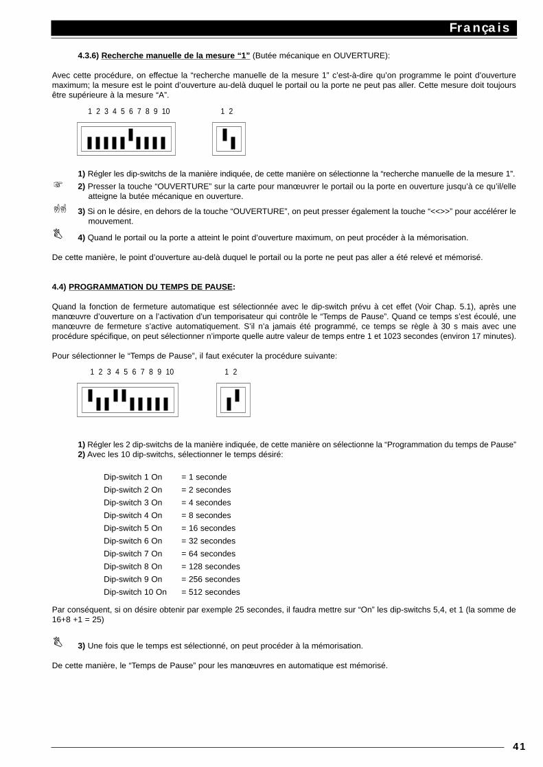
4.3.6) Recherche manuelle de la mesure “1” (Butée mécanique en OUVERTURE):
Avec cette procédure, on effectue la “recherche manuelle de la mesure 1” c’est-à-dire qu’on programme le point d’ouverturemaximum; la mesure est le point d’ouverture au-delà duquel le portail ou la porte ne peut pas aller. Cette mesure doit toujoursêtre supérieure à la mesure “A”.
1) Régler les dip-switchs de la manière indiquée, de cette manière on sélectionne la “recherche manuelle de la mesure 1”.
2) Presser la touche “OUVERTURE” sur la carte pour manœuvrer le portail ou la porte en ouverture jusqu’à ce qu’il/elleatteigne la butée mécanique en ouverture.
3) Si on le désire, en dehors de la touche “OUVERTURE”, on peut presser également la touche “<<>>” pour accélérer lemouvement.
4) Quand le portail ou la porte a atteint le point d’ouverture maximum, on peut procéder à la mémorisation.
De cette manière, le point d’ouverture au-delà duquel le portail ou la porte ne peut pas aller a été relevé et mémorisé.
4.4) PROGRAMMATION DU TEMPS DE PAUSE:
Quand la fonction de fermeture automatique est sélectionnée avec le dip-switch prévu à cet effet (Voir Chap. 5.1), après unemanœuvre d’ouverture on a l’activation d’un temporisateur qui contrôle le “Temps de Pause”. Quand ce temps s’est écoulé, unemanœuvre de fermeture s’active automatiquement. S’il n’a jamais été programmé, ce temps se règle à 30 s mais avec uneprocédure spécifique, on peut sélectionner n’importe quelle autre valeur de temps entre 1 et 1023 secondes (environ 17 minutes).
Pour sélectionner le “Temps de Pause”, il faut exécuter la procédure suivante:
1) Régler les 2 dip-switchs de la manière indiquée, de cette manière on sélectionne la “Programmation du temps de Pause”2) Avec les 10 dip-switchs, sélectionner le temps désiré:
Dip-switch 1 On = 1 seconde
Dip-switch 2 On = 2 secondes
Dip-switch 3 On = 4 secondes
Dip-switch 4 On = 8 secondes
Dip-switch 5 On = 16 secondes
Dip-switch 6 On = 32 secondes
Dip-switch 7 On = 64 secondes
Dip-switch 8 On = 128 secondes
Dip-switch 9 On = 256 secondes
Dip-switch 10 On = 512 secondes
Par conséquent, si on désire obtenir par exemple 25 secondes, il faudra mettre sur “On” les dip-switchs 5,4, et 1 (la somme de16+8 +1 = 25)
3) Une fois que le temps est sélectionné, on peut procéder à la mémorisation.
De cette manière, le “Temps de Pause” pour les manœuvres en automatique est mémorisé.
Français
41
1 2 3 4 5 6 7 8 9 10 1 2
1 2 3 4 5 6 7 8 9 10 1 2
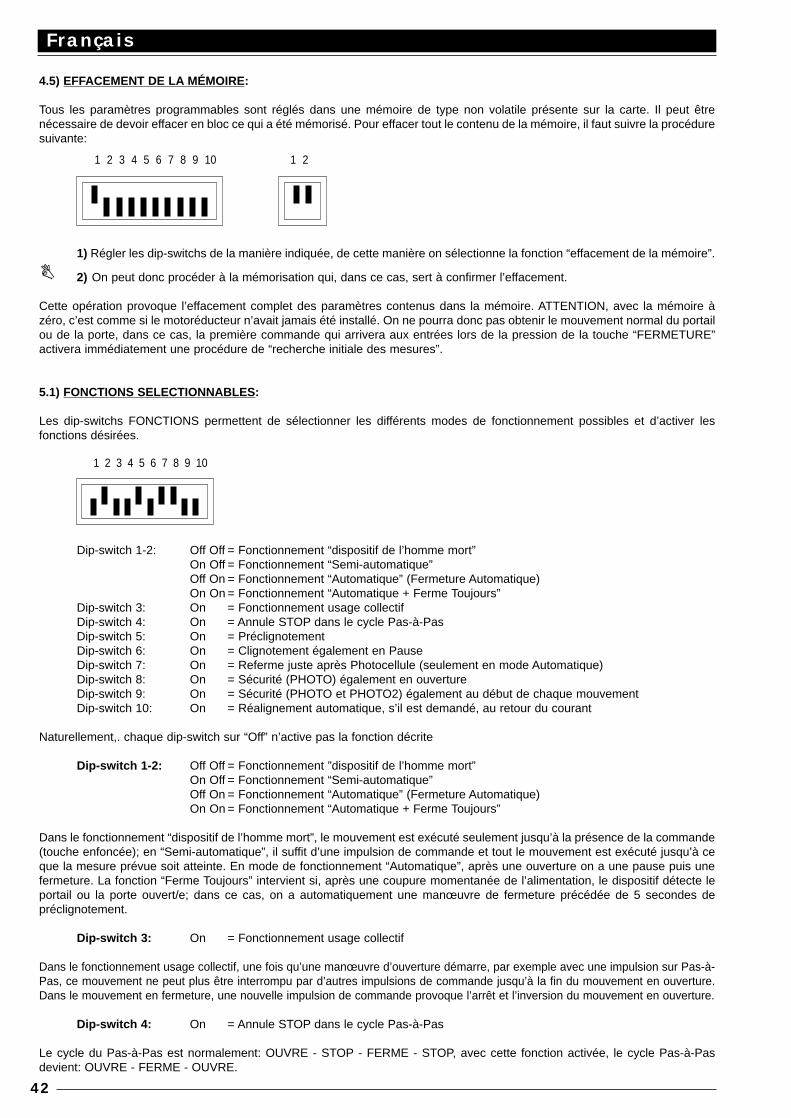
4.5) EFFACEMENT DE LA MÉMOIRE:
Tous les paramètres programmables sont réglés dans une mémoire de type non volatile présente sur la carte. Il peut êtrenécessaire de devoir effacer en bloc ce qui a été mémorisé. Pour effacer tout le contenu de la mémoire, il faut suivre la procéduresuivante:
1) Régler les dip-switchs de la manière indiquée, de cette manière on sélectionne la fonction “effacement de la mémoire”.
2) On peut donc procéder à la mémorisation qui, dans ce cas, sert à confirmer l’effacement.
Cette opération provoque l’effacement complet des paramètres contenus dans la mémoire. ATTENTION, avec la mémoire àzéro, c’est comme si le motoréducteur n’avait jamais été installé. On ne pourra donc pas obtenir le mouvement normal du portailou de la porte, dans ce cas, la première commande qui arrivera aux entrées lors de la pression de la touche “FERMETURE”activera immédiatement une procédure de “recherche initiale des mesures”.
5.1) FONCTIONS SELECTIONNABLES :
Les dip-switchs FONCTIONS permettent de sélectionner les différents modes de fonctionnement possibles et d’activer lesfonctions désirées.
Dip-switch 1-2: Off Off = Fonctionnement “dispositif de l’homme mort”On Off = Fonctionnement “Semi-automatique”Off On = Fonctionnement “Automatique” (Fermeture Automatique)On On = Fonctionnement “Automatique + Ferme Toujours”
Dip-switch 3: On = Fonctionnement usage collectifDip-switch 4: On = Annule STOP dans le cycle Pas-à-PasDip-switch 5: On = PréclignotementDip-switch 6: On = Clignotement également en PauseDip-switch 7: On = Referme juste après Photocellule (seulement en mode Automatique)Dip-switch 8: On = Sécurité (PHOTO) également en ouvertureDip-switch 9: On = Sécurité (PHOTO et PHOTO2) également au début de chaque mouvementDip-switch 10: On = Réalignement automatique, s’il est demandé, au retour du courant
Naturellement,. chaque dip-switch sur “Off” n’active pas la fonction décrite
Dip-switch 1-2: Off Off = Fonctionnement ”dispositif de l’homme mort”On Off = Fonctionnement “Semi-automatique”Off On = Fonctionnement “Automatique” (Fermeture Automatique)On On = Fonctionnement “Automatique + Ferme Toujours”
Dans le fonctionnement “dispositif de l’homme mort”, le mouvement est exécuté seulement jusqu’à la présence de la commande(touche enfoncée); en “Semi-automatique”, il suffit d’une impulsion de commande et tout le mouvement est exécuté jusqu’à ceque la mesure prévue soit atteinte. En mode de fonctionnement “Automatique”, après une ouverture on a une pause puis unefermeture. La fonction “Ferme Toujours” intervient si, après une coupure momentanée de l’alimentation, le dispositif détecte leportail ou la porte ouvert/e; dans ce cas, on a automatiquement une manœuvre de fermeture précédée de 5 secondes depréclignotement.
Dip-switch 3: On = Fonctionnement usage collectif
Dans le fonctionnement usage collectif, une fois qu’une manœuvre d’ouverture démarre, par exemple avec une impulsion sur Pas-à-Pas, ce mouvement ne peut plus être interrompu par d’autres impulsions de commande jusqu’à la fin du mouvement en ouverture.Dans le mouvement en fermeture, une nouvelle impulsion de commande provoque l’arrêt et l’inversion du mouvement en ouverture.
Dip-switch 4: On = Annule STOP dans le cycle Pas-à-Pas
Le cycle du Pas-à-Pas est normalement: OUVRE - STOP - FERME - STOP, avec cette fonction activée, le cycle Pas-à-Pasdevient: OUVRE - FERME - OUVRE.
Français
42
1 2 3 4 5 6 7 8 9 10 1 2
1 2 3 4 5 6 7 8 9 10
Dip-switch 5: On = Préclignotement
L’impulsion de commande provoque d’abord l’activation du clignotant puis après 5 secondes (2 s en mode manuel), lemouvement commence.
Dip-switch 6: On = Clignotement également en Pause
Normalement, le clignotant est activé seulement durant le mouvement en ouverture ou en fermeture, cette fonction prévoit quele clignotant reste actif même durant la Pause, afin de signaler l’état de “fermeture prochaine”.
Dip-switch 7: On = Referme juste après Photocellule (seulement en mode Automatique: D-Sw.2=On)
Cette fonction permet de garder le portail ou la porte ouvert/e seulement le temps nécessaire au passage; en effet, la fermetureautomatique aura lieu toujours 5 secondes après le dégagement de la photocellule, indépendamment du Temps de Pauseprogrammé.
Dip-switch 8: On = Sécurité (PHOTO) également en ouverture
Normalement, la sécurité “Photo.” intervient seulement dans la manœuvre de fermeture, si le dip-switch N°8 est mis sur “On”,l’intervention du dispositif de sécurité provoque une interruption du mouvement également en ouverture; en mode Semi-Automatique ou Automatique, on aura la reprise du mouvement en ouverture juste après le dégagement de la photocellule.
Dip-switch 9: On = Sécurité (PHOTO et PHOTO 2) également au début de chaque mouvement
Habituellement, la sécurité “Photo” intervient seulement durant la manœuvre de fermeture et “Photo2” intervient seulementdurant la manœuvre d’ouverture. Si l’on désire augmenter le niveau de sécurité, avant de commencer le mouvement, on peutvérifier l’accord de la part des sécurités “Photo” et “Photo2” puis, seulement après, commencer le mouvement.
Dip-switch 10: On = Réalignement automatique, s’il est demandé, au retour du courant
En présence d’une interruption du courant et quand le portail ou la porte est débloqué/e, le système de lecture de la position duportail ou de la porte perd la mesure; dans cette éventualité, on a prévu une procédure de “Réalignement” qui consiste àrechercher de nouveau le point “C”. La procédure de réalignement est effectuée normalement après le retour du courant, quandla première impulsion de commande arrive. Avec le dip-switch N°10 sur “On”, le réalignement a lieu dès que le courant revientet sans attendre d’impulsions de commande.
6.1) ESSAI DE FONCTIONNEMENT:
Après avoir vérifié les connexions (Chap. 2.4) et effectué la programmation des limites de la course (Chap. 3.2 ou 4.3.1), on peutessayer le mouvement de l’actionneur; il est conseillé d’opérer en mode “dispositif de l’homme mort” avec toutes les fonctionsdésactivées (tous les dip-switchs sur Off). En toute circonstance, en mode “dispositif de l’homme mort”, quand on relâche la touchede commande on obtient l’arrêt immédiat du moteur. Si on utilise comme commande l’entrée Pas-à-Pas, le premier mouvement (aprèsl’allumage) devra être en ouverture. Dans cette phase, il résulte particulièrement commode d’utiliser les touches “AP” (ouverture). “CH”(fermeture) qui se trouvent sur la carte. En agissant sur les entrées de commande, manœuvrer le portail ou la porte jusqu’au pointdésiré d’ouverture “A”, environ 20 cm avant le point d’arrêt on doit avoir la phase de “ralentissement” qui permet d’atteindre le pointprévu à une vitesse réduite à environ 30%. Exécuter ensuite un mouvement en fermeture jusqu’au point de fermeture “C” désiré; dansce cas également, la phase de ralentissement devra intervenir 20 cm avant l’arrêt du mouvement. Essayer ensuite de provoquerl’intervention des dispositifs de sécurité. “PHOTO” en ouverture n’a aucun effet, en fermeture cette sécurité provoque l’arrêt dumouvement; “PHOTO2” en fermeture n’a aucun effet, en ouverture elle provoque l’arrêt du mouvement. Les dispositifs connectés àl’entrée HALTE agissent aussi bien en ouverture qu’en fermeture en provoquant toujours l’arrêt du mouvement.
Les récentes normes européennes - prEN 12453: sécurité dans l’emploi des portes motorisées - conditions requises etclassifications; prEN 12445: sécurité dans l’emploi des portes motorisées - méthodes d’essai (pas encore définitivementapprouvées mais qui le seront courant 1998) - demandent l’utilisation de mesures pour limiter les forces en jeu dans lemouvement des portes automatiques égales à un maximum de 1400 N comme force d’impact ainsi qu’une force résiduellestatique maximum de 150 N qui doit ensuite s’annuler dans les 5 secondes qui suivent l’impact.Ce résultat s’obtient à travers le réglage de l’embrayage électronique intelligent. Il y a sur la carte un trimmer EMBRAYAGE quipermet de déterminer le seuil d’intervention de l’embrayage.
Comme le décrit le chapitre 1.3, le système d’embrayage intelligent opère des calculs afin d’obtenir la vitesse moyenne du mouvementet donc d’intervenir avec plus de précision. Pour évaluer l’effet du réglage sur le trimmer, il est donc préférable d’attendre que lemouvement ait commencé et que le portail ou la porte ait atteint la vitesse standard. Faire attention aussi au fait que, toujours pourdes questions de sécurité, si l’embrayage intervient pendant trois fois de suite, le mouvement est arrêté sans effectuer l’inversion.
Si l’on a sélectionné le mode automatique, à la fin de la manœuvre d’ouverture, on a une “pause” à la fin de laquelle est lancéeautomatiquement une manœuvre de fermeture. Le temps de pause, s’il n’a pas été programmé avec la procédure spécifique,est égal à 30 secondes.
La pause est activée également dans le mouvement en semi-automatique quand, en fermeture, l’intervention d’un dispositif desécurité ou de l’embrayage intelligent provoque une inversion en ouverture.
Ce n’est qu’à ce moment, à la fin de tous les réglages et sans que la centrale soit alimentée, que nous conseillons de brancherle récepteur radio.
Français
43
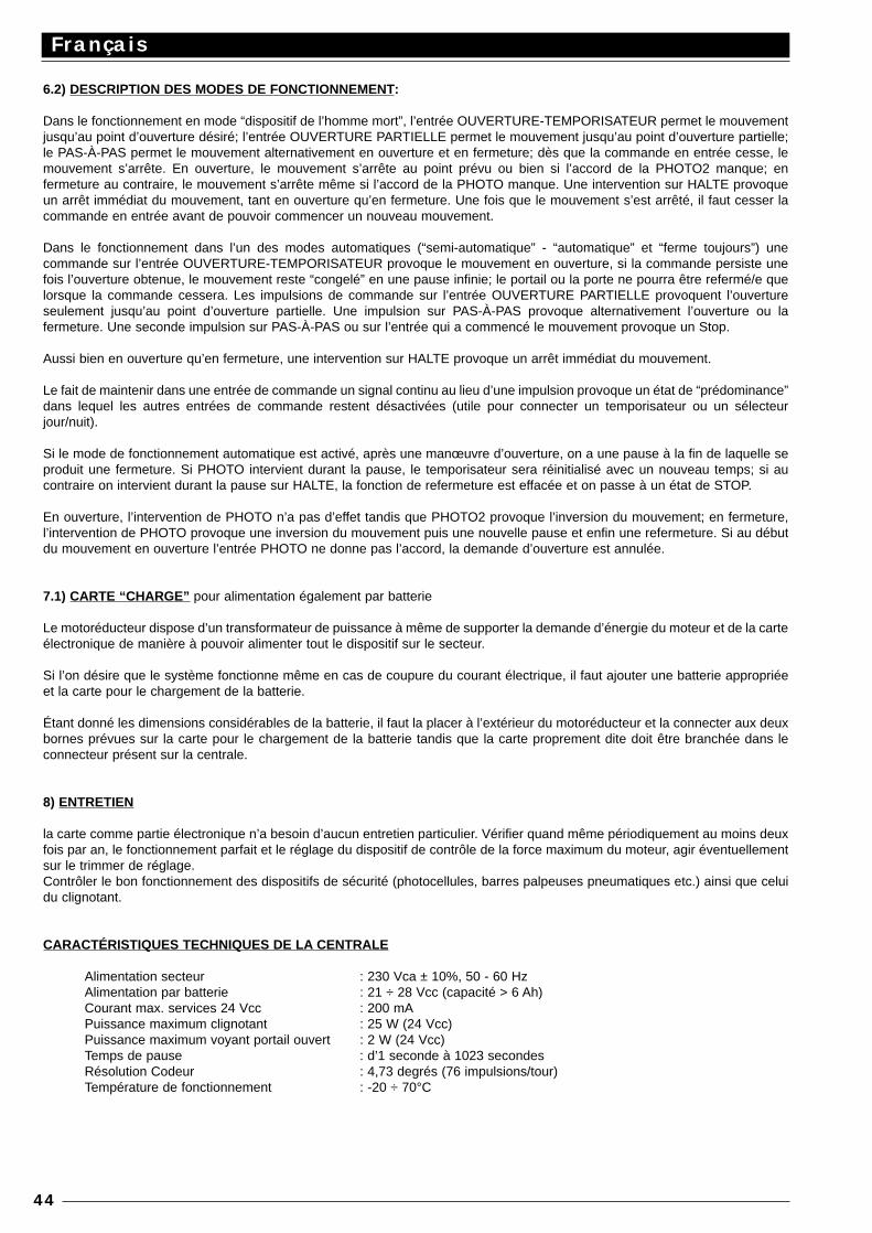
6.2) DESCRIPTION DES MODES DE FONCTIONNEMENT:
Dans le fonctionnement en mode “dispositif de l’homme mort”, l’entrée OUVERTURE-TEMPORISATEUR permet le mouvementjusqu’au point d’ouverture désiré; l’entrée OUVERTURE PARTIELLE permet le mouvement jusqu’au point d’ouverture partielle;le PAS-À-PAS permet le mouvement alternativement en ouverture et en fermeture; dès que la commande en entrée cesse, lemouvement s’arrête. En ouverture, le mouvement s’arrête au point prévu ou bien si l’accord de la PHOTO2 manque; enfermeture au contraire, le mouvement s’arrête même si l’accord de la PHOTO manque. Une intervention sur HALTE provoqueun arrêt immédiat du mouvement, tant en ouverture qu’en fermeture. Une fois que le mouvement s’est arrêté, il faut cesser lacommande en entrée avant de pouvoir commencer un nouveau mouvement.
Dans le fonctionnement dans l’un des modes automatiques (“semi-automatique” - “automatique” et “ferme toujours”) unecommande sur l’entrée OUVERTURE-TEMPORISATEUR provoque le mouvement en ouverture, si la commande persiste unefois l’ouverture obtenue, le mouvement reste “congelé” en une pause infinie; le portail ou la porte ne pourra être refermé/e quelorsque la commande cessera. Les impulsions de commande sur l’entrée OUVERTURE PARTIELLE provoquent l’ouvertureseulement jusqu’au point d’ouverture partielle. Une impulsion sur PAS-À-PAS provoque alternativement l’ouverture ou lafermeture. Une seconde impulsion sur PAS-À-PAS ou sur l’entrée qui a commencé le mouvement provoque un Stop.
Aussi bien en ouverture qu’en fermeture, une intervention sur HALTE provoque un arrêt immédiat du mouvement.
Le fait de maintenir dans une entrée de commande un signal continu au lieu d’une impulsion provoque un état de “prédominance”dans lequel les autres entrées de commande restent désactivées (utile pour connecter un temporisateur ou un sélecteurjour/nuit).
Si le mode de fonctionnement automatique est activé, après une manœuvre d’ouverture, on a une pause à la fin de laquelle seproduit une fermeture. Si PHOTO intervient durant la pause, le temporisateur sera réinitialisé avec un nouveau temps; si aucontraire on intervient durant la pause sur HALTE, la fonction de refermeture est effacée et on passe à un état de STOP.
En ouverture, l’intervention de PHOTO n’a pas d’effet tandis que PHOTO2 provoque l’inversion du mouvement; en fermeture,l’intervention de PHOTO provoque une inversion du mouvement puis une nouvelle pause et enfin une refermeture. Si au débutdu mouvement en ouverture l’entrée PHOTO ne donne pas l’accord, la demande d’ouverture est annulée.
7.1) CARTE “CHARGE” pour alimentation également par batterie
Le motoréducteur dispose d’un transformateur de puissance à même de supporter la demande d’énergie du moteur et de la carteélectronique de manière à pouvoir alimenter tout le dispositif sur le secteur.
Si l’on désire que le système fonctionne même en cas de coupure du courant électrique, il faut ajouter une batterie appropriéeet la carte pour le chargement de la batterie.
Étant donné les dimensions considérables de la batterie, il faut la placer à l’extérieur du motoréducteur et la connecter aux deuxbornes prévues sur la carte pour le chargement de la batterie tandis que la carte proprement dite doit être branchée dans leconnecteur présent sur la centrale.
8) ENTRETIEN
la carte comme partie électronique n’a besoin d’aucun entretien particulier. Vérifier quand même périodiquement au moins deuxfois par an, le fonctionnement parfait et le réglage du dispositif de contrôle de la force maximum du moteur, agir éventuellementsur le trimmer de réglage.Contrôler le bon fonctionnement des dispositifs de sécurité (photocellules, barres palpeuses pneumatiques etc.) ainsi que celuidu clignotant.
CARACTÉRISTIQUES TECHNIQUES DE LA CENTRALE
Alimentation secteur : 230 Vca ± 10%, 50 - 60 HzAlimentation par batterie : 21 ÷ 28 Vcc (capacité > 6 Ah)Courant max. services 24 Vcc : 200 mAPuissance maximum clignotant : 25 W (24 Vcc)Puissance maximum voyant portail ouvert : 2 W (24 Vcc)Temps de pause : d’1 seconde à 1023 secondesRésolution Codeur : 4,73 degrés (76 impulsions/tour)Température de fonctionnement : -20 ÷ 70°C
Français
44
Deutsch
45
Dieses Handbuch ist nur für Techniker bestimmt, die für die Installation qualifiziert sind.Für den Endbenutzer ist keine der in diesem Band enthaltenen Informationen von W ichtigkeit!
INHALT:
Schnellanleitung : 46Einleitung : 47
Beschreibung des Produktes : 47Installationsanleitungen : 49
Schaltplan : 49Beschreibung der Anschlüsse : 50Anleitungen für die Ausführung der Anschlüsse : 51
Laufgrenzen : 52Anfängliche Suche nach den Maßen : 53
Programmierung : 53Speicherung der Parameter : 54Manuelle Programmierung der Maße : 54Programmierung der Pausezeit : 56Löschen der Speicherungen : 57
Wählbare Funktionen : 57Betriebstest : 58Beschreibung der Betriebsarten : 59“LADE”-Karte für Batteriespeisung : 59Warttung : 59Technische Merkmale der Zentrale : 60
WICHTIG:
Es ist unsere Pflicht, Sie daran zu erinnern, dass Sie Arbeiten an Maschinenanlagen ausführen, die in die Kategorie der“automatischen Tore und Türen” eingeordnet worden sind und daher als besonders “Gefährlich” betrachtet werden: Ihre Aufgabeist es, diese so weit wie möglich sicher zu machen!Die Installation und eventuelle Wartungsarbeiten dürfen nur von erfahrenem Fachpersonal ausgeführt werden, das die besten,fachgemässen Anweisungen zu befolgen und in Übereinstimmung mit den Verordnungen der folgenden Gesetze, Normen oderRichtlinien vorzugehen hat:
89/392 CEE (Maschinenrichtlinie) 89/336 CEE (Richtlinie über die Elektromagnetische Kompatibilität) 73/23 CEE (Richtlinie für Niederspannung)PrEN 12453 (Sicherheit beim Gebrauch der motorisierten Türen - Requisiten und Klassifizierungen)PrEN 12445 (Sicherheit beim Gebrauch der motorisierten Türen - Testmethoden)
Bei der Projektierung und Konstruktion ihrer Produkte beachtet Nice (was die Apparaturen betrifft) all diese Vorschriften, es istjedoch grundlegend, dass die gleichen Normen auch vom Installateur (was die Anlagen betrifft) mit der gleichen Genauigkeit undSorgfalt beachtet werden.
Personal, das kein Fachpersonal ist oder die für die Kategorie “Automatische Tore und Türen” anwendbaren Vorschriften nichtkennt,
darf absolut keine Installationen und Anlagen ausführen.
Wer Anlagen ausführt, ohne die anwendbaren Vorschriften zu beachten:haftet für eventuelle Schäden, welche die Anlage verursachen kann!
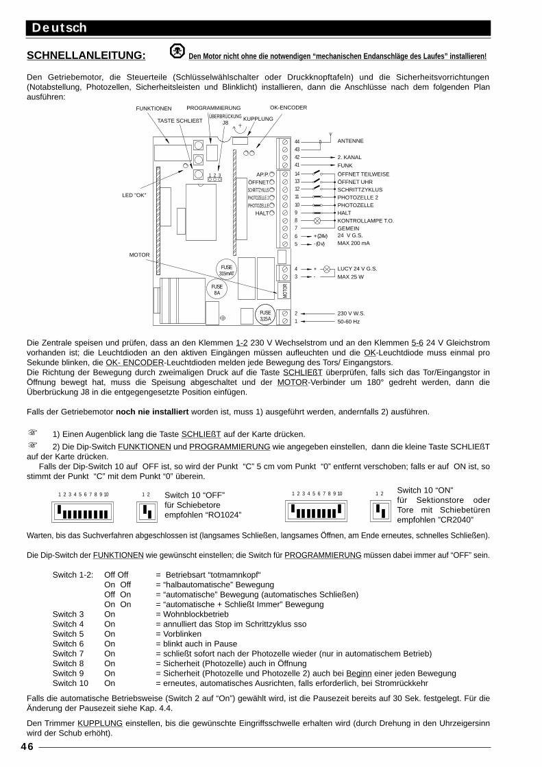
SCHNELLANLEITUNG: Den Motor nicht ohne die notwendigen “mechanischen Endanschläge des Laufes” installieren!
Den Getriebemotor, die Steuerteile (Schlüsselwählschalter oder Druckknopftafeln) und die Sicherheitsvorrichtungen(Notabstellung, Photozellen, Sicherheitsleisten und Blinklicht) installieren, dann die Anschlüsse nach dem folgenden Planausführen:
Die Zentrale speisen und prüfen, dass an den Klemmen 1-2 230 V Wechselstrom und an den Klemmen 5-6 24 V Gleichstromvorhanden ist; die Leuchtdioden an den aktiven Eingängen müssen aufleuchten und die OK-Leuchtdiode muss einmal proSekunde blinken, die OK- ENCODER-Leuchtdioden melden jede Bewegung des Tors/ Eingangstors.Die Richtung der Bewegung durch zweimaligen Druck auf die Taste SCHLIEßT überprüfen, falls sich das Tor/Eingangstor inÖffnung bewegt hat, muss die Speisung abgeschaltet und der MOTOR-Verbinder um 180° gedreht werden, dann dieÜberbrückung J8 in die entgegengesetzte Position einfügen.
Falls der Getriebemotor noch nie installiert worden ist, muss 1) ausgeführt werden, andernfalls 2) ausführen.
1) Einen Augenblick lang die Taste SCHLIEßT auf der Karte drücken.
2) Die Dip-Switch FUNKTIONEN und PROGRAMMIERUNG wie angegeben einstellen, dann die kleine Taste SCHLIEßTauf der Karte drücken.
Falls der Dip-Switch 10 auf OFF ist, so wird der Punkt “C” 5 cm vom Punkt “0” entfernt verschoben; falls er auf ON ist, sostimmt der Punkt “C” mit dem Punkt “0” überein.
Warten, bis das Suchverfahren abgeschlossen ist (langsames Schließen, langsames Öffnen, am Ende erneutes, schnelles Schließen).
Die Dip-Switch der FUNKTIONEN wie gewünscht einstellen; die Switch für PROGRAMMIERUNG müssen dabei immer auf “OFF” sein.
Switch 1-2: Off Off = Betriebsart “totmamnkopf“On Off = “halbautomatische” BewegungOff On = “automatische” Bewegung (automatisches Schließen)On On = “automatische + Schließt Immer” Bewegung
Switch 3 On = WohnblockbetriebSwitch 4 On = annulliert das Stop im Schrittzyklus sso Switch 5 On = VorblinkenSwitch 6 On = blinkt auch in PauseSwitch 7 On = schließt sofort nach der Photozelle wieder (nur in automatischem Betrieb)Switch 8 On = Sicherheit (Photozelle) auch in ÖffnungSwitch 9 On = Sicherheit (Photozelle und Photozelle 2) auch bei Beginn einer jeden Bewegung Switch 10 On = erneutes, automatisches Ausrichten, falls erforderlich, bei Stromrückkehr
Falls die automatische Betriebsweise (Switch 2 auf “On”) gewählt wird, ist die Pausezeit bereits auf 30 Sek. festgelegt. Für dieÄnderung der Pausezeit siehe Kap. 4.4.
Den Trimmer KUPPLUNG einstellen, bis die gewünschte Eingriffsschwelle erhalten wird (durch Drehung in den Uhrzeigersinnwird der Schub erhöht).
Deutsch
46
- (0 v)
MOTOR
8 A
315mAT
FUSE
FUSE
1
MOT
OR
FUSE3,15 A
2
34 +
-
LED "OK"
FUNKTIONEN
31 2
ÜBERBRÜCKUNG J8
PROGRAMMIERUNG
TASTE SCHLIEßT
98
65
+ (24v)
7
11
10
1312
14
41
4342
44
KUPPLUNG
OK-ENCODER
ANTENNE
2. KANAL
FUNK
ÖFFNET TEILWEISE ÖFFNET UHR SCHRITTZYKLUS PHOTOZELLE 2 PHOTOZELLE HALT KONTROLLAMPE T.O. GEMEIN 24 V G.S. MAX 200 mA
LUCY 24 V G.S.
MAX 25 W
230 V W.S.
50-60 Hz
AP.P. ÖFFNET SCHRITTZYKLUS PHOTOZELLE 2 PHOTOZELLE
HALT
1 2 3 4 5 6 7 8 9 10 1 2 1 2 3 4 5 6 7 8 9 10 1 2Switch 10 “OFF”für Schiebetoreempfohlen “RO1024”
Switch 10 “ON”für Sektionstore oderTore mit Schiebetürenempfohlen ”CR2040”
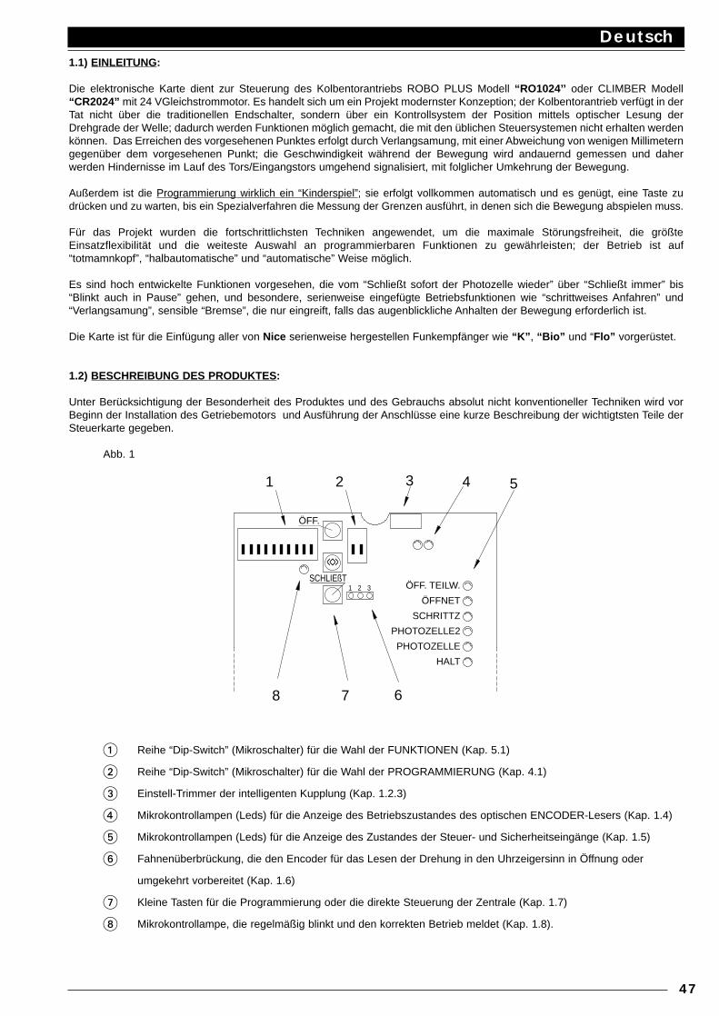
1.1) EINLEITUNG:
Die elektronische Karte dient zur Steuerung des Kolbentorantriebs ROBO PLUS Modell “RO1024’’ oder CLIMBER Modell“CR2024” mit 24 VGleichstrommotor. Es handelt sich um ein Projekt modernster Konzeption; der Kolbentorantrieb verfügt in derTat nicht über die traditionellen Endschalter, sondern über ein Kontrollsystem der Position mittels optischer Lesung derDrehgrade der Welle; dadurch werden Funktionen möglich gemacht, die mit den üblichen Steuersystemen nicht erhalten werdenkönnen. Das Erreichen des vorgesehenen Punktes erfolgt durch Verlangsamung, mit einer Abweichung von wenigen Millimeterngegenüber dem vorgesehenen Punkt; die Geschwindigkeit während der Bewegung wird andauernd gemessen und daherwerden Hindernisse im Lauf des Tors/Eingangstors umgehend signalisiert, mit folglicher Umkehrung der Bewegung.
Außerdem ist die Programmierung wirklich ein “Kinderspiel”; sie erfolgt vollkommen automatisch und es genügt, eine Taste zudrücken und zu warten, bis ein Spezialverfahren die Messung der Grenzen ausführt, in denen sich die Bewegung abspielen muss.
Für das Projekt wurden die fortschrittlichsten Techniken angewendet, um die maximale Störungsfreiheit, die größteEinsatzflexibilität und die weiteste Auswahl an programmierbaren Funktionen zu gewährleisten; der Betrieb ist auf“totmamnkopf”, “halbautomatische” und “automatische” Weise möglich.
Es sind hoch entwickelte Funktionen vorgesehen, die vom “Schließt sofort der Photozelle wieder” über “Schließt immer” bis“Blinkt auch in Pause” gehen, und besondere, serienweise eingefügte Betriebsfunktionen wie “schrittweises Anfahren” und“Verlangsamung”, sensible “Bremse”, die nur eingreift, falls das augenblickliche Anhalten der Bewegung erforderlich ist.
Die Karte ist für die Einfügung aller von Nice serienweise hergestellen Funkempfänger wie “K” , “Bio” und “Flo” vorgerüstet.
1.2) BESCHREIBUNG DES PRODUKTES :
Unter Berücksichtigung der Besonderheit des Produktes und des Gebrauchs absolut nicht konventioneller Techniken wird vorBeginn der Installation des Getriebemotors und Ausführung der Anschlüsse eine kurze Beschreibung der wichtigtsten Teile derSteuerkarte gegeben.
Abb. 1
1 Reihe “Dip-Switch” (Mikroschalter) für die Wahl der FUNKTIONEN (Kap. 5.1)
2 Reihe “Dip-Switch” (Mikroschalter) für die Wahl der PROGRAMMIERUNG (Kap. 4.1)
3 Einstell-Trimmer der intelligenten Kupplung (Kap. 1.2.3)
4 Mikrokontrollampen (Leds) für die Anzeige des Betriebszustandes des optischen ENCODER-Lesers (Kap. 1.4)
5 Mikrokontrollampen (Leds) für die Anzeige des Zustandes der Steuer- und Sicherheitseingänge (Kap. 1.5)
6 Fahnenüberbrückung, die den Encoder für das Lesen der Drehung in den Uhrzeigersinn in Öffnung oder
umgekehrt vorbereitet (Kap. 1.6)
7 Kleine Tasten für die Programmierung oder die direkte Steuerung der Zentrale (Kap. 1.7)
8 Mikrokontrollampe, die regelmäßig blinkt und den korrekten Betrieb meldet (Kap. 1.8).
Deutsch
47
31 2
68 7
3
<<>>
21 54
ÖFF.
SCHLIEßTÖFF. TEILW.
ÖFFNET
SCHRITTZ
PHOTOZELLE2
PHOTOZELLE
HALT
1.3) Intelligente Kupplung :
Das optische Lesungssystem der Wellendrehung wird hauptsächlich benutzt, um die Position des Tors/Eingangstors währendder Bewegung zu kontrollieren; mit dem gleichen System kann auch die Geschwindigkeit des Tors/Eingangstors in jedemAugenblick gemessen werden.Da die Drehgeschwindigkeit eines Gleichstrommotors großteils proportional zur Beanspruchung ist, die der Motor aushaltenmuss, könnte die Entwicklung eines Systems für die Wahrnehmung der Hinternisse ziemlich einfach erscheinen. Wenn dieGeschwindigkeit unter einen (einstellbaren) Grenzwert sinkt, bedeutet das, dass eine Beanspruchung vorhanden ist, die größerals üblich ist, und dass daher wahrscheinlich ein Hindernis vorhanden ist. Eine Lösung dieser Art wird jedoch durch andereFaktoren beeinflußt, die nichts mit dem Hindernis zu tun haben; auch durch einen banalen Spannungsschwund könnte dasSystem eingreifen, auf der anderen Seite verursacht eine höhere Spannung eine größere Beanspruchung, bevor das Systemeingreifen kann.Aus diesem Grund hat Nice ihr eigenes Kupplungssystem entwickelt, das wir als “intelligent” zu definieren wagen.Während der Bewegung wird nach und nach die Geschwindigkeit, die als “Durchschnittsgeschwindigkeit” definiert werdenkönnte, berechnet und auf den neuesten Stand gebracht; im Vergleich zu dieser Geschwindigkeit wird eine gewisseReduzierung (durch den Trimmer einstellbar) berechnet, welche die Eingriffsgrenzschwelle darstellt. Falls mit dieser Methode zum Beispiel ein Spannungsschwund eintreten sollte, würde eine niedrigereDurchschnittsgeschwindigkeit festgestellt und automatisch würde auch die Eingriffsschwelle herabgesetzt. Falls das Kupplungssystem während der Bewegung eingreift, wird ein Anhalten auch mit Hilfe der Bremse ausgeführt (welchedie angesammelte, kinetische Restenergie beseitigt); falls dann eine der automatischen Betriebsarten aktiv ist, wird eineBewegung in die umgekehrte Richtung gestartet.Um den Sicherheitsgrad noch weiter zu erhöhen, erfolgt ein STOP ohne Umkehrung, falls die Kupplung dreimal nacheinandereingreift, ohne jemals eines der natürlichen Enden der Bewegung zu erreichen.
1.4) Encoder :
Die Bewegung des Tors/Eingangstors wird durch ein Kontrollsystem der Drehung der Welle gemessen, das mittels optischerLesung der Kerben auf einem Wellenrad funktioniert.Der korrekte Betrieb des Lesungssystems kann mit zwei Leuchtdioden überprüft werden; wenn die Welle in Drehung gebrachtwird, müssen die Leuchtdioden während des Lesens der Kerben blinken.
1.5) Eingänge :
Wenn die Zentrale gespeist ist, leuchten die Kontrollampen an den jeweiligen Eingängen auf, wenn der betreffende Eingang aktivund daher die 24 V G.S. Steuerspannung vorhanden ist. Gewöhnlich sind die Leuchtdioden an den Eingängen der SicherheitenPHOTOZELLE, PHOTOZELLE2 und HALT immer eingeschaltet, wogegen jene an den Eingängen der SteuerungenSCHRITTZYKLUS, ÖFFNET TEILWEISE und ÖFFNET-UHR gewöhnlich ausgeschaltet sind.
1.6) Überbrückung für die Drehung in oder gegen den Uhrzeigersinn :
Vor allem was den Eingriff der Sicherheiten betrifft, muss in der Logik des Getriebemotors zwischen den zwei Vorgängen Öffnenund Schließen unterschieden werden. Photozelle muss vor allem während des Schließens eingreifen, Photozelle 2 dagegen vorallem während des Öffnens. Während ihrer Herstellung werden alle Getriebemotoren mit Wellendrehung in den Uhrzeigersinnin Öffnung, und gegen den Uhrzeigersinn in Schließung vorbereitet. Falls nötig, muss für die Änderung des Drehsinns derMotorverbinder umgekehrt werden, und - noch wichtiger - dem Encoder müssen “Anweisungen” gegeben werden, damit er dieImpulse, die vom optischen Lesungssystem kommen, richtig ausdeuten kann. Diese wichtige Aufgabe wird von derFahnenüberbrückung “J8” ausgeführt, die herausgezogen und in die spiegelbildlich entgegengesetzte Position eingesetztwerden kann.
1.7) Kleine T asten :
Während der Installation des Getriebemotors muss das Tor/Eingangstor oft auf die eine oder andere Seite bewegt werden; dieeinfachste und offensichtlichste Methode ist, dazu bestimmte Steuerungen zur Verfügung zu haben. Die drei kleinen Tasten “AP”,“CH” und “<<>>” dienen zu diesem Zweck; mit “AP” wird die Öffnungsbewegung aktiviert, mit “CH” die Schließbewegung undmit “<<>>” wird die Geschwindigkeit der Bewegung während einer langsamen Bewegungsphase beschleunigt. Die drei kleinenTasten dienen auch bei der Programmierung zur Speicherung.
1.8) “OK”-Leuchtdiode :
Die “OK”-Leuchtdiode hat die Aufgabe, den korrekten Betrieb der internen Logik zu melden: ein regelmäßiges Blinken einmalpro Sekunde bedeutet, dass der interne Mikroprozessor aktiv und alles in Ordnung ist. Ein schnelles Blinken fünfmal proSekunde bedeutet, dass der Entriegelungshebel geöffnet oder dass keine ausreichende Speisungsspannung vorhanden ist, oderdass eine unkorrekte Programmierung gewählt worden ist.Ein doppeltes Schnellblinken erfolgt, wenn eine Änderung des Zustandes der Eingänge besteht oder ein Dip-Switch verstelltwird.
Deutsch
48
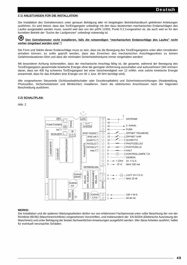
2.1) ANLEITUNGEN FÜR DIE INSTALLA TION:
Die Installation des Getriebemotors unter genauer Befolgung aller im beigelegten Betriebshandbuch gelieferten Anleitungenausführen. Es wird betont, dass das Tor/Eingangstor unbedingt mit den dazu bestimmten mechanischen Endanschlägen desLaufes ausgestattet werden muss, sowohl weil das von der prEN 12453, Punkt 5.2.1vorgesehen ist, als auch weil es für denkorrekten Betrieb der “Suche der Laufgrenzen” unbedingt notwendig ist.
Den Getriebemotor nicht installieren, falls die notwendigen “mechanischen Endanschläge des Laufes” nichtvorher eingebaut worden sind “!
Die Form und Stärke dieser Endanschläge muss so sein, dass sie die Bewegung des Tors/Eingangstors unter allen Umständenanhalten können; es sollte geprüft werden, dass das Erreichen des mechanischen Anschlagpunktes zu keinenGefahrensituationen führt und dass die minimalen Sicherheitsfreiräume immer eingehalten werden!
Mit besonderer Achtung sicherstellen, dass der mechanische Anschlag fähig ist, die gesamte, während der Bewegung desTors/Eingangstors gesammelte kinetische Energie ohne die geringste Verformung auszuhalten und aufzunehmen! (Wir erinnerndaran, dass ein 400 Kg schweres Tor/Eingangstor bei einer Geschwindigkeit von 12 m/Min. eine solche kinetische Energieansammelt, dass für das Anhalten eine Energie von 40 J, bzw. 40 N/m benötigt wird).
Alle vorgesehenen Steuerteile (Schlüsselwählschalter oder Druckknopftafeln) und Sicherheitsvorrichtungen (Notabstellung,Photozellen, Sicherheitsleisten und Blinklichter) installieren. Dann die elektrischen Anschlüssen nach der folgendenBeschreibung ausführen.
2.2) SCHALTPLAN:
Abb. 2
MERKE:Die Installation und die späteren Wartungsarbeiten dürfen nur von erfahrenem Fachpersonal unter voller Beachtung der von derRichtlinie 89/392 (Maschinenrichtlinie) vorgesehenen Vorschriften, und insbesondere der EN 60204 (Elektrische Ausrüstung derMaschinen) und unter Befolgung der besten fachwerklichen Anweisungen ausgeführt werden. Wer diese Arbeiten ausführt, haftetfür eventuell verursachte Schäden.
Deutsch
49
MIK
RO
PR
OZ
ES
SO
R
9
LAD
EK
AR
TE
FU
NK
KA
RT
E
8 ASICHERUNG
CO
DE
UR
SICHERUNG315mAT
MO
TOR
12
3
8
4
65
+ (24v)
7
- (0 v)
+-
OK-ENCODER
KUPPL.
OK
31 2-J8-
<<>>
ÖFF.
FUNKTIONEN
PROG
R.
11
10
41
4342
1312
14
44
SCHLIEßT
SICHERUNG 3,15 A
ENTRIEGELUNG
ANTENNE
2. KANAL
FUNK
ÖFFNET TEILWEISE
ÖFFNET UHR
SCHRITTZ.
PHOTOZELLE2
PHOTOZELLE
HALT
KONTROLLAMPE T.O.
GEMEIN
24 V G.S.
MAX 200 mA
LUCY 24 V G.S.
MAX 25 W
230 V W.S.
50-60 Hz
SEKU
NDÄ
TRAN
SFORM
ATOR
PRIM
ÄR
TRANSF
ORMATO
RR
ELA
IS
ÖF
F.-S
CH
LIE
ßT
GE
ME
INS
AM
ES
R
ELA
IS
ÖFFNET TEILWEISE
ÖFFNET UHR
SCHRITTZ.
PHOTOZELLE2
PHOTOZELLE
HALT
2.3) BESCHREIBUNG DER ANSCHLÜSSE:
Hier folgend wir eine kurze Beschreibung der möglichen Anschlüsse der Zentrale nach außen gegeben:
1-2 : 230 Vac = elektrische 230 V W.S. Speisung, 50/60 Hz
3-4 : Blinklicht = Ausgang für den Anschluss an das 24 V GS Blinklicht, Höchstleistung der Lampe 25 W
5-6 : 24 Vcc = 24 V GS Ausgang für die Speisung der Zubehörteile (Photozelle, Funksteuerung, usw.),maximal 200 mA
7 : Gemeinsam = Gemein für alle Eingänge (als Gemeinsamer kann auch die Klemme 6 benutzt werden)
8 : Kontrollampe T.O. = Ausgang für die 24 V G.S. Kontrollampe für Tor/Eingangstor Offen, Höchstleistung der Kontrollampe 2 W
9 : Halt = Eingang mit Halt-Funktion (Notabstellung, Verriegelung oder extreme Sicherheit)
10 : Photozelle = Eingang für Sicherheitsvorrichtungen (Photozellen, Sicherheitsleisten)
11 : Photozelle 2 = Eingang für Sicherheitsvorrichtungen mit Eingriff in Öffnung (Photozellen,Sicherheitsleisten)
12 : Schrittzyklus = Eingang für zyklischen Betrieb (ÖFFNET-STOP-SCHLIEßT-STOP)
13 : Öffnet-Uhr = Eingang für die Öffnung (eventuell durch Uhrwerk gesteuert)
14 : Öffnet Teilweise = Eingang für teilweise Öffnung (für Fußgänger)
41-42 : 2. Funkkanal = Ausgang des eventuellen, zweiten Kanals des Funkempfängers
43-44 : Antenne = Eingang für die Antenne des Funkempfängers
Die restlichen Anschlüsse werden bereits im Herstellerwerk ausgeführt, zur Vollständigkeit geben wir sie hier an:
PRIM.TRANSF. = Primärwicklung des Speisetransformators
SEKUND.TRANSF. = Sekundärwicklung des Speisetransformators
MOTOR = Ausgang für den Anschluss des 24 V G.S. Motors
ENTRIEG. = Mikroschalter für das Vermessen des entriegelten Motors (Handbetrieb)
ENCODER = Anschlüsse zum optischen Leser für die Messung der Wellendrehung
Für Sonderkarten stehen zwei weitere Steckvorrichtungen zur Verfügung:
FUNK = Steckvorrichtung für die von Nice hergestellten Funkempfänger
LADEGERÄT = Steckvorrichtung für die Karte des Batterieladegeräts
Deutsch
50
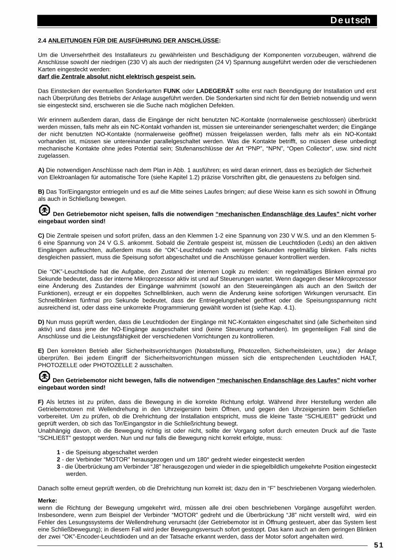
2.4 ANLEITUNGEN FÜR DIE AUSFÜHRUNG DER ANSCHLÜSSE:
Um die Unversehrtheit des Installateurs zu gewährleisten und Beschädigung der Komponenten vorzubeugen, während dieAnschlüsse sowohl der niedrigen (230 V) als auch der niedrigsten (24 V) Spannung ausgeführt werden oder die verschiedenenKarten eingesteckt werden:darf die Zentrale absolut nicht elektrisch gespeist sein.
Das Einstecken der eventuellen Sonderkarten FUNK oder LADEGERÄT sollte erst nach Beendigung der Installation und erstnach Überprüfung des Betriebs der Anlage ausgeführt werden. Die Sonderkarten sind nicht für den Betrieb notwendig und wennsie eingesteckt sind, erschweren sie die Suche nach möglichen Defekten.
Wir erinnern außerdem daran, dass die Eingänge der nicht benutzten NC-Kontakte (normalerweise geschlossen) überbrücktwerden müssen, falls mehr als ein NC-Kontakt vorhanden ist, müssen sie untereinander seriengeschaltet werden; die Eingängeder nicht benutzten NO-Kontakte (normalerweise geöffnet) müssen freigelassen werden, falls mehr als ein NO-Kontaktvorhanden ist, müssen sie untereinander parallelgeschaltet werden. Was die Kontakte betrifft, so müssen diese unbedingtmechanische Kontakte ohne jedes Potential sein; Stufenanschlüsse der Art “PNP”, “NPN”, “Open Collector”, usw. sind nichtzugelassen.
A) Die notwendigen Anschlüsse nach dem Plan in Abb. 1 ausführen; es wird daran erinnert, dass es bezüglich der Sicherheit von Elektroanlagen für automatische Tore (siehe Kapitel 1.2) präzise Vorschriften gibt, die genauestens zu befolgen sind.
B) Das Tor/Eingangstor entriegeln und es auf die Mitte seines Laufes bringen; auf diese Weise kann es sich sowohl in Öffnung als auch in Schließung bewegen.
Den Getriebemotor nicht speisen, falls die notwendigen “mechanischen Endanschläge des Laufes” nicht vorhereingebaut worden sind!
C) Die Zentrale speisen und sofort prüfen, dass an den Klemmen 1-2 eine Spannung von 230 V W.S. und an den Klemmen 5-6 eine Spannung von 24 V G.S. ankommt. Sobald die Zentrale gespeist ist, müssen die Leuchtdioden (Leds) an den aktivenEingängen aufleuchten, außerdem muss die “OK”-Leuchtdiode nach wenigen Sekunden regelmäßig blinken. Falls nichtsdesgleichen passiert, muss die Speisung sofort abgeschaltet und die Anschlüsse genauer kontrolliert werden.
Die “OK”-Leuchtdiode hat die Aufgabe, den Zustand der internen Logik zu melden: ein regelmäßiges Blinken einmal proSekunde bedeutet, dass der interne Mikroprozessor aktiv ist und auf Steuerungen wartet. Wenn dagegen dieser Mikroprozessoreine Änderung des Zustandes der Eingänge wahrnimmt (sowohl an den Steuereingängen als auch an den Switch derFunktionen), erzeugt er ein doppeltes Schnellblinken, auch wenn die Änderung keine sofortigen Wirkungen verursacht. EinSchnellblinken fünfmal pro Sekunde bedeutet, dass der Entriegelungshebel geöffnet oder die Speisungsspannung nichtausreichend ist, oder dass eine unkorrekte Programmierung gewählt worden ist (siehe Kap. 4.1).
D) Nun muss geprüft werden, dass die Leuchtdioden der Eingänge mit NC-Kontakten eingeschaltet sind (alle Sicherheiten sindaktiv) und dass jene der NO-Eingänge ausgeschaltet sind (keine Steuerung vorhanden). Im gegenteiligen Fall sind dieAnschlüsse und die Leistungsfähigkeit der verschiedenen Vorrichtungen zu kontrollieren.
E) Den korrekten Betrieb aller Sicherheitsvorrichtungen (Notabstellung, Photozellen, Sicherheitsleisten, usw.) der Anlageüberprüfen. Bei jedem Eingriff der Sicherheitsvorrichtungen müssen sich die entsprechenden Leuchtdioden HALT,PHOTOZELLE oder PHOTOZELLE 2 ausschalten.
Den Getriebemotor nicht bewegen, falls die notwendigen “mechanischen Endanschläge des Laufes” nicht vorhereingebaut worden sind!
F) Als letztes ist zu prüfen, dass die Bewegung in die korrekte Richtung erfolgt. Während ihrer Herstellung werden alleGetriebemotoren mit Wellendrehung in den Uhrzeigersinn beim Öffnen, und gegen den Uhrzeigersinn beim Schließenvorbereitet. Um zu prüfen, ob die Drehrichtung der Installation entspricht, muss die kleine Taste “SCHLIEßT” gedrückt undgeprüft werden, ob sich das Tor/Eingangstor in die Schließrichtung bewegt.Unabhängig davon, ob die Bewegung richtig ist oder nicht, sollte der Vorgang sofort durch erneuten Druck auf die Taste“SCHLIEßT” gestoppt werden. Nun und nur falls die Bewegung nicht korrekt erfolgte, muss:
1 - die Speisung abgeschaltet werden2 - der Verbinder “MOTOR” herausgezogen und um 180° gedreht wieder eingesteckt werden3 - die Überbrückung am Verbinder “J8” herausgezogen und wieder in die spiegelbildlich umgekehrte Position eingesteckt
werden.
Danach sollte erneut geprüft werden, ob die Drehrichtung nun korrekt ist; dazu den in “F” beschriebenen Vorgang wiederholen.
Merke:wenn die Richtung der Bewegung umgekehrt wird, müssen alle drei oben beschriebenen Vorgänge ausgeführt werden.Insbesondere, wenn zum Beispiel der Verbinder “MOTOR” gedreht und die Überbrückung “J8” nicht verstellt wird, wird einFehler des Lesungssystems der Wellendrehung verursacht (der Getriebemotor ist in Öffnung gesteuert, aber das System liesteine Schließbewegung); in diesem Fall wird jeder Bewegungsversuch sofort gestoppt. Das kann auch an dem geringen Blinkender zwei “OK”-Encoder-Leuchtdioden und an der Tatsache erkannt werden, dass der Motor sofort angehalten wird.
Deutsch
51
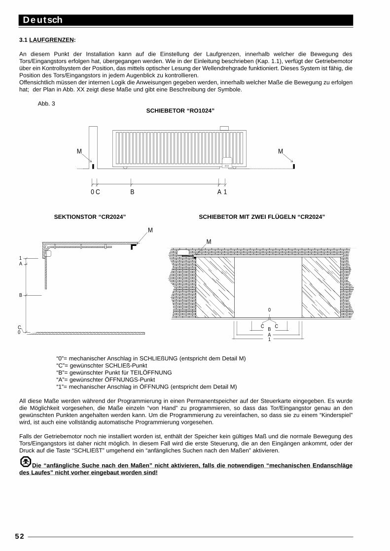
3.1 LAUFGRENZEN:
An diesem Punkt der Installation kann auf die Einstellung der Laufgrenzen, innerhalb welcher die Bewegung desTors/Eingangstors erfolgen hat, übergegangen werden. Wie in der Einleitung beschrieben (Kap. 1.1), verfügt der Getriebemotorüber ein Kontrollsystem der Position, das mittels optischer Lesung der Wellendrehgrade funktioniert. Dieses System ist fähig, diePosition des Tors/Eingangstors in jedem Augenblick zu kontrollieren.Offensichtlich müssen der internen Logik die Anweisungen gegeben werden, innerhalb welcher Maße die Bewegung zu erfolgenhat; der Plan in Abb. XX zeigt diese Maße und gibt eine Beschreibung der Symbole.
Abb. 3SCHIEBETOR “RO1024”
SEKTIONSTOR “CR2024” SCHIEBETOR MIT ZWEI FLÜGELN “CR2024”
“0”= mechanischer Anschlag in SCHLIEßUNG (entspricht dem Detail M)“C”= gewünschter SCHLIEß-Punkt“B”= gewünschter Punkt für TEILÖFFNUNG“A”= gewünschter ÖFFNUNGS-Punkt“1”= mechanischer Anschlag in ÖFFNUNG (entspricht dem Detail M)
All diese Maße werden während der Programmierung in einen Permanentspeicher auf der Steuerkarte eingegeben. Es wurdedie Möglichkeit vorgesehen, die Maße einzeln “von Hand” zu programmieren, so dass das Tor/Eingangstor genau an dengewünschten Punkten angehalten werden kann. Um die Programmierung zu vereinfachen, so dass sie zu einem “Kinderspiel”wird, ist auch eine vollständig automatische Programmierung vorgesehen.
Falls der Getriebemotor noch nie installiert worden ist, enthält der Speicher kein gültiges Maß und die normale Bewegung desTors/Eingangstors ist daher nicht möglich. In diesem Fall wird die erste Steuerung, die an den Eingängen ankommt, oder derDruck auf die Taste “SCHLIEßT” umgehend ein “anfängliches Suchen nach den Maßen” aktivieren.
Die “anfängliche Suche nach den Maßen” nicht aktivieren, falls die notwendigen “mechanischen Endanschlägedes Laufes” nicht vorher eingebaut worden sind!
Deutsch
52
MM
0 C B A 1
M
M
1A
B
C 0
C C
0
BA1
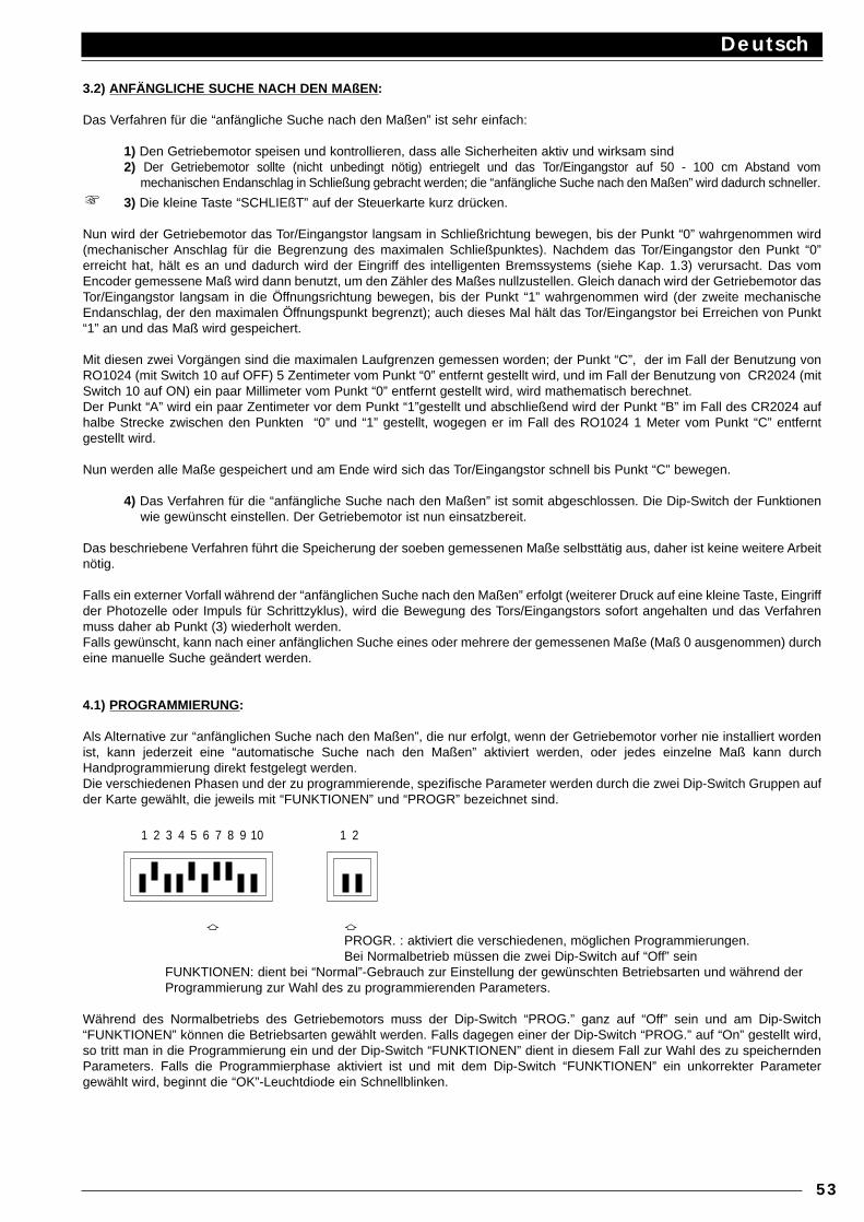
3.2) ANFÄNGLICHE SUCHE NACH DEN MAßEN :
Das Verfahren für die “anfängliche Suche nach den Maßen” ist sehr einfach:
1) Den Getriebemotor speisen und kontrollieren, dass alle Sicherheiten aktiv und wirksam sind2) Der Getriebemotor sollte (nicht unbedingt nötig) entriegelt und das Tor/Eingangstor auf 50 - 100 cm Abstand vom
mechanischen Endanschlag in Schließung gebracht werden; die “anfängliche Suche nach den Maßen” wird dadurch schneller.
3) Die kleine Taste “SCHLIEßT” auf der Steuerkarte kurz drücken.
Nun wird der Getriebemotor das Tor/Eingangstor langsam in Schließrichtung bewegen, bis der Punkt “0” wahrgenommen wird(mechanischer Anschlag für die Begrenzung des maximalen Schließpunktes). Nachdem das Tor/Eingangstor den Punkt “0”erreicht hat, hält es an und dadurch wird der Eingriff des intelligenten Bremssystems (siehe Kap. 1.3) verursacht. Das vomEncoder gemessene Maß wird dann benutzt, um den Zähler des Maßes nullzustellen. Gleich danach wird der Getriebemotor dasTor/Eingangstor langsam in die Öffnungsrichtung bewegen, bis der Punkt “1” wahrgenommen wird (der zweite mechanischeEndanschlag, der den maximalen Öffnungspunkt begrenzt); auch dieses Mal hält das Tor/Eingangstor bei Erreichen von Punkt“1” an und das Maß wird gespeichert.
Mit diesen zwei Vorgängen sind die maximalen Laufgrenzen gemessen worden; der Punkt “C”, der im Fall der Benutzung vonRO1024 (mit Switch 10 auf OFF) 5 Zentimeter vom Punkt “0” entfernt gestellt wird, und im Fall der Benutzung von CR2024 (mitSwitch 10 auf ON) ein paar Millimeter vom Punkt “0” entfernt gestellt wird, wird mathematisch berechnet.Der Punkt “A” wird ein paar Zentimeter vor dem Punkt “1”gestellt und abschließend wird der Punkt “B” im Fall des CR2024 aufhalbe Strecke zwischen den Punkten “0” und “1” gestellt, wogegen er im Fall des RO1024 1 Meter vom Punkt “C” entferntgestellt wird.
Nun werden alle Maße gespeichert und am Ende wird sich das Tor/Eingangstor schnell bis Punkt “C” bewegen.
4) Das Verfahren für die “anfängliche Suche nach den Maßen” ist somit abgeschlossen. Die Dip-Switch der Funktionenwie gewünscht einstellen. Der Getriebemotor ist nun einsatzbereit.
Das beschriebene Verfahren führt die Speicherung der soeben gemessenen Maße selbsttätig aus, daher ist keine weitere Arbeitnötig.
Falls ein externer Vorfall während der “anfänglichen Suche nach den Maßen” erfolgt (weiterer Druck auf eine kleine Taste, Eingriffder Photozelle oder Impuls für Schrittzyklus), wird die Bewegung des Tors/Eingangstors sofort angehalten und das Verfahrenmuss daher ab Punkt (3) wiederholt werden.Falls gewünscht, kann nach einer anfänglichen Suche eines oder mehrere der gemessenen Maße (Maß 0 ausgenommen) durcheine manuelle Suche geändert werden.
4.1) PROGRAMMIERUNG:
Als Alternative zur “anfänglichen Suche nach den Maßen”, die nur erfolgt, wenn der Getriebemotor vorher nie installiert wordenist, kann jederzeit eine “automatische Suche nach den Maßen” aktiviert werden, oder jedes einzelne Maß kann durchHandprogrammierung direkt festgelegt werden.Die verschiedenen Phasen und der zu programmierende, spezifische Parameter werden durch die zwei Dip-Switch Gruppen aufder Karte gewählt, die jeweils mit “FUNKTIONEN” und “PROGR” bezeichnet sind.
a aPROGR. : aktiviert die verschiedenen, möglichen Programmierungen. Bei Normalbetrieb müssen die zwei Dip-Switch auf “Off” sein
FUNKTIONEN: dient bei “Normal”-Gebrauch zur Einstellung der gewünschten Betriebsarten und während der Programmierung zur Wahl des zu programmierenden Parameters.
Während des Normalbetriebs des Getriebemotors muss der Dip-Switch “PROG.” ganz auf “Off” sein und am Dip-Switch“FUNKTIONEN” können die Betriebsarten gewählt werden. Falls dagegen einer der Dip-Switch “PROG.” auf “On” gestellt wird,so tritt man in die Programmierung ein und der Dip-Switch “FUNKTIONEN” dient in diesem Fall zur Wahl des zu speicherndenParameters. Falls die Programmierphase aktiviert ist und mit dem Dip-Switch “FUNKTIONEN” ein unkorrekter Parametergewählt wird, beginnt die “OK”-Leuchtdiode ein Schnellblinken.
Deutsch
53
1 2 3 4 5 6 7 8 9 10 1 2
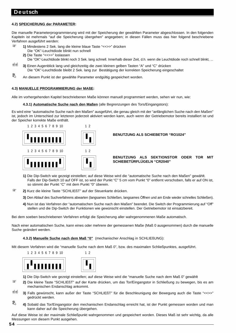
4.2) SPEICHERUNG der PARAMETER:
Die manuelle Parameterprogrammierung wird mit der Speicherung der gewählten Parameter abgeschlossen. In den folgendenKapiteln ist mehrmals “auf die Speicherung übergehen” angegeben; in diesen Fällen muss das hier folgend beschriebeneVerfahren ausgeführt werden:
1) Mindestens 2 Sek. lang die kleine blaue Taste “<<>>” drückenDie “OK”-Leuchtdiode blinkt nun schnell
2) Die Taste “<<>>” loslassenDie “OK”-Leuchtdiode blinkt noch 3 Sek. lang schnell. Innerhalb dieser Zeit, d.h. wenn die Leuchtdiode noch schnell blinkt, ...
3) Einen Augenblick lang und gleichzeitig die zwei kleinen gelben Tasten “A” und “C” drückenDie “OK”-Leuchtdiode bleibt 2 Sek. lang zur Bestätigung der korrekten Speicherung eingeschaltet
An diesem Punkt ist der gewählte Parameter endgültig gespeichert worden.
4.3) MANUELLE PROGRAMMIERUNG der MAßE :
Alle im vorhergehenden Kapitel beschriebenen Maße können manuell programmiert werden, sehen wir nun, wie:
4.3.1) Automatische Suche nach den Maßen (alle Begrenzungen des Tors/Eingangstors):
Es wird eine “automatische Suche nach den Maßen” ausgeführt, die genau gleich mit der “anfänglichen Suche nach den Maßen”ist, jedoch im Unterschied zur letzteren jederzeit aktiviert werden kann, auch wenn der Getriebemotor bereits installiert ist undder Speicher korrekte Maße enthält.
1) Die Dip-Switch wie gezeigt einstellen; auf diese Weise wird die “automatische Suche nach den Maßen” gewählt.Falls der Dip-Switch 10 auf OFF ist, so wird der Punkt “C” 5 cm vom Punkt “0” entfernt verschoben, falls er auf ON ist,so stimmt der Punkt “C” mit dem Punkt “0” überein.
2) Kurz die kleine Taste “SCHLIEßT” auf der Steuerkarte drücken.
3) Den Ablauf des Suchverfahrens abwarten (langsames Schließen, langsames Öffnen und am Ende wieder schnelles Schließen).
4) Nun ist das Verfahren der “automatischen Suche nach den Maßen” beendet. Die Switch der Programmierung auf “Off”stellen und die Dip-Switch der Funktionen wie gewünscht einstellen. Der Getriebemotor ist einsatzbereit.
Bei dem soeben beschriebenen Verfahren erfolgt die Speicherung aller wahrgenommenen Maße automatisch.
Nach einer automatischen Suche, kann eines oder mehrere der gemessenen Maße (Maß 0 ausgenommen) durch die manuelleSuche geändert werden.
4.3.2) Manuelle Suche nach dem Maß “0” (mechanischer Anschlag in SCHLIEßUNG):
Mit diesem Verfahren wird die “manuelle Suche nach dem Maß 0”, bzw. des maximalen Schließpunktes, ausgeführt.
1) Die Dip-Switch wie gezeigt einstellen; auf diese Weise wird die “manuelle Suche nach dem Maß 0” gewählt
2) Die kleine Taste “SCHLIEßT” auf der Karte drücken, um das Tor/Eingangstor in Schließung zu bewegen, bis es ammechanischen Endanschlag ankommt.
3) Falls gewünscht, kann außer der Taste “SCHLIEßT” für die Beschleunigung der Bewegung auch die Taste “<<>>”gedrückt werden.
4) Sobald das Tor/Eingangstor den mechanischen Endanschlag erreicht hat, ist der Punkt gemessen worden und mankann daher auf die Speicherung übergehen.
Auf diese Weise ist der maximale Schließpunkt wahrgenommen und gespeichert worden. Dieses Maß ist sehr wichtig, da alleMessungen von diesem Punkt ausgehen.
Deutsch
54
1 2 3 4 5 6 7 8 9 10 1 2
1 2 3 4 5 6 7 8 9 10 1 2
BENUTZUNG ALS SCHIEBETOR “RO1024”
BENUTZUNG ALS SEKTIONSTOR ODER TOR MITSCHIEBETÜRFLÜGELN “CR2040”
1 2 3 4 5 6 7 8 9 10 1 2
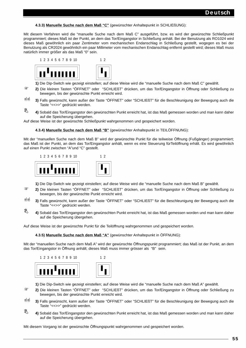
4.3.3) Manuelle Suche nach dem Maß “C” (gewünschter Anhaltepunkt in SCHLIEßUNG):
Mit diesem Verfahren wird die “manuelle Suche nach dem Maß C” ausgeführt, bzw. es wird der gewünschte Schließpunktprogrammiert; dieses Maß ist der Punkt, an dem das Tor/Eingangstor in Schließung anhält. Bei der Benutzung als RO1024 wirddieses Maß gewöhnlich ein paar Zentimeter vom mechanischen Endanschlag in Schließung gestellt, wogegen es bei derBenutzung als CR2024 gewöhnlich ein paar Millimeter vom mechanischen Endanschlag entfernt gestellt wird; dieses Maß mussnatürlich immer größer als das Maß “0” sein.
1) Die Dip-Switch wie gezeigt einstellen; auf diese Weise wird die “manuelle Suche nach dem Maß C” gewählt.
2) Die kleinen Tasten “ÖFFNET” oder “SCHLIEßT” drücken, um das Tor/Eingangstor in Öffnung oder Schließung zubewegen, bis der gewünschte Punkt erreicht wird.
3) Falls gewünscht, kann außer der Taste “ÖFFNET” oder “SCHLIEßT” für die Beschleunigung der Bewegung auch dieTaste “<<>>” gedrückt werden.
4) Sobald das Tor/Eingangstor den gewünschten Punkt erreicht hat, ist das Maß gemessen worden und man kann daherauf die Speicherung übergehen.
Auf diese Weise ist der gewünschte Schließpunkt wahrgenommen und gespeichert worden.
4.3.4) Manuelle Suche nach dem Maß “B” (gewünschter Anhaltepunkt in TEILÖFFNUNG):
Mit der “manuellen Suche nach dem Maß B” wird der gewünschte Punkt für die teilweise Öffnung (Fußgänger) programmiert;das Maß ist der Punkt, an dem das Tor/Eingangstor anhält, wenn es eine Steuerung fürTeilöffnung erhält. Es wird gewöhnlichauf einen Punkt zwischen “A”und “C” gestellt.
1) Die Dip-Switch wie gezeigt einstellen; auf diese Weise wird die “manuelle Suche nach dem Maß B” gewählt.
2) Die kleinen Tasten “ÖFFNET” oder “SCHLIEßT” drücken, um das Tor/Eingangstor in Öffnung oder Schließung zubewegen, bis der gewünschte Punkt erreicht wird.
3) Falls gewünscht, kann außer der Taste “ÖFFNET” oder “SCHLIEßT” für die Beschleunigung der Bewegung auch dieTaste “<<>>” gedrückt werden.
4) Sobald das Tor/Eingangstor den gewünschten Punkt erreicht hat, ist das Maß gemessen worden und man kann daherauf die Speicherung übergehen.
Auf diese Weise ist der gewünschte Punkt für die Teilöffnung wahrgenommen und gespeichert worden.
4.3.5) Manuelle Suche nach dem Maß “A” (gewünschter Anhaltepunkt in ÖFFNUNG):
Mit der “manuellen Suche nach dem Maß A” wird der gewünschte Öffnungspunkt programmiert; das Maß ist der Punkt, an demdas Tor/Eingangstor in Öffnung anhält; dieses Maß muss immer grösser als “B” sein.
1) Die Dip-Switch wie gezeigt einstellen; auf diese Weise wird die “manuelle Suche nach dem Maß A” gewählt.
2) Die kleinen Tasten “ÖFFNET” oder “SCHLIEßT” drücken, um das Tor/Eingangstor in Öffnung oder Schließung zubewegen, bis der gewünschte Punkt erreicht wird.
3) Falls gewünscht, kann außer der Taste “ÖFFNET” oder “SCHLIEßT” für die Beschleunigung der Bewegung auch dieTaste “<<>>” gedrückt werden.
4) Sobald das Tor/Eingangstor den gewünschten Punkt erreicht hat, ist das Maß gemessen worden und man kann daherauf die Speicherung übergehen.
Mit diesem Vorgang ist der gewünschte Öffnungspunkt wahrgenommen und gespeichert worden.
Deutsch
55
1 2 3 4 5 6 7 8 9 10 1 2
1 2 3 4 5 6 7 8 9 10 1 2
1 2 3 4 5 6 7 8 9 10 1 2
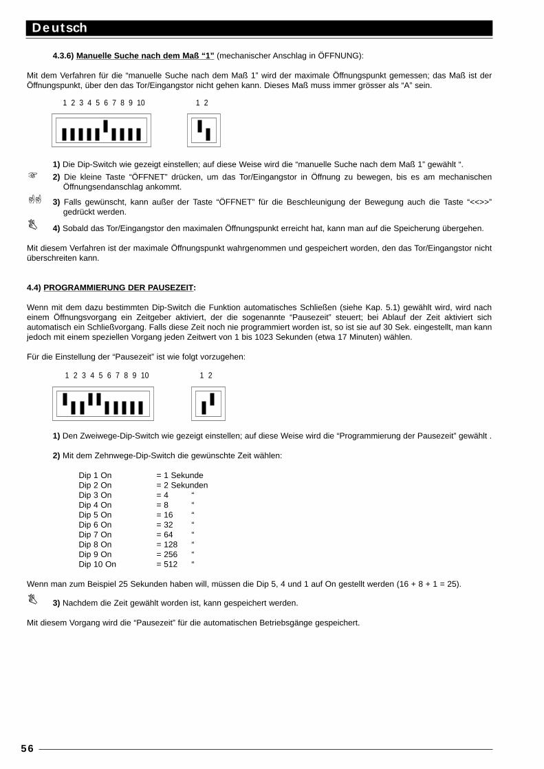
4.3.6) Manuelle Suche nach dem Maß “1” (mechanischer Anschlag in ÖFFNUNG):
Mit dem Verfahren für die “manuelle Suche nach dem Maß 1” wird der maximale Öffnungspunkt gemessen; das Maß ist derÖffnungspunkt, über den das Tor/Eingangstor nicht gehen kann. Dieses Maß muss immer grösser als “A” sein.
1) Die Dip-Switch wie gezeigt einstellen; auf diese Weise wird die “manuelle Suche nach dem Maß 1” gewählt “.
2) Die kleine Taste “ÖFFNET” drücken, um das Tor/Eingangstor in Öffnung zu bewegen, bis es am mechanischenÖffnungsendanschlag ankommt.
3) Falls gewünscht, kann außer der Taste “ÖFFNET” für die Beschleunigung der Bewegung auch die Taste “<<>>”gedrückt werden.
4) Sobald das Tor/Eingangstor den maximalen Öffnungspunkt erreicht hat, kann man auf die Speicherung übergehen.
Mit diesem Verfahren ist der maximale Öffnungspunkt wahrgenommen und gespeichert worden, den das Tor/Eingangstor nichtüberschreiten kann.
4.4) PROGRAMMIERUNG DER PAUSEZEIT:
Wenn mit dem dazu bestimmten Dip-Switch die Funktion automatisches Schließen (siehe Kap. 5.1) gewählt wird, wird nacheinem Öffnungsvorgang ein Zeitgeber aktiviert, der die sogenannte “Pausezeit” steuert; bei Ablauf der Zeit aktiviert sichautomatisch ein Schließvorgang. Falls diese Zeit noch nie programmiert worden ist, so ist sie auf 30 Sek. eingestellt, man kannjedoch mit einem speziellen Vorgang jeden Zeitwert von 1 bis 1023 Sekunden (etwa 17 Minuten) wählen.
Für die Einstellung der “Pausezeit” ist wie folgt vorzugehen:
1) Den Zweiwege-Dip-Switch wie gezeigt einstellen; auf diese Weise wird die “Programmierung der Pausezeit” gewählt .
2) Mit dem Zehnwege-Dip-Switch die gewünschte Zeit wählen:
Dip 1 On = 1 SekundeDip 2 On = 2 SekundenDip 3 On = 4 “Dip 4 On = 8 “Dip 5 On = 16 “Dip 6 On = 32 “Dip 7 On = 64 “Dip 8 On = 128 “Dip 9 On = 256 “Dip 10 On = 512 “
Wenn man zum Beispiel 25 Sekunden haben will, müssen die Dip 5, 4 und 1 auf On gestellt werden (16 + 8 + 1 = 25).
3) Nachdem die Zeit gewählt worden ist, kann gespeichert werden.
Mit diesem Vorgang wird die “Pausezeit” für die automatischen Betriebsgänge gespeichert.
Deutsch
56
1 2 3 4 5 6 7 8 9 10 1 2
1 2 3 4 5 6 7 8 9 10 1 2
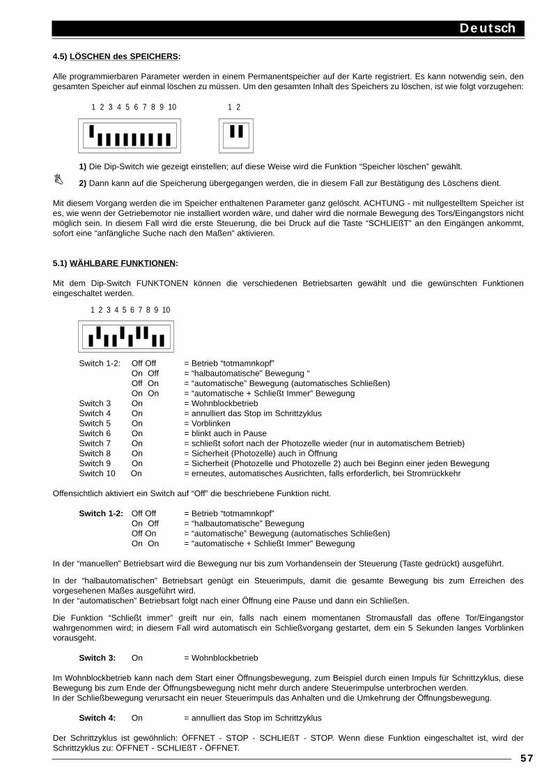
4.5) LÖSCHEN des SPEICHERS :
Alle programmierbaren Parameter werden in einem Permanentspeicher auf der Karte registriert. Es kann notwendig sein, dengesamten Speicher auf einmal löschen zu müssen. Um den gesamten Inhalt des Speichers zu löschen, ist wie folgt vorzugehen:
1) Die Dip-Switch wie gezeigt einstellen; auf diese Weise wird die Funktion “Speicher löschen” gewählt.
2) Dann kann auf die Speicherung übergegangen werden, die in diesem Fall zur Bestätigung des Löschens dient.
Mit diesem Vorgang werden die im Speicher enthaltenen Parameter ganz gelöscht. ACHTUNG - mit nullgestelltem Speicher istes, wie wenn der Getriebemotor nie installiert worden wäre, und daher wird die normale Bewegung des Tors/Eingangstors nichtmöglich sein. In diesem Fall wird die erste Steuerung, die bei Druck auf die Taste “SCHLIEßT” an den Eingängen ankommt,sofort eine “anfängliche Suche nach den Maßen” aktivieren.
5.1) WÄHLBARE FUNKTIONEN :
Mit dem Dip-Switch FUNKTONEN können die verschiedenen Betriebsarten gewählt und die gewünschten Funktioneneingeschaltet werden.
Switch 1-2: Off Off = Betrieb “totmamnkopf”On Off = “halbautomatische” Bewegung “Off On = “automatische” Bewegung (automatisches Schließen)On On = “automatische + Schließt Immer” Bewegung
Switch 3 On = WohnblockbetriebSwitch 4 On = annulliert das Stop im SchrittzyklusSwitch 5 On = VorblinkenSwitch 6 On = blinkt auch in PauseSwitch 7 On = schließt sofort nach der Photozelle wieder (nur in automatischem Betrieb)Switch 8 On = Sicherheit (Photozelle) auch in ÖffnungSwitch 9 On = Sicherheit (Photozelle und Photozelle 2) auch bei Beginn einer jeden Bewegung Switch 10 On = erneutes, automatisches Ausrichten, falls erforderlich, bei Stromrückkehr
Offensichtlich aktiviert ein Switch auf “Off” die beschriebene Funktion nicht.
Switch 1-2: Off Off = Betrieb “totmamnkopf”On Off = “halbautomatische” BewegungOff On = “automatische” Bewegung (automatisches Schließen)On On = “automatische + Schließt Immer” Bewegung
In der “manuellen” Betriebsart wird die Bewegung nur bis zum Vorhandensein der Steuerung (Taste gedrückt) ausgeführt.
In der “halbautomatischen” Betriebsart genügt ein Steuerimpuls, damit die gesamte Bewegung bis zum Erreichen desvorgesehenen Maßes ausgeführt wird.In der “automatischen” Betriebsart folgt nach einer Öffnung eine Pause und dann ein Schließen.
Die Funktion “Schließt immer” greift nur ein, falls nach einem momentanen Stromausfall das offene Tor/Eingangstorwahrgenommen wird; in diesem Fall wird automatisch ein Schließvorgang gestartet, dem ein 5 Sekunden langes Vorblinkenvorausgeht.
Switch 3: On = Wohnblockbetrieb
Im Wohnblockbetrieb kann nach dem Start einer Öffnungsbewegung, zum Beispiel durch einen Impuls für Schrittzyklus, dieseBewegung bis zum Ende der Öffnungsbewegung nicht mehr durch andere Steuerimpulse unterbrochen werden.In der Schließbewegung verursacht ein neuer Steuerimpuls das Anhalten und die Umkehrung der Öffnungsbewegung.
Switch 4: On = annulliert das Stop im Schrittzyklus
Der Schrittzyklus ist gewöhnlich: ÖFFNET - STOP - SCHLIEßT - STOP. Wenn diese Funktion eingeschaltet ist, wird derSchrittzyklus zu: ÖFFNET - SCHLIEßT - ÖFFNET.
Deutsch
57
1 2 3 4 5 6 7 8 9 10 1 2
1 2 3 4 5 6 7 8 9 10
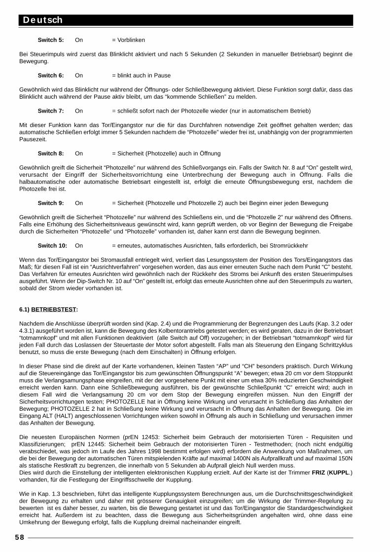
Switch 5: On = Vorblinken
Bei Steuerimpuls wird zuerst das Blinklicht aktiviert und nach 5 Sekunden (2 Sekunden in manueller Betriebsart) beginnt dieBewegung.
Switch 6: On = blinkt auch in Pause
Gewöhnlich wird das Blinklicht nur während der Öffnungs- oder Schließbewegung aktiviert. Diese Funktion sorgt dafür, dass dasBlinklicht auch während der Pause aktiv bleibt, um das “kommende Schließen” zu melden.
Switch 7: On = schließt sofort nach der Photozelle wieder (nur in automatischem Betrieb)
Mit dieser Funktion kann das Tor/Eingangstor nur die für das Durchfahren notwendige Zeit geöffnet gehalten werden; dasautomatische Schließen erfolgt immer 5 Sekunden nachdem die “Photozelle” wieder frei ist, unabhängig von der programmiertenPausezeit.
Switch 8: On = Sicherheit (Photozelle) auch in Öffnung
Gewöhnlich greift die Sicherheit “Photozelle” nur während des Schließvorgangs ein. Falls der Switch Nr. 8 auf “On” gestellt wird,verursacht der Eingriff der Sicherheitsvorrichtung eine Unterbrechung der Bewegung auch in Öffnung. Falls diehalbautomatische oder automatische Betriebsart eingestellt ist, erfolgt die erneute Öffnungsbewegung erst, nachdem diePhotozelle frei ist.
Switch 9: On = Sicherheit (Photozelle und Photozelle 2) auch bei Beginn einer jeden Bewegung
Gewöhnlich greift die Sicherheit “Photozelle” nur während des Schließens ein, und die “Photozelle 2” nur während des Öffnens.Falls eine Erhöhung des Sicherheitsniveaus gewünscht wird, kann geprüft werden, ob vor Beginn der Bewegung die Freigabedurch die Sicherheiten “Photozelle” und “Photozelle” vorhanden ist, daher kann erst dann die Bewegung beginnen.
Switch 10: On = erneutes, automatisches Ausrichten, falls erforderlich, bei Stromrückkehr
Wenn das Tor/Eingangstor bei Stromausfall entriegelt wird, verliert das Lesungssystem der Position des Tors/Eingangstors dasMaß; für diesen Fall ist ein “Ausrichtverfahren” vorgesehen worden, das aus einer erneuten Suche nach dem Punkt “C” besteht.Das Verfahren für erneutes Ausrichten wird gewöhnlich nach der Rückkehr des Stroms bei Ankunft des ersten Steuerimpulsesausgeführt. Wenn der Dip-Switch Nr. 10 auf “On” gestellt ist, erfolgt das erneute Ausrichten ohne auf den Steuerimpuls zu warten,sobald der Strom wieder vorhanden ist.
6.1) BETRIEBSTEST:
Nachdem die Anschlüsse überprüft worden sind (Kap. 2.4) und die Programmierung der Begrenzungen des Laufs (Kap. 3.2 oder4.3.1) ausgeführt worden ist, kann die Bewegung des Kolbentorantriebs getestet werden; es wird geraten, dazu in der Betriebsart“totmamnkopf” und mit allen Funktionen deaktiviert (alle Switch auf Off) vorzugehen; in der Betriebsart “totmamnkopf” wird fürjeden Fall durch das Loslassen der Steuertaste der Motor sofort abgestellt. Falls man als Steuerung den Eingang Schrittzyklusbenutzt, so muss die erste Bewegung (nach dem Einschalten) in Öffnung erfolgen.
In dieser Phase sind die direkt auf der Karte vorhandenen, kleinen Tasten “AP” und “CH” besonders praktisch. Durch Wirkungauf die Steuereingänge das Tor/Eingangstor bis zum gewünschten Öffnungspunkt “A” bewegen; etwa 20 cm vor dem Stoppunktmuss die Verlangsamungsphase eingreifen, mit der der vorgesehene Punkt mit einer um etwa 30% reduzierten Geschwindigkeiterreicht werden kann. Dann eine Schließbewegung ausführen, bis der gewünschte Schließpunkt “C” erreicht wird; auch indiesem Fall wird die Verlangsamung 20 cm vor dem Stop der Bewegung eingreifen müssen. Nun den Eingriff derSicherheitsvorrichtungen testen; PHOTOZELLE hat in Öffnung keine Wirkung und verursacht in Schließung das Anhalten derBewegung; PHOTOZELLE 2 hat in Schließung keine Wirkung und verursacht in Öffnung das Anhalten der Bewegung. Die imEingang ALT (HALT) angeschlossenen Vorrichtungen wirken sowohl in Öffnung als auch in Schließung und verursachen immerdas Anhalten der Bewegung.
Die neuesten Europäischen Normen (prEN 12453: Sicherheit beim Gebrauch der motorisierten Türen - Requisiten undKlassifizierungen; prEN 12445: Sicherheit beim Gebrauch der motorisierten Türen - Testmethoden; (noch nicht endgültigverabschiedet, was jedoch im Laufe des Jahres 1998 bestimmt erfolgen wird) erfordern die Anwendung von Maßnahmen, umdie bei der Bewegung der automatischen Türen mitspielenden Kräfte auf maximal 1400N als Aufprallkraft und auf maximal 150Nals statische Restkraft zu begrenzen, die innerhalb von 5 Sekunden ab Aufprall gleich Null werden muss.Dies wird durch die Einstellung der intelligenten elektronischen Kupplung erzielt. Auf der Karte ist der Trimmer FRIZ (KUPPL .)vorhanden, für die Festlegung der Eingriffsschwelle der Kupplung.
Wie in Kap. 1.3 beschrieben, führt das intelligente Kupplungssystem Berechnungen aus, um die Durchschnittsgeschwindigkeitder Bewegung zu erhalten und daher mit grösserer Genauigkeit einzugreifen; um die Wirkung der Trimmer-Regelung zubewerten ist es daher besser, zu warten, bis die Bewegung gestartet ist und das Tor/Eingangstor die Standardgeschwindigkeiterreicht hat. Außerdem ist zu beachten, dass die Bewegung aus Sicherheitsgründen angehalten wird, ohne dass eineUmkehrung der Bewegung erfolgt, falls die Kupplung dreimal nacheinander eingreift.
Deutsch
58
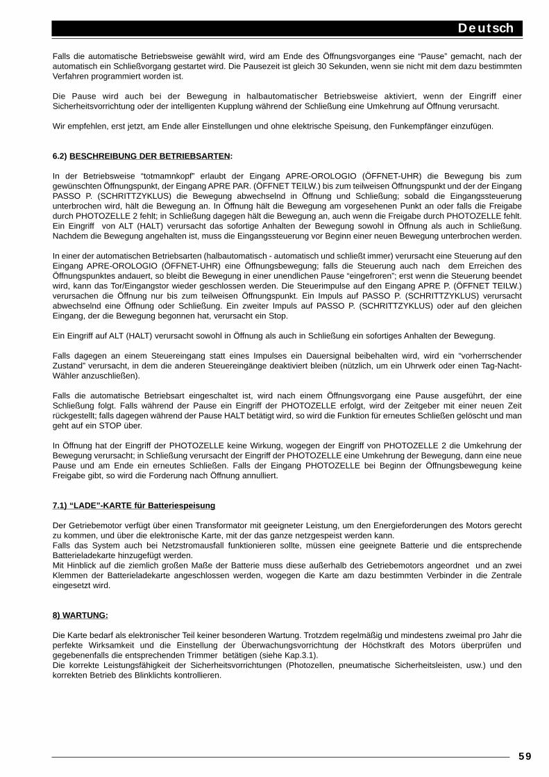
Falls die automatische Betriebsweise gewählt wird, wird am Ende des Öffnungsvorganges eine “Pause” gemacht, nach derautomatisch ein Schließvorgang gestartet wird. Die Pausezeit ist gleich 30 Sekunden, wenn sie nicht mit dem dazu bestimmtenVerfahren programmiert worden ist.
Die Pause wird auch bei der Bewegung in halbautomatischer Betriebsweise aktiviert, wenn der Eingriff einerSicherheitsvorrichtung oder der intelligenten Kupplung während der Schließung eine Umkehrung auf Öffnung verursacht.
Wir empfehlen, erst jetzt, am Ende aller Einstellungen und ohne elektrische Speisung, den Funkempfänger einzufügen.
6.2) BESCHREIBUNG DER BETRIEBSARTEN :
In der Betriebsweise “totmamnkopf” erlaubt der Eingang APRE-OROLOGIO (ÖFFNET-UHR) die Bewegung bis zumgewünschten Öffnungspunkt, der Eingang APRE PAR. (ÖFFNET TEILW.) bis zum teilweisen Öffnungspunkt und der der EingangPASSO P. (SCHRITTZYKLUS) die Bewegung abwechselnd in Öffnung und Schließung; sobald die Eingangssteuerungunterbrochen wird, hält die Bewegung an. In Öffnung hält die Bewegung am vorgesehenen Punkt an oder falls die Freigabedurch PHOTOZELLE 2 fehlt; in Schließung dagegen hält die Bewegung an, auch wenn die Freigabe durch PHOTOZELLE fehlt.Ein Eingriff von ALT (HALT) verursacht das sofortige Anhalten der Bewegung sowohl in Öffnung als auch in Schließung.Nachdem die Bewegung angehalten ist, muss die Eingangssteuerung vor Beginn einer neuen Bewegung unterbrochen werden.
In einer der automatischen Betriebsarten (halbautomatisch - automatisch und schließt immer) verursacht eine Steuerung auf denEingang APRE-OROLOGIO (ÖFFNET-UHR) eine Öffnungsbewegung; falls die Steuerung auch nach dem Erreichen desÖffnungspunktes andauert, so bleibt die Bewegung in einer unendlichen Pause “eingefroren”; erst wenn die Steuerung beendetwird, kann das Tor/Eingangstor wieder geschlossen werden. Die Steuerimpulse auf den Eingang APRE P. (ÖFFNET TEILW.)verursachen die Öffnung nur bis zum teilweisen Öffnungspunkt. Ein Impuls auf PASSO P. (SCHRITTZYKLUS) verursachtabwechselnd eine Öffnung oder Schließung. Ein zweiter Impuls auf PASSO P. (SCHRITTZYKLUS) oder auf den gleichenEingang, der die Bewegung begonnen hat, verursacht ein Stop.
Ein Eingriff auf ALT (HALT) verursacht sowohl in Öffnung als auch in Schließung ein sofortiges Anhalten der Bewegung.
Falls dagegen an einem Steuereingang statt eines Impulses ein Dauersignal beibehalten wird, wird ein “vorherrschenderZustand” verursacht, in dem die anderen Steuereingänge deaktiviert bleiben (nützlich, um ein Uhrwerk oder einen Tag-Nacht-Wähler anzuschließen).
Falls die automatische Betriebsart eingeschaltet ist, wird nach einem Öffnungsvorgang eine Pause ausgeführt, der eineSchließung folgt. Falls während der Pause ein Eingriff der PHOTOZELLE erfolgt, wird der Zeitgeber mit einer neuen Zeitrückgestellt; falls dagegen während der Pause HALT betätigt wird, so wird die Funktion für erneutes Schließen gelöscht und mangeht auf ein STOP über.
In Öffnung hat der Eingriff der PHOTOZELLE keine Wirkung, wogegen der Eingriff von PHOTOZELLE 2 die Umkehrung derBewegung verursacht; in Schließung verursacht der Eingriff der PHOTOZELLE eine Umkehrung der Bewegung, dann eine neuePause und am Ende ein erneutes Schließen. Falls der Eingang PHOTOZELLE bei Beginn der Öffnungsbewegung keineFreigabe gibt, so wird die Forderung nach Öffnung annulliert.
7.1) “LADE”-KARTE für Batteriespeisung
Der Getriebemotor verfügt über einen Transformator mit geeigneter Leistung, um den Energieforderungen des Motors gerechtzu kommen, und über die elektronische Karte, mit der das ganze netzgespeist werden kann.Falls das System auch bei Netzstromausfall funktionieren sollte, müssen eine geeignete Batterie und die entsprechendeBatterieladekarte hinzugefügt werden.Mit Hinblick auf die ziemlich großen Maße der Batterie muss diese außerhalb des Getriebemotors angeordnet und an zweiKlemmen der Batterieladekarte angeschlossen werden, wogegen die Karte am dazu bestimmten Verbinder in die Zentraleeingesetzt wird.
8) WARTUNG:
Die Karte bedarf als elektronischer Teil keiner besonderen Wartung. Trotzdem regelmäßig und mindestens zweimal pro Jahr dieperfekte Wirksamkeit und die Einstellung der Überwachungsvorrichtung der Höchstkraft des Motors überprüfen undgegebenenfalls die entsprechenden Trimmer betätigen (siehe Kap.3.1).Die korrekte Leistungsfähigkeit der Sicherheitsvorrichtungen (Photozellen, pneumatische Sicherheitsleisten, usw.) und denkorrekten Betrieb des Blinklichts kontrollieren.
Deutsch
59
TECHNISCHE EIGENSCHAFTEN DER ZENTRALE:
Netzspeisung : 230 Vac ±10%, 50 - 60 HzBatteriespeisung : 21 ÷ 28 Vcc (Kapazität > 6Ah)Höchststrom 24 V G.S. der Zubehörteile : 200 mAHöchstleistung des Blinklichtes : 25 W (24 Vcc)Höchstleistung der Kontrollampe für Offenes Tor/Eingangstor : 2 W (24 Vcc)Pausezeit : von 1 bis 1023 SekundenAuflösung des Encoders : 4,73 Grad (76 Impulse/Umdrehung)Betriebstemperatur : -20 ÷ 70 °C
Deutsch
60
Español
61
El presente manual está destinado sólo al personal técnico cualificado encargado de la instalación.¡Ninguna información incluida en el presente manual puede ser de interés para el usuario final!
ÍNDICE:
Guía rápida : 62Introducción : 63
Descripción del producto : 63Instrucciones para la instalación : 64
Esquema de las conexiones : 65Descripción de las conexiones : 65Instrucciones para las conexiones : 66
Límites de la carrera : 67Búsqueda inicial de las cotas : 68
Programación : 68Memorización de los parámetros : 69Programación manual de las cotas : 69Programación del tiempo de pausa : 71Anulación de la memoria : 71
Funciones que se pueden seleccionar : 72Prueba del funcionamiento : 73Descripción de las modalidades de funcionamiento : 73Tarjeta “CARGA” para alimentación por batería : 74Mantenimiento : 74Características técnicas de la central : 74
AVISO IMPORTANTE:
Es nuestro deber recordarle que está realizando operaciones sobre instalaciones de máquinas clasificadas en la categoría de:“Puertas y verjas automáticas” y, por consiguiente, consideradas muy “peligrosas”. Su deber es hacer que las mismas sean“seguras”, dentro de los límites de lo posible.La instalación y las operaciones de mantenimiento tienen que ser efectuados sólo por personal cualificado y experto, siguiendolas indicaciones dictadas por la regla del arte y de conformidad con cuanto previsto por las siguientes leyes, normas o directivas:
89/392 CEE (Directiva Máquinas) 89/336 CEE (Directiva sobre la Compatibilidad Electromagnética) 73/23 CEE (Directiva Baja Tensión) PrEN 12453 (Seguridad en el uso de puertas motorizadas – requisitos y clasificaciones)PrEN 12445 (Seguridad en el uso de puertas motorizadas – métodos de prueba)
En el planeamiento y realización de sus productos, Nice respeta todas estas normativas, por lo que concierne a los aparatos;pero es fundamental que también el instalador respete escrupulosamente las mismas normas por lo que concierne a lasinstalaciones.
El personal no cualificado, o que desconozca las normativas aplicables a la categoría de las “Puertas y verjas automáticas”:
nunca tiene que efectuar operaciones de instalación
Quien efectúe instalaciones sin respetar todas las normativas aplicables:
¡siempre es responsable de los posibles daños que pudiera causar la instalación!
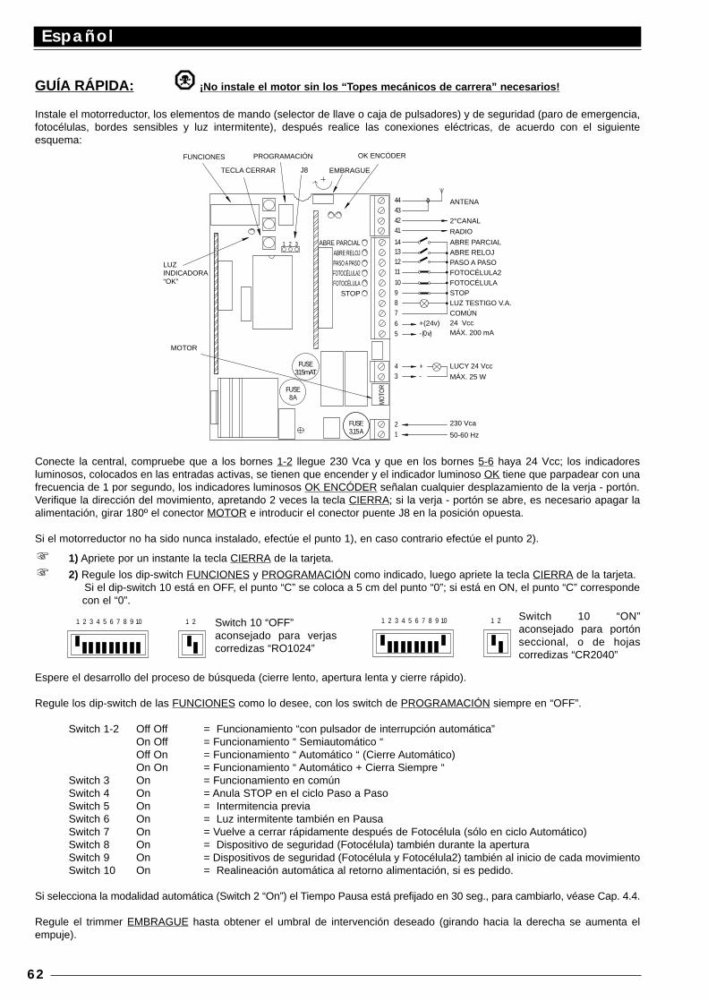
GUÍA RÁPIDA: ¡No instale el motor sin los “T opes mecánicos de carrera” necesarios!
Instale el motorreductor, los elementos de mando (selector de llave o caja de pulsadores) y de seguridad (paro de emergencia,fotocélulas, bordes sensibles y luz intermitente), después realice las conexiones eléctricas, de acuerdo con el siguienteesquema:
Conecte la central, compruebe que a los bornes 1-2 llegue 230 Vca y que en los bornes 5-6 haya 24 Vcc; los indicadoresluminosos, colocados en las entradas activas, se tienen que encender y el indicador luminoso OK tiene que parpadear con unafrecuencia de 1 por segundo, los indicadores luminosos OK ENCÓDER señalan cualquier desplazamiento de la verja - portón.Verifique la dirección del movimiento, apretando 2 veces la tecla CIERRA; si la verja - portón se abre, es necesario apagar laalimentación, girar 180º el conector MOTOR e introducir el conector puente J8 en la posición opuesta.
Si el motorreductor no ha sido nunca instalado, efectúe el punto 1), en caso contrario efectúe el punto 2).
1) Apriete por un instante la tecla CIERRA de la tarjeta.
2) Regule los dip-switch FUNCIONES y PROGRAMACIÓN como indicado, luego apriete la tecla CIERRA de la tarjeta.Si el dip-switch 10 está en OFF, el punto “C” se coloca a 5 cm del punto “0”; si está en ON, el punto “C” correspondecon el “0”.
Espere el desarrollo del proceso de búsqueda (cierre lento, apertura lenta y cierre rápido).
Regule los dip-switch de las FUNCIONES como lo desee, con los switch de PROGRAMACIÓN siempre en “OFF”.
Switch 1-2 Off Off = Funcionamiento “con pulsador de interrupción automática”On Off = Funcionamiento “ Semiautomático “Off On = Funcionamiento “ Automático “ (Cierre Automático)On On = Funcionamiento “ Automático + Cierra Siempre “
Switch 3 On = Funcionamiento en comúnSwitch 4 On = Anula STOP en el ciclo Paso a PasoSwitch 5 On = Intermitencia previaSwitch 6 On = Luz intermitente también en PausaSwitch 7 On = Vuelve a cerrar rápidamente después de Fotocélula (sólo en ciclo Automático)Switch 8 On = Dispositivo de seguridad (Fotocélula) también durante la aperturaSwitch 9 On = Dispositivos de seguridad (Fotocélula y Fotocélula2) también al inicio de cada movimientoSwitch 10 On = Realineación automática al retorno alimentación, si es pedido.
Si selecciona la modalidad automática (Switch 2 “On”) el Tiempo Pausa está prefijado en 30 seg., para cambiarlo, véase Cap. 4.4.
Regule el trimmer EMBRAGUE hasta obtener el umbral de intervención deseado (girando hacia la derecha se aumenta elempuje).
Español
62
- (0 v)
MOTOR
8 A
315mAT
FUSE
FUSE
1
MO
TOR
FUSE3,15 A
2
34 +
-
LUZ INDICADORA “OK”
FUNCIONES
31 2
J8
PROGRAMACIÓN
TECLA CERRAR
98
65
+(24v)
7
11
10
1312
14
41
4342
44
EMBRAGUE
OK ENCÓDER
ANTENA
2°CANAL
RADIO
ABRE PARCIAL ABRE RELOJ PASO A PASO FOTOCÉLULA2 FOTOCÉLULA STOP LUZ TESTIGO V.A. COMÚN 24 Vcc MÁX. 200 mA
LUCY 24 Vcc
MÁX. 25 W
230 Vca
50-60 Hz
ABRE PARCIAL ABRE RELOJ PASO A PASO FOTOCÉLULA2 FOTOCÉLULA
STOP
1 2 3 4 5 6 7 8 9 10 1 2 1 2 3 4 5 6 7 8 9 10 1 2Switch 10 “OFF”aconsejado para verjascorredizas “RO1024”
Switch 10 “ON”aconsejado para portónseccional, o de hojascorredizas “CR2040”
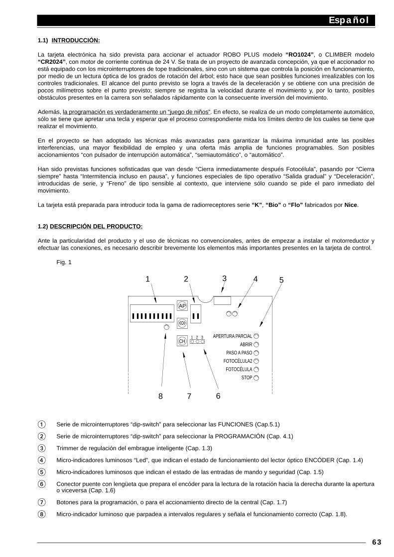
1.1) INTRODUCCIÓN:
La tarjeta electrónica ha sido prevista para accionar el actuador ROBO PLUS modelo “RO1024” , o CLIMBER modelo“CR2024” , con motor de corriente continua de 24 V. Se trata de un proyecto de avanzada concepción, ya que el accionador noestá equipado con los microinterruptores de tope tradicionales, sino con un sistema que controla la posición en funcionamiento,por medio de un lectura óptica de los grados de rotación del árbol; esto hace que sean posibles funciones irrealizables con loscontroles tradicionales. El alcance del punto previsto se logra a través de la deceleración y se obtiene con una precisión depocos milímetros sobre el punto previsto; siempre se registra la velocidad durante el movimiento y, por lo tanto, posiblesobstáculos presentes en la carrera son señalados rápidamente con la consecuente inversión del movimiento.
Además, la programación es verdaderamente un “juego de niños”. En efecto, se realiza de un modo completamente automático,sólo se tiene que apretar una tecla y esperar que el proceso correspondiente mida los límites dentro de los cuales se tiene querealizar el movimiento.
En el proyecto se han adoptado las técnicas más avanzadas para garantizar la máxima inmunidad ante las posiblesinterferencias, una mayor flexibilidad de empleo y una oferta más amplia de funciones programables. Son posiblesaccionamientos “con pulsador de interrupción automática”, “semiautomático”, o “automático”.
Han sido previstas funciones sofisticadas que van desde “Cierra inmediatamente después Fotocélula”, pasando por “Cierrasiempre” hasta “Intermitencia incluso en pausa”, y funciones especiales de tipo operativo “Salida gradual” y “Deceleración”,introducidas de serie, y “Freno” de tipo sensible al contexto, que interviene sólo cuando se pide el paro inmediato delmovimiento.
La tarjeta está preparada para introducir toda la gama de radiorreceptores serie “K” , “Bio” o “Flo” fabricados por Nice .
1.2) DESCRIPCIÓN DEL PRODUCTO:
Ante la particularidad del producto y el uso de técnicas no convencionales, antes de empezar a instalar el motorreductor yefectuar las conexiones, es necesario describir brevemente los elementos más importantes presentes en la tarjeta de control.
Fig. 1
1 Serie de microinterruptores “dip-switch” para seleccionar las FUNCIONES (Cap.5.1)
2 Serie de microinterruptores “dip-switch” para seleccionar la PROGRAMACIÓN (Cap. 4.1)
3 Trimmer de regulación del embrague inteligente (Cap. 1.3)
4 Micro-indicadores luminosos “Led”, que indican el estado de funcionamiento del lector óptico ENCÓDER (Cap. 1.4)
5 Micro-indicadores luminosos que indican el estado de las entradas de mando y seguridad (Cap. 1.5)
6 Conector puente con lengüeta que prepara el encóder para la lectura de la rotación hacia la derecha durante la aperturao viceversa (Cap. 1.6)
7 Botones para la programación, o para el accionamiento directo de la central (Cap. 1.7)
8 Micro-indicador luminoso que parpadea a intervalos regulares y señala el funcionamiento correcto (Cap. 1.8).
Español
63
31 2CH
68 7
3
AP
<<>>
21 54
APERTURA PARCIAL
ABRIR
PASO A PASO
FOTOCÉLULA2
FOTOCÉLULA
STOP
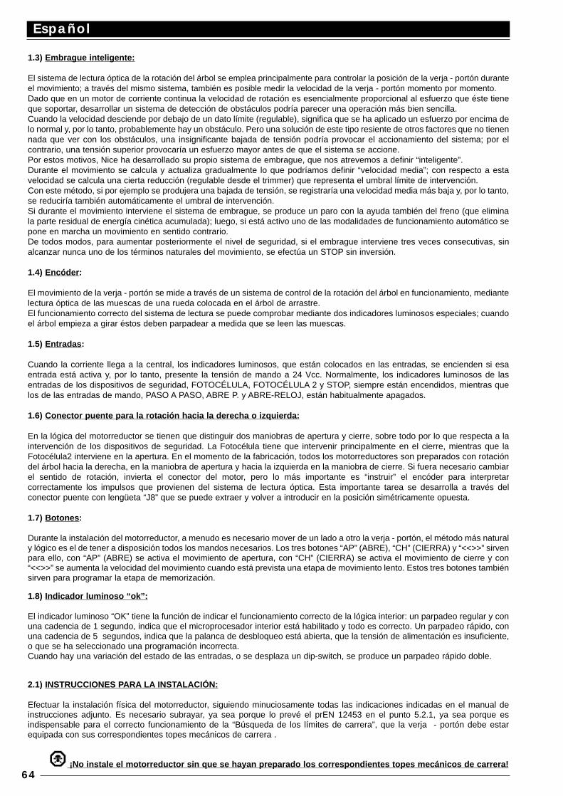
1.3) Embrague inteligente:
El sistema de lectura óptica de la rotación del árbol se emplea principalmente para controlar la posición de la verja - portón duranteel movimiento; a través del mismo sistema, también es posible medir la velocidad de la verja - portón momento por momento.Dado que en un motor de corriente continua la velocidad de rotación es esencialmente proporcional al esfuerzo que éste tieneque soportar, desarrollar un sistema de detección de obstáculos podría parecer una operación más bien sencilla.Cuando la velocidad desciende por debajo de un dato límite (regulable), significa que se ha aplicado un esfuerzo por encima delo normal y, por lo tanto, probablemente hay un obstáculo. Pero una solución de este tipo resiente de otros factores que no tienennada que ver con los obstáculos, una insignificante bajada de tensión podría provocar el accionamiento del sistema; por elcontrario, una tensión superior provocaría un esfuerzo mayor antes de que el sistema se accione.Por estos motivos, Nice ha desarrollado su propio sistema de embrague, que nos atrevemos a definir “inteligente”.Durante el movimiento se calcula y actualiza gradualmente lo que podríamos definir “velocidad media”; con respecto a estavelocidad se calcula una cierta reducción (regulable desde el trimmer) que representa el umbral límite de intervención. Con este método, si por ejemplo se produjera una bajada de tensión, se registraría una velocidad media más baja y, por lo tanto,se reduciría también automáticamente el umbral de intervención. Si durante el movimiento interviene el sistema de embrague, se produce un paro con la ayuda también del freno (que eliminala parte residual de energía cinética acumulada); luego, si está activo uno de las modalidades de funcionamiento automático sepone en marcha un movimiento en sentido contrario.De todos modos, para aumentar posteriormente el nivel de seguridad, si el embrague interviene tres veces consecutivas, sinalcanzar nunca uno de los términos naturales del movimiento, se efectúa un STOP sin inversión.
1.4) Encóder :
El movimiento de la verja - portón se mide a través de un sistema de control de la rotación del árbol en funcionamiento, mediantelectura óptica de las muescas de una rueda colocada en el árbol de arrastre.El funcionamiento correcto del sistema de lectura se puede comprobar mediante dos indicadores luminosos especiales; cuandoel árbol empieza a girar éstos deben parpadear a medida que se leen las muescas.
1.5) Entradas :
Cuando la corriente llega a la central, los indicadores luminosos, que están colocados en las entradas, se encienden si esaentrada está activa y, por lo tanto, presente la tensión de mando a 24 Vcc. Normalmente, los indicadores luminosos de lasentradas de los dispositivos de seguridad, FOTOCÉLULA, FOTOCÉLULA 2 y STOP, siempre están encendidos, mientras quelos de las entradas de mando, PASO A PASO, ABRE P. y ABRE-RELOJ, están habitualmente apagados.
1.6) Conector puente para la rotación hacia la derecha o izquierda:
En la lógica del motorreductor se tienen que distinguir dos maniobras de apertura y cierre, sobre todo por lo que respecta a laintervención de los dispositivos de seguridad. La Fotocélula tiene que intervenir principalmente en el cierre, mientras que laFotocélula2 interviene en la apertura. En el momento de la fabricación, todos los motorreductores son preparados con rotacióndel árbol hacia la derecha, en la maniobra de apertura y hacia la izquierda en la maniobra de cierre. Si fuera necesario cambiarel sentido de rotación, invierta el conector del motor, pero lo más importante es “instruir” el encóder para interpretarcorrectamente los impulsos que provienen del sistema de lectura óptica. Esta importante tarea se desarrolla a través delconector puente con lengüeta “J8” que se puede extraer y volver a introducir en la posición simétricamente opuesta.
1.7) Botones :
Durante la instalación del motorreductor, a menudo es necesario mover de un lado a otro la verja - portón, el método más naturaly lógico es el de tener a disposición todos los mandos necesarios. Los tres botones “AP” (ABRE), “CH” (CIERRA) y “<<>>” sirvenpara ello, con “AP” (ABRE) se activa el movimiento de apertura, con “CH” (CIERRA) se activa el movimiento de cierre y con“<<>>” se aumenta la velocidad del movimiento cuando está prevista una etapa de movimiento lento. Estos tres botones tambiénsirven para programar la etapa de memorización.
1.8) Indicador luminoso “ok”:
El indicador luminoso “OK” tiene la función de indicar el funcionamiento correcto de la lógica interior: un parpadeo regular y conuna cadencia de 1 segundo, indica que el microprocesador interior está habilitado y todo es correcto. Un parpadeo rápido, conuna cadencia de 5 segundos, indica que la palanca de desbloqueo está abierta, que la tensión de alimentación es insuficiente,o que se ha seleccionado una programación incorrecta.Cuando hay una variación del estado de las entradas, o se desplaza un dip-switch, se produce un parpadeo rápido doble.
2.1) INSTRUCCIONES PARA LA INSTALACIÓN:
Efectuar la instalación física del motorreductor, siguiendo minuciosamente todas las indicaciones indicadas en el manual deinstrucciones adjunto. Es necesario subrayar, ya sea porque lo prevé el prEN 12453 en el punto 5.2.1, ya sea porque esindispensable para el correcto funcionamiento de la “Búsqueda de los límites de carrera”, que la verja - portón debe estarequipada con sus correspondientes topes mecánicos de carrera .
¡No instale el motorreductor sin que se hayan preparado los correspondientes topes mecánicos de carrera!
Español
64
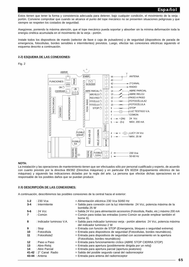
Estos tienen que tener la forma y consistencia adecuada para detener, bajo cualquier condición, el movimiento de la verja -portón. Conviene comprobar que cuando se alcance el punto del tope mecánico no se presenten situaciones peligrosas y quesiempre se respeten los costados de seguridad.
Asegúrese, poniendo la máxima atención, que el tope mecánico pueda soportar y absorber sin la mínima deformación toda laenergía cinética acumulada en el movimiento de la verja - portón.
Instale todos los dispositivos de mando (selector de llave o caja de pulsadores) y de seguridad (dispositivos de parada deemergencia, fotocélulas, bordes sensibles e intermitentes) previstos. Luego, efectúe las conexiones eléctricas siguiendo elesquema descrito a continuación.
2.2) ESQUEMA DE LAS CONEXIONES:
Fig. 2
NOTA:La instalación y las operaciones de mantenimiento tienen que ser efectuados sólo por personal cualificado y experto, de acuerdocon cuanto previsto por la directiva 89/392 (Directiva máquinas) y en particular EN 60204 (Equipamiento eléctrico de lasmáquinas) y siguiendo las indicaciones dictadas por la regla del arte. La persona que efectúe dichas operaciones es elresponsable de los posibles daños que se puedan producir.
2.3) DESCRIPCIÓN DE LAS CONEXIONES:
A continuación, describiremos las posibles conexiones de la central hacia el exterior:
1-2 : 230 Vca = Alimentación eléctrica 230 Vca 50/60 Hz3-4 : Intermitente = Salida para conexión con la luz intermitente 24 Vcc, potencia máxima de la
bombilla 25 W5-6 : 24 Vcc = Salida 24 Vcc para alimentación accesorios (Fotocélula, Radio, etc.) máximo 200 mA7 : Común = Común para todas las entradas (como Común se puede emplear también el
borne 6).8 : Indicador luminoso V.A. = Salida para indicador luminoso verja - portón abiertos 24 Vcc, potencia máxima
del indicador luminoso 2 W 9 : Stop = Entrada con función de STOP (Emergencia, bloqueo o seguridad extrema)10 : Fotocélula = Entrada para dispositivos de seguridad (Fotocélulas, bordes neumáticos).11 : Fotocélula2 = Entrada para dispositivos de seguridad con accionamiento en la apertura
(Fotocélulas, bordes neumáticos)12 : Paso a Paso = Entrada para funcionamiento cíclico (ABRE STOP CIERRA STOP)13 : Abre-Reloj = Entrada para apertura (posiblemente dirigida por un reloj)14 : Abre Parcial = Entrada para apertura parcial (apertura peatones)41-42 : 2° Canal Radio = Salida del posible segundo canal del radiorreceptor43-44 : Antena = Entrada para antena del radiorreceptor
Español
65
MIC
RO
PR
OC
ES
AD
OR
9
TARJ
ETA
CARG
ADA
FICH
A R
ADIO
8 A
ENCÓ
DER
315mAT
MO
TOR
FUSIBLE
FUSIBLE
FUSIBLE
3,15 A 12
3
8
4
DESBLO
QUEO
65
+ (24v)
7
- (0 v)
+-
OK ENCÓDER
EMBR.
OK
31 2-J8-
<<>>FUNCIONES
PROG
R.
11
10
41
4342
1312
14
44
ABRIR
CERRAR
TRAN
SFOR
M.
SECU
NDAR
IO
TRANSF
ORM.
PRINC
IPAL
RE
LÉ A
B-C
E
RE
LÉ C
OM
ÚN
ANTENA
2°CANAL
RADIO
ABRE PARCIAL ABRE RELOJ PASO A PASO FOTOCÉLULA2 FOTOCÉLULA STOP LUZ TESTIGO V.A. COMÚN
24 Vcc MÁX. 200 mA
LUCY 24 Vcc
MÁX. 25 W
230 Vca 50-60 Hz
ABRE PARCIAL ABRE RELOJ PASO A PASO FOTOCÉLULA2 FOTOCÉLULA
STOP
Las conexiones restantes ya han sido realizadas en fábrica, para completarlas indicamos la siguiente lista:
TRANSF. PRIM. = Primario del transformador de alimentación.TRANSF. SECUND. = Secundario del transformador de alimentación.MOTOR = Salida para conexión motor 24 VccDESBLOQUEO = Microinterruptor para detectar el estado del motor desbloqueado (maniobra manual)ENCÓDER = Conexiones con el lector óptico que registra la rotación del árbol
También existen otras dos conexiones para tarjetas opcionales:
RADIO = Conexión para radiorreceptores fabricados por NiceCARGA = Conexión para tarjeta carga batería
2.4) INSTRUCCIONES PARA EFECTUAR LAS CONEXIONES :
Para garantizar la seguridad del operador y prevenir posibles averías a los componentes, mientras se efectúan las conexiones,sea de baja tensión (230 V) o de bajísima tensión (24 V), o cuando se introducen las diferentes tarjetas:por ningún motivo conecte la corriente eléctrica a la central.
Se aconseja esperar haber terminado la instalación para introducir las tarjetas opcionales de RADIO o CARGA y, sólo tras habercomprobado que el sistema funciona. Las tarjetas opcionales no son necesarias para el funcionamiento y si se introducendificultan la búsqueda de posibles averías.
Además, recordamos que las entradas de los contactos de tipo NC (Cerrado) que no se utilicen tienen que ser conectados pormedio de un puente, si son más de una se colocan en SERIE entre sí; si las entradas de los contactos de tipo NA (Abierto) nose utilizan, tiene que ser dejados libres, si son más de una se colocan en PARALELO entre sí. Los contactos tienen que serexclusivamente mecánicos y sin ningún potencial; no se admiten conexiones de configuración como aquéllas definidas “PNP”,“NPN”, “Open Collector”, etc.
A) Realice las conexiones requeridas, siguiendo el esquema de la Fig. 1. Recordamos que existen normas precisas que se debenrespetar de manera rigurosa tanto por lo que concierne a la seguridad de los sistemas eléctricos como para las verjas automáticas.
B) Desbloquee la verja - portón y colóquelos a la mitad de la carrera; luego bloquéelos, de este modo se pueden abrir y cerrar libremente.
¡No conecte el motorreductor sin haber instalado los “T opes mecánicos de la carrera”!
C) Alimente la central y compruebe inmediatamente que a los bornes 1-2 llegue una tensión de 230 Vca y en los bornes 5-6haya una tensión de 24 Vcc. Apenas llegue corriente a la central, los indicadores luminosos, colocados en las entradas activas,se tienen que encender; además, transcurridos algunos segundos, el indicador luminoso “OK” deberá empezar a parpadear concadencia regular. Si así no fuera, corte inmediatamente la alimentación y controle con más atención las conexiones.
El indicador luminoso “OK”, colocado en el centro de la tarjeta, tiene la función de indicar el estado de la lógica interior: unparpadeo regular y con una cadencia de 1 segundo indica que el microprocesador interior está activo y espera órdenes. Por elcontrario, cuando el mismo microprocesador reconoce una variación del estado de una entrada (tanto de entrada de mando,como de Switch de las funciones) genera un parpadeo doble rápido; ello ocurre incluso si la variación no provoca efectosinmediatos. Un parpadeo rápido con una cadencia de 5 segundo indica que la palanca de desbloqueo está abierta, que latensión de alimentación no es suficiente, o que se ha seleccionado una programación incorrecta (véase Cap. 4.1).
D) Compruebe que los indicadores luminosos correspondientes a las entradas con contactos Cerrados estén encendidos (todaslos dispositivos de seguridad activos) y que los indicadores luminosos correspondientes a las entradas Abiertas estén apagados(ningún mando accionado), si así no fuera, controle las conexiones y la eficacia de los diferentes dispositivos.
E) Controle el correcto funcionamiento de todos los dispositivos de seguridad presentes en la instalación (parada deemergencia, fotocélulas, bordes neumáticos, etc.); cada vez que se accionan, los indicadores luminosos ALT, FOTOCÉLULA oFOTOCÉLULA2 tienen que apagarse.
¡No mueva el motorreductor sin haber colocado los “Topes mecánicos de carrera”!
F) La última operación será la de comprobar si el movimiento se efectúa en la dirección correcta. En fábrica todos losmotorreductores se preparan con la rotación del árbol hacia la derecha, para la maniobra de apertura y con la rotación hacia laizquierda para la maniobra de cierre. Para comprobar que el sentido de rotación corresponde con la instalación realizada, essuficiente apretar la tecla “CIERRA” y controlar si la verja - portón se cierra.
Ya sea correcto o incorrecto el sentido del movimiento, conviene detener rápidamente la maniobra, apretando de nuevo la tecla“CIERRA”. En el caso de que el movimiento haya sido incorrecto, es necesario:
1 - Cortar la alimentación.2 - Extraer el conector “MOTOR” y volverlo a introducir girándolo 180º.3 - Extraer el conector puente del conector “J8” y volverlo a introducir en la posición simétricamente opuesta.
Español
66
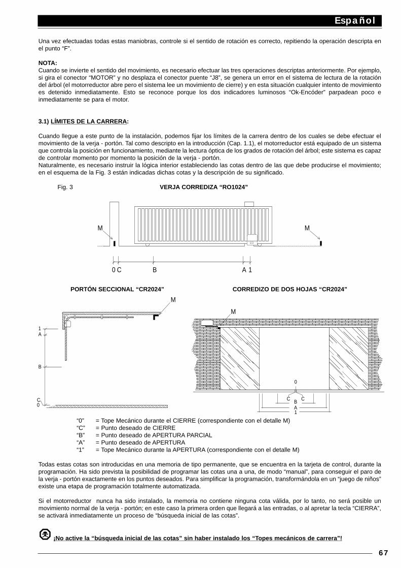
Una vez efectuadas todas estas maniobras, controle si el sentido de rotación es correcto, repitiendo la operación descripta enel punto “F”.
NOTA:Cuando se invierte el sentido del movimiento, es necesario efectuar las tres operaciones descriptas anteriormente. Por ejemplo,si gira el conector “MOTOR” y no desplaza el conector puente “J8”, se genera un error en el sistema de lectura de la rotacióndel árbol (el motorreductor abre pero el sistema lee un movimiento de cierre) y en esta situación cualquier intento de movimientoes detenido inmediatamente. Esto se reconoce porque los dos indicadores luminosos “Ok-Encóder” parpadean poco einmediatamente se para el motor.
3.1) LÍMITES DE LA CARRERA:
Cuando llegue a este punto de la instalación, podemos fijar los límites de la carrera dentro de los cuales se debe efectuar elmovimiento de la verja - portón. Tal como descripto en la introducción (Cap. 1.1), el motorreductor está equipado de un sistemaque controla la posición en funcionamiento, mediante la lectura óptica de los grados de rotación del árbol; este sistema es capazde controlar momento por momento la posición de la verja - portón.Naturalmente, es necesario instruir la lógica interior estableciendo las cotas dentro de las que debe producirse el movimiento;en el esquema de la Fig. 3 están indicadas dichas cotas y la descripción de su significado.
Fig. 3 VERJA CORREDIZA “RO1024”
PORTÓN SECCIONAL “CR2024” CORREDIZO DE DOS HOJAS “CR2024”
“0” = Tope Mecánico durante el CIERRE (correspondiente con el detalle M)“C” = Punto deseado de CIERRE“B” = Punto deseado de APERTURA PARCIAL“A” = Punto deseado de APERTURA“1” = Tope Mecánico durante la APERTURA (correspondiente con el detalle M)
Todas estas cotas son introducidas en una memoria de tipo permanente, que se encuentra en la tarjeta de control, durante laprogramación. Ha sido prevista la posibilidad de programar las cotas una a una, de modo “manual”, para conseguir el paro dela verja - portón exactamente en los puntos deseados. Para simplificar la programación, transformándola en un “juego de niños”existe una etapa de programación totalmente automatizada.
Si el motorreductor nunca ha sido instalado, la memoria no contiene ninguna cota válida, por lo tanto, no será posible unmovimiento normal de la verja - portón; en este caso la primera orden que llegará a las entradas, o al apretar la tecla “CIERRA”,se activará inmediatamente un proceso de “búsqueda inicial de las cotas”.
¡No active la “búsqueda inicial de las cotas” sin haber instalado los “T opes mecánicos de carrera”!
Español
67
MM
0 C B A 1
M
M
1A
B
C 0
C C
0
BA1
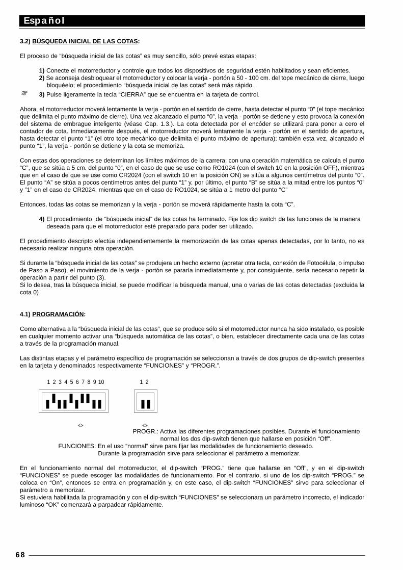
3.2) BÚSQUEDA INICIAL DE LAS COTAS:
El proceso de “búsqueda inicial de las cotas” es muy sencillo, sólo prevé estas etapas:
1) Conecte el motorreductor y controle que todos los dispositivos de seguridad estén habilitados y sean eficientes.2) Se aconseja desbloquear el motorreductor y colocar la verja - portón a 50 - 100 cm. del tope mecánico de cierre, luego
bloquéelo; el procedimiento “búsqueda inicial de las cotas” será más rápido.
3) Pulse ligeramente la tecla “CIERRA” que se encuentra en la tarjeta de control.
Ahora, el motorreductor moverá lentamente la verja - portón en el sentido de cierre, hasta detectar el punto “0” (el tope mecánicoque delimita el punto máximo de cierre). Una vez alcanzado el punto “0”, la verja - portón se detiene y esto provoca la conexióndel sistema de embrague inteligente (véase Cap. 1.3.). La cota detectada por el encóder se utilizará para poner a cero elcontador de cota. Inmediatamente después, el motorreductor moverá lentamente la verja - portón en el sentido de apertura,hasta detectar el punto “1” (el otro tope mecánico que delimita el punto máximo de apertura); también esta vez, alcanzado elpunto “1”, la verja - portón se detiene y la cota se memoriza.
Con estas dos operaciones se determinan los límites máximos de la carrera; con una operación matemática se calcula el punto“C”, que se sitúa a 5 cm. del punto “0”, en el caso de que se use como RO1024 (con el switch 10 en la posición OFF), mientrasque en el caso de que se use como CR2024 (con el switch 10 en la posición ON) se sitúa a algunos centímetros del punto “0”.El punto “A” se sitúa a pocos centímetros antes del punto “1” y, por último, el punto “B” se sitúa a la mitad entre los puntos “0”y ”1” en el caso de CR2024, mientras que en el caso de RO1024, se sitúa a 1 metro del punto “C”
Entonces, todas las cotas se memorizan y la verja - portón se moverá rápidamente hasta la cota “C”.
4) El procedimiento de “búsqueda inicial” de las cotas ha terminado. Fije los dip switch de las funciones de la manera deseada para que el motorreductor esté preparado para poder ser utilizado.
El procedimiento descripto efectúa independientemente la memorización de las cotas apenas detectadas, por lo tanto, no esnecesario realizar ninguna otra operación.
Si durante la “búsqueda inicial de las cotas” se produjera un hecho externo (apretar otra tecla, conexión de Fotocélula, o impulsode Paso a Paso), el movimiento de la verja - portón se pararía inmediatamente y, por consiguiente, sería necesario repetir laoperación a partir del punto (3).Si lo desea, tras la búsqueda inicial, se puede modificar la búsqueda manual, una o varias de las cotas detectadas (excluida lacota 0)
4.1) PROGRAMACIÓN:
Como alternativa a la “búsqueda inicial de las cotas”, que se produce sólo si el motorreductor nunca ha sido instalado, es posibleen cualquier momento activar una “búsqueda automática de las cotas”, o bien, establecer directamente cada una de las cotasa través de la programación manual.
Las distintas etapas y el parámetro específico de programación se seleccionan a través de dos grupos de dip-switch presentesen la tarjeta y denominados respectivamente “FUNCIONES” y “PROGR.”.
a aPROGR.: Activa las diferentes programaciones posibles. Durante el funcionamiento
normal los dos dip-switch tienen que hallarse en posición “Off”.FUNCIONES: En el uso “normal” sirve para fijar las modalidades de funcionamiento deseado.
Durante la programación sirve para seleccionar el parámetro a memorizar.
En el funcionamiento normal del motorreductor, el dip-switch “PROG.” tiene que hallarse en “Off”, y en el dip-switch“FUNCIONES” se puede escoger las modalidades de funcionamiento. Por el contrario, si uno de los dip-switch “PROG.” secoloca en “On”, entonces se entra en programación y, en este caso, el dip-switch “FUNCIONES” sirve para seleccionar elparámetro a memorizar.Si estuviera habilitada la programación y con el dip-switch “FUNCIONES” se seleccionara un parámetro incorrecto, el indicadorluminoso “OK” comenzará a parpadear rápidamente.
Español
68
1 2 3 4 5 6 7 8 9 10 1 2
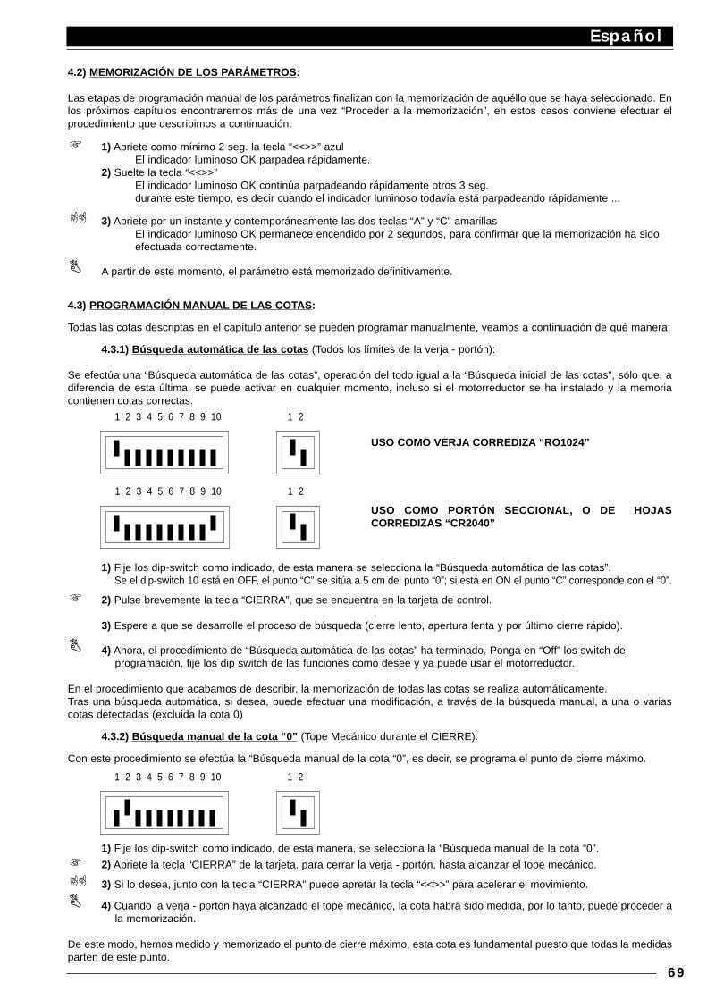
4.2) MEMORIZACIÓN DE LOS PARÁMETROS:
Las etapas de programación manual de los parámetros finalizan con la memorización de aquéllo que se haya seleccionado. Enlos próximos capítulos encontraremos más de una vez “Proceder a la memorización”, en estos casos conviene efectuar elprocedimiento que describimos a continuación:
1) Apriete como mínimo 2 seg. la tecla “<<>>” azulEl indicador luminoso OK parpadea rápidamente.
2) Suelte la tecla “<<>>”El indicador luminoso OK continúa parpadeando rápidamente otros 3 seg.durante este tiempo, es decir cuando el indicador luminoso todavía está parpadeando rápidamente ...
3) Apriete por un instante y contemporáneamente las dos teclas “A” y “C” amarillasEl indicador luminoso OK permanece encendido por 2 segundos, para confirmar que la memorización ha sido efectuada correctamente.
A partir de este momento, el parámetro está memorizado definitivamente.
4.3) PROGRAMACIÓN MANUAL DE LAS COTAS:
Todas las cotas descriptas en el capítulo anterior se pueden programar manualmente, veamos a continuación de qué manera:
4.3.1) Búsqueda automática de las cotas (Todos los límites de la verja - portón):
Se efectúa una “Búsqueda automática de las cotas”, operación del todo igual a la “Búsqueda inicial de las cotas”, sólo que, adiferencia de esta última, se puede activar en cualquier momento, incluso si el motorreductor se ha instalado y la memoriacontienen cotas correctas.
1) Fije los dip-switch como indicado, de esta manera se selecciona la “Búsqueda automática de las cotas”.Se el dip-switch 10 está en OFF, el punto “C” se sitúa a 5 cm del punto “0”; si está en ON el punto “C” corresponde con el “0”.
2) Pulse brevemente la tecla “CIERRA”, que se encuentra en la tarjeta de control.
3) Espere a que se desarrolle el proceso de búsqueda (cierre lento, apertura lenta y por último cierre rápido).
4) Ahora, el procedimiento de “Búsqueda automática de las cotas” ha terminado. Ponga en “Off” los switch de programación, fije los dip switch de las funciones como desee y ya puede usar el motorreductor.
En el procedimiento que acabamos de describir, la memorización de todas las cotas se realiza automáticamente.Tras una búsqueda automática, si desea, puede efectuar una modificación, a través de la búsqueda manual, a una o variascotas detectadas (excluida la cota 0)
4.3.2) Búsqueda manual de la cota “0” (Tope Mecánico durante el CIERRE):
Con este procedimiento se efectúa la “Búsqueda manual de la cota “0”, es decir, se programa el punto de cierre máximo.
1) Fije los dip-switch como indicado, de esta manera, se selecciona la “Búsqueda manual de la cota “0”.
2) Apriete la tecla “CIERRA” de la tarjeta, para cerrar la verja - portón, hasta alcanzar el tope mecánico.
3) Si lo desea, junto con la tecla “CIERRA” puede apretar la tecla “<<>>” para acelerar el movimiento.
4) Cuando la verja - portón haya alcanzado el tope mecánico, la cota habrá sido medida, por lo tanto, puede proceder ala memorización.
De este modo, hemos medido y memorizado el punto de cierre máximo, esta cota es fundamental puesto que todas la medidasparten de este punto.
Español
69
1 2 3 4 5 6 7 8 9 10 1 2
1 2 3 4 5 6 7 8 9 10 1 2
USO COMO VERJA CORREDIZA “RO1024”
USO COMO PORTÓN SECCIONAL, O DE HOJASCORREDIZAS “CR2040”
1 2 3 4 5 6 7 8 9 10 1 2
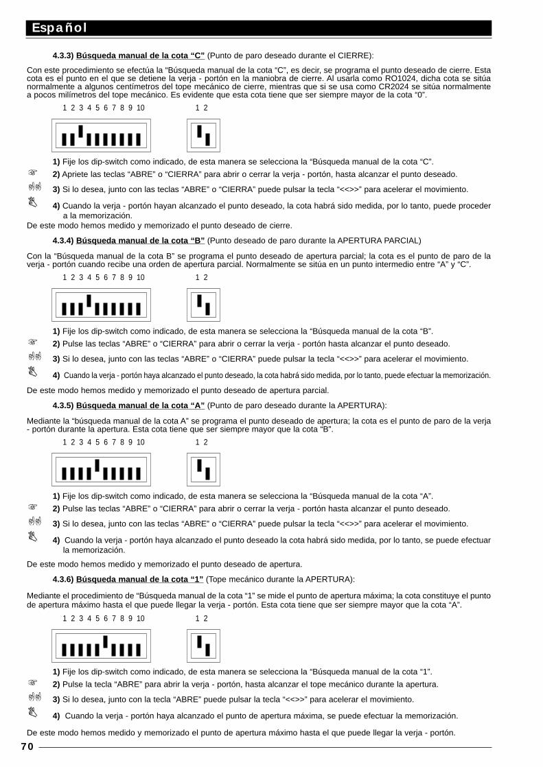
4.3.3) Búsqueda manual de la cota “C” (Punto de paro deseado durante el CIERRE):
Con este procedimiento se efectúa la “Búsqueda manual de la cota “C”, es decir, se programa el punto deseado de cierre. Estacota es el punto en el que se detiene la verja - portón en la maniobra de cierre. Al usarla como RO1024, dicha cota se sitúanormalmente a algunos centímetros del tope mecánico de cierre, mientras que si se usa como CR2024 se sitúa normalmentea pocos milímetros del tope mecánico. Es evidente que esta cota tiene que ser siempre mayor de la cota “0”.
1) Fije los dip-switch como indicado, de esta manera se selecciona la “Búsqueda manual de la cota “C”.
2) Apriete las teclas “ABRE” o “CIERRA” para abrir o cerrar la verja - portón, hasta alcanzar el punto deseado.
3) Si lo desea, junto con las teclas “ABRE” o “CIERRA” puede pulsar la tecla “<<>>” para acelerar el movimiento.
4) Cuando la verja - portón hayan alcanzado el punto deseado, la cota habrá sido medida, por lo tanto, puede procedera la memorización.
De este modo hemos medido y memorizado el punto deseado de cierre.
4.3.4) Búsqueda manual de la cota “B” (Punto deseado de paro durante la APERTURA PARCIAL)
Con la “Búsqueda manual de la cota B” se programa el punto deseado de apertura parcial; la cota es el punto de paro de laverja - portón cuando recibe una orden de apertura parcial. Normalmente se sitúa en un punto intermedio entre “A” y “C”.
1) Fije los dip-switch como indicado, de esta manera se selecciona la “Búsqueda manual de la cota “B”.
2) Pulse las teclas “ABRE” o “CIERRA” para abrir o cerrar la verja - portón hasta alcanzar el punto deseado.
3) Si lo desea, junto con las teclas “ABRE” o “CIERRA” puede pulsar la tecla “<<>>” para acelerar el movimiento.
4) Cuando la verja - portón haya alcanzado el punto deseado, la cota habrá sido medida, por lo tanto, puede efectuar la memorización.
De este modo hemos medido y memorizado el punto deseado de apertura parcial.
4.3.5) Búsqueda manual de la cota “A” (Punto de paro deseado durante la APERTURA):
Mediante la “búsqueda manual de la cota A” se programa el punto deseado de apertura; la cota es el punto de paro de la verja- portón durante la apertura. Esta cota tiene que ser siempre mayor que la cota “B”.
1) Fije los dip-switch como indicado, de esta manera se selecciona la “Búsqueda manual de la cota “A”.
2) Pulse las teclas “ABRE” o “CIERRA” para abrir o cerrar la verja - portón hasta alcanzar el punto deseado.
3) Si lo desea, junto con las teclas “ABRE” o “CIERRA” puede pulsar la tecla “<<>>” para acelerar el movimiento.
4) Cuando la verja - portón haya alcanzado el punto deseado la cota habrá sido medida, por lo tanto, se puede efectuarla memorización.
De este modo hemos medido y memorizado el punto deseado de apertura.
4.3.6) Búsqueda manual de la cota “1” (Tope mecánico durante la APERTURA):
Mediante el procedimiento de “Búsqueda manual de la cota “1” se mide el punto de apertura máxima; la cota constituye el puntode apertura máximo hasta el que puede llegar la verja - portón. Esta cota tiene que ser siempre mayor que la cota “A”.
1) Fije los dip-switch como indicado, de esta manera se selecciona la “Búsqueda manual de la cota “1”.
2) Pulse la tecla “ABRE” para abrir la verja - portón, hasta alcanzar el tope mecánico durante la apertura.
3) Si lo desea, junto con la tecla “ABRE” puede pulsar la tecla “<<>>” para acelerar el movimiento.
4) Cuando la verja - portón haya alcanzado el punto de apertura máxima, se puede efectuar la memorización.
De este modo hemos medido y memorizado el punto de apertura máximo hasta el que puede llegar la verja - portón.
Español
70
1 2 3 4 5 6 7 8 9 10 1 2
1 2 3 4 5 6 7 8 9 10 1 2
1 2 3 4 5 6 7 8 9 10 1 2
1 2 3 4 5 6 7 8 9 10 1 2

4.4) PROGRAMACIÓN DEL TIEMPO DE PAUSA:
Cuando se selecciona la función de cierre automático, mediante el dip-switch correspondiente (véase Cap. 5.1), tras unamaniobra de apertura se activa un temporizador que controla el llamado “Tiempo de Pausa”. Cuando termina dicho tiempo, seactiva automáticamente una maniobra de cierre. Este tiempo, si nunca ha sido programado, se establece en 30 seg. pero, pormedio una operación específica, se puede seleccionar un valor cualquiera de tiempo, entre 1 y 1023 segundos (aprox. 17minutos).
Para establecer el “Tiempo Pausa”, efectúe las siguientes operaciones:
1) Fije los dip-switch de 2 vías como indicado, de este modo se selecciona la “Programación del tiempo de Pausa”.
2) Seleccione el tiempo deseado con el dip-switch de 10 vías:
Dip 1 On = 1 segundoDip 2 On = 2 segundosDip 3 On = 4 “Dip 4 On = 8 “Dip 5 On = 16 “Dip 6 On = 32 “Dip 7 On = 64 “Dip 8 On = 128 “Dip 9 On = 256 “Dip 10 On = 512 “
Luego, si desea obtener por ej. 25 segundos, será necesario poner en On los dip 5, 4 y 1 (la suma de 16+8+1=25)
3) Una vez seleccionado el tiempo, se puede efectuar la memorización.
Con esta operación se memoriza el “Tiempo de Pausa” para las maniobras en ciclo automático.
4.5) ANULACIÓN DE LA MEMORIA:
Todos los parámetros programables se memorizan en una memoria de tipo permanente presente en la tarjeta, pero a vecespuede ser necesario anular en bloque todo aquéllo que ha sido memorizado. Para anular todo el contenido de la memoria, esnecesario efectuar las siguientes operaciones:
1) Fije los dip-switch como indicado, de este modo se selecciona la función de “Anulación de la Memoria”.
2) Luego, puede efectuar la memorización que, en este caso, sirve para confirmar la anulación.
Con estas operaciones se anulan completamente los parámetros contenidos en la memoria. ATENCIÓN: con la memoria puestaa cero es como si el motorreductor nunca se hubiera instalado, por lo tanto, no será posible el movimiento normal de la verja -portón. En este caso, el primer mando que llegará a las entradas al apretar la tecla “CIERRA”, activará inmediatamente unprocedimiento de “Búsqueda inicial de las cotas”.
Español
71
1 2 3 4 5 6 7 8 9 10 1 2
1 2 3 4 5 6 7 8 9 10 1 2
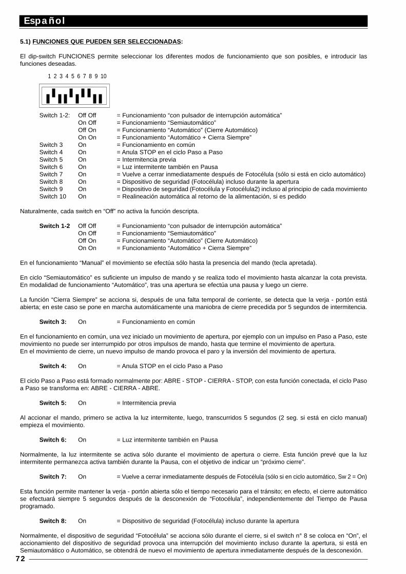
5.1) FUNCIONES QUE PUEDEN SER SELECCIONADAS :
El dip-switch FUNCIONES permite seleccionar los diferentes modos de funcionamiento que son posibles, e introducir lasfunciones deseadas.
Switch 1-2: Off Off = Funcionamiento “con pulsador de interrupción automática”On Off = Funcionamiento “Semiautomático”Off On = Funcionamiento “Automático” (Cierre Automático)On On = Funcionamiento “Automático + Cierra Siempre”
Switch 3 On = Funcionamiento en comúnSwitch 4 On = Anula STOP en el ciclo Paso a PasoSwitch 5 On = Intermitencia previaSwitch 6 On = Luz intermitente también en PausaSwitch 7 On = Vuelve a cerrar inmediatamente después de Fotocélula (sólo si está en ciclo automático)Switch 8 On = Dispositivo de seguridad (Fotocélula) incluso durante la aperturaSwitch 9 On = Dispositivo de seguridad (Fotocélula y Fotocélula2) incluso al principio de cada movimientoSwitch 10 On = Realineación automática al retorno de la alimentación, si es pedido
Naturalmente, cada switch en “Off” no activa la función descripta.
Switch 1-2 Off Off = Funcionamiento “con pulsador de interrupción automática”On Off = Funcionamiento “Semiautomático”Off On = Funcionamiento “Automático” (Cierre Automático)On On = Funcionamiento “Automático + Cierra Siempre”
En el funcionamiento “Manual” el movimiento se efectúa sólo hasta la presencia del mando (tecla apretada).
En ciclo “Semiautomático” es suficiente un impulso de mando y se realiza todo el movimiento hasta alcanzar la cota prevista.En modalidad de funcionamiento “Automático”, tras una apertura se efectúa una pausa y luego un cierre.
La función “Cierra Siempre” se acciona si, después de una falta temporal de corriente, se detecta que la verja - portón estáabierta; en este caso se pone en marcha automáticamente una maniobra de cierre precedida por 5 segundos de intermitencia.
Switch 3: On = Funcionamiento en común
En el funcionamiento en común, una vez iniciado un movimiento de apertura, por ejemplo con un impulso en Paso a Paso, estemovimiento no puede ser interrumpido por otros impulsos de mando, hasta que termine el movimiento de apertura. En el movimiento de cierre, un nuevo impulso de mando provoca el paro y la inversión del movimiento de apertura.
Switch 4: On = Anula STOP en el ciclo Paso a Paso
El ciclo Paso a Paso está formado normalmente por: ABRE - STOP - CIERRA - STOP, con esta función conectada, el ciclo Pasoa Paso se transforma en: ABRE - CIERRA - ABRE.
Switch 5: On = Intermitencia previa
Al accionar el mando, primero se activa la luz intermitente, luego, transcurridos 5 segundos (2 seg. si está en ciclo manual)empieza el movimiento.
Switch 6: On = Luz intermitente también en Pausa
Normalmente, la luz intermitente se activa sólo durante el movimiento de apertura o cierre. Esta función prevé que la luzintermitente permanezca activa también durante la Pausa, con el objetivo de indicar un “próximo cierre”.
Switch 7: On = Vuelve a cerrar inmediatamente después de Fotocélula (sólo si en ciclo automático, Sw 2 = On)
Esta función permite mantener la verja - portón abierta sólo el tiempo necesario para el tránsito; en efecto, el cierre automáticose efectuará siempre 5 segundos después de la desconexión de “Fotocélula”, independientemente del Tiempo de Pausaprogramado.
Switch 8: On = Dispositivo de seguridad (Fotocélula) incluso durante la apertura
Normalmente, el dispositivo de seguridad “Fotocélula” se acciona sólo durante el cierre, si el switch n° 8 se coloca en “On”, elaccionamiento del dispositivo de seguridad provoca una interrupción del movimiento incluso durante la apertura, si está enSemiautomático o Automático, se obtendrá de nuevo el movimiento de apertura inmediatamente después de la desconexión.
Español
72
1 2 3 4 5 6 7 8 9 10
Switch 9: On = Dispositivo de seguridad (Fotocélula y Fotocélula2) incluso al principio de cada movimiento
Normalmente, el dispositivo de seguridad “Fotocélula” se acciona sólo durante el cierre y “Fotocélula2” se acciona durante laapertura. Si desea aumentar el nivel de seguridad, es posible, antes de empezar el movimiento, comprobar el asenso de losdispositivos de seguridad “Fotocélula” y “Fotocélula2”; luego, inicie el movimiento.
Switch 10: On = Realineación automática en el momento del retorno de la alimentación, si es pedido.
Cuando falta la corriente eléctrica y la verja - portón queda bloqueada, el sistema de lectura de la posición de la verja - portónpierde la cota; por este motivo se ha previsto un procedimiento de “Realineación” que consiste en buscar de nuevo el punto “C”.El procedimiento de realineación se realiza normalmente, tras el retorno de la corriente eléctrica, cuando llega el primer impulsode mando. Con el dip-switch n° 10 en “On”, la realineación se produce ni bien vuelve la corriente y sin tener que esperarimpulsos de mando.
6.1) PRUEBA DE FUNCIONAMIENTO:
Comprobadas las conexiones (Cap. 2.4) y efectuada la programación de los límites de carrera (Cap. 3.2 ó 4.3.1), se puedeprobar el movimiento del accionador. Se aconseja trabajar en modalidad “con pulsador de interrupción automática”, con todaslas funciones desactivadas (todos los switch Off). Ante posibles imprevistos, con la modalidad “con pulsador de interrupciónautomática”, soltando la tecla de mando se obtiene detener inmediatamente el motor. Si se emplea como mando la entrada Pasoa Paso, el primer movimiento (tras el encendido) tendrá que ser de apertura.. En esta etapa es muy cómodo emplear las teclas“AP”, “CH” que se encuentran en la tarjeta. Actuando sobre las entradas de mando, desplace la verja - portón hasta el puntodeseado de apertura “A”, aproximadamente unos 20 cm.; antes del punto de paro tiene que accionarse la etapa de“deceleración” que permite alcanzar el punto previsto a una velocidad reducida de casi un 30%. Luego, realice un movimientode cierre hasta alcanzar el punto deseado de cierre “C”; también en este caso tendrá que accionarse la etapa de deceleración,20 cm. antes que se detenga el movimiento. Pruebe ahora la conexión de los dispositivos de seguridad; FOTOCÉLULA durantela apertura no tiene ningún efecto, durante el cierre detiene el movimiento; FOTOCÉLULA2 durante el cierre no tiene ningúnefecto, durante la apertura detiene el movimiento. Los dispositivos conectados a la entrada STOP actúan tanto durante laapertura como durante el cierre, deteniendo siempre el movimiento.
Las nuevas normativas europeas prEN 12453: seguridad en el uso de las puertas motorizadas – requisitos y clasificaciones, yprEN 12445: seguridad en el uso de las puertas motorizadas – métodos de prueba (no aprobadas aún definitivamente, pero encurso de aprobación durante el año 1998), requieren la adopción de medidas para limitar las fuerzas en el movimiento de laspuertas automáticas, igual a un máximo de 1400N como fuerza de choque; una fuerza residual estática máxima de 150N, queluego debe ser anulada antes de 5 segundos del choque.Esto se obtiene regulando el embrague electrónico inteligente. En la tarjeta se encuentra el trimmer FRIZZ que permiteestablecer el umbral de accionamiento del embrague.
Como descripto en el Cap. 1.3, el sistema de embrague inteligente trabaja con una serie de cálculos para obtener la velocidadmedia del movimiento y, por lo tanto, actuar con mayor precisión.. Para evaluar el efecto de la regulación del trimmer, esconveniente esperar que el movimiento se ponga en marcha y que la verja - portón haya alcanzado la velocidad estándar.También tenga cuidado al hecho de que si el embrague se acciona tres veces consecutivas, el movimiento se parará sin haberrealizado la inversión.
Si selecciona el modo de funcionamiento automático, al final de la maniobra de apertura se efectuará una “Pausa”, al final dela cual se efectúa automáticamente una maniobra de cierre. El tiempo de pausa, si no ha sido programado mediante elprocedimiento correspondiente, es de 30 segundos.
La pausa también se activa durante el movimiento semiautomático, cuando, durante el cierre, el accionamiento de un dispositivode seguridad o del embrague inteligente provoca una inversión durante la apertura.
Sólo ahora, una vez finalizadas todas las regulaciones y sin corriente eléctrica, aconsejamos introducir el radiorreceptor.
6.2) DESCRIPCIÓN DE LAS MODALIDADES DE FUNCIONAMIENT O:
En el funcionamiento de “pulsador de interrupción automática”, la entrada ABRE-RELOJ permite el movimiento hasta el puntodeseado de apertura. La entrada ABRE PAR. permite el movimiento hasta el punto de apertura parcial. La entrada PASO aPASO permite un movimiento alternativo de apertura y cierre. Ni bien cesa el mando de entrada, el movimiento se detiene.Durante la apertura, el movimiento se detiene en el punto previsto, o si falta el asenso de la FOTOCÉLULA2. Por el contrario,durante el cierre el movimiento se detiene también si falta el asenso de la FOTOCÉLULA. Una accionamiento en STOP provocael paro inmediato del movimiento, tanto durante la apertura como durante el cierre. Una vez que el movimiento se hayadetenido, es necesario cesar el mando en entrada antes de poder iniciar un nuevo movimiento.
En el funcionamiento de uno de las modalidades automáticas (semiautomático - automático y cierra siempre) un mando en laentrada ABRE-RELOJ provoca el movimiento de apertura, si el mando se mantiene, una vez alcanzada la apertura, elmovimiento permanece “congelado” en una pausa infinita, sólo cuando cesará el mando, la verja - portón se podrá cerrar. Losimpulsos de mando en la entrada ABRE PAR provocan sólo la apertura hasta el punto de apertura parcial. Un impulso en PASOa P. provoca, alternativamente, una apertura o un cierre. Un segundo impulso en PASO a P., o en la misma entrada que ha
Español
73
empezado el movimiento, provoca un Stop.
Tanto durante la apertura como durante el cierre, un accionamiento en STOP provoca el paro inmediato del movimiento.
Si en una entrada de mando en lugar de un impulso se mantiene una señal continua, se provoca un estado de “prevalencia”·en el que las demás entradas de mando quedan deshabilitadas (útil para conectar un reloj o un selector Noche - Día).
Si se conectara la modalidad de funcionamiento automático, después de una maniobra de apertura, se realiza una pausa y alfinal se efectúa un cierre. Si durante la pausa se produjera un accionamiento de FOTOCÉLULA, el temporizador se restablecerácon un nuevo tiempo; por el contrario, si durante la pausa se acciona STOP, la función de cierre se anula y se pasa a un estadode STOP.
Durante la apertura el accionamiento de la FOTOCÉLULA no tiene efecto, mientras que la FOTOCÉLULA2 provoca la inversióndel movimiento. Durante el cierre el accionamiento de la FOTOCÉLULA provoca una inversión de movimiento, luego una nuevapausa y por último un cierre. Si al inicio del movimiento de apertura, la entrada FOTOCÉLULA no da el asenso, la solicitud deapertura queda anulada.
7.1) TARJETA “CARGA” para alimentación también desde batería
El motorreductor tiene un transformador de potencia adecuada para soportar la demanda de energía del motor y de la tarjetaelectrónica, permitiendo que todo se pueda alimentar directamente desde la red.
Si desea que el sistema siga funcionando incluso cuando falta la energía eléctrica en la red, añada una batería idónea con latarjeta carga batería correspondiente.
La batería, vistas las relevantes dimensiones, se tiene que instalar fuera del motorreductor y conectar a los dos bornes de latarjeta carga batería, mientras que esta última se conecta en el conector colocado en la central.
8) MANTENIMIENTO:
Periódicamente, dos veces al año como mínimo, controle la perfecta eficiencia y regulación del dispositivo de control de la fuerzamáxima del motor y, si fuera necesario, actúe sobre el trimmer de regulación.Controle que los dispositivos de protección (fotocélulas, bordes neumáticos, etc.) sean eficientes y que la luz intermitentefuncione correctamente.
CARACTERÍSTICAS TÉCNICAS DE LA CENTRAL:
Alimentación desde red : 230 Vca ±10% , 50 - 60 HzAlimentación desde batería : 21 ÷ 28 Vcc (capacidad > 6Ah)Corriente Máx accesorios 24 Vcc : 200 mAPotencia máxima luz intermitente : 25 W ( 24 Vcc)Potencia máxima del indicador luminoso VA : 2 W ( 24 Vcc)Tiempo de pausa : desde 1 segundo a 1023 segundosResolución Encóder : 4,73 grados (76 impulsos/revoluc.)Temperatura de funcionamiento : -20 ÷ 70 °C
Español
74

Español
75

cart
a ric
icla
ta 1
00%
recy
cled
pap
er 1
00%
papi
er r
ecyc
le 1
00%
100%
Altp
apie
r10
0% p
apel
rec
icla
do
Via Pezza Alta n° 13 - Z.I. di Rustigne31046 ODERZO - TV - ITALYTel. 0422/853838 - Fax 0422/853585http://www.niceforyou.com - email: [email protected]
IST
RC
4858


![Etude de concert pour Piano [Op.59]€¦ · pauSa. SYDNEY dim: e SMITH, Presto agitato. fpp SYDNEY Etta. & —t. la > SYDNEY de > rita rd.' (A.p. 4042.) tempo SYDNEY SMITH, ma POCO](https://img.pdfslide.fr/doc/110x75/5f07567e7e708231d41c7cc2/etude-de-concert-pour-piano-op59-pausa-sydney-dim-e-smith-presto-agitato.jpg)